WO2023181346A1 - 検査支援装置、生産管理システム、および検査支援方法 - Google Patents
検査支援装置、生産管理システム、および検査支援方法 Download PDFInfo
- Publication number
- WO2023181346A1 WO2023181346A1 PCT/JP2022/014381 JP2022014381W WO2023181346A1 WO 2023181346 A1 WO2023181346 A1 WO 2023181346A1 JP 2022014381 W JP2022014381 W JP 2022014381W WO 2023181346 A1 WO2023181346 A1 WO 2023181346A1
- Authority
- WO
- WIPO (PCT)
- Prior art keywords
- component
- inspection
- mounting
- image data
- board
- Prior art date
Links
- 238000007689 inspection Methods 0.000 title claims abstract description 116
- 238000000034 method Methods 0.000 title claims description 43
- 238000004519 manufacturing process Methods 0.000 title claims description 31
- 230000008569 process Effects 0.000 claims description 32
- 238000003384 imaging method Methods 0.000 claims description 25
- 238000012546 transfer Methods 0.000 claims description 24
- 238000012360 testing method Methods 0.000 claims description 7
- 239000000463 material Substances 0.000 claims description 2
- 239000000758 substrate Substances 0.000 abstract description 23
- 235000012431 wafers Nutrition 0.000 description 38
- 238000012545 processing Methods 0.000 description 9
- 238000011179 visual inspection Methods 0.000 description 6
- 239000000853 adhesive Substances 0.000 description 3
- 230000001070 adhesive effect Effects 0.000 description 3
- 238000010586 diagram Methods 0.000 description 3
- 230000006870 function Effects 0.000 description 3
- 230000007246 mechanism Effects 0.000 description 3
- 238000011144 upstream manufacturing Methods 0.000 description 3
- 238000009434 installation Methods 0.000 description 2
- 239000011159 matrix material Substances 0.000 description 2
- 238000005259 measurement Methods 0.000 description 2
- 229910000679 solder Inorganic materials 0.000 description 2
- NIXOWILDQLNWCW-UHFFFAOYSA-N acrylic acid group Chemical group C(C=C)(=O)O NIXOWILDQLNWCW-UHFFFAOYSA-N 0.000 description 1
- 239000011248 coating agent Substances 0.000 description 1
- 238000000576 coating method Methods 0.000 description 1
- 230000007547 defect Effects 0.000 description 1
- 230000002950 deficient Effects 0.000 description 1
- 239000012636 effector Substances 0.000 description 1
- 230000000694 effects Effects 0.000 description 1
- 238000011990 functional testing Methods 0.000 description 1
- 239000011521 glass Substances 0.000 description 1
- 238000012423 maintenance Methods 0.000 description 1
- 239000000155 melt Substances 0.000 description 1
- 230000015654 memory Effects 0.000 description 1
- 238000012986 modification Methods 0.000 description 1
- 230000004048 modification Effects 0.000 description 1
- 238000005476 soldering Methods 0.000 description 1
- 230000032258 transport Effects 0.000 description 1
- 230000007723 transport mechanism Effects 0.000 description 1
Images


Classifications
-
- H—ELECTRICITY
- H01—ELECTRIC ELEMENTS
- H01L—SEMICONDUCTOR DEVICES NOT COVERED BY CLASS H10
- H01L21/00—Processes or apparatus adapted for the manufacture or treatment of semiconductor or solid state devices or of parts thereof
- H01L21/02—Manufacture or treatment of semiconductor devices or of parts thereof
- H01L21/04—Manufacture or treatment of semiconductor devices or of parts thereof the devices having at least one potential-jump barrier or surface barrier, e.g. PN junction, depletion layer or carrier concentration layer
- H01L21/50—Assembly of semiconductor devices using processes or apparatus not provided for in a single one of the subgroups H01L21/06 - H01L21/326, e.g. sealing of a cap to a base of a container
- H01L21/60—Attaching or detaching leads or other conductive members, to be used for carrying current to or from the device in operation
-
- H—ELECTRICITY
- H05—ELECTRIC TECHNIQUES NOT OTHERWISE PROVIDED FOR
- H05K—PRINTED CIRCUITS; CASINGS OR CONSTRUCTIONAL DETAILS OF ELECTRIC APPARATUS; MANUFACTURE OF ASSEMBLAGES OF ELECTRICAL COMPONENTS
- H05K13/00—Apparatus or processes specially adapted for manufacturing or adjusting assemblages of electric components
- H05K13/02—Feeding of components
Definitions
- the present invention relates to an inspection support device, a production management system, and an inspection support method.
- a visual inspection is performed to check whether the components mounted on the circuit board are in the specified mounting position.
- the error from the mounting position of the component is measured based on the positional relationship of the external shape of the component with respect to the reference position of the board (see Patent Document 1).
- some of the above-mentioned parts are mounted so that the characteristic parts such as bumps (electrodes) formed on the back side of the part are in a predetermined positional relationship with respect to the reference position of the board.
- Parts that are mounted based on such features on the back surface have individual differences in the positional relationship between the features on the back surface and the external shape visually recognized from the front surface. Therefore, in the appearance inspection that depends on the external shape, there is a concern that the inspection accuracy may be reduced by the above-mentioned individual differences.
- the purpose of this specification is to provide an inspection support device, a production management system equipped with the inspection support device, and an inspection support method that can improve the accuracy of visual inspection.
- This specification includes: an image acquisition unit that acquires image data by capturing images of the front and back surfaces of the component in a supply process in which a component supply unit supplies the component to a component mounting machine so that the component can be picked up; a component analysis unit that determines the positional relationship of a characteristic part on the back side of the component with respect to the appearance of the front side of the component and stores it as characteristic part information; Disclosed is an inspection support device comprising: a storage unit that stores mounting information indicating a mounting position of a component in association with the characteristic part information so as to be readable by an inspection device that performs an external appearance inspection of the board on which the component is mounted. .
- This specification discloses a production management system including the above-described inspection support device, the component supply unit, the component mounting machine, and the inspection device.
- This specification includes an image acquisition step of acquiring image data by imaging the front and back surfaces of the component in a supply process in which the component supply unit supplies the component to the component mounting machine so that the component can be collected; a component analysis step of determining the positional relationship of a characteristic part on the back side of the component with respect to the appearance of the front side of the component and storing it as characteristic part information;
- an inspection support device comprising: a storing step of associating mounting information indicating a mounting position of a component with the characteristic portion information so as to be readable by an inspection device that performs an external appearance inspection of the board on which the component is mounted. .
- FIG. 2 is a plan view schematically showing a component mounting machine, a component supply unit, and a wafer supply device.
- FIG. 3 is a plan view showing a part of the component supply unit.
- FIG. 4 is a side view as seen in the IV direction in FIG. 3.
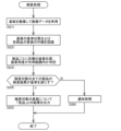
- FIG. It is a functional block diagram of a production line. It is a flowchart which shows test support processing. It is a figure showing an example of image data.
- FIG. 7 is a diagram showing characteristic part information and mounting information based on image data. It is a flowchart which shows inspection processing by an inspection device.
- the production management system 1 and the inspection support device 30 are applied, for example, to a production line Ln including an inspection device 50, as shown in FIG.
- the production line Ln is configured by arranging and installing a plurality of board-facing work machines that perform predetermined board-facing work.
- the production line Ln is configured by installing a plurality of substrate-facing working machines in the direction of conveyance of the substrate 71.
- Each of the plurality of board-oriented working machines is communicably connected to the host computer 2.
- the host computer 2 centrally controls the plurality of production lines Ln.
- the production line Ln includes a printing machine as a plurality of board-facing working machines, a plurality of component mounting machines 10, a reflow oven, and an inspection device 50.
- the printing machine prints paste-like solder on the loaded board 71 at the mounting position of the component.
- Each of the plurality of component mounting machines 10 mounts a component onto the board 71 transported from the upstream side of the production line Ln. The configuration of the component mounting machine 10 will be described later.
- the reflow oven heats the substrate 71 transported from the upstream side of the production line Ln, melts the solder on the substrate 71, and performs soldering.
- the inspection device 50 performs an external appearance inspection of the board products produced by the production line Ln. Details of the inspection device 50 will be described later.
- a plurality of production lines Ln may be configured in the substrate product factory.
- the configuration of each of the plurality of production lines Ln may be appropriately added or changed depending on, for example, the type of board product to be produced.
- the plurality of production lines Ln include a buffer device that temporarily holds the substrate 71 being transported, a substrate supply device, a substrate reversing device, various inspection devices, a shield mounting device, an adhesive coating device, and an ultraviolet irradiation device.
- Board working equipment such as an inspection device that performs a functional test of devices and board products may be installed as appropriate.
- the component mounting machine 10 includes a board transfer device 11, as shown in FIG.
- the substrate transfer device 11 sequentially transfers the substrates 71 in the transfer direction and positions the substrates 71 at a predetermined position within the machine.
- the component mounting machine 10 includes a component supply device 12 .
- the component supply device 12 supplies components to be mounted on the board 71.
- the component supply device 12 is equipped with feeders 122 in a plurality of slots 121, respectively.
- the feeder 122 is, for example, a tape feeder that feeds and moves a carrier tape containing a large number of parts so as to be able to collect the parts.
- various component supply units depending on the mounting process may be used as a device for supplying components in the mounting process.
- a tray component supply device that supplies relatively large components aligned on a tray or a wafer supply device that supplies wafers divided into a plurality of dies can be used as appropriate.
- the component supply unit has a configuration that functions as a part of the component supply device 12 and a configuration that can operate independently as an external device of the component supply device 12.
- the component supply unit 20 is an external device of the component supply device 12, and is arranged in line with the component mounting machine 10 in the conveyance direction of the board 71.
- the component supply unit 20 accesses the inside of the component mounting machine 10 from the side (in the present embodiment, the upstream side in the conveying direction of the board 71), and supplies predetermined components so that they can be collected.
- the component supply unit 20 is interposed between the wafer supply device 40 that supplies the wafer 80 and the component mounting machine 10, and collects a plurality of dies obtained from the wafer supply device 40 and supplies them to the component mounting machine 10. supply Details of the parts supply unit 20 will be described later.
- the component mounting machine 10 includes a component transfer device 13.
- the component transfer device 13 transfers the components supplied by the component supply device 12 to a predetermined mounting position on the board 71.
- the component transfer device 13 includes a head drive device 131, a moving table 132, and a mounting head 133.
- the head drive device 131 moves the moving table 132 in the horizontal direction (X direction and Y direction) using a linear motion mechanism.
- the mounting head 133 is removably fixed to the movable table 132 by a clamp member (not shown), and is provided so as to be movable horizontally within the machine.
- the mounting head 133 supports a plurality of holding members so as to be movable up and down and rotatable around the rotation axis of each of the plurality of holding members.
- the holding member is a suction nozzle 134 that holds the component by suctioning it with supplied negative pressure air.
- a chuck or the like that holds the component by gripping it may be employed.
- the component mounting machine 10 includes a component camera 14 and a board camera 15.
- the component camera 14 and the board camera 15 are digital imaging devices having an imaging element such as a CMOS.
- the component camera 14 and the board camera 15 perform imaging based on the control signal, and send out image data acquired by the imaging.
- the component camera 14 is provided on a base fixed to the installation floor, and is configured to be able to image the component held by the suction nozzle 134 from below.
- the board camera 15 is provided on the movable table 132 so as to be movable in the horizontal direction integrally with the mounting head 133.
- the board camera 15 is configured to be able to image the board 71 from above.
- the component mounting machine 10 includes a control device 16.
- the control device 16 is mainly composed of a CPU, various memories, and control circuits.
- the control device 16 acquires and stores various data such as control data and component information used for controlling the mounting process from the host computer 2.
- the control data indicates the type, mounting position, mounting angle, and mounting order of the component to be mounted on the board 71 in the mounting process.
- the above mounting process includes a collection operation in which the component supplied by the component supply device 12 is collected by a holding member (suction nozzle 134), and a mounting operation in which the component is mounted at a predetermined mounting position on the board 71 at a predetermined mounting angle. It includes a PP cycle (pick and place cycle) that repeatedly performs operations.
- the control device 16 controls the mounting operation by the mounting head 133 so that the component is mounted on the board 71 in a predetermined posture. At this time, the control device 16 controls the mounting operation based on the holding state of the component by the suction nozzle 134 recognized using the component camera 14 and various data. That is, the control device 16 brings the suction nozzle 134 into contact with the suction position on the component designated by the component information to collect the component. The control device 16 also performs image processing on the image data acquired by the component camera 14, and recognizes the holding state of the component.
- the control device 16 lowers the suction nozzle 134 so that the component comes into contact with the substrate 71, and then raises the suction nozzle 134 and supplies positive pressure air to the suction nozzle 134 to attempt to release the component. . Then, the control device 16 moves the suction nozzle 134 away from the component and moves the mounting head 133 to mount the component to the next mounting position.
- the component supply unit 20 is arranged to be interposed between the wafer supply device 40 and the component mounting machine 10.
- the component supply unit 20 is a unit that collectively supplies a plurality of dies 81 (components 90) acquired from the wafer supply device 40 to the component mounting machine 10.
- the wafer supply device 40 stores a wafer pallet 41 in a plurality of storage shelves formed in the housing so that the wafer pallet 41 can be pulled out.
- the wafer pallet 41 holds the periphery of the dicing sheet 42 while applying tension to the dicing sheet 42.
- a wafer 80 that has been divided into a plurality of dies 81 through a dicing process is adhered to the dicing sheet 42 .
- the wafer supply device 40 pulls out a predetermined wafer pallet 41 using a pallet transport mechanism (not shown) and transports it to a supply position.
- the wafer supply device 40 uses a pot (not shown) to push up the wafer pallet 41 along with the dicing sheet 42 from below the wafer pallet 41 positioned at the supply position, and supplies predetermined dies 81 so that they can be collected.
- the wafer supply device 40 moves the pot in the horizontal direction according to the die 81 to be supplied.
- the wafer supply device 40 configured as described above may be arranged so that the supply position of the wafer pallet 41 is inside the component mounting machine 10. Thereby, the component transfer device 13 can directly pick up the die 81 from the wafer supply device 40.
- the pot in the wafer supply device 40, the pot must be moved every time an individual die 81 is supplied, and the wafer pallet 41 must be replaced every time a predetermined number of dies 81 are supplied. Therefore, when performing a mounting process in which a plurality of dies 81 are sequentially mounted, a waiting time may occur during which the wafer supply device 40 waits for the supply operation to end. Therefore, in this embodiment, a configuration is adopted in which a component supply unit 20 is interposed between the component mounting machine 10 and the wafer supply device 40.
- the component supply unit 20 collectively supplies the plurality of dies 81 obtained from the wafer supply device 40 to the component mounting machine 10.
- the component supply unit 20 includes a stage drive device 21, a die transfer device 22, a die camera 23, an upper camera 24, a lower camera 25, and a supply control device 26.
- the stage driving device 21 includes a stage 211 formed with a horizontal mounting surface on which a plurality of dies 81 can be mounted, and a pair of rails 212 that support the stage 211.
- the stage 211 is made of a material that transmits light.
- the stage 211 is made of glass or acrylic, for example.
- the stage 211 is provided with a plurality of reference marks 215 that are visible from above and below.
- the plurality of reference marks 215 are formed, for example, in a circular shape and arranged in a matrix at equal intervals.
- a pair of rails 212 supports the stage 211 so as to be slidable in the conveying direction of the substrate 71 (left-right direction in FIG. 3).
- the stage 211 is moved along a pair of rails 212 by a drive mechanism (not shown).
- the stage 211 moves the die 81 at the receiving position Ps1 where the die 81 is received from the die transfer device 22, at the imaging position Ps2 where images are captured by the upper camera 24 and the lower camera 25, and at the work area Rw which is the inside of the component mounting machine 10. It is positioned at the supply position Ps3 where it supplies.
- the stage 211 may have a function of holding the mounted die 81.
- the above-mentioned holding function is configured by, for example, an adhesive sheet pasted in advance on the mounting surface of the stage 211, or an adhesive applied to the mounting surface.
- an air conduit having an opening may be formed on the mounting surface of the stage 211, and negative pressure air may be supplied to this air conduit to hold the die 81 placed in the opening. .
- the die transfer device 22 transfers the die 81 supplied by the wafer supply device 40 to a predetermined placement position on the stage 211.
- the die transfer device 22 includes a supply head 221 and a suction nozzle 222.
- the supply head 221 is configured to be movable in the horizontal direction (X direction and Y direction) by a drive mechanism (not shown).
- the suction nozzle 222 is supported by the supply head 221 so as to be movable up and down, and holds the die 81 by suctioning it with the supplied negative pressure air.
- the die transfer device 22 described above is exemplified as having a supply head 221 that is an XY robot that moves in the horizontal direction, but it may also be configured as an articulated robot.
- the die transfer device 22 can be configured such that an articulated robot picks up the die 81 using an end effector such as a suction nozzle, and places the die 81 at a predetermined position on the stage 211.
- the die camera 23, the upper camera 24, and the lower camera 25 are digital imaging devices having imaging elements such as CMOS.
- the die camera 23 is disposed between the wafer supply device 40 and the stage 211, and is configured to be able to image the die 81 picked up from the wafer supply device 40 by the die transfer device 22 from below.
- the image data acquired by the die camera 23 is used to recognize the state in which the die 81 is held by the die transfer device 22.
- the upper camera 24 and the lower camera 25 are arranged to face each other in the vertical direction on the movement path of the stage 211.
- the upper camera 24 is configured to be able to image the die 81 placed on the stage 211 from above when the stage 211 is positioned at the imaging position Ps2.
- the lower camera 25 is configured to be able to image the die 81 placed on the stage 211 from below when the stage 211 is positioned at the imaging position Ps2.
- the supply control device 26 cooperates with the wafer supply device 40 to execute a supply process of supplying the dies 81 necessary for the mounting process by the component mounting machine 10. Specifically, the supply control device 26 causes the die transfer device 22 to pick up the die 81 supplied by the wafer supply device 40 . The supply control device 26 recognizes the holding state based on the image data acquired by the die camera 23 . The above-mentioned holding state includes the presence or absence of the die 81 and the position and angle of the die 81 with respect to the reference position of the supply head 221.
- the supply control device 26 places the die 81 at a predetermined position on the stage 211 based on the holding state of the die 81. By repeating such collection operation, state recognition, and mounting operation for the dies 81, a plurality of dies 81 are arranged in a matrix on the stage 211. Subsequently, the supply control device 26 moves the stage 211 from the receiving position Ps1 to the supply position Ps3. In this way, the component supply unit 20 transfers the component 90 (die 81) housed in the wafer supply device 40, which is an external device, to the stage 211, and places the component 90 (die 81) on the stage 211. and supplies it to the component mounting machine 10.
- Configuration of inspection support device 30 5-1 Outline of the mounting process of the component mounting machine 10 and the inspection device 50 During the mounting process, the component mounting machine 10 recognizes the state in which the component is held by the suction nozzle 134 based on the image data acquired by the component camera 14, and Control is performed so that the component is mounted at a predetermined mounting position on the upper part at a predetermined mounting angle. Thereby, the component is mounted such that the electrodes of the component correspond to the land portions formed on the substrate 71, for example.
- the control device 16 controls the position of the electrode based on the external shape of the component.
- the inspection device 50 that performs an appearance inspection determines the reference position of the substrate 71 and the appearance (including the external shape) of the surface of each component based on image data obtained by imaging the substrate 71 on which a large number of components are mounted. ). Then, the inspection device 50 inspects the quality of the board 71 depending on whether the mounting position and mounting angle of each component are within an allowable range.
- the component placement machine 10 recognizes the position of a characteristic part (such as a bump) on the back surface of the component based on the image data acquired by the component camera 14. . Then, the component mounting machine 10 controls the position and angle of the suction nozzle 134 so that the characteristic portion on the back surface of the component has a prescribed positional relationship with respect to a predetermined mounting position on the board 71.
- the production management system 1 and the inspection support device 30 of this embodiment adopt the following configuration that can improve the accuracy of appearance inspection of the above-mentioned parts.
- the inspection support device 30 is incorporated into the component supply unit 20, as shown in FIG.
- the inspection support device 30 includes an image acquisition section 31, a component analysis section 32, and a storage section 33.
- the test support device 30 executes test support processing as an example of a test support method.
- the image acquisition unit 31 images the front surface 91 and the back surface 93 of the component 90 during the supply process in which the component supply unit 20 supplies the component 90 (in this embodiment, the die 81) to the component mounting machine 10 so as to be collectable, and obtains image data.
- D1 is acquired (image acquisition step, see S11 and S12 in FIG. 6, and FIG. 7).
- the above supply process includes a series of operations from when the component supply unit 20 picks up the die 81 from the wafer supply device 40 to when the stage 211 is moved to the supply position Ps3. Further, in the present embodiment, imaging for acquiring the image data D1 is performed by the upper camera 24 and the lower camera 25. Specifically, when the component supply unit 20 moves the stage 211 from the receiving position Ps1 to the supply position Ps3, the image acquisition unit 31 captures images using the upper camera 24 and the lower camera 25 when the component supply unit 20 reaches the imaging position Ps2. conduct.
- the image acquisition unit 31 acquires image data D1 obtained by simultaneously imaging the component 90 placed on the stage 211 from above and below.
- the front surface 91 and back surface 93 of one of the plurality of dies 81 falling within the field of view of the upper camera 24 and the lower camera 25 are combined so as to form a pair.
- the stage 211 may be temporarily stopped at the imaging position Ps2 and images may be taken sequentially from above and below.
- the component analysis unit 32 determines the positional relationship of the characteristic portion 95 (in this embodiment, the bump of the die 81) on the back surface 93 of the component 90 with respect to the appearance of the front surface 91 side of the component 90 based on the image data D1, and obtains characteristic portion information. It is stored as M1 (component analysis step, S13 in FIG. 6). That is, the component analysis unit 32 determines the characteristic portion 95 of the back surface 93 with respect to the appearance when the die 81 is viewed from above.
- the component analysis unit 32 determines the positional relationship between the external appearance on the surface 91 side of the component 90 and the characteristic portion 95 based on the correspondence between the plurality of reference marks 215 included in the image data D1. In other words, the component analysis unit 32 determines the positional relationship of the bumps 95 with respect to the front surface contour 92 by, for example, horizontally reversing the image on the back surface 93 side and overlapping the four reference marks 215 in correspondence with the image on the front surface 91 side. (See Figure 8).
- the component analysis unit 32 determines the positional relationship of the bumps 95 with respect to the front surface outline 92 by, for example, horizontally reversing the image on the back surface 93 side and performing alignment so that the reversed back surface outline 94 matches the front surface outline 92. (See Figure 8).
- the above method (A) is effective when the shape obtained by horizontally inverting the back contour 94 is different from the front contour 92.
- the above method (B) is useful when determining the positional relationship without relying on the reference mark 215 when the reference mark 215 in the image data D1 is unclear or when the reference mark 215 is out of the camera field of view. It is valid.
- the component analysis unit 32 may switch or combine the above methods (A) and (B) depending on the imaging conditions and the situation of the stage 211.
- the component analysis unit 32 performs the above analysis and determines the position of the characteristic portion 95 of the back surface 93 with respect to the appearance of the front surface 91 for each of the plurality of components 90. Then, the component analysis unit 32 calculates the position coordinates (X1, Y1), (X2, Y2), etc. of the plurality of bumps 95 with the center of the component 90 as the origin (X0, Y0), and It is stored as information M1.
- the storage unit 33 stores mounting information M2 indicating the board 71 on which the component mounting machine 10 has collected and mounted the component 90 and the mounting position of the component 90 on the board 71 in association with the feature information M1 (storage step, FIG. S14). That is, the storage unit 33 stores the mounting information M2 including, for example, the identification code (ID) of the board 71 on which the component 90 analyzed by the component analysis unit 32 is mounted, and the mounting position (X11, Y11) on the board 71. It is acquired from the control device 16 of the component mounting machine 10 and stored in association with the feature information M1.
- ID identification code
- the storage unit 33 acquires mounting information M2 from the control device 16 each time a component 90 is collected from the stage 211 and mounted on the board 71, or collectively after a series of PP cycles is completed.
- the storage unit 33 stores the characteristic part information M1 and the mounting information M2 so as to be readable by an inspection device 50 that performs a visual inspection in a process subsequent to the component mounting machine 10 of the production line Ln.
- the storage unit 33 stores characteristic part information M1 and mounting information M2 as the component supply unit 20 performs a supply operation and the component mounting machine 10 performs a mounting process.
- the inspection device 50 performs an appearance inspection using image data acquired by imaging the board 71 from above, when the component 90 to be inspected is mounted on the board 71 with reference to the characteristic portion 95 of the back surface 93. In this step, a quality determination is made based on the feature information M1 and mounting information M2 corresponding to the component 90.
- the inspection device 50 includes a notification section 51 that notifies the outside of the inspection results.
- the device further includes a section 51 (see FIG. 5).
- the notification unit 51 may notify the component mounting machine 10 of an instruction to execute corresponding processing based on the inspection result.
- the notification unit 51 may notify the worker of the test results.
- Inspection processing by the inspection device 50 in the production management system 1 including the inspection support device 30 will be described with reference to FIG. 9 .
- the inspection device 50 acquires the feature information M1 and the mounting information M2 from the inspection support device 30 when executing the inspection process. Furthermore, when the inspection device 50 carries the substrate 71 to be inspected into the machine, it reads the identification code attached to the substrate 71 and acquires the identification code (ID) of the substrate 71 .
- ID identification code
- the inspection device 50 first images the substrate 71 from above to obtain image data (S21). Next, the inspection device 50 recognizes the reference position of the board 71 and the appearance of the surface 91 of each component 90 based on the acquired image data (S22). Subsequently, the inspection device 50 determines whether the mounting position and mounting angle of each of the plurality of components 90 set as the inspection target are within an allowable range with respect to the target mounting position and mounting angle (S23 ). At this time, the inspection device 50 may measure the positional error and the angular error as necessary.
- the inspection device 50 makes a determination based on the appearance of the component 90 mounted on the board 71 based on the appearance of the surface 91 recognized in the appearance recognition process (S22). On the other hand, with respect to the component 90 mounted on the board 71 based on the characteristic portion 95 of the back surface 93, the inspection device 50 first determines the mounting position of the component 90 on the board 71, and stores the mounting information M2 corresponding to this mounting position. The feature information M1 associated with the mounting information M2 is obtained.
- the inspection device 50 acquires the actual position of the characteristic portion 95 on the back surface 93 based on the appearance recognized in the appearance recognition process (S22) and the characteristic portion information M1 (acquisition step). Then, the inspection device 50 measures the mounting accuracy based on the difference between the actual position of the feature part 95 and the target position of the feature part 95 on the board 71 (measurement step). The inspection device 50 determines whether the characteristic portion 95 of the back surface 93 of the component 90 has a predetermined positional relationship with respect to the reference position of the board 71 based on the measurement results. In this way, the inspection device 50 can specify the actual position of the characteristic portion 95 on the back surface 93 of the component 90 that cannot be visually recognized after mounting, and can reflect this in the external appearance inspection.
- the inspection device 50 If the inspection results of all the components 90 set as inspection targets meet the preset criteria (S24: Yes), the inspection device 50 outputs a result indicating that the board 71 is "good” (S25). ). On the other hand, if the inspection result of at least one of the plurality of parts 90 set as the inspection target does not meet the preset criteria (S24: No), the notification unit 51 notifies the outside of the inspection result. (S26).
- the notification unit 51 notifies the component mounting machine 10 of an instruction to execute a corresponding process based on the inspection results. For example, if the defect rate reaches a predetermined value as a result of multiple visual inspections, the notification unit 51 may instruct the component placement machine 10 to temporarily stop the placement process or Notify to execute various parameter changes in processing as corresponding processing. Alternatively, the notification unit 51 may notify the operator of the inspection result and urge the operator to perform maintenance.
- the characteristic portion 95 (bump) on the back surface 93 of the component 90 (die 81) is It becomes possible to recognize the position. Thereby, the error from the mounting position can be measured based on the positional relationship of the characteristic portion 95 of the back surface 93 of the component 90 with respect to the reference position of the board 71. As a result, it is possible to improve the accuracy of appearance inspection.
- the image acquisition unit 31 of the inspection support device 30 performs imaging using the upper camera 24 and the lower camera 25 when acquiring the image data D1.
- the image acquisition unit 31 may acquire image data obtained by capturing an image of the component 90 held from below in order to transfer the component 90 to the stage 211.
- image data acquired by imaging with the dye camera 23 may be used.
- the component 90 is a die 81 formed by dividing the wafer 80.
- the inspection support device 30 can be used for other bump components, as long as the mounting is performed based on the characteristic portion 95 of the back surface 93 of the component 90.
- the inspection support device 30 is configured to be incorporated into the component supply unit 20.
- the inspection support device 30 can be configured as a separate device from the component supply unit 20 if it can acquire the image data D1 in the supply process of the component supply unit 20 and analyze the component 90.
- the inspection support device 30 is incorporated into a line management device installed for each component placement machine 10, host computer 2, and production management system Ln, and inputs image data acquired by imaging to execute analysis of the component 90. You can do it like this.
Abstract
検査支援装置は、部品供給ユニットが部品装着機に部品を採取可能に供給する供給工程において部品の表面および裏面を撮像して画像データを取得する画像取得部と、画像データに基づいて部品の表面側の外観に対する部品の裏面における特徴部の位置関係を割り出して特徴部情報として記憶させる部品解析部と、部品装着機が部品を採取して装着した基板および基板における部品の装着位置を示す装着情報を特徴部情報に関連付けて、部品を装着された基板の外観検査を行う検査装置により読み取り可能に記憶する記憶部と、を備える。
Description
本発明は、検査支援装置、生産管理システム、および検査支援方法に関するものである。
基板製品の生産ラインにおいて、基板に装着された部品が規定の装着位置にあるか外観検査が行われる。外観検査では、例えば基板の基準位置に対する部品の外形の位置関係によって当該部品の装着位置からの誤差が測定される(特許文献1を参照)。
ところで、上記の部品には、例えばバンプ部品のように部品の裏面に形成されたバンプ(電極)などの特徴部が基板の基準位置に対して所定の位置関係になるように装着されるものがある。このような裏面の特徴部を基準にして装着される部品には、裏面の特徴部と表面から視認される外形との位置関係に個体差がある。よって、外形に依存する外観検査では、上記の個体差の分だけ検査精度が低下することが懸念される。
本明細書は、外観検査の精度向上を図ることができる検査支援装置、検査支援装置を備える生産管理システム、および検査支援方法を提供することを目的とする。
本明細書は、部品供給ユニットが部品装着機に部品を採取可能に供給する供給工程において前記部品の表面および裏面を撮像して画像データを取得する画像取得部と、前記画像データに基づいて前記部品の表面側の外観に対する前記部品の裏面における特徴部の位置関係を割り出して特徴部情報として記憶させる部品解析部と、前記部品装着機が前記部品を採取して装着した基板および前記基板における前記部品の装着位置を示す装着情報を前記特徴部情報に関連付けて、前記部品を装着された前記基板の外観検査を行う検査装置により読み取り可能に記憶する記憶部と、を備える検査支援装置を開示する。
本明細書は、上記の前記検査支援装置と、前記部品供給ユニットと、前記部品装着機と、前記検査装置とを備える生産管理システムを開示する。
本明細書は、部品供給ユニットが部品装着機に部品を採取可能に供給する供給工程において前記部品の表面および裏面を撮像して画像データを取得する画像取得ステップと、前記画像データに基づいて前記部品の表面側の外観に対する前記部品の裏面における特徴部の位置関係を割り出して特徴部情報として記憶させる部品解析ステップと、前記部品装着機が前記部品を採取して装着した基板および前記基板における前記部品の装着位置を示す装着情報を前記特徴部情報に関連付けて、前記部品を装着された前記基板の外観検査を行う検査装置により読み取り可能に記憶する記憶ステップと、を備える検査支援装置を開示する。
本明細書は、部品供給ユニットが部品装着機に部品を採取可能に供給する供給工程において前記部品の表面および裏面を撮像して画像データを取得する画像取得ステップと、前記画像データに基づいて前記部品の表面側の外観に対する前記部品の裏面における特徴部の位置関係を割り出して特徴部情報として記憶させる部品解析ステップと、前記部品装着機が前記部品を採取して装着した基板および前記基板における前記部品の装着位置を示す装着情報を前記特徴部情報に関連付けて、前記部品を装着された前記基板の外観検査を行う検査装置により読み取り可能に記憶する記憶ステップと、を備える検査支援装置を開示する。
このような構成によると、外観検査の精度向上を図ることができる。
1.生産管理システム1および検査支援装置30の概要
以下、生産管理システム1および検査支援装置30を具体化した実施形態について図面を参照して説明する。生産管理システム1および検査支援装置30は、図1に示すように、例えば検査装置50を含む生産ラインLnに適用される。生産ラインLnは、所定の対基板作業を実行する対基板作業機を複数並べて設置して構成される。
以下、生産管理システム1および検査支援装置30を具体化した実施形態について図面を参照して説明する。生産管理システム1および検査支援装置30は、図1に示すように、例えば検査装置50を含む生産ラインLnに適用される。生産ラインLnは、所定の対基板作業を実行する対基板作業機を複数並べて設置して構成される。
2.生産ラインLnの構成
生産ラインLnは、図1に示すように、複数の対基板作業機を基板71の搬送方向に複数設置して構成される。複数の対基板作業機のそれぞれは、ホストコンピュータ2に通信可能に接続される。ホストコンピュータ2は、複数の生産ラインLnを統括して制御する。
生産ラインLnは、図1に示すように、複数の対基板作業機を基板71の搬送方向に複数設置して構成される。複数の対基板作業機のそれぞれは、ホストコンピュータ2に通信可能に接続される。ホストコンピュータ2は、複数の生産ラインLnを統括して制御する。
生産ラインLnは、複数の対基板作業機としての印刷機、複数の部品装着機10、リフロー炉、および検査装置50を備える。印刷機は、搬入された基板71における部品の装着位置にペースト状のはんだを印刷する。複数の部品装着機10のそれぞれは、生産ラインLnの上流側から搬送された基板71に部品を装着する。部品装着機10の構成については後述する。リフロー炉は、生産ラインLnの上流側から搬送された基板71を加熱して、基板71上のはんだを溶融させてはんだ付けを行う。検査装置50は、生産ラインLnにより生産された基板製品の外観検査を行う。検査装置50の詳細については後述する。
本実施形態において、基板製品の工場には、複数の生産ラインLnが構成されていてもよい。なお、複数の生産ラインLnのそれぞれは、例えば生産する基板製品の種別などに応じて、その構成を適宜追加、変更され得る。具体的には、複数の生産ラインLnには、搬送される基板71を一時的に保持するバッファ装置や基板供給装置や基板反転装置、各種検査装置、シールド装着装置、接着剤塗布装置、紫外線照射装置、基板製品の機能検査を行う検査装置などの対基板作業機が適宜設置され得る。
3.部品装着機10の構成
部品装着機10は、図2に示すように、基板搬送装置11を備える。基板搬送装置11は、基板71を搬送方向へと順次搬送するとともに、基板71を機内の所定位置に位置決めする。部品装着機10は、部品供給装置12を備える。部品供給装置12は、基板71に装着される部品を供給する。部品供給装置12は、複数のスロット121にフィーダ122をそれぞれ装備される。フィーダ122には、例えば多数の部品が収納されたキャリアテープを送り移動させて、部品を採取可能に供給するテープフィーダが適用される。
部品装着機10は、図2に示すように、基板搬送装置11を備える。基板搬送装置11は、基板71を搬送方向へと順次搬送するとともに、基板71を機内の所定位置に位置決めする。部品装着機10は、部品供給装置12を備える。部品供給装置12は、基板71に装着される部品を供給する。部品供給装置12は、複数のスロット121にフィーダ122をそれぞれ装備される。フィーダ122には、例えば多数の部品が収納されたキャリアテープを送り移動させて、部品を採取可能に供給するテープフィーダが適用される。
装着処理において部品を供給する装置としては、上記のようにフィーダ122を用いる部品供給装置12の他に、装着処理に応じた種々の部品供給ユニットが適用され得る。上記の部品供給ユニットとして、比較的大型の部品をトレイに整列させた状態で供給するトレイ部品供給装置や、複数のダイに分割されたウエハを供給するウエハ供給装置が適宜適用される。部品供給ユニットには、部品供給装置12の一部として機能する構成、および部品供給装置12の外部装置として独立して動作可能な構成がある。
本実施形態において、部品供給ユニット20は、部品供給装置12の外部装置であり、基板71の搬送方向において部品装着機10と並んで配置される。部品供給ユニット20は、部品装着機10の側方(本実施形態において、基板71の搬送方向の上流側)から機内にアクセスし、所定の部品を採取可能に供給する。具体的には、部品供給ユニット20は、ウエハ80を供給するウエハ供給装置40と部品装着機10との間に介在し、ウエハ供給装置40から取得した複数のダイをまとめて部品装着機10に供給する。部品供給ユニット20の詳細については後述する。
部品装着機10は、部品移載装置13を備える。部品移載装置13は、部品供給装置12により供給された部品を基板71上の所定の装着位置に移載する。部品移載装置13は、ヘッド駆動装置131、移動台132、および装着ヘッド133を備える。ヘッド駆動装置131は、直動機構により移動台132を水平方向(X方向およびY方向)に移動させる。装着ヘッド133は、図示しないクランプ部材により移動台132に着脱可能に固定され、機内を水平方向に移動可能に設けられる。
装着ヘッド133は、複数の保持部材を昇降可能に且つ複数の保持部材ごとの回転軸周りに回転可能に支持する。本実施形態において、保持部材は、供給される負圧エアにより部品を吸着することにより保持する吸着ノズル134である。なお、保持部材としては、部品を把持することにより保持するチャックなどが採用され得る。
部品装着機10は、部品カメラ14、および基板カメラ15を備える。部品カメラ14、および基板カメラ15は、CMOSなどの撮像素子を有するデジタル式の撮像装置である。部品カメラ14、および基板カメラ15は、制御信号に基づいて撮像を行い、当該撮像により取得した画像データを送出する。部品カメラ14は、設置フロアに対して固定される基台に設けられ、吸着ノズル134に保持された部品を下方から撮像可能に構成される。基板カメラ15は、装着ヘッド133と一体的に水平方向に移動可能に移動台132に設けられる。基板カメラ15は、基板71を上方から撮像可能に構成される。
部品装着機10は、制御装置16を備える。制御装置16は、主として、CPUや各種メモリ、制御回路により構成される。制御装置16は、装着処理の制御に用いられる制御データや部品情報などの各種データを、ホストコンピュータ2から取得して記憶する。制御データは、装着処理において基板71に装着される部品の種類、装着位置、装着角度、および装着順序を示す。上記の装着処理には、部品供給装置12により供給された部品を保持部材(吸着ノズル134)により採取する採取動作、および部品を基板71上の所定の装着位置に所定の装着角度で装着する装着動作を繰り返し実行するPPサイクル(ピックアンドプレースサイクル)が含まれる。
制御装置16は、装着処理において、基板71に部品が所定の姿勢で装着されるように装着ヘッド133による装着動作を制御する。このとき、制御装置16は、部品カメラ14を用いて認識された吸着ノズル134による部品の保持状態、および各種データに基づいて装着動作を制御する。つまり、制御装置16は、部品情報により指定される部品上の吸着位置に吸着ノズル134を接触させて部品を採取する。また、制御装置16は、部品カメラ14の撮像により取得された画像データを画像処理し、部品の保持状態を認識する。
さらに、制御装置16は、装着動作において吸着ノズル134を下降させて部品が基板71に接触した後に、吸着ノズル134を上昇させるとともに吸着ノズル134に正圧エアを供給して部品の解放を試行する。そして、制御装置16は、吸着ノズル134を部品から離間させ、次の装着位置に部品を装着すべく装着ヘッド133を移動させる。
4.部品供給ユニット20の構成
部品供給ユニット20は、上記のように、ウエハ供給装置40と部品装着機10との間に介在するように配置される。本実施形態において、部品供給ユニット20は、ウエハ供給装置40から取得した複数のダイ81(部品90)をまとめて部品装着機10に供給するユニットである。
部品供給ユニット20は、上記のように、ウエハ供給装置40と部品装着機10との間に介在するように配置される。本実施形態において、部品供給ユニット20は、ウエハ供給装置40から取得した複数のダイ81(部品90)をまとめて部品装着機10に供給するユニットである。
ウエハ供給装置40は、ハウジングに形成された複数段の収納棚にウエハパレット41を引き出し可能に収納する。ウエハパレット41は、ダイシングシート42に張力を付与した状態で、ダイシングシート42の周囲を保持する。ダイシングシート42には、ダイシング処理により複数のダイ81に分割されたウエハ80が貼着される。ウエハ供給装置40は、図略のパレット搬送機構により所定のウエハパレット41を引き出し、供給位置まで搬送する。
ウエハ供給装置40は、供給位置に位置決めされたウエハパレット41の下方からポット(図略)によりダイシングシート42ごと突き上げて、所定のダイ81を採取可能に供給する。ウエハ供給装置40は、供給対象のダイ81に応じて上記のポットを水平方向に移動させる。上記のような構成からなるウエハ供給装置40は、ウエハパレット41の供給位置を部品装着機10の機内となるように配置されてもよい。これにより、部品移載装置13は、ウエハ供給装置40からダイ81を直接的に採取することができる。
しかしながら、ウエハ供給装置40は、個々のダイ81の供給ごとにポットの移動が伴い、また所定数のダイ81を供給するごとにウエハパレット41の交換を要する。そのため、複数のダイ81を連続的に装着する装着処理を実行する場合に、ウエハ供給装置40における供給動作の終了を待機する待機時間が発生することがある。そこで、本実施形態では、部品装着機10とウエハ供給装置40との間に部品供給ユニット20を介在させる構成を採用する。
部品供給ユニット20は、ウエハ供給装置40から取得した複数のダイ81をまとめて部品装着機10に供給する。詳細には、部品供給ユニット20は、ステージ駆動装置21と、ダイ移載装置22と、ダイカメラ23と、上方カメラ24と、下方カメラ25と、供給制御装置26とを備える。
ステージ駆動装置21は、複数のダイ81を載置可能な水平の載置面を形成されたステージ211と、ステージ211を支持する一対のレール212とを有する。ステージ211は、本実施形態において、光を透過する材料で形成されている。具体的には、ステージ211は、例えばガラスやアクリルにより形成される。ステージ211には、図3に示すように、上方および下方から視認可能な複数の基準マーク215が設けられる。複数の基準マーク215は、例えば円形状に形成され、等間隔でマトリックス状に配置される。
一対のレール212は、ステージ211を基板71の搬送方向(図3の左右方向)にスライド可能に支持する。ステージ211は、図略の駆動機構によって一対のレール212に沿って移動する。これによりステージ211は、ダイ81をダイ移載装置22より受け取る受け取り位置Ps1、上方カメラ24および下方カメラ25より撮像される撮像位置Ps2、並びに部品装着機10の機内である作業領域Rwにおいてダイ81を供給する供給位置Ps3に位置決めされる。
また、ステージ211には、載置されたダイ81を保持する機能を有するようにしてもよい。上記の保持機能は、例えばステージ211の載置面に予め貼付された粘着シート、または載置面に塗布された粘着剤により構成される。その他に、例えばステージ211の載置面において開口部するエア管路が形成され、このエア管路に負圧エアを供給することによって開口部に載置されたダイ81を保持する構成としてもよい。
ダイ移載装置22は、ウエハ供給装置40により供給されたダイ81をステージ211上の所定の載置位置に移載する。ダイ移載装置22は、供給ヘッド221と、吸着ノズル222とを有する。供給ヘッド221は、図略の駆動機構により水平方向(X方向およびY方向)に移動可能に構成される。吸着ノズル222は、供給ヘッド221に昇降可能に支持され、供給される負圧エアによりダイ81を吸着することにより保持する。
上記のダイ移載装置22は、水平方向に移動するXYロボットである供給ヘッド221を有する構成を例示したが、その他に多関節ロボットである構成としてもよい。例えば、ダイ移載装置22は、多関節ロボットにより吸着ノズルなどのエンドエフェクタによりダイ81を採取するとともに、ステージ211上の所定位置に載置する構成を適用することができる。
ダイカメラ23、上方カメラ24、および下方カメラ25は、CMOSなどの撮像素子を有するデジタル式の撮像装置である。ダイカメラ23は、ウエハ供給装置40とステージ211との間に配置され、ダイ移載装置22がウエハ供給装置40から採取したダイ81を下方から撮像可能に構成される。ダイカメラ23の撮像により取得された画像データは、ダイ移載装置22によるダイ81の保持状態の認識に用いられる。
上方カメラ24および下方カメラ25は、図4に示すように、ステージ211の移動経路において上下方向に対向して配置される。上方カメラ24は、ステージ211が撮像位置Ps2に位置決めされた状態において、ステージ211に載置されたダイ81を上方から撮像可能に構成される。下方カメラ25は、ステージ211が撮像位置Ps2に位置決めされた状態において、ステージ211に載置されたダイ81を下方から撮像可能に構成される。
供給制御装置26は、ウエハ供給装置40と連携して、部品装着機10による装着処理に必要なダイ81を供給する供給処理を実行する。具体的には、供給制御装置26は、ウエハ供給装置40により供給されるダイ81をダイ移載装置22により採取させる。供給制御装置26は、ダイカメラ23の撮像により取得した画像データに基づいて保持状態を認識する。上記の保持状態には、ダイ81の有無および供給ヘッド221の基準位置に対するダイ81の位置および角度が含まれる。
供給制御装置26は、ダイ81の保持状態に基づいて、ステージ211の所定位置にダイ81を載置させる。このようなダイ81を対象とした採取動作、状態認識、および載置動作を繰り返すことにより、ステージ211にはマトリックス状に複数のダイ81が整列された状態となる。続いて、供給制御装置26は、ステージ211を受け取り位置Ps1から供給位置Ps3まで移動させる。このように、部品供給ユニット20は、外部装置であるウエハ供給装置40に収容された部品90(ダイ81)をステージ211に移載し、ステージ211に部品90(ダイ81)を載置した状態で部品装着機10に供給する。
5.検査支援装置30の構成
5-1.部品装着機10の装着処理および検査装置50の概要
部品装着機10は、装着処理において部品カメラ14の撮像により取得した画像データに基づいて吸着ノズル134による部品の保持状態を認識して、基板71上の所定の装着位置に部品が所定の装着角度で装着されるように制御する。これにより、部品は、例えば基板71に形成されたランド部に部品の電極が対応するように装着される。
5-1.部品装着機10の装着処理および検査装置50の概要
部品装着機10は、装着処理において部品カメラ14の撮像により取得した画像データに基づいて吸着ノズル134による部品の保持状態を認識して、基板71上の所定の装着位置に部品が所定の装着角度で装着されるように制御する。これにより、部品は、例えば基板71に形成されたランド部に部品の電極が対応するように装着される。
このとき、部品の外形に対する電極の位置が一定である場合、例えば矩形状の長手方向の両端部に電極が形成されている場合には、制御装置16は、部品の外形に基づいて電極の位置を認識することができる。同様に、外観検査を行う検査装置50は、多数の部品が装着された基板71を撮像して取得された画像データに基づいて、基板71の基準位置および各部品の表面の外観(外形を含む)を認識する。そして、検査装置50は、それぞれの部品の装着位置および装着角度が許容範囲内にあるか否かによって、基板71の良否を検査する。
一方で、ダイ81のようにウエハ80を分割して形成された部品は、外形に対してバンプ(電極)の位置が一定でない。そこで、部品装着機10は、上記のような部品を対象とする装着処理において、部品カメラ14の撮像により取得した画像データに基づいて、部品の裏面における特徴部(バンプなど)の位置を認識する。そして、部品装着機10は、部品の裏面の特徴部が基板71上の所定の装着位置に対して規定の位置関係となるように、吸着ノズル134の位置および角度を制御する。
このような裏面の特徴部を基準にして装着される部品には、裏面の特徴部と表面から視認される外形との位置関係に個体差がある。そのため、検査装置50による外観検査では、裏面の特徴部を基準とする部品については検査対象外としたり、ある程度の個体差を考慮したりすることになり、表面の外観を基準とする検査と比較して検査精度が低下することが懸念される。そこで、本実施形態の生産管理システム1および検査支援装置30は、上記のような部品を対象とする外観検査の精度向上を図ることができる以下のような構成を採用する。
5-2.検査支援装置30の構成
本実施形態において、検査支援装置30は、図5に示すように、部品供給ユニット20に組み込まれている。検査支援装置30は、画像取得部31と、部品解析部32と、記憶部33とを備える。また、検査支援装置30は、図6に示すように、検査支援方法の一例として検査支援処理を実行する。画像取得部31は、部品供給ユニット20が部品装着機10に部品90(本実施形態において、ダイ81)を採取可能に供給する供給工程において部品90の表面91および裏面93を撮像して画像データD1を取得する(画像取得ステップ、図6のS11,S12、図7を参照)。
本実施形態において、検査支援装置30は、図5に示すように、部品供給ユニット20に組み込まれている。検査支援装置30は、画像取得部31と、部品解析部32と、記憶部33とを備える。また、検査支援装置30は、図6に示すように、検査支援方法の一例として検査支援処理を実行する。画像取得部31は、部品供給ユニット20が部品装着機10に部品90(本実施形態において、ダイ81)を採取可能に供給する供給工程において部品90の表面91および裏面93を撮像して画像データD1を取得する(画像取得ステップ、図6のS11,S12、図7を参照)。
上記の供給工程には、部品供給ユニット20がウエハ供給装置40からダイ81を採取してからステージ211を供給位置Ps3まで移動させるまでの一連の動作が含まれる。また、画像データD1を取得するための撮像は、本実施形態において、上方カメラ24および下方カメラ25により行われる。詳細には、画像取得部31は、部品供給ユニット20がステージ211を受け取り位置Ps1から供給位置Ps3まで移動させる際に、撮像位置Ps2に到達した時点において、上方カメラ24および下方カメラ25により撮像を行う。
このとき、画像取得部31は、ステージ211に載置された部品90を上方および下方から同時に撮像して取得された画像データD1を取得する。図7は、上方カメラ24および下方カメラ25のそれぞれのカメラ視野に収まる複数のダイ81のうち一つのダイ81の表面91と裏面93が一対になるように合成したものである。なお、上記のようにダイ81を上方および下方から同時に撮像する他に、撮像位置Ps2にてステージ211を一旦停止させて、上方および下方から順次撮像するようにしてもよい。
部品解析部32は、画像データD1に基づいて部品90の表面91側の外観に対する部品90の裏面93における特徴部95(本実施形態において、ダイ81のバンプ)の位置関係を割り出して特徴部情報M1として記憶させる(部品解析ステップ、図6のS13)。つまり、部品解析部32は、ダイ81を上方から視た際の外観に対して裏面93の特徴部95を割り出す。
上記の割り出し処理として、以下の方法(A),(B)を採用し得る。方法(A)において、部品解析部32は、画像データD1に含まれる複数の基準マーク215の対応関係に基づいて、部品90の表面91側の外観と特徴部95の位置関係を割り出す。つまり、部品解析部32は、例えば裏面93側の画像を左右反転させて表面91側の画像に、4つの基準マーク215を対応さえて重ねることで、表面外形92に対するバンプ95の位置関係を割り出す(図8を参照)。
方法(B)において、部品解析部32は、画像データD1より認識される部品90の表面91側の外形(表面外形92)および裏面93側の外形(裏面外形94)の対応関係に基づいて、部品90の表面91側の外観と特徴部95の位置関係を割り出す。つまり、部品解析部32は、例えば裏面93側の画像を左右反転させて表面外形92に反転した裏面外形94が一致するように位置合わせを行うことで、表面外形92に対するバンプ95の位置関係を割り出す(図8を参照)。
上記の方法(A)は、裏面外形94を左右反転させた形状が表面外形92と相違する場合に有効である。上記の方法(B)は、画像データD1における基準マーク215が不鮮明である場合や、基準マーク215がカメラ視野から外れている場合などに、基準マーク215に依存することなく位置関係を割り出す場合に有効である。部品解析部32は、上記の方法(A),(B)を撮像条件やステージ211の状況に応じて、切り換えたり組み合わせたりするようにしてもよい。
部品解析部32は、上記のような解析を行い、複数の部品90ごとに表面91の外観に対する裏面93の特徴部95の位置を割り出す。そして、部品解析部32は、例えば部品90の中心を原点(X0,Y0)として複数のバンプ95の位置座標(X1,Y1),(X2,Y2),・・・を算出して、特徴部情報M1として記憶させる。
記憶部33は、部品装着機10が部品90を採取して装着した基板71および基板71における部品90の装着位置を示す装着情報M2を特徴部情報M1に関連付けて記憶する(記憶ステップ、図6のS14)。つまり、記憶部33は、例えば、部品解析部32により解析された部品90が装着された基板71の識別符号(ID)、および当該基板71における装着位置(X11,Y11)を含む装着情報M2を部品装着機10の制御装置16から取得し、特徴部情報M1に付加するように関連付けて記憶する。
記憶部33は、ステージ211から採取されて基板71に部品90が装着されるごとに、または一連のPPサイクルの終了後にまとめて、制御装置16から装着情報M2を取得する。そして、記憶部33は、生産ラインLnの部品装着機10よりも後工程において外観検査を行う検査装置50により読み取り可能に、特徴部情報M1および装着情報M2を記憶する。記憶部33には、部品供給ユニット20による供給動作が実行され、部品装着機10による装着処理が実行されることにより、特徴部情報M1および装着情報M2が蓄積される。
検査装置50は、基板71を上方から撮像して取得された画像データを用いた外観検査において、検査対象の部品90が裏面93の特徴部95を基準に基板71に装着されたものである場合には、当該部品90に対応する特徴部情報M1および装着情報M2に基づいて良否判定を行う。本実施形態において、検査装置50は、検査結果を外部に通知する通知部51を備える。
検査装置50による検査結果が予め設定された基準を満たさない場合に、部品装着機10に対して検査結果に基づく対応処理の実行指令を通知し、または作業者に対して検査結果を通知する通知部51をさらに備える(図5を参照)。通知部51は、例えば検査結果が「不良」である場合に、部品装着機10に対して検査結果に基づく対応処理の実行指令を通知してもよい。または、通知部51は、作業者に対して検査結果を通知してもよい。
6.検査装置50による検査処理
検査支援装置30を備える生産管理システム1における検査装置50による検査処理について図9を参照して説明する。検査装置50は、検査処理の実行に際して、検査支援装置30より特徴部情報M1および装着情報M2を取得する。また、検査装置50は、検査対象の基板71を機内に搬入する際に、基板71に付された識別コードを読み取り、当該基板71の識別符号(ID)を取得する。
検査支援装置30を備える生産管理システム1における検査装置50による検査処理について図9を参照して説明する。検査装置50は、検査処理の実行に際して、検査支援装置30より特徴部情報M1および装着情報M2を取得する。また、検査装置50は、検査対象の基板71を機内に搬入する際に、基板71に付された識別コードを読み取り、当該基板71の識別符号(ID)を取得する。
検査装置50は、先ず基板71を上方から撮像して画像データを取得する(S21)。次に、検査装置50は、取得した画像データに基づいて、基板71の基準位置および各部品90の表面91の外観を認識する(S22)。続いて、検査装置50は、検査対象に設定された複数の部品90のそれぞれの装着位置および装着角度が、目標の装着位置および装着角度に対して許容範囲内にあるか否か判定する(S23)。このとき、検査装置50は、必要に応じて位置誤差および角度誤差を測定してもよい。
上記の判定処理(S23)において、検査装置50は、表面91の外観を基準に基板71に装着された部品90については、外観認識処理(S22)にて認識した外観に基づいて判定を行う。一方で、検査装置50は、裏面93の特徴部95を基準に基板71に装着された部品90については、先ず当該部品90の基板71における装着位置を割り出し、この装着位置に対応する装着情報M2と装着情報M2を関連付けられた特徴部情報M1を取得する。
次に検査装置50は、外観認識処理(S22)にて認識した外観と特徴部情報M1に基づいて、裏面93における特徴部95の実位置を取得する(取得工程)。そして、検査装置50は、特徴部95の実位置と基板71における特徴部95の目標位置との差分に基づいて装着精度を測定する(測定工程)。検査装置50は、測定結果に基づいて、部品90の裏面93の特徴部95が基板71の基準位置に対して所定の位置関係になっているか否かを判定する。このように、検査装置50は、装着後では視認できない部品90の裏面93の特徴部95の実位置を特定し、外観検査に反映することができる。
検査装置50は、検査対象に設定された全ての部品90についての検査結果が予め設定された基準を満たす場合に(S24:Yes)、当該基板71について「良品」との結果を出力する(S25)。一方で、検査対象に設定された複数の部品90の少なくとも一つについての検査結果が予め設定された基準を満たさない場合に(S24:No)、通知部51は、外部に検査結果を通知する(S26)。
詳細には、通知部51は、通知処理(S26)において、部品装着機10に対して検査結果に基づく対応処理の実行指令を通知する。例えば、複数回に亘る外観検査の結果において不良率が所定値に達した場合に、通知部51は、同様の不良が発生しないように部品装着機10に対して、装着処理の一時停止や装着処理における各種のパラメータ変更などを対応処理として実行するように通知する。または、通知部51は、作業者に対して検査結果を通知し、メンテナンスを促してもよい。
7.実施形態の構成による効果
上記のような生産管理システム1および検査支援装置30の構成によると、外観検査において部品90(ダイ81)の表面91側の外観に対する裏面93における特徴部95(バンプ)の位置を認識することが可能となる。これにより、基板71の基準位置に対する部品90の裏面93の特徴部95の位置関係によって装着位置からの誤差を測定することができる。結果として、外観検査の精度向上を図ることができる。
上記のような生産管理システム1および検査支援装置30の構成によると、外観検査において部品90(ダイ81)の表面91側の外観に対する裏面93における特徴部95(バンプ)の位置を認識することが可能となる。これにより、基板71の基準位置に対する部品90の裏面93の特徴部95の位置関係によって装着位置からの誤差を測定することができる。結果として、外観検査の精度向上を図ることができる。
8.実施形態の変形態様
実施形態において、検査支援装置30の画像取得部31は、画像データD1を取得する場合に、上方カメラ24および下方カメラ25による撮像を行うものとした。これに対して、画像取得部31は、ステージ211に部品90を移載するために保持された部品90を下方から撮像して取得された画像データを取得してもよい。具体的には、ダイカメラ23の撮像により取得された画像データを用いてもよい。
実施形態において、検査支援装置30の画像取得部31は、画像データD1を取得する場合に、上方カメラ24および下方カメラ25による撮像を行うものとした。これに対して、画像取得部31は、ステージ211に部品90を移載するために保持された部品90を下方から撮像して取得された画像データを取得してもよい。具体的には、ダイカメラ23の撮像により取得された画像データを用いてもよい。
実施形態において、部品90は、ウエハ80を分割して形成されたダイ81であるものとした。これに対して、検査支援装置30は、部品90の裏面93の特徴部95を基準に装着が行われるものであれば、その他のバンプ部品などを対象とすることができる。
また、実施形態において、検査支援装置30は、部品供給ユニット20に組み込まれる構成とした。これに対して、検査支援装置30は、部品供給ユニット20の供給工程において画像データD1を取得し、部品90の解析を実行可能であれば、部品供給ユニット20とは別の装置として構成されてもよい。例えば、検査支援装置30は、部品装着機10やホストコンピュータ2、生産管理システムLnごとに設置されるライン管理装置に組み込まれ、撮像により取得した画像データを入力して部品90の解析を実行するようにしてもよい。
1:生産管理システム、 10:部品装着機、 20:部品供給ユニット、 21:ステージ駆動装置、 211:ステージ、 215:基準マーク、 22:ダイ移載装置、 23:ダイカメラ、 24:上方カメラ、 25:下方カメラ、 26:供給制御装置、 30:検査支援装置、 31:画像取得部、 32:部品解析部、 33:記憶部、 40:ウエハ供給装置、 50:検査装置、 51:通知部、 71:基板、 80:ウエハ、 81:ダイ81:部品、 91:表面、 92:表面外形、 93:裏面、 94:裏面外形、 95:特徴部(バンプ)、 D1:画像データ、 M1:特徴部情報、 M2:装着情報
Claims (11)
- 部品供給ユニットが部品装着機に部品を採取可能に供給する供給工程において前記部品の表面および裏面を撮像して画像データを取得する画像取得部と、
前記画像データに基づいて前記部品の表面側の外観に対する前記部品の裏面における特徴部の位置関係を割り出して特徴部情報として記憶させる部品解析部と、
前記部品装着機が前記部品を採取して装着した基板および前記基板における前記部品の装着位置を示す装着情報を前記特徴部情報に関連付けて、前記部品を装着された前記基板の外観検査を行う検査装置により読み取り可能に記憶する記憶部と、
を備える検査支援装置。 - 前記部品供給ユニットは、光を透過する材料で形成されたステージに前記部品を載置した状態で前記部品装着機に供給し、
前記画像取得部は、前記ステージに載置された前記部品を上方および下方から同時に撮像して取得された前記画像データを取得する、請求項1に記載の検査支援装置。 - 前記ステージには、上方および下方から視認可能な複数の基準マークが設けられ、
前記部品解析部は、前記画像データに含まれる複数の前記基準マークの対応関係に基づいて、前記部品の表面側の外観と前記特徴部の位置関係を割り出す、請求項2に記載の検査支援装置。 - 前記部品供給ユニットは、外部装置に収容された前記部品をステージに移載し、前記ステージに前記部品を載置した状態で前記部品装着機に供給し、
前記画像取得部は、前記ステージに前記部品を移載するために保持された前記部品を下方から撮像して取得された前記画像データ、および前記ステージに載置された前記部品を上方から撮像して取得された前記画像データを取得する、請求項1に記載の検査支援装置。 - 前記部品解析部は、前記画像データより認識される前記部品の表面側の外形および裏面側の外形の対応関係に基づいて、前記部品の表面側の外観と前記特徴部の位置関係を割り出す、請求項1-2,4の何れか一項に記載の検査支援装置。
- 前記部品は、ウエハを分割して形成されたダイであって、
前記部品の裏面における前記特徴部は、前記ダイに形成されたバンプである、請求項1-5の何れか一項に記載の検査支援装置。 - 前記部品供給ユニットは、前記ウエハを供給するウエハ供給装置と前記部品装着機との間に介在し、前記ウエハ供給装置から取得した複数の前記ダイをまとめて前記部品装着機に供給する、請求項6に記載の検査支援装置。
- 前記検査装置は、
検査対象の前記基板に装着された前記部品を撮像して取得された画像データに基づいて前記部品の表面側の外観を認識するとともに、前記装着情報および前記特徴部情報により前記裏面における前記特徴部の実位置を取得する取得工程と、
前記特徴部の前記実位置と前記基板における前記特徴部の目標位置との差分に基づいて装着精度を測定する測定工程と、を実行する、請求項1-7の何れか一項に記載の検査支援装置。 - 請求項1-8の何れか一項に記載の前記検査支援装置と、前記部品供給ユニットと、前記部品装着機と、前記検査装置とを備える生産管理システム。
- 前記検査装置による検査結果が予め設定された基準を満たさない場合に、前記部品装着機に対して前記検査結果に基づく対応処理の実行指令を通知し、または作業者に対して前記検査結果を通知する通知部をさらに備える、請求項9に記載の生産管理システム。
- 部品供給ユニットが部品装着機に部品を採取可能に供給する供給工程において前記部品の表面および裏面を撮像して画像データを取得する画像取得ステップと、
前記画像データに基づいて前記部品の表面側の外観に対する前記部品の裏面における特徴部の位置関係を割り出して特徴部情報として記憶させる部品解析ステップと、
前記部品装着機が前記部品を採取して装着した基板および前記基板における前記部品の装着位置を示す装着情報を前記特徴部情報に関連付けて、前記部品を装着された前記基板の外観検査を行う検査装置により読み取り可能に記憶する記憶ステップと、
を備える検査支援方法。
Priority Applications (1)
| Application Number | Priority Date | Filing Date | Title |
|---|---|---|---|
| PCT/JP2022/014381 WO2023181346A1 (ja) | 2022-03-25 | 2022-03-25 | 検査支援装置、生産管理システム、および検査支援方法 |
Applications Claiming Priority (1)
| Application Number | Priority Date | Filing Date | Title |
|---|---|---|---|
| PCT/JP2022/014381 WO2023181346A1 (ja) | 2022-03-25 | 2022-03-25 | 検査支援装置、生産管理システム、および検査支援方法 |
Publications (1)
| Publication Number | Publication Date |
|---|---|
| WO2023181346A1 true WO2023181346A1 (ja) | 2023-09-28 |
Family
ID=88100244
Family Applications (1)
| Application Number | Title | Priority Date | Filing Date |
|---|---|---|---|
| PCT/JP2022/014381 WO2023181346A1 (ja) | 2022-03-25 | 2022-03-25 | 検査支援装置、生産管理システム、および検査支援方法 |
Country Status (1)
| Country | Link |
|---|---|
| WO (1) | WO2023181346A1 (ja) |
Citations (5)
| Publication number | Priority date | Publication date | Assignee | Title |
|---|---|---|---|---|
| JPH08335609A (ja) * | 1995-06-05 | 1996-12-17 | Toray Eng Co Ltd | チップボンディング装置 |
| JPH11163047A (ja) * | 1997-11-27 | 1999-06-18 | Toshiba Corp | 半導体装置の製造方法及びその装置 |
| JPH11274240A (ja) * | 1998-03-26 | 1999-10-08 | Matsushita Electric Ind Co Ltd | 電子部品の実装装置および実装方法 |
| JP2016171107A (ja) * | 2015-03-11 | 2016-09-23 | ファスフォードテクノロジ株式会社 | ボンディング装置及びボンディング方法 |
| WO2019097675A1 (ja) * | 2017-11-17 | 2019-05-23 | ヤマハ発動機株式会社 | 部品実装機、部品検査方法、部品検査プログラム、記録媒体 |
-
2022
- 2022-03-25 WO PCT/JP2022/014381 patent/WO2023181346A1/ja unknown
Patent Citations (5)
| Publication number | Priority date | Publication date | Assignee | Title |
|---|---|---|---|---|
| JPH08335609A (ja) * | 1995-06-05 | 1996-12-17 | Toray Eng Co Ltd | チップボンディング装置 |
| JPH11163047A (ja) * | 1997-11-27 | 1999-06-18 | Toshiba Corp | 半導体装置の製造方法及びその装置 |
| JPH11274240A (ja) * | 1998-03-26 | 1999-10-08 | Matsushita Electric Ind Co Ltd | 電子部品の実装装置および実装方法 |
| JP2016171107A (ja) * | 2015-03-11 | 2016-09-23 | ファスフォードテクノロジ株式会社 | ボンディング装置及びボンディング方法 |
| WO2019097675A1 (ja) * | 2017-11-17 | 2019-05-23 | ヤマハ発動機株式会社 | 部品実装機、部品検査方法、部品検査プログラム、記録媒体 |
Similar Documents
| Publication | Publication Date | Title |
|---|---|---|
| JP5201115B2 (ja) | 部品実装システム | |
| JP6411028B2 (ja) | 管理装置 | |
| TWI511629B (zh) | 用於對準電子電路板之對準裝置及方法,及用於處理基板之設備 | |
| JP5996983B2 (ja) | 電子部品装着装置 | |
| JP4629584B2 (ja) | 実装システムおよび電子部品の実装方法 | |
| JP2003124699A (ja) | 対基板作業結果検査装置、対基板作業結果検査方法、電気回路製造システムおよび電気回路製造方法 | |
| CN108352308B (zh) | 晶片拾取装置 | |
| JP4237158B2 (ja) | 実装基板製造装置および製造方法 | |
| KR20030051397A (ko) | 전자 부품 탑재 장치 및 전자 부품 탑재 방법 | |
| KR101667488B1 (ko) | 반도체 소자 이송장치 및 반도체 소자 이송방법 | |
| JP2016096174A (ja) | 部品実装機および部品実装ヘッド | |
| JP2002524885A (ja) | 基板を加工する方法および装置 | |
| KR101120129B1 (ko) | 기준값을 응용한 작업위치 자동 조정방법 및 이를 위한 자동화 장비 | |
| WO2023181346A1 (ja) | 検査支援装置、生産管理システム、および検査支援方法 | |
| JP7079371B2 (ja) | 補正量算出装置および補正量算出方法 | |
| JP2008060250A (ja) | 基板処理方法および部品実装システム | |
| JP2017191888A (ja) | 部品実装機および部品実装ヘッド | |
| JP2007184498A (ja) | 部品の実装処理方法および部品実装システム | |
| JP2011014946A (ja) | 電子部品実装方法及び実装機 | |
| JP4712766B2 (ja) | 部品移載装置 | |
| JP2001156498A (ja) | 表面実装部品装着機における持ち帰り電子部品の検出方法 | |
| JP4296029B2 (ja) | 電子部品実装装置 | |
| JP2009010176A5 (ja) | ||
| WO2023286245A1 (ja) | 生産支援システムおよび生産支援方法 | |
| JP6231397B2 (ja) | 部品認識装置、部品移載装置および部品実装装置 |
Legal Events
| Date | Code | Title | Description |
|---|---|---|---|
| 121 | Ep: the epo has been informed by wipo that ep was designated in this application |
Ref document number: 22933486 Country of ref document: EP Kind code of ref document: A1 |