WO2023176575A1 - 電線導体、絶縁電線、およびワイヤーハーネス - Google Patents
電線導体、絶縁電線、およびワイヤーハーネス Download PDFInfo
- Publication number
- WO2023176575A1 WO2023176575A1 PCT/JP2023/008492 JP2023008492W WO2023176575A1 WO 2023176575 A1 WO2023176575 A1 WO 2023176575A1 JP 2023008492 W JP2023008492 W JP 2023008492W WO 2023176575 A1 WO2023176575 A1 WO 2023176575A1
- Authority
- WO
- WIPO (PCT)
- Prior art keywords
- wire
- strands
- conductor
- child
- wire conductor
- Prior art date
- Legal status (The legal status is an assumption and is not a legal conclusion. Google has not performed a legal analysis and makes no representation as to the accuracy of the status listed.)
- Ceased
Links
Images


Classifications
-
- H—ELECTRICITY
- H01—ELECTRIC ELEMENTS
- H01B—CABLES; CONDUCTORS; INSULATORS; SELECTION OF MATERIALS FOR THEIR CONDUCTIVE, INSULATING OR DIELECTRIC PROPERTIES
- H01B5/00—Non-insulated conductors or conductive bodies characterised by their form
- H01B5/08—Several wires or the like stranded in the form of a rope
-
- H—ELECTRICITY
- H01—ELECTRIC ELEMENTS
- H01B—CABLES; CONDUCTORS; INSULATORS; SELECTION OF MATERIALS FOR THEIR CONDUCTIVE, INSULATING OR DIELECTRIC PROPERTIES
- H01B7/00—Insulated conductors or cables characterised by their form
- H01B7/08—Flat or ribbon cables
Definitions
- the present disclosure relates to a wire conductor, an insulated wire, and a wire harness.
- Flat cables constructed using flat wire conductors are known. By using a flat cable, the space occupied during wiring can be reduced compared to the case where a general electric wire having an electric wire conductor with a substantially circular cross section is used.
- Patent Documents 1 and 2 In conventional flat cables, rectangular conductors are often used as wire conductors, as disclosed in Patent Documents 1 and 2.
- a rectangular conductor is a single metal wire formed into a rectangular cross section.
- Patent Documents 3 and 4 filed by the applicants disclose electric wire conductors in which a stranded wire made by twisting a plurality of wires is formed into a flat shape from the viewpoint of achieving both flexibility and space saving. There is.
- the strands may become crowded or stuck together, and the material constituting the strands may harden, which may reduce the flexibility of the wire conductor.
- the material constituting the strands may harden, which may reduce the flexibility of the wire conductor.
- wire conductors are formed into a horizontally long, high-flat shape in order to reduce the height occupied by the wire conductors and improve space saving, flexibility tends to decrease due to deformation of the inner strands. Become.
- an electric wire conductor that is made of twisted wires twisted together into a flat shape and that can ensure high flexibility, as well as insulated electric wires and wire harnesses equipped with such electric wire conductors. The task is to do so.
- the electric wire conductor of the present disclosure is configured as a stranded wire including a plurality of child stranded wires made by twisting a plurality of strands, and a cross section of the stranded wires intersecting the axial direction has a dimension in the width direction that is larger than a dimension in the height direction.
- the number of outer layer strands is the number of outer layer strands
- the total number of the strands constituting the inner layer strands arranged inside the outer layer strands is the number of inner layer strands
- the number of outer layer strands is the number of outer layer strands relative to the number of inner layer strands.
- the ratio is 2.0 or more.
- the insulated wire of the present disclosure includes the wire conductor and an insulating coating that covers the outer periphery of the wire conductor.
- a wire harness of the present disclosure includes the insulated wire.
- the electric wire conductor of the present disclosure is an electric wire conductor that is formed by forming a stranded wire obtained by twisting strands into a flat shape, and can ensure high flexibility. Further, the insulated wire and wire harness of the present disclosure include such a wire conductor.
- FIG. 1 is a cross-sectional view schematically showing a flat electric wire conductor according to an embodiment of the present disclosure.
- the display of each strand constituting the child strand is omitted, and the cross section of the child strand including the strands is illustrated in an enlarged view surrounded by a rectangle.
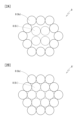
- FIGS. 2A and 2B are cross-sectional views showing raw material twisted wires for forming an electric wire conductor having a flat shape.
- FIG. 2A shows a raw material stranded wire that is a raw material for the electric wire conductor according to the embodiment of the present disclosure shown in FIG. Shows twisted wires.
- 3A to 3D are photographs showing the wire conductors of Sample A2 and Sample A5 produced in a state in which the twisted structure has been resolved.
- 3A and 3C show samples A2 and A5, respectively, in which the twisted structure of the outer layer is removed in units of child strands
- FIGS. 3B and 3D show samples A2 and A5, respectively, with the outer layer removed and the inner layer This figure shows the state in which the twisted structure of is resolved in child twisted wire units.
- 4A to 4D are photographs of cross sections of conductors of representative samples. Samples A2, A5, B2, and B5 are shown, respectively.
- 5A and 5B are diagrams showing the relationship between wire ratio and repulsive force. 5A shows the case where the aspect ratio is 5, and FIG. 5B shows the case where the aspect ratio is 6.
- the electric wire conductor according to the present disclosure is configured as a stranded wire including a plurality of child strands made by twisting a plurality of strands, and a cross section of the stranded wire intersecting the axial direction has a width dimension and a height dimension.
- the flat part has a flattened shape larger than , the number of outer layer strands is the number of outer layer strands, and the total number of the strands constituting the inner layer strands arranged inside the outer layer strands is the number of inner layer strands, and the number of outer layer strands relative to the number of inner layer strands.
- the ratio is 2.0 or more.
- the ratio of the number of outer layer strands to the number of inner layer strands is 2.0 or more.
- the number of strands forming the inner portion is reduced to 1/2 or less compared to the number of strands forming the outer peripheral portion of the electric wire conductor. Because the number of strands placed inside the wire conductor is reduced, when the wire conductor is deformed into a flat shape by applying force to form a flat part, the wires located inside the wire conductor are In this case, deformation due to the application of a large load is less likely to occur.
- the wire conductor has high flexibility.
- the number of the strands constituting each of the plurality of child strands is the same, and the ratio of the number of the outer layer child strands to the number of the inner layer child strands is 2.0 or more. good. Then, by using the same child stranded wires throughout the wire conductor and setting the number of child strands placed on the outer periphery and inner portion of the wire conductor, the number of strands composing the inner portion can be reduced as described above. , it is possible to obtain a wire conductor having high flexibility in the flat portion.
- the ratio of the number of outer layer strands to the number of inner layer strands is preferably 3.0 or more. This makes it particularly easy to increase the flexibility of the wire conductor.
- the flexibility of the electric wire conductor can be effectively improved by reducing the number of wires forming the inner layer compared to the case where the inner layer stranded wires are arranged in two layers or even more layers. be able to.
- the dimension in the width direction is preferably five times or more the dimension in the height direction. This makes it possible to reduce the height occupied by the wire conductor and improve space saving.
- the more flat a wire conductor is formed the greater the load is applied to the wires constituting the inner part, which tends to reduce the flexibility of the wire conductor. If the number ratio is set to 2.0 or more, high flexibility can be ensured even when such a highly flat shape is adopted.
- the insulated wire according to the present disclosure includes the wire conductor and an insulating coating that covers the outer periphery of the wire conductor. Further, a wire harness according to the present disclosure includes the insulated wire. These insulated wires and wire harnesses include the above-mentioned wire conductor, which has high flexibility because the number of strands arranged inside the wire conductor is kept small. Therefore, the high flexibility of the insulated wire and wire harness as a whole can be utilized.
- FIG. 1 schematically shows a cross-sectional view of a wire conductor 1 according to an embodiment of the present disclosure.
- the electric wire conductor 1 is configured as a stranded wire in which a plurality of wires 3 are twisted together.
- the electric wire conductor 1 has a flat outer shape at least in a portion along the axial direction.
- the wire conductor 1 has a flat portion in which a cross section perpendicularly intersecting the axial direction of the wire conductor 1 has a flat shape.
- the entire axial direction of the electric wire conductor 1 is treated as such a flat portion.
- the fact that the cross section of the wire conductor 1 has a flat shape refers to the dimension of the longest straight line among the straight lines that cross the cross section in parallel with the sides or diameters that make up the cross section and include the entire cross section.
- a state in which the width w is larger than the height h, which is the dimension of a straight line that is perpendicular to the straight line and includes the entire cross section.
- the cross section of the wire conductor 1 may have any specific shape as long as it has a flat shape.
- the flat shape include a rectangle, an ellipse, an oval, an oval (a rectangle with semicircles at both ends), a parallelogram, and a trapezoid. If the circumscribed figure of the cross section can be approximated to each of these shapes, it can be considered that the cross-sectional shape of the electric wire conductor 1 takes each shape.
- the wire conductor 1 has a cross-sectional shape that can be approximated to an oval shape.
- each child strand 2 is simplified by a circle or an ellipse with a solid line (outer layer strand 2o) and a broken line (inner layer child strand 2i), and is surrounded by a rectangle.
- the cross-sectional view shown in exemplifies the structure of a child strand 2 including a plurality of strands 3.
- the plurality of child stranded wires 2 may simply be assembled into a bundle, but it is preferable that the plurality of child stranded wires 2 have a parent-twisted structure in which the plurality of child stranded wires 2 are mutually twisted.
- Each child strand 2 may have a cross-section that can be approximated to a circle, or may have a cross-section that is deformed from a circle.
- FIG. 1 shows a form in which the child twisted wires (inner layer child twisted wires) 2i on the inner side of the cross section are deformed into a flat shape.
- the electric wire conductor 1 can be formed by rolling a raw material stranded wire in which a plurality of child stranded wires 2 are twisted together to have a substantially circular cross section. Due to the shaping into a flat shape, the cross-sectional shape of at least a portion of the child strands 2 and each strand 3 constituting the electric wire conductor 1 may be deformed from a circular shape. The rate of deformation of the child strands 2 and the strands 3 from the circular shape is often smaller at the outer periphery of the cross section of the electric wire conductor 1, particularly at regions on both sides in the width direction, than at the inner region. In the wire conductors of the examples shown in FIGS. 4A to 4D, the deformation rate of the strands on both sides in the width direction is also small.
- the electric wire including the electric wire conductor 1 according to the present embodiment has a flat cross section, so that the wire conductor 1 has a flat cross section, so that the wire conductor 1 has a flat cross section, so that the wire conductor 1 has a substantially circular cross section.
- the space required can be reduced. In other words, it is possible to reduce the space around a certain electric wire in which other electric wires or other members cannot be arranged. In particular, the space occupied by the electric wires in the height direction can be reduced, making it easy to achieve space saving.
- the wire conductor 1 is made of a stranded wire in which a plurality of wires 3 are twisted together, it has higher flexibility than a single wire flat conductor having the same conductor cross-sectional area.
- the wire conductor 1 exhibits high flexibility, especially in the height direction. Since the electric wire conductor 1 has a flat shape in this way, it achieves both high space saving and flexibility. Insulated wires and wire harnesses containing the wire conductor 1 are highly space-saving and flexible, so they are particularly suitable for use in applications that require wiring in narrow spaces or complicated routes, such as in automobiles. I can do it.
- the width in the cross section of the wire conductor 1 is three times or more the height. That is, it is preferable that the aspect ratio w/h is 3 or more. The aspect ratio is more preferably 5 or more. Although there is no particular upper limit to the flatness ratio of the electric wire conductor 1, it is kept to about 8 or less from the viewpoint of avoiding applying excessive load to the electric wire conductor 1 as it is formed into a flat shape. It's good to keep it.
- the material constituting the wire conductor 1 is not particularly limited, and various metal materials can be used.
- Typical metal materials constituting the wire conductor 1 include copper and copper alloys, as well as aluminum and aluminum alloys.
- the cross-sectional area of the conductor tends to be large in order to ensure the necessary electrical conductivity. Therefore, the effect of flattening the electric wire conductor 1 to improve space saving is increased.
- the larger the conductor cross-sectional area the greater the effect of ensuring flexibility by reducing the number of strands 3 included in the inner layer, as will be described later. From these points of view, it is preferable that the wire conductor 1 is made of aluminum or an aluminum alloy.
- the conductor cross-sectional area is 16 mm 2 or more. Because the electric wire conductor 1 is configured as an aggregate of a plurality of child strands 2 instead of twisting together a plurality of strands 3, even if the conductor cross-sectional area is large, the strands can be The twisting and forming into a flat shape can be performed efficiently. Although there is no particular upper limit to the cross-sectional area of the conductor, it is preferably kept to 300 mm 2 or less, for example, from the viewpoint of ensuring bending flexibility.
- the outer diameter of the wire 3 constituting the electric wire conductor 1 is not particularly limited, but can be exemplified in a range of 0.12 mm or more and 0.5 mm or less. It is preferable that each strand 3 constituting the electric wire conductor 1 is made of the same thing, that is, the same material, and has the same outer diameter.
- An insulated wire according to an embodiment of the present disclosure includes a wire conductor 1 and an insulation coating (not shown).
- the insulation coating covers the entire outer periphery of the wire conductor 1.
- the material constituting the insulating coating is not particularly limited as long as it is an insulating material, but it is preferably one based on an organic polymer.
- organic polymers include olefin polymers such as polyolefins and olefin copolymers, halogen polymers such as polyvinyl chloride, various elastomers, and rubbers.
- the organic polymer may be crosslinked or foamed.
- the insulating coating may contain various additives such as flame retardants in addition to the organic polymer.
- the insulating coating is formed as an extrusion.
- the insulated wire according to the embodiment of the present disclosure may be used alone or as a component of the wire harness according to the embodiment of the present disclosure.
- a wire harness according to an embodiment of the present disclosure includes an insulated wire according to an embodiment of the present disclosure.
- the wire harness may include a plurality of insulated wires according to the embodiments of the present disclosure, or may include other types of insulated wires in addition to the insulated wires according to the embodiments of the present disclosure.
- a plurality of insulated wires according to the embodiments of the present disclosure are arranged in the width direction and/or height direction.
- the specific arrangement structure of the plurality of insulated wires is not particularly limited, but as a preferred form, the plurality of insulated wires are arranged in the width direction and fused to a common sheet material.
- Examples of fixing methods include the following. In this case, it is particularly preferable that the heights of the plurality of lined up insulated wires are the same.
- the electric wire conductor 1 is configured to include a plurality of child strands 2 in which a plurality of strands 3 are twisted together.
- the plurality of child twisted wires 2 are arranged in layers.
- the phrase "a plurality of child strands 2 are arranged in a layer” means that a plurality of child strands 2 are arranged in a substantially circular shape in a plurality of layers along the direction connecting the outer peripheral part and the center part of the electric wire conductor 1. (The same applies below to the case where the number of layers in the arrangement of the child strands 2 is defined).
- the substantially annular arrangement includes the arrangement of one piece alone and the arrangement linearly in the width direction.
- the child strands 2 arranged on the outer periphery of the flat cross section constitute the outer layer as the outer layer child strands 2o.
- the child strands 2 arranged inside the outer layer child strands 2o in the cross section constitute the inner layer as the inner layer child strands 2i. All of the child strands 2 existing inside the outer layer child strands 2o become inner layer child strands 2i.
- the outer layer is composed of only one layer of outer layer twisted wires 2o.
- the inner layer may be composed of only one inner layer twisted wire 2i, or may be composed of a plurality of inner layer twisted wires 2i.
- Each child strand 2 constituting the electric wire conductor 1 can be clearly confirmed by visually observing each child strand 2 as a unit while untwisting the electric wire conductor 1, as shown in FIGS. 3A to 3D, for example. can do. If the wire conductor 1 has a parent twist structure, the parent twist structure may be eliminated. If the wire conductor 1 is untwisted in units of child strands 2, as shown in FIGS. 3A to 3D, the outer layer strands 2o and the inner layer strands 2i can be distinguished, and the inner layer strands 2i can be distinguished. In the case where there are multiple layers, each layer can also be clearly distinguished.
- the ratio of the number of strands 3 forming the outer layer to the strands 3 forming the inner layer is within a predetermined range.
- the total number of strands 3 constituting the outer layer stranded wire 2o that is, the total number of strands 3 included in the outer layer is defined as the number of outer layer strands (N o )
- the number of strands 3 constituting the inner layer strand 2i is defined as the number of inner layer strands (N i ).
- the ratio (N o /N i ) of the number N o of outer layer strands to the number N i of inner layer strands is defined as the strand ratio.
- this strand ratio is 2.0 or more.
- the number of strands 3 constituting the inner layer is less than half the number of strands 3 constituting the outer layer.
- the wire conductor 1 when a wire conductor adopts a child-twisted structure, the number of strands constituting each of a plurality of child strands is the same, and the wire conductor 1 according to the present embodiment also has a plurality of It is preferable to make the number of strands 3 constituting each of the child strands 2 the same from the viewpoint of simplicity of the structure of the electric wire conductor 1.
- the ratio of the number of outer layer twisted wires 2o to the number of inner layer twisted wires 2i becomes equal to the strand ratio. That is, in the electric wire conductor 1 according to this embodiment, the ratio of the number of outer layer strands 2o to the number of inner layer strands 2i is 2.0 or more.
- the number of strands 3 constituting each of the plurality of child strands 2 is the same.
- the number of outer layer stranded wires 2o is 12 and the number of inner layer stranded wires 2i is 4, and their ratio, that is, the strand ratio, is 12/4, which is 3. .
- the strand ratio is 2.0 or more, and the number of strands 3 constituting the inner layer is kept small. Therefore, in the inner portion of the wire conductor 1, the packing density of the strands 3 is suppressed to a low level, and gaps are easily secured between the strands 3. As a result, when the electric wire conductor 1 is bent, the strands 3 can easily move inside the electric wire conductor 1, and high flexibility can be obtained in the electric wire conductor 1.
- forming the wire conductor 1 into a flat shape is a raw material stranded wire 9 in which a plurality of child stranded wires 8 are twisted together to have a substantially circular cross section (or a substantially hexagonal cross section; the same applies hereinafter) as shown in FIG. 2A.
- the effect of improving flexibility is enhanced by setting the strand ratio to 2.0 or more.
- the inner part where a large number of strands are densely arranged in a limited space than the outer periphery of the wire conductor a large load is likely to be applied to the wire.
- the wires on the inside of the wire conductor are deformed and crowded together, and the deformed shapes of the wires fit into each other, creating a state in which the wires are in close contact with each other. Easy to form. In this manner, when the wires are closely packed and in close contact with each other, relative movement of the wires is less likely to occur.
- the material that makes up the wire is likely to harden (work hardening). As a result of the limited relative movement of these strands and the hardening of the material, the wire conductor becomes less flexible.
- the electric wire conductor 1 since the number of strands in the inner layer is suppressed to 2.0 or less in terms of strand ratio, even if force is applied by rolling etc. during flattening, in the inner layer, The force applied to each wire 3 is suppressed to a low level, and the crowding and adhesion of the wires 3 and the degree of hardening of the constituent materials are reduced. As a result, the flexibility of the wire conductor 1 is maintained, and it becomes possible to bend and deform the wire conductor 1 flexibly.
- the wire ratio is set to 2.0 or more, and the number of inner layer wires is suppressed to be smaller than the number of outer layer wires, so that the wire conductor 1 of the wire 3 is High flexibility can be obtained from both the effect of having a high degree of freedom in relative movement and the effect of suppressing hardening due to deformation of the strands 3.
- the strand ratio is 2.5 or more, more preferably 3.0 or more.
- the flatness ratio w/h of the flat shape of the electric wire conductor 1 is preferably 3 or more, more preferably 5 or more, but if the strand ratio is set to 2.0 or more, such a high flatness can be achieved. Even when the wire conductor 1 is molded into the shape of , high flexibility of the wire conductor 1 can be ensured.
- the upper limit of the wire ratio is not particularly determined, for example, a configuration in which the wire ratio is 3.5 or less can be exemplified.
- priority is given to improving the flexibility of the electric wire conductor 1, it is also preferable to have a strand ratio of 3.0 or more; however, if priority is given to maintaining a stable flat shape in addition to a certain degree of flexibility, It is preferable to keep the linear ratio to about 3.0 or less.
- the arrangement of the child strands 8 in the raw material strands 9 is carried over to the flattened electric wire conductor 1. That is, in the raw material stranded wire 9 shown in FIG. 2A, the raw material outer layer stranded wire 8o located on the outer periphery and the raw material inner layer stranded wire 8i located inside the raw material outer layer stranded wire 8o are each In the wire conductor 1 after flattening, it becomes an outer layer stranded wire 2o and an inner layer stranded wire 2i.
- the number of raw material outer layer strands 8o and raw material inner layer strands 8i in the raw material stranded wire 9 may be set in accordance with the desired strand ratio in the flattened electric wire conductor 1.
- the ratio of the number of raw material inner layer strands 8i to the number of raw material outer layer strands 8o is the same as the ratio of the number of inner layer strands 2i to the number of outer layer strands 2o in the wire conductor 1 after flattening.
- the ratio directly becomes the strand ratio in the electric wire conductor 1.
- FIG. 2A shows a raw material stranded wire 9' made of a conventional general electric wire conductor with a substantially circular cross section, in which child stranded wires 8 are packed close-packed in a concentric layer.
- the raw material inner layer child strands 8i there are a total of seven child strands, including one child strand 8 placed in the center and six child strands 8 placed around the outside in close-packed manner. Contains strands 8. Further, as the raw material outer layer child strands 8o, 12 child strands 8 arranged around the outer periphery in a close-packed manner are further included. When this raw material stranded wire 9' is deformed into a flat shape, there will be 12 outer layer stranded wires 2o and 7 inner layer stranded wires 2i, resulting in a wire ratio of 12/7, which is 1.71. This wire ratio is less than 2.0.
- such wire conductors with a strand ratio of less than 2.0 tend to have low flexibility.
- a conventional electric wire conductor in which child stranded wires 8 are arranged in a close-packed manner is used as the raw material stranded wire 9' and flattened, it is difficult to obtain high flexibility.
- the inner layer may be composed of only one layer of inner layer twisted wires 2i, or may be composed of a plurality of inner layer twisted wires 2i.
- the layer structure of the child strands 2 in the electric wire conductor 1 is defined as "a- b-c".
- a is the number of twisted child wires 2 that constitute the inner layer of the two inner layers
- b is the number of twisted child wires 2 that constitute the outer layer of the two inner layers
- c is the number of twisted child wires 2 that constitute the outer layer.
- the layer structure is expressed in this way, the number of inner layer twisted wires 2i is a+b, and the ratio of the number of outer layer twisted wires 2o to the number of inner layer twisted wires 2i, that is, the strand ratio is c/( a+b).
- the layer structure of the electric wire conductor 1 shown in FIG. 1, which is formed from the raw material stranded wire 9 shown in FIG. 2A, is expressed as "0-4-12".
- the layer structure of the electric wire conductor formed from the raw material stranded wire 9' shown in FIG. 2B is expressed as "1-6-12".
- the flattened electric wire conductor 1 is shown in FIG. 1 and the raw material stranded wire 9 is shown in FIG. ), that is, a configuration having a layer structure of "0-bc" is preferable.
- the strand ratio can be easily lowered by reducing the number of inner layer stranded wires 2i, and the flexibility of the wire conductor 1 can be effectively increased.
- the inner layer is composed of a plurality of layers of inner layer child twisted wires 2o, it is preferable to keep the number of layers to two.
- the inner layer of the two-layer structure has a layer structure in which a plurality of inner layer twisted wires 2i are arranged around the outer periphery of one inner layer twisted wire 2i, that is, a layer structure of "1-b-c".
- the form is preferred.
- the values of b and c are not particularly specified, and may be set appropriately in consideration of the necessary cross-sectional area of the conductor, etc., but a range of 4 or more and 6 or less can be suitably adopted as b. . Moreover, in that case, as c, a range of 8 or more and 12 or less can be suitably adopted.
- Particularly suitable layer configurations include "0-4-8", "0-6-12", “0-4-12”, etc. In particular, a layer structure of "0-4-12" is preferred.
- the electric wire conductor 1 has high flexibility by keeping the number of strands 3 constituting the inner layer small so that the strand ratio is 2.0 or more.
- the flexibility of the electric wire conductor 1 can be evaluated, for example, by the repulsive force when the electric wire conductor 1 is bent. It is shown that the smaller the repulsive force generated when the wire conductor 1 is bent at a predetermined bending radius, the higher the flexibility of the wire conductor 1.
- the repulsive force of the electric wire conductor 1 (conductor of interest) according to the focused embodiment of the present disclosure may cause a raw material stranded wire 9' packed with child stranded wires 8 as shown in FIG. 2B to have a flat shape.
- the repulsion force be smaller than that of a reference conductor obtained by molding. It is more preferable that the repulsive force of the conductor of interest is 99% or less, more preferably 95% or less, 90% or less, or 85% or less of the repulsive force of the reference conductor.
- the reference conductor may be formed by forming a raw material stranded wire having a close-packed structure made of the same material as the conductor of interest and having the same conductor cross-sectional area into a flat shape having the same aspect ratio as the conductor of interest.
- the repulsive force may be measured using an insulated wire in which the reference conductor and the target conductor are coated with an insulating coating of the same material and thickness, and the two may be compared. Since the insulation coating usually has higher flexibility than the wire conductor, the contribution of the insulation coating can be ignored when comparing repulsion forces.
- the improvement in flexibility by increasing the strand ratio is achieved by ensuring ease of relative movement of the strands 3 and suppressing hardening of the strands 3, as described above. This is achieved through the effects of both.
- the degree of hardening of the wire 3 is reflected in the conductor resistance of the wire conductor 1.
- conductor resistance In copper and copper alloys, as well as in aluminum and aluminum alloys, conductor resistance often increases when work hardening occurs. Therefore, it can be evaluated that as the conductor resistance increases, the degree of hardening of the wire 3 due to application of load in the electric wire conductor 1 increases.
- the amount of increase in conductor resistance compared to the raw material stranded wire 9 is suppressed to 22% or less, more preferably 18% or less. Further, it is preferable that the conductor resistance of the electric wire conductor 1 is smaller than the conductor resistance of the reference conductor.
- the outer diameter of the strands was adjusted according to the number of strands (number of child strands) so that the conductor cross-sectional area was equal to 62.0 ⁇ 0.6 mm 2 in the raw stranded state. It was set.
- the flatness ratio of the electric wire conductor was controlled by the magnitude of the force applied from the roller to the raw material stranded wire, and the flatness ratio was 5 for samples A1 to A5 and 6 for samples B1 to B5.
- An insulating coating was formed on the outer periphery of each wire conductor produced above to produce an insulated wire.
- the insulation coating polyolefin was used as the material, and a coating layer having a thickness of 0.6 mm was formed by extrusion molding.
- a cross-sectional sample was created by embedding the insulated wire of each sample in acrylic resin and cutting it in a cross section perpendicular to the axial direction. By observing this cross-sectional sample, it was confirmed that the wire conductor was formed into a flat shape having a predetermined aspect ratio. In addition, the conductor cross-sectional area was determined from the conductor weight.
- the insulated wire of each sample was cut out to a length of 400 mm, and both ends were held with a gripping tool to bend the insulated wire. At this time, the bending radius (R) was set to 40 mm, and the load applied to the end of the insulated wire was measured with a load cell attached to the gripping tool while the wire was bent to 135 degrees. This load measurement was recorded as the repulsion force.
- FIGS. 3A to 3D show photographs of these samples taken in a state in which the twisted structure was resolved in units of child twisted wires.
- 3A and 3B are images of sample A2
- FIGS. 3C and 3D are images of sample A5.
- 3A and 3C show a state in which the twisted structure of the outer layer is removed
- FIGS. 3B and 3D show a state in which the outer layer is completely removed and the twisted structure of the inner layer is removed.
- samples A2, A5, B2, and B5 as representative samples.
- Samples A2 and B2 have a layer structure of "1-6-12”
- samples A5 and B5 have a layer structure of "0-4-12”.
- the flatness ratio was set to 5 in samples A2 and A5, and the flatness ratio was set to 6 in samples B2 and B5.
- Figures 4A to 4D show cross-sectional photographs of the samples A2, A5, B2, and B5, respectively.
- the wire conductor is formed into a flat shape having a predetermined flatness ratio. It is confirmed that in any of the wire conductors, the strands in the inner region are significantly deformed compared to the outer peripheral portion, particularly the regions on both sides in the width direction.
- the degree of deformation of the strands in the inner part is smaller, and gaps are ensured between the strands in the inner part. You can see that.
- the strand ratio of the electric wire conductor was 1.71 (12/7) for samples A2 and B2, and 3 (12/4) for samples A5 and B5.
- the above tendency confirmed in the cross-sectional photographs shows that by increasing the wire ratio and reducing the number of wires in the inner layer relative to the outer layer, deformation and high density of wires in the inner layer can be alleviated. It shows. It was confirmed that each sample other than the above-mentioned samples A2, A5, B2, and B5 had a similar tendency.
- Tables 1 and 2 show the layer structure, wire ratio, and results of each evaluation for samples A1 to A5 with a flatness ratio of 5 and samples B1 to B5 with a flatness ratio of 6, respectively.
- the rate of change from the raw material stranded wire is also shown in parentheses.
- FIGS. 5A and 5B illustrate the relationship between the strand ratio and the repulsive force for samples A1 to A5 and samples B1 to B5, respectively. Approximate straight lines are also shown in the figure.
- the sample number is written near each plot point.
- the magnitude of conductor resistance is an index that reflects the load applied to the wire conductor due to processing during flattening and the degree of hardening of the wire due to it. This indicates that the degree of hardening is small. In other words, the hardening of the strands is reduced in areas where the strand ratio is large, and this, together with the effect of the relative movement of the strands, can be said to contribute to improved flexibility. .
- the conductor resistance of the raw material stranded wire is 0.43 m ⁇ /m, and in all samples, the conductor resistance of the wire conductor after flattening has increased from the state of the raw material stranded wire, but the wire ratio is In large samples, the increase is suppressed to a small extent.
Landscapes
- Insulated Conductors (AREA)
- Non-Insulated Conductors (AREA)
Priority Applications (5)
| Application Number | Priority Date | Filing Date | Title |
|---|---|---|---|
| DE112023001393.4T DE112023001393T5 (de) | 2022-03-15 | 2023-03-07 | Elektrischer drahtleiter, isolierter elektrischer draht und verdrahtung |
| CN202380025689.0A CN118786490A (zh) | 2022-03-15 | 2023-03-07 | 电线导体、绝缘电线及线束 |
| JP2024507778A JP7704296B2 (ja) | 2022-03-15 | 2023-03-07 | 電線導体、絶縁電線、およびワイヤーハーネス |
| US18/841,993 US20250174373A1 (en) | 2022-03-15 | 2023-03-07 | Electric wire conductor, insulated electric wire, and wiring harness |
| JP2025106957A JP2025123544A (ja) | 2022-03-15 | 2025-06-25 | 電線導体、絶縁電線、およびワイヤーハーネス |
Applications Claiming Priority (2)
| Application Number | Priority Date | Filing Date | Title |
|---|---|---|---|
| JP2022040578 | 2022-03-15 | ||
| JP2022-040578 | 2022-03-15 |
Publications (1)
| Publication Number | Publication Date |
|---|---|
| WO2023176575A1 true WO2023176575A1 (ja) | 2023-09-21 |
Family
ID=88023118
Family Applications (1)
| Application Number | Title | Priority Date | Filing Date |
|---|---|---|---|
| PCT/JP2023/008492 Ceased WO2023176575A1 (ja) | 2022-03-15 | 2023-03-07 | 電線導体、絶縁電線、およびワイヤーハーネス |
Country Status (5)
| Country | Link |
|---|---|
| US (1) | US20250174373A1 (https=) |
| JP (2) | JP7704296B2 (https=) |
| CN (1) | CN118786490A (https=) |
| DE (1) | DE112023001393T5 (https=) |
| WO (1) | WO2023176575A1 (https=) |
Cited By (1)
| Publication number | Priority date | Publication date | Assignee | Title |
|---|---|---|---|---|
| WO2025205300A1 (ja) * | 2024-03-29 | 2025-10-02 | 株式会社オートネットワーク技術研究所 | 電線導体、絶縁電線、およびワイヤーハーネス |
Citations (2)
| Publication number | Priority date | Publication date | Assignee | Title |
|---|---|---|---|---|
| JPS61182208A (ja) * | 1985-02-07 | 1986-08-14 | Toshiba Corp | 高圧発生装置 |
| WO2019093309A1 (ja) * | 2017-11-08 | 2019-05-16 | 株式会社オートネットワーク技術研究所 | 電線導体、被覆電線、ワイヤーハーネス |
-
2023
- 2023-03-07 DE DE112023001393.4T patent/DE112023001393T5/de active Pending
- 2023-03-07 JP JP2024507778A patent/JP7704296B2/ja active Active
- 2023-03-07 US US18/841,993 patent/US20250174373A1/en active Pending
- 2023-03-07 WO PCT/JP2023/008492 patent/WO2023176575A1/ja not_active Ceased
- 2023-03-07 CN CN202380025689.0A patent/CN118786490A/zh active Pending
-
2025
- 2025-06-25 JP JP2025106957A patent/JP2025123544A/ja active Pending
Patent Citations (2)
| Publication number | Priority date | Publication date | Assignee | Title |
|---|---|---|---|---|
| JPS61182208A (ja) * | 1985-02-07 | 1986-08-14 | Toshiba Corp | 高圧発生装置 |
| WO2019093309A1 (ja) * | 2017-11-08 | 2019-05-16 | 株式会社オートネットワーク技術研究所 | 電線導体、被覆電線、ワイヤーハーネス |
Cited By (1)
| Publication number | Priority date | Publication date | Assignee | Title |
|---|---|---|---|---|
| WO2025205300A1 (ja) * | 2024-03-29 | 2025-10-02 | 株式会社オートネットワーク技術研究所 | 電線導体、絶縁電線、およびワイヤーハーネス |
Also Published As
| Publication number | Publication date |
|---|---|
| JP2025123544A (ja) | 2025-08-22 |
| US20250174373A1 (en) | 2025-05-29 |
| JP7704296B2 (ja) | 2025-07-08 |
| JPWO2023176575A1 (https=) | 2023-09-21 |
| DE112023001393T5 (de) | 2024-12-24 |
| CN118786490A (zh) | 2024-10-15 |
Similar Documents
| Publication | Publication Date | Title |
|---|---|---|
| JP7290184B2 (ja) | 電線導体、被覆電線、ワイヤーハーネス、および電線導体の製造方法 | |
| JP4804860B2 (ja) | 複合撚線導体 | |
| JP2012119073A (ja) | 絶縁電線用撚線導体 | |
| JP6893496B2 (ja) | 同軸ケーブル | |
| JP2025123544A (ja) | 電線導体、絶縁電線、およびワイヤーハーネス | |
| JP6775283B2 (ja) | 耐屈曲電線及びワイヤハーネス | |
| JP7658285B2 (ja) | 同軸ケーブル | |
| JP7468265B2 (ja) | ケーブル | |
| JP2007317477A (ja) | 撚線導体 | |
| CN214588110U (zh) | 电缆 | |
| JP7582138B2 (ja) | ケーブル | |
| JP2025154083A (ja) | 電線導体、絶縁電線、およびワイヤーハーネス | |
| JP7456245B2 (ja) | ワイヤーハーネス | |
| JP4866545B2 (ja) | ケーブルおよび撚合せ型ケーブル | |
| JP2006031954A (ja) | 耐屈曲シールド構造及びケーブル | |
| JP2023146624A (ja) | 電線、及びケーブル | |
| JP2023022407A (ja) | 多芯ケーブル | |
| JP6979796B2 (ja) | 多芯ケーブル | |
| CN116997979A (zh) | 绝缘电线及线束 | |
| JP7725999B2 (ja) | 絶縁電線およびワイヤーハーネス | |
| JP7316838B2 (ja) | 撚線導体および被覆電線 | |
| WO2023189982A1 (ja) | 絶縁電線、ワイヤーハーネス、および絶縁電線の製造方法 | |
| JP2021111555A (ja) | 同軸ケーブル | |
| JP2015057787A (ja) | 絶縁電線用撚線導体 | |
| JP2005197106A (ja) | 電線及び電線用導体 |
Legal Events
| Date | Code | Title | Description |
|---|---|---|---|
| 121 | Ep: the epo has been informed by wipo that ep was designated in this application |
Ref document number: 23770531 Country of ref document: EP Kind code of ref document: A1 |
|
| WWE | Wipo information: entry into national phase |
Ref document number: 18841993 Country of ref document: US |
|
| WWE | Wipo information: entry into national phase |
Ref document number: 202380025689.0 Country of ref document: CN |
|
| ENP | Entry into the national phase |
Ref document number: 2024507778 Country of ref document: JP Kind code of ref document: A |
|
| WWE | Wipo information: entry into national phase |
Ref document number: 112023001393 Country of ref document: DE |
|
| 122 | Ep: pct application non-entry in european phase |
Ref document number: 23770531 Country of ref document: EP Kind code of ref document: A1 |
|
| WWP | Wipo information: published in national office |
Ref document number: 18841993 Country of ref document: US |