WO2023189982A1 - 絶縁電線、ワイヤーハーネス、および絶縁電線の製造方法 - Google Patents
絶縁電線、ワイヤーハーネス、および絶縁電線の製造方法 Download PDFInfo
- Publication number
- WO2023189982A1 WO2023189982A1 PCT/JP2023/011349 JP2023011349W WO2023189982A1 WO 2023189982 A1 WO2023189982 A1 WO 2023189982A1 JP 2023011349 W JP2023011349 W JP 2023011349W WO 2023189982 A1 WO2023189982 A1 WO 2023189982A1
- Authority
- WO
- WIPO (PCT)
- Prior art keywords
- flat
- conductor
- wire
- insulated wire
- shape
- Prior art date
Links
- 238000004519 manufacturing process Methods 0.000 title claims abstract description 26
- 238000000034 method Methods 0.000 title claims description 13
- 239000004020 conductor Substances 0.000 claims abstract description 123
- 230000002093 peripheral effect Effects 0.000 claims abstract description 34
- 239000002994 raw material Substances 0.000 claims description 39
- 238000000576 coating method Methods 0.000 claims description 32
- 239000011248 coating agent Substances 0.000 claims description 31
- 238000005452 bending Methods 0.000 description 42
- 238000009413 insulation Methods 0.000 description 12
- 238000009826 distribution Methods 0.000 description 6
- 230000001965 increasing effect Effects 0.000 description 5
- 238000010586 diagram Methods 0.000 description 3
- 238000011156 evaluation Methods 0.000 description 3
- 239000000463 material Substances 0.000 description 3
- 238000005259 measurement Methods 0.000 description 3
- 229910000838 Al alloy Inorganic materials 0.000 description 2
- 230000008901 benefit Effects 0.000 description 2
- 230000008859 change Effects 0.000 description 2
- 230000000694 effects Effects 0.000 description 2
- 238000001125 extrusion Methods 0.000 description 2
- 238000013001 point bending Methods 0.000 description 2
- 238000012545 processing Methods 0.000 description 2
- 238000012360 testing method Methods 0.000 description 2
- 239000004925 Acrylic resin Substances 0.000 description 1
- 229920000178 Acrylic resin Polymers 0.000 description 1
- RYGMFSIKBFXOCR-UHFFFAOYSA-N Copper Chemical compound [Cu] RYGMFSIKBFXOCR-UHFFFAOYSA-N 0.000 description 1
- 229910000881 Cu alloy Inorganic materials 0.000 description 1
- 229910052782 aluminium Inorganic materials 0.000 description 1
- XAGFODPZIPBFFR-UHFFFAOYSA-N aluminium Chemical compound [Al] XAGFODPZIPBFFR-UHFFFAOYSA-N 0.000 description 1
- 230000015572 biosynthetic process Effects 0.000 description 1
- 239000000470 constituent Substances 0.000 description 1
- 229910052802 copper Inorganic materials 0.000 description 1
- 239000010949 copper Substances 0.000 description 1
- 229920003020 cross-linked polyethylene Polymers 0.000 description 1
- 239000004703 cross-linked polyethylene Substances 0.000 description 1
- 230000007850 degeneration Effects 0.000 description 1
- 230000006866 deterioration Effects 0.000 description 1
- 230000002708 enhancing effect Effects 0.000 description 1
- 238000010438 heat treatment Methods 0.000 description 1
- 229910052751 metal Inorganic materials 0.000 description 1
- 239000002184 metal Substances 0.000 description 1
- 238000001000 micrograph Methods 0.000 description 1
- 238000012986 modification Methods 0.000 description 1
- 230000004048 modification Effects 0.000 description 1
- 238000009828 non-uniform distribution Methods 0.000 description 1
- 238000002360 preparation method Methods 0.000 description 1
- 230000008569 process Effects 0.000 description 1
- 239000011342 resin composition Substances 0.000 description 1
- 230000004044 response Effects 0.000 description 1
- 238000005482 strain hardening Methods 0.000 description 1
Images


Classifications
-
- H—ELECTRICITY
- H01—ELECTRIC ELEMENTS
- H01B—CABLES; CONDUCTORS; INSULATORS; SELECTION OF MATERIALS FOR THEIR CONDUCTIVE, INSULATING OR DIELECTRIC PROPERTIES
- H01B13/00—Apparatus or processes specially adapted for manufacturing conductors or cables
-
- H—ELECTRICITY
- H01—ELECTRIC ELEMENTS
- H01B—CABLES; CONDUCTORS; INSULATORS; SELECTION OF MATERIALS FOR THEIR CONDUCTIVE, INSULATING OR DIELECTRIC PROPERTIES
- H01B7/00—Insulated conductors or cables characterised by their form
-
- H—ELECTRICITY
- H01—ELECTRIC ELEMENTS
- H01B—CABLES; CONDUCTORS; INSULATORS; SELECTION OF MATERIALS FOR THEIR CONDUCTIVE, INSULATING OR DIELECTRIC PROPERTIES
- H01B7/00—Insulated conductors or cables characterised by their form
- H01B7/04—Flexible cables, conductors, or cords, e.g. trailing cables
-
- H—ELECTRICITY
- H01—ELECTRIC ELEMENTS
- H01B—CABLES; CONDUCTORS; INSULATORS; SELECTION OF MATERIALS FOR THEIR CONDUCTIVE, INSULATING OR DIELECTRIC PROPERTIES
- H01B7/00—Insulated conductors or cables characterised by their form
- H01B7/08—Flat or ribbon cables
Definitions
- the present disclosure relates to an insulated wire, a wire harness, and a method for manufacturing an insulated wire.
- Flat cables constructed using flat conductors are known. By using a flat cable, the space occupied during wiring can be reduced compared to the case where a general electric wire having a conductor with a substantially circular cross section is used.
- Patent Documents 1 and 2 In conventional flat cables, rectangular conductors are often used as conductors, as disclosed in Patent Documents 1 and 2.
- a rectangular conductor is a single metal wire formed into a rectangular cross section.
- Patent Documents 3 to 5 filed by the applicants disclose electric wire conductors in which a stranded wire made by twisting a plurality of wires is formed into a flat shape from the viewpoint of achieving both flexibility and space saving. There is.
- a flat conductor having a flat twisted wire conductor in which a plurality of wires are twisted together is also disclosed in Patent Document 6.
- an insulated wire having a flat stranded wire formed into a flat shape as a conductor is excellent in both space saving and flexibility.
- an insulated wire including the flat stranded wire can be suitably used for wiring in various spaces such as narrow spaces.
- flat stranded wires exhibit extremely high flexibility in bending in the height direction (flat direction) of the flat shape, their flexibility in bending in the width direction (edgewise direction) of the flat shape is It tends to be lower than when bending in the direction.
- bending only in the height direction cannot handle the complex bending required in the routing route. There are times when I can't do it.
- an insulated wire whose conductor has a flat cross-section and can be flexibly bent into complex shapes, a wire harness equipped with such an insulated wire, and a manufacturing method that can manufacture such an insulated wire.
- the task is to provide a method.
- the insulated wire of the present disclosure includes a conductor in which a plurality of wires are twisted together, and an insulating coating covering the outer periphery of the conductor, each of the wires constituting the conductor, and
- the insulating coatings are mutually continuous and have a flat part and a reverse flat part along the axial direction of the insulated wire, and in the flat part, the outer shape of the conductor in a cross section perpendicular to the axial direction has a flat shape that is long in the flat direction, and in the reverse flat portion, the outer shape of the conductor in a cross section perpendicular to the axial direction has a flat shape that is long in the reverse flat direction, which is a direction different from the flat direction; In the cross section of both the flat part and the inverted flat part, in the first outer peripheral area, which is a region located in the flat direction with respect to the axial direction, among the parts facing the outer periphery of the conductor, The rate of deformation of the strands from the circular
- the wire harness of the present disclosure includes the insulated wire.
- a conductor is compressed into a flat shape and the outer periphery is coated with an insulating coating.
- the inverted flat part is formed, and the inverted flat part of the raw material flat electric wire is The insulated wire is manufactured by leaving the area other than the area as the flat part.
- An insulated wire, a wire harness, and a method for manufacturing an insulated wire according to the present disclosure provide an insulated wire in which a conductor has a flat cross section and can be flexibly bent into a complicated shape, and an insulated wire including such an insulated wire.
- the present invention provides a manufacturing method for manufacturing wire harnesses and such insulated wires.
- FIG. 1 is a schematic perspective view showing an insulated wire according to an embodiment of the present disclosure.
- FIG. 2 is a sectional view showing the flat portion, corresponding to the AA cross section and the CC cross section in FIG. In the main diagram, the strands are omitted, and the strands are shown in enlarged regions R1 to R3 surrounded by a circle.
- FIG. 3 is a sectional view showing an inverted flat portion, corresponding to the BB cross section in FIG. In the main diagram, the strands are omitted, and the strands are shown in enlarged regions R1 to R3 surrounded by a circle.
- FIG. 4 is a diagram illustrating a method for manufacturing an insulated wire according to an embodiment of the present disclosure, taking the insulated wire shown in FIG.
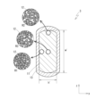
- FIG. 5A to 5C show photographs of the cross sections of actual insulated wires.
- FIG. 5A is a flat wire
- FIG. 5B is a reverse flat wire with a flatness ratio of 1.8
- FIG. 5C is a reverse flat wire with a flatness ratio of 2.8.
- a flat electric wire is shown. The scales of the photos are different from each other.
- An insulated wire according to an embodiment of the present disclosure is an insulated wire having a conductor in which a plurality of wires are twisted together, and an insulating coating covering an outer periphery of the conductor, the wires constituting the conductor.
- the outer shape of the conductor is a flat shape that is long in the flat direction, and in the reverse flat part, the outer shape of the conductor in a cross section perpendicular to the axial direction is a flat shape that is long in the reverse flat direction, which is a direction different from the flat direction.
- a first outer circumferential region that is a region located in the flat direction with respect to the axial direction among the parts facing the outer periphery of the conductor in the cross section of both the flat part and the inverted flat part.
- the rate of deformation of the strands from the circular shape is smaller than in the second outer circumferential region, which is a region located in a direction perpendicular to the flattening direction.
- the above-mentioned insulated wire has a flat part and an inverted flat part in which each conductor has a flat shape, and exhibits high space saving properties.
- the flat part and the reverse flat part exhibit high bending flexibility in the height direction of their respective flat shapes, but the width direction of the flat shapes of the flat part and the reverse flat part are different directions from each other.
- the insulated wire exhibits high bending flexibility in different directions at both locations. In an insulated wire, if you arrange the flat part and the inverted flat part so that the height direction faces the direction in which you want to bend each part, you can bend different parts along the axial direction in one insulated wire.
- the insulated wire can save space due to its flat shape and have a high degree of bending freedom.
- Such insulated wires can be suitably used in places where space is limited and complicated routes are required, such as in automobiles.
- Insulated wires with flat parts and inverted flat parts coexist are made by compressing some parts in the axial direction from the width direction, compared to raw material flat wires in which the conductor is compressed into a simple flat shape.
- inverted flat portions With different directions and leaving other portions as flat portions, manufacturing can be facilitated. Since the raw material flat electric wire is manufactured by compressing the conductor into a flat shape, deformation of the wire is suppressed to a smaller extent in the outer region in the width direction than in the outer region in the height direction.
- the first outer peripheral area corresponding to the outer area in the width direction of the raw material flat electric wire is compared with the second outer peripheral area corresponding to the height direction of the raw material flat electric wire.
- the rate of deformation from the circular shape of the strands constituting the conductor is suppressed to a low level, an insulated wire is likely to be formed in both the flat portion and the inverted flat portion.
- the fact that the strand deformation rate is smaller in the first outer circumferential area than in the second outer circumferential area means that each strand undergoes a large deformation when forming the inverted flat part on the raw material flat electric wire. means not. In other words, this is an index indicating that degeneration such as hardening due to deformation of the strands and increase in electrical resistance did not occur significantly when forming the inverted flat portion.
- the rate of deformation of the strands from the circular shape is smaller in the first outer peripheral area than in the central part of the conductor.
- both the flat part and the inverted flat part are located in the first outer peripheral area of the conductor. In this case, the deformation of the wire tends to be smaller than that in the central part.
- the difference between the flat direction and the reverse flat direction is preferably 10° or more. Further, the difference between the flat direction and the reverse flat direction is preferably 45° or more.
- the flexible bending directions of the flat part and the reverse flat part differ by more than 10 degrees or more than 45 degrees, making it suitable for applications where insulated wires are bent and routed into complex shapes such as three-dimensional shapes. , can be particularly suitably used.
- the deformation rate of the wire from a circular shape is 70% or less in the first outer circumferential area compared to the second outer circumferential area.
- the fact that the circularity of the strands in the first outer peripheral region is kept small means that, as mentioned above, an insulated wire in which a flat part and an inverse flat part coexist can be manufactured using a raw material flat wire having a flat conductor. In this case, this means that the strand itself is not significantly deformed by the application of force to form the inverted flat part, and in order to minimize deformation such as hardening and increase in electrical resistance due to deformation of the strand. serves as an indicator.
- the wire harness of the present disclosure includes the insulated wire.
- the insulated wire of the present disclosure has a flat portion and an inverted flat portion, and exhibits high bending flexibility in the height direction of each.
- the wire harness can be suitably applied to applications that require bending.
- a conductor is compressed into a flat shape and the outer periphery is coated with an insulating coating.
- the inverted flat part is formed, and the inverted flat part of the raw material flat electric wire is The insulated wire is manufactured by leaving the area other than the area as the flat part.
- the insulated wire according to the embodiment of the present disclosure in which a flat portion and an inverted flat portion coexist using a raw material flat electric wire having a simple flat-shaped conductor.
- the position and length of the reverse flat part, as well as the specific reverse flattening direction and aspect ratio can be arbitrarily set according to the wiring location of the insulated wire.
- insulated wires that can be bent and arranged in various shapes in various spaces can be manufactured.
- FIG. 1 shows a perspective view of an insulated wire 1 according to an embodiment of the present disclosure.
- 2 shows a cross-sectional view taken along line AA and line CC in FIG. 1
- FIG. 3 shows a cross-sectional view taken along line BB in FIG.
- the wires are omitted and shown in a simplified manner. The state of the strands of each part is displayed in the circled area in FIGS. 2 and 3.
- the insulated wire 1 includes a conductor 11 and an insulating coating 13.
- the conductor 11 is configured as a stranded wire in which a plurality of wires 12 are twisted together.
- the insulating coating 13 covers the entire outer periphery of the conductor 11.
- the insulated wire 1 has a flat portion 2 (2A, 2B) and a reverse flat portion 3 along the axial direction (x direction).
- the flat portion 2 and the reverse flat portion 3 are integrally continuous along the axial direction of the insulated wire 1.
- the strands 12 of the conductor 11 are integrally continuous between the flat part 2 and the inverted flat part 3.
- the insulating coating 13 that covers the conductor 11 is also integrally continuous between the flat part 2 and the inverted flat part 3.
- the outer shape of the conductor 11 in cross section has a flat shape.
- the flat outer shape of the conductor 11 means the length of the longest straight line that crosses the cross section in the direction along the side or diameter of the cross section and includes the entire cross section.
- a certain width (w in the flat part 2, w' in the inverted flat part 3) is perpendicular to the straight line and the height (h in the flat part 2, w' in the inverted flat part 3) is the length of a straight line that includes the entire cross section.
- h') indicates a state that is larger than h').
- the cross section of the conductor 11 may have any specific shape as long as it is flat, but in the illustrated form, the cross section of the conductor 11 is 3, the cross section of the conductor 11 has a shape that can be approximated to a rectangle.
- the flat shape other than the rectangle include an ellipse, an oval, and an oval shape (a shape in which arcs are joined to both sides of a rectangle).
- the outer shape of the cross section of the conductor 11 is flat, but the direction in which the width direction of the flat shape faces is different between the flat part 2 and the inverted flat part 3.
- the width direction of the flat part 2 (the direction in which the width w extends)
- the width direction (the direction in which the width w' extends) of the inverted flat part 3 is the reverse flat direction
- the reverse flat direction is facing in a direction different from the flat direction.
- the difference between the flat direction and the reverse flat direction is not particularly limited, but below, a case where the difference is 90 degrees will be treated as an example.
- the flat direction is the y direction
- the reverse flat direction is the z direction
- the arrangement of the flat part 2 and the inverted flat part 3 in the insulated wire 1 is not particularly limited, but in the illustrated form, the arrangement of the flat part 2 and the reverse flat part 3 in the insulated wire 1 is arranged along the axis direction (x direction) of the insulated wire 1.
- the first flat part 2A, the reverse flat part 3, and the second flat part 2B are arranged adjacent to each other in this order.
- the flat portion 2 and the inverted flat portion 3 are directly adjacent to each other, except for an area that inevitably occurs due to a sudden change in the direction of the cross-sectional shape.
- the conductor 11 and the entire insulated wire 1 have a flat shape that is long in the y direction (flat direction).
- the conductor 11 and the entire insulated wire 1 have a flat shape that is long in the z direction (reverse flat direction).
- the wire 12 constituting the conductor 11 is deformed from a circular cross section, and the rate of deformation has a predetermined spatial distribution. The deformed state of the wire 12 will be explained in detail later.
- the insulated wire 1 does not exhibit much flexibility in the width direction of each flat shape and is difficult to bend, but the insulated wire 1 does not exhibit much flexibility in the height direction. It exhibits high flexibility, making the insulated wire 1 easy to bend.
- the flat portion 2 is difficult to bend in the y direction and easy to bend in the z direction.
- the reverse flat part 3 is difficult to bend in the z direction and easy to bend in the y direction.
- the flat part 2 and the reverse flat part 3 exhibit anisotropy in different directions in terms of flexibility, and the flat part 2 and the reverse flat part 3 coexist in the single insulated wire 1. Therefore, in the insulated wire 1, the direction in which it is easy to bend differs depending on the part. In other words, the insulated wire 1 can be easily bent in the direction in which the height direction of each portion is facing. By bending the insulated wire 1 in a direction corresponding to the height direction at each portion, the insulated wire 1 as a whole can be bent into a complicated shape. On the other hand, since each portion is difficult to bend in the width direction, bending in an undesired direction can be restricted, and twisting of the insulated wire 1 is less likely to occur.
- the insulated wire 1 is used for applications that require bending into complex shapes, such as three-dimensional routing or routing along articles with complex shapes. It can be suitably used for.
- the insulated wire 1 is bent in the z direction at the first flat part 2A, bent in the y direction at the adjacent reverse flat part 3, and then bent again in the z direction at the second flat part 2B. Therefore, a complicated bent shape can be formed without difficulty (all directions are based on the illustrated state).
- the insulated wire 1 since the flat portion 2 and the inverted flat portion 3 each have a flat shape, a high space saving property can be obtained in the height direction of each, and at the same time, Since the directions of the flat shapes in the width direction are different from each other, the insulated wire 1 as a whole can be flexibly bent into a complicated shape.
- the use of the insulated wire 1 is not particularly limited, but for example, it may be used in a car where the space in which the insulated wire 1 can be routed is limited and the insulated wire 1 is frequently bent into complicated shapes. It can be suitably used for wiring.
- the inverted flat part 3 is provided between the two flat parts 2A and 2B, but the number and arrangement of the flat part 2 and the inverted flat part 3 are not particularly limited, and each Depending on the specific routing route assumed for the insulated wire 1, etc., a flat portion 2 and an inverted flat portion are placed at the position where the bend is to be formed in the insulated wire 1, and the height direction of the flat shape is oriented in the direction in which the bend is to be made. It is sufficient to form as many sections 3 as necessary.
- the two flat parts 2A and 2B are formed to have the same flatness ratio w/h, but when forming a plurality of flat parts 2 and/or when forming a plurality of inverted flat parts 3,
- the plurality of flat parts 2 and the plurality of inverted flat parts 3 may have the same aspect ratio or different aspect ratios.
- the flatness ratio is a value indicating the ratio of the width to the height of the flat shape of the cross section of each part (w/h in the flat part 2, w'/h' in the inverted flat part 3).
- the flatness ratios (w/h, w'/h') of the flat shapes between the flat part 2 and the inverted flat part 3 may be the same or different.
- the flatness ratio w'/h' of the inverted flat part 3 is kept within a range of approximately 0.5 to 2.0 times the flatness ratio w/h of the flat part 2. It is preferable. Furthermore, it is preferable to keep it within a range of about 0.8 times to 1.2 times.
- the flatness ratio w/h of the flat part 2 and the flatness ratio w'/h' of the inverted flat part 3 are 1.5 or more, and more preferably 2.0 or more, from the viewpoint of sufficiently increasing flexibility in the height direction. On the other hand, from the viewpoint of avoiding excessive deformation of the wire 12, which will be described later, it is preferable to keep it to 6.0 or less.
- the difference in the angle in which the width direction of the flat part 2 and the reverse flat part 3 are oriented is set to 90 degrees, but the directions of the two must be different from each other.
- the specific angle difference is not particularly limited.
- the angle at which the width direction of the flat portion 2 and the reverse flat portion 3 faces may be determined as appropriate.
- the difference in the angle in the width direction between the flat portion 2 and the reverse flat portion 3 that are adjacent to each other is set to 10° or more, by providing the flat portion 2 and the reverse flat portion 3 on the insulated wire 1, various A high effect of bending in the direction can be obtained.
- the difference is 45° or more, particularly 80° or more.
- a flat part 2 whose width direction is oriented in one direction (y direction) and an inverted flat part 3 whose width direction is oriented in another direction (z direction) coexist.
- three or more types of portions having width directions oriented in three or more different directions may coexist.
- the insulated wire 1 when one arbitrary region with a flat cross-sectional shape is defined as the flat portion 2, there is at least one inverted flat portion 3 whose width direction is oriented in a direction different from that of the flat portion 2.
- the insulated wire 1 may be provided with a non-flat portion where the conductor 11 has a non-flat cross-sectional shape such as a circle or a square.
- a non-flat portion is provided at the end of the insulated wire 1, at a position separating a plurality of flat portions 2 from each other, between inverted flat portions 3, or at a position separating the flat portions 2 and inverted flat portions 3.
- the material and diameter of the wire 12 constituting the conductor 11 and the cross-sectional area of the conductor are not particularly limited. However, from the viewpoint of enhancing the effect of improving bending flexibility in each direction by forming the flat portion 2 and the inverted flat portion 3, it is preferable to use a conductor 11 having a somewhat large conductor cross-sectional area. From this point of view, as the material for the conductor 11, it is preferable to use aluminum or an aluminum alloy, which often has a large conductor cross-sectional area because of its lower conductivity than copper or copper alloy. Further, the cross-sectional area of the conductor is preferably 10 mm 2 or more, more preferably 50 mm 2 or more, or 100 mm 2 or more. An example of the outer diameter of the wire 12 constituting the conductor 11 is a range of 0.1 mm or more and 1.0 mm or less.
- the insulated wire 1 according to the present embodiment may be used alone or as a component of a wire harness according to the embodiment of the present disclosure.
- a wire harness according to an embodiment of the present disclosure includes the insulated wire 1 according to the embodiment described above.
- the wire harness may include a plurality of the insulated wires 1, or may include other types of insulated wires in addition to the insulated wires 1.
- FIG. 4 schematically shows a method of manufacturing the insulated wire 1.
- the insulated wire 1 according to this embodiment can be formed using the raw material flat wire 9.
- the raw material flat electric wire 9 is an electric wire in which a conductor 11 is compressed into a flat shape and the outer periphery of the conductor 11 is coated with an insulating coating 13.
- each part is formed into a uniform flat shape, and the cross section of each part along the axial direction has a flat shape with the width direction facing the same direction and the same aspect ratio.
- the raw material flat electric wire 9 can be manufactured by compressing a conductor 11 having a circular cross section in which a plurality of wires 12 are twisted together into a flat shape, and covering the outer periphery of the conductor 11 with an insulating coating 13.
- the conductor 11 can be suitably compressed by compressing it from both sides in the height direction and optionally from both sides in the width direction using rollers, as described in Patent Documents 3 to 5.
- the insulation coating 13 may be formed on the outer periphery of the compressed conductor 11 by extrusion molding of a resin composition. From the viewpoint of sufficiently deforming the conductor 11 into a flat shape, it is preferable to form the insulating coating 13 after deforming the conductor 11 into a flat shape in this way.
- the raw material flat electric wire 9 may be formed by compressing a conventional general round electric wire on which the insulation coating 13 has been formed into a flat shape together with the insulation coating 13.
- a force F is applied from outside of the raw material flat wire 9 to a part of the raw material flat wire 9 obtained in this way along the axial direction, specifically, to a region where the inverted flat portion 3 is desired to be formed. to deform the conductor 11.
- the force F is applied from the outside to the inside along the width direction (y direction) of the flat shape.
- the force F is applied until the width direction of the flat shape of the conductor 11 changes from the original direction, thereby deforming the conductor 11 into a long flat shape in a direction different from that before the force F was applied.
- the inverted flat portion 3 can be formed.
- the reverse flat portion 3 in addition to applying the force F along the width direction, force may be applied from any direction in order to adjust the reverse flat direction to a predetermined direction. Then, the area of the raw material flat electric wire 9 other than the area where the inverted flat part 3 is formed is left as the flat part 2.
- the inverted flat portion 3 is formed by applying a force F from the outside toward the inside and changing the cross-sectional shape from a horizontally elongated state to a vertically elongated state.
- two flat parts 2A and 2B are formed by leaving the horizontally elongated flat shape of the raw material flat electric wire 9 unchanged at both sides of the reverse flat part 3 in the axial direction.
- the force F for forming the inverted flat portion 3 can be applied by manual processing or processing using a tool such as a hammer, a mold, a press machine, or other equipment.
- the force F applied to the conductor 11 at this time is preferably smaller than the force applied for flattening the conductor 11 when forming the raw material flat electric wire 9.
- the insulation coating 13 is heated at a location including the inverted flat part 3 to bring the insulation coating 13 into close contact with the conductor 11. It's okay.
- the insulation coating 13 may become thinner than the flat part 2 in the direction in which the force F is applied, that is, up and down in the height direction of the inverted flat part 3. .
- the thickness of the insulating coating 13 is 20% or more, more preferably 40% or more, of the thickness of the insulating coating 13 in the flat part 2.
- the inverted flat portion 3 can be formed by simply applying a force F that deforms the conductor 11 from outside the insulation coating 13 to the raw material flat wire 9. Therefore, using a common raw material flat electric wire 9, various insulated electric wires 1 can be manufactured with different positions where the inverted flat part 3 is required, and different directions and degrees of flatness of the required inverted flat part 3. . In this way, the insulated wire 1 that can be flexibly deformed into various complicated shapes depending on the specific routing route of the insulated wire 1 can be easily manufactured.
- the insulated wire 1 has a non-uniform distribution in the deformation rate of the wire 12 in the cross section, also in relation to the above manufacturing method.
- the deformation rate of the wire 12 is an index indicating how much a certain wire 12 has a cross-sectional shape that deviates from a circle.
- a certain wire 12 actually included in the conductor 11 let the length of the longest straight line that crosses the cross section be the major axis A, and let the diameter of a circle having the same area as the cross-sectional area of the wire 12 be the circle diameter R.
- the deformation rate D of the wire 12 can be expressed as in the following equation (1).
- D (AR)/R ⁇ 100% (1) Note that when evaluating the deformation rate of the wire 12 at a specific portion in the cross section of the conductor 11, from the viewpoint of reducing the influence of variations in deformation of the wire 12, regions R1 to R3 shown in FIGS. It is preferable to estimate the deformation rate as an average value for a plurality of wires 12 included in a region covering a certain area, as shown in FIG. For example, a region surrounded by a rectangle having sides extending approximately 10 to 30% of the widths w and w' of the conductor 11, or a circle or an ellipse having a diameter of such length may be set.
- the second outer circumferential region R2 is a region located in a direction perpendicular to the flat direction (height direction of the flat portion 2). The rate of deformation of the wire 12 from the circular shape is smaller than that of the wire 12.
- each strand 12 is schematically shown, and the strands 12 are shown deformed into a flat ellipse shape in the second outer circumferential region R2, but the actual The conductor 11 may be deformed not only into such a flat shape but also into a distorted shape like the wires included in the cross-sectional images of FIGS. 5A to 5C.
- the position is not only in the second outer peripheral region R2 but also in the central part of the conductor 11. It is preferable that the rate of deformation of the wire 12 from the circular shape is smaller than that in the central region R3.
- the central portion of the conductor 11 refers to a region located inside the outer peripheral portion of the conductor 11. The relationship between the deformation rates of the strands 12 is not particularly specified between the second outer peripheral region R2 and the central region R3.
- the conductor 11 included in the raw material flat wire 9 is formed using a roller.
- the widthwise end of the outer peripheral portion of the flat conductor 11 is The deformation rate of the wire 12 is smaller at the end portions in the height direction than at the end portions or the center portion in the height direction.
- the structure of the conductor 11 in the raw material flat wire 9 is substantially inherited in the flat portion 2 as is.
- the outer shape of the conductor 11 as a whole is deformed into a flat shape in a direction different from that of the raw material flat electric wire 9, but the deformation does not easily extend to each strand 12, and the shape of each strand 12 is The shape remains virtually unchanged. Or they undergo only small changes. Therefore, the distribution of the deformation rate of the strands 12 that has occurred in the raw material flat electric wire 9 is carried over almost unchanged to the inverted flat portion 3.
- the deformation rate of the wire 12 is smaller than that in the direction perpendicular thereto, that is, the height direction of the flat portion 2 (the z direction in the figure), and in comparison with the central portion.
- a round electric wire with a conductor with a substantially circular cross section is used as a raw material, a flat part and a reverse flat part with different directions of the flat shape can be formed by applying force in different directions to each part in the axial direction and deforming the conductor. If this is the case, in both the flat portion and the inverted flat portion, the deformation rate of the strands should be smaller at locations on the outside in the width direction of the outer circumferential region than at locations on the outside in the height direction and the central portion.
- the specific ratio of the deformation rate of the wire 12 in the first outer circumferential region R1 and the second outer circumferential region R2 is not particularly limited, but the first outer circumferential region R1 The smaller the deformation rate of the strands 12, the better.
- the ratio of the deformation rate of the strands 12 in the first outer circumferential area R1 to the deformation rate of the strands 12 in the second outer circumferential area R2 is preferably 70% or less, more preferably 65% or less, in both the flat portion 2 and the inverted flat portion 3.
- the ratio of the deformation rate of the strands 12 in the first outer circumferential region R1 to the deformation rate of the strands 12 in the central region R3 is , is preferably 80% or less, more preferably 70% or less, in both the flat portion 2 and the inverted flat portion 3.
- the deformation rates of the strands 12 in each of the regions R1 to R3 are compared between the flat portion 2 and the inverse flat portion 3, the relationship between the deformation rates is not particularly specified.
- the deformation rate of the strands 12 tends to be larger in the inverted flat part 3 than in the flat part 2.
- the deformation rate of the strands 12 in the second outer peripheral region R2 and the central region R3 does not change much even after the formation of the inverted flat portion 3 by applying the force F, and in these regions R2 and R3, It is preferable that the deformation rate of the wire 12 in is within a range of ⁇ 20% with respect to the deformation rate in the flat portion 2.
- the absolute value of the deformation rate of the wire 12 in each region R1 to R3 is not particularly specified, from the viewpoint of avoiding application of excessive load to the wire 12, the absolute value of the deformation rate of the wire 12 in each region R1 to R3 is In both, for example, it is preferably 15% or less, more preferably 12% or less in the first outer peripheral region R1, and 25% or less, further 20% or less in the second outer peripheral region R2 and the central region R3. It is preferable. However, from the viewpoint of effectively forming into a flat shape, the deformation rate of the wire 12 in the second outer peripheral region R2 and the central region R3 is preferably 5% or more, and more preferably 10% or more.
- the reason why the deformation rate of the wire 12 is small in the first outer peripheral region R1 in both the flat part 2 and the inverted flat part 3 is because of the manufacturing method of the insulated wire 1 using the raw material flat wire 9 as a raw material.
- the fact that the deformation of the strands 12 is suppressed to a small extent in the first outer circumferential region R1 is due to the fact that the first outer circumferential region R1 is It also serves as an indicator that the strands 12 themselves have not been significantly deformed in the entire conductor 11 included therein. Since a large load is not applied to the wire 12, the wire 12 is less likely to undergo hardening due to deformation (work hardening) or deterioration such as an increase in electrical resistance. Then, the characteristics of the wire 12 used as a raw material can be used in the insulated wire 1 in which the flat portion 2 and the inverted flat portion 3 coexist without significantly changing the characteristics.
- the distribution of the deformation rate of the strand 12 in the cross section of each of these parts is as explained above. That is, at least one of these three or more types of parts is the flat part 2, and among the areas facing the outer periphery of the conductor 11, the area located in the flat direction of the flat part 2 is the first outer peripheral area R1, When the area located in the orthogonal direction is defined as the second outer circumferential area R2, the deformation rate of the strand 12 in all cross sections of three or more types of parts included in the insulated wire is the same as that in the first outer circumferential area R1.
- the deformation rate of the strands in the area located in the same direction with respect to the axial direction is smaller than the deformation rate of the strands in the area located in the direction perpendicular to the axial direction. It is preferable that the detailed relationship between the deformation rates of the strands 12 in each part is as explained above in these three or more parts.
- Example preparation First, a flat electric wire was produced. First, a stranded wire with a circular cross section was prepared by twisting aluminum alloy wires together, and the stranded wire was rolled into a flat shape using rollers to produce a conductor. The stranded wire used had a conductor cross-sectional area of 130 mm 2 and a wire diameter of 0.26 mm. The aspect ratio of the flat shape was set to 3. An insulating coating was formed on the outer periphery of the produced conductor by extrusion molding. Cross-linked polyethylene was used as the constituent material of the insulation coating.
- This flat electric wire was a model of the flat portion included in the insulated electric wire according to the embodiment of the present disclosure described above, and was designated as Sample 1.
- inverted flat electric wires of Sample 2 and Sample 3 were produced as models of the inverted flat part.
- a force directed from the outside in the width direction of the flat shape to the inside is applied to the flat electric wire cut out to a length of 20 cm in a region spanning a length of 14 cm at the midway point in the axial direction, so that the width direction of the conductor is approximately
- the flatness ratio of the conductor in the inverted flat portion was set to 1.8 for sample 2 and 2.8 for sample 3 by changing the magnitude of the applied force.
- a larger force was applied to sample 3 than to sample 2.
- the force was applied to form the inverted flat part while heating the area including the inverted flat part, so that the insulating coating was brought into close contact with the conductor.
- the wire diameters were measured for 12 randomly selected wires among the wires included in each region, and the deformation rate (D) of the wires was estimated according to the above equation (1). Then, within each region, the average value of the obtained wire deformation rate was recorded.
- each insulated wire of Samples 1 to 3 was evaluated.
- the evaluation was performed by a three-point bending test.
- the insulated wire of each sample is supported by two cylindrical fulcrum jigs, and a cylindrical pushing jig is pushed in from the direction opposite to the supporting direction at a point between these fulcrums, and the repulsion generated in the insulated wire is A load was applied.
- the maximum value of the repulsive load until the wire fell between the supports was recorded as the bending load.
- the smaller the bending load the higher the flexibility of the insulated wire.
- the distance between the fulcrums was 120 mm
- the length of the insulated wire used as the sample was 200 mm.
- the inverted flat part was arranged in the entire area between the support jigs. Measurements were performed on all samples 1 to 3 when bending in the width direction, and for sample 1, measurements were also taken on bending in the height direction.
- Table 2 shows the bending load values obtained by the three-point bending test.
Landscapes
- Engineering & Computer Science (AREA)
- Manufacturing & Machinery (AREA)
- Insulated Conductors (AREA)
Abstract
導体の断面が扁平形状となり、かつ複雑な形状への曲げを柔軟に行うことができる絶縁電線、およびそのような絶縁電線を備えたワイヤーハーネス、そのような絶縁電線を製造できる製造方法を提供する。 扁平部2と逆扁平部3とを軸線方向に沿って有し、前記扁平部2においては、軸線方向に直交する断面における導体11の外形が、扁平方向に長い扁平形状をとり、前記逆扁平部3においては、軸線方向に直交する断面における導体11の外形が、前記扁平方向2と異なる逆扁平方向に長い扁平形状をとり、前記扁平部2と前記逆扁平部3の両方の前記断面で、前記導体11の外周に面する部位のうち、前記軸線方向に対して前記扁平方向に位置する領域である第一外周域において、前記扁平方向に直交する方向に位置する領域である第二外周域よりも、導体11を構成する素線の円形からの変形率が小さくなっている、絶縁電線1とする。
Description
本開示は、絶縁電線、ワイヤーハーネス、および絶縁電線の製造方法に関する。
扁平状の導体を用いて構成したフラットケーブルが公知である。フラットケーブルを用いることで、断面略円形の導体を備えた一般的な電線を用いる場合と比較して、配策の際に占めるスペースを小さくすることができる。
従来一般のフラットケーブルにおいては、特許文献1,2等に開示されるように、導体として、平角導体がしばしば用いられる。平角導体は、金属の単線を断面四角形に成形したものである。また、出願人らの出願による特許文献3~5には、柔軟性と省スペース性を両立する観点から、複数の素線を撚り合わせた撚線を扁平形状に成形した電線導体が開示されている。複数の素線が撚り合わせられた扁平撚線導体を有する扁平導体は、特許文献6にも開示されている。
特許文献3~5に開示されるように、撚線を扁平形状に成形した扁平撚線を導体として備えた絶縁電線は、省スペース性と柔軟性の両立に優れたものとなる。扁平撚線の省スペース性と、高さ方向への柔軟性を利用して、扁平撚線を備えた絶縁電線を、狭い空間等、様々な空間への配策に好適に用いることができる。しかし、扁平撚線は、扁平形状の高さ方向(フラット方向)への曲げにおいて非常に高い柔軟性を示すものの、扁平形状の幅方向(エッジワイズ方向)への曲げにおける柔軟性は、高さ方向に曲げる場合と比べて低くなりやすい。扁平撚線を備えた絶縁電線を、三次元的な配策等、複雑な曲げを伴う用途に利用しようとすると、高さ方向への曲げのみでは、配策経路において求められる複雑な曲げに対応しきれない場合がある。
複雑な曲げに十分に対応するためには、扁平撚線を幅方向に相当する方向にも曲げる必要が生じるが、上記のように、扁平撚線の幅方向への曲げは、高さ方向への曲げに比べて、柔軟に行いにくい。そこで、自動車用電線等の分野において、扁平撚線が有する省スペース性を利用しながら、三次元的な配策等、複雑な曲げにも対応しやすい絶縁電線の開発が望まれる。特に、絶縁電線を大電流化に対応させるために、導体断面積が大きくなると、導体の柔軟性が低くなりやすいが、導体断面積が大きい絶縁電線においても、省スペース性と両立して、複雑な曲げにも対応できることが望ましい。
以上に鑑み、導体の断面が扁平形状となり、かつ複雑な形状への曲げを柔軟に行うことができる絶縁電線、およびそのような絶縁電線を備えたワイヤーハーネス、そのような絶縁電線を製造できる製造方法を提供することを課題とする。
本開示の絶縁電線は、複数の素線が撚り合わせられた導体と、前記導体の外周を被覆する絶縁被覆と、を有する絶縁電線であって、前記導体を構成する前記素線のそれぞれ、および前記絶縁被覆を相互に連続させて、扁平部と、逆扁平部と、を前記絶縁電線の軸線方向に沿って有し、前記扁平部においては、前記軸線方向に直交する断面における前記導体の外形が、扁平方向に長い扁平形状をとり、前記逆扁平部においては、前記軸線方向に直交する断面における前記導体の外形が、前記扁平方向と異なる方向である逆扁平方向に長い扁平形状をとり、前記扁平部と前記逆扁平部の両方の前記断面で、前記導体の外周に面する部位のうち、前記軸線方向に対して前記扁平方向に位置する領域である第一外周域において、前記扁平方向に直交する方向に位置する領域である第二外周域よりも、前記素線の円形からの変形率が小さくなっている。
本開示のワイヤーハーネスは、前記絶縁電線を含む。
本開示の絶縁電線の製造方法においては、導体を扁平形状に圧縮し、外周を絶縁被覆で被覆した原料扁平電線に対し、軸線方向に沿って一部の領域において、扁平形状の幅方向外側から内側に向かって力を加えて、前記力の印加前と異なる方向に長い扁平形状に前記導体を変形させることで、前記逆扁平部を形成するとともに、前記原料扁平電線のうち、前記逆扁平部とした領域以外を、前記扁平部として残すことで、前記絶縁電線を製造する。
本開示にかかる絶縁電線、ワイヤーハーネス、および絶縁電線の製造方法は、導体の断面が扁平形状となり、かつ複雑な形状への曲げを柔軟に行うことができる絶縁電線、そのような絶縁電線を備えたワイヤーハーネス、およびそのような絶縁電線を製造できる製造方法となる。
[本開示の実施形態の説明]
最初に本開示の実施形態を列記して説明する。
本開示の実施形態にかかる絶縁電線は、複数の素線が撚り合わせられた導体と、前記導体の外周を被覆する絶縁被覆と、を有する絶縁電線であって、前記導体を構成する前記素線のそれぞれ、および前記絶縁被覆を相互に連続させて、扁平部と、逆扁平部と、を前記絶縁電線の軸線方向に沿って有し、前記扁平部においては、前記軸線方向に直交する断面における前記導体の外形が、扁平方向に長い扁平形状をとり、前記逆扁平部においては、前記軸線方向に直交する断面における前記導体の外形が、前記扁平方向と異なる方向である逆扁平方向に長い扁平形状をとり、前記扁平部と前記逆扁平部の両方の前記断面で、前記導体の外周に面する部位のうち、前記軸線方向に対して前記扁平方向に位置する領域である第一外周域において、前記扁平方向に直交する方向に位置する領域である第二外周域よりも、前記素線の円形からの変形率が小さくなっている。
上記絶縁電線は、導体がそれぞれ扁平形状となった扁平部と逆扁平部を有しており、高い省スペース性を示す。また、扁平部および逆扁平部は、それぞれの扁平形状の高さ方向に高い曲げ柔軟性を示すが、扁平部と逆扁平部の扁平形状の幅方向が、相互に異なる方向である扁平方向および逆扁平方向をそれぞれ向いていることにより、絶縁電線が、両部位で異なる方向に、高い曲げ柔軟性を示すものとなっている。絶縁電線において、各部位に曲げを加えたい方向に高さ方向が向くように、扁平部および逆扁平部を配置すれば、1本の絶縁電線の中で、軸線方向に沿って異なる部位を、異なる方向に曲げることが容易となり、三次元的な配策等、複雑な形状への絶縁電線の曲げを柔軟に行うことが可能となる。このように、絶縁電線において、扁平形状による省スペース性と、高い曲げの自由度を両立することができる。そのような絶縁電線は、自動車内等、空間が限られており、また複雑な経路への配策が必要となる箇所に、好適に用いることができる。
このように扁平部と逆扁平部が共存した絶縁電線は、導体を単純な扁平形状に圧縮した原料扁平電線に対して、軸線方向の一部の箇所を幅方向から圧縮して、扁平形状の方向が異なる逆扁平部を形成するとともに、それ以外の部位を扁平部として残すことで、簡便に製造することができる。原料扁平電線は、導体を扁平形状に圧縮して製造されていることに対応して、幅方向外側の領域において、高さ方向外側の領域に比べて、素線の変形が小さく抑えられていることが多い。その場合に、上記の製造方法によって逆扁平部を形成すると、原料扁平電線の幅方向外側の領域に相当する第一外周領域において、原料扁平電線の高さ方向に相当する第二外周領域と比較して、導体を構成する素線の円形からの変形率が小さく抑えられた状態が、扁平部と逆扁平部の両方において形成された絶縁電線となりやすい。さらに、素線変形率が第一外周域において第二外周域よりも小さくなっていることは、原料扁平電線に対して逆扁平部を形成する際に、各素線には大きな変形が加えられていないことを意味する。つまり、逆扁平部を形成する際に、素線の変形による硬化や電気抵抗の上昇等の変性が、大幅には起こっていないことを示す指標となる。
ここで、前記扁平部と前記逆扁平部の両方の前記断面で、前記第一外周域において、前記導体の中央部よりも、前記素線の円形からの変形率が小さくなっているとよい。上記のように、導体が扁平形状となった原料扁平電線を用いて、扁平部と逆扁平部が共存した絶縁電線を製造する場合に、扁平部、逆扁平部とも、導体の第一外周域において、中央部よりも素線の変形が小さい状態となりやすい。
前記扁平方向と前記逆扁平方向の差は、10°以上であるとよい。また、前記扁平方向と前記逆扁平方向の差は、45°以上であるとよい。すると、扁平部と逆扁平部で、柔軟に曲げやすい方向が、10°以上、また45°以上異なることになり、絶縁電線を、三次元形状等、複雑な形状に曲げて配策する用途に、特に好適に用いることができる。
前記扁平部と前記逆扁平部の両方の前記断面で、前記第一外周域において、前記第二外周域と比べて、前記素線の円形からの変形率が70%以下となっているとよい。第一外周域における素線の円形率が小さく抑えられていることは、上記のように、扁平な導体を有する原料扁平電線を用いて、扁平部と逆扁平部が共存した絶縁電線を製造する場合に、逆扁平部を形成するための力の印加によって、素線自体に大きな変形が加えられていないことを意味し、素線の変形による硬化や電気抵抗の上昇等の変性を小さく抑えるための指標となる。
本開示のワイヤーハーネスは、前記絶縁電線を含む。上記のように、本開示の絶縁電線は、扁平部と逆扁平部を有し、それぞれの高さ方向に高い曲げ柔軟性を示すため、三次元的配策等、複雑な形状への絶縁電線の曲げを必要とする用途に、ワイヤーハーネスを好適に適用することができる。
本開示の絶縁電線の製造方法においては、導体を扁平形状に圧縮し、外周を絶縁被覆で被覆した原料扁平電線に対し、軸線方向に沿って一部の領域において、扁平形状の幅方向外側から内側に向かって力を加えて、前記力の印加前と異なる方向に長い扁平形状に前記導体を変形させることで、前記逆扁平部を形成するとともに、前記原料扁平電線のうち、前記逆扁平部とした領域以外を、前記扁平部として残すことで、前記絶縁電線を製造する。
この製造方法によれば、単純な扁平形状の導体を備えた原料扁平電線を用いて、扁平部と逆扁平部を共存させた本開示の実施形態にかかる絶縁電線を簡便に製造することができる。原料扁平電線において、絶縁電線の配策箇所等に応じて、逆扁平部の位置や長さ、また具体的な逆扁平方向や扁平比を任意に設定することができるので、共通の原料扁平電線を用いて、多様な空間に、多様な形状に曲げて配置しうる絶縁電線を製造することができる。
[本開示の実施形態の詳細]
以下に、本開示の実施形態にかかる絶縁電線、ワイヤーハーネス、および絶縁電線の製造方法について、図面を用いて詳細に説明する。本明細書において、絶縁電線の各部において、直線、平行、垂直等、部材の形状や配置を示す概念には、長さにして概ね±15%程度、また角度にして概ね±15°程度のずれ等、この種の絶縁電線において許容される範囲で、幾何的な概念からの誤差を含むものとする。本明細書において、絶縁電線や導体の断面とは、特記しない限り、絶縁電線の軸線方向(長手方向)に垂直に切断した断面を示すものとする。
以下に、本開示の実施形態にかかる絶縁電線、ワイヤーハーネス、および絶縁電線の製造方法について、図面を用いて詳細に説明する。本明細書において、絶縁電線の各部において、直線、平行、垂直等、部材の形状や配置を示す概念には、長さにして概ね±15%程度、また角度にして概ね±15°程度のずれ等、この種の絶縁電線において許容される範囲で、幾何的な概念からの誤差を含むものとする。本明細書において、絶縁電線や導体の断面とは、特記しない限り、絶縁電線の軸線方向(長手方向)に垂直に切断した断面を示すものとする。
<絶縁電線の全体構造>
図1に、本開示の一実施形態にかかる絶縁電線1を斜視図にて表示する。また、図2に、図1中のA-A線およびC-C線にて切断した断面図を示し、図3に、図1中のB-B線にて切断した断面図を示す。図1および図2,3の主図においては、素線を省略し、簡略化して表示している。図2,3の円で囲んだ領域に、各部の素線の状態を表示している。
図1に、本開示の一実施形態にかかる絶縁電線1を斜視図にて表示する。また、図2に、図1中のA-A線およびC-C線にて切断した断面図を示し、図3に、図1中のB-B線にて切断した断面図を示す。図1および図2,3の主図においては、素線を省略し、簡略化して表示している。図2,3の円で囲んだ領域に、各部の素線の状態を表示している。
本実施形態にかかる絶縁電線1は、導体11と、絶縁被覆13とを有している。導体11は、複数の素線12を撚り合わせた撚線として構成されている。絶縁被覆13は、導体11の外周を、全周にわたって被覆している。絶縁電線1は、軸線方向(x方向)に沿って、扁平部2(2A,2B)と逆扁平部3を有している。扁平部2と逆扁平部3は、絶縁電線1の軸線方向に沿って一体に連続している。つまり、扁平部2と逆扁平部3の間で相互に、導体11を構成する各素線12が、一体に連続している。また、扁平部2と逆扁平部3の間で相互に、導体11を被覆する絶縁被覆13も、一体に連続している。
扁平部2および逆扁平部3においては、断面における導体11の外形が、扁平形状をとっている。ここで、導体11の外形が扁平形状をとっているとは、断面を構成する辺または径に沿った方向に断面を横切り、断面全体を範囲に含む直線のうち、最長の直線の長さである幅(扁平部2でw、逆扁平部3でw’)が、その直線に直交し、断面全体を範囲に含む直線の長さである高さ(扁平部2でh、逆扁平部3でh’)よりも、大きい状態を指す。扁平部2および逆扁平部3のそれぞれにおいて、導体11の断面は、扁平形状であれば、どのような具体的形状よりなってもよいが、図示した形態においては、扁平部2と逆扁平部3の両方で、導体11の断面が、長方形に近似できる形状を有している。長方形以外の扁平形状としては、例えば、楕円形、長円形、小判型(長方形の両側に円弧を接合した形状)を挙げることができる。
扁平部2および逆扁平部3は、ともに導体11の断面の外形が扁平形状となっているが、扁平形状の幅方向が向いている方向が、扁平部2と逆扁平部3とで異なっている。つまり、扁平部2の幅方向(幅wが延びている方向)を扁平方向、逆扁平部3の幅方向(幅w’が延びている方向)を逆扁平方向とした場合に、逆扁平方向は、扁平方向と異なる方向を向いている。扁平方向と逆扁平方向の差は特に限定されるものではないが、以下では、その差が90°である場合を例として扱う。図では、扁平方向をy方向とし、逆扁平方向をz方向とする。また、絶縁電線1の中での扁平部2と逆扁平部3の配置は、特に限定されるものではないが、図示した形態では、絶縁電線1の軸線方向(x方向)に沿って、第一の扁平部2A、逆扁平部3、第二の扁平部2Bがこの順に隣接して並んでいる。扁平部2と逆扁平部3は、断面形状の方向の急激な変化に伴って不可避的に生じる領域を除き、直接、相互に隣接している。
図2に示すように、扁平部2の断面においては、導体11および絶縁電線1全体の外形が、y方向(扁平方向)に長い扁平形状をとっている。一方、図3に示すように、逆扁平部3の断面においては、導体11および絶縁電線1全体の外形が、z方向(逆扁平方向)に長い扁平形状をとっている。扁平部2および逆扁平部3において、導体11を構成する素線12の少なくとも一部が断面円形から変形しており、その変形率が所定の空間分布をとっている。素線12の変形状態については、後に詳しく説明する。
扁平部2および逆扁平部3において、それぞれの扁平形状の幅方向には、絶縁電線1があまり高い柔軟性を示さず、絶縁電線1を曲げにくいが、高さ方向には、絶縁電線1が高い柔軟性を示し、絶縁電線1を曲げやすくなっている。つまり、扁平部2は、y方向に曲げにくく、z方向に曲げやすい。一方、逆扁平部3は反対に、z方向に曲げにくく、y方向に曲げやすくなっている。
このように、扁平部2および逆扁平部3は、柔軟性において、相互に異なる方向の異方性を示し、それら扁平部2と逆扁平部3が単一の絶縁電線1の中に共存することで、絶縁電線1の中で、部位に応じて、曲げやすい方向が異なっている。つまり、各部位の高さ方向が向いている方向に、絶縁電線1を曲げやすくなっている。それぞれの部位において、高さ方向に対応する方向に絶縁電線1を曲げることで、絶縁電線1全体として、複雑な形状に曲げることができる。一方で、それぞれの部位は、幅方向には曲がりにくいので、望まない方向への曲げを規制することができ、絶縁電線1のねじれが起こりにくい。それら部位ごとの曲げ柔軟性の異方性を利用して、絶縁電線1を、三次元的な配策や、複雑な形状の物品に沿った配策等、複雑な形状への曲げを要する用途に、好適に利用することができる。例えば、図示した形態の場合、絶縁電線1を第一の扁平部2Aでz方向に曲げ、隣接する逆扁平部3でy方向に曲げ、さらに第二の扁平部2Bで再度z方向に曲げることで、複雑な曲げ形状を、無理なく形成することができる(いずれも方向は図示した状態を基準とするものである)。
以上のように、本実施形態にかかる絶縁電線1においては、扁平部2および逆扁平部3がそれぞれ扁平形状を有することで、それぞれの高さ方向に高い省スペース性が得られると同時に、その扁平形状の幅方向の向きが相互に異なることで、絶縁電線1全体として、複雑な形状への曲げを柔軟に行えるものとなる。絶縁電線1の用途は特に限定されるものではないが、例えば、絶縁電線1を配策できる空間が限られており、かつ複雑な形状への絶縁電線1の曲げが多用される自動車内での配線に、好適に用いることができる。
ここまで説明した形態では、2つの扁平部2A,2Bの間に逆扁平部3を設けているが、扁平部2と逆扁平部3の数および配置は、特に限定されるものではなく、個々の絶縁電線1に想定される具体的な配策経路等に応じて、絶縁電線1において曲げを形成すべき位置に、曲げるべき方向に扁平形状の高さ方向を向けた扁平部2および逆扁平部3を、必要な数だけ形成しておけばよい。また、ここでは、2つの扁平部2A,2Bを、同じ扁平比w/hを有するものとして形成したが、扁平部2を複数形成する場合および/または逆扁平部3を複数形成する場合に、それら複数の扁平部2どうし、また複数の逆扁平部3どうしは、相互に同じ扁平比を有していても、異なる扁平比を有していても、いずれでもよい。ここで、扁平比は、各部位の断面の扁平形状の高さに対する幅の比率を示す値である(扁平部2でw/h、逆扁平部3でw’/h’)。
扁平部2と逆扁平部3の間で、扁平形状の扁平比(w/h,w’/h’)は、相互に同じであっても、異なっていてもよい。扁平比が大きいほど、高さ方向への曲げ柔軟性が高まるので、必要とされる柔軟性の程度に応じて、各部位の扁平比を定めればよいが、絶縁電線1の各部で類似した柔軟性を確保する観点からは、逆扁平部3の扁平比w’/h’を、扁平部2の扁平比w/hに対して、0.5倍から2.0倍程度の範囲に収めることが好ましい。さらには、0.8倍から1.2倍程度の範囲に収めることが好ましい。扁平部2の扁平比w/hおよび逆扁平部3の扁平比w’/h’は、高さ方向の柔軟性を十分に高める等の観点から、1.5以上、さらには2.0以上とすることが好ましく、一方で、後述する素線12の変形が過度に起こるのを避ける等の観点から、6.0以下に抑えておくことが好ましい。
ここで説明した形態では、扁平部2と逆扁平部3の幅方向が向く角度の差、つまり扁平方向と逆扁平方向の差を、90°としたが、両者は相互に方向が異なっていれば、具体的な角度の差は特に限定されるものではない。絶縁電線1の各部において、絶縁電線1を曲げるべき方向に応じて、扁平部2および逆扁平部3の幅方向が向く角度を適宜定めればよい。例えば、相互に隣接する扁平部2と逆扁平部3の間の幅方向の角度の差を、10°以上としておけば、絶縁電線1に扁平部2と逆扁平部3を設けることによって多様な方向への曲げを実現する効果を、高く得ることができる。しかし、扁平部2と逆扁平部3の幅方向の角度の差を大きくしておくほど、複雑な形状への曲げに対応しやすくなる。例えば、その差を、45°以上、特に80°以上としておくことが好ましい。
ここまで、1本の絶縁電線1に、1つの方向(y方向)に幅方向を向けた扁平部2と、別の1つの方向(z方向)に幅方向を向けた逆扁平部3が共存する形態について説明したが、3つ以上の異なる方向に幅方向を向けた3種以上の部位が共存していてもよい。つまり、絶縁電線1において、断面形状が扁平となったある1つの任意の領域を扁平部2とした際に、その扁平部2と異なる方向に幅方向を向けた逆扁平部3が少なくとも1つ形成されてさえいれば、絶縁電線1の各部に、扁平形状の幅方向が向く角度、扁平比、また軸線方向に占める位置や長さを自由に設定して、複数の部位を形成することができる。また、絶縁電線1には、導体11の断面形状が扁平な領域に加えて、導体11の断面形状が、円形や正方形等、扁平でない形状を有する非扁平部が設けられていてもよい。絶縁電線1の端部や、複数の扁平部2どうし、あるいは逆扁平部3どうしを隔てる位置、また扁平部2と逆扁平部3を隔てる位置に、非扁平部を設ける形態を例示することができる。ただし、絶縁電線1の全域で高い省スペース性と柔軟性を確保する観点からは、非扁平部は、設けない方がよい。
本実施形態にかかる絶縁電線1において、導体11を構成する素線12の材質や線径、また導体断面積は、特に限定されるものではない。しかし、扁平部2および逆扁平部3を形成することで各方向への曲げ柔軟性を向上させることの効果を高める観点から、ある程度導体断面積の大きい導体11を用いることが好ましい。その観点で、導体11の材質としては、銅や銅合金に比べて導電性が低いために、導体断面積を大きくされることが多いアルミニウムまたはアルミニウム合金を用いることが好ましい。また、導体断面積は、10mm2以上、さらには50mm2以上、100mm2以上であることが好ましい。導体11を構成する素線12の外径としては、0.1mm以上、1.0mm以下の範囲を例示することができる。
本実施形態にかかる絶縁電線1は、単独の状態で使用しても、本開示の実施形態にかかるワイヤーハーネスの構成部材として用いてもよい。本開示の実施形態にかかるワイヤーハーネスは、上記実施形態にかかる絶縁電線1を含むものである。ワイヤーハーネスは、上記絶縁電線1を複数含むものとしてもよく、また、上記絶縁電線1に加えて、他種の絶縁電線を含むものとしてもよい。
<絶縁電線の製造方法>
ここで、本実施形態の絶縁電線1の製造方法について説明する。図4に、絶縁電線1の製造方法を模式的に表示している。
ここで、本実施形態の絶縁電線1の製造方法について説明する。図4に、絶縁電線1の製造方法を模式的に表示している。
本実施形態にかかる絶縁電線1は、原料扁平電線9を用いて形成することができる。原料扁平電線9は、導体11が扁平形状に圧縮され、その導体11の外周が絶縁被覆13で被覆された電線である。原料扁平電線9においては、各部が一様な扁平形状に形成されており、軸線方向に沿った各部の断面が、同じ方向に幅方向を向け、同じ扁平比を有する扁平形状をとっている。原料扁平電線9は、複数の素線12が撚り合わせられた断面円形の導体11を扁平形状に圧縮し、その導体11の外周を絶縁被覆13で被覆することで、製造することができる。この際、導体11の圧縮は、特許文献3~5に記載されるように、ローラを用いて、高さ方向両側から、さらには任意に幅方向両側から圧縮することで、好適に行うことができる。圧縮した導体11の外周への絶縁被覆13の形成は、樹脂組成物の押出成形によって行うとよい。導体11を十分に扁平形状に変形させる等の観点から、このように、導体11を扁平形状に変形させてから、絶縁被覆13を形成することが好ましいが、断面略円形の導体11の外周に絶縁被覆13を形成した従来一般の丸電線を絶縁被覆13ごと扁平形状に圧縮して、原料扁平電線9を形成してもよい。
このようにして得られた原料扁平電線9のうち、軸線方向に沿って一部の領域、具体的には逆扁平部3を形成したい領域において、原料扁平電線9の外から力Fを印加して、導体11を変形させる。この際、力Fは、扁平形状の幅方向(y方向)に沿って外側から内側に向かって印加する。力Fの印加は、導体11の扁平形状の幅方向が、もとの方向から変化するまで行い、力Fの印加前と異なる方向に長い扁平形状に導体11を変形させる。この操作によって、逆扁平部3を形成することができる。逆扁平部3を形成するに際し、幅方向に沿った力Fの印加に加え、適宜、逆扁平方向を所定の方向に整えるために、任意の方向からの力の印加を行ってもよい。そして、原料扁平電線9のうち、そのようにして逆扁平部3を形成した領域以外を、扁平部2として残す。図1に示した形態の絶縁電線1を製造する場合には、原料扁平電線9の幅方向をy方向に向け、原料扁平電線9の軸線方向中途部において、幅方向(y方向)に沿って外側から内側に向かって力Fを印加し、断面形状を横長から縦長の状態に変形させることで、逆扁平部3を形成する。一方、逆扁平部3の軸線方向両側の部位において、原料扁平電線9の横長の扁平形状を変化させずにそのまま残すことで、2つの扁平部2A,2Bを形成する。
逆扁平部3を形成するための力Fの印加は、手作業による加工、あるいはハンマー等の工具や、成形型、プレス機等の装置を用いた加工によって行うことができる。この際に導体11に加える力Fは、原料扁平電線9を形成する際に、導体11の扁平化のために加える力よりも小さいことが好ましい。また、力Fの印加による逆扁平部3の形成を行う途中、あるいは行った後に、逆扁平部3を含む箇所で絶縁被覆13を加熱して、絶縁被覆13を導体11に密着させる操作を行ってもよい。なお、逆扁平部3を形成する際の力Fの印加により、力Fを加えた方向、つまり逆扁平部3の高さ方向上下において、扁平部2よりも絶縁被覆13が薄くなってもよい。ただし、逆扁平部3の各部において、絶縁被覆13の厚さとして、扁平部2における絶縁被覆13の厚さの20%以上、さらには40%以上を確保することが好ましい。
このように、本実施形態にかかる絶縁電線1は、原料扁平電線9に対して、絶縁被覆13の外から導体11を変形させる力Fを加えるのみで、逆扁平部3を形成できる。よって、共通の原料扁平電線9を用いて、逆扁平部3が必要とされる位置、また必要とされる逆扁平部3の方向や扁平度が異なる種々の絶縁電線1を作製することができる。このようにして、絶縁電線1の具体的な配策経路等に応じて、様々な複雑な形状に柔軟に変形させることができる絶縁電線1を、簡便に製造することができる。ここでは、1種類の形状の扁平部2と、1種類の形状の逆扁平部3のみが共存する形態について主に説明したが、扁平形状の幅方向が向く方向および/または扁平比が異なる部位を3種以上有する絶縁電線を形成する場合についても、それらの部位の少なくとも1つを、原料扁平電線9の扁平形状をそのまま残して構成するようにし、その他の部位については、原料扁平電線9に力を加え、所望の方向および扁平比に変形させることで、形成すればよい。
<素線の変形率の分布>
本実施形態にかかる絶縁電線1は、上記のような製造方法とも関連して、断面における素線12の変形率に、不均一な分布を有している。ここで、素線12の変形率とは、ある素線12が円形からどれだけ逸脱した断面形状を有しているかを示す指標である。実際に導体11に含まれる、ある素線12について、断面を横切る最長の直線の長さを長径Aとし、その素線12の断面積と同じ面積を有する円の直径を円直径Rとすると、素線12の変形率Dを、以下の式(1)ように表すことができる。
D=(A-R)/R×100% (1)
なお、導体11の断面における特定の部位の素線12の変形率を評価する場合には、素線12の変形におけるばらつき等の影響を低減する観点から、図2,3に示す領域R1~R3のように、ある程度の面積にわたる領域に含まれる複数の素線12に対する平均値として、変形率を見積もることが好ましい。例えば、導体11の幅w,w’の10~30%程度の長さにわたる辺を有する四角形やそのような長さの直径を有する円または楕円に囲まれた領域を設定すればよい。
本実施形態にかかる絶縁電線1においては、扁平部2と逆扁平部3の両方の断面において、導体11の外周に面する部位(外周部)のうち、絶縁電線1の軸線方向に対して、扁平方向(扁平部2の幅方向)に位置する部位である第一外周域R1において、その扁平方向に直交する方向(扁平部2の高さ方向)に位置する部位である第二外周域R2よりも、素線12の円形からの変形率が小さくなっている。図示した形態の場合、2つの扁平部2および逆扁平部3において、導体11の外周に面する部位のうち、y方向に位置する第一外周域R1において、z方向に位置する第二外周域R2よりも、素線12の円形からの変形率が小さくなっている。つまり、扁平部2と逆扁平部3の両方において、第一外周域R1の素線12の方が、第二外周域R2の素線12よりも、円形に近い形状をとっている。なお、図2,3では、各素線12の変形を模式的に表示しており、第二外周域R2において、素線12を扁平な楕円状に変形させて表示しているが、現実の導体11においては、そのような扁平形状のみならず、図5A~5Cの断面画像に含まれる素線のように、いびつな形状に変形する場合もある。
さらに、本実施形態にかかる絶縁電線1においては、扁平部2と逆扁平部3の両方の断面で、第一外周域R1において、第二外周域R2のみならず、導体11の中央部に位置する中央部領域R3よりも、素線12の円形からの変形率が小さくなっていることが好ましい。ここで、導体11の中央部とは、導体11の外周部の内側に位置する領域を指す。第二外周域R2と中央部領域R3との間では、素線12の変形率の関係は、特に指定されない。
上記のように、扁平に成形した撚線導体を含んだ原料扁平電線9から、本実施形態にかかる絶縁電線1を形成する場合に、その原料扁平電線9に含まれる導体11は、ローラを用いた撚線への穏やかな力の印加によって扁平に変形されたものであることに起因して、特許文献3~5にも記載されるとおり、扁平な導体11の外周部のうち、幅方向端部において、高さ方向端部や中央部に比べて、素線12の変形率が小さくなる。この原料扁平電線9から本実施形態にかかる絶縁電線1を製造する際に、扁平部2においては、原料扁平電線9における導体11の構造が実質的にそのまま引き継がれる。逆扁平部3においても、導体11全体の外形としては、原料扁平電線9と異なる方向に扁平な形状へと変形されるが、各素線12にまでは変形が及びにくく、各素線12の形状は、ほぼ変化を受けない。あるいは小さな変化しか受けない。よって、原料扁平電線9において生じていた素線12の変形率の分布は、ほぼそのまま逆扁平部3にも引き継がれる。よって、本実施形態にかかる絶縁電線1の扁平部2および逆扁平部3においても、原料扁平電線9において、幅方向端部であった方向、つまり扁平部2の幅方向となる方向(図ではy方向)において、それと直交する方向、つまり扁平部2の高さ方向となる方向(図ではz方向)、さらには中央部と比較して、素線12の変形率が小さくなる。もし、断面略円形の導体を有する丸電線を原料とし、軸線方向の部位ごとに異なる方向の力を印加して導体を変形させることで、扁平形状の方向が異なる扁平部と逆扁平部を形成するとすれば、扁平部、逆扁平部とも、外周域のうち、それぞれの幅方向外側の箇所において、高さ方向外側の箇所や中央部よりも素線の変形率が小さくなるはずである。
扁平部2および逆扁平部3において、第一外周域R1と第二外周域R2での素線12の変形率の具体的な比率は、特に限定されるものではないが、第一外周域R1の素線12の変形率が小さいほど好ましい。例えば、第二外周域R2における素線12の変形率に対する第一外周域R1における素線12の変形率の比率(第一外周域R1における変形率/第二外周域R2における変形率×100%)が、扁平部2と逆扁平部3の両方で、70%以下、さらには65%以下であることが好ましい。また、中央部領域R3における素線12の変形率に対する第一外周域R1における素線12の変形率の比率(第一外周域R1における変形率/中央部領域R3における変形率×100%)が、扁平部2と逆扁平部3の両方で、80%以下、さらには70%以下であることが好ましい。第一外周域R1の素線12の変形率は、小さいほど好ましく、それらの比率に下限は特に設けられない。
領域R1~R3のそれぞれにおける素線12の変形率を、扁平部2と逆扁平部3の間で比較した際に、それらの変形率の関係は、特に指定されるものではない。第一外周域R1においては、逆扁平部3を形成する際の力Fの印加に起因して、扁平部2よりも逆扁平部3において、素線12の変形率が大きくなりやすい。しかし、第一外周域R1における素線12の変形率を、逆扁平部3において、扁平部2の3倍以下、さらには2倍以下に抑えておくことが好ましい。第二外周域R2および中央部領域R3の素線12の変形率は、力Fの印加による逆扁平部3の形成を経てもあまり変化しにくく、それら領域R2,R3においては、逆扁平部3における素線12の変形率が、扁平部2における変形率に対して±20%の範囲に収まっているとよい。
各領域R1~R3における素線12の変形率の絶対値は、特に指定されるものではないが、過度の素線12への負荷の印加を避ける観点から、扁平部2と逆扁平部3の両方において、例えば、第一外周域R1において、15%以下、さらには12%以下であることが好ましく、第二外周域R2および中央部領域R3において、25%以下、さらには20%以下であることが好ましい。ただし、扁平形状への成形を効果的に行う観点から、第二外周域R2および中央部領域R3における素線12の変形率は、5%以上、さらには10%以上であるとよい。
上記のように、扁平部2と逆扁平部3の両方で、第一外周域R1において素線12の変形率が小さくなるのは、原料扁平電線9を原料とした絶縁電線1の製造方法と関連しているが、そのように第一外周域R1において素線12の変形が小さく抑えられていることは、逆扁平部3を形成するための力Fの印加によって、第一外周域R1を含む導体11全体において、素線12自体に大きな変形が加えられていないことを示す指標にもなる。素線12に大きな負荷が印加されないことで、素線12が、変形に伴う硬化(加工硬化)や、電気抵抗の上昇等の変性を起こしにくい。すると、原料として用いる素線12が有する特性を、大きく変化させることなく、扁平部2と逆扁平部3が共存した絶縁電線1において利用することができる。
ここでは、1種類の形状の扁平部2と、1種類の形状の逆扁平部3のみが共存する形態について説明したが、扁平形状の幅方向が向く方向および/または扁平比が異なる部位を3種以上有する絶縁電線を形成する場合についても、それら各部位の断面において、素線12の変形率の分布が、上記で説明したとおりとなる。つまり、それら3種以上の部位の少なくとも1つを扁平部2とし、導体11の外周に面する領域のうち、その扁平部2の扁平方向に位置する領域を第一外周域R1、扁平方向に直交する方向に位置する領域を第二外周域R2とした際に、絶縁電線に含まれる3種以上の部位の全ての断面において、素線12の変形率が、第一外周域R1において、第二外周域R2よりも小さくなっている。つまり、絶縁電線の全長にわたって、軸線方向に対して同じ方向に位置する領域の素線の変形率が、その方向と直交する方向に位置する領域の素線の変形率よりも小さくなっている。各部の素線12の変形率の詳細な関係も、それら3種以上の部位において、上記で説明したとおりになっていると好ましい。
以下に実施例を示す。なお、本発明はこれら実施例によって限定されるものではない。ここでは、扁平部と逆扁平部における素線の変形率の分布および曲げ柔軟性について調査した。
(試料の準備)
最初に、扁平電線を作製した。まず、アルミニウム合金の素線を撚り合わせた断面円形の撚線を準備し、その撚線をローラによって扁平形状に圧延することで、導体を作製した。撚線としては、導体断面積が130mm2、素線径が0.26mmのものを用いた。扁平形状の扁平比は3とした。作製した導体の外周に、押出成形によって、絶縁被覆を形成した。絶縁被覆の構成材料としては、架橋ポリエチレンを用いた。この扁平電線は、上記で説明した本開示の実施形態にかかる絶縁電線に含まれる扁平部のモデルとなるものsであり、試料1とした。
最初に、扁平電線を作製した。まず、アルミニウム合金の素線を撚り合わせた断面円形の撚線を準備し、その撚線をローラによって扁平形状に圧延することで、導体を作製した。撚線としては、導体断面積が130mm2、素線径が0.26mmのものを用いた。扁平形状の扁平比は3とした。作製した導体の外周に、押出成形によって、絶縁被覆を形成した。絶縁被覆の構成材料としては、架橋ポリエチレンを用いた。この扁平電線は、上記で説明した本開示の実施形態にかかる絶縁電線に含まれる扁平部のモデルとなるものsであり、試料1とした。
さらに、上記で作製した扁平電線から、逆扁平部のモデルとして、試料2および試料3の逆扁平電線を作製した。この際、長さ20cmに切り出した上記扁平電線に対して、軸線方向中途部の長さ14cmにわたる領域において、扁平形状の幅方向外側から内側に向かう力を印加して、導体の幅方向を約90°変化させることで、逆扁平部を形成した。逆扁平部における導体の扁平比としては、印加する力の大きさを変化させることで、試料2で1.8、試料3で2.8とした。試料3の方が試料2よりも大きな力を印加した。逆扁平部を形成する際の力の印加は、逆扁平部を含む箇所を加熱しながら行い、絶縁被覆を導体に密着させた。
(評価方法)
上記で作製した試料1の扁平電線、および試料2,3の逆扁平電線に対して、素線の変形率の分布を評価した。この際、各電線をアクリル樹脂に包埋して固定し、軸線方向に垂直に切断して、断面試料を作製した。そして、各断面試料に対して、顕微鏡観察を行い、断面の各部における素線の変形について評価した。具体的には、断面を撮影した顕微鏡画像を用いて、第一外周域R1、第二外周域R2、中央部領域R3における素線の変形率を定量的に評価した。この際、各領域に含まれる素線のうち、ランダムに選択した12本に対して、素線径を計測し、上記式(1)に従って、素線の変形率(D)を見積もった。そして、各領域内で、得られた素線変形率の平均値を記録した。
上記で作製した試料1の扁平電線、および試料2,3の逆扁平電線に対して、素線の変形率の分布を評価した。この際、各電線をアクリル樹脂に包埋して固定し、軸線方向に垂直に切断して、断面試料を作製した。そして、各断面試料に対して、顕微鏡観察を行い、断面の各部における素線の変形について評価した。具体的には、断面を撮影した顕微鏡画像を用いて、第一外周域R1、第二外周域R2、中央部領域R3における素線の変形率を定量的に評価した。この際、各領域に含まれる素線のうち、ランダムに選択した12本に対して、素線径を計測し、上記式(1)に従って、素線の変形率(D)を見積もった。そして、各領域内で、得られた素線変形率の平均値を記録した。
また、試料1~3の各絶縁電線に対して、柔軟性を評価した。評価は、3点曲げ試験によって行った。つまり、2つの円柱状の支点治具で各試料の絶縁電線を支持し、それら支点の中間の箇所において、支持方向と逆の方向から、円柱状の押込治具を押し込み、絶縁電線に生じる反発荷重を印加した。そして、電線が支点間に落ち込むまでの反発荷重の最大値を、曲げ荷重として記録した。この曲げ荷重が小さいほど、絶縁電線が高い柔軟性を有している。測定に際し、支点間距離は120mmとし、試料として用いる絶縁電線の長さは200mmとした。試料2,3の逆扁平電線については、支持治具の間の全域に逆扁平部が配置されるようにした。測定は、試料1~3の全てに対して、幅方向の曲げについて行い、さらに試料1に対しては、高さ方向の曲げについても行った。
(評価結果)
試料1~3のそれぞれについて、図5A~5Cに断面写真を示すとともに、表1に、断面写真より計測された絶縁電線全体および導体の寸法、および各部の絶縁被覆の厚さを示す。絶縁被覆の厚さについて、上下左右の方向は、断面写真における方向に対応する。
試料1~3のそれぞれについて、図5A~5Cに断面写真を示すとともに、表1に、断面写真より計測された絶縁電線全体および導体の寸法、および各部の絶縁被覆の厚さを示す。絶縁被覆の厚さについて、上下左右の方向は、断面写真における方向に対応する。

図5A~5Cおよび表1に示すように、試料2,3では、扁平電線に対して、扁平形状の幅方向外側から内側に向かう力(断面写真の左右方向の力)を印加することで、扁平形状の幅方向が試料1から約90°変化した、逆扁平形状が形成されていることが確認される。このことは、原料扁平電線の一部の領域に力を印加して変形させることで、扁平部と逆扁平部の共存する絶縁電線を製造できることを示している。断面写真および表の値から分かるように、力の印加に伴って、逆扁平電線の高さ方向(断面写真の左右方向)で、扁平電線よりも絶縁被覆が薄くなっている。
次に、図5A~5Cの各断面写真に示した第一外周域R1、第二外周域R2、中央部領域R3のそれぞれについて見積もられた素線の変形率(12本の平均値)、および3点曲げ試験によって得られた曲げ荷重の値を、表2に示す。

表2によると、素線の変形率は、試料1~3のいずれにおいても、3つの領域R1~R3のうち、第一外周域R1において、第二外周域R2および中央部領域R3よりも小さくなっている。このことから、試料1の扁平電線において形成された、幅方向外側に対応する第一外周域R1で素線の変形率が小さくなった状態が、力の印加による逆扁平化を経た試料2,3の逆扁平電線でも、保持されていることが確認される。また、逆扁平化を経て、素線自体の大きな変形は起こっていないことが分かる。扁平比の小さい試料2に比べて、大きな力が逆扁平化時に印加され、扁平比が大きくなっている試料3の方が、第一外周域R1における素線の変形率は若干大きくなっている。第二外周域R2および中央部領域R3における素線変形率は、試料1~3でほぼ変わっていない。
次に、表2の曲げ荷重の値を確認する。試料1の扁平電線において、高さ方向の曲げ荷重が幅方向の曲げ荷重の1/3程度となっている。つまり、扁平形状を有することに対応して、絶縁電線の高さ方向に高い柔軟性が得られている。次に、試料2,3の逆扁平電線について、高さ方向の曲げ荷重を見ると、試料1の幅方向の曲げ荷重よりも小さくなっている。つまり、試料1では幅方向であった方向(断面写真の左右方向)の寸法を、逆扁平化によって小さくし、高さ方向とすることで、柔軟性が高くなっている。このことは、扁平電線に逆扁平部を形成することで、曲げを柔軟に行える方向を変更できることを示している。
逆扁平電線の扁平比を、試料2の1.8から試料3の2.8へと上げると、高さ方向の曲げ荷重がさらに小さくなっている。別途、扁平比を中間の2.4とした逆扁平電線についても、高さ方向の曲げ荷重を測定したところ、曲げ荷重も中間の120Nとなった。これらの結果から、逆扁平電線において、扁平比を大きくし、幅広の形状とするほど、高さ方向への柔軟性が上がることが確認される。なお、扁平比がほぼ同じである試料1の扁平電線と試料3の逆扁平電線を比較すると、試料3の高さ方向の曲げ荷重は、試料1の幅方向の曲げ荷重と比較すると、半分以下に低減されているが、試料1の高さ方向の曲げ荷重と比較すると、やや大きくなっている。これは、力の印加による逆扁平化の工程において、素線間の絡みが進んだこと、または導体と絶縁被覆の密着力が高まったことによると考えられる。
以上、本開示の実施の形態について詳細に説明したが、本発明は上記実施の形態に何ら限定されるものではなく、本発明の要旨を逸脱しない範囲で種々の改変が可能である。
1 絶縁電線
11 導体
12 素線
13 絶縁被覆
2 扁平部
2A 第一の扁平部
2B 第二の扁平部
3 逆扁平部
h 扁平部における導体の高さ
h’ 逆扁平部における導体の高さ
w 扁平部における導体の幅
w’ 逆扁平部における導体の幅
x 絶縁電線の軸線方向
y 扁平方向(扁平部の幅方向)
z 逆扁平方向(扁平部の高さ方向、逆扁平部の幅方向)
F 力
R1 第一外周域
R2 第二外周域
R3 中央部領域
11 導体
12 素線
13 絶縁被覆
2 扁平部
2A 第一の扁平部
2B 第二の扁平部
3 逆扁平部
h 扁平部における導体の高さ
h’ 逆扁平部における導体の高さ
w 扁平部における導体の幅
w’ 逆扁平部における導体の幅
x 絶縁電線の軸線方向
y 扁平方向(扁平部の幅方向)
z 逆扁平方向(扁平部の高さ方向、逆扁平部の幅方向)
F 力
R1 第一外周域
R2 第二外周域
R3 中央部領域
Claims (7)
- 複数の素線が撚り合わせられた導体と、
前記導体の外周を被覆する絶縁被覆と、を有する絶縁電線であって、
前記導体を構成する前記素線のそれぞれ、および前記絶縁被覆を相互に連続させて、扁平部と、逆扁平部と、を前記絶縁電線の軸線方向に沿って有し、
前記扁平部においては、前記軸線方向に直交する断面における前記導体の外形が、扁平方向に長い扁平形状をとり、
前記逆扁平部においては、前記軸線方向に直交する断面における前記導体の外形が、前記扁平方向と異なる方向である逆扁平方向に長い扁平形状をとり、
前記扁平部と前記逆扁平部の両方の前記断面で、前記導体の外周に面する部位のうち、前記軸線方向に対して前記扁平方向に位置する領域である第一外周域において、前記扁平方向に直交する方向に位置する領域である第二外周域よりも、前記素線の円形からの変形率が小さくなっている、絶縁電線。 - 前記扁平部と前記逆扁平部の両方の前記断面で、前記第一外周域において、前記導体の中央部よりも、前記素線の円形からの変形率が小さくなっている、請求項1に記載の絶縁電線。
- 前記扁平方向と前記逆扁平方向の差は、10°以上である、請求項1または請求項2に記載の絶縁電線。
- 前記扁平方向と前記逆扁平方向の差は、45°以上である、請求項1から請求項3のいずれか1項に記載の絶縁電線。
- 前記扁平部と前記逆扁平部の両方の前記断面で、前記第一外周域において、前記第二外周域と比べて、前記素線の円形からの変形率が70%以下となっている、請求項1から請求項4のいずれか1項に記載の絶縁電線。
- 請求項1から請求項5のいずれか1項に記載の絶縁電線を含む、ワイヤーハーネス。
- 導体を扁平形状に圧縮し、外周を絶縁被覆で被覆した原料扁平電線に対し、
軸線方向に沿って一部の領域において、扁平形状の幅方向外側から内側に向かって力を加えて、前記力の印加前と異なる方向に長い扁平形状に前記導体を変形させることで、前記逆扁平部を形成するとともに、
前記原料扁平電線のうち、前記逆扁平部とした領域以外を、前記扁平部として残すことで、請求項1から請求項5のいずれか1項に記載の絶縁電線を製造する、絶縁電線の製造方法。
Applications Claiming Priority (2)
| Application Number | Priority Date | Filing Date | Title |
|---|---|---|---|
| JP2022-054995 | 2022-03-30 | ||
| JP2022054995 | 2022-03-30 |
Publications (1)
| Publication Number | Publication Date |
|---|---|
| WO2023189982A1 true WO2023189982A1 (ja) | 2023-10-05 |
Family
ID=88201887
Family Applications (1)
| Application Number | Title | Priority Date | Filing Date |
|---|---|---|---|
| PCT/JP2023/011349 WO2023189982A1 (ja) | 2022-03-30 | 2023-03-23 | 絶縁電線、ワイヤーハーネス、および絶縁電線の製造方法 |
Country Status (1)
| Country | Link |
|---|---|
| WO (1) | WO2023189982A1 (ja) |
Citations (6)
| Publication number | Priority date | Publication date | Assignee | Title |
|---|---|---|---|---|
| JP2012138180A (ja) * | 2010-12-24 | 2012-07-19 | Auto Network Gijutsu Kenkyusho:Kk | シールド導電体 |
| WO2016158455A1 (ja) * | 2015-04-03 | 2016-10-06 | 株式会社オートネットワーク技術研究所 | 外装ワイヤーハーネス |
| JP2017224565A (ja) * | 2016-06-17 | 2017-12-21 | 古河電気工業株式会社 | 扁平電線、ワイヤーハーネス及び扁平電線の製造方法 |
| WO2019093309A1 (ja) * | 2017-11-08 | 2019-05-16 | 株式会社オートネットワーク技術研究所 | 電線導体、被覆電線、ワイヤーハーネス |
| JP2020077499A (ja) * | 2018-11-06 | 2020-05-21 | 古河電気工業株式会社 | 電線および電線の製造方法 |
| JP2021170467A (ja) * | 2020-04-15 | 2021-10-28 | 古河電気工業株式会社 | 扁平電線およびその製造方法、端子付き扁平電線ならびにワイヤーハーネス |
-
2023
- 2023-03-23 WO PCT/JP2023/011349 patent/WO2023189982A1/ja unknown
Patent Citations (6)
| Publication number | Priority date | Publication date | Assignee | Title |
|---|---|---|---|---|
| JP2012138180A (ja) * | 2010-12-24 | 2012-07-19 | Auto Network Gijutsu Kenkyusho:Kk | シールド導電体 |
| WO2016158455A1 (ja) * | 2015-04-03 | 2016-10-06 | 株式会社オートネットワーク技術研究所 | 外装ワイヤーハーネス |
| JP2017224565A (ja) * | 2016-06-17 | 2017-12-21 | 古河電気工業株式会社 | 扁平電線、ワイヤーハーネス及び扁平電線の製造方法 |
| WO2019093309A1 (ja) * | 2017-11-08 | 2019-05-16 | 株式会社オートネットワーク技術研究所 | 電線導体、被覆電線、ワイヤーハーネス |
| JP2020077499A (ja) * | 2018-11-06 | 2020-05-21 | 古河電気工業株式会社 | 電線および電線の製造方法 |
| JP2021170467A (ja) * | 2020-04-15 | 2021-10-28 | 古河電気工業株式会社 | 扁平電線およびその製造方法、端子付き扁平電線ならびにワイヤーハーネス |
Similar Documents
| Publication | Publication Date | Title |
|---|---|---|
| JP7290184B2 (ja) | 電線導体、被覆電線、ワイヤーハーネス、および電線導体の製造方法 | |
| JP6856089B2 (ja) | ワイヤーハーネス | |
| US10916359B2 (en) | Electric wire conductor, covered electric wire, and wiring harness | |
| WO2018088419A1 (ja) | 電線導体、被覆電線、ワイヤーハーネス | |
| JP2006156346A (ja) | 複合撚線導体 | |
| JP2012094258A (ja) | 電線・ケーブル | |
| WO2023189982A1 (ja) | 絶縁電線、ワイヤーハーネス、および絶縁電線の製造方法 | |
| JP6775283B2 (ja) | 耐屈曲電線及びワイヤハーネス | |
| JP2014127345A (ja) | 絶縁電線 | |
| WO2022210331A1 (ja) | 絶縁電線およびワイヤーハーネス | |
| WO2022210332A1 (ja) | 絶縁電線およびワイヤーハーネス | |
| WO2023176575A1 (ja) | 電線導体、絶縁電線、およびワイヤーハーネス | |
| WO2022210684A1 (ja) | 絶縁電線およびワイヤーハーネス | |
| WO2021095477A1 (ja) | ワイヤーハーネス | |
| JP2022158845A (ja) | 絶縁電線およびワイヤーハーネス | |
| JP7389624B2 (ja) | ケーブル | |
| WO2024070941A1 (ja) | 導線、電線、および導線の製造方法 | |
| JP2024004190A (ja) | 撚り線導体、電線、及び撚り線導体の製造方法 | |
| CN117121128A (zh) | 绝缘电线及线束 |
Legal Events
| Date | Code | Title | Description |
|---|---|---|---|
| 121 | Ep: the epo has been informed by wipo that ep was designated in this application |
Ref document number: 23776838 Country of ref document: EP Kind code of ref document: A1 |