WO2023176064A1 - Cylindre externe pour seringue, seringue et seringue pré-remplie - Google Patents
Cylindre externe pour seringue, seringue et seringue pré-remplie Download PDFInfo
- Publication number
- WO2023176064A1 WO2023176064A1 PCT/JP2022/045543 JP2022045543W WO2023176064A1 WO 2023176064 A1 WO2023176064 A1 WO 2023176064A1 JP 2022045543 W JP2022045543 W JP 2022045543W WO 2023176064 A1 WO2023176064 A1 WO 2023176064A1
- Authority
- WO
- WIPO (PCT)
- Prior art keywords
- outer cylinder
- cap
- syringe
- sealing member
- nozzle
- Prior art date
Links
Images


Classifications
-
- A—HUMAN NECESSITIES
- A61—MEDICAL OR VETERINARY SCIENCE; HYGIENE
- A61M—DEVICES FOR INTRODUCING MEDIA INTO, OR ONTO, THE BODY; DEVICES FOR TRANSDUCING BODY MEDIA OR FOR TAKING MEDIA FROM THE BODY; DEVICES FOR PRODUCING OR ENDING SLEEP OR STUPOR
- A61M5/00—Devices for bringing media into the body in a subcutaneous, intra-vascular or intramuscular way; Accessories therefor, e.g. filling or cleaning devices, arm-rests
- A61M5/178—Syringes
- A61M5/31—Details
Definitions
- the present invention relates to a syringe outer cylinder, a syringe using the same, and a prefilled syringe.
- Patent Document 1 The syringe outer cylinder of Patent Document 1 includes an outer cylinder main body 60, a nozzle part 64 provided at the distal end of the external cylinder main body 60 and having a distal end opening 63 at the distal end, and a lock adapter 70 that encloses the nozzle part 64. and a cap 80 that seals the tip opening 63 of the nozzle portion 64.
- the cap 80 includes a sealing member 87 that is housed within the inner cylindrical portion 84 and seals the tip opening 63 of the nozzle portion 64 of the outer cylinder body 60.
- the interval between the inner circumferential surface of the outer cylindrical portion 83 of the cap 80 and the outer circumferential surface of the inner cylindrical portion 84 is formed to a size that allows the cylindrical body portion 71 of the lock adapter 70 to enter.
- a cap-side threaded portion 85 that can be threadedly engaged with an adapter-side threaded portion (cylindrical portion-side threaded portion) 79 of the lock adapter 70 is provided on the outer peripheral surface of the inner cylindrical portion 84 .
- the connecting portion 89 of the cap 80 and the tip of the cylindrical main body portion 71 of the lock adapter 70 come into contact with each other, thereby preventing excessive tightening between the adapter-side threaded portion 79 and the cap-side threaded portion 85. .
- Patent Document 1 The one disclosed in Patent Document 1 is effective in preventing excessive tightening of the adapter-side threaded portion and the cap-side threaded portion.
- the sealing member is pressed and elastically deforms.
- the elastically deformed seal member generates a repulsive force that tends to return to its original shape. This repulsive force sometimes caused the cap to separate from the outer cylinder.
- the inventor of the present invention has found that as the amount of crushing of the seal member increases, the cap becomes more likely to separate from the outer cylinder.
- An object of the present invention is to attach a cap to the nozzle portion of an outer cylinder, so that the sealing member is sufficiently compressed and the tip opening of the nozzle can be reliably sealed, and even if the sealing member is crushed by a large amount, the cap is To provide a syringe outer cylinder that is less likely to separate from the outer cylinder, a syringe using the same, and a prefilled syringe.
- an outer cylinder including a nozzle part provided at the tip, a locking cylindrical part enclosing the nozzle part, a cap that is removably attached to the outer cylinder, and a tip of the nozzle part housed in the cap;
- a syringe outer cylinder comprising an elastic seal member for sealing an opening
- the cap is a cylindrical member, and includes a sealing member storage part that stores the elastic sealing member, a closing part located above the sealing member storage part, and a nozzle part that extends downward from the sealing member storage part.
- the locking cylindrical part of the outer cylinder includes a locking cylindrical part side threaded part on an inner surface that can be threadedly engaged with the cap side threaded part,
- a syringe comprising the above syringe outer cylinder and a gasket slidably housed within the syringe outer cylinder.
- the above-mentioned syringe outer cylinder has the cap attached to the outer cylinder, a gasket that is slidably housed within the syringe outer cylinder, and a gasket that is housed within the syringe outer cylinder.
- FIG. 1 is a front view of a syringe outer cylinder according to an embodiment of the present invention.
- FIG. 2 is a cross-sectional view taken along line AA in FIG.
- FIG. 3 is an enlarged sectional view of the tip of the syringe outer cylinder shown in FIG. 2.
- FIG. 4 is an enlarged sectional view of the tip of a syringe outer cylinder according to another embodiment of the present invention.
- FIG. 5 is an enlarged front view of the cap used in the syringe outer cylinder shown in FIG. 1.
- 6 is a plan view of the cap shown in FIG. 5.
- FIG. 7 is a bottom view of the cap shown in FIG. 5.
- FIG. FIG. 8 is a sectional view taken along line BB in FIG. FIG.
- FIG. 9 is a sectional view taken along line CC in FIG. 6.
- FIG. 10 is a sectional view taken along the line DD in FIG. 6.
- FIG. 11 is a front view of a sealing member used in a syringe outer cylinder according to an embodiment of the present invention.
- FIG. 12 is a plan view of the seal member shown in FIG. 11.
- FIG. 13 is a bottom view of the seal member shown in FIG. 11.
- FIG. 14 is an enlarged cross-sectional explanatory view for explaining a sealing member of a syringe outer cylinder according to another embodiment of the present invention.
- FIG. 15 is a front view of a prefilled syringe using the syringe outer cylinder of the embodiment of the present invention.
- FIG. 16 is a sectional view taken along the line EE in FIG. 15.
- FIG. 17 is a plan view of a syringe outer cylinder according to another embodiment of the present invention.
- FIG. 18 is an enlarged sectional view of the tip of the syringe outer cylinder taken along line FF in FIG. 17.
- FIG. 19 is an enlarged sectional view of the tip of the syringe outer cylinder taken along line GG in FIG. 17.
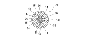
- FIG. 20 is a sectional view taken along line HH in FIG. 18.
- FIG. 21 is a front view of a sealing member used in the syringe outer cylinder shown in FIG. 18.
- FIG. 22 is a plan view of the seal member shown in FIG. 21.
- FIG. 23 is a bottom view of the seal member shown in FIG. 21.
- FIG. 24 is an enlarged cross-sectional explanatory view for explaining the state of the seal member inside the cap of the syringe outer cylinder of FIG. 17 before being attached to the outer cylinder.
- FIG. 25 is a bottom view of the cap used for the syringe outer cylinder shown in FIG. 18.
- FIG. 26 is a sectional view taken along the line JJ in FIG. 25.
- FIG. 27 is a sectional view taken along line KK in FIG. 25.
- FIG. 28 is a front view of another example of a sealing member used in the syringe outer cylinder of the present invention.
- FIG. 29 is a plan view of the seal member shown in FIG. 28.
- FIG. 30 is a bottom view of the seal member shown in FIG. 28.
- FIG. 31 is an enlarged cross-sectional explanatory view for explaining a state in which the seal member shown in FIG. 28 is attached to the cap shown in FIG. 25.
- FIG. 32 is an enlarged cross-sectional explanatory view for explaining a state in which the seal member shown in FIG. 28 is attached to the cap shown in FIG. 25 and is further attached to the outer cylinder.
- FIG. 33 is a front view of another example of a sealing member used in the syringe outer cylinder of the present invention.
- FIG. 34 is a plan view of the seal member shown in FIG. 33.
- FIG. 35 is a bottom view of the seal member shown in FIG. 33.
- FIG. 36 is a front view of another example of a sealing member used in the syringe outer cylinder of the present invention.
- FIG. 37 is a plan view of the seal member shown in FIG. 36.
- FIG. 38 is a bottom view of the seal member shown in FIG. 36.
- FIG. 39 is an enlarged cross-sectional explanatory view for explaining a state in which the seal member shown in FIG. 36 is attached to the cap shown in FIG. 25.
- FIG. 40 is an enlarged cross-sectional explanatory view for explaining a state in which the seal member shown in FIG. 36 is attached to the cap shown in FIG. 25 and is further attached to the outer cylinder.
- FIG. 41 is a front view of another example of a sealing member used in the syringe outer cylinder of the embodiment of the present invention.
- FIG. 42 is a plan view of the seal member shown in FIG. 41.
- FIG. 43 is a bottom view of the seal member shown in FIG. 41.
- FIG. 44 is a front view of another example of a sealing member used in the syringe outer cylinder according to the embodiment of the present invention.
- FIG. 45 is a plan view of the seal member shown in FIG. 44.
- FIG. 46 is a bottom view of the seal member shown in FIG. 44.
- FIG. 47 is a longitudinal sectional view of another example of a prefilled syringe using the syringe outer cylinder of the present invention.
- the syringe outer cylinder of the present invention includes an outer cylinder 2, 2a including a nozzle part 22 provided at the tip, a locking cylindrical part (4, 25) enclosing the nozzle part 22, and an outer cylinder 2, 2a.
- the cap 3 is a cylindrical member, and includes a sealing member storage part 31 that stores the elastic sealing member 6, a closing part 32 located above the sealing member storage part 31, and extending downward from the sealing member storage part 31.
- the nozzle part storage part 33 that stores the nozzle part 22, the cap side threaded part 33a formed on the outer surface of the nozzle part storage part 33, and the upper part of the seal member storage part 31 and the elastic part at least before attachment to the outer cylinder. It includes voids 13 and 14 formed between the upper surface periphery of the sealing member 6 or between the inner side of the sealing member accommodating portion 31 and the outer side of the elastic sealing member 6.
- the locking cylindrical portion 4 of the outer cylinder 2 includes a locking cylindrical portion side threaded portion 41a that can be screwed onto the cap side threaded portion 33a on the inner surface.
- the elastic seal member 6 is compressed by the inner surface of the cap 3 and the tip of the nozzle part 22, and is elastically deformed, and the bulges 62 and 64 formed by the elastic deformation fill the gap. It is located within the sections 13 and 14.
- the syringe of the present invention includes the above-mentioned syringe outer cylinders 1 and 1a, and a gasket 7 that is slidably housed in the syringe outer cylinder 1. It is what it is. Further, it may include a plunger 5 attached to the gasket 7.
- the prefilled syringe of the present invention includes the above-mentioned syringe outer cylinders 1, 1a, and a gasket slidably housed in the syringe outer cylinders 1, 1a. 7, and a medical liquid contained in an outer cylinder for a syringe. Further, it may include a plunger 5 attached to the gasket 7.
- the syringe outer cylinder 1 of the present invention includes an outer cylinder 2 and a cap 3 that is removably attached to the outer cylinder 2.
- the cap 3 is attached to the outer cylinder 2.
- the outer cylinder 2 includes an outer cylinder main body 20 and a lock adapter 4 rotatably attached to the outer cylinder main body 20 (specifically, the nozzle part 22). Equipped with The lock adapter 4 constitutes a locking cylindrical part that encloses the nozzle part 22.
- the outer cylinder main body 20 includes a hollow nozzle section 22 having an opening at its tip, a hollow main body section 21 , and a flange 23 provided at the base end of the hollow main body section 21 .
- the nozzle portion 22 can be connected to other medical instruments (for example, a syringe needle, a connector, a three-way stopcock).
- the lock adapter 4 has a locking cylindrical part side on its inner surface that can be screwed into a medical device (for example, a rib or a threaded part formed on a flange of a syringe needle, connector, three-way stopcock, etc.) connected to the nozzle part.
- a medical device for example, a rib or a threaded part formed on a flange of a syringe needle, connector, three-way stopcock, etc.
- a threaded portion 41a is provided.
- the flange 23 has an arcuate outer edge that is formed to protrude from the entire circumference of the base end of the hollow main body 21 in a direction perpendicular to the central axis of the outer cylinder main body.
- the hollow main body portion 21 of the outer cylinder main body 20 is formed into a cylindrical shape with a relatively small diameter, and is filled with a small amount (specifically, 0.5 ml to 2 ml) of a medicinal solution.
- the outer diameter of the hollow main body portion 21 is 6 to 12 mm. Note that the outer cylinder main body 20 is not limited to such a small diameter and accommodation capacity.
- the nozzle portion 22 has a smaller diameter than the outer diameter of the hollow main body portion 21, and the diameter decreases toward the tip.
- the nozzle portion 22 has a tip opening at its tip for discharging the chemical liquid and the like in the outer cylinder.
- the nozzle portion 22 is provided with a locking rib that can lock the lock adapter 4 at the base end (slightly closer to the tip than the tip of the hollow main body portion 21).
- the locking rib is an annular rib.
- Examples of materials for forming the outer cylinder body 20 and the lock adapter 4 include polypropylene, polyethylene, polystyrene, polyamide, polycarbonate, polyvinyl chloride, poly-(4-methylpentene-1), acrylic resin, and acrylonitrile-butadiene-styrene.
- Examples include various resins such as polymers, polyesters such as polyethylene terephthalate, cyclic polyolefin polymers, and cyclic olefin copolymers, but among them, polypropylene, cyclic polyolefin polymers, and cyclic olefin copolymers are easy to mold and have heat resistance.
- a resin is preferable.
- cyclic olefin polymers and cyclic olefin copolymers which are highly transparent so that the chemical liquid filled inside can be visually confirmed from the outside and have heat resistance that can withstand high-pressure steam sterilization, are used as the material for forming the outer cylinder body 20. Particularly preferred.
- the lock adapter 4 is a cylindrical member and is rotatably attached to the nozzle portion 22 of the outer cylinder body 20. Further, the lock adapter 4 is held at its lower part by a locking rib provided on the nozzle portion 22. Further, the lock adapter 4 includes an adapter-side threaded portion 41a that can be threadedly engaged with a cap-side threaded portion 33a of the cap 3, which will be described later. In this embodiment, the threaded portion 41a is formed by two spiral ribs.
- the locking cylindrical portion of the outer cylinder 2 is not limited to the lock adapter 4 as described above.
- the collar part 25 covers the nozzle part 22.
- the collar part 25 is formed in a cylindrical shape concentrically with the nozzle part 22 so as to surround the nozzle part 22. Further, the collar portion 25 has an open end, and the inner and outer diameters of the collar portion 25 are substantially the same from the base end to the front end. Further, the tip of the nozzle portion 22 protrudes from the tip opening of the collar portion 25 .
- a collar part side threaded part 26 is formed on the inner peripheral surface of the collar part 25 to be threadedly engaged with a cap side threaded part 33a formed in the nozzle part storage part 33 of the seal cap 3.
- the nozzle portion 22 of the outer cylinder 2a and the cap 3 are screwed together between the inner circumferential surface of the collar portion 25 and the outer circumferential surface of the nozzle storage portion.
- the threaded part 26 of the collar part 25 can be threaded with a threaded part on the side of a connector (for example, a needleless connector) provided on the injection needle hub, the blood circuit, and the drug solution administration line.
- the cap side screwing part 33a and the collar side screwing part 26 are both formed of spiral ribs and can be screwed together.
- the cap 3 is a cylindrical member, and includes a sealing member storage part 31 that stores the elastic sealing member 6, a closing part 32 located above the sealing member storage part 31, and extending downward from the sealing member storage part 31. It includes a nozzle part accommodating part 33 that accommodates the nozzle part 22 (specifically, the tip side part 22a of the nozzle part 22), and a cap side screwing part 33a formed on the outer surface of the nozzle part accommodating part 33. Further, in this embodiment, the cap 3 includes an upper cylindrical portion 34 extending upward from the closing portion 32. The upper cylindrical portion 34 is used as a grip portion when the cap 3 is detached from the outer cylinder 2.
- the cap-side threaded portion 33a of the cap 3 can be threaded with the adapter-side threaded portion 41a of the lock adapter 4 described above.
- the cap-side threaded portion 33a is formed by two spiral ribs.
- the material for forming the cap 3 include polypropylene, polyethylene, polystyrene, polyamide, polycarbonate, polyvinyl chloride, poly-(4-methylpentene-1), acrylic resin, acrylonitrile-butadiene-styrene copolymer, polyethylene terephthalate, etc.
- resins such as polypropylene and cyclic polyolefin are preferred because they are easy to mold and have heat resistance.
- the cap 3 is formed between the upper part (upper peripheral edge part) of the sealing member storage part 31 and the upper part of the elastic sealing member 6, at least before being attached to the outer cylinder 2 (when not attached). It is provided with a cavity 13.
- the syringe outer cylinder 1 of this embodiment as shown in FIG. and is deformed elastically.
- the bulging portion 62 of the elastic sealing member 6 formed by elastic deformation is positioned (enters) into the cavity 13, as shown in FIG.
- the elastic seal member 6 is made of an elastic material that can be elastically deformed by pressure between the inner surface 11 of the cap 3 and the tip 12 of the nozzle section 22, and that can liquid-tightly seal the tip opening of the nozzle section 22.
- an elastically deformable material such as natural rubber, isoprene rubber, butadiene rubber, fluororubber, synthetic rubber such as silicone rubber, thermoplastic elastomer such as olefin elastomer or styrene elastomer is used.
- the cap 3 is provided at the closing part 32, as shown in FIGS. It is equipped with Further, an annular portion 32b is provided at the upper peripheral edge of the central lower protrusion 32a.
- the outer and inner surfaces of the central lower protrusion 32a of the closing portion 32 are tapered toward the lower end of the central lower protrusion 32a, and the lower end of the central lower protrusion 32a is flat.
- the lower surface is shaped like this.
- the central lower protrusion 32a has a side surface whose diameter increases upward (toward the annular portion 32b) from the planar lower surface.
- An annular gap 13 having a tapered inner circumferential surface and whose inner circumferential surface increases in diameter upward is formed at the side of the central lower protrusion 32a.
- the elastic seal member 6 has a cylindrical shape, as shown in FIGS. 8 to 13. Specifically, as shown in FIGS. 11 to 13, the elastic seal member 6 of this embodiment is formed in a cylindrical shape, and has an annular rib 66 on the upper surface and a central portion ( 61, a tapered tip portion 68, a lower annular rib 67, and a lower flat portion 63 surrounded by the lower annular rib 67.
- the space between the upper part of the sealing member storage part 31 and the upper part of the elastic sealing member 6 is It has an annular cavity 13 formed therein.
- the annular cavity 13 has a substantially uniform outer diameter and an inner diameter between the annular side surface of the central lower protrusion 32a, the upper inner surface of the nozzle housing portion 33, and the upper portion of the elastic seal member 6. It is an annular cavity whose diameter gradually decreases toward the bottom and whose width gradually narrows toward the top. Further, the annular cavity 13 becomes thicker toward the circumferential direction.
- the planar lower surface of the central lower protrusion 32a of the closing portion 32 of the cap 3 closes the upper center of the elastic seal member 6.
- the (upper surface flat portion) 61 is pressed downward, and the lower surface flat portion 63 is pressed by the tip surface of the nozzle portion 22 of the outer cylinder 2.
- the elastic seal member 6 is compressed by the inner surface of the cap 3 and the tip of the nozzle portion 22, and is elastically deformed. Specifically, the upper center portion 61 of the elastic seal member 6 is pressed downward, and as shown in FIG. 3, the center portion becomes depressed and the upper portion bulges upward. In other words, The elastic seal member 6 deforms in the axial direction to form an annular bulge 62 extending in the axial direction, and the annular bulge 62 enters the annular cavity 13 .
- the bulging part (deformed part) of the elastic seal member 6 can enter the annular cavity 13, so that the elastic The generation of repulsive force due to the pinching pressure of the seal member 6 is suppressed. Therefore, separation of the cap 3 from the lock adapter 4 due to repulsion due to the clamping pressure of the elastic seal member 6 is prevented.
- the upper center portion 61 of the elastic seal member 6 is pressed in a circular manner by the flat lower surface of the central lower protrusion 32a of the closing portion 32 of the cap 3, and the lower surface flat portion of the elastic seal member 6 63 is pressed into a ring shape at the tip end surface of the nozzle portion 22 of the outer cylinder 2.
- the annular bulge 62 does not fill the entire annular void 13, but fills a part of the annular void 13, and in the case shown in FIG. The upper periphery remains. Furthermore, in this embodiment, as shown in FIG. is entering. As shown in FIG. 4, when the cap 3 is attached to the outer cylinder 2, the annular bulging portion 62 fills the entire annular gap 13, and the annular gap 13 substantially fills the annular gap 13. It may also disappear.
- the cap 3 of this embodiment includes a plurality of ribs 35 extending from the nozzle housing section 33 side toward the closing section 32.
- the elastic seal member 6 is held with its side surfaces abutting against the plurality of ribs 35.
- the elastic seal member 6 may be pressed by the plurality of ribs 35 to form a depression.
- the outer surface of the elastic seal member 6, except for the plurality of ribs 35 is It is separated from the inner surface of the body.
- the plurality of ribs 35 are provided at approximately equal angles to the central axis of the cap.
- the number of ribs 35 is preferably about 3 to 6, and in this embodiment, there are 4 ribs.
- the rib 35 extends from the upper end of the inner surface of the cap 3 toward the lower end, and terminates at a portion that does not reach the lower end.
- the end surface of the rib 35 may be an inclined surface that becomes lower toward the end.
- the elastic sealing member 6a may be provided with a plurality of rib recesses 44 on the side surface that can receive the tip end portions of the plurality of ribs 35.
- the cap 3a is not attached to the outer cylinder 2, as shown in FIG. It has become a thing.
- the syringe of the present invention includes the above-mentioned syringe outer cylinders 1, 1a, and a gasket 7 slidably housed in the syringe outer cylinders 1, 1a. It has a plunger 5 attached to a gasket 7. Furthermore, the prefilled syringes 10 and 10a of the present invention are slidably housed in the syringe outer cylinders 1 and 1a and the syringe outer cylinders 1 and 1a, as shown in FIGS. 15, 16, and 47.
- the syringe has a gasket 7 , a medical liquid stored in an outer cylinder for a syringe, and a plunger 5 attached to the gasket 7 .
- the illustrated gasket 7 includes a cylindrical main body 71, a closed tip 72, a distal end rib 74 formed on the outer surface of the cylindrical main body 71, a rear end rib 75, and an inner cavity formed on the inner surface. 73.
- This gasket includes ribs for threading on the inner surface of the inner cavity 73.
- the illustrated plunger 5 includes a main body part 51 having a flange part on the distal end side that can press the proximal end surface of the gasket 7, and a distal end part that protrudes forward from the main body part 51 and can enter into the inner cavity 73 of the gasket 7. 52.
- a plunger pressing portion 53 is provided at the base end of the main body portion 51 .
- the distal end portion 52 is a small-diameter cylindrical portion, and includes a screwing rib that can be screwed into a screwing rib provided on the inner surface of the inner cavity 73 of the gasket 7 .
- Known medical liquids can also be used. Specifically, a medical liquid, a flush liquid, a contrast medium, etc. are used as the medical liquid.
- the syringe outer cylinder 1b of the embodiment shown in FIGS. 17 to 27 will be described. Also in the syringe outer cylinder 1b of this embodiment, the same outer cylinder 2 as the syringe outer cylinder 1 described above is used. In this syringe outer cylinder 1b, a cap 3b and a seal member 6b are used.
- the sealing member 6b is a columnar body having a lower surface that comes into contact with an annular tip surface having an opening at the tip of the nozzle portion 22.
- the seal member 6b has a cylindrical shape extending with approximately the same outer diameter.
- the seal member 6b includes an upper flat portion and a lower flat portion. The lower flat portion contacts an annular tip surface having a tip opening of the nozzle portion 22 .
- the cap 3b includes a plurality of inner side protrusions 36 provided in the sealing member housing 31, and the gap 14 is formed between adjacent inner side protrusions 36.
- a plurality of side voids 14 are formed.
- the plurality of inner surface protrusions 36 are provided at approximately equal angles with respect to the central axis of the cap.
- the number of inner surface protrusions 36 is preferably about 3 to 6, and in this embodiment, it is 4.
- the cap 3b is a cylindrical member, and extends downward from the sealing member storage portion 31 that stores the elastic sealing member 6b, the closing portion 37 located above the sealing member storage portion 31, and the sealing member storage portion 31. It includes a nozzle part accommodating part 33 that accommodates the nozzle part 22 (specifically, the distal end part of the nozzle part 22), and a cap side screwing part 33a formed on the outer surface of the nozzle part accommodating part 33.
- the cap-side threaded portion 33a of the cap 3b can be threaded with the adapter-side threaded portion 41a of the lock adapter 4 described above.
- the cap-side threaded portion 33a is formed by two spiral ribs.
- the material for forming the cap 3b those described in connection with the cap 3 can be suitably used.
- the cap 3b includes a central upper protrusion 37a provided in the closing portion 37.
- An annular portion 37b is provided at the peripheral edge of the central upper protrusion 37a.
- the upper central protrusion 37a has an outer surface and an inner surface whose diameters decrease toward the upper end of the upper central protrusion 37a, and the upper end of the upper central protrusion 37a has a planar shape.
- an annular flat surface 11a is provided on the lower surface of the closing portion 37, and this annular flat surface 11a comes into contact with the upper part of the sealing member 6b, as shown in FIGS. 18 and 19. .
- a gap 17 is formed inside the central upper protrusion 37a.
- a plurality of side cavities 14 are provided.
- the plurality of side cavities 14 are isolated and do not communicate with each other.
- the plurality of inner side protrusions 36 of the cap 3b extend toward the center of the cap 3b and become wider toward the center.
- the tip surfaces of the plurality of inner surface protrusions 36 are provided with arcuate recesses extending in the axial direction. Therefore, as shown in FIG. 24, the distal end surfaces of the plurality of inner surface protrusions 36 face the side surfaces of the elastic seal member 6 and can make good contact therewith.
- the width of the plurality of side gaps 14 increases toward the circumferential edge, as shown in FIG. 24.
- an annular gap 16 is formed in the lower part of the seal member storage part 31, which is the lower part of the plurality of inner surface protrusions 36.
- the portion 16 communicates with the plurality of side cavities 14 .
- the plurality of inner surface protrusions 36 need only not come into contact with the tip end surface of the nozzle section 22 when attached to the outer cylinder; The lower end of may be close to the tip surface of the nozzle portion 22 .
- the cap 3b of this embodiment is attached to the outer cylinder 2, and the cap-side threaded portion 33a of the cap 3b and the adapter-side thread of the lock adapter 4 are connected.
- the annular flat surface 11a on the lower surface of the closing part 37 of the cap 3b closes the elastic seal member 6b.
- the upper part is pressed downward, and the lower surface of the elastic seal member 6b is pressed by the tip 12a of the nozzle part 22 of the outer cylinder 2.
- the side surface of the elastic seal member 6b abuts and is pressed against the tip end surface of the inner surface protrusion 36 at the contact portion 15.
- the elastic seal member 6b is compressed by the inner surface of the cap 3b and the tip of the nozzle portion 22, and is elastically deformed. Specifically, as shown in FIG. 20, the elastic seal member 6b partially bulges at the side, in other words, the elastic seal member 6b partially bulges in the circumferential direction (side direction, gap direction). A plurality of bulges 64 are formed that extend in the circumferential direction (in the side direction, in the direction of the gap), and each bulge 64 enters the corresponding gap 14 .
- the bulging part 64 (deformed part) of the elastic sealing member 6b can enter the cavity 14, so the elastic The generation of repulsive force due to the pinching pressure of the seal member 6b is suppressed. Therefore, separation of the cap 3b from the lock adapter 4 due to repulsion due to the clamping pressure of the elastic seal member 6b is prevented.
- the upper part of the elastic seal member 6b is pressed into a ring shape by the annular flat surface 11a which is the lower surface of the annular part 37b of the closing part 37, and the lower surface flat part of the elastic seal member 6b is pressed against the outer cylinder.
- the elastic seal member 6b is pressed in a ring shape by the tip end surface of the nozzle portion 22 of No. 2, and the side surface portion of the elastic seal member 6b is pressed by the tip end surface of the inner surface protrusion 36.
- each bulge 64 fills a part of the gap 14 without filling the entire gap 14 into which it has entered, and in the case shown in FIG. Only the side parts remain.
- the portion of the elastic seal member 6b located within the tip opening of the nozzle portion 22 bulges out slightly and enters the tip opening of the nozzle portion 22.
- the cap 3b may fill the entire gap 14 into which each bulging portion 64 enters when the cap 3b is attached to the outer cylinder 2, and the gap 14 may substantially disappear. good.
- the cap 3b of this embodiment includes a plurality of ribs 35 extending from the lower end of the plurality of inner surface protrusions 36 toward the lower end of the cap 3b. . Further, in the cap 3b of this embodiment, a plurality of ribs 35 are provided at approximately equal angles with respect to the central axis of the cap. The number of ribs 35 is preferably about 3 to 6, and in this embodiment, there are 4 ribs. Further, in this embodiment, the rib 35 extends from the upper end of the inner surface of the cap 3b toward the lower end, and terminates at a portion that does not reach the lower end.
- the elastic sealing member 6b is made of an elastic material that can be elastically deformed by pressure between the inner surface of the cap 3b and the tip of the nozzle portion 22, and can liquid-tightly seal the tip opening of the nozzle portion 22.
- the material for forming the elastic seal member 6b those described in connection with the elastic seal member 6 are preferably used.
- an elastic seal member 6c shown in FIGS. 28 to 30 may be used as the outer cylinder for a syringe of the present invention.
- the sealing member 6c is a columnar body having a lower surface that comes into contact with the annular tip surface having the tip opening of the nozzle portion 22, and has a cylindrical body portion 81 and a cylindrical body portion 81. It has an annular flange 82 provided at the bottom.
- This sealing member 6c as shown in FIGS. 31 and 32, can be used for the cap 3b shown in FIGS. 25 to 27 described above.
- the elastic seal member may have a recess 84 in the annular flange 82 corresponding to the rib 35 formed on the inner surface of the cap 3b, as in the elastic seal member 6d shown in FIGS. 33 to 35. good.
- an elastic seal member 6e shown in FIGS. 36 to 38 may be used as the outer cylinder for a syringe of the present invention.
- This sealing member 6e as shown in FIGS. 39 and 40, can be used for the cap 3b shown in FIGS. 25 to 27 described above.
- the sealing member 6e of this embodiment is a columnar body having a lower surface that comes into contact with the annular tip surface having the tip opening of the nozzle portion 22, and has a columnar body portion 81a and a columnar body portion 81a.
- a plurality of recesses 85 are provided on the side of the main body portion 81a.
- the cap 3b includes a plurality of inner surface protrusions 36, and the voids 14 are a plurality of side voids formed between adjacent inner surface protrusions 36.
- the elastic seal member 6e of this embodiment includes a plurality of protrusion recesses 85 on the side of the cylindrical main body 81a, which can receive the tip end portions of the side protrusions 36.
- the protrusion recess 85 extends from the upper surface of the elastic sealing member (cylindrical main body 81a) toward the lower surface and does not reach the lower surface. It has a bottom part (the bottom part of the protruding part recess 85). Therefore, when the cap 3b is attached to the outer cylinder 2, the bottom surface of the protrusion recess 85 (the bottom of the protrusion recess 85) is located between the lower surface of the plurality of protrusion recesses 85 and the tip surface of the nozzle part 22. and is squeezed.
- the tip side portion of the side protrusion 36 of the cap is housed in the protrusion recess 85. Further, the portion of the sealing member 6e located between the protrusion recesses 85 enters between the side protrusions 36 that are part of the cavity 14. Also in this embodiment, when the cap 3b is attached to the outer cylinder 2, the side portions of the elastic seal member 6e partially swell out, as shown in FIG. , a plurality of bulges 64 are formed that are partially deformed in the circumferential direction and extend in the circumferential direction, and each bulge 64 enters the corresponding void 14 .
- the seal member 6e described above may include an annular flange 82 provided at the lower part of the cylindrical main body portion 81b, like the seal member 6f shown in FIGS. 41 to 43.
- the seal member 6e described above may have a recess 84 in the annular flange 82 corresponding to the rib 35 formed on the inner surface of the cap 3b, as in the elastic seal member 6g shown in FIGS. 44 to 46. good.
- the outer barrel for a syringe of the present invention includes an outer barrel including a nozzle portion provided at the tip, a locking cylindrical portion that encloses the nozzle portion, a cap that is removably attached to the outer barrel, and a cap that is detachably attached to the outer barrel, and a syringe that is housed in the cap.
- a syringe outer cylinder including an elastic seal member for sealing a tip opening of a nozzle part.
- the cap is a cylindrical member, and includes a sealing member storage part that stores an elastic sealing member, a closing part located above the sealing member storage part, and a nozzle part that extends downward from the sealing member storage part.
- the locking cylindrical part of the outer cylinder has a locking cylindrical part on the inner surface that can be screwed into the cap side screwing part.
- the syringe outer cylinder of the present invention is as follows. (1) An outer cylinder including a nozzle part provided at the tip, a locking cylindrical part enclosing the nozzle part, a cap that is removably attached to the outer cylinder, and a cap that is housed in the cap and that locks the nozzle.
- An outer cylinder for a syringe comprising an elastic sealing member for sealing a distal end opening of the syringe,
- the cap is a cylindrical member, and includes a sealing member storage part that stores the elastic sealing member, a closing part located above the sealing member storage part, and a nozzle part that extends downward from the sealing member storage part.
- the locking cylindrical part of the outer cylinder includes a locking cylindrical part side threaded part on an inner surface that can be threadedly engaged with the cap side threaded part,
- This syringe outer cylinder includes an outer cylinder including a nozzle part provided at the tip, a locking cylindrical part that encloses the nozzle part, a cap that is detachable from the outer cylinder, and a nozzle that is housed in the cap.
- This is an outer cylinder for a syringe, and includes an elastic sealing member for sealing a distal end opening of the syringe.
- the cap is a cylindrical member, and includes a sealing member storage part that stores an elastic sealing member, a closing part located above the sealing member storage part, and a nozzle part that extends downward from the sealing member storage part.
- the locking cylindrical part of the outer cylinder has a locking cylindrical part on the inner surface that can be screwed into the cap side screwing part.
- the above embodiments may be as follows. (2) The syringe outer cylinder according to (1) above, wherein the locking cylindrical part is a lock adapter rotatably attached to the nozzle part. (3) The syringe outer cylinder according to (1) above, wherein the locking cylindrical part is a collar part integrally formed with the outer cylinder. (4) The syringe outer cylinder according to any one of (1) to (3) above, wherein the elastic seal member is cylindrical. (5) The syringe outer cylinder according to any one of (1) to (3) above, wherein the elastic sealing member includes a cylindrical main body and an annular flange provided at a lower part of the cylindrical main body. .
- the cap includes a plurality of ribs extending from the nozzle storage section side toward the closing section, and the elastic seal member has a side surface pressed by the plurality of ribs.
- the outer cylinder for a syringe according to any one of 5).
- the cap includes a plurality of ribs extending from the nozzle storage section toward the closing section, and the elastic seal member includes a plurality of rib recesses capable of receiving tip end portions of the ribs.
- the outer cylinder for a syringe according to any one of (1) to (6) above.
- the outer cylinder for a syringe according to any one of (1) to (7) above, wherein the elastic seal member is a columnar body having a lower surface that comes into contact with an annular tip surface having a tip opening of the nozzle portion.
- the closing portion includes a central lower protrusion having a planar lower surface, and the elastic seal member has a central upper surface pressed downward by the planar lower surface of the central lower protruding portion.
- the above-mentioned structure in which the cavity is an annular cavity formed between a side surface of the central lower protrusion of the closing part, an upper inner surface of the cap, and a peripheral edge of the upper surface of the elastic sealing member.
- the outer cylinder for a syringe according to (9).
- the cavity is an annular cavity formed between a side surface of the central lower protrusion of the closing part, an upper inner surface of the cap, and a peripheral edge of the upper surface of the elastic sealing member, (9) or (10) above, wherein when the cap is attached to the outer cylinder, the upper annular bulge extending upward in the axial direction formed by elastic deformation of the elastic sealing member enters the gap.
- Outer cylinder for syringe Outer cylinder for syringe.
- the cap includes a plurality of inner side protrusions provided in the sealing member housing, and the voids are a plurality of side gaps formed between adjacent inner side protrusions.
- the outer cylinder for a syringe according to any one of (1) to (8) above.
- the cap includes a plurality of inner surface protrusions provided in the sealing member housing, and the voids are a plurality of side voids formed between adjacent inner surface protrusions. (1) to (8) above, wherein a plurality of side bulges formed by elastic deformation of the elastic sealing member enter the side gap when the cap is attached to the outer cylinder. ) or (12).
- the syringe of the present invention is as follows. (14) A syringe comprising the syringe outer cylinder according to any one of (1) to (13) above, and a gasket slidably housed within the syringe outer cylinder.
- the prefilled syringe of the present invention is as follows. (15) The syringe outer cylinder according to any one of (1) to (13) above, in which the cap is attached to the outer cylinder, and the syringe outer cylinder is slidably housed within the syringe outer cylinder. A prefilled syringe comprising a gasket and a medical liquid stored in the syringe outer cylinder.
Landscapes
- Health & Medical Sciences (AREA)
- Vascular Medicine (AREA)
- Engineering & Computer Science (AREA)
- Anesthesiology (AREA)
- Biomedical Technology (AREA)
- Heart & Thoracic Surgery (AREA)
- Hematology (AREA)
- Life Sciences & Earth Sciences (AREA)
- Animal Behavior & Ethology (AREA)
- General Health & Medical Sciences (AREA)
- Public Health (AREA)
- Veterinary Medicine (AREA)
- Infusion, Injection, And Reservoir Apparatuses (AREA)
Abstract
Ce cylindre externe 1 pour une seringue comprend : un cylindre externe 2 comprenant une partie de buse 22 et une partie cylindrique de verrouillage 4 ; un capuchon 3 fixé de manière amovible au cylindre externe ; et un élément d'étanchéité élastique 6 qui est logé dans le capuchon. Le capuchon comprend : une partie de réception d'élément d'étanchéité 31 ; une partie fermée 32 qui est positionnée au-dessus de la partie de réception d'élément d'étanchéité ; une partie de mise en prise filetée côté capuchon 33a ; une partie de réception de buse 33 ; et une cavité 13 qui est formée entre la partie supérieure de la partie de réception d'élément d'étanchéité et le bord périphérique supérieur de l'élément d'étanchéité élastique lorsque le capuchon n'est pas fixé au cylindre externe. La partie cylindrique de verrouillage 4 comprend une partie de mise en prise filetée côté partie cylindrique de verrouillage 41a. Lorsque le capuchon est fixé au cylindre externe, un renflement 62 sur l'élément d'étanchéité élastique, qui est formé par la pression de serrage entre la surface interne du capuchon et la pointe de la buse, est positionné à l'intérieur de la cavité 13.
Applications Claiming Priority (2)
| Application Number | Priority Date | Filing Date | Title |
|---|---|---|---|
| JP2022-044681 | 2022-03-18 | ||
| JP2022044681 | 2022-03-18 |
Publications (1)
| Publication Number | Publication Date |
|---|---|
| WO2023176064A1 true WO2023176064A1 (fr) | 2023-09-21 |
Family
ID=88023185
Family Applications (1)
| Application Number | Title | Priority Date | Filing Date |
|---|---|---|---|
| PCT/JP2022/045543 WO2023176064A1 (fr) | 2022-03-18 | 2022-12-09 | Cylindre externe pour seringue, seringue et seringue pré-remplie |
Country Status (1)
| Country | Link |
|---|---|
| WO (1) | WO2023176064A1 (fr) |
Citations (4)
| Publication number | Priority date | Publication date | Assignee | Title |
|---|---|---|---|---|
| JP2009240684A (ja) * | 2008-03-31 | 2009-10-22 | Terumo Corp | キャップおよびプレフィルドシリンジの製造方法 |
| WO2014102987A1 (fr) * | 2012-12-27 | 2014-07-03 | テルモ株式会社 | Cylindre extérieur de seringue pré-remplie et son conditionnement |
| JP2016537064A (ja) * | 2013-10-15 | 2016-12-01 | ベクトン ディキンソン フランス | 注射システムを閉鎖するための先端部キャップアセンブリ |
| JP2017196499A (ja) * | 2012-03-28 | 2017-11-02 | テルモ株式会社 | シリンジ |
-
2022
- 2022-12-09 WO PCT/JP2022/045543 patent/WO2023176064A1/fr unknown
Patent Citations (4)
| Publication number | Priority date | Publication date | Assignee | Title |
|---|---|---|---|---|
| JP2009240684A (ja) * | 2008-03-31 | 2009-10-22 | Terumo Corp | キャップおよびプレフィルドシリンジの製造方法 |
| JP2017196499A (ja) * | 2012-03-28 | 2017-11-02 | テルモ株式会社 | シリンジ |
| WO2014102987A1 (fr) * | 2012-12-27 | 2014-07-03 | テルモ株式会社 | Cylindre extérieur de seringue pré-remplie et son conditionnement |
| JP2016537064A (ja) * | 2013-10-15 | 2016-12-01 | ベクトン ディキンソン フランス | 注射システムを閉鎖するための先端部キャップアセンブリ |
Similar Documents
| Publication | Publication Date | Title |
|---|---|---|
| US8460250B2 (en) | Medical container | |
| EP2554204B1 (fr) | Seringue préremplie | |
| US10406289B2 (en) | Drug injection syringe | |
| JP5283417B2 (ja) | キャップおよびプレフィルドシリンジの製造方法 | |
| WO2001097885A1 (fr) | Seringue | |
| JP2002272843A (ja) | シリンジ | |
| JP4156791B2 (ja) | プレフィルドシリンジ用注射器およびプレフィルドシリンジ | |
| JP5896669B2 (ja) | シリンジ用プランジャー、シリンジおよびプレフィルドシリンジ | |
| JP2015213776A (ja) | 使用上の安全性を高めた使い捨て注射器のシリンダ−ピストン・ユニット | |
| WO2023176064A1 (fr) | Cylindre externe pour seringue, seringue et seringue pré-remplie | |
| WO2018173925A1 (fr) | Seringue femelle et kit de seringue | |
| JP7413355B2 (ja) | 接続構造及び薬液投与器具 | |
| JPWO2014045405A1 (ja) | 薬剤投与器具 | |
| JP4156790B2 (ja) | プレフィルドシリンジ用注射器およびプレフィルドシリンジ | |
| JP5714268B2 (ja) | プレフィルドシリンジ | |
| JP4133124B2 (ja) | シリンジ用ガスケット、ガスケット付プランジャー、シリンジ及びプレフィルドシリンジ | |
| JP4299509B2 (ja) | プレフィルドシリンジ用注射器およびプレフィルドシリンジ | |
| JP4449401B2 (ja) | プレフィルドシリンジ | |
| JP5824223B2 (ja) | 2連式プレフィルドシリンジ | |
| JP4381614B2 (ja) | プレフィルドシリンジの製造方法 | |
| JP5411556B2 (ja) | プレフィルドシリンジ用注射器およびプレフィルドシリンジ | |
| JP2004121344A (ja) | シリンジ用ガスケット、ガスケット付プランジャー、シリンジ及びプレフィルドシリンジ | |
| CN209848027U (zh) | 无针注射器的储药管的注射头组件、储药管和无针注射器 | |
| JP5489548B2 (ja) | プレフィルドシリンジ | |
| JP7322061B2 (ja) | シリンジ用キャップ、シリンジ組立体及びプレフィルドシリンジ |
Legal Events
| Date | Code | Title | Description |
|---|---|---|---|
| 121 | Ep: the epo has been informed by wipo that ep was designated in this application |
Ref document number: 22932327 Country of ref document: EP Kind code of ref document: A1 |