WO2023175834A1 - 電解水生成装置および電解水生成装置の制御方法 - Google Patents
電解水生成装置および電解水生成装置の制御方法 Download PDFInfo
- Publication number
- WO2023175834A1 WO2023175834A1 PCT/JP2022/012289 JP2022012289W WO2023175834A1 WO 2023175834 A1 WO2023175834 A1 WO 2023175834A1 JP 2022012289 W JP2022012289 W JP 2022012289W WO 2023175834 A1 WO2023175834 A1 WO 2023175834A1
- Authority
- WO
- WIPO (PCT)
- Prior art keywords
- water
- cathode
- value
- anode
- electrolyzed water
- Prior art date
- Legal status (The legal status is an assumption and is not a legal conclusion. Google has not performed a legal analysis and makes no representation as to the accuracy of the status listed.)
- Ceased
Links
Images


Classifications
-
- C—CHEMISTRY; METALLURGY
- C02—TREATMENT OF WATER, WASTE WATER, SEWAGE, OR SLUDGE
- C02F—TREATMENT OF WATER, WASTE WATER, SEWAGE, OR SLUDGE
- C02F1/00—Treatment of water, waste water, or sewage
- C02F1/46—Treatment of water, waste water, or sewage by electrochemical methods
- C02F1/461—Treatment of water, waste water, or sewage by electrochemical methods by electrolysis
-
- C—CHEMISTRY; METALLURGY
- C02—TREATMENT OF WATER, WASTE WATER, SEWAGE, OR SLUDGE
- C02F—TREATMENT OF WATER, WASTE WATER, SEWAGE, OR SLUDGE
- C02F1/00—Treatment of water, waste water, or sewage
- C02F1/46—Treatment of water, waste water, or sewage by electrochemical methods
- C02F1/461—Treatment of water, waste water, or sewage by electrochemical methods by electrolysis
- C02F1/46104—Devices therefor; Their operating or servicing
- C02F1/4618—Devices therefor; Their operating or servicing for producing "ionised" acidic or basic water
-
- C—CHEMISTRY; METALLURGY
- C02—TREATMENT OF WATER, WASTE WATER, SEWAGE, OR SLUDGE
- C02F—TREATMENT OF WATER, WASTE WATER, SEWAGE, OR SLUDGE
- C02F1/00—Treatment of water, waste water, or sewage
- C02F1/66—Treatment of water, waste water, or sewage by neutralisation; pH adjustment
-
- C—CHEMISTRY; METALLURGY
- C02—TREATMENT OF WATER, WASTE WATER, SEWAGE, OR SLUDGE
- C02F—TREATMENT OF WATER, WASTE WATER, SEWAGE, OR SLUDGE
- C02F1/00—Treatment of water, waste water, or sewage
- C02F1/46—Treatment of water, waste water, or sewage by electrochemical methods
- C02F1/461—Treatment of water, waste water, or sewage by electrochemical methods by electrolysis
- C02F1/46104—Devices therefor; Their operating or servicing
- C02F1/4618—Devices therefor; Their operating or servicing for producing "ionised" acidic or basic water
- C02F2001/4619—Devices therefor; Their operating or servicing for producing "ionised" acidic or basic water only cathodic or alkaline water, e.g. for reducing
-
- C—CHEMISTRY; METALLURGY
- C02—TREATMENT OF WATER, WASTE WATER, SEWAGE, OR SLUDGE
- C02F—TREATMENT OF WATER, WASTE WATER, SEWAGE, OR SLUDGE
- C02F2201/00—Apparatus for treatment of water, waste water or sewage
- C02F2201/46—Apparatus for electrochemical processes
- C02F2201/461—Electrolysis apparatus
- C02F2201/46105—Details relating to the electrolytic devices
- C02F2201/46115—Electrolytic cell with membranes or diaphragms
-
- C—CHEMISTRY; METALLURGY
- C02—TREATMENT OF WATER, WASTE WATER, SEWAGE, OR SLUDGE
- C02F—TREATMENT OF WATER, WASTE WATER, SEWAGE, OR SLUDGE
- C02F2201/00—Apparatus for treatment of water, waste water or sewage
- C02F2201/46—Apparatus for electrochemical processes
- C02F2201/461—Electrolysis apparatus
- C02F2201/46105—Details relating to the electrolytic devices
- C02F2201/4612—Controlling or monitoring
-
- C—CHEMISTRY; METALLURGY
- C02—TREATMENT OF WATER, WASTE WATER, SEWAGE, OR SLUDGE
- C02F—TREATMENT OF WATER, WASTE WATER, SEWAGE, OR SLUDGE
- C02F2201/00—Apparatus for treatment of water, waste water or sewage
- C02F2201/46—Apparatus for electrochemical processes
- C02F2201/461—Electrolysis apparatus
- C02F2201/46105—Details relating to the electrolytic devices
- C02F2201/4612—Controlling or monitoring
- C02F2201/46125—Electrical variables
- C02F2201/4614—Current
-
- C—CHEMISTRY; METALLURGY
- C02—TREATMENT OF WATER, WASTE WATER, SEWAGE, OR SLUDGE
- C02F—TREATMENT OF WATER, WASTE WATER, SEWAGE, OR SLUDGE
- C02F2201/00—Apparatus for treatment of water, waste water or sewage
- C02F2201/46—Apparatus for electrochemical processes
- C02F2201/461—Electrolysis apparatus
- C02F2201/46105—Details relating to the electrolytic devices
- C02F2201/4612—Controlling or monitoring
- C02F2201/46145—Fluid flow
-
- C—CHEMISTRY; METALLURGY
- C02—TREATMENT OF WATER, WASTE WATER, SEWAGE, OR SLUDGE
- C02F—TREATMENT OF WATER, WASTE WATER, SEWAGE, OR SLUDGE
- C02F2201/00—Apparatus for treatment of water, waste water or sewage
- C02F2201/46—Apparatus for electrochemical processes
- C02F2201/461—Electrolysis apparatus
- C02F2201/46105—Details relating to the electrolytic devices
- C02F2201/4616—Power supply
- C02F2201/4617—DC only
-
- C—CHEMISTRY; METALLURGY
- C02—TREATMENT OF WATER, WASTE WATER, SEWAGE, OR SLUDGE
- C02F—TREATMENT OF WATER, WASTE WATER, SEWAGE, OR SLUDGE
- C02F2209/00—Controlling or monitoring parameters in water treatment
- C02F2209/05—Conductivity or salinity
- C02F2209/055—Hardness
-
- C—CHEMISTRY; METALLURGY
- C02—TREATMENT OF WATER, WASTE WATER, SEWAGE, OR SLUDGE
- C02F—TREATMENT OF WATER, WASTE WATER, SEWAGE, OR SLUDGE
- C02F2209/00—Controlling or monitoring parameters in water treatment
- C02F2209/06—Controlling or monitoring parameters in water treatment pH
-
- C—CHEMISTRY; METALLURGY
- C02—TREATMENT OF WATER, WASTE WATER, SEWAGE, OR SLUDGE
- C02F—TREATMENT OF WATER, WASTE WATER, SEWAGE, OR SLUDGE
- C02F2209/00—Controlling or monitoring parameters in water treatment
- C02F2209/07—Alkalinity
Definitions
- the present disclosure relates to an electrolyzed water generating device and a method of controlling the electrolyzed water generating device.
- a conventional electrolyzed water generating device is a device that is easily connected to a water supply or a well through a water pipe, and supplies cathode water (alkaline ionized water or reduced water) or anode water (acidic water) through electrolysis.
- Water from taps or wells may be purified using a water filter such as activated carbon before being supplied to the device.
- a water filter may also be built into the device.
- the water supplied to the electrolyzed water generator will be referred to as raw water.
- the quality of raw water varies considerably depending on the region and country.
- free carbon dioxide refers to carbon dioxide gas dissolved in water, and is abundant in groundwater. While raw water in Japan is soft water, raw water in the United States and Europe is often hard water. Therefore, the types and amounts of ions generated during the electrolysis of raw water vary considerably depending on the region and country. In particular, it is known that free carbonate changes into various ionic forms depending on the pH, and that a buffering effect is exerted depending on the abundance of each ionic form. Therefore, it is required to control the electrolyzed water generating device according to the quality of raw water.
- the JIS standards state that ⁇ those who are drinking it for the first time should drink it from a small amount in a range close to neutral'' and ⁇ If drinking alkaline electrolyzed water, When used for food, the appropriate pH value is 9.5, and if it has a pH of 10 or higher, it is not drinkable and should not be consumed directly.'' For this reason, it is required to inform users of the pH of electrolyzed water.
- the selection button displays weak alkaline water (pH 8.5), medium alkaline water (pH 9.0), and strong alkaline water (pH 9.5), or weakly reduced water. , medium reduced water, and strong reduced water are only displayed, and the pH of these electrolyzed waters is not detected. Therefore, there is a problem that the pH is not detected or displayed at the time of drinking, and the selected pH is not guaranteed in some cases.
- the electrolyzed water maker disclosed in Patent Document 1 calculates pH from a theoretical formula and performs control accordingly.
- this theoretical formula is defined for theoretical water (or water that does not contain impurities), and even if it is applicable to barely pure water, it cannot be applied to ordinary tap water, well water, or electrolyzed water. It cannot be applied to raw water or electrolyzed water in equipment.
- this theoretical formula is applied to an actual device, the antilogarithm can take a negative value, so there remains a doubt as to whether it will function properly.
- the continuous ion-rich water generation method disclosed in Patent Document 2 determines the required power according to the amount of bicarbonate ions without providing a pH meter.
- the relationship between electrical conductivity and bicarbonate ion concentration in Patent Document 2 is a relationship in tap water, not a relationship during electrolysis.
- the quality of tap water varies considerably depending on region and country. Therefore, the method of Patent Document 2 seems to be unreliable for determining the amount of bicarbonate ions during electrolysis.
- bicarbonate ions are inherently unstable and easily combine with minerals in water, so they are not suitable as an indicator of pH.
- one of the purposes of the present disclosure is to detect the pH of electrolyzed water as necessary.
- the electrolyzed water generating device has at least a pair of anode and a cathode, and an anode chamber and a cathode chamber separated from each other by a diaphragm, the anode chamber housing the anode, and the cathode chamber housing the cathode. It includes an electrolytic cell, a power supply section for passing a current between the anode and the cathode, and a control section that controls the power supply section, and the control section electrically controls the raw water introduced into the electrolytic cell.
- An electrolyzed water generating device that controls the power supply unit to decompose and generate cathode water in the cathode chamber and to generate anode water in the anode chamber, the control unit controlling the voltage applied during the electrolysis.
- the current is i [A] and the flow rate of the raw water in the cathode chamber during the electrolysis is f [L/min]
- the value is Alog (i/f) + B (where A and B are constants). Based on this, the pH of the cathode water is detected.
- the control method includes an electrolytic cell having at least a pair of anode and a cathode, an anode chamber and a cathode chamber separated from each other by a diaphragm, the anode being housed in the anode chamber, and the cathode being housed in the cathode chamber. and a power supply section for passing a current between the anode and the cathode, the method comprising: (i) electrolyzing the raw water introduced into the electrolytic cell to generate the electrolyzed water.
- the pH of electrolyzed water can be detected as needed.
- FIG. 1 is a front view schematically showing the electrolyzed water generating device of Embodiment 1.
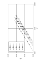
- FIG. 2 is a graph showing the results of a measurement test in Embodiment 1.
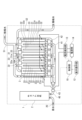
- FIG. 2 is a front view schematically showing an electrolyzed water generating device of Embodiment 2.
- FIG. It is a flow chart of a control method of an electrolyzed water generation device.
- Embodiments of the electrolyzed water generating device and the method of controlling the electrolyzed water generating device according to the present disclosure will be described below by giving examples. However, the present disclosure is not limited to the examples described below. In the following description, specific numerical values and materials may be illustrated, but other numerical values and materials may be applied as long as the effects of the present disclosure can be obtained.
- the electrolyzed water generation device includes at least a pair of anode and cathode, an electrolytic cell, a power supply section, and a control section.
- At least one pair of anode and cathode may each be composed of an electrode plate.
- the anode and the cathode may be provided in one pair or in plural pairs.
- the electrolytic cell has an anode chamber and a cathode chamber separated from each other by a diaphragm.
- the diaphragm may be any material as long as it has ion permeability, and a porous membrane or an ion exchange membrane may be used.
- An anode is housed in the anode chamber.
- a cathode is housed in the cathode chamber.
- the material and structure of the anode and cathode are not particularly limited, and known materials such as metals and carbon materials may be used.
- the number of anode chambers may be the same as or different from the number of anodes.
- the number of cathode chambers may be the same as the number of cathodes, or may be different. If multiple anodes are present, each of the multiple anode chambers may house one or more anodes. If multiple cathodes are present, one or more cathodes may be housed in each of the multiple cathode chambers.
- the power supply section is an element for passing current between the anode and the cathode.
- the power supply unit may, for example, apply a DC voltage between the anode and the cathode to cause a current to flow between the anode and the cathode.
- the control unit is an element for controlling the power supply unit.
- the control unit controls the power supply unit to electrolyze raw water introduced into the electrolytic cell to generate cathode water in the cathode chamber and to generate anode water in the anode chamber.
- the control unit may include an arithmetic device and a storage device storing a program executable by the arithmetic device.
- the program stored in the storage device may be a program for causing a computer to execute a method for controlling an electrolyzed water generating device according to the present disclosure.
- the control unit Based on the value of Alog (i/f) + B, the control unit sets the applied current during electrolysis to i [A] and the flow rate of raw water in the cathode chamber during electrolysis to f [L/min], Detects the pH of cathode water.
- a and B are each constants, and may be determined analytically and/or experimentally, for example, based on the specific configuration of the electrolyzed water generating device or the quality of raw water.
- the inventor of the present application has discovered that by using the value of Alog(i/f)+B, the pH of the cathode water generated by the electrolyzed water generation device can be directly determined from the phenomenon during electrolysis, and that the desired pH of the cathode water can be determined. We have discovered that it is possible to detect at the appropriate timing as needed. This will be described in detail later.
- the electrolyzed water generating device may automatically or the operator of the device may manually increase, decrease, or intermittent the applied current and/or the flow rate of raw water for electrolysis. Note that when such an operation is automatically performed by the electrolyzed water generating device, there is an advantage that the operation can be performed only by elements within the device such as a power supply unit.
- the value of the constant A may be set as a value specific to the electrolyzed water generation device based on the measured value of the pH of the cathode water and the value of i/f.
- the inventor of the present application found that there is a proportional correlation between the measured value of pH of cathode water and the value of log(i/f). It is the constant A that defines this proportional relationship, and the inventors have also discovered that the constant A has a unique value for each electrolyzed water generating device.
- the pH of the cathode water for setting the constant A may be actually measured using a pH meter or a pH sensor, for example.
- the constant A may be set, for example, by the manufacturer of the electrolyzed water generating device before shipping the electrolyzed water generating device.
- the constant A is a value unique to each device regardless of the quality of the raw water, it can be set by the manufacturer at any location using any raw water.
- the value of i may be detected by a current sensor commonly included in electrolyzed water generating devices.
- the value of f may be detected by a flow rate sensor commonly included in electrolyzed water generating devices.
- the value of the constant B may be set as a value corresponding to the quality of the raw water based on at least the measured value of the pH of the cathode water.
- the inventors of the present invention have found that it is effective to add a constant B to Alog(i/f) in order to detect the pH of cathode water while taking into account the quality of raw water.
- the value of constant B can be determined by, for example, determining the value of constant A as necessary, introducing raw water into the electrolyzed water generator, and actually measuring the pH of the cathode water obtained by electrolyzing it. Can be set based on value.
- the constant B may be set using raw water at the site where the electrolyzed water generating apparatus is actually used, before the start of normal use of the electrolyzed water generating apparatus. Furthermore, in cases where there is a possibility that the quality of raw water may change over time, the constant B may be set and reset at an appropriate timing.
- the electrolyzed water generating device may further include a notification unit that reports information regarding the detected pH of the cathode water (hereinafter also referred to as detected pH).
- the notification unit may notify the user of the information visually or aurally.
- the notification unit may include a display that displays the detected pH value, a lamp that changes color depending on the detected pH value, or a speaker that audibly conveys the detected pH value.
- the information regarding pH may include the values of constant A and constant B.
- a method for controlling an electrolyzed water generating device is a method for controlling an electrolyzed water generating device including at least one pair of an anode and a cathode, an electrolytic cell, and a power supply unit.
- the configurations of at least one pair of anode and cathode, the electrolytic cell, and the power supply section may be the same as those described above.
- the control method includes a step (i) and a step (ii).
- step (i) the power supply section is controlled to electrolyze the raw water introduced into the electrolytic cell to generate cathode water in the cathode chamber and to generate anode water in the anode chamber. This allows the user to utilize cathode water or anode water as needed.
- step (ii) the applied current during electrolysis is i [A], and the flow rate of raw water in the cathode chamber during electrolysis is f [L/min], and based on the value of Alog (i/f) + B.
- a and B are each constants, and may be determined analytically and/or experimentally, for example, based on the specific configuration of the electrolyzed water generating device or the quality of raw water.
- the electrolyzed water generating device may automatically or the operator of the device may manually increase, decrease, or intermittent the applied current and/or the flow rate of raw water for electrolysis.
- “using the value of Alog(i/f)+B” broadly includes cases where the value of Alog(i/f)+B at one or more arbitrary timings is used as an index.
- the value of Alog(i/f)+B may be used as is, or may be converted using various functions, or the value of Alog(i/f)+B at multiple timings may be processed (for example, integrated or averaged). It may also be used as
- the control method for the electrolyzed water generator is to set a constant A as a value specific to the electrolyzed water generator based on the measured value of pH of the cathode water and the value of i/f.
- the method may further include a step of setting a value.
- the pH of the cathode water may be measured using, for example, a pH meter or a pH sensor.
- the value of i may be detected by a current sensor commonly included in electrolyzed water generating devices.
- the value of f may be detected by a flow sensor commonly provided in electrolyzed water generating devices.
- the method for controlling an electrolyzed water generator further comprises (iv) before step (ii), setting a constant B as a value corresponding to the quality of the raw water based on at least the measured pH value of the cathode water. It's okay.
- the value of constant B can be determined by, for example, determining the value of constant A as necessary, introducing raw water into the electrolyzed water generator, and actually measuring the pH of the cathode water obtained by electrolyzing it. Can be set based on value.
- the method for controlling the electrolyzed water generating device may further include the step of (v) reporting information regarding the detected pH of the cathode water.
- the information may be visually or aurally reported to the user.
- the information is announced by a display that displays the detected pH value, by a lamp that changes color depending on the detected pH value, or by a speaker that audibly conveys the detected pH value. Good too.
- the pH of electrolyzed water (cathode water) can be detected as necessary. Furthermore, according to the present disclosure, effects (1) to (3) listed below can be obtained. (1) By using (i/f), a parameter that has not been shown until now, water with a desired pH can be obtained regardless of cultural lifestyles, both domestically and internationally, without depending on the quality of raw water or the form of use. Optimum control can be achieved. (2) In order to obtain the values of current and flow rate during electrolysis, the flow rate sensor and current sensor that are conventionally installed in electrolyzed water generation equipment are used, so there is no need to introduce additional devices. It is possible to detect and control the pH of electrolyzed water at the appropriate timing.
- i is the electrolysis current, that is, the applied current [A]
- f is the flow rate of raw water in the cathode chamber during electrolysis [L/min]
- a and B are each constants. Note that the base of log(i/f) is 10, and all logarithms in this specification are common logarithms.
- the constant A in equation (1) is determined by the structure, shape, and material of the electrolytic cell, and the structure, shape, and material of the diaphragm.
- the constant B in equation (1) is approximately determined by the quality of raw water.
- water such as raw water, well water, groundwater, freshwater from a river or a lake in the present disclosure contains anions such as Cl - , NO - , SO 4 2- , HCO 3 - , CO 3 2- , Cations such as Na + , K + , Ca 2+ , Mg 2+ are included.
- the types and amounts of these ingredients vary depending on the region and country. The details of the contributions made by these ions will have to wait for some research, but it can be considered that the constant B is the total contribution.
- an example of an electrolyzed water generating device and a method of controlling the electrolyzed water generating device according to the present disclosure will be specifically described with reference to the drawings.
- the above-described components and steps can be applied to the components and steps of an example of an electrolyzed water generation device and a control method for the electrolyzed water generation device described below.
- the components and steps of an example of an electrolyzed water generating device and a method of controlling the electrolyzed water generating device described below can be changed based on the above description. Further, the matters described below may be applied to the above embodiments.
- the electrolyzed water generating device 1 of this embodiment includes a pair of anodes 32 and a cathode 31, an electrolytic cell 3, a power supply section 14, and a control section 10.
- the electrolyzed water generating device 1 further includes a water supply pipe 40, a cathode chamber water supply pipe 41, an anode chamber water supply pipe 42, a cathode chamber water discharge pipe 51, and an anode chamber water discharge pipe 52.
- the pair of anode 32 and cathode 31 are each composed of an electrode plate.
- Each of the anode 32 and the cathode 31 may have a rectangular plate shape, for example, but is not limited to this.
- the electrolytic cell 3 has an anode chamber 32a and a cathode chamber 31a separated from each other by a diaphragm 33.
- the anode 32 is housed in the anode chamber 32a.
- the cathode 31 is housed in the cathode chamber 31a.
- the electrolytic cell 3 of this embodiment has one anode chamber 32a and one cathode chamber 31a.
- raw water is electrolyzed to produce cathode water in the cathode chamber 31a and anode water in the anode chamber 32a.
- the diaphragm 33 has a function of permeating and moving anions generated in the cathode chamber 31a to the anode chamber 32a, and also transmitting and moving cations generated in the anode chamber 32a to the cathode chamber 31a.
- the power supply unit 14 is an element that applies a DC voltage between the anode 32 and the cathode 31 to cause a current to flow between the two.
- the power supply section 14 is provided outside the electrolytic cell 3 and connected to the anode 32 and the cathode 31.
- the control unit 10 is an element for controlling the power supply unit 14.
- the control unit 10 controls the power supply unit 14 to electrolyze raw water introduced into the electrolytic cell 3 to generate cathode water in the cathode chamber 31a and to generate anode water in the anode chamber 32a. Further, the control unit 10 sets the applied current during electrolysis to i [A], and the flow rate of raw water in the cathode chamber 31a during electrolysis to f [L/min], Alog(i/f)+B (where , A and B are constants), the pH of the cathode water (electrolyzed water) is detected.
- the control unit 10 increases (i/f) when the pH of the cathode water is lower than a desired value, and decreases (i/f) when the pH of the cathode water is higher than a desired value.
- the power supply unit 14 may be controlled in this manner.
- the water supply pipe 40, the cathode chamber water supply pipe 41, and the anode chamber water supply pipe 42 are pipes for supplying raw water to the electrolytic cell 3.
- the water supply pipe 40 connects a raw water supply source (for example, a tap or a well) to the cathode chamber water supply pipe 41 and the anode chamber water supply pipe 42 .
- the cathode chamber water supply pipe 41 is connected to the inlet of the cathode chamber 31a.
- the anode chamber water supply pipe 42 is connected to the inlet of the anode chamber 32a.
- the cathode chamber water discharge pipe 51 and the anode chamber water discharge pipe 52 are pipes for supplying cathode water and anode water generated in the electrolytic cell 3 to the outside.
- the cathode chamber water discharge pipe 51 is connected to the outlet of the cathode chamber 31a.
- the anode chamber water discharge pipe 52 is connected to the outlet of the anode chamber 32a.
- the pH values of electrolyzed water and raw water were measured using a glass electrode hydrogen ion concentration indicator D-74 and a pH electrode 9630-10D (manufactured by Horiba Advanced Techno Co., Ltd.).
- the pH, total hardness, bicarbonate ion concentration, and free carbonate concentration of the raw water supplied to the electrolyzed water generation device 1 were measured, and these were taken as the quality of the raw water.
- acid consumption (pH 4.8) is the same as M alkalinity, and M alkalinity can be considered to be approximately equal to the hydrogen carbonate ion concentration in water. Hydrogen ion concentration.
- alkali consumption (pH 8.3) is the same as P acidity, and P acidity can be considered to be approximately equal to the free carbonate concentration in water, so the measured value of alkali consumption (pH 8.3) can be used to determine the free carbonate concentration. did.
- the total hardness of the raw water was measured in accordance with JIS K 01011998 Industrial Water Testing Method 15.1 Total Hardness 15.1.1 Chelate Titration Method, and the results were taken as the total hardness.
- the hydrogen carbonate ion concentration of raw water is determined by measuring the acid consumption (pH 4.8) in accordance with JIS K 01011998 Industrial Water Test Method 13.1 Acid consumption (pH 4.8), and using the result as a hydrogen carbonate ion concentration. ion concentration.
- the free carbonate concentration of raw water can be determined by measuring the alkali consumption (pH 8.3) in accordance with JIS K 01011998 Industrial Water Test Method 14.1 Alkali Consumption (pH 8.3), and using the results as the free carbonate concentration. did.
- a potentiometric automatic titrator AT-710 (manufactured by Kyoto Electronics Industry Co., Ltd.) was used to measure the total hardness, bicarbonate ion concentration, and free carbonate concentration.
- a power supply device PK60-20 (manufactured by Matsusada Precision Co., Ltd.) was used.
- electrolyzed water was generated under 35 conditions by changing (i/f) for each, and the pH of the generated electrolyzed water (cathode water) was actually measured.
- the 35 conditions are shown in the "current" and "i/f” columns of Table 2.
- the actual values were measured using a glass electrode type hydrogen ion concentration indicator D-74 and a pH electrode 9630-10D (manufactured by Horiba Advanced Techno Co., Ltd.) as described above.
- the calculated value is a value calculated based on five linear approximation equations (that is, the above-mentioned equation (1)) obtained from the actually measured values. These results are shown in FIG. 2.
- the results in FIG. 2 converged to five linear approximations based on raw water 1-1 to raw water 1-5.
- the “difference” column of pH in Table 2 shows the difference between the measured value and the calculated value.
- the difference in pH between the 35 measured values and the calculated value was extremely small, less than ⁇ 0.1, and it was demonstrated that the method disclosed in the present application is an effective method for determining the pH value of electrolyzed water.
- this method can easily calculate the pH value of electrolyzed water from the flow rate of raw water in the electrolyzed water generating device 1 and the applied current in the electrolytic cell 3 without requiring any new devices (for example, a pH meter or a pH sensor). It showed what was required. It is noteworthy that the pH value can be easily and accurately determined from (i/f).
- an error occurs when the pH of the electrolyzed water (cathode water) is 7.5 or less and 10.5 or more. It is best to apply it to a range of .0 or less. In this embodiment, the pH range is approximately 8.5 to 10.1.
- the scope of application may be expanded by mathematically providing a correction term.
- the gradient A of the linear approximation equation of the pH line for different water qualities was determined to be 1.81, and the constant B showed a different value depending on the water quality.
- the meanings of constant A and constant B are as described above regarding the control method of the electrolyzed water generation device.
- Embodiment 2 of the present disclosure will be described.
- the electrolyzed water generating device 1 of this embodiment differs from the above-described first embodiment in that it includes multiple pairs of anodes 32 and cathodes 31.
- differences from the first embodiment described above will be mainly explained.
- the electrolyzed water generating device 1 includes a plurality of pairs (seven pairs in this example) of anodes 32 and cathodes 31, an electrolytic cell 3, a power supply section 14, a current detection section 13, and a display operation.
- the control unit 12 includes a control unit 12 and a control unit 10.
- the electrolyzed water generating device 1 further includes a water pipe 20, a water supply pipe 40, a cathode chamber water supply pipe 41, an anode chamber water supply pipe 42, a cathode chamber water discharge pipe 51, and an anode chamber water discharge pipe 52.
- the plurality of pairs of anodes 32 and cathodes 31 are each composed of an electrode plate.
- Each of the anode 32 and the cathode 31 may have a rectangular plate shape, for example, but is not limited to this.
- the electrolytic cell 3 has a plurality (four in this example) of anode chambers 32a and a plurality (four in this example) of cathode chambers 31a.
- Each of the plurality of anode chambers 32a and the plurality of cathode chambers 31a form a pair.
- the pair of anode chamber 32a and cathode chamber 31a are separated from each other by a diaphragm 33.
- One anode 32 is accommodated in each anode chamber 32a.
- One cathode 31 is accommodated in each cathode chamber 31a.
- the power supply unit 14 is an element that applies a DC voltage between the anode 32 and the cathode 31 to cause a current to flow between the two.
- the power supply section 14 is connected to all the anodes 32 and all the cathodes 31.
- the current detection unit 13 is an element for detecting the current flowing between the anode 32 and the cathode 31 during electrolysis. Information on the current detected by the current detection section 13 is sent to the control section 10.
- the current detection section 13 of this embodiment is configured to detect the current flowing between the plurality of anodes 32 and the plurality of cathodes 31, that is, the total current supplied from the power supply section 14 to the electrolytic cell 3.
- the current detection unit 13 may be configured to detect the current flowing between some of the anodes 32 and some of the cathodes 31.
- the display operation unit 12 is an element for displaying the operating state of the electrolyzed water generating device 1 and for operating the operation of the electrolyzed water generating device 1.
- the display operation unit 12 may be configured with a touch panel, for example.
- the display operation unit 12 receives a command from the control unit 10 and displays the operating state of the electrolyzed water generating device 1.
- the display operation unit 12 receives a command from the control unit 10 and displays the pH value of the electrolyzed water (cathode water) generated in the cathode chamber 31a.
- the display operation section 12 receives an operation from a user and sends the operation information to the control section 10.
- the display operation section 12 is an example of a notification section.
- the control unit 10 is an element for controlling the power supply unit 14.
- the control unit 10 sets Alog (i/f )+B (where A and B are constants), the pH of the cathode water is detected or calculated.
- the control unit 10 controls the display operation unit 12 to display the operating state of the electrolyzed water generating device 1 and the detected pH value. Further, the control unit 10 sets the initial setting flag to 0 when an initial setting button (not shown) on the display operation unit 12 is pressed.
- the water pipe 20, the water supply pipe 40, the cathode chamber water supply pipe 41, and the anode chamber water supply pipe 42 are pipes for supplying raw water to the electrolytic cell 3.
- the water pipe 20 and the water supply pipe 40 connect a source of raw water (for example, a tap or a well) to the cathode chamber water supply pipe 41 and the anode chamber water supply pipe 42 .
- the cathode chamber water supply pipe 41 is connected to the inlet of each cathode chamber 31a.
- the anode chamber water supply pipe 42 is connected to the inlet of each anode chamber 32a.
- a water filter 2 is provided between the water pipe 20 and the water supply pipe 40.
- a flow rate sensor 43 is provided in the water supply pipe 40 .
- the water purification filter 2 contains activated carbon, for example, and purifies the raw water flowing in from the water pipe 20 and causes it to flow out to the water supply pipe 40.
- the flow rate sensor 43 detects the flow rate of raw water flowing through the water supply pipe 40 . Information on the flow rate detected by the flow rate sensor 43 is sent to the control unit 10.
- the cathode chamber water discharge pipe 51 and the anode chamber water discharge pipe 52 are pipes for supplying cathode water and anode water generated in the electrolytic cell 3 to the outside.
- the cathode chamber water discharge pipe 51 is connected to the outlet of each cathode chamber 31a.
- the anode chamber water discharge pipe 52 is connected to the outlet of each anode chamber 32a.
- electrolyzed water cathode water
- the method for controlling the electrolyzed water generator includes steps 1 to 15 (ST1 to 15).
- step (ST1) it is confirmed whether or not water is flowing.
- the control unit 10 may check whether or not water is flowing based on a detection signal from the flow rate sensor 43. If water flow is not detected (No in step 1), repeat step 1. If water flow is detected (Yes in step 1), proceed to step 2.
- step 2 the implementation status of the initial settings of the electrolyzed water generating device 1 is confirmed.
- the control unit 10 determines that the initial setting has been performed, whereas if the initial setting flag is not 1 (for example, 0), the initial setting has not been performed. It is determined that it is implemented. If the initial setting flag is 1, proceed to step 9; if the initial setting flag is not 1, proceed to step 3.
- step 3 the flow rate f 0 [L/min] of raw water in the cathode chamber 31a is detected.
- the control unit 10 may detect the flow rate f 0 [L/min] of raw water in the cathode chamber 31a based on the signal from the flow rate sensor 43. Next, proceed to step 4.
- step 4 the current i 0 [A] is set to have the same value as the flow rate f 0 expressed in units of [L/min].
- this setting value is just an example, and can be set to any (i 0 /f 0 ) value, and a plurality of (i 0 /f 0 ) values may be set. However, if this setting value is adopted, the first term on the right side of equation (1) becomes 0, making it easier to determine the constant B. Next, proceed to step 5.
- step 5 the applied current of i 0 [A] set in step 4 is output.
- the control unit 10 may control the power supply unit 14 so that the applied current is i 0 [A]. Next, proceed to step 6.
- step 6 the measured value of pH 0 of the cathode water is input via the display operation section 12.
- a pH meter can be used to measure pH 0 , but is not limited to this.
- step 7 the value of constant A is set in advance, and the value of constant B is determined.
- step 8 the control unit 10 sets the initial setting flag to 1, which indicates that the initial setting has been completed. Furthermore, in step 8, the control unit 10 clears the input pH 0 value. Next, proceed to step 9.
- step 9 the user inputs a desired pH value via the display operation section 12. This input may be by inputting a desired numerical value or by selecting from a plurality of options prepared in advance. Then, proceed to step 10.
- step 10 the flow rate f of raw water in the cathode chamber 31a is detected.
- the control unit 10 may detect the flow rate f based on the signal from the flow rate sensor 43. Then, proceed to step 11.
- step 11 the applied current i [A] is calculated by substituting the values of constant A, constant B, desired pH value, and flow rate f [L/min] into equation (1). Note that the applied current i may be determined according to a table stored in the storage device of the control unit 10. Then, proceed to step 12.
- step 12 the applied current i [A] calculated in step 11 is output to the electrolytic cell 3.
- the control unit 10 may control the power supply unit 14 to output the calculated applied current i. Then, proceed to step 13.
- step 13 by substituting the constant A, the constant B, the value of the flow rate f [L/min] of raw water in the cathode chamber 31a, and the value of the applied current i [A] into equation (1), the generation The pH value of the cathode water is calculated and displayed on the display operation section 12. If a desired pH value is input, that value may be displayed, or if a desired pH value is not input, the pH value of the cathode water currently being discharged may be displayed. Then, proceed to step 14.
- step 14 it is checked whether water flow has stopped.
- the control unit 10 may check whether water flow has stopped based on the detection signal of the flow rate sensor 43. If stoppage of water flow is not detected (No in step 14), the process returns to step 10. If stoppage of water flow is detected (Yes in step 14), the process proceeds to step 15.
- step 15 the output of the applied current is stopped, and the series of controls is ended.
- the control section 10 may control the power supply section 14 so as not to apply a voltage between the anode 32 and the cathode 31.
- the initial settings button If you want to perform the initial settings again, just press the initial settings button and set the initial settings flag to 0. Note that in the initial setting, at least the value of constant B is set, and the value of constant A may also be set as necessary. The value of the constant B may be set as a value corresponding to the quality of raw water introduced into the electrolyzed water generating device 1.
- the value of constant A is set in advance, but the values of constant A and constant B are determined by repeating steps 3 to 6 and setting a plurality of (i 0 /f 0 ) values. You may.
- the value of the constant A is determined as a value unique to the electrolyzed water generation device 1 based on the measured pH value (pH 0 value) of the cathode water and the i/f value (multiple (i 0 /f 0 ) values). May be set.
- the value of the constant A corresponds to the slope of the pH line obtained by plotting a plurality of (i 0 /f 0 ) values and their corresponding pH 0 values as shown in the graph of FIG.
- a program for executing the control method described with reference to FIG. 4 was stored in the control unit 10. Then, according to the program, a desired pH value was input, and this input value was compared with the actual pH value of the generated cathode water.
- the desired pH value is shown in the “Desired Value” column
- the actual pH value of the cathode water discharged from the cathode chamber water discharge pipe 51 is shown in the “Actual Measured Value” column
- the difference between the two is shown in the “Difference” column.
- the method for measuring the pH value is the same as in the first embodiment.
- Examples 1 and 2 shown below in the electrolyzed water generating apparatus 1 having the structure of Embodiment 2, a program for executing the control method described with reference to FIG. 4 is stored in the control unit 10, and the program is Therefore, the desired electrolyzed water was produced.
- Example 1 In the electrolyzed water generating apparatus 1 having the structure of the second embodiment, a program for executing the control method described with reference to FIG. 4 was stored in the control unit 10. According to the program of the electrolyzed water generating device 1, a measured value of pH 0 of 8.98 at the time of initial setting was input. A desired pH value of 9.5 was input, and when the electrolyzed water filled up to a full cup, the pH value was measured with the pH meter used in Embodiment 1, and the pH value was 9.4. The desired pH was obtained and the difference was small. It was confirmed that the same results as in Embodiment 1 were obtained even if the conditions were changed.
- a program for executing the control method described with reference to FIG. 4 was stored in the control unit 10.
- the pH 0 at the time of initial setting of the electrolyzed water generating apparatus 1 was inputted by repeating steps 3 to 6 five times.
- the values of constant A and constant B were determined by setting a plurality of different (i 0 /f 0 ) values.
- the pH value was measured with the pH meter used in Embodiment 1, and the pH value was 9.0.
- the desired pH was obtained and there was no difference. It was confirmed that even if the process for determining pH 0 was changed and the values of constant A and constant B were newly determined at the same time, the same results as in Embodiment 2 were obtained.
- the second embodiment in which the values of the constant A and the constant B are determined by setting a plurality of (i 0 /f 0 ) values. Also, electrolyzed water (cathode water) with a desired pH could be obtained.
- the present disclosure can be used in an electrolyzed water generating device and a method for controlling the electrolyzed water generating device.
- Electrolyzed water generating device 10 Control section 12: Display operation section (notification section) 13: Current detection section 14: Power supply section 2: Water purification filter 20: Water pipe 3: Electrolytic cell 31: Cathode 31a: Cathode chamber 32: Anode 32a: Anode chamber 33: Diaphragm 40: Water supply pipe 41: Cathode chamber water supply pipe 42: Anode chamber water supply pipe 43: Flow rate sensor 51: Cathode chamber water discharge pipe 52: Anode chamber water discharge pipe
Landscapes
- Chemical & Material Sciences (AREA)
- Life Sciences & Earth Sciences (AREA)
- Hydrology & Water Resources (AREA)
- Engineering & Computer Science (AREA)
- Environmental & Geological Engineering (AREA)
- Water Supply & Treatment (AREA)
- Organic Chemistry (AREA)
- Chemical Kinetics & Catalysis (AREA)
- Electrochemistry (AREA)
- General Chemical & Material Sciences (AREA)
- Water Treatment By Electricity Or Magnetism (AREA)
Priority Applications (5)
| Application Number | Priority Date | Filing Date | Title |
|---|---|---|---|
| EP22931246.7A EP4410747A4 (en) | 2022-03-17 | 2022-03-17 | DEVICE FOR PRODUCING ELECTROLYZED WATER AND CONTROL METHOD FOR DEVICE FOR PRODUCING ELECTROLYZED WATER |
| PCT/JP2022/012289 WO2023175834A1 (ja) | 2022-03-17 | 2022-03-17 | 電解水生成装置および電解水生成装置の制御方法 |
| JP2023529928A JP7381808B1 (ja) | 2022-03-17 | 2022-03-17 | 電解水生成装置および電解水生成装置の制御方法 |
| US18/708,434 US20250011199A1 (en) | 2022-03-17 | 2022-03-17 | Electrolyzed water generation device and control method for electrolyzed water generation device |
| CN202280074065.3A CN118234685A (zh) | 2022-03-17 | 2022-03-17 | 电解水生成装置及电解水生成装置的控制方法 |
Applications Claiming Priority (1)
| Application Number | Priority Date | Filing Date | Title |
|---|---|---|---|
| PCT/JP2022/012289 WO2023175834A1 (ja) | 2022-03-17 | 2022-03-17 | 電解水生成装置および電解水生成装置の制御方法 |
Publications (1)
| Publication Number | Publication Date |
|---|---|
| WO2023175834A1 true WO2023175834A1 (ja) | 2023-09-21 |
Family
ID=88022604
Family Applications (1)
| Application Number | Title | Priority Date | Filing Date |
|---|---|---|---|
| PCT/JP2022/012289 Ceased WO2023175834A1 (ja) | 2022-03-17 | 2022-03-17 | 電解水生成装置および電解水生成装置の制御方法 |
Country Status (5)
| Country | Link |
|---|---|
| US (1) | US20250011199A1 (https=) |
| EP (1) | EP4410747A4 (https=) |
| JP (1) | JP7381808B1 (https=) |
| CN (1) | CN118234685A (https=) |
| WO (1) | WO2023175834A1 (https=) |
Families Citing this family (1)
| Publication number | Priority date | Publication date | Assignee | Title |
|---|---|---|---|---|
| CN119954273A (zh) * | 2025-03-17 | 2025-05-09 | 佛山市美的清湖净水设备有限公司 | 饮水设备的控制方法、存储介质、控制装置以及饮水设备 |
Citations (6)
| Publication number | Priority date | Publication date | Assignee | Title |
|---|---|---|---|---|
| JPH04197488A (ja) | 1990-11-28 | 1992-07-17 | Japan Storage Battery Co Ltd | 電解水製造器のアルカリ性水pH算出方法 |
| JPH06238275A (ja) * | 1993-02-15 | 1994-08-30 | Matsushita Electric Works Ltd | アルカリイオン整水器 |
| JPH07108272A (ja) | 1993-10-08 | 1995-04-25 | Toto Ltd | 連続式イオンリッチ水生成方法および装置 |
| JP2000033374A (ja) * | 1998-07-15 | 2000-02-02 | Corona Kogyo Kk | 電解水の発生装置 |
| JP2000354868A (ja) * | 1999-04-16 | 2000-12-26 | Corona Industry Co Ltd | 電解水の発生装置 |
| JP2016073894A (ja) * | 2014-10-02 | 2016-05-12 | 株式会社日本トリム | 電解水生成装置 |
Family Cites Families (5)
| Publication number | Priority date | Publication date | Assignee | Title |
|---|---|---|---|---|
| JPH02149395A (ja) * | 1988-11-30 | 1990-06-07 | Jipukomu Kk | 殺菌水製造装置及び殺菌水製造方法 |
| JP3113645B2 (ja) * | 1999-03-01 | 2000-12-04 | ファースト・オーシャン株式会社 | 電解水製造法 |
| JP2004041829A (ja) * | 2002-07-08 | 2004-02-12 | Efnic Kk | 電解水生成方法又は装置および水 |
| JP4764389B2 (ja) * | 2007-08-27 | 2011-08-31 | ミドリ安全株式会社 | 電解水生成装置 |
| JP5002681B2 (ja) * | 2010-06-11 | 2012-08-15 | パナソニック株式会社 | 電解水生成装置 |
-
2022
- 2022-03-17 US US18/708,434 patent/US20250011199A1/en active Pending
- 2022-03-17 JP JP2023529928A patent/JP7381808B1/ja active Active
- 2022-03-17 WO PCT/JP2022/012289 patent/WO2023175834A1/ja not_active Ceased
- 2022-03-17 EP EP22931246.7A patent/EP4410747A4/en not_active Withdrawn
- 2022-03-17 CN CN202280074065.3A patent/CN118234685A/zh active Pending
Patent Citations (6)
| Publication number | Priority date | Publication date | Assignee | Title |
|---|---|---|---|---|
| JPH04197488A (ja) | 1990-11-28 | 1992-07-17 | Japan Storage Battery Co Ltd | 電解水製造器のアルカリ性水pH算出方法 |
| JPH06238275A (ja) * | 1993-02-15 | 1994-08-30 | Matsushita Electric Works Ltd | アルカリイオン整水器 |
| JPH07108272A (ja) | 1993-10-08 | 1995-04-25 | Toto Ltd | 連続式イオンリッチ水生成方法および装置 |
| JP2000033374A (ja) * | 1998-07-15 | 2000-02-02 | Corona Kogyo Kk | 電解水の発生装置 |
| JP2000354868A (ja) * | 1999-04-16 | 2000-12-26 | Corona Industry Co Ltd | 電解水の発生装置 |
| JP2016073894A (ja) * | 2014-10-02 | 2016-05-12 | 株式会社日本トリム | 電解水生成装置 |
Non-Patent Citations (1)
| Title |
|---|
| See also references of EP4410747A4 |
Also Published As
| Publication number | Publication date |
|---|---|
| US20250011199A1 (en) | 2025-01-09 |
| EP4410747A1 (en) | 2024-08-07 |
| JPWO2023175834A1 (https=) | 2023-09-21 |
| JP7381808B1 (ja) | 2023-11-16 |
| EP4410747A4 (en) | 2025-01-22 |
| CN118234685A (zh) | 2024-06-21 |
Similar Documents
| Publication | Publication Date | Title |
|---|---|---|
| US20130236569A1 (en) | Electrochemical device | |
| KR101361651B1 (ko) | 양극성 막을 사용하는 해수 전해 장치 및 이를 사용한 차아염소산 용액과 수소의 제조방법 | |
| JP7381808B1 (ja) | 電解水生成装置および電解水生成装置の制御方法 | |
| JP3201860B2 (ja) | 電解水の生成方法および装置 | |
| EP2699101A1 (en) | Independent production of electrolyzed acidic water and electrolyzed basic water | |
| US20230295015A1 (en) | Water softening device and regeneration method thereof | |
| JP2014198880A (ja) | 水素・酸素発生装置及びガス製造方法 | |
| EP2569254B1 (en) | Device for producing an electrochemically activated solution by means of an electrolysis process | |
| HK40111912A (en) | Electrolyzed water generation device and control method for electrolyzed water generation device | |
| JP2008086885A (ja) | 電解水生成装置 | |
| JP2991016B2 (ja) | 連続式イオンリッチ水生成方法および装置 | |
| JP2009028598A (ja) | 電解水生成装置 | |
| JP3484793B2 (ja) | 電解水生成方法 | |
| JP4068267B2 (ja) | 電解水生成装置 | |
| JP2006167706A (ja) | イオン水生成装置 | |
| JP7212978B1 (ja) | 電解装置 | |
| JPH06246265A (ja) | 電解水の生成装置 | |
| JPH10296276A (ja) | ミネラル溶出装置 | |
| JP2008086886A (ja) | 電解水生成装置 | |
| JP2007240366A (ja) | 全炭酸濃度測定装置及び測定方法 | |
| JP7092961B1 (ja) | 電解水生成装置および電解水生成装置の制御方法 | |
| JP4806951B2 (ja) | イオン水生成装置 | |
| JP5097339B2 (ja) | 電解水生成装置 | |
| JPH0985248A (ja) | 電解水生成装置 | |
| JP7091217B2 (ja) | 電解水生成装置 |
Legal Events
| Date | Code | Title | Description |
|---|---|---|---|
| WWE | Wipo information: entry into national phase |
Ref document number: 2023529928 Country of ref document: JP |
|
| 121 | Ep: the epo has been informed by wipo that ep was designated in this application |
Ref document number: 22931246 Country of ref document: EP Kind code of ref document: A1 |
|
| ENP | Entry into the national phase |
Ref document number: 2022931246 Country of ref document: EP Effective date: 20240429 |
|
| WWE | Wipo information: entry into national phase |
Ref document number: 202447035739 Country of ref document: IN |
|
| WWE | Wipo information: entry into national phase |
Ref document number: 202280074065.3 Country of ref document: CN |
|
| WWE | Wipo information: entry into national phase |
Ref document number: 18708434 Country of ref document: US |
|
| NENP | Non-entry into the national phase |
Ref country code: DE |
|
| WWW | Wipo information: withdrawn in national office |
Ref document number: 2022931246 Country of ref document: EP |