WO2023175804A1 - 箱体折り畳みシステム - Google Patents
箱体折り畳みシステム Download PDFInfo
- Publication number
- WO2023175804A1 WO2023175804A1 PCT/JP2022/012071 JP2022012071W WO2023175804A1 WO 2023175804 A1 WO2023175804 A1 WO 2023175804A1 JP 2022012071 W JP2022012071 W JP 2022012071W WO 2023175804 A1 WO2023175804 A1 WO 2023175804A1
- Authority
- WO
- WIPO (PCT)
- Prior art keywords
- box
- folding
- robot
- panel
- auxiliary member
- Prior art date
- Legal status (The legal status is an assumption and is not a legal conclusion. Google has not performed a legal analysis and makes no representation as to the accuracy of the status listed.)
- Ceased
Links
Images



Classifications
-
- B—PERFORMING OPERATIONS; TRANSPORTING
- B65—CONVEYING; PACKING; STORING; HANDLING THIN OR FILAMENTARY MATERIAL
- B65B—MACHINES, APPARATUS OR DEVICES FOR, OR METHODS OF, PACKAGING ARTICLES OR MATERIALS; UNPACKING
- B65B43/00—Forming, feeding, opening or setting-up containers or receptacles in association with packaging
- B65B43/26—Opening or distending bags; Opening, erecting, or setting-up boxes, cartons, or carton blanks
- B65B43/28—Opening or distending bags; Opening, erecting, or setting-up boxes, cartons, or carton blanks by grippers co-operating with fixed supports
- B65B43/285—Opening or distending bags; Opening, erecting, or setting-up boxes, cartons, or carton blanks by grippers co-operating with fixed supports specially adapted for boxes, cartons or carton blanks
-
- B—PERFORMING OPERATIONS; TRANSPORTING
- B65—CONVEYING; PACKING; STORING; HANDLING THIN OR FILAMENTARY MATERIAL
- B65B—MACHINES, APPARATUS OR DEVICES FOR, OR METHODS OF, PACKAGING ARTICLES OR MATERIALS; UNPACKING
- B65B57/00—Automatic control, checking, warning, or safety devices
- B65B57/10—Automatic control, checking, warning, or safety devices responsive to absence, presence, abnormal feed, or misplacement of articles or materials to be packaged
- B65B57/16—Automatic control, checking, warning, or safety devices responsive to absence, presence, abnormal feed, or misplacement of articles or materials to be packaged and operating to stop, or to control the speed of, the machine as a whole
-
- B—PERFORMING OPERATIONS; TRANSPORTING
- B65—CONVEYING; PACKING; STORING; HANDLING THIN OR FILAMENTARY MATERIAL
- B65B—MACHINES, APPARATUS OR DEVICES FOR, OR METHODS OF, PACKAGING ARTICLES OR MATERIALS; UNPACKING
- B65B69/00—Unpacking of articles or materials, not otherwise provided for
- B65B69/0025—Removing or cutting binding material, e.g. straps or bands
Definitions
- the present invention relates to a box folding system.
- Such a transport box is formed from a single corrugated cardboard sheet, and includes a rectangular cylindrical body, and a plurality of flaps extending from the body and forming a lid and a bottom body for sealing the body.
- Corrugated cardboard boxes are widely used. Usually, a box such as a cardboard box is folded flat to occupy as little space as possible after an item is removed.
- An empty box folding system is a box folding system that folds a box formed from a box sheet having a plurality of panels connected to each other, and includes a work head that sucks the box sheet. and a folding auxiliary member that changes the relative angle of the panel by coming into contact with the box that the robot moves.
- the size of the box can be easily changed.
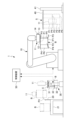
- FIG. 1 is a schematic diagram showing the configuration of a box folding system according to a first embodiment of the present disclosure.
- 2 is a flowchart showing a procedure for folding a box by the box folding system of FIG. 1.
- FIG. FIG. 2 is a schematic cross-sectional view illustrating one scene of the opening operation of the lower flap by the box folding system of FIG. 1;
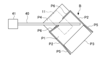
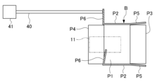
- FIG. 4 is a schematic cross-sectional view illustrating the next scene in FIG. 3 of the opening operation of the lower flap by the box folding system of FIG. 1;
- FIG. 5 is a schematic cross-sectional view illustrating the next scene in FIG. 4 of the opening operation of the lower flap by the box folding system of FIG. 1;
- FIG. 6 is a schematic sectional view illustrating the next scene in FIG. 5 of the opening operation of the lower flap by the box folding system of FIG. 1;
- FIG. 1 is a schematic diagram showing the configuration of a box folding system 1 according to a first embodiment of the present disclosure.
- the box folding system 1 is a system that flatly folds a box B formed from a box sheet S having a plurality of panels connected to each other.
- a 0201 type (formerly A-1 type) corrugated box is typically assumed, such as a grooved corrugated box specified by code number 02 of JIS-Z1507.
- the box sheet S of the 0201 type has a pair of length side panels P1 and a pair of width side panels P2 which are alternately connected laterally to form a rectangular cylindrical part, and an upper edge and a lower edge of P1 of the pair of length side panels.
- Two pairs of outer flaps (upper outer flap P3 and lower outer flap P4) each extend from the edge, and two pairs of inner flaps (upper inner flap P5) extend from the upper edge and lower edge of the pair of width panels P2, respectively. and a lower inner flap P6).
- the upper flaps P3 and P5 are combined to form a lid that seals the lower end of the square cylindrical part
- the lower flaps P4 and P6 are combined to seal the upper end of the square cylindrical part.
- the bottom body By forming the bottom body, it is assembled into a box B to be sealed. Note that terms such as “side,” “upper,” and “lower” that indicate the direction of the box sheet are merely used for convenience of explanation and the general orientation when the box B is used. The orientation of the box B in the box folding system 1 is not limited.
- the box folding system 1 includes a robot 10 that moves the box B, and an opening auxiliary member that opens either the outer flaps P3, P4 or the inner flaps P5, P6 when the robot 10 comes into contact with the moving box B. 20, a pad take-out device 30 that cooperates with the robot 10 to take out the buffer pad C placed in the box B, and the relative angle of the panel (especially the width side) when the robot 10 comes into contact with the moving box B.
- the device includes a folding auxiliary member 40 that changes the relative angle between the panel P2 and the inner flaps P5 and P6, and a control device 50 that controls the robot 10 and the pad take-out device 30.
- the robot 10 has a work head 11 at its end that sucks the box sheet S, and is configured to be able to move the box sheet S (including the assembled box body B) by changing the position and orientation of the work head 11. be done.
- a vertically articulated robot can be used as the robot 10, but other types of robots may also be used.
- the work head 11 may be configured to suction the box sheet S using a plurality of suction pads 12.
- the work head 11 is large enough to simultaneously hold two adjacent panels of the box sheet S (length side panel P1 and lower outer flap P4, or length side panel P1 and width side panel P2) in substantially the same plane. It is designed to have strong and suction power.
- the work head 11 includes a cutter 13 for cutting the tape that locks the outer flaps P3 and P4 in a sealed state, and a position for cutting the tape (outer flaps P3,
- the outer edge of P4 may also be provided with a sensor 14 for checking the outer edge of P4.
- the opening assisting member 20 has a width smaller than the lateral width of the length panel P1 and the width panel P2, and is formed to be insertable into the box B held by the robot 10. Further, it is preferable that the opening assisting member 20 has a length larger than the extension length of the flaps P3 to P6.
- the opening assisting member 20 is arranged to protrude upward. In this embodiment, the opening assisting member 20 is immovably fixed to the end of the table 21 to which the box B is supplied. In this embodiment, the table 21 is supplied with a box B whose lid (upper flaps P3, P5) has been opened and the articles inside have been taken out.
- the pad removal device 30 is inserted into the box B and includes a suction section 31 that suctions the buffer pad C, a support section 32 that supports the suction section 31 at its tip, and a pad confirmation section that determines the presence or absence of the buffer pad C. 33.
- the support part 32 supports the suction part 31 so as to be movable in the insertion direction (up and down direction) into the box B
- the pad confirmation part 33 has a sensor that detects movement of the suction part 31 with respect to the support part 32.
- the suction part 31 has a weight that allows the buffer pad C to be extracted from the box body B by its own weight
- the pad confirmation part 33 has a proximity switch etc. that detects that the suction part 31 is in the lowered position.
- the box B which is held upside down by the robot 10, is fitted into the pad takeout device 30. If the buffer pad C is not present, the suction section 31 suctions the bottom of the box B, and when the robot 10 lifts the box B, the suction section 31 is lifted together with the box B. Therefore, when the pad confirmation section 33 detects movement of the suction section 31, it can be determined that the buffer pad C does not exist.
- the pad removal device 30 is also used to hold the box body B when the robot 10 cuts the tape that locks the lower outer flap P4 that seals the bottom of the box body B. It will be done.
- the folding auxiliary member 40 is a rod-shaped body that is supported substantially horizontally in a cantilevered manner.
- the folding auxiliary member 40 is supported by the support column 41, but it may also be supported by a building or other structure.
- the folding auxiliary member 40 may be formed by a pipe or a bar.
- the diameter of the folding auxiliary member 40 is preferably as small as possible within a range that can ensure rigidity so that it can be inserted into the box body B in various orientations.
- the length of the folding auxiliary member 40 is determined by the height of the box sheet S in the folded state (the length of the height of the surface panel P1 and the vertical It is preferable that the total extension length of the outer flaps P3 and P4 is greater than or equal to the total extension length of the outer flaps P3 and P4.
- the folding auxiliary member 40 is placed at a position higher than the total horizontal length of one length panel P1 and one width panel P2 so that the box sheet S can be directed without contacting the floor surface. Preferably, it is retained.
- the control device 50 may be constituted by one or more computer devices having, for example, a memory, a processor, an input/output interface, etc., and executing an appropriate control program. Moreover, a part of the control device 50 may be configured by a physical circuit.
- the control device 50 controls the robot 10 and the pad take-out device 30 so that the box folding system 1 can fold the box B shown in FIG. 2 .
- the folding process of the box B includes a step of suctioning the bottom surface of the box B by the work head 11 (S01: bottom suction step), and a step of moving the box B so that the opening auxiliary member 20 opens the upper flaps P3 and P5.
- step (S02: upper flap opening step) step of arranging the box B on the pad take-out device 30 (S03: pad take-out device placement step), and suction step of the buffer pad C by the suction unit 31 of the pad take-out device 30.
- 40 (S11: Box release step), and a step of sucking the length side panel P1 and the width side panel P2 with the work head 11, folding the box sheet S,
- the bottom surface of the box B sealed with tape is suctioned by the work head 11.
- the bottom surface of the box B may be suctioned after the work head 11 once sucks the side surfaces of the box B and turns the box B sideways.
- the upper flaps P3 and P5 are brought into contact with the opening assisting member 20 one by one and rotated outward.
- the upper flaps P3 and P5 are bent so that they are each held in an outwardly open state. That is, the robot 10 inserts the opening auxiliary member 20 between the upper flaps P3 and P5, brings the opening auxiliary member 20 into contact with either of the upper flaps P3 and P5, and opens the box B so that its rectangular cylindrical portion is It is moved to a position where it does not overlap with the opening auxiliary member 20 in plan view. Further, the robot 10 preferably rotates the upper flaps P3 and P5 largely outward by moving the box B downward.
- the box B is fitted into the pad take-out device 30 by the robot 10. Thereby, the suction part 31 of the pad take-out device 30 is in a state where it supports the bottom body (lower flaps P4, P6) of the box body B from inside via the buffer pad C.
- the suction unit 31 starts suctioning, thereby suctioning the buffer pad C present inside the box B.
- the suction section 31 suctions the bottom body of the box body B.
- the robot 10 lifts the box B a little.
- the suction part 31 stays in place with the buffer pad C adsorbed by its own weight, and the bottom of the box B Separate the buffer pad C from the
- the robot 10 also lifts up the suction part 31 that is suctioning the bottom body of the box body B.
- the buffer pad presence/absence determination step of S06 it is determined whether or not to perform the suction stop step of S07 based on the detection result of the suction portion 31 by the pad confirmation section 33 in the box lifting step.
- the inner surface of the bottom body of the box B is released from the suction part 31 by stopping the suction of the suction part 31.
- the box body B is released from the work head 11, and the bottom surface of the box body B is cut using the cutter 13 of the work head 11 to enable opening of the lower outer flap P4 and eventually the lower inner flap P6. Cut the attached tape.
- the working head 11 is arranged so that a part thereof is located on one lower outer flap P4 and the remaining part protrudes to the outside of the box body B.
- the work head 11 is moved in a 90 degree arc so that the lower outer flap P4 is sucked by the work head 11 and the sucked lower outer flap P4 is swung around its base edge and released. let Thereby, the remaining part of the work head 11 can attract the longitudinal panel P1 adjacent to the lower outer flap P4. As a result, the work head 11 attracts and holds the lower outer flap P4 and the longitudinal panel P1 on the same virtual plane.
- the box body B can be removed from the pad take-out device 30, leaving the buffer pad C behind.
- the work head 11 picks up the longitudinal panel P1 and the connected outer flap P4 on the same plane, and opens the box body in a posture in which the other longitudinal panel P1 is placed on the lower side.
- the lower inner flap P6 is brought into contact with the folding auxiliary member 40 and opened.
- the robot 10 holds the box B so that the width panel P2 is inclined with respect to the folding auxiliary member 40, and moves the box B in the longitudinal direction of the folding auxiliary member 40.
- the tip of the folding auxiliary member 40 is inserted into the box B by moving the folding auxiliary member 40.
- the lower inner flap P6 located on the tip side of the folding auxiliary member 40 is not pushed into the inside of the box body B.
- the lower inner flap P6 located on the proximal end side of the folding auxiliary member 40 may be pushed slightly into the inside of the box body B.
- the robot 10 by using the robot 10 to pull out the box B in the direction along the width panel P2, the lower inner flap P6 located on the tip side of the folding auxiliary member 40 can be opened. Furthermore, the robot 10 moves the box body along a trajectory having a component in a direction along the lower edge of the longitudinal panel P1 within a range where the lower inner flap P6 located on the tip side of the folding assisting member 40 does not separate from the folding assisting member 40. By moving B, as shown in FIG. 5, the lower inner flap P6 is largely opened to the outside of the box body B, and the lower inner flap P6 is bent into the open state.
- the robot 10 inverts the inclination of the box B and the trajectory of the movement of the box B with respect to the folding auxiliary member 40 and moves the box B in the same manner, thereby moving the box B to the opposite side as shown in FIG.
- the lower inner flap P6 can also be folded in the open state.
- the box B is in a state where all the flaps P3 to P6 are arranged outside the rectangular cylindrical portion and can be easily folded so that one of the width panels P2 is superimposed on the length panel P1.
- the lower outer flap P4 that is not suctioned by the work head 11 can be opened by its own weight, but if the lower outer flap P4 has a strong tendency to fold, it must be suctioned by the work head 11 before opening the lower inner flap P6.
- the box body B may be moved so that the lower outer flap P4 which is not open is brought into contact with the folding auxiliary member 40 and opened.
- the box is released from the work head 11 so that the folding auxiliary member 40 supports the box sheet S at the boundary between the length panel P1 and the width panel P2. That is, by placing the box B on the folding auxiliary member 40, the box B is folded by its own weight, and the folded box sheet S is suspended from the folding auxiliary member 40.
- the robot 10 holds the length panel P1 and the adjacent width panel P2 on one side of the box sheet S supported by the folding auxiliary member 40 on substantially the same plane using the work head 11. While doing so, the box sheet S is pulled out from the folding auxiliary member 40. Due to the thickness of the folding auxiliary member 40, the boxed sheet S suspended from the folding auxiliary member 40 may be in an incompletely folded state with a slight inner cavity remaining. If it is difficult to hold the length panel P1 and the width panel P2 on the same plane in this state, first move the work head 11 toward the upper one of the length panel P1 and the width panel P2.
- the length panel P1 and the width panel P2 can be sucked onto the same plane by placing the panel at the center of the box sheet S in the vertical direction, and then rotating the work head 11 so that the suction surface is vertical. good.
- the box sheet S cannot be held in a substantially folded state even if the work head 11 is rotated so that the suction surfaces are horizontal. Therefore, the box sheets S folded by the robot 10 can be stacked in order at a predetermined location.
- the robot 10 moves the box B to bring the lower inner flap P6 into contact with the folding auxiliary member 40 and open it, so there is a high degree of tolerance for differences in the size of the box B. Even when folding the boxes B, which have a large size and have a large difference in size, there is a wide range that can be handled by simply changing the operation program of the robot 10.
- the box folding system according to the present disclosure is applied to a box whose bottom body (lower flap) is open when taking out an article, and the upper flap may be opened with a folding auxiliary member. . Furthermore, in the box folding system according to the present disclosure, both the upper flap and the lower flap may be opened using the folding auxiliary member. Therefore, in the box folding system according to the present disclosure, the release assisting member can be omitted. Further, in the box folding system according to the present disclosure, the pad take-out device is not an essential component, and the tape may be cut at a location other than the pad take-out device.
- the work head may not have a tape cutter, and the tape may be cut by a separately provided tape cutting mechanism such as a robot.
- the box folding system according to the present disclosure may be configured such that a robot different from the robot that opens the flap and causes the folding auxiliary member to hold the boxed sheet removes the box sheet from the folding auxiliary member.
- the robot may perform other tasks, such as taking out articles stored in the box or assisting therein.
Landscapes
- Engineering & Computer Science (AREA)
- Mechanical Engineering (AREA)
- Supplying Of Containers To The Packaging Station (AREA)
- Control And Other Processes For Unpacking Of Materials (AREA)
- Manipulator (AREA)
- Making Paper Articles (AREA)
Abstract
Description
10 ロボット
11 作業ヘッド
12 吸着パッド
13 カッタ
14 センサ
20 開放補助部材
21 テーブル
30 パッド取り出し装置
31 吸着部
32 支持部
33 パッド確認部
40 折り畳み補助部材
41 支柱
50 制御装置
B 箱体
C 緩衝パッド
P1 長さ面パネル
P2 幅面パネル
P3 上外フラップ
P4 下外フラップ
P5 上内フラップ
P6 下内フラップ
S 箱シート
Claims (6)
- 互いに連接される複数のパネルを有する箱シートから形成される箱体を折り畳む箱体折り畳みシステムであって、
前記箱シートを吸着する作業ヘッドを有し、前記箱体を移動するロボットと、
前記ロボットが移動する前記箱体に当接することにより前記パネルの相対角度を変更する折り畳み補助部材と、
を備える箱体折り畳みシステム。 - 前記折り畳み補助部材は、略水平に片持状態で支持される棒状体である、請求項1に記載の箱体折り畳みシステム。
- 前記複数のパネルは、側方に交互に連接されて四角筒状部を形成する一対の長さ面パネル及び一対の幅面パネルと、前記一対の長さ面パネルの上縁及び下縁からそれぞれ延出する二対の外フラップと、前記一対の幅面パネルの上縁及び下縁からそれぞれ延出する二対の内フラップと、を含み、
前記ロボットは、
前記作業ヘッドが前記長さ面パネル及び連接された前記外フラップを同一平面上で吸着してもう一方の前記長さ面パネルを下側に配置する姿勢で、前記折り畳み補助部材により前記内フラップを開放するよう前記箱体を移動し、
続いて、前記折り畳み補助部材に前記長さ面パネルと前記幅面パネルとの境界において前記箱シートを支持させるよう、前記作業ヘッドから前記箱体を解放する、
請求項2に記載の箱体折り畳みシステム。 - 前記ロボットは、前記折り畳み補助部材が支持する前記箱シートの一方の面側の前記長さ面パネル及び隣接する前記幅面パネルを前記作業ヘッドにより略同一平面上に保持する、請求項3に記載の箱体折り畳みシステム。
- 前記箱体の中に挿入され、前記箱体の中に配置される緩衝パッドを吸着する吸着部を有するパッド取り出し装置をさらに備える、請求項1から4のいずれかに記載の箱体折り畳みシステム。
- 前記パッド取り出し装置は、
前記吸着部を前記箱体への挿入方向に移動可能に支持する支持部と、
前記吸着部の前記支持部に対する移動を検知するパッド確認部と、
を有する、請求項5に記載の箱体折り畳みシステム。
Priority Applications (5)
| Application Number | Priority Date | Filing Date | Title |
|---|---|---|---|
| DE112022005617.7T DE112022005617T5 (de) | 2022-03-16 | 2022-03-16 | Kistenfaltsystem |
| US18/725,023 US12534248B2 (en) | 2022-03-16 | 2022-03-16 | Box folding system |
| JP2022533456A JP7174200B1 (ja) | 2022-03-16 | 2022-03-16 | 箱体折り畳みシステム |
| CN202280093277.6A CN118742490A (zh) | 2022-03-16 | 2022-03-16 | 箱体折叠系统 |
| PCT/JP2022/012071 WO2023175804A1 (ja) | 2022-03-16 | 2022-03-16 | 箱体折り畳みシステム |
Applications Claiming Priority (1)
| Application Number | Priority Date | Filing Date | Title |
|---|---|---|---|
| PCT/JP2022/012071 WO2023175804A1 (ja) | 2022-03-16 | 2022-03-16 | 箱体折り畳みシステム |
Publications (1)
| Publication Number | Publication Date |
|---|---|
| WO2023175804A1 true WO2023175804A1 (ja) | 2023-09-21 |
Family
ID=84100512
Family Applications (1)
| Application Number | Title | Priority Date | Filing Date |
|---|---|---|---|
| PCT/JP2022/012071 Ceased WO2023175804A1 (ja) | 2022-03-16 | 2022-03-16 | 箱体折り畳みシステム |
Country Status (5)
| Country | Link |
|---|---|
| US (1) | US12534248B2 (ja) |
| JP (1) | JP7174200B1 (ja) |
| CN (1) | CN118742490A (ja) |
| DE (1) | DE112022005617T5 (ja) |
| WO (1) | WO2023175804A1 (ja) |
Citations (3)
| Publication number | Priority date | Publication date | Assignee | Title |
|---|---|---|---|---|
| JP2000153816A (ja) * | 1998-11-19 | 2000-06-06 | Maejima Kogyo Kk | 箱体の折り畳み処理方法及び装置 |
| JP2018039181A (ja) * | 2016-09-07 | 2018-03-15 | 大森機械工業株式会社 | フラップ折込装置及び折込方法 |
| JP2018043786A (ja) * | 2016-09-16 | 2018-03-22 | 大日本印刷株式会社 | 箱解体用治具 |
Family Cites Families (4)
| Publication number | Priority date | Publication date | Assignee | Title |
|---|---|---|---|---|
| JPS5254525U (ja) | 1975-10-16 | 1977-04-19 | ||
| JP2551295B2 (ja) | 1992-03-06 | 1996-11-06 | 東洋製罐株式会社 | 段ボール箱の自動開箱、物品取り出し、折畳方法及び装置 |
| JP5545357B2 (ja) * | 2012-12-25 | 2014-07-09 | 株式会社安川電機 | ロボットシステムおよびロボット |
| JP7143018B2 (ja) * | 2018-05-30 | 2022-09-28 | 川崎重工業株式会社 | 箱詰装置 |
-
2022
- 2022-03-16 US US18/725,023 patent/US12534248B2/en active Active
- 2022-03-16 CN CN202280093277.6A patent/CN118742490A/zh active Pending
- 2022-03-16 JP JP2022533456A patent/JP7174200B1/ja active Active
- 2022-03-16 DE DE112022005617.7T patent/DE112022005617T5/de active Pending
- 2022-03-16 WO PCT/JP2022/012071 patent/WO2023175804A1/ja not_active Ceased
Patent Citations (3)
| Publication number | Priority date | Publication date | Assignee | Title |
|---|---|---|---|---|
| JP2000153816A (ja) * | 1998-11-19 | 2000-06-06 | Maejima Kogyo Kk | 箱体の折り畳み処理方法及び装置 |
| JP2018039181A (ja) * | 2016-09-07 | 2018-03-15 | 大森機械工業株式会社 | フラップ折込装置及び折込方法 |
| JP2018043786A (ja) * | 2016-09-16 | 2018-03-22 | 大日本印刷株式会社 | 箱解体用治具 |
Also Published As
| Publication number | Publication date |
|---|---|
| CN118742490A (zh) | 2024-10-01 |
| JP7174200B1 (ja) | 2022-11-17 |
| DE112022005617T5 (de) | 2024-09-12 |
| JPWO2023175804A1 (ja) | 2023-09-21 |
| US20250100731A1 (en) | 2025-03-27 |
| US12534248B2 (en) | 2026-01-27 |
Similar Documents
| Publication | Publication Date | Title |
|---|---|---|
| DK3046843T3 (en) | Case erector | |
| JP5351946B2 (ja) | 梱包装置 | |
| JP6112191B2 (ja) | 梱包装置および梱包方法 | |
| US20140371045A1 (en) | Device and Method for Preparing Packaging Boxes With Vertical Unstacking | |
| US20210253287A1 (en) | Box assembling and packing system and controller for said system | |
| JP6676968B2 (ja) | 中仕切り挿入装置 | |
| CN112839777A (zh) | 末端执行器和安装有它的机器人 | |
| US20090025343A1 (en) | Method of providing erected folding boxes at the exit of a manufacturing machine and apparatus for erecting folding boxes from flat folding box sheath | |
| JP5933955B2 (ja) | 製函装置 | |
| JPH09131685A (ja) | ロボットのハンド装置 | |
| WO2021079940A1 (ja) | 荷降し装置、及び、荷降し方法 | |
| JP6800767B2 (ja) | 組立装置および組立方法 | |
| US20190375521A1 (en) | Boxing device and boxing method | |
| WO2023175804A1 (ja) | 箱体折り畳みシステム | |
| JP2009012859A (ja) | カートンマガジン、カートンハンド及び文書積載挿入装置 | |
| JPH02139227A (ja) | ダンボール製函方法およびダンボール製函機 | |
| JP2021127250A (ja) | 卵パックを移載するロボットシステムおよび移動式のラックに複数段に積まれた状態の卵パックを生産する方法 | |
| JP4081513B2 (ja) | 作業ロボット装置 | |
| JP2005119730A (ja) | ロボット式ケーサ | |
| JPH0278534A (ja) | ダンボール製函方法、ダンボール製函機および開函機構 | |
| JP2810949B2 (ja) | 箱の開梱方法及び装置 | |
| JP4505969B2 (ja) | カートン起函装置 | |
| JP2023110391A (ja) | カートン自動供給装置 | |
| JP2017056977A (ja) | 箱詰装置 | |
| JP7026948B2 (ja) | 組立装置、箱詰め装置および組立方法 |
Legal Events
| Date | Code | Title | Description |
|---|---|---|---|
| WWE | Wipo information: entry into national phase |
Ref document number: 2022533456 Country of ref document: JP |
|
| 121 | Ep: the epo has been informed by wipo that ep was designated in this application |
Ref document number: 22932080 Country of ref document: EP Kind code of ref document: A1 |
|
| WWE | Wipo information: entry into national phase |
Ref document number: 18725023 Country of ref document: US |
|
| WWE | Wipo information: entry into national phase |
Ref document number: 202280093277.6 Country of ref document: CN |
|
| 122 | Ep: pct application non-entry in european phase |
Ref document number: 22932080 Country of ref document: EP Kind code of ref document: A1 |
|
| WWP | Wipo information: published in national office |
Ref document number: 18725023 Country of ref document: US |
|
| WWG | Wipo information: grant in national office |
Ref document number: 18725023 Country of ref document: US |