WO2023171825A1 - 固体電解質、固体電解質層及び固体電解質電池 - Google Patents
固体電解質、固体電解質層及び固体電解質電池 Download PDFInfo
- Publication number
- WO2023171825A1 WO2023171825A1 PCT/JP2023/009673 JP2023009673W WO2023171825A1 WO 2023171825 A1 WO2023171825 A1 WO 2023171825A1 JP 2023009673 W JP2023009673 W JP 2023009673W WO 2023171825 A1 WO2023171825 A1 WO 2023171825A1
- Authority
- WO
- WIPO (PCT)
- Prior art keywords
- solid electrolyte
- coo
- positive electrode
- ooc
- negative electrode
- Prior art date
- Legal status (The legal status is an assumption and is not a legal conclusion. Google has not performed a legal analysis and makes no representation as to the accuracy of the status listed.)
- Ceased
Links
Images


Classifications
-
- H—ELECTRICITY
- H01—ELECTRIC ELEMENTS
- H01B—CABLES; CONDUCTORS; INSULATORS; SELECTION OF MATERIALS FOR THEIR CONDUCTIVE, INSULATING OR DIELECTRIC PROPERTIES
- H01B1/00—Conductors or conductive bodies characterised by the conductive materials; Selection of materials as conductors
- H01B1/06—Conductors or conductive bodies characterised by the conductive materials; Selection of materials as conductors mainly consisting of other non-metallic substances
- H01B1/08—Conductors or conductive bodies characterised by the conductive materials; Selection of materials as conductors mainly consisting of other non-metallic substances oxides
-
- H—ELECTRICITY
- H01—ELECTRIC ELEMENTS
- H01M—PROCESSES OR MEANS, e.g. BATTERIES, FOR THE DIRECT CONVERSION OF CHEMICAL ENERGY INTO ELECTRICAL ENERGY
- H01M10/00—Secondary cells; Manufacture thereof
- H01M10/05—Accumulators with non-aqueous electrolyte
- H01M10/056—Accumulators with non-aqueous electrolyte characterised by the materials used as electrolytes, e.g. mixed inorganic/organic electrolytes
- H01M10/0561—Accumulators with non-aqueous electrolyte characterised by the materials used as electrolytes, e.g. mixed inorganic/organic electrolytes the electrolyte being constituted of inorganic materials only
- H01M10/0562—Solid materials
-
- H—ELECTRICITY
- H01—ELECTRIC ELEMENTS
- H01M—PROCESSES OR MEANS, e.g. BATTERIES, FOR THE DIRECT CONVERSION OF CHEMICAL ENERGY INTO ELECTRICAL ENERGY
- H01M10/00—Secondary cells; Manufacture thereof
- H01M10/05—Accumulators with non-aqueous electrolyte
- H01M10/052—Li-accumulators
-
- H—ELECTRICITY
- H01—ELECTRIC ELEMENTS
- H01M—PROCESSES OR MEANS, e.g. BATTERIES, FOR THE DIRECT CONVERSION OF CHEMICAL ENERGY INTO ELECTRICAL ENERGY
- H01M2300/00—Electrolytes
- H01M2300/0017—Non-aqueous electrolytes
- H01M2300/0065—Solid electrolytes
- H01M2300/0068—Solid electrolytes inorganic
- H01M2300/0071—Oxides
- H01M2300/0074—Ion conductive at high temperature
- H01M2300/0077—Ion conductive at high temperature based on zirconium oxide
-
- H—ELECTRICITY
- H01—ELECTRIC ELEMENTS
- H01M—PROCESSES OR MEANS, e.g. BATTERIES, FOR THE DIRECT CONVERSION OF CHEMICAL ENERGY INTO ELECTRICAL ENERGY
- H01M2300/00—Electrolytes
- H01M2300/0017—Non-aqueous electrolytes
- H01M2300/0065—Solid electrolytes
- H01M2300/0068—Solid electrolytes inorganic
- H01M2300/008—Halides
-
- Y—GENERAL TAGGING OF NEW TECHNOLOGICAL DEVELOPMENTS; GENERAL TAGGING OF CROSS-SECTIONAL TECHNOLOGIES SPANNING OVER SEVERAL SECTIONS OF THE IPC; TECHNICAL SUBJECTS COVERED BY FORMER USPC CROSS-REFERENCE ART COLLECTIONS [XRACs] AND DIGESTS
- Y02—TECHNOLOGIES OR APPLICATIONS FOR MITIGATION OR ADAPTATION AGAINST CLIMATE CHANGE
- Y02E—REDUCTION OF GREENHOUSE GAS [GHG] EMISSIONS, RELATED TO ENERGY GENERATION, TRANSMISSION OR DISTRIBUTION
- Y02E60/00—Enabling technologies; Technologies with a potential or indirect contribution to GHG emissions mitigation
- Y02E60/10—Energy storage using batteries
Definitions
- the present invention relates to a solid electrolyte, a solid electrolyte layer, and a solid electrolyte battery.
- solid electrolytes oxide-based solid electrolytes, sulfide-based solid electrolytes, complex hydride-based solid electrolytes, halide-based solid electrolytes, and the like are known.
- Non-Patent Document 1 describes that the ionic conductivity of Li 3 ScCl 6 , which is a halide solid electrolyte, is 3 mS/cm, and the potential window on the reduction side is 0.91 V (V vs. Li/Li + ).
- Halide-based solid electrolytes are said to have higher ionic conductivity than oxide-based solid electrolytes, sulfide-based solid electrolytes, complex hydride-based solid electrolytes, and the like.
- the ionic conductivity (3 mS/cm) of Li 3 ScCl 6 described in Non-Patent Document 1 is high, it is subject to various limitations, and there are cases where the characteristics described in Non-Patent Document 1 are not expressed as they are, or when another material is selected. Sometimes it is unavoidable. Therefore, there is a need for a configuration that can relatively improve ionic conductivity in solid electrolytes with similar structures.
- the present invention was made in view of the above problems, and aims to provide a solid electrolyte, a solid electrolyte layer, and a solid electrolyte battery that can improve ionic conductivity.
- the solid electrolyte according to the first aspect includes Li a A b E c (SO 4 ) d J e X f H h (1).
- A is at least one element selected from alkali metals and alkaline earth metals other than Li
- E is Al, Ga, In, Sc, Y, Ti, Zr, Hf, and lanthanoids.
- J is at least one element selected from the group consisting of OH, BO 2 , BO 3 , BO 4 , B 3 O 6 , B 4 O 7 , CO 3 , NO 3 , AlO 2 , SiO 3 , SiO4 , Si2O7 , Si3O9 , Si4O11 , Si6O18 , PO3 , PO4 , P2O7 , P3O10 , SO3 , SO5 , S2O3 , S2O4 , S2O5 , S2O6 , S2O7 , S2O8 , BF4 , PF6 , BOB , (COO) 2 , N, AlCl4 , CF3SO3 , CH3 COO, CF 3 COO, OOC-(CH 2 ) 2 -COO, OOC-CH 2 -COO, OOC-CH(OH)-CH(OH)-COO, OOC-CH(OH)-CH 2 -COO, O
- the solid electrolyte according to the above aspect may have an ionic conductivity of 1 mS/cm or more at 25°C.
- the solid electrolyte layer according to the second aspect includes the solid electrolyte according to the above aspect.
- a solid electrolyte battery includes a negative electrode, a positive electrode, and a solid electrolyte layer that is located between the negative electrode and the positive electrode and includes a solid electrolyte. At least one of the negative electrode, the positive electrode, and the solid electrolyte layer includes the solid electrolyte according to the above embodiment.
- a solid electrolyte battery according to a fourth aspect includes a negative electrode, a positive electrode, and a solid electrolyte layer according to the above aspect located between the negative electrode and the positive electrode.
- the solid electrolyte according to the above embodiment can improve ionic conductivity.
- FIG. 1 is a schematic cross-sectional view of a solid electrolyte battery 100 according to the present embodiment.
- the X-ray diffraction results of Comparative Example 4 are shown. It is a charge-discharge curve of Example 4 and Comparative Examples 3 and 4.
- Solid electrolyte A solid electrolyte is a substance that can move ions by applying an external electric field. When the ionic conductivity of the solid electrolyte is high, the transfer of ions in the solid electrolyte battery becomes smooth and the internal resistance becomes small.
- the solid electrolyte includes a halide solid electrolyte represented by Li a A b E c (SO 4 ) d J e X f H h (1).
- the solid electrolyte may also contain a material derived from the raw material powder.
- the substance originating from the raw material powder is, for example, Li 2 SO 4 .
- the solid electrolyte may be in the form of powder (particles) or may be in the form of a sintered body obtained by sintering the powder.
- solid electrolytes can be made by compressing powder, molding a mixture of powder and binder, or applying a paint containing powder, binder, and solvent and then heating to remove the solvent. A formed coating film may also be used.
- the main structure of the solid electrolyte may be amorphous or crystalline.
- Li is a lithium ion. a satisfies 0.5 ⁇ a ⁇ 6, preferably 2.0 ⁇ a ⁇ 4.0, and more preferably 2.5 ⁇ a ⁇ 3.5. When E is Zr or Hf, a is preferably 1.0 ⁇ a ⁇ 3.0, more preferably 1.5 ⁇ a ⁇ 2.5. In the compound represented by formula (1), if a is 0.5 ⁇ a ⁇ 6, the content of Li contained in the compound will be appropriate, and the ionic conductivity of the solid electrolyte layer 10 will be high.
- A is at least one element selected from alkali metals and alkaline earth metals other than Li.
- A is substituted with a portion of Li ions.
- A is, for example, Na or Ca.
- b satisfies 0 ⁇ b ⁇ 6. Further, a+b satisfies 0.5 ⁇ a+b ⁇ 6.
- E is an essential component and includes Al, Ga, In, Sc, Y, Ti, Zr, Hf, lanthanoids (La, Ce, Pr, Nd, Pm, Sm, Eu, Gd, Tb , Dy, Ho, Er, Tm, Yb, Lu).
- E preferably contains Al, Sc, Y, Zr, Hf, and La, and more preferably contains Zr and Y.
- E improves the ionic conductivity of the solid electrolyte.
- c is 0 ⁇ b ⁇ 2. Since the effect of including E can be obtained more effectively, c is preferably 0.6 ⁇ c.
- E is an element that forms the skeleton of the solid electrolyte. More preferably, c satisfies c ⁇ 1.
- SO 4 is sulfate.
- d satisfies 0.1 ⁇ d ⁇ 6.0, preferably satisfies 0.2 ⁇ d ⁇ 4.0, and more preferably satisfies 0.4 ⁇ d ⁇ 2.5.
- the potential window on the reduction side of the solid electrolyte becomes wider, making it difficult to be reduced.
- J is, for example, OH, BO 2 , BO 3 , BO 4 , B 3 O 6 , B 4 O 7 , CO 3 , NO 3 , AlO 2 , SiO 3 , SiO 4 , Si 2 O 7 , Si3O9 , Si4O11 , Si6O18 , PO3 , PO4 , P2O7 , P3O10 , SO3 , SO5 , S2O3 , S2O4 , S 2O5 , S2O6 , S2O7 , S2O8 , BF4 , PF6 , BOB ( bisoxalate borate), (COO) 2 , N , AlCl4 , CF3SO3 , CH 3 COO, CF 3 COO, OOC-(CH 2 ) 2 -COO (succinate), OOC-CH 2 -COO (malonate), OOC-CH(OH)-CH(OH)-COO (tartrate)
- e satisfies 0 ⁇ e ⁇ 6. It is preferable that e satisfies 0.5 ⁇ e because the effect of widening the potential window on the reduction side by including J becomes more pronounced. It is preferable that e ⁇ 3 so that the ionic conductivity of the solid electrolyte does not decrease due to too much J content. Further, d+e satisfies 0.1 ⁇ d ⁇ 6.0.
- X is at least one selected from the group consisting of F, Cl, Br, and I.
- X is preferably at least one member selected from the group consisting of Cl, Br, and I, preferably containing Br and/or I, and particularly containing I. It is preferable to include.
- F it preferably contains F and two or more selected from the group consisting of Cl, Br, and I, since X becomes a solid electrolyte with high ionic conductivity.
- the solid electrolyte When X is F, the solid electrolyte has sufficiently high ionic conductivity and excellent oxidation resistance. When X is Cl, the solid electrolyte has high ionic conductivity and a good balance between oxidation resistance and reduction resistance. When X is Br, the solid electrolyte has sufficiently high ionic conductivity and a good balance between oxidation resistance and reduction resistance. When X is I, the solid electrolyte has high ionic conductivity.
- f satisfies 0 ⁇ f ⁇ 6.1. It is preferable that d satisfies 1 ⁇ f.
- f is 1 ⁇ d, the strength of the pellet increases when the solid electrolyte is press-molded into a pellet. Moreover, when f is 1 ⁇ f, the ionic conductivity of the solid electrolyte becomes high. Further, f is preferably f ⁇ 5 so that the potential window of the solid electrolyte does not become narrow due to insufficient sulfate due to too large a content of X.
- H is hydrogen. h satisfies 0 ⁇ h ⁇ 0.2.
- the solid electrolyte is, for example, Li 2 ZrSO 4 Cl 4 , Li 3 YSO 4 Cl 4 , Li 3 ScSO 4 Cl 4 , Li 3 InSO 4 Cl 4 .
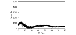
- FIG. 1 shows the results of X-ray diffraction (XRD) of the solid electrolyte according to this embodiment.
- the vertical axis in FIG. 1 is intensity, and the horizontal axis is 2 ⁇ .
- X-ray diffraction was performed using a Cu- ⁇ source.
- the X-ray diffraction pattern shown in FIG. 1 is obtained by removing the background data of the polyimide tape from the measurement results.
- FIG. 1 shows the X-ray diffraction results of Example 4, which will be described later.
- peaks are considered to be peaks derived from Li 2 SO 4 which is a raw material used when producing the compound of formula (1).
- FIG. 2 is an X-ray diffraction result of a solid electrolyte containing the compound of formula (1).
- the X-ray diffraction pattern shown in FIG. 2 is the measured raw data without removing the background data of the polyimide tape. The further you go from the front to the back of the page, the more the reactions between the raw materials progress.
- 3A and 3B are graphs showing the results of X-ray photoelectron spectroscopy of the solid electrolyte according to the present embodiment, in which the range in which the peak occurs is expanded.
- peaks are observed at, for example, 170 ⁇ 0.5 eV and 532 ⁇ 0.5 eV.
- the peak at 170 ⁇ 0.5eV is the peak derived from S2p of sulfur, which is confirmed when there is a structure in which sulfur and oxygen are bonded
- the peak at 532 ⁇ 0.5eV is the peak in which there is a structure in which sulfur and oxygen are bonded.
- This is a peak derived from oxygen O1s that is confirmed when there is oxygen. That is, it can be said that the solid electrolyte has a portion having an SO 4 structure, and this structure is thought to originate from the unreacted raw material powder (LiSO 4 ).
- the solid electrolyte according to this embodiment has a specific peak confirmed by X-ray diffraction and has high ionic conductivity.
- the ionic conductivity of the solid electrolyte according to this embodiment is 1 mS/cm or more. It is not clear why the ionic conductivity increases when the solid electrolyte has a specific peak in X-ray diffraction, but the remaining crystalline LiSO4 creates a microstructure within the solid electrolyte that has channels through which Li ions can conduct. It is thought that this is because it serves as a starting point for formation.
- FIG. 4 is a schematic cross-sectional view of the solid electrolyte battery 100 according to this embodiment.
- the solid electrolyte battery 100 shown in FIG. 4 includes a power generation element 40 and an exterior body 50. Exterior body 50 covers the periphery of power generation element 40 .
- the power generation element 40 is connected to the outside through a pair of connected terminals 60 and 62.
- FIG. 1 shows a stacked type battery, a wound type battery may also be used.
- the solid electrolyte battery 100 is used, for example, as a laminate battery, a square battery, a cylindrical battery, a coin battery, a button battery, or the like.
- the power generating element 40 includes a solid electrolyte layer 10, a positive electrode 20, and a negative electrode 30.
- the power generating element 40 is charged or discharged by transferring ions between the positive electrode 20 and the negative electrode 30 via the solid electrolyte layer 10 and transferring electrons via an external circuit.
- Solid electrolyte layer 10 is sandwiched between positive electrode 20 and negative electrode 30.
- the solid electrolyte layer 10 includes a solid electrolyte that can move ions by an externally applied voltage.
- solid electrolytes conduct lithium ions and inhibit the movement of electrons.
- the solid electrolyte layer 10 is, for example, a halide solid electrolyte.
- the solid electrolyte layer 10 includes, for example, the solid electrolyte described above.
- the solid electrolyte contained in the solid electrolyte layer 10 may not be the one described above.
- the positive electrode 20 includes a plate-shaped (foil-shaped) positive electrode current collector 22 and a positive electrode mixture layer 24.
- the positive electrode mixture layer 24 is in contact with at least one surface of the positive electrode current collector 22 .
- the positive electrode current collector 22 may be made of an electronically conductive material that can withstand oxidation during charging and is resistant to corrosion.
- the positive electrode current collector 22 is made of, for example, metal such as aluminum, stainless steel, nickel, or titanium, or conductive resin.
- the positive electrode current collector 22 may be in the form of powder, foil, punching, or expanded.
- the positive electrode mixture layer 24 contains a positive electrode active material, and, if necessary, a solid electrolyte, a binder, and a conductive aid.
- the positive electrode active material is not particularly limited as long as it is capable of reversibly occluding, deintercalating, and deintercalating lithium ions (intercalation/deintercalation), and can be used in known solid electrolyte batteries. It is possible to use the cathode active material that has been developed. Examples of the positive electrode active material include lithium-containing metal oxides and lithium-containing metal phosphorus oxides.
- the positive electrode active material may not contain lithium.
- Such positive electrode active materials include lithium-free metal oxides ( MnO2 , V2O5 , etc.), lithium-free metal sulfides ( MoS2, etc.), lithium-free fluorides ( FeF3 , VF3 , etc.). ), etc.
- the negative electrode is doped with lithium ions in advance, or a negative electrode containing lithium ions is used.
- the solid electrolyte included in the positive electrode 20 is, for example, the solid electrolyte described above.
- the solid electrolyte included in the positive electrode 20 may be a halide solid electrolyte other than the solid electrolyte described above.
- the content of the solid electrolyte in the positive electrode mixture layer 24 is not particularly limited, but may be 1% by mass to 50% by mass based on the total mass of the positive electrode active material, solid electrolyte, conductive aid, and binder. It is preferably 5% by mass to 30% by mass.
- the binder mutually binds the positive electrode active material, solid electrolyte, and conductive aid in the positive electrode mixture layer 24, and also firmly adheres the positive electrode mixture layer 24 and the positive electrode current collector 22. It is preferable that the positive electrode mixture layer 24 contains a binder. It is preferable that the binder has oxidation resistance and good adhesiveness.
- the binder used in the positive electrode mixture layer 24 includes polyvinylidene fluoride (PVDF) or its copolymer, polytetrafluoroethylene (PTFE), polyamide (PA), polyimide (PI), polyamideimide (PAI), polybenzimidazole ( PBI), polyethersulfone (PES), polyacrylic acid (PA) and its copolymers, metal ion crosslinked products of polyacrylic acid (PA) and its copolymers, polypropylene (PP) grafted with maleic anhydride , polyethylene (PE) grafted with maleic anhydride, or a mixture thereof.
- PVDF polyvinylidene fluoride
- PTFE polytetrafluoroethylene
- PA polyamide
- PI polyimide
- PAI polyamideimide
- PBI polybenzimidazole
- PES polyethersulfone
- PA polyacrylic acid
- PA polypropylene
- PP polypropylene
- PE polyethylene
- the content of the binder in the positive electrode mixture layer 24 is not particularly limited, but is preferably 1% by mass to 15% by mass based on the total mass of the positive electrode active material, solid electrolyte, conductive aid, and binder. , more preferably 3% by mass to 5% by mass. If the amount of binder is too small, there is a tendency that the positive electrode 20 with sufficient adhesive strength cannot be formed. On the other hand, if the amount of binder is too large, general binders are electrochemically inert and therefore do not contribute to discharge capacity, making it difficult to obtain sufficient volume or mass energy density.
- the conductive additive improves the electronic conductivity of the positive electrode mixture layer 24.
- a known conductive agent can be used.
- the conductive aid is, for example, a carbon material such as carbon black, graphite, carbon nanotube, or graphene, a metal such as aluminum, copper, nickel, stainless steel, iron, or an amorphous metal, a conductive oxide such as ITO, or a mixture thereof. be.
- the conductive aid may be in the form of powder or fiber.
- the content of the conductive additive in the positive electrode mixture layer 24 is not particularly limited.
- the mass ratio of the conductive aid is usually 0.5% to 20% by mass based on the total mass of the positive electrode active material, solid electrolyte, conductive aid, and binder.
- the amount is preferably 1% by mass to 5% by mass.
- the negative electrode 30 includes a negative electrode current collector 32 and a negative electrode mixture layer 34.
- the negative electrode mixture layer 34 is in contact with the negative electrode current collector 32 .
- the negative electrode current collector 32 only needs to have electron conductivity.
- the negative electrode current collector 32 is, for example, metal such as copper, aluminum, nickel, stainless steel, or iron, or conductive resin.
- the negative electrode current collector 32 may be in the form of powder, foil, punching, or expanded.
- the negative electrode mixture layer 34 contains a negative electrode active material, and if necessary, a solid electrolyte, a binder, and a conductive aid.
- the negative electrode active material is not particularly limited as long as it is capable of reversibly occluding and deintercalating lithium ions and intercalating and deintercalating lithium ions.
- negative electrode active materials used in known solid electrolyte batteries can be used.
- the negative electrode active material examples include natural graphite, artificial graphite, mesocarbon microbeads, mesocarbon fiber (MCF), coke, glassy carbon, carbon materials such as organic compound fired bodies, Si, SiO x , Sn, aluminum, etc. These include metals that can be combined with lithium, alloys thereof, composite materials of these metals and carbon materials, oxides such as lithium titanate (Li 4 Ti 5 O 12 ) and SnO 2 , metallic lithium, and the like.
- the negative electrode active material is preferably natural graphite.
- the solid electrolyte included in the negative electrode 30 is, for example, the solid electrolyte described above.
- the solid electrolyte included in the negative electrode 30 may be a halide solid electrolyte other than the solid electrolyte described above.
- the binder and conductive aid contained in the negative electrode 30 are the same as the binder and conductive aid contained in the positive electrode 20.
- the exterior body 50 houses the power generation element 40 therein.
- the exterior body 50 prevents moisture from entering from the outside to the inside.
- the exterior body 50 includes a metal foil 52 and a resin layer 54 laminated on each surface of the metal foil 52.
- the exterior body 50 is a metal laminate film in which a metal foil 52 is coated with resin layers 54 on both sides.
- the metal foil 52 is, for example, aluminum foil or stainless steel foil.
- a resin film made of polypropylene or the like can be used, for example.
- the material constituting the resin layer 54 may be different between the inside and outside.
- a high melting point polymer such as polyethylene terephthalate (PET), polyamide (PA), etc. can be used as the outer material, and polyethylene (PE), polypropylene (PP), etc. can be used as the inner material.
- Terminals 60 and 62 are connected to positive electrode 20 and negative electrode 30, respectively.
- Terminal 60 connected to positive electrode 20 is a positive electrode terminal
- terminal 62 connected to negative electrode 30 is a negative electrode terminal.
- Terminals 60 and 62 are responsible for electrical connection with the outside.
- the terminals 60, 62 are made of a conductive material such as aluminum, nickel, copper, or the like. The connection method may be welding or screwing.
- the terminals 60, 62 are preferably protected with insulating tape to prevent short circuits.
- the solid electrolyte can be manufactured, for example, by a method of mixing raw material powders containing a predetermined element at a predetermined molar ratio and causing a mechanochemical reaction. Adjustment is made so that unreacted raw materials remain in the solid electrolyte when performing a mechanochemical reaction. Specifically, unreacted components of the raw material can be made to remain by changing the rotation speed, revolution speed, synthesis time, and state of the raw material powder at the time of input of the planetary ball mill.
- the raw material powder contains a halide raw material
- the halide raw material tends to evaporate when the temperature is raised. Therefore, halogen gas may be present in the atmosphere during sintering to supplement the halogen.
- sintering may be performed by a hot press method using a highly airtight mold. In this case, since the mold is highly airtight, evaporation of the halide raw material due to sintering can be suppressed. By sintering in this manner, a solid electrolyte in the form of a sintered body made of a compound having a predetermined composition can be obtained.
- the positive electrode 20 is prepared.
- the positive electrode is manufactured by applying a paste containing a positive electrode active material onto the positive electrode current collector 22 and drying it to form the positive electrode mixture layer 24.
- the solid electrolyte described above may be added to the paste containing the positive electrode active material.
- the negative electrode 30 is prepared.
- the negative electrode is manufactured by applying a paste containing a negative electrode active material onto the negative electrode current collector 32 and drying it to form a negative electrode mixture layer 34.
- the solid electrolyte described above may be added to the paste containing the negative electrode active material.
- the power generation element 40 can be manufactured using, for example, a powder molding method.
- a guide having a hole is placed above the positive electrode 20, and a solid electrolyte is filled in the guide. Thereafter, the surface of the solid electrolyte is leveled, and the negative electrode 30 is placed on top of the solid electrolyte. As a result, the solid electrolyte is sandwiched between the positive electrode 20 and the negative electrode 30. Thereafter, pressure is applied to the positive electrode 20 and the negative electrode 30 to pressure mold the solid electrolyte.
- pressure molding a laminate in which the positive electrode 20, the solid electrolyte layer 10, and the negative electrode 30 are laminated in this order is obtained.
- the solid electrolyte battery 100 includes the above-described solid electrolyte, conduction of Li ions is smooth and internal resistance is low.
- Example 1 preparation of solid electrolyte
- the raw material powder was weighed so that the molar ratio of zirconium chloride (ZrCl 4 ) and lithium sulfate (Li 2 SO 4 ) was 1:8.
- ZrCl 4 zirconium chloride
- Li 2 SO 4 before mixing was pulverized for 1 hour using a planetary ball mill. The rotation speed during pulverization was 300 rpm.
- the raw material powder was introduced into a zirconia airtight container for a planetary ball mill in which zirconia balls had been placed in advance.
- the airtight container was covered with a lid, the lid was screwed to the container body, and the space between the lid and the container was further sealed with polyimide tape.
- Polyimide tape has the effect of blocking moisture.
- the zirconia airtight container was set in a planetary ball mill. The raw material powders were mixed at an autorotation speed of 200 rpm and a revolution speed of 200 rpm, with the rotation direction of the autorotation and the rotation direction of the revolution being opposite to each other, and a mechanochemical reaction was performed for 2 hours to form a solid electrolyte (Li 4 Zr 0.25 (SO 4 ) 2Cl ) was produced.
- Planetary ball mills are usually installed in the atmosphere (atmosphere).
- Zirconia airtight containers for planetary ball mills are screwed together and sealed with polyimide tape, so when a zirconia airtight container is set in a planetary ball mill, the zirconia airtight container is firmly pressed into place. Even in a normal atmosphere, it is thought that almost no moisture enters the zirconia sealed container from the atmosphere.
- XPS measurement In addition, X-ray photoelectron spectroscopy measurements were also performed. Sampling was carried out in a glove box with a dew point of about -70°C in which argon gas was circulated, and the sample was transported to an XPS measuring device without being exposed to the atmosphere. The XPS measurement was performed using Quantera 2 manufactured by PHI. As a result, peaks were confirmed at 170 ⁇ 0.5 eV and 532 ⁇ 0.5 eV in the produced solid electrolyte.
- the pressure molding die consists of a PEEK (polyetheretherketone) cylinder with a diameter of 10 mm, and an upper punch and a lower punch made of SKD11 material with a diameter of 9.99 mm.
- PEEK polyetheretherketone
- a stainless steel disk with a diameter of 50 mm and a thickness of 5 mm and a Teflon (trademark registered) disk with four screw holes were prepared, and a pressure molding die was set as follows.
- the stainless steel disc/Teflon (registered trademark) disc/die after pressure molding/Teflon (registered trademark) disc/stainless steel disc were loaded in this order, and the four screws were tightened with a torque of approximately 3 N m. .
- screws were inserted into the screw holes provided on the sides of the upper and lower punches to serve as external connection terminals.
- the external connection terminal was connected to a potentiostat (VersaSTAT3 manufactured by Princeton Applied Research) equipped with a frequency response analyzer, and the ionic conductivity was measured using an impedance measurement method. Measurement was performed in a measurement frequency range of 1 MHz to 0.1 Hz, an amplitude of 10 mV, and a temperature of 25°C.
- the ionic conductivity of the solid electrolyte of Example 1 was 1.1 ⁇ 10 ⁇ 3 S/cm.
- Example 2 to 8 Examples 2 to 8 differ from Example 1 in that the materials and molar ratio of the raw powder were changed. In Examples 2 to 8, the solid electrolyte was measured in the same manner as in Example 1. The composition, molar ratio, and measurement results of each raw material are listed in Table 1 below.
- Example 9 to 21 Examples 9 to 21 differ from Example 1 in that the materials and molar ratio of the raw material powder were changed, and the manufacturing conditions of the solid electrolyte were changed. In Examples 9 to 21, the solid electrolyte was measured in the same manner as in Example 1.
- Examples 9 to 21 were produced using the following procedure. First, in a glove box with a dew point of approximately ⁇ 75° C., zirconium chloride (ZrCl 4 ), lithium sulfate (Li 2 SO 4 ), and other raw materials were weighed to have predetermined molar ratios. Next, the Li 2 SO 4 before mixing was pulverized for 1 hour at a rotation speed of 300 rpm using a planetary ball mill, and then ZrCl 4 was added and further pulverized for 1 hour at a rotation speed of 200 rpm. Next, the pulverized sample and other raw materials were placed in a zirconia airtight container for a planetary ball mill in which zirconia balls had been placed in advance.
- ZrCl 4 zirconium chloride
- Li 2 SO 4 lithium sulfate
- the rotation speed was set to 200 rpm
- the rotation speed to revolution was set to 200 rpm
- a mechanochemical reaction was performed for a predetermined time with the rotation direction of the rotation being opposite to the rotation direction of the revolution to generate a desired solid electrolyte.
- Example 9 the solid electrolyte was measured in the same manner as in Example 1.
- the composition, molar ratio, and measurement results of each raw material are listed in Table 1 below.
- Example 22 to 25 Examples 22 to 25 differ from Example 1 in that the materials and molar ratio of the raw material powder were changed, and the manufacturing conditions of the solid electrolyte were changed. In Examples 22 to 25, the solid electrolyte was measured in the same manner as in Example 1.
- Examples 22 to 25 were produced by the following procedure. First, in a glove box with a dew point of about -75° C., Li 2 O, ZrCl 4 and Li 2 SO 4 were each weighed to have a predetermined molar ratio. First, Li 2 SO 4 was pulverized at a rotation speed of 200 rpm for 1 hour before mixing. Next, after mixing Li 2 O and ZrCl 4 at a rotational speed of 300 rpm for 48 hours, Li 2 SO 4 was added and a mechanochemical reaction was carried out for a predetermined period of time to generate a desired solid electrolyte.
- Example 22 the solid electrolyte was measured in the same manner as in Example 1.
- the composition, molar ratio, and measurement results of each raw material are listed in Table 2 below.
- Example 26 differs from Example 1 in that the material and molar ratio of the raw material powder were changed and the manufacturing conditions of the solid electrolyte were changed. In Example 26 as well, the solid electrolyte was measured in the same manner as in Example 1.
- Li 3 PO 4 , ZrCl 4 , and Li 2 SO 4 were each weighed to have a predetermined molar ratio.
- Li 2 SO 4 was pulverized at a rotation speed of 200 rpm for 1 hour before mixing.
- Li 3 PO 4 and ZrCl 4 were mixed at a rotational speed of 300 rpm for 24 hours, and then Li 2 SO 4 was added to cause a mechanochemical reaction for a predetermined period of time to produce a desired solid electrolyte.
- Example 26 the solid electrolyte was measured in the same manner as in Example 1.
- the composition, molar ratio, and measurement results of each raw material are listed in Table 2 below.
- Example 27 to 29 differ from Example 1 in that the materials and molar ratio of the raw material powder were changed, and the manufacturing conditions of the solid electrolyte were changed. In Examples 27 to 29, the solid electrolyte was measured in the same manner as in Example 1.
- Li 2 O and LiX were mixed at a molar ratio of 2:1 in a glove box with a dew point of about -75°C.
- the mixture was mixed using the above-mentioned planetary ball mill at a rotation speed of 300 rpm for 48 hours.
- LZSOC synthesized in Example 4 was added, and a mechanochemical reaction was performed at a rotation speed of 200 rpm for a predetermined time to generate a desired solid electrolyte.
- Example 27 the solid electrolyte was measured in the same manner as in Example 1.
- the composition, molar ratio, and measurement results of each raw material are listed in Table 2 below.
- Example 30, 31 Examples 30 and 31 differ from Example 4 in the dew point of the dry room during mixing.
- Example 30 had a dew point of -40°C
- Example 31 had a dew point of -60°C.
- the other conditions were the same as in Example 4, and the solid electrolyte was measured.
- the composition, molar ratio, and measurement results of each raw material are listed in Table 2 below.
- Examples 32 to 34 differ from Example 1 in that the materials and molar ratio of the raw powder were changed, and the manufacturing conditions of the solid electrolyte were changed. In Examples 32 to 34, the solid electrolyte was measured in the same manner as in Example 1.
- ZrCl 4 and LiX were mixed at a predetermined molar ratio in a glove box with a dew point of about -75°C.
- the mixture was mixed using the above-mentioned planetary ball mill at a rotation speed of 300 rpm for 24 hours.
- LZSOC synthesized in Example 4 was added, and a mechanochemical reaction was performed at a rotation speed of 200 rpm for a predetermined time to generate a desired solid electrolyte.
- Example 32 to 34 the solid electrolyte was measured in the same manner as in Example 1.
- the composition, molar ratio, and measurement results of each raw material are listed in Tables 3 and 4 below.
- Examples 35-45 Examples 35 to 45 differ from Example 1 in that the materials and molar ratio of the raw powder were changed, and the manufacturing conditions of the solid electrolyte were changed. In Examples 35 to 45, the solid electrolyte was measured in the same manner as in Example 1.
- ZrCl 4 , LiCl and LiX were mixed at a predetermined molar ratio in a glove box with a dew point of about -75°C.
- the mixture was mixed using the above-mentioned planetary ball mill at a rotation speed of 300 rpm for 24 hours.
- LZSOC synthesized in Example 4 was added, and a mechanochemical reaction was performed at a rotation speed of 200 rpm for a predetermined time to generate a desired solid electrolyte.
- Example 35 to 45 the solid electrolyte was measured in the same manner as in Example 1.
- the composition, molar ratio, and measurement results of each raw material are listed in Tables 3 and 4 below.
- Comparative Examples 1 to 11 differ from Example 1 in that the materials and molar ratio of the raw material powder were changed, and the manufacturing conditions of the solid electrolyte were changed. In Comparative Examples 1 to 11, the solid electrolyte was measured in the same manner as in Example 1.
- the rotation speed of the planetary ball mill during the mechanochemical reaction was 300 rpm
- the revolution speed was 300 rpm
- Li 2 SO 4 was used without being crushed before mixing.
- the solid electrolyte manufacturing method according to Example 1 differs from the solid electrolyte manufacturing method according to Example 1 in the following points and the reaction time of the mechanochemical reaction (mixing time of raw material powder).
- Comparative Examples 1 to 11 the solid electrolyte was measured in the same manner as in Example 1.
- the composition, molar ratio, and measurement results of each raw material are listed in Table 2 below.
- FIG. 5 shows the X-ray diffraction results of Comparative Example 4.
- the X-ray diffraction pattern shown in FIG. 5 is obtained by removing the background data of the polyimide tape from the measurement results.
- Comparative Example 12 differs from Example 4 in the dew point of the dry room during mixing. In Comparative Example 12, the dew point was -20°C. The other conditions were the same as in Example 4, and the solid electrolyte was measured. The composition, molar ratio, and measurement results of each raw material are listed in Table 2 below.
- LZOC is a mixture of Li2O and ZrCl4 .
- LZSOC is a mixture of Li2SO4 and ZrCl4 .
- LZPOC is a mixture of Li3PO4 and ZrCl4 .
- All-solid-state batteries were also fabricated in a glove box with a dew point of approximately -70°C.
- the all-solid-state battery was manufactured using a pellet manufacturing jig.
- the pellet production jig has a holder made of PEEK (polyetheretherketone) with an inner diameter of 10 mm, and an upper punch and a lower punch with a diameter of 9.99 mm.
- the material of the upper and lower punches is die steel (SKD11 material).
- the lower punch was inserted into the PEEK holder of the pellet production jig, and 50 mg of solid electrolyte was poured onto the lower punch.
- the resin holder was vibrated to level the surface of the solid electrolyte, and then an upper punch was inserted onto the solid electrolyte, and the solid electrolyte was pressed with a load of about 4 KN using a press machine.
- the negative electrode mixture consisted of a negative electrode active material and the above-mentioned solid electrolyte, and lithium titanate (LTO) having an average particle diameter of 6.0 ⁇ m was used as the negative electrode active material.
- LTO lithium titanate
- the positive electrode mixture consisted of a positive electrode active material, carbon as a conductive aid, and the above-mentioned solid electrolyte, and the positive electrode active material used was lithium cobalt oxide (LCO) having an average particle diameter of 7.5 ⁇ m.
- LCO lithium cobalt oxide
- two stainless steel plates with a diameter of 50 mm and a thickness of 5 mm and two Bakelite (registered trademark) plates with a diameter of 50 mm and a thickness of 2 mm were prepared.
- four holes for passing screws were formed in each of the two stainless steel plates and the two Bakelite (registered trademark) plates.
- the electrochemical cell, two stainless steel plates, and two Bakelite (registered trademark) plates are stacked, the holes through which the screws pass are formed so that the two stainless steel plates and the two Bakelite (registered trademark) plates are stacked together. It was provided at a position that overlapped with the electrochemical cell in plan view and did not overlap with the electrochemical cell in plan view.
- the rate characteristics were evaluated using the manufactured all-solid-state battery. The rate characteristics were evaluated from the ratio of the discharge capacity when discharging at a discharge rate of 1C to the discharge capacity at a discharge rate of 0.1C (1C/0.1C rate characteristic). All-solid-state batteries are charged with constant current (CC charging) at a constant current rate of 0.1C in an environment of 25°C until the battery voltage reaches 2.7V, and after reaching 2.7V, a current equivalent to 0.05C is charged. I charged it until it reached (CV charging). Thereafter, the battery was discharged at a constant current at a rate of 0.1C until the battery voltage reached 1.5V (CC discharge), and the discharge capacity at 0.1C was measured. Next, the all-solid-state battery was charged again under the above conditions and discharged at a 1C discharge rate until the battery voltage reached 1.5V, and the discharge capacity at 1C was measured. The measurement results are also summarized in Table 1, Table 2, Table 3, and Table 4.
- FIG. 6 shows the charge/discharge curves of Example 4 and Comparative Examples 3 and 4.
- Example 4 is shown by a dashed line
- Comparative Example 3 is shown by a dotted line
- Comparative Example 4 is shown by a solid line. As shown in FIG. 6, it was confirmed that Example 4 had higher input/output characteristics than Comparative Examples 3 and 4.
- a solid electrolyte with improved ionic conductivity can be obtained.
- Solid electrolyte battery 10 solid electrolyte layer 20 positive electrode 22 positive electrode current collector 24 positive electrode mixture layer 30 negative electrode, 32 Negative electrode current collector 34 Negative electrode mixture layer 40 Power generation element 50 Exterior body 52 Metal foil 54 Resin layer 60, 62 Terminal 100 Solid electrolyte battery
Landscapes
- Chemical & Material Sciences (AREA)
- Engineering & Computer Science (AREA)
- Manufacturing & Machinery (AREA)
- Chemical Kinetics & Catalysis (AREA)
- Electrochemistry (AREA)
- General Chemical & Material Sciences (AREA)
- Physics & Mathematics (AREA)
- Condensed Matter Physics & Semiconductors (AREA)
- General Physics & Mathematics (AREA)
- Inorganic Chemistry (AREA)
- Conductive Materials (AREA)
- Secondary Cells (AREA)
Priority Applications (4)
| Application Number | Priority Date | Filing Date | Title |
|---|---|---|---|
| CN202380026907.2A CN119343729A (zh) | 2022-03-11 | 2023-03-13 | 固体电解质、固体电解质层及固体电解质电池 |
| JP2024506441A JPWO2023171825A1 (https=) | 2022-03-11 | 2023-03-13 | |
| DE112023001341.1T DE112023001341T5 (de) | 2022-03-11 | 2023-03-13 | Festelektrolyt, festelektrolytschicht und festelektrolytbatterie |
| US18/846,057 US20250183360A1 (en) | 2022-03-11 | 2023-03-13 | Solid electrolyte, solid electrolyte layer, and solid electrolyte battery |
Applications Claiming Priority (2)
| Application Number | Priority Date | Filing Date | Title |
|---|---|---|---|
| JP2022038447 | 2022-03-11 | ||
| JP2022-038447 | 2022-03-11 |
Publications (1)
| Publication Number | Publication Date |
|---|---|
| WO2023171825A1 true WO2023171825A1 (ja) | 2023-09-14 |
Family
ID=87935491
Family Applications (1)
| Application Number | Title | Priority Date | Filing Date |
|---|---|---|---|
| PCT/JP2023/009673 Ceased WO2023171825A1 (ja) | 2022-03-11 | 2023-03-13 | 固体電解質、固体電解質層及び固体電解質電池 |
Country Status (5)
| Country | Link |
|---|---|
| US (1) | US20250183360A1 (https=) |
| JP (1) | JPWO2023171825A1 (https=) |
| CN (1) | CN119343729A (https=) |
| DE (1) | DE112023001341T5 (https=) |
| WO (1) | WO2023171825A1 (https=) |
Cited By (3)
| Publication number | Priority date | Publication date | Assignee | Title |
|---|---|---|---|---|
| CN118610560A (zh) * | 2024-06-21 | 2024-09-06 | 北京当升材料科技股份有限公司 | 固态电解质材料及其制备方法、正极活性材料及其制备方法、正极极片、电池及用电设备 |
| WO2024195744A1 (ja) * | 2023-03-17 | 2024-09-26 | Tdk株式会社 | 固体電解質電池 |
| CN119812449A (zh) * | 2025-01-03 | 2025-04-11 | 深圳北理莫斯科大学 | 一种氧化物固态电解质及其制备方法、全固态电池 |
Families Citing this family (5)
| Publication number | Priority date | Publication date | Assignee | Title |
|---|---|---|---|---|
| CN114402470A (zh) | 2019-09-13 | 2022-04-26 | Tdk株式会社 | 固体电解质层、全固体二次电池和它们的制造方法 |
| DE112021003367T5 (de) * | 2020-06-24 | 2023-05-04 | TDK Corporation | Festelektrolyt und festelektrolyt-akkumulator |
| CN119833734B (zh) * | 2025-01-08 | 2025-10-24 | 湖南大学 | 硅基钾离子固体电解质材料及其优化改性的制备方法与应用 |
| CN119560625B (zh) * | 2025-01-24 | 2025-09-02 | 深圳北理莫斯科大学 | 一种多聚阴离子固态电解质及其制备方法与固态电池 |
| CN121484182B (zh) * | 2026-01-07 | 2026-04-14 | 上海交通大学内蒙古研究院 | 杂阴离子氧卤化物固态电解质及其制备方法、应用和全固态电池 |
Citations (2)
| Publication number | Priority date | Publication date | Assignee | Title |
|---|---|---|---|---|
| JP6947321B1 (ja) * | 2021-03-01 | 2021-10-13 | Tdk株式会社 | 電池及び電池の製造方法 |
| WO2021261558A1 (ja) * | 2020-06-24 | 2021-12-30 | Tdk株式会社 | 固体電解質および固体電解質電池 |
Family Cites Families (1)
| Publication number | Priority date | Publication date | Assignee | Title |
|---|---|---|---|---|
| JP7168620B2 (ja) | 2020-08-26 | 2022-11-09 | MONET Technologies株式会社 | 車両 |
-
2023
- 2023-03-13 US US18/846,057 patent/US20250183360A1/en active Pending
- 2023-03-13 JP JP2024506441A patent/JPWO2023171825A1/ja active Pending
- 2023-03-13 WO PCT/JP2023/009673 patent/WO2023171825A1/ja not_active Ceased
- 2023-03-13 DE DE112023001341.1T patent/DE112023001341T5/de active Pending
- 2023-03-13 CN CN202380026907.2A patent/CN119343729A/zh active Pending
Patent Citations (2)
| Publication number | Priority date | Publication date | Assignee | Title |
|---|---|---|---|---|
| WO2021261558A1 (ja) * | 2020-06-24 | 2021-12-30 | Tdk株式会社 | 固体電解質および固体電解質電池 |
| JP6947321B1 (ja) * | 2021-03-01 | 2021-10-13 | Tdk株式会社 | 電池及び電池の製造方法 |
Cited By (3)
| Publication number | Priority date | Publication date | Assignee | Title |
|---|---|---|---|---|
| WO2024195744A1 (ja) * | 2023-03-17 | 2024-09-26 | Tdk株式会社 | 固体電解質電池 |
| CN118610560A (zh) * | 2024-06-21 | 2024-09-06 | 北京当升材料科技股份有限公司 | 固态电解质材料及其制备方法、正极活性材料及其制备方法、正极极片、电池及用电设备 |
| CN119812449A (zh) * | 2025-01-03 | 2025-04-11 | 深圳北理莫斯科大学 | 一种氧化物固态电解质及其制备方法、全固态电池 |
Also Published As
| Publication number | Publication date |
|---|---|
| JPWO2023171825A1 (https=) | 2023-09-14 |
| CN119343729A (zh) | 2025-01-21 |
| DE112023001341T5 (de) | 2025-01-02 |
| US20250183360A1 (en) | 2025-06-05 |
Similar Documents
| Publication | Publication Date | Title |
|---|---|---|
| JP7608340B2 (ja) | 固体電解質、固体電解質層および固体電解質電池 | |
| US12609349B2 (en) | Solid electrolyte and solid electrolyte battery | |
| JP7618556B2 (ja) | 固体電解質、固体電解質層及び固体電解質電池 | |
| WO2023171825A1 (ja) | 固体電解質、固体電解質層及び固体電解質電池 | |
| WO2022210495A1 (ja) | 固体電解質材および全固体電池 | |
| US20250038174A1 (en) | Negative electrode for solid electrolyte battery and solid electrolyte battery | |
| JP2024142913A (ja) | 固体電解質、固体電池用電極及び固体電池 | |
| JP2023117209A (ja) | 固体電解質電池用負極及び固体電解質電池 | |
| JP2023127961A (ja) | 全固体電池 | |
| JP2022122849A (ja) | 全固体電池 | |
| WO2024171936A1 (ja) | 固体電解質及び固体電解質電池 | |
| JP2025054919A (ja) | 固体電解質材料及び全固体電池 | |
| WO2024171935A1 (ja) | 固体電解質及び固体電解質電池 | |
| JP2025020901A (ja) | 固体電解質、電極及び固体電解質電池 | |
| JP2023145413A (ja) | 全固体電池用電極及び全固体電池 | |
| JP2023171360A (ja) | 全固体電池用電極及び全固体電池 | |
| JP2024097093A (ja) | 電池及び電池の製造方法 | |
| WO2024204191A1 (ja) | 固体電解質、固体電解質層及び固体電解質電池 | |
| WO2024070660A1 (ja) | 固体電解質、固体電解質層及び固体電解質電池 | |
| WO2025159115A1 (ja) | 全固体電池用負極及び全固体電池 | |
| WO2023153394A1 (ja) | 固体電解質電池用負極及び固体電解質電池 | |
| WO2025204721A1 (ja) | 活物質層、電極及び全固体電池 | |
| JP2024144208A (ja) | 固体電解質、固体電池用電極及び固体電池 | |
| JP2024146206A (ja) | 固体電解質及び全固体電池 | |
| WO2023127358A1 (ja) | 物質及びリチウムイオン2次電池 |
Legal Events
| Date | Code | Title | Description |
|---|---|---|---|
| 121 | Ep: the epo has been informed by wipo that ep was designated in this application |
Ref document number: 23767001 Country of ref document: EP Kind code of ref document: A1 |
|
| ENP | Entry into the national phase |
Ref document number: 2024506441 Country of ref document: JP Kind code of ref document: A |
|
| WWE | Wipo information: entry into national phase |
Ref document number: 18846057 Country of ref document: US Ref document number: 202380026907.2 Country of ref document: CN |
|
| WWE | Wipo information: entry into national phase |
Ref document number: 112023001341 Country of ref document: DE |
|
| WWP | Wipo information: published in national office |
Ref document number: 202380026907.2 Country of ref document: CN |
|
| 122 | Ep: pct application non-entry in european phase |
Ref document number: 23767001 Country of ref document: EP Kind code of ref document: A1 |
|
| WWP | Wipo information: published in national office |
Ref document number: 18846057 Country of ref document: US |