WO2023170957A1 - ステアリング装置 - Google Patents
ステアリング装置 Download PDFInfo
- Publication number
- WO2023170957A1 WO2023170957A1 PCT/JP2022/011022 JP2022011022W WO2023170957A1 WO 2023170957 A1 WO2023170957 A1 WO 2023170957A1 JP 2022011022 W JP2022011022 W JP 2022011022W WO 2023170957 A1 WO2023170957 A1 WO 2023170957A1
- Authority
- WO
- WIPO (PCT)
- Prior art keywords
- bearing support
- support member
- wall
- worm wheel
- flange
- Prior art date
- Legal status (The legal status is an assumption and is not a legal conclusion. Google has not performed a legal analysis and makes no representation as to the accuracy of the status listed.)
- Ceased
Links
Images





Classifications
-
- B—PERFORMING OPERATIONS; TRANSPORTING
- B62—LAND VEHICLES FOR TRAVELLING OTHERWISE THAN ON RAILS
- B62D—MOTOR VEHICLES; TRAILERS
- B62D5/00—Power-assisted or power-driven steering
- B62D5/04—Power-assisted or power-driven steering electrical, e.g. using an electric servo-motor connected to, or forming part of, the steering gear
- B62D5/0409—Electric motor acting on the steering column
-
- B—PERFORMING OPERATIONS; TRANSPORTING
- B62—LAND VEHICLES FOR TRAVELLING OTHERWISE THAN ON RAILS
- B62D—MOTOR VEHICLES; TRAILERS
- B62D7/00—Steering linkage; Stub axles or their mountings
- B62D7/22—Arrangements for reducing or eliminating reaction, e.g. vibration, from parts, e.g. wheels, of the steering system
- B62D7/224—Arrangements for reducing or eliminating reaction, e.g. vibration, from parts, e.g. wheels, of the steering system acting between the steering wheel and the steering gear, e.g. on the steering column
-
- F—MECHANICAL ENGINEERING; LIGHTING; HEATING; WEAPONS; BLASTING
- F16—ENGINEERING ELEMENTS AND UNITS; GENERAL MEASURES FOR PRODUCING AND MAINTAINING EFFECTIVE FUNCTIONING OF MACHINES OR INSTALLATIONS; THERMAL INSULATION IN GENERAL
- F16C—SHAFTS; FLEXIBLE SHAFTS; ELEMENTS OR CRANKSHAFT MECHANISMS; ROTARY BODIES OTHER THAN GEARING ELEMENTS; BEARINGS
- F16C27/00—Elastic or yielding bearings or bearing supports, for exclusively rotary movement
- F16C27/06—Elastic or yielding bearings or bearing supports, for exclusively rotary movement by means of parts of rubber or like materials
- F16C27/066—Ball or roller bearings
-
- F—MECHANICAL ENGINEERING; LIGHTING; HEATING; WEAPONS; BLASTING
- F16—ENGINEERING ELEMENTS AND UNITS; GENERAL MEASURES FOR PRODUCING AND MAINTAINING EFFECTIVE FUNCTIONING OF MACHINES OR INSTALLATIONS; THERMAL INSULATION IN GENERAL
- F16C—SHAFTS; FLEXIBLE SHAFTS; ELEMENTS OR CRANKSHAFT MECHANISMS; ROTARY BODIES OTHER THAN GEARING ELEMENTS; BEARINGS
- F16C35/00—Rigid support of bearing units; Housings, e.g. caps, covers
- F16C35/04—Rigid support of bearing units; Housings, e.g. caps, covers in the case of ball or roller bearings
- F16C35/06—Mounting or dismounting of ball or roller bearings; Fixing them onto shaft or in housing
- F16C35/07—Fixing them on the shaft or housing with interposition of an element
- F16C35/077—Fixing them on the shaft or housing with interposition of an element between housing and outer race ring
-
- F—MECHANICAL ENGINEERING; LIGHTING; HEATING; WEAPONS; BLASTING
- F16—ENGINEERING ELEMENTS AND UNITS; GENERAL MEASURES FOR PRODUCING AND MAINTAINING EFFECTIVE FUNCTIONING OF MACHINES OR INSTALLATIONS; THERMAL INSULATION IN GENERAL
- F16C—SHAFTS; FLEXIBLE SHAFTS; ELEMENTS OR CRANKSHAFT MECHANISMS; ROTARY BODIES OTHER THAN GEARING ELEMENTS; BEARINGS
- F16C2326/00—Articles relating to transporting
- F16C2326/20—Land vehicles
- F16C2326/24—Steering systems, e.g. steering rods or columns
Definitions
- the present disclosure relates to a steering device.
- the steering device disclosed in Patent Document 1 includes a motor and a bearing unit.
- the steering shaft passes through the bearing unit in the axial direction.
- the bearing unit has a housing.
- the housing has a casing and a casing cover.
- the casing has an opening that opens in the axial direction.
- the casing cover is attached to the casing so as to close the opening of the casing.
- the housing houses the helical gear and the buffer disc.
- the helical gear is integrally rotatably connected to the steering shaft.
- the helical gear is driven by a motor.
- the helical gear is supported in the axial direction by both the first bearing and the second bearing.
- a first bearing is provided on the buffer disc.
- a second bearing is provided on the end wall of the casing. The end wall is the wall opposite the opening.
- the steering shaft is rotatably supported by the casing via a first bearing and a second bearing.
- the buffer disc is located between the helical gear and the casing cover in the axial direction.
- the buffer disk is attached to the outer peripheral surface of the steering shaft via the first bearing.
- the outer peripheral surface of the buffer disk is in contact with the inner peripheral surface of the casing.
- a portion of the casing cover is supported on the side surface of the buffer disc via a spring member.
- the spring member applies an axial elastic force to the buffer disc toward the helical gear. The elastic force of the spring member prevents the buffer disk from moving away from the helical gear.
- the buffer disk has the function of buffering impacts acting in the radial and axial directions of the steering shaft.
- a steering device includes: a cylindrical support tube that has a flange and rotatably supports a steering shaft; a speed reducer configured to apply torque to the steering shaft; and a speed reducer configured to apply torque to the steering shaft.
- a housing having a cylindrical portion that accommodates the machine, the cylindrical portion being coaxially connected to the flange; and a bearing support that is fitted onto the inner circumferential surface of the cylindrical portion from a mounting direction that is a direction along the axial direction.
- the bearing support member includes a bearing support member through which the steering shaft passes, and a bearing interposed between an outer peripheral surface of the steering shaft and an inner peripheral surface of the bearing support member.
- the bearing support member includes an inner circumferential wall that fits on the outer circumferential surface of the bearing, an outer circumferential wall that fits on the inner circumferential surface of the cylindrical portion, and a connecting wall that connects the inner circumferential wall and the outer circumferential wall in the radial direction. It has .
- the inner circumferential wall has a base end connected to the connecting wall, and extends from the connecting wall in the same direction as the mounting direction.
- the outer peripheral wall has a base end connected to the connecting wall, and extends from the connecting wall in a direction opposite to the mounting direction.
- FIG. 1 is a schematic diagram showing the configuration of a steering device according to a first embodiment.
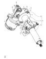
- FIG. 2 is a perspective view of the steering column of FIG. 1;
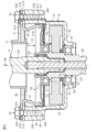
- FIG. 3 is a sectional view of a connecting portion between the housing and the lower tube in FIG. 2;
- FIG. 4 is a perspective view of the bearing support member of FIG. 3 viewed diagonally from above.
- FIG. 4 is a perspective view of the bearing support member of FIG. 3 viewed diagonally from below.
- 4 is a half-sectional view of the bearing support member of FIG. 3.
- FIG. 4 is a half-sectional view of the bearing support member of FIG. 3.
- FIG. 7 is a sectional view of a housing according to a second embodiment.
- the steering device 1 includes a steering shaft 2, an intermediate shaft 3, a pinion shaft 4, and a rack shaft 5.
- a steering wheel 6 is connected to a first end of the steering shaft 2.
- a first end of an intermediate shaft 3 is connected to a second end of the steering shaft 2 via a universal joint 7.
- a first end of a pinion shaft 4 is connected to a second end of the intermediate shaft 3 via a universal joint 8.
- a pinion 4a is provided at the second end of the pinion shaft 4.
- the pinion 4a meshes with a rack 5a provided on the rack shaft 5.
- the rack shaft 5 is supported inside a housing 10 fixed to a frame 9 of the vehicle body.
- the rack shaft 5 is movable leftward or rightward with respect to the traveling direction of the vehicle. Both ends of the rack shaft 5 are connected to left and right steered wheels (not shown) via tie rods (not shown).
- the steering shaft 2 has an outer shaft 11 and an inner shaft 12.
- the outer shaft 11 and the inner shaft 12 are connected to each other by, for example, a spline connection.
- the outer shaft 11 and the inner shaft 12 are rotatable together and movable relative to each other along the axial direction.
- the steering shaft 2 is provided obliquely with respect to the longitudinal direction of the vehicle with the steering wheel 6 facing upward.
- the steering device 1 has a steering column 15.
- the steering shaft 2 is inserted through the steering column 15.
- Steering shaft 2 is rotatably supported by steering column 15 via a bearing (not shown).
- the steering column 15 is attached to two frames 13 and 14 provided on the vehicle body.
- One frame 13 is located more rearward than the other frame 14 in the longitudinal direction of the vehicle.
- the steering column 15 has an upper tube 16, a lower tube 17, and a housing 18.
- Upper tube 16 is cylindrical.
- the lower tube 17 is cylindrical and has a flange 31.
- Upper tube 16 and lower tube 17 are fitted into each other.
- the upper tube 16 is inserted into the first end of the lower tube 17.
- the first end is the end opposite to the second end where the flange 31 is provided.
- the upper tube 16 and the lower tube 17 are movable relative to each other in the axial direction of the steering shaft 2.
- the lower tube 17 has a column bracket 17A.
- the lower tube 17 is attached to the frame 13 of the vehicle body via a column bracket 17A.
- the upper tube 16 and the lower tube 17 are made of, for example, a magnetic material.
- the magnetic material includes magnetic metals such as iron.
- the upper tube 16 and the lower tube 17 constitute a support tube that rotatably supports the steering shaft 2.
- the housing 18 is connected to the second end of the lower tube 17.
- the housing 18 has two support parts 18A (only one is shown in FIG. 1) and a support shaft 18B.
- the two support parts 18A are provided on the side surface of the housing 18 opposite to the lower tube 17.
- the two support parts 18A face each other in the width direction of the vehicle body.
- the support shaft 18B extends between the two support parts 18A.
- the support shaft 18B is rotatably connected to a bracket 24 fixed to the frame 14 of the vehicle body.
- a motor 19 for assisting steering is provided outside the housing 18.
- a reduction gear 20 is housed inside the housing 18 .
- the reducer 20 reduces the rotation of the motor 19 and transmits the reduced rotation to the inner shaft 12 .
- the reducer 20 is a worm reducer having a worm 21 and a worm wheel 22.
- the worm 21 is connected to an output shaft (not shown) of the motor 19 so as to be integrally rotatable therewith.
- the axis of the worm 21 and the axis of the output shaft of the motor 19 are located on the same straight line.
- the worm wheel 22 meshes with the worm 21.
- the worm wheel 22 is provided to be rotatable integrally with the inner shaft 12.
- the axis of the worm wheel 22 and the axis of the inner shaft 12 are located on the same straight line.
- the steering device 1 has a lock mechanism (not shown).
- the locking mechanism selectively locks and unlocks the swinging of the steering column 15 about the support shaft 18B and the expansion and contraction of the steering column 15 through the operation of a lever (not shown).
- the steering column 15 can swing relative to the column bracket 17A about the support shaft 18B.
- the vertical position of the steering wheel 6 can be adjusted by moving the steering wheel 6 upward or downward.
- the upper tube 16 can be moved in the axial direction of the steering shaft 2 with respect to the lower tube 17. After unlocking the lever, by moving the steering wheel 6 in the axial direction of the steering shaft 2, it is possible to adjust the position of the steering wheel 6 in the axial direction.
- the lower tube 17 has a flange 31.
- the flange 31 is provided at the second end of the lower tube 17.
- the second end of the lower tube 17 is the end opposite to the first end into which the upper tube 16 is inserted.
- the flange 31 is an annular flat plate.
- the flange 31 has two attachment parts 31A.
- the two attachment parts 31A are provided on the outer peripheral surface of the flange 31.
- the two attachment portions 31A protrude radially outward from the outer peripheral surface of the flange 31.
- the two attachment parts 31A are located on opposite sides of the flange 31 in the radial direction.
- the two attachment parts 31A each have an insertion hole 31B.
- the bolt 30 is inserted into the insertion hole 31B. By tightening this bolt 30 to the housing 18, the flange 31 is fixed to the housing 18.
- the bolt 30 has a head 30A and a shaft portion 30B.
- the housing 18 includes a worm wheel housing member 41 and a worm housing member 42.
- Worm wheel housing member 41 and worm housing member 42 each have a cylindrical shape.
- the worm housing member 42 is connected to the outer peripheral surface of the worm wheel housing member 41.
- the worm housing member 42 extends in a direction perpendicular to the axis of the worm wheel housing member 41.
- the inside of the worm wheel housing member 41 and the inside of the worm housing member 42 communicate with each other via a communication hole (not shown).
- Worm wheel housing member 41 constitutes a cylindrical portion of housing 18 .
- the housing 18 is made of, for example, a non-magnetic material. Nonmagnetic materials include nonmagnetic metals such as aluminum.
- the worm wheel 22 is rotatably housed inside the worm wheel housing member 41.
- the worm 21 is rotatably supported inside the worm housing member 42 via a bearing (not shown).
- the worm wheel 22 and the worm 21 engage with each other through the communication hole provided inside the housing 18.
- the worm wheel 22 and the worm 21 are made of, for example, a magnetic material.
- the magnetic material includes magnetic metals such as iron.
- the worm wheel housing member 41 has an opening 41A at a first end in the axial direction, and an end wall at a second end opposite to the first end. are doing.
- the opening 41A opens toward the lower tube 17 along the axis of the worm wheel housing member 41.
- the outer diameter of the worm wheel housing member 41 is substantially the same as the outer diameter of the flange 31.
- the worm wheel housing member 41 has a cylindrical bearing support portion 43.
- the bearing support portion 43 is provided on the end wall of the worm wheel housing member 41.
- the opening portion 41A and the bearing support portion 43 are arranged coaxially.
- the inside of the worm wheel housing member 41 and the outside of the worm wheel housing member 41 communicate with each other via the bearing support portion 43.
- the worm wheel housing member 41 has two tightening parts 44.
- Each tightening portion 44 is a portion where the bolt 30 is tightened when fixing the flange 31 to the housing 18.
- Each tightening portion 44 protrudes radially outward from the outer peripheral surface of the worm wheel housing member 41.
- the two tightening portions 44 are located on opposite sides of the worm wheel housing member 41 in the radial direction.
- Each tightening portion 44 has a screw hole 44A. The end surface of each tightening portion 44 in which the screw hole 44A opens is flush with the end surface of the worm wheel housing member 41 in which the opening 41A opens.
- the peripheral edge of the flange 31 is in contact with the end surface of the worm wheel housing member 41 where the opening 41A opens.
- the insertion hole 31B of the flange 31 and the screw hole 44A of the housing 18 are aligned with each other.
- the bolt 30 is inserted into the insertion hole 31B of the flange 31 from the side opposite to the housing 18. This bolt 30 is tightened to a tightening portion 44 of the housing 18.
- the flange 31 is fixed to the housing 18. That is, the lower tube 17 is connected to the housing 18 via the flange 31. Further, the opening 41A of the housing 18 is closed by the flange 31.
- the flange 31 also serves as a cover that closes the opening 41A of the housing 18.
- the worm wheel housing member 41 rotatably supports the inner shaft 12.
- the inner shaft 12 passes through the worm wheel housing member 41.
- the axis of the inner shaft 12 and the axis of the worm wheel housing member 41 are located on the same straight line.
- the inner shaft 12 has an input shaft 12A, an output shaft 12B, and a torsion bar 12C.
- the input shaft 12A and the output shaft 12B are connected to each other via a torsion bar 12C.
- the output shaft 12B is a hollow cylinder.
- a first end of the input shaft 12A is connected to the outer shaft 11.
- the second end of the input shaft 12A is inserted into the first end of the output shaft 12B.
- a gap exists between the outer peripheral surface of the input shaft 12A and the inner peripheral surface of the output shaft 12B.
- a sliding bearing 12D is interposed between the outer peripheral surface of the input shaft 12A and the inner peripheral surface of the output shaft 12B. The input shaft 12A and the output shaft 12B can rotate relative to each other via a sliding bearing 12D.
- the first end of the torsion bar 12C is inserted and fixed to the second end of the input shaft 12A.
- a second end of the torsion bar 12C is inserted into the output shaft 12B.
- a second end of the torsion bar 12C is fixed to a second end of the output shaft 12B.
- Steering torque applied to the steering wheel 6 is transmitted to the output shaft 12B via the input shaft 12A and torsion bar 12C.
- the torsion bar 12C twists according to the steering torque.
- the worm wheel 22 and the bearing support member 50 are housed inside the worm wheel housing member 41.
- the worm wheel 22 is fixed to the outer peripheral surface of the output shaft 12B so as to be integrally rotatable therewith.
- the bearing support member 50 has a cylindrical shape and is mounted so as to be rotatable relative to the outer peripheral surface of the output shaft 12B.
- the worm wheel 22 and the bearing support member 50 are arranged along the axial direction of the worm wheel housing member 41 at intervals.
- the worm wheel 22 is arranged between the bearing support member 50 and the end wall of the worm wheel housing member 41.
- the worm wheel housing member 41, the worm wheel 22, and the bearing support member 50 are arranged coaxially.
- the bearing support member 50 has a cylindrical inner circumferential wall 51, a cylindrical outer circumferential wall 52, and an annular connecting wall 53.
- the inner circumferential wall 51 is located on the radially inner side of the outer circumferential wall 52.
- the axial position of the inner peripheral wall 51 and the axial position of the outer peripheral wall 52 are slightly different.
- the connecting wall 53 is a wall portion of the bearing support member 50 that extends in the radial direction.
- the connecting wall 53 connects the base end of the inner peripheral wall 51 and the base end of the outer peripheral wall 52.
- the tip of the inner peripheral wall 51 and the tip of the outer peripheral wall 52 face opposite to each other in the axial direction.
- the distal end is the end opposite to the proximal end.
- the connecting wall 53 has an inner flat part 53A, an inclined part 53B, and an outer flat part 53C. With the inner peripheral wall 51 as a reference, the inner flat portion 53A, the inclined portion 53B, and the outer flat portion 53C are connected in this order. The inner flat portion 53A and the outer flat portion 53C extend in a direction perpendicular to the axial direction. An inner circumferential portion of the inner flat portion 53A is connected to a base end portion of the inner circumferential wall 51. An outer peripheral portion of the outer flat portion 53C is connected to a base end portion of the outer peripheral wall 52.
- the outer flat portion 53C is disposed at a position shifted toward the tip end of the inner peripheral wall 51 in the axial direction of the bearing support member 50 with respect to the inner flat portion 53A.
- the inclined portion 53B is inclined such that the radially outer portion of the connecting wall 53 approaches the tip of the inner peripheral wall 51 in the axial direction of the bearing support member 50.
- the inner diameter of the inner peripheral wall 51 is set to be slightly shorter than the outer diameter of the bearing 71.
- the outer diameter of the outer peripheral wall 52 is set to be slightly longer than the inner diameter of the worm wheel housing member 41.
- the inner diameter of the inner circumferential wall 51 and the outer diameter of the outer circumferential wall 52 are determined according to the determined press-fitting allowance.
- the bearing support member 50 is formed by bending a single plate.
- the bearing support member 50 is made of, for example, a magnetic material.
- the magnetic material includes magnetic metals such as iron.
- the bearing support member 50 is formed, for example, by plastically deforming a single metal plate punched into a predetermined shape using a press.
- the inner circumferential surface of the bearing support member 50 fits into the outer circumferential surface of the bearing 71.
- the outer circumferential surface of the bearing support member 50 that is, the outer circumferential surface of the outer circumferential wall 52, fits into the inner circumferential surface of the worm wheel housing member 41.
- the bearing support member 50 is press-fitted into the inner peripheral surface of the worm wheel housing member 41 from the mounting direction DW.
- the mounting direction DW is a direction along the axis of the worm wheel housing member 41, and is a direction in which the bearing support member 50 is inserted into the worm wheel housing member 41.
- the axial position of the bearing support member 50 with respect to the worm wheel housing member 41 is determined by managing the press-fitting stroke of a press-fitting device (not shown).
- the inner peripheral wall 51 extends from the connecting wall 53 in the same direction as the mounting direction DW.
- the outer peripheral wall 52 extends from the connecting wall 53 in a direction opposite to the mounting direction DW.
- the tip of the inner circumferential wall 51 faces in the same direction as the mounting direction DW.
- the tip of the outer peripheral wall 52 faces in the opposite direction to the mounting direction DW.
- the base end of the outer peripheral wall 52 is disposed at a position shifted from the base end of the inner peripheral wall 51 in the mounting direction DW.
- the inclined portion 53B is inclined such that the radially outer portion thereof is displaced in the mounting direction DW.
- the output shaft 12B is rotatably supported on the inner circumferential surface of the bearing support portion 43 via the bearing 61.
- the bearing 61 is in a state in which movement in the axial direction is restricted.
- An annular step portion 62 and a retaining ring 63 are provided on the outer peripheral surface of the output shaft 12B.
- the inner ring of the bearing 61 is interposed between the stepped portion 62 and the retaining ring 63.
- An annular protrusion 64 and a retaining ring 65 are provided on the inner circumferential surface of the bearing support portion 43 .
- the outer ring of the bearing 61 is interposed between the protrusion 64 and the retaining ring 65.
- the output shaft 12B is rotatably supported by the inner circumferential wall 51 of the bearing support member 50 via a bearing 71.
- the bearing 71 is in a state in which movement in the axial direction is restricted.
- An annular protrusion 72 is provided on the outer peripheral surface of the output shaft 12B.
- a cylindrical nut member (not shown) is attached to the first end of the output shaft 12B.
- the inner ring of the bearing 71 is interposed between the protrusion 72 and the nut member.
- the outer ring of the bearing 71 is maintained in a state where it is elastically pressed radially inward by the inner circumferential wall 51.
- the outer ring of the bearing 71 is supported by the inner peripheral wall 51.
- the internal space of the worm wheel housing member 41 is divided into two spaces by the bearing support member 50.
- a sensor 80 is provided in the space between the bearing support member 50 and the flange 31.
- Sensor 80 includes a torque sensor and a rotation angle sensor.
- the torque sensor detects steering torque based on the amount of twist of the torsion bar 12C.
- the rotation angle sensor detects the rotation angle of the input shaft 12A as a steering angle.
- Grease is sealed in the space between the bearing support member 50 and the end wall of the worm wheel housing member 41.
- the first embodiment has the following functions and effects.
- (1-1) As shown in FIG. 6, the bearing support member 50 is mounted on the worm wheel housing member 41 with the outer peripheral wall 52 facing in the opposite direction to the mounting direction DW.
- the bearing support member 50 When the bearing support member 50 is press-fitted into the worm wheel housing member 41 , the outer circumferential surface of the outer circumferential wall 52 slides against the inner circumferential surface of the worm wheel housing member 41 . At this time, sliding resistance acts on the outer peripheral wall 52 in a direction opposite to the mounting direction DW.
- the connecting wall 53 is slightly elastically deformed using the connecting portion between the inner circumferential wall 51 and the inner flat portion 53A as a fulcrum so as to be inclined in a direction opposite to the mounting direction DW. Accordingly, the tip end of the outer circumferential wall 52 inclines inward in the radial direction, so that the outer diameter of the tip end of the outer circumferential wall 52 is slightly reduced.
- the contact area between the outer peripheral surface of the outer peripheral wall 52 and the worm wheel housing member 41 is reduced. Further, by reducing the contact area, the sliding resistance between the outer peripheral wall 52 and the worm wheel housing member 41 is reduced. Since it becomes easier to insert the bearing support member 50 into the inside of the worm wheel housing member 41, ease of assembly is improved. Moreover, the press-fitting load can be reduced.
- the press-fitting load is the force required to press-fit the bearing support member 50 into the worm wheel housing member 41. Therefore, it is possible to obtain a novel steering device 1 in which the bearing support member 50 can be easily press-fitted into the worm wheel housing member 41.
- the reverse input load F is a force in the opposite direction to the mounting direction DW.
- the reverse input load F is transmitted to the inner circumferential wall 51 of the bearing support member 50 via the output shaft 12B and the bearing 71.
- a force acts on the connecting wall 53 to tilt the connecting wall 53 in the same direction as the mounting direction DW, using the connecting portion between the inner circumferential wall 51 and the inner flat portion 53A as a fulcrum.
- a force acts on the outer circumferential wall 52 to incline the distal end of the outer circumferential wall 52 radially outward so that the outer diameter of the distal end of the outer circumferential wall 52 increases.
- the outer circumferential surface of the outer circumferential wall 52 is more strongly pressed radially outward against the inner circumferential surface of the worm wheel housing member 41.
- the pull-out load is a force required to move the bearing support member 50 press-fitted into the worm wheel housing member 41 in a direction opposite to the mounting direction DW. Therefore, as the pull-out load increases, movement of the bearing support member 50 in the direction opposite to the mounting direction DW is suppressed.
- the outer peripheral wall 52 so as to face the same direction as the mounting direction DW.
- the connecting wall 53 is slightly tilted in the same direction as the mounting direction DW, using the connecting portion between the inner circumferential wall 51 and the inner flat portion 53A as a fulcrum. Deforms elastically. Accordingly, the tip end of the outer circumferential wall 52 inclines inward in the radial direction, so that the outer diameter of the tip end of the outer circumferential wall 52 is slightly reduced.
- the outer peripheral wall 52 is provided so as to face in the opposite direction to the mounting direction DW.
- the bearing support member 50 is maintained press-fitted into the inner peripheral surface of the worm wheel housing member 41. Therefore, there is no need to provide a separate member for maintaining the axial position of the bearing support member 50. Further, fastening parts such as bolts for fixing the bearing support member 50 to the worm wheel housing member 41 are not necessary. Therefore, an increase in the number of parts of the steering device 1 can be suppressed. Moreover, the product cost of the steering device 1 can be reduced.
- the bearing support member 50 is maintained press-fitted into the inner peripheral surface of the worm wheel housing member 41.
- the inner circumferential surface of the inner circumferential wall 51 is maintained in a state where it is elastically pressed radially inward against the outer circumferential surface of the outer ring of the bearing 71.
- no gap exists between the inner circumferential surface of the inner circumferential wall 51 and the outer circumferential surface of the outer ring of the bearing 71. Therefore, it is difficult for the grease to pass through the boundary between the inner circumferential surface of the inner circumferential wall 51 and the outer circumferential surface of the outer ring of the bearing 71. Therefore, grease is prevented from leaking from the first space between the bearing support member 50 and the end wall of the worm wheel housing member 41 to the second space between the bearing support member 50 and the flange 31. Ru.
- the outer circumferential surface of the outer circumferential wall 52 is maintained in a state where it is elastically pressed radially outward against the inner circumferential surface of the worm wheel housing member 41.
- the connecting wall 53 has an inclined portion 53B. By adjusting the degree of inclination of the inclined portion 53B, the load deflection characteristics of the connecting wall 53 can be adjusted.
- the load deflection characteristic is the relationship between the load acting on a part and the amount of deflection of the part in response to that load.
- the bearing support member 50 is formed by bending a single plate.
- the plate material is, for example, a magnetic metal plate material. Therefore, the bearing support member 50 can be easily formed by pressing or the like. Furthermore, the weight of the bearing support member 50 can be reduced.
- the bearing support member 50 is made of metal. Therefore, for example, when the bearing support member 50 is attached to the worm wheel housing member 41, damage to the bearing support member 50 can be suppressed.
- the sensor 80 includes a magnetic torque sensor.
- the torque sensor has a permanent magnet fixed to the input shaft 12A and a yoke unit fixed to the output shaft 12B.
- the yoke unit is made up of two yokes integrated through a resin part.
- the torque sensor detects the torque applied to the torsion bar 12C based on a change in the magnetic flux of the yoke due to a change in the relative position between the permanent magnet and the yoke.
- a permanent magnet and two yokes form a magnetic circuit.
- the first magnetic flux path R1 is a path including the upper tube 16, the lower tube 17, and the sensor 80. In this case, there is a concern that the torque detection accuracy of the sensor 80 may decrease due to the sensor 80 being affected by the magnetic field from the magnetic field source. Therefore, in this embodiment, the following configuration is adopted as the steering device 1.
- the steering device 1 has two magnetic path members 81.
- the magnetic path member 81 is for connecting the flange 31 and the outer peripheral wall 51 of the bearing support member 50.
- the magnetic path member 81 is made of magnetic metal.
- the magnetic path member 81 is formed by bending a single metal plate.
- the magnetic path member 81 is formed, for example, by plastically deforming a single metal plate punched into a predetermined shape using a press.
- the magnetic path member 81 has a first magnetic path section 81A and a second magnetic path section 81B.
- the first magnetic path portion 81A extends in the radial direction of the worm wheel housing member 41.
- the first magnetic path portion 81A has a flat plate shape and is sandwiched between the tightening portion 44 of the worm wheel housing member 41 and the attachment portion 31A of the flange 31.
- the first magnetic path portion 81A is axially fastened together with the mounting portion 31A and the tightening portion 44 by bolts 30.
- a portion of the first end in the radial direction of the first magnetic path portion 81A may be exposed to the outside of the housing 18.
- a second end of the first magnetic path section 81A in the radial direction is located inside the housing 18.
- the second magnetic path portion 81B is inclined so as to approach the inner peripheral surface of the worm wheel housing member 41 as it goes in the mounting direction DW of the bearing support member 50.
- a first end of the second magnetic path section 81B is connected to a second end of the first magnetic path section 81A.
- the connecting portion between the first magnetic path section 81A and the second magnetic path section B is smoothly curved.
- the second end of the second magnetic path portion 81B is curved inward in the radial direction of the worm wheel housing member 41.
- the curved convex portion of the second end functions as a contact portion 81C with respect to the bearing support member 50.
- the contact portion 81C is maintained in a state where it is elastically pressed radially outward against the inner circumferential surface of the outer circumferential wall 52.
- the distance between the bearing support member 50 and the worm wheel 22 in the axial direction is set to a distance that allows the magnetic flux from the assumed magnetic field generation source to pass through.
- the upper tube 16, the lower tube 17, the flange 31, the magnetic path member 81, the bearing support member 50, and the worm wheel 22 are all made of magnetic metal. Therefore, the upper tube 16, the lower tube 17, the flange 31, the magnetic path member 81, the bearing support member 50, and the worm wheel 22 can be magnetically coupled to each other to form the second magnetic flux path R2. is possible.
- the second magnetic flux path R2 is a magnetic flux path that detours around the sensor 80.
- the flange 31 and the magnetic member of the sensor 80 are separated from each other in the axial direction. That is, the magnetic resistance between the flange 31 and the first magnetic path section 81A is smaller than the magnetic resistance between the flange 31 and the magnetic member of the sensor 80.
- the magnetic members are a permanent magnet and a yoke. Therefore, the magnetic flux applied from the outside of the steering device 1 flows more easily into the first magnetic path portion 81A than into the magnetic member of the sensor 80.
- the axial distance between the tip of the inner peripheral wall 51 of the bearing support member 50 and the worm wheel 22 is shorter than the axial distance between the flange 31 and the magnetic member of the sensor 80. Further, the axial distance between the tip of the inner circumferential wall 51 of the bearing support member 50 and the worm wheel 22 is shorter than the axial distance between the magnetic member of the sensor 80 and the worm wheel 22. Therefore, in total, the magnetic resistance of the second magnetic flux path R2 is smaller than the magnetic resistance of the first magnetic flux path R1.
- a slight gap may exist between the flange 31 and the first magnetic path portion 81A. However, the gap is shorter than the axial distance between the flange 31 and the magnetic member of the sensor 80. Furthermore, a slight gap may exist between the contact portion 81C and the inner circumferential surface of the outer circumferential wall 52. However, the gap is a gap that allows the magnetic flux from the assumed magnetic field generation source to pass through.
- the magnetic resistance of the second magnetic flux path R2 not including the sensor 80 is smaller than the magnetic resistance of the first magnetic flux path R1 including the sensor 80. Therefore, the magnetic flux applied from the outside of the steering device 1 passes not through the first magnetic flux path R1 including the sensor 80 but through the second magnetic flux path R2 that detours around the outside of the sensor 80 in the radial direction. By suppressing the magnetic flux from the magnetic field generation source being applied to the sensor 80, the detection accuracy of the sensor 80 can be ensured.
- the bearing support member 50 is formed of a non-magnetic material such as synthetic resin, it is difficult to form the second magnetic flux path R2 that detours around the outside of the sensor 80 in the radial direction. In this case, there is a high probability that the magnetic flux from the magnetic field generation source passes through the first magnetic flux path R1 that includes the sensor 80.
- a second magnetic flux path R2 that bypasses the sensor 80 is formed using magnetic members such as the flange 31, the bearing support member 50, and the worm wheel 22. It is only necessary to provide a magnetic path member 81 for magnetically coupling the flange 31 and the bearing support member 50. Therefore, product cost can be reduced compared to, for example, a case where a magnetic shield is provided surrounding the sensor 80. Since the processing of the magnetic shield is complicated, there is a risk that the product cost will increase. According to the present embodiment, the magnetic shielding function that blocks the influence of external magnetic fields on the sensor 80 is provided to the steering device 1 by magnetically coupling magnetic components present around the sensor 80. You can have it.
- first and second embodiments may be modified and implemented as follows.
- the bearing support member 50 and the housing 18 may be made of synthetic resin. Synthetic resin materials are cheaper than metal materials. Therefore, the product cost of the steering device 1 can be reduced.
- the inclined portion 53B of the connecting wall 53 may be omitted.
- the connecting wall 53 is a radially extending flat wall.
- only one magnetic path member 81 may be provided.
- three or more magnetic path members 81 may be provided.
- the magnetic path member 81 may be omitted depending on the product specifications.
- the axial distance between the flange 31 and the outer peripheral wall 52 is shortened to such an extent that the flange 31 and the outer peripheral wall 52 can be magnetically coupled.
- the outer peripheral wall 52 may be extended in a direction opposite to the mounting direction DW.
- the degree to which magnetic coupling is possible is the degree to which the magnetic flux from the magnetic flux generation source can pass from the flange 31 to the outer peripheral wall 52.
- the housing 18 when the magnetic path member 81 is omitted, the housing 18 may be formed of magnetic metal.
- the magnetic flux from the magnetic flux source passes through, for example, the flange 31, the worm wheel housing member 41, and the bearing support member 50 in this order.
- the second magnetic flux path R2 may include a component that contacts the output shaft 12B.
- the bearing 71 may constitute a part of the second magnetic flux path R2.
- the steering device 1 with a structure for adjusting the vertical position of the steering wheel 6 and a structure for adjusting the position of the steering wheel 6 in the axial direction.
- a single support tube that does not expand or contract is provided in place of the upper tube 16 and lower tube 17, a single support tube that does not expand or contract is provided.
- the steering shaft 2 is rotatably supported by this single support tube.
- the housing 18 is fixed to the frame 14 of the vehicle body. A configuration in which the support portion 18A and the support shaft 18B are omitted from the housing 18 can be adopted. Furthermore, a locking mechanism that selectively locks and unlocks the swinging of the steering column 15 about the support shaft 18B and the expansion and contraction of the steering column 15 is also unnecessary.
- the steering device 1 may be a steer-by-wire type steering device. In this case, power transmission between the steering wheel 6 and the steered wheels is separated.
- Motor 19 functions as a reaction motor.
- the reaction motor generates a steering reaction torque that is applied to the steering shaft 2 of the vehicle.
- the steering reaction torque is a torque in a direction opposite to the steering direction of the steering wheel 6.
Landscapes
- Engineering & Computer Science (AREA)
- Mechanical Engineering (AREA)
- General Engineering & Computer Science (AREA)
- Chemical & Material Sciences (AREA)
- Combustion & Propulsion (AREA)
- Transportation (AREA)
- Power Steering Mechanism (AREA)
Priority Applications (5)
| Application Number | Priority Date | Filing Date | Title |
|---|---|---|---|
| EP22930162.7A EP4491491A4 (en) | 2022-03-11 | 2022-03-11 | STEERING DEVICE |
| CN202280093310.5A CN118900802B (zh) | 2022-03-11 | 2022-03-11 | 转向装置 |
| US18/843,854 US20250091638A1 (en) | 2022-03-11 | 2022-03-11 | Steering device |
| JP2024505838A JP7790549B2 (ja) | 2022-03-11 | 2022-03-11 | ステアリング装置 |
| PCT/JP2022/011022 WO2023170957A1 (ja) | 2022-03-11 | 2022-03-11 | ステアリング装置 |
Applications Claiming Priority (1)
| Application Number | Priority Date | Filing Date | Title |
|---|---|---|---|
| PCT/JP2022/011022 WO2023170957A1 (ja) | 2022-03-11 | 2022-03-11 | ステアリング装置 |
Publications (1)
| Publication Number | Publication Date |
|---|---|
| WO2023170957A1 true WO2023170957A1 (ja) | 2023-09-14 |
Family
ID=87936469
Family Applications (1)
| Application Number | Title | Priority Date | Filing Date |
|---|---|---|---|
| PCT/JP2022/011022 Ceased WO2023170957A1 (ja) | 2022-03-11 | 2022-03-11 | ステアリング装置 |
Country Status (5)
| Country | Link |
|---|---|
| US (1) | US20250091638A1 (https=) |
| EP (1) | EP4491491A4 (https=) |
| JP (1) | JP7790549B2 (https=) |
| CN (1) | CN118900802B (https=) |
| WO (1) | WO2023170957A1 (https=) |
Cited By (1)
| Publication number | Priority date | Publication date | Assignee | Title |
|---|---|---|---|---|
| WO2025186868A1 (ja) * | 2024-03-04 | 2025-09-12 | 株式会社ジェイテクト | 操舵装置 |
Citations (4)
| Publication number | Priority date | Publication date | Assignee | Title |
|---|---|---|---|---|
| WO2004040734A1 (ja) * | 2002-10-31 | 2004-05-13 | Nsk Ltd. | 電動パワーステアリング装置 |
| WO2014069423A1 (ja) * | 2012-10-29 | 2014-05-08 | 日本精工株式会社 | 電動式パワーステアリング装置 |
| JP2018520926A (ja) | 2015-05-07 | 2018-08-02 | ローベルト ボッシュ オートモーティブ ステアリング ゲゼルシャフト ミット ベシュレンクテル ハフツングRobert Bosch Automotive Steering GmbH | ステアリングシャフトを支持するための軸受ユニット |
| WO2019059230A1 (ja) * | 2017-09-20 | 2019-03-28 | 日本精工株式会社 | トルクセンサ及びステアリング装置 |
Family Cites Families (7)
| Publication number | Priority date | Publication date | Assignee | Title |
|---|---|---|---|---|
| US6000490A (en) * | 1997-12-17 | 1999-12-14 | Deere & Company | Steering input device |
| JP2008254495A (ja) * | 2007-04-02 | 2008-10-23 | Jtekt Corp | 電動パワーステアリング装置 |
| JP5158415B2 (ja) * | 2007-12-17 | 2013-03-06 | 株式会社ジェイテクト | 電動パワーステアリング装置 |
| JP2011080870A (ja) * | 2009-10-07 | 2011-04-21 | Jtekt Corp | トルクセンサ及び電動パワーステアリング装置 |
| EP2921372A4 (en) * | 2012-11-15 | 2016-11-02 | Nsk Ltd | ELECTRIC POWER STEERING SYSTEM |
| JP2014237340A (ja) * | 2013-06-06 | 2014-12-18 | 株式会社ジェイテクト | 電動パワーステアリング装置 |
| CN109955890A (zh) * | 2017-12-26 | 2019-07-02 | 长城汽车股份有限公司 | 转向机构及车辆 |
-
2022
- 2022-03-11 JP JP2024505838A patent/JP7790549B2/ja active Active
- 2022-03-11 CN CN202280093310.5A patent/CN118900802B/zh active Active
- 2022-03-11 EP EP22930162.7A patent/EP4491491A4/en active Pending
- 2022-03-11 US US18/843,854 patent/US20250091638A1/en active Pending
- 2022-03-11 WO PCT/JP2022/011022 patent/WO2023170957A1/ja not_active Ceased
Patent Citations (4)
| Publication number | Priority date | Publication date | Assignee | Title |
|---|---|---|---|---|
| WO2004040734A1 (ja) * | 2002-10-31 | 2004-05-13 | Nsk Ltd. | 電動パワーステアリング装置 |
| WO2014069423A1 (ja) * | 2012-10-29 | 2014-05-08 | 日本精工株式会社 | 電動式パワーステアリング装置 |
| JP2018520926A (ja) | 2015-05-07 | 2018-08-02 | ローベルト ボッシュ オートモーティブ ステアリング ゲゼルシャフト ミット ベシュレンクテル ハフツングRobert Bosch Automotive Steering GmbH | ステアリングシャフトを支持するための軸受ユニット |
| WO2019059230A1 (ja) * | 2017-09-20 | 2019-03-28 | 日本精工株式会社 | トルクセンサ及びステアリング装置 |
Non-Patent Citations (1)
| Title |
|---|
| See also references of EP4491491A4 |
Cited By (1)
| Publication number | Priority date | Publication date | Assignee | Title |
|---|---|---|---|---|
| WO2025186868A1 (ja) * | 2024-03-04 | 2025-09-12 | 株式会社ジェイテクト | 操舵装置 |
Also Published As
| Publication number | Publication date |
|---|---|
| EP4491491A1 (en) | 2025-01-15 |
| JP7790549B2 (ja) | 2025-12-23 |
| US20250091638A1 (en) | 2025-03-20 |
| EP4491491A4 (en) | 2025-05-14 |
| CN118900802A (zh) | 2024-11-05 |
| CN118900802B (zh) | 2026-04-10 |
| JPWO2023170957A1 (https=) | 2023-09-14 |
Similar Documents
| Publication | Publication Date | Title |
|---|---|---|
| US6705176B2 (en) | Electric power steering apparatus | |
| JP4989707B2 (ja) | 電動式動力補助操向装置の減速機 | |
| KR100607474B1 (ko) | 전동 파워 스티어링 장치 | |
| CN115103792B (zh) | 车辆的转向柱 | |
| US20060117889A1 (en) | Worm speed reducer and electric power steering device | |
| JP4979801B2 (ja) | ウォーム減速機及び電動式パワーステアリング装置 | |
| EP2832626B1 (en) | Electric power steering device | |
| KR102885510B1 (ko) | 스티어 바이 와이어식 조향장치 | |
| CA2675795C (en) | Power steering device | |
| JP2003072566A (ja) | 盗難防止機能を備えた電動パワーステアリング装置とその製造方法 | |
| KR20180089629A (ko) | 전동식 동력 보조 조향장치의 감속기 | |
| EP1985521B1 (en) | Energy absorbing steering system | |
| WO2004004992A1 (ja) | 電動パワーステアリング装置 | |
| WO2023170957A1 (ja) | ステアリング装置 | |
| US20130298718A1 (en) | Steering device | |
| US20080277193A1 (en) | Electric power steering device | |
| KR101452545B1 (ko) | 전동식 동력 보조 조향장치의 감속기 | |
| JP2000318626A (ja) | 電動式パワーステアリング装置 | |
| US8336412B1 (en) | Electric power steering apparatus | |
| JP7779935B2 (ja) | 回転制限装置およびステアリング装置 | |
| JP2024093325A (ja) | ステアリング装置 | |
| JP4000781B2 (ja) | ステアリング装置 | |
| JP4454799B2 (ja) | 電動パワーステアリング装置 | |
| JP2002067986A (ja) | ステアリング装置 | |
| JP4454800B2 (ja) | 電動パワーステアリング装置 |
Legal Events
| Date | Code | Title | Description |
|---|---|---|---|
| 121 | Ep: the epo has been informed by wipo that ep was designated in this application |
Ref document number: 22930162 Country of ref document: EP Kind code of ref document: A1 |
|
| ENP | Entry into the national phase |
Ref document number: 2024505838 Country of ref document: JP Kind code of ref document: A |
|
| WWE | Wipo information: entry into national phase |
Ref document number: 18843854 Country of ref document: US |
|
| WWE | Wipo information: entry into national phase |
Ref document number: 202280093310.5 Country of ref document: CN |
|
| WWE | Wipo information: entry into national phase |
Ref document number: 2022930162 Country of ref document: EP |
|
| NENP | Non-entry into the national phase |
Ref country code: DE |
|
| ENP | Entry into the national phase |
Ref document number: 2022930162 Country of ref document: EP Effective date: 20241011 |
|
| WWP | Wipo information: published in national office |
Ref document number: 18843854 Country of ref document: US |