WO2023170957A1 - ステアリング装置 - Google Patents
ステアリング装置 Download PDFInfo
- Publication number
- WO2023170957A1 WO2023170957A1 PCT/JP2022/011022 JP2022011022W WO2023170957A1 WO 2023170957 A1 WO2023170957 A1 WO 2023170957A1 JP 2022011022 W JP2022011022 W JP 2022011022W WO 2023170957 A1 WO2023170957 A1 WO 2023170957A1
- Authority
- WO
- WIPO (PCT)
- Prior art keywords
- bearing support
- support member
- wall
- worm wheel
- flange
- Prior art date
Links
Images


Classifications
-
- B—PERFORMING OPERATIONS; TRANSPORTING
- B62—LAND VEHICLES FOR TRAVELLING OTHERWISE THAN ON RAILS
- B62D—MOTOR VEHICLES; TRAILERS
- B62D5/00—Power-assisted or power-driven steering
- B62D5/04—Power-assisted or power-driven steering electrical, e.g. using an electric servo-motor connected to, or forming part of, the steering gear
Definitions
- the present disclosure relates to a steering device.
- the steering device disclosed in Patent Document 1 includes a motor and a bearing unit.
- the steering shaft passes through the bearing unit in the axial direction.
- the bearing unit has a housing.
- the housing has a casing and a casing cover.
- the casing has an opening that opens in the axial direction.
- the casing cover is attached to the casing so as to close the opening of the casing.
- the housing houses the helical gear and the buffer disc.
- the helical gear is integrally rotatably connected to the steering shaft.
- the helical gear is driven by a motor.
- the helical gear is supported in the axial direction by both the first bearing and the second bearing.
- a first bearing is provided on the buffer disc.
- a second bearing is provided on the end wall of the casing. The end wall is the wall opposite the opening.
- the steering shaft is rotatably supported by the casing via a first bearing and a second bearing.
- the buffer disc is located between the helical gear and the casing cover in the axial direction.
- the buffer disk is attached to the outer peripheral surface of the steering shaft via the first bearing.
- the outer peripheral surface of the buffer disk is in contact with the inner peripheral surface of the casing.
- a portion of the casing cover is supported on the side surface of the buffer disc via a spring member.
- the spring member applies an axial elastic force to the buffer disc toward the helical gear. The elastic force of the spring member prevents the buffer disk from moving away from the helical gear.
- the buffer disk has the function of buffering impacts acting in the radial and axial directions of the steering shaft.
- a steering device includes: a cylindrical support tube that has a flange and rotatably supports a steering shaft; a speed reducer configured to apply torque to the steering shaft; and a speed reducer configured to apply torque to the steering shaft.
- a housing having a cylindrical portion that accommodates the machine, the cylindrical portion being coaxially connected to the flange; and a bearing support that is fitted onto the inner circumferential surface of the cylindrical portion from a mounting direction that is a direction along the axial direction.
- the bearing support member includes a bearing support member through which the steering shaft passes, and a bearing interposed between an outer peripheral surface of the steering shaft and an inner peripheral surface of the bearing support member.
- the bearing support member includes an inner circumferential wall that fits on the outer circumferential surface of the bearing, an outer circumferential wall that fits on the inner circumferential surface of the cylindrical portion, and a connecting wall that connects the inner circumferential wall and the outer circumferential wall in the radial direction. It has .
- the inner circumferential wall has a base end connected to the connecting wall, and extends from the connecting wall in the same direction as the mounting direction.
- the outer peripheral wall has a base end connected to the connecting wall, and extends from the connecting wall in a direction opposite to the mounting direction.
- FIG. 1 is a schematic diagram showing the configuration of a steering device according to a first embodiment.
- FIG. 2 is a perspective view of the steering column of FIG. 1;
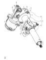
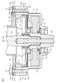
- FIG. 3 is a sectional view of a connecting portion between the housing and the lower tube in FIG. 2;
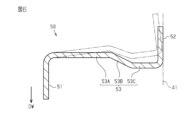
- FIG. 4 is a perspective view of the bearing support member of FIG. 3 viewed diagonally from above.
- FIG. 4 is a perspective view of the bearing support member of FIG. 3 viewed diagonally from below.
- 4 is a half-sectional view of the bearing support member of FIG. 3.
- FIG. 4 is a half-sectional view of the bearing support member of FIG. 3.
- FIG. 7 is a sectional view of a housing according to a second embodiment.
- the steering device 1 includes a steering shaft 2, an intermediate shaft 3, a pinion shaft 4, and a rack shaft 5.
- a steering wheel 6 is connected to a first end of the steering shaft 2.
- a first end of an intermediate shaft 3 is connected to a second end of the steering shaft 2 via a universal joint 7.
- a first end of a pinion shaft 4 is connected to a second end of the intermediate shaft 3 via a universal joint 8.
- a pinion 4a is provided at the second end of the pinion shaft 4.
- the pinion 4a meshes with a rack 5a provided on the rack shaft 5.
- the rack shaft 5 is supported inside a housing 10 fixed to a frame 9 of the vehicle body.
- the rack shaft 5 is movable leftward or rightward with respect to the traveling direction of the vehicle. Both ends of the rack shaft 5 are connected to left and right steered wheels (not shown) via tie rods (not shown).
- the steering shaft 2 has an outer shaft 11 and an inner shaft 12.
- the outer shaft 11 and the inner shaft 12 are connected to each other by, for example, a spline connection.
- the outer shaft 11 and the inner shaft 12 are rotatable together and movable relative to each other along the axial direction.
- the steering shaft 2 is provided obliquely with respect to the longitudinal direction of the vehicle with the steering wheel 6 facing upward.
- the steering device 1 has a steering column 15.
- the steering shaft 2 is inserted through the steering column 15.
- Steering shaft 2 is rotatably supported by steering column 15 via a bearing (not shown).
- the steering column 15 is attached to two frames 13 and 14 provided on the vehicle body.
- One frame 13 is located more rearward than the other frame 14 in the longitudinal direction of the vehicle.
- the steering column 15 has an upper tube 16, a lower tube 17, and a housing 18.
- Upper tube 16 is cylindrical.
- the lower tube 17 is cylindrical and has a flange 31.
- Upper tube 16 and lower tube 17 are fitted into each other.
- the upper tube 16 is inserted into the first end of the lower tube 17.
- the first end is the end opposite to the second end where the flange 31 is provided.
- the upper tube 16 and the lower tube 17 are movable relative to each other in the axial direction of the steering shaft 2.
- the lower tube 17 has a column bracket 17A.
- the lower tube 17 is attached to the frame 13 of the vehicle body via a column bracket 17A.
- the upper tube 16 and the lower tube 17 are made of, for example, a magnetic material.
- the magnetic material includes magnetic metals such as iron.
- the upper tube 16 and the lower tube 17 constitute a support tube that rotatably supports the steering shaft 2.
- the housing 18 is connected to the second end of the lower tube 17.
- the housing 18 has two support parts 18A (only one is shown in FIG. 1) and a support shaft 18B.
- the two support parts 18A are provided on the side surface of the housing 18 opposite to the lower tube 17.
- the two support parts 18A face each other in the width direction of the vehicle body.
- the support shaft 18B extends between the two support parts 18A.
- the support shaft 18B is rotatably connected to a bracket 24 fixed to the frame 14 of the vehicle body.
- a motor 19 for assisting steering is provided outside the housing 18.
- a reduction gear 20 is housed inside the housing 18 .
- the reducer 20 reduces the rotation of the motor 19 and transmits the reduced rotation to the inner shaft 12 .
- the reducer 20 is a worm reducer having a worm 21 and a worm wheel 22.
- the worm 21 is connected to an output shaft (not shown) of the motor 19 so as to be integrally rotatable therewith.
- the axis of the worm 21 and the axis of the output shaft of the motor 19 are located on the same straight line.
- the worm wheel 22 meshes with the worm 21.
- the worm wheel 22 is provided to be rotatable integrally with the inner shaft 12.
- the axis of the worm wheel 22 and the axis of the inner shaft 12 are located on the same straight line.
- the steering device 1 has a lock mechanism (not shown).
- the locking mechanism selectively locks and unlocks the swinging of the steering column 15 about the support shaft 18B and the expansion and contraction of the steering column 15 through the operation of a lever (not shown).
- the steering column 15 can swing relative to the column bracket 17A about the support shaft 18B.
- the vertical position of the steering wheel 6 can be adjusted by moving the steering wheel 6 upward or downward.
- the upper tube 16 can be moved in the axial direction of the steering shaft 2 with respect to the lower tube 17. After unlocking the lever, by moving the steering wheel 6 in the axial direction of the steering shaft 2, it is possible to adjust the position of the steering wheel 6 in the axial direction.
- the lower tube 17 has a flange 31.
- the flange 31 is provided at the second end of the lower tube 17.
- the second end of the lower tube 17 is the end opposite to the first end into which the upper tube 16 is inserted.
- the flange 31 is an annular flat plate.
- the flange 31 has two attachment parts 31A.
- the two attachment parts 31A are provided on the outer peripheral surface of the flange 31.
- the two attachment portions 31A protrude radially outward from the outer peripheral surface of the flange 31.
- the two attachment parts 31A are located on opposite sides of the flange 31 in the radial direction.
- the two attachment parts 31A each have an insertion hole 31B.
- the bolt 30 is inserted into the insertion hole 31B. By tightening this bolt 30 to the housing 18, the flange 31 is fixed to the housing 18.
- the bolt 30 has a head 30A and a shaft portion 30B.
- the housing 18 includes a worm wheel housing member 41 and a worm housing member 42.
- Worm wheel housing member 41 and worm housing member 42 each have a cylindrical shape.
- the worm housing member 42 is connected to the outer peripheral surface of the worm wheel housing member 41.
- the worm housing member 42 extends in a direction perpendicular to the axis of the worm wheel housing member 41.
- the inside of the worm wheel housing member 41 and the inside of the worm housing member 42 communicate with each other via a communication hole (not shown).
- Worm wheel housing member 41 constitutes a cylindrical portion of housing 18 .
- the housing 18 is made of, for example, a non-magnetic material. Nonmagnetic materials include nonmagnetic metals such as aluminum.
- the worm wheel 22 is rotatably housed inside the worm wheel housing member 41.
- the worm 21 is rotatably supported inside the worm housing member 42 via a bearing (not shown).
- the worm wheel 22 and the worm 21 engage with each other through the communication hole provided inside the housing 18.
- the worm wheel 22 and the worm 21 are made of, for example, a magnetic material.
- the magnetic material includes magnetic metals such as iron.
- the worm wheel housing member 41 has an opening 41A at a first end in the axial direction, and an end wall at a second end opposite to the first end. are doing.
- the opening 41A opens toward the lower tube 17 along the axis of the worm wheel housing member 41.
- the outer diameter of the worm wheel housing member 41 is substantially the same as the outer diameter of the flange 31.
- the worm wheel housing member 41 has a cylindrical bearing support portion 43.
- the bearing support portion 43 is provided on the end wall of the worm wheel housing member 41.
- the opening portion 41A and the bearing support portion 43 are arranged coaxially.
- the inside of the worm wheel housing member 41 and the outside of the worm wheel housing member 41 communicate with each other via the bearing support portion 43.
- the worm wheel housing member 41 has two tightening parts 44.
- Each tightening portion 44 is a portion where the bolt 30 is tightened when fixing the flange 31 to the housing 18.
- Each tightening portion 44 protrudes radially outward from the outer peripheral surface of the worm wheel housing member 41.
- the two tightening portions 44 are located on opposite sides of the worm wheel housing member 41 in the radial direction.
- Each tightening portion 44 has a screw hole 44A. The end surface of each tightening portion 44 in which the screw hole 44A opens is flush with the end surface of the worm wheel housing member 41 in which the opening 41A opens.
- the peripheral edge of the flange 31 is in contact with the end surface of the worm wheel housing member 41 where the opening 41A opens.
- the insertion hole 31B of the flange 31 and the screw hole 44A of the housing 18 are aligned with each other.
- the bolt 30 is inserted into the insertion hole 31B of the flange 31 from the side opposite to the housing 18. This bolt 30 is tightened to a tightening portion 44 of the housing 18.
- the flange 31 is fixed to the housing 18. That is, the lower tube 17 is connected to the housing 18 via the flange 31. Further, the opening 41A of the housing 18 is closed by the flange 31.
- the flange 31 also serves as a cover that closes the opening 41A of the housing 18.
- the worm wheel housing member 41 rotatably supports the inner shaft 12.
- the inner shaft 12 passes through the worm wheel housing member 41.
- the axis of the inner shaft 12 and the axis of the worm wheel housing member 41 are located on the same straight line.
- the inner shaft 12 has an input shaft 12A, an output shaft 12B, and a torsion bar 12C.
- the input shaft 12A and the output shaft 12B are connected to each other via a torsion bar 12C.
- the output shaft 12B is a hollow cylinder.
- a first end of the input shaft 12A is connected to the outer shaft 11.
- the second end of the input shaft 12A is inserted into the first end of the output shaft 12B.
- a gap exists between the outer peripheral surface of the input shaft 12A and the inner peripheral surface of the output shaft 12B.
- a sliding bearing 12D is interposed between the outer peripheral surface of the input shaft 12A and the inner peripheral surface of the output shaft 12B. The input shaft 12A and the output shaft 12B can rotate relative to each other via a sliding bearing 12D.
- the first end of the torsion bar 12C is inserted and fixed to the second end of the input shaft 12A.
- a second end of the torsion bar 12C is inserted into the output shaft 12B.
- a second end of the torsion bar 12C is fixed to a second end of the output shaft 12B.
- Steering torque applied to the steering wheel 6 is transmitted to the output shaft 12B via the input shaft 12A and torsion bar 12C.
- the torsion bar 12C twists according to the steering torque.
- the worm wheel 22 and the bearing support member 50 are housed inside the worm wheel housing member 41.
- the worm wheel 22 is fixed to the outer peripheral surface of the output shaft 12B so as to be integrally rotatable therewith.
- the bearing support member 50 has a cylindrical shape and is mounted so as to be rotatable relative to the outer peripheral surface of the output shaft 12B.
- the worm wheel 22 and the bearing support member 50 are arranged along the axial direction of the worm wheel housing member 41 at intervals.
- the worm wheel 22 is arranged between the bearing support member 50 and the end wall of the worm wheel housing member 41.
- the worm wheel housing member 41, the worm wheel 22, and the bearing support member 50 are arranged coaxially.
- the bearing support member 50 has a cylindrical inner circumferential wall 51, a cylindrical outer circumferential wall 52, and an annular connecting wall 53.
- the inner circumferential wall 51 is located on the radially inner side of the outer circumferential wall 52.
- the axial position of the inner peripheral wall 51 and the axial position of the outer peripheral wall 52 are slightly different.
- the connecting wall 53 is a wall portion of the bearing support member 50 that extends in the radial direction.
- the connecting wall 53 connects the base end of the inner peripheral wall 51 and the base end of the outer peripheral wall 52.
- the tip of the inner peripheral wall 51 and the tip of the outer peripheral wall 52 face opposite to each other in the axial direction.
- the distal end is the end opposite to the proximal end.
- the connecting wall 53 has an inner flat part 53A, an inclined part 53B, and an outer flat part 53C. With the inner peripheral wall 51 as a reference, the inner flat portion 53A, the inclined portion 53B, and the outer flat portion 53C are connected in this order. The inner flat portion 53A and the outer flat portion 53C extend in a direction perpendicular to the axial direction. An inner circumferential portion of the inner flat portion 53A is connected to a base end portion of the inner circumferential wall 51. An outer peripheral portion of the outer flat portion 53C is connected to a base end portion of the outer peripheral wall 52.
- the outer flat portion 53C is disposed at a position shifted toward the tip end of the inner peripheral wall 51 in the axial direction of the bearing support member 50 with respect to the inner flat portion 53A.
- the inclined portion 53B is inclined such that the radially outer portion of the connecting wall 53 approaches the tip of the inner peripheral wall 51 in the axial direction of the bearing support member 50.
- the inner diameter of the inner peripheral wall 51 is set to be slightly shorter than the outer diameter of the bearing 71.
- the outer diameter of the outer peripheral wall 52 is set to be slightly longer than the inner diameter of the worm wheel housing member 41.
- the inner diameter of the inner circumferential wall 51 and the outer diameter of the outer circumferential wall 52 are determined according to the determined press-fitting allowance.
- the bearing support member 50 is formed by bending a single plate.
- the bearing support member 50 is made of, for example, a magnetic material.
- the magnetic material includes magnetic metals such as iron.
- the bearing support member 50 is formed, for example, by plastically deforming a single metal plate punched into a predetermined shape using a press.
- the inner circumferential surface of the bearing support member 50 fits into the outer circumferential surface of the bearing 71.
- the outer circumferential surface of the bearing support member 50 that is, the outer circumferential surface of the outer circumferential wall 52, fits into the inner circumferential surface of the worm wheel housing member 41.
- the bearing support member 50 is press-fitted into the inner peripheral surface of the worm wheel housing member 41 from the mounting direction DW.
- the mounting direction DW is a direction along the axis of the worm wheel housing member 41, and is a direction in which the bearing support member 50 is inserted into the worm wheel housing member 41.
- the axial position of the bearing support member 50 with respect to the worm wheel housing member 41 is determined by managing the press-fitting stroke of a press-fitting device (not shown).
- the inner peripheral wall 51 extends from the connecting wall 53 in the same direction as the mounting direction DW.
- the outer peripheral wall 52 extends from the connecting wall 53 in a direction opposite to the mounting direction DW.
- the tip of the inner circumferential wall 51 faces in the same direction as the mounting direction DW.
- the tip of the outer peripheral wall 52 faces in the opposite direction to the mounting direction DW.
- the base end of the outer peripheral wall 52 is disposed at a position shifted from the base end of the inner peripheral wall 51 in the mounting direction DW.
- the inclined portion 53B is inclined such that the radially outer portion thereof is displaced in the mounting direction DW.
- the output shaft 12B is rotatably supported on the inner circumferential surface of the bearing support portion 43 via the bearing 61.
- the bearing 61 is in a state in which movement in the axial direction is restricted.
- An annular step portion 62 and a retaining ring 63 are provided on the outer peripheral surface of the output shaft 12B.
- the inner ring of the bearing 61 is interposed between the stepped portion 62 and the retaining ring 63.
- An annular protrusion 64 and a retaining ring 65 are provided on the inner circumferential surface of the bearing support portion 43 .
- the outer ring of the bearing 61 is interposed between the protrusion 64 and the retaining ring 65.
- the output shaft 12B is rotatably supported by the inner circumferential wall 51 of the bearing support member 50 via a bearing 71.
- the bearing 71 is in a state in which movement in the axial direction is restricted.
- An annular protrusion 72 is provided on the outer peripheral surface of the output shaft 12B.
- a cylindrical nut member (not shown) is attached to the first end of the output shaft 12B.
- the inner ring of the bearing 71 is interposed between the protrusion 72 and the nut member.
- the outer ring of the bearing 71 is maintained in a state where it is elastically pressed radially inward by the inner circumferential wall 51.
- the outer ring of the bearing 71 is supported by the inner peripheral wall 51.
- the internal space of the worm wheel housing member 41 is divided into two spaces by the bearing support member 50.
- a sensor 80 is provided in the space between the bearing support member 50 and the flange 31.
- Sensor 80 includes a torque sensor and a rotation angle sensor.
- the torque sensor detects steering torque based on the amount of twist of the torsion bar 12C.
- the rotation angle sensor detects the rotation angle of the input shaft 12A as a steering angle.
- Grease is sealed in the space between the bearing support member 50 and the end wall of the worm wheel housing member 41.
- the first embodiment has the following functions and effects.
- (1-1) As shown in FIG. 6, the bearing support member 50 is mounted on the worm wheel housing member 41 with the outer peripheral wall 52 facing in the opposite direction to the mounting direction DW.
- the bearing support member 50 When the bearing support member 50 is press-fitted into the worm wheel housing member 41 , the outer circumferential surface of the outer circumferential wall 52 slides against the inner circumferential surface of the worm wheel housing member 41 . At this time, sliding resistance acts on the outer peripheral wall 52 in a direction opposite to the mounting direction DW.
- the connecting wall 53 is slightly elastically deformed using the connecting portion between the inner circumferential wall 51 and the inner flat portion 53A as a fulcrum so as to be inclined in a direction opposite to the mounting direction DW. Accordingly, the tip end of the outer circumferential wall 52 inclines inward in the radial direction, so that the outer diameter of the tip end of the outer circumferential wall 52 is slightly reduced.
- the contact area between the outer peripheral surface of the outer peripheral wall 52 and the worm wheel housing member 41 is reduced. Further, by reducing the contact area, the sliding resistance between the outer peripheral wall 52 and the worm wheel housing member 41 is reduced. Since it becomes easier to insert the bearing support member 50 into the inside of the worm wheel housing member 41, ease of assembly is improved. Moreover, the press-fitting load can be reduced.
- the press-fitting load is the force required to press-fit the bearing support member 50 into the worm wheel housing member 41. Therefore, it is possible to obtain a novel steering device 1 in which the bearing support member 50 can be easily press-fitted into the worm wheel housing member 41.
- the reverse input load F is a force in the opposite direction to the mounting direction DW.
- the reverse input load F is transmitted to the inner circumferential wall 51 of the bearing support member 50 via the output shaft 12B and the bearing 71.
- a force acts on the connecting wall 53 to tilt the connecting wall 53 in the same direction as the mounting direction DW, using the connecting portion between the inner circumferential wall 51 and the inner flat portion 53A as a fulcrum.
- a force acts on the outer circumferential wall 52 to incline the distal end of the outer circumferential wall 52 radially outward so that the outer diameter of the distal end of the outer circumferential wall 52 increases.
- the outer circumferential surface of the outer circumferential wall 52 is more strongly pressed radially outward against the inner circumferential surface of the worm wheel housing member 41.
- the pull-out load is a force required to move the bearing support member 50 press-fitted into the worm wheel housing member 41 in a direction opposite to the mounting direction DW. Therefore, as the pull-out load increases, movement of the bearing support member 50 in the direction opposite to the mounting direction DW is suppressed.
- the outer peripheral wall 52 so as to face the same direction as the mounting direction DW.
- the connecting wall 53 is slightly tilted in the same direction as the mounting direction DW, using the connecting portion between the inner circumferential wall 51 and the inner flat portion 53A as a fulcrum. Deforms elastically. Accordingly, the tip end of the outer circumferential wall 52 inclines inward in the radial direction, so that the outer diameter of the tip end of the outer circumferential wall 52 is slightly reduced.
- the outer peripheral wall 52 is provided so as to face in the opposite direction to the mounting direction DW.
- the bearing support member 50 is maintained press-fitted into the inner peripheral surface of the worm wheel housing member 41. Therefore, there is no need to provide a separate member for maintaining the axial position of the bearing support member 50. Further, fastening parts such as bolts for fixing the bearing support member 50 to the worm wheel housing member 41 are not necessary. Therefore, an increase in the number of parts of the steering device 1 can be suppressed. Moreover, the product cost of the steering device 1 can be reduced.
- the bearing support member 50 is maintained press-fitted into the inner peripheral surface of the worm wheel housing member 41.
- the inner circumferential surface of the inner circumferential wall 51 is maintained in a state where it is elastically pressed radially inward against the outer circumferential surface of the outer ring of the bearing 71.
- no gap exists between the inner circumferential surface of the inner circumferential wall 51 and the outer circumferential surface of the outer ring of the bearing 71. Therefore, it is difficult for the grease to pass through the boundary between the inner circumferential surface of the inner circumferential wall 51 and the outer circumferential surface of the outer ring of the bearing 71. Therefore, grease is prevented from leaking from the first space between the bearing support member 50 and the end wall of the worm wheel housing member 41 to the second space between the bearing support member 50 and the flange 31. Ru.
- the outer circumferential surface of the outer circumferential wall 52 is maintained in a state where it is elastically pressed radially outward against the inner circumferential surface of the worm wheel housing member 41.
- the connecting wall 53 has an inclined portion 53B. By adjusting the degree of inclination of the inclined portion 53B, the load deflection characteristics of the connecting wall 53 can be adjusted.
- the load deflection characteristic is the relationship between the load acting on a part and the amount of deflection of the part in response to that load.
- the bearing support member 50 is formed by bending a single plate.
- the plate material is, for example, a magnetic metal plate material. Therefore, the bearing support member 50 can be easily formed by pressing or the like. Furthermore, the weight of the bearing support member 50 can be reduced.
- the bearing support member 50 is made of metal. Therefore, for example, when the bearing support member 50 is attached to the worm wheel housing member 41, damage to the bearing support member 50 can be suppressed.
- the sensor 80 includes a magnetic torque sensor.
- the torque sensor has a permanent magnet fixed to the input shaft 12A and a yoke unit fixed to the output shaft 12B.
- the yoke unit is made up of two yokes integrated through a resin part.
- the torque sensor detects the torque applied to the torsion bar 12C based on a change in the magnetic flux of the yoke due to a change in the relative position between the permanent magnet and the yoke.
- a permanent magnet and two yokes form a magnetic circuit.
- the first magnetic flux path R1 is a path including the upper tube 16, the lower tube 17, and the sensor 80. In this case, there is a concern that the torque detection accuracy of the sensor 80 may decrease due to the sensor 80 being affected by the magnetic field from the magnetic field source. Therefore, in this embodiment, the following configuration is adopted as the steering device 1.
- the steering device 1 has two magnetic path members 81.
- the magnetic path member 81 is for connecting the flange 31 and the outer peripheral wall 51 of the bearing support member 50.
- the magnetic path member 81 is made of magnetic metal.
- the magnetic path member 81 is formed by bending a single metal plate.
- the magnetic path member 81 is formed, for example, by plastically deforming a single metal plate punched into a predetermined shape using a press.
- the magnetic path member 81 has a first magnetic path section 81A and a second magnetic path section 81B.
- the first magnetic path portion 81A extends in the radial direction of the worm wheel housing member 41.
- the first magnetic path portion 81A has a flat plate shape and is sandwiched between the tightening portion 44 of the worm wheel housing member 41 and the attachment portion 31A of the flange 31.
- the first magnetic path portion 81A is axially fastened together with the mounting portion 31A and the tightening portion 44 by bolts 30.
- a portion of the first end in the radial direction of the first magnetic path portion 81A may be exposed to the outside of the housing 18.
- a second end of the first magnetic path section 81A in the radial direction is located inside the housing 18.
- the second magnetic path portion 81B is inclined so as to approach the inner peripheral surface of the worm wheel housing member 41 as it goes in the mounting direction DW of the bearing support member 50.
- a first end of the second magnetic path section 81B is connected to a second end of the first magnetic path section 81A.
- the connecting portion between the first magnetic path section 81A and the second magnetic path section B is smoothly curved.
- the second end of the second magnetic path portion 81B is curved inward in the radial direction of the worm wheel housing member 41.
- the curved convex portion of the second end functions as a contact portion 81C with respect to the bearing support member 50.
- the contact portion 81C is maintained in a state where it is elastically pressed radially outward against the inner circumferential surface of the outer circumferential wall 52.
- the distance between the bearing support member 50 and the worm wheel 22 in the axial direction is set to a distance that allows the magnetic flux from the assumed magnetic field generation source to pass through.
- the upper tube 16, the lower tube 17, the flange 31, the magnetic path member 81, the bearing support member 50, and the worm wheel 22 are all made of magnetic metal. Therefore, the upper tube 16, the lower tube 17, the flange 31, the magnetic path member 81, the bearing support member 50, and the worm wheel 22 can be magnetically coupled to each other to form the second magnetic flux path R2. is possible.
- the second magnetic flux path R2 is a magnetic flux path that detours around the sensor 80.
- the flange 31 and the magnetic member of the sensor 80 are separated from each other in the axial direction. That is, the magnetic resistance between the flange 31 and the first magnetic path section 81A is smaller than the magnetic resistance between the flange 31 and the magnetic member of the sensor 80.
- the magnetic members are a permanent magnet and a yoke. Therefore, the magnetic flux applied from the outside of the steering device 1 flows more easily into the first magnetic path portion 81A than into the magnetic member of the sensor 80.
- the axial distance between the tip of the inner peripheral wall 51 of the bearing support member 50 and the worm wheel 22 is shorter than the axial distance between the flange 31 and the magnetic member of the sensor 80. Further, the axial distance between the tip of the inner circumferential wall 51 of the bearing support member 50 and the worm wheel 22 is shorter than the axial distance between the magnetic member of the sensor 80 and the worm wheel 22. Therefore, in total, the magnetic resistance of the second magnetic flux path R2 is smaller than the magnetic resistance of the first magnetic flux path R1.
- a slight gap may exist between the flange 31 and the first magnetic path portion 81A. However, the gap is shorter than the axial distance between the flange 31 and the magnetic member of the sensor 80. Furthermore, a slight gap may exist between the contact portion 81C and the inner circumferential surface of the outer circumferential wall 52. However, the gap is a gap that allows the magnetic flux from the assumed magnetic field generation source to pass through.
- the magnetic resistance of the second magnetic flux path R2 not including the sensor 80 is smaller than the magnetic resistance of the first magnetic flux path R1 including the sensor 80. Therefore, the magnetic flux applied from the outside of the steering device 1 passes not through the first magnetic flux path R1 including the sensor 80 but through the second magnetic flux path R2 that detours around the outside of the sensor 80 in the radial direction. By suppressing the magnetic flux from the magnetic field generation source being applied to the sensor 80, the detection accuracy of the sensor 80 can be ensured.
- the bearing support member 50 is formed of a non-magnetic material such as synthetic resin, it is difficult to form the second magnetic flux path R2 that detours around the outside of the sensor 80 in the radial direction. In this case, there is a high probability that the magnetic flux from the magnetic field generation source passes through the first magnetic flux path R1 that includes the sensor 80.
- a second magnetic flux path R2 that bypasses the sensor 80 is formed using magnetic members such as the flange 31, the bearing support member 50, and the worm wheel 22. It is only necessary to provide a magnetic path member 81 for magnetically coupling the flange 31 and the bearing support member 50. Therefore, product cost can be reduced compared to, for example, a case where a magnetic shield is provided surrounding the sensor 80. Since the processing of the magnetic shield is complicated, there is a risk that the product cost will increase. According to the present embodiment, the magnetic shielding function that blocks the influence of external magnetic fields on the sensor 80 is provided to the steering device 1 by magnetically coupling magnetic components present around the sensor 80. You can have it.
- first and second embodiments may be modified and implemented as follows.
- the bearing support member 50 and the housing 18 may be made of synthetic resin. Synthetic resin materials are cheaper than metal materials. Therefore, the product cost of the steering device 1 can be reduced.
- the inclined portion 53B of the connecting wall 53 may be omitted.
- the connecting wall 53 is a radially extending flat wall.
- only one magnetic path member 81 may be provided.
- three or more magnetic path members 81 may be provided.
- the magnetic path member 81 may be omitted depending on the product specifications.
- the axial distance between the flange 31 and the outer peripheral wall 52 is shortened to such an extent that the flange 31 and the outer peripheral wall 52 can be magnetically coupled.
- the outer peripheral wall 52 may be extended in a direction opposite to the mounting direction DW.
- the degree to which magnetic coupling is possible is the degree to which the magnetic flux from the magnetic flux generation source can pass from the flange 31 to the outer peripheral wall 52.
- the housing 18 when the magnetic path member 81 is omitted, the housing 18 may be formed of magnetic metal.
- the magnetic flux from the magnetic flux source passes through, for example, the flange 31, the worm wheel housing member 41, and the bearing support member 50 in this order.
- the second magnetic flux path R2 may include a component that contacts the output shaft 12B.
- the bearing 71 may constitute a part of the second magnetic flux path R2.
- the steering device 1 with a structure for adjusting the vertical position of the steering wheel 6 and a structure for adjusting the position of the steering wheel 6 in the axial direction.
- a single support tube that does not expand or contract is provided in place of the upper tube 16 and lower tube 17, a single support tube that does not expand or contract is provided.
- the steering shaft 2 is rotatably supported by this single support tube.
- the housing 18 is fixed to the frame 14 of the vehicle body. A configuration in which the support portion 18A and the support shaft 18B are omitted from the housing 18 can be adopted. Furthermore, a locking mechanism that selectively locks and unlocks the swinging of the steering column 15 about the support shaft 18B and the expansion and contraction of the steering column 15 is also unnecessary.
- the steering device 1 may be a steer-by-wire type steering device. In this case, power transmission between the steering wheel 6 and the steered wheels is separated.
- Motor 19 functions as a reaction motor.
- the reaction motor generates a steering reaction torque that is applied to the steering shaft 2 of the vehicle.
- the steering reaction torque is a torque in a direction opposite to the steering direction of the steering wheel 6.
Landscapes
- Engineering & Computer Science (AREA)
- Chemical & Material Sciences (AREA)
- Combustion & Propulsion (AREA)
- Transportation (AREA)
- Mechanical Engineering (AREA)
- Power Steering Mechanism (AREA)
Abstract
ステアリング装置は、ステアリングシャフト(2)を支持する支持筒(17)と、減速機(20)を収容する円筒部分(41)を有するハウジング(18)と、を有している。円筒部分(41)の内周面には軸受支持部材(50)が嵌合される。ステアリングシャフト(2)の外周面と軸受支持部材(50)の内周面との間には軸受(71)が配置される。軸受支持部材(50)は、軸受(71)の外周面に嵌合する内周壁(51)と、円筒部分(41)の内周面に嵌合する外周壁(52)と、内周壁(51)と外周壁(52)とを径方向に連結する連結壁(53)と、を有している。内周壁(51)は連結壁(53)から装着方向(DW)と同じ方向へ延びており、外周壁(52)は装着方向(DW)と反対方向へ延びている。
Description
本開示は、ステアリング装置に関する。
従来、モータを利用して操舵を補助する電動パワーステアリング装置が存在する。たとえば特許文献1のステアリング装置は、モータおよび軸受ユニットを有している。ステアリングシャフトは、軸受ユニットを軸方向に貫通している。軸受ユニットは、ハウジングを有している。ハウジングは、ケーシングおよびケーシングカバーを有している。ケーシングは、軸方向に開口する開口部を有している。ケーシングカバーは、ケーシングの開口部を塞ぐように、ケーシングに取り付けられている。
ハウジングは、はずば歯車および緩衝ディスクを収容している。はずば歯車は、ステアリングシャフトに対して、一体回転可能に連結されている。はすば歯車は、モータにより駆動される。はすば歯車は、軸方向において、第1の軸受と第2の軸受との両方に支持されている。第1の軸受は、緩衝ディスクに設けられている。第2の軸受は、ケーシングの端壁に設けられている。端壁は、開口部と反対側の壁である。ステアリングシャフトは、第1の軸受および第2の軸受を介して、ケーシングに対して回転可能に支持されている。
緩衝ディスクは、軸方向において、はすば歯車とケーシングカバーとの間に位置している。緩衝ディスクは、第1の軸受を介して、ステアリングシャフトの外周面に取り付けられている。緩衝ディスクの外周面は、ケーシングの内周面に当接している。ケーシングカバーの一部分は、ばね部材を介して、緩衝ディスクの側面に支持されている。ばね部材は、はすば歯車に向かう軸方向の弾性力を緩衝ディスクに付与する。ばね部材の弾性力により、緩衝ディスクのはすば歯車から離れる方向への移動が抑制される。
緩衝ディスクは、ステアリングシャフトの径方向および軸方向に作用する衝撃を緩衝する機能を有している。
近年では、車両の仕様などに基づきステアリング装置に対する顧客の要求はますます多様化してきている。これらの要求に応えるために、ステアリング装置の構成についての多岐にわたる研究開発が行われている。新規構成を有するステアリング装置が求められる。
本開示の一態様に係るステアリング装置は、フランジを有し、ステアリングシャフトを回転可能に支持する円筒状の支持筒と、前記ステアリングシャフトにトルクを付与するように構成される減速機と、前記減速機を収容する円筒部分を有し、前記円筒部分が前記フランジと同軸に連結されるハウジングと、軸方向に沿った方向である装着方向から前記円筒部分の内周面に嵌合される軸受支持部材であって、前記ステアリングシャフトが貫通する軸受支持部材と、前記ステアリングシャフトの外周面と前記軸受支持部材の内周面との間に介在される軸受と、を有している。前記軸受支持部材は、前記軸受の外周面に嵌合する内周壁と、前記円筒部分の内周面に嵌合する外周壁と、前記内周壁と前記外周壁とを径方向に連結する連結壁と、を有している。前記内周壁は、前記連結壁に連結される基端部を有するとともに、前記連結壁から前記装着方向と同じ方向へ延びている。前記外周壁は、前記連結壁に連結される基端部を有するとともに、前記連結壁から前記装着方向と反対方向へ延びている。
<第1の実施の形態>
ステアリング装置の第1の実施の形態を説明する。
図1に示すように、ステアリング装置1は、ステアリングシャフト2、中間軸3、ピニオン軸4、およびラック軸5を有している。ステアリングシャフト2の第1の端部には、ステアリングホイール6が連結されている。ステアリングシャフト2の第2の端部には、自在継手7を介して中間軸3の第1の端部が連結されている。中間軸3の第2の端部には自在継手8を介してピニオン軸4の第1の端部が連結されている。ピニオン軸4の第2の端部には、ピニオン4aが設けられている。ピニオン4aは、ラック軸5に設けられたラック5aに噛み合っている。ラック軸5は、車体のフレーム9に固定されるハウジング10の内部に支持されている。ラック軸5は、車両の進行方向に対する左方向または右方向へ移動可能である。ラック軸5の両端部はタイロッド(図示略)を介して左右の転舵輪(図示略)に連結される。
ステアリングシャフト2は、アウタシャフト11およびインナシャフト12を有している。アウタシャフト11およびインナシャフト12は、たとえばスプライン結合によって互いに連結されている。アウタシャフト11およびインナシャフト12は、一体回転可能かつ互いの軸方向に沿って相対移動可能である。ステアリングシャフト2は、ステアリングホイール6を上にして車両の前後方向に対して斜めに設けられる。
ステアリング装置1は、ステアリングコラム15を有している。ステアリングコラム15には、ステアリングシャフト2が挿通されている。ステアリングシャフト2は、軸受(図示略)を介してステアリングコラム15に対して回転可能に支持される。ステアリングコラム15は、車体に設けられる2つのフレーム13,14に取り付けられる。一方のフレーム13は、車両の前後方向において、他方のフレーム14よりも後方に位置している。
ステアリングコラム15は、アッパーチューブ16、ロアーチューブ17およびハウジング18を有している。アッパーチューブ16は円筒状である。ロアーチューブ17は、円筒状であり、フランジ31を有している。アッパーチューブ16およびロアーチューブ17は、互いに嵌め合わされている。一例として、アッパーチューブ16は、ロアーチューブ17の第1の端部に挿入されている。第1の端部は、フランジ31が設けられた第2の端部と反対側の端部である。アッパーチューブ16およびロアーチューブ17は、ステアリングシャフト2の軸方向に互いに相対移動可能である。ロアーチューブ17は、コラムブラケット17Aを有している。ロアーチューブ17は、コラムブラケット17Aを介して車体のフレーム13に取り付けられる。
アッパーチューブ16およびロアーチューブ17は、たとえば磁性体により形成されている。磁性体は、鉄などの磁性金属を含む。アッパーチューブ16およびロアーチューブ17は、ステアリングシャフト2を回転可能に支持する支持筒を構成する。
ハウジング18は、ロアーチューブ17の第2の端部に連結されている。ハウジング18は、2つの支持部18A(図1では1つのみ図示)および支持軸18Bを有している。2つの支持部18Aは、ハウジング18のロアーチューブ17とは反対側の側面に設けられている。2つの支持部18Aは、車体の幅方向において互いに対向している。支持軸18Bは、2つの支持部18Aの間を延びている。支持軸18Bは、車体のフレーム14に固定されたブラケット24に対して回転可能に連結される。
ハウジング18の外部には、操舵補助用のモータ19が設けられている。ハウジング18の内部には、減速機20が収容されている。減速機20は、モータ19の回転を減速し、この減速される回転をインナシャフト12に伝達する。減速機20は、ウォーム21およびウォームホイール22を有するウォーム減速機である。ウォーム21は、モータ19の出力軸(図示略)に対して一体回転可能に連結される。ウォーム21の軸線およびモータ19の出力軸の軸線は、同一の直線上に位置している。ウォームホイール22は、ウォーム21と噛み合っている。ウォームホイール22は、インナシャフト12と一体回転可能に設けられている。ウォームホイール22の軸線およびインナシャフト12の軸線は、同一の直線上に位置している。
ステアリング装置1はロック機構(図示略)を有している。ロック機構は、レバー(図示略)の操作を通じて、ステアリングコラム15の支持軸18Bを中心とする揺動およびステアリングコラム15の伸縮を選択的にロック及びアンロックする。レバーをアンロック操作することにより、ステアリングコラム15は支持軸18Bを中心としてコラムブラケット17Aに対して揺動することが可能となる。レバーをアンロック操作した後、ステアリングホイール6を上または下へ移動させることによって、ステアリングホイール6の上下位置を調節することが可能である。また、レバーをアンロック操作することにより、アッパーチューブ16はロアーチューブ17に対してステアリングシャフト2の軸方向に移動することが可能となる。レバーをアンロック操作した後、ステアリングホイール6をステアリングシャフト2の軸方向に移動させることにより、ステアリングホイール6の軸方向における位置を調節することが可能である。
つぎに、ロアーチューブ17の構成を詳細に説明する。
図2に示すように、ロアーチューブ17はフランジ31を有している。フランジ31はロアーチューブ17の第2の端部に設けられている。ロアーチューブ17の第2の端部は、アッパーチューブ16が挿入される第1の端部と反対側の端部である。フランジ31は円環状の平板である。フランジ31は2つの取付部31Aを有している。2つの取付部31Aは、フランジ31の外周面に設けられている。2つの取付部31Aは、フランジ31の外周面から径方向外側に突出している。2つの取付部31Aは、フランジ31の半径方向において互いに反対側に位置している。図3に示すように、2つの取付部31Aは、それぞれ挿通孔31Bを有している。挿通孔31Bにはボルト30が挿通される。このボルト30をハウジング18に締め付けることにより、フランジ31はハウジング18に固定される。ボルト30は頭部30Aおよび軸部30Bを有する。
図2に示すように、ロアーチューブ17はフランジ31を有している。フランジ31はロアーチューブ17の第2の端部に設けられている。ロアーチューブ17の第2の端部は、アッパーチューブ16が挿入される第1の端部と反対側の端部である。フランジ31は円環状の平板である。フランジ31は2つの取付部31Aを有している。2つの取付部31Aは、フランジ31の外周面に設けられている。2つの取付部31Aは、フランジ31の外周面から径方向外側に突出している。2つの取付部31Aは、フランジ31の半径方向において互いに反対側に位置している。図3に示すように、2つの取付部31Aは、それぞれ挿通孔31Bを有している。挿通孔31Bにはボルト30が挿通される。このボルト30をハウジング18に締め付けることにより、フランジ31はハウジング18に固定される。ボルト30は頭部30Aおよび軸部30Bを有する。
つぎに、ハウジング18の構成を詳細に説明する。
図2に示すように、ハウジング18は、ウォームホイールハウジング部材41およびウォームハウジング部材42を有している。ウォームホイールハウジング部材41およびウォームハウジング部材42は、それぞれ円筒状である。ウォームハウジング部材42は、ウォームホイールハウジング部材41の外周面に連結されている。ウォームハウジング部材42は、ウォームホイールハウジング部材41の軸線に対して直交する方向に延びている。ウォームホイールハウジング部材41の内部とウォームハウジング部材42の内部とは、連通孔(図示略)を介して互いに連通している。ウォームホイールハウジング部材41はハウジング18の円筒部分を構成する。ハウジング18は、たとえば非磁性体により形成されている。非磁性体は、アルミニウムなどの非磁性金属を含む。
図2に示すように、ハウジング18は、ウォームホイールハウジング部材41およびウォームハウジング部材42を有している。ウォームホイールハウジング部材41およびウォームハウジング部材42は、それぞれ円筒状である。ウォームハウジング部材42は、ウォームホイールハウジング部材41の外周面に連結されている。ウォームハウジング部材42は、ウォームホイールハウジング部材41の軸線に対して直交する方向に延びている。ウォームホイールハウジング部材41の内部とウォームハウジング部材42の内部とは、連通孔(図示略)を介して互いに連通している。ウォームホイールハウジング部材41はハウジング18の円筒部分を構成する。ハウジング18は、たとえば非磁性体により形成されている。非磁性体は、アルミニウムなどの非磁性金属を含む。
ウォームホイールハウジング部材41の内部には、ウォームホイール22が回転可能に収容される。ウォームハウジング部材42の内部には、ウォーム21が軸受(図示略)を介して回転可能に支持される。ウォームホイール22とウォーム21とは、ハウジング18の内部に設けられる先の連通孔を介して互いに噛み合う。ウォームホイール22およびウォーム21は、たとえば磁性体により形成されている。磁性体は、鉄などの磁性金属を含む。
図3に示すように、ウォームホイールハウジング部材41は、軸方向における第1の端部に開口部41Aを有し、第1の端部とは反対側の第2の端部に端壁を有している。開口部41Aは、ウォームホイールハウジング部材41の軸線に沿ってロアーチューブ17へ向けて開口している。ウォームホイールハウジング部材41の外径は、フランジ31の外径と実質的に同じである。
ウォームホイールハウジング部材41は、円筒状の軸受支持部43を有している。軸受支持部43は、ウォームホイールハウジング部材41の端壁に設けられている。開口部41Aと軸受支持部43は同軸に配置されている。ウォームホイールハウジング部材41の内部とウォームホイールハウジング部材41の外部とは、軸受支持部43を介して互いに連通している。
ウォームホイールハウジング部材41は、2つの締付部44を有している。各締付部44は、フランジ31をハウジング18に固定する際にボルト30が締め付けられる部分である。各締付部44は、ウォームホイールハウジング部材41の外周面から径方向外側に突出している。2つの締付部44は、ウォームホイールハウジング部材41の半径方向において互いに反対側に位置している。各締付部44は、ねじ穴44Aを有している。ねじ穴44Aが開口する各締付部44の端面は、開口部41Aが開口するウォームホイールハウジング部材41の端面と面一である。
開口部41Aが開口するウォームホイールハウジング部材41の端面には、フランジ31の周縁が当接している。フランジ31の挿通孔31Bとハウジング18のねじ穴44Aとは互いに一致している。ボルト30は、フランジ31の挿通孔31Bにハウジング18と反対側から挿通されている。このボルト30はハウジング18の締付部44に締め付けられている。これにより、フランジ31はハウジング18に固定されている。すなわち、ロアーチューブ17は、フランジ31を介してハウジング18に連結されている。また、ハウジング18の開口部41Aは、フランジ31によって塞がれている。フランジ31はハウジング18の開口部41Aを閉塞するカバーでもある。
ウォームホイールハウジング部材41は、インナシャフト12を回転可能に支持する。インナシャフト12は、ウォームホイールハウジング部材41を貫通している。インナシャフト12の軸線とウォームホイールハウジング部材41の軸線とは、同一の直線上に位置している。インナシャフト12は、入力シャフト12A、出力シャフト12Bおよびトーションバー12Cを有している。入力シャフト12Aと出力シャフト12Bとは、トーションバー12Cを介して互いに連結されている。出力シャフト12Bは、中空の円筒である。
入力シャフト12Aの第1の端部は、アウタシャフト11に連結される。入力シャフト12Aの第2の端部は、出力シャフト12Bの第1の端部に挿入されている。入力シャフト12Aの外周面と出力シャフト12Bの内周面との間には隙間が存在する。入力シャフト12Aの外周面と出力シャフト12Bの内周面との間には、すべり軸受12Dが介在されている。入力シャフト12Aと出力シャフト12Bとは、すべり軸受12Dを介して相対回転することが可能である。
入力シャフト12Aの第2の端部には、トーションバー12Cの第1の端部が挿入された状態で固定されている。トーションバー12Cの第2の端部は、出力シャフト12Bの内部に挿通されている。トーションバー12Cの外周面と出力シャフト12Bの内周面との間には隙間が存在する。トーションバー12Cの第2の端部は、出力シャフト12Bの第2の端部に固定される。ステアリングホイール6に付与される操舵トルクは、入力シャフト12Aおよびトーションバー12Cを介して出力シャフト12Bに伝達される。トーションバー12Cは、操舵トルクに応じて捩れる。
ウォームホイールハウジング部材41の内部には、ウォームホイール22および軸受支持部材50が収容されている。ウォームホイール22は、出力シャフト12Bの外周面に対して一体回転可能に固定されている。軸受支持部材50は円筒状であって、出力シャフト12Bの外周面に対して相対的に回転可能に装着されている。ウォームホイール22および軸受支持部材50は、ウォームホイールハウジング部材41の軸方向に沿って互いに間隔をあけて並んでいる。ウォームホイール22は、軸受支持部材50とウォームホイールハウジング部材41の端壁との間に配置されている。ウォームホイールハウジング部材41、ウォームホイール22および軸受支持部材50は、同軸に配置されている。
図4および図5に示すように、軸受支持部材50は、筒状の内周壁51と、筒状の外周壁52と、環状の連結壁53とを有している。
内周壁51は、外周壁52の径方向内側に位置している。内周壁51の軸方向位置と、外周壁52の軸方向位置とは、若干異なっている。連結壁53は、軸受支持部材50の径方向に拡がる壁部である。連結壁53は、内周壁51の基端部と外周壁52の基端部とを連結している。内周壁51の先端部と外周壁52の先端部とは、軸方向において互いに反対側を向いている。先端部は、基端部と反対側の端部である。
内周壁51は、外周壁52の径方向内側に位置している。内周壁51の軸方向位置と、外周壁52の軸方向位置とは、若干異なっている。連結壁53は、軸受支持部材50の径方向に拡がる壁部である。連結壁53は、内周壁51の基端部と外周壁52の基端部とを連結している。内周壁51の先端部と外周壁52の先端部とは、軸方向において互いに反対側を向いている。先端部は、基端部と反対側の端部である。
連結壁53は、内側平坦部53Aと、傾斜部53Bと、外側平坦部53Cとを有している。内周壁51を基準として、内側平坦部53Aと、傾斜部53Bと、外側平坦部53Cとは、この順序で連結されている。内側平坦部53Aと外側平坦部53Cとは、軸方向に対して直交する方向に延びている。内側平坦部53Aの内周部分は、内周壁51の基端部に連結されている。外側平坦部53Cの外周部分は、外周壁52の基端部に連結されている。外側平坦部53Cは内側平坦部53Aに対し、軸受支持部材50の軸方向において内周壁51の先端部側にずれた位置に配置される。傾斜部53Bは、連結壁53の径方向外側の部位ほど、軸受支持部材50の軸方向において内周壁51の先端部に近づくように、傾斜している。
内周壁51の内径は、軸受71の外径よりも、若干短くなるように設定されている。外周壁52の外径は、ウォームホイールハウジング部材41の内径よりも、若干長くなるように設定されている。内周壁51の内径、および外周壁52の外径は、定められる圧入代に応じて決定される。
軸受支持部材50は、単一の板材が屈曲されてなる。軸受支持部材50は、たとえば磁性体により形成されている。磁性体は、鉄などの磁性金属を含む。軸受支持部材50は、たとえばプレスによって所定の形状に打ち抜かれた、単一の金属板材を塑性変形させることにより形成される。
図3に示すように、軸受支持部材50の内周面、すなわち内周壁51の内周面は、軸受71の外周面に嵌合している。軸受支持部材50の外周面、すなわち外周壁52の外周面は、ウォームホイールハウジング部材41の内周面に嵌合している。軸受支持部材50は、装着方向DWからウォームホイールハウジング部材41の内周面に圧入される。装着方向DWは、ウォームホイールハウジング部材41の軸線に沿った方向であり、軸受支持部材50がウォームホイールハウジング部材41に対して挿入される方向である。圧入装置(図示略)の圧入ストロークを管理することにより、ウォームホイールハウジング部材41に対する軸受支持部材50の軸方向位置を決める。内周壁51は、連結壁53から装着方向DWと同じ方向へ延びている。外周壁52は、連結壁53から装着方向DWと反対方向へ延びている。内周壁51の先端部は、装着方向DWと同じ方向を向いている。外周壁52の先端部は、装着方向DWとは反対の方向を向いている。外周壁52の基端部は、内周壁51の基端部に対し、装着方向DWにずれた位置に配置される。傾斜部53Bは、径方向外側の部位ほど、装着方向DWに変位するように、傾斜している。
出力シャフト12Bは、軸受61を介して軸受支持部43の内周面に対して回転可能に支持されている。軸受61は、軸方向の移動が規制された状態にある。環状の段差部62および止め輪63が、出力シャフト12Bの外周面に設けられている。軸受61の内輪は、段差部62と止め輪63との間に介在されている。環状の突部64および止め輪65が、軸受支持部43の内周面に設けられている。軸受61の外輪は、突部64と止め輪65との間に介在されている。
出力シャフト12Bは、軸受71を介して軸受支持部材50の内周壁51に対して回転可能に支持されている。軸受71は、軸方向の移動が規制された状態にある。環状の突条72が、出力シャフト12Bの外周面に設けられている。また、筒状のナット部材(図示略)が、出力シャフト12Bの第1の端部に装着される。軸受71の内輪は、突条72とナット部材との間に介在される。軸受71の外輪は、内周壁51により径方向内側へ弾性的に押圧された状態に維持される。軸受71の外輪は、内周壁51により支持される。
ウォームホイールハウジング部材41の内部空間は、軸受支持部材50によって2つの空間に区画されている。軸受支持部材50とフランジ31との間の空間にはセンサ80が設けられる。センサ80は、トルクセンサおよび回転角センサを含む。トルクセンサは、トーションバー12Cのねじれ量に基づき操舵トルクを検出する。回転角センサは、入力シャフト12Aの回転角を操舵角として検出する。軸受支持部材50とウォームホイールハウジング部材41の端壁との間の空間にはグリースが封入される。
<第1の実施の形態の作用および効果>
第1の実施の形態は、以下の作用および効果を奏する。
(1-1)図6に示すように、軸受支持部材50は、外周壁52が装着方向DWと反対方向を向く姿勢で、ウォームホイールハウジング部材41に装着される。軸受支持部材50をウォームホイールハウジング部材41の内部に圧入する際、外周壁52の外周面は、ウォームホイールハウジング部材41の内周面に対して摺動する。このとき、外周壁52には、装着方向DWとは反対方向の摺動抵抗が作用する。この摺動抵抗を受けて、内周壁51と内側平坦部53Aとの連結部分を支点として、連結壁53が装着方向DWと反対方向に傾斜するように、わずかに弾性変形する。これに伴い、外周壁52の先端部が径方向内側に傾斜することにより、外周壁52の先端部の外径が、わずかに縮径する。
このため、外周壁52の外周面とウォームホイールハウジング部材41との接触面積が低減する。また、接触面積が低減することにより、外周壁52とウォームホイールハウジング部材41との間の摺動抵抗が低減する。ウォームホイールハウジング部材41の内部に軸受支持部材50を挿入しやすくなるため、組付け性が向上する。また、圧入荷重を低減することができる。圧入荷重は、ウォームホイールハウジング部材41の内部に軸受支持部材50を圧入するために必要とされる力である。したがって、軸受支持部材50をウォームホイールハウジング部材41の内部に圧入しやすい新規のステアリング装置1を得ることができる。
(1-2)車両の縁石乗り上げ、あるいはラック軸5のエンド当てなどに起因して、いわゆる逆入力荷重Fが出力シャフト12Bに作用するおそれがある。エンド当ては、ラック軸5の端部がハウジング10に突き当たることである。逆入力荷重Fは、装着方向DWと反対方向の力である。図7に示すように、逆入力荷重Fは、出力シャフト12Bおよび軸受71を介して、軸受支持部材50の内周壁51に伝達される。この逆入力荷重Fを受けて、内周壁51と内側平坦部53Aとの連結部分を支点として、連結壁53を装着方向DWと同じ方向に傾斜させようとする力が、連結壁53に作用する。これに伴い、外周壁52の先端部の外径が拡径するように、外周壁52の先端部を径方向外側に傾斜させようとする力が、外周壁52に作用する。
このため、ウォームホイールハウジング部材41の内周面に対して、外周壁52の外周面は径方向外側に、より強く押し付けられる。ウォームホイールハウジング部材41の内周面に対する外周壁52の外周面の接触荷重が増大することにより、軸受支持部材50の抜け荷重が増大する。抜け荷重は、ウォームホイールハウジング部材41に圧入された状態の軸受支持部材50を、装着方向DWと反対方向に移動させるために必要とされる力である。したがって、抜け荷重が増大することにより、軸受支持部材50の装着方向DWと反対方向への移動が抑制される。たとえ、逆入力荷重Fが出力シャフト12Bに作用したとしても、軸受支持部材50は、適切な軸方向位置に保持される。軸受支持部材50が装着方向DWと反対方向に脱落しにくい新規のステアリング装置1を得ることができる。
なお、外周壁52を、装着方向DWと同じ方向を向くように設けることも考えられる。この場合、逆入力荷重Fが出力シャフト12Bに作用するとき、内周壁51と内側平坦部53Aとの連結部分を支点として、連結壁53が装着方向DWと同じ方向に傾斜するように、わずかに弾性変形する。これに伴い、外周壁52の先端部が径方向内側に傾斜することにより、外周壁52の先端部の外径が、わずかに縮径する。このため、ウォームホイールハウジング部材41の内周面に対する外周壁52の外周面の接触荷重が減少することにより、軸受支持部材50の抜け荷重が減少するおそれがある。したがって、軸受支持部材50の抜け荷重を確保する観点から、外周壁52は装着方向DWと反対方向を向くように設けることが好ましい。
(1-3)軸受支持部材50は、ウォームホイールハウジング部材41の内周面に圧入された状態に維持される。このため、軸受支持部材50の軸方向位置を保持するための別部材を設ける必要がない。また、軸受支持部材50をウォームホイールハウジング部材41に固定するボルトなどの締結部品は不要である。したがって、ステアリング装置1の部品点数の増加を抑えることができる。また、ステアリング装置1の製品コストを低減させることができる。
(1-4)軸受支持部材50は、ウォームホイールハウジング部材41の内周面に圧入された状態に維持される。内周壁51の内周面は、軸受71の外輪の外周面に対して径方向内側へ弾性的に押し付けられた状態に維持される。理想的には、内周壁51の内周面と、軸受71の外輪の外周面との間に隙間が存在しない。このため、内周壁51の内周面と軸受71の外輪の外周面との境界部分をグリースが通過することは困難である。したがって、グリースが、軸受支持部材50とウォームホイールハウジング部材41の端壁との間の第1の空間から、軸受支持部材50とフランジ31との間の第2の空間へ漏れ出すことが抑制される。
また、外周壁52の外周面は、ウォームホイールハウジング部材41の内周面に対して径方向外側へ弾性的に押し付けられた状態に維持される。理想的には、外周壁52の外周面と、ウォームホイールハウジング部材41の内周面との間に隙間が存在しない。このため、外周壁52の外周面と、ウォームホイールハウジング部材41の内周面との境界部分をグリースが通過することは困難である。したがって、グリースが、軸受支持部材50とウォームホイールハウジング部材41の端壁との間の第1の空間から、軸受支持部材50とフランジ31との間の第2の空間へ漏れ出すことが抑制される。
(1-5)理想的には、内周壁51の内周面と軸受71の外輪の外周面との間に隙間が存在しない。このため、軸受支持部材50と軸受71との間において、打音あるいはスティックスリップ音が発生することが抑制される。スティックスリップ音は、部品同士、ここでは、軸受支持部材50と軸受71とが擦れ合うことにより発生する異音である。したがって、ステアリング装置1の静粛性を向上させることができる。
(1-6)連結壁53は、傾斜部53Bを有している。傾斜部53Bの傾斜の度合いを調節することにより、連結壁53の荷重たわみ特性を調節することができる。荷重たわみ特性は、部品に作用する荷重と、その荷重に対する部品のたわみ量との関係のことである。
(1-7)軸受支持部材50は、単一の板材が屈曲されてなる。板材は、たとえば磁性を有する金属板材である。このため、軸受支持部材50をプレスなどにより簡単に成形することができる。また、軸受支持部材50を軽量化することができる。
(1-8)軸受支持部材50は、金属製である。このため、たとえば軸受支持部材50をウォームホイールハウジング部材41に装着する際、軸受支持部材50の損傷を抑制することができる。
(1-9)ウォームホイールハウジング部材41に装着方向DWからウォームホイール22、軸受支持部材50、およびセンサ80を一方向から組付けできるため、組付け性が向上する。
<第2の実施の形態>
ステアリング装置の第2の実施の形態を説明する。本実施の形態は、基本的には先の図1~図7に示される第1の実施の形態と同様の構成を有している。したがって、第1の実施の形態と同一の部材および構成については同一の符号を付し、その詳細な説明を割愛する。
ステアリング装置の第2の実施の形態を説明する。本実施の形態は、基本的には先の図1~図7に示される第1の実施の形態と同様の構成を有している。したがって、第1の実施の形態と同一の部材および構成については同一の符号を付し、その詳細な説明を割愛する。
センサ80は、磁気式のトルクセンサを含む。トルクセンサは、入力シャフト12Aに固定される永久磁石、および出力シャフト12Bに固定されるヨークユニットを有している。ヨークユニットは、2つのヨークが樹脂部分を介して一体化されたものである。入力シャフト12Aにトルクが加えられてトーションバー12Cがねじれ変形すると、永久磁石とヨークとの回転方向における相対位置が変化する。トルクセンサは、永久磁石とヨークとの相対位置の変化に伴うヨークの磁束の変化に基づき、トーションバー12Cに加わるトルクを検出する。永久磁石および2つのヨークは、磁気回路を形成する。
ステアリング装置1の近傍に車載スピーカなどの磁界発生源が存在する場合、磁界発生源から発生する磁束が、第1の磁束経路R1を経て、センサ80に印加されるおそれがある。第1の磁束経路R1は、アッパーチューブ16、ロアーチューブ17、およびセンサ80を含む経路である。この場合、センサ80が磁界発生源からの磁界の影響を受けることにより、センサ80のトルク検出精度の低下が懸念される。そこで、本実施の形態では、ステアリング装置1として、つぎの構成を採用している。
図8に示すように、ステアリング装置1は、2つの磁路部材81を有している。磁路部材81は、フランジ31と軸受支持部材50の外周壁51とを接続するためのものである。磁路部材81は、磁性金属により形成されている。磁路部材81は、単一の金属板材が屈曲されてなる。磁路部材81は、たとえばプレスによって所定の形状に打ち抜かれた、単一の金属板材を塑性変形させることにより形成される。
磁路部材81は、第1の磁路部81Aおよび第2の磁路部81Bを有している。第1の磁路部81Aは、ウォームホイールハウジング部材41の径方向に延びている。第1の磁路部81Aは、平板状であって、ウォームホイールハウジング部材41の締付部44と、フランジ31の取付部31Aとの間に挟み込まれている。第1の磁路部81Aは、ボルト30により、取付部31Aおよび締付部44と一緒に、軸方向に共締めされている。第1の磁路部81Aの径方向における第1の端部の一部分は、ハウジング18の外部に露出していてもよい。第1の磁路部81Aの径方向における第2の端部は、ハウジング18の内部に位置している。
第2の磁路部81Bは、軸受支持部材50の装着方向DWに向かうにつれて、ウォームホイールハウジング部材41の内周面に近づくように傾斜している。第2の磁路部81Bの第1の端部は、第1の磁路部81Aの第2の端部に連結されている。第1の磁路部81Aと第2の磁路部Bとの連結部分は、滑らかに湾曲している。第2の磁路部81Bの第2の端部は、ウォームホイールハウジング部材41の径方向内側に湾曲している。第2の端部の湾曲した凸状の部分は、軸受支持部材50に対する接触部81Cとして機能する。接触部81Cは、外周壁52の内周面に対して、径方向外側へ弾性的に押し付けられた状態に維持される。
軸受支持部材50とウォームホイール22との軸方向における距離は、想定される磁界発生源からの磁束が通過できる程度の距離に設定されている。また、アッパーチューブ16、ロアーチューブ17、フランジ31、磁路部材81、軸受支持部材50、およびウォームホイール22は、すべて磁性金属により形成されている。このため、アッパーチューブ16、ロアーチューブ17、フランジ31、磁路部材81、軸受支持部材50、およびウォームホイール22は、互いに磁気的に結合可能であって、第2の磁束経路R2を形成することが可能である。第2の磁束経路R2は、センサ80の周囲を迂回する磁束経路である。
理想的には、フランジ31と第1の磁路部81Aとの間には、隙間が存在しない。これに対し、フランジ31とセンサ80の磁性部材とは、軸方向において離隔している。すなわち、フランジ31と第1の磁路部81Aとの間の磁気抵抗は、フランジ31とセンサ80の磁性部材との間の磁気抵抗よりも小さい。磁性部材は、永久磁石およびヨークである。このため、ステアリング装置1の外部から印加される磁束は、センサ80の磁性部材よりも、第1の磁路部81Aに流れ込みやすい。
軸受支持部材50の内周壁51の先端部とウォームホイール22との間の軸方向の距離は、フランジ31とセンサ80の磁性部材との間の軸方向の距離よりも短い。また、軸受支持部材50の内周壁51の先端部とウォームホイール22との間の軸方向の距離は、センサ80の磁性部材とウォームホイール22との間の軸方向の距離よりも短い。このため、トータルとして、第2の磁束経路R2の磁気抵抗は、第1の磁束経路R1の磁気抵抗よりも小さい。
なお、フランジ31と第1の磁路部81Aとの間には、若干の隙間が存在してもよい。ただし、隙間は、フランジ31とセンサ80の磁性部材との間の軸方向の距離よりも短い。また、接触部81Cと外周壁52の内周面との間には、若干の隙間が存在してもよい。ただし、隙間は、想定される磁界発生源からの磁束が通過できる程度の隙間である。
<第2の実施の形態の作用および効果>
第2の実施の形態は、先の(1-1)~(1-9)の欄に記載される第1の実施の形態の作用および効果に加え、以下の作用および効果を奏する。
第2の実施の形態は、先の(1-1)~(1-9)の欄に記載される第1の実施の形態の作用および効果に加え、以下の作用および効果を奏する。
(2-1)センサ80を含まない第2の磁束経路R2の磁気抵抗は、センサ80を含む第1の磁束経路R1の磁気抵抗よりも小さい。このため、ステアリング装置1の外部から印加される磁束は、センサ80を含む第1の磁束経路R1ではなく、センサ80の径方向外側を迂回する第2の磁束経路R2を通過する。磁界発生源からの磁束がセンサ80に印加されることが抑制されることにより、センサ80の検出精度を確保することができる。
なお、軸受支持部材50を合成樹脂などの非磁性体により形成する場合、センサ80の径方向外側を迂回する第2の磁束経路R2を形成することが困難である。この場合、磁界発生源からの磁束は、センサ80を含む第1の磁束経路R1を通過する蓋然性が高い。
(2-2)フランジ31、軸受支持部材50、およびウォームホイール22などの磁性を有する部材を利用して、センサ80を迂回する第2の磁束経路R2が形成される。フランジ31と軸受支持部材50とを磁気的に結合するための磁路部材81を設けるだけでよい。このため、たとえばセンサ80の周囲を覆う磁気シールドを設ける場合に比べて、製品コストを低減することができる。磁気シールドの加工は複雑であるため、製品コストが増加するおそれがある。本実施の形態によれば、センサ80の周囲に存在する、磁性を有する部材部品同士を磁気的に結合することにより、外部磁界のセンサ80に対する影響を遮断する磁気シールドの機能をステアリング装置1に持たせることができる。
<他の実施の形態>
なお、第1および第2の実施の形態は、つぎのように変更して実施してもよい。
・第1の実施の形態において、軸受支持部材50およびハウジング18は合成樹脂製であってもよい。合成樹脂材料は、金属材料に比べて安価である。このため、ステアリング装置1の製品コストを低減することができる。
なお、第1および第2の実施の形態は、つぎのように変更して実施してもよい。
・第1の実施の形態において、軸受支持部材50およびハウジング18は合成樹脂製であってもよい。合成樹脂材料は、金属材料に比べて安価である。このため、ステアリング装置1の製品コストを低減することができる。
・第1の実施の形態において、連結壁53の傾斜部53Bを割愛してもよい。この場合、連結壁53は径方向延びる平坦な壁部である。
・第2の実施の形態において、磁路部材81は、1つだけ設けてもよい。また、3つ以上の磁路部材81を設けてもよい。
・第2の実施の形態において、磁路部材81は、1つだけ設けてもよい。また、3つ以上の磁路部材81を設けてもよい。
・第2の実施の形態において、製品仕様などによっては、磁路部材81を割愛してもよい。この場合、たとえば、フランジ31と外周壁52とが磁気的に結合可能となる程度に、フランジ31と外周壁52との軸方向距離を短縮する。たとえば、外周壁52を装着方向DWと反対方向に延長してもよい。磁気的に結合可能となる程度とは、磁束発生源からの磁束がフランジ31から外周壁52へ通過することが可能となる程度である。
・第2の実施の形態において、磁路部材81を割愛する場合、ハウジング18を磁性金属により形成してもよい。この場合、磁束発生源からの磁束は、たとえば、フランジ31、ウォームホイールハウジング部材41、および軸受支持部材50の順序で通過する。
・第2の実施の形態において、第2の磁束経路R2は、出力シャフト12Bに接触する部品を含んで構成してもよい。たとえば、軸受71の外輪、内輪およびボールが磁性金属製である場合、軸受71は第2の磁束経路R2の一部を構成し得る。
・製品の仕様などによっては、ステアリング装置1にステアリングホイール6の上下位置を調節するための構成、およびステアリングホイール6の軸方向における位置を調節するための構成を設けなくてもよい。この場合、アッパーチューブ16およびロアーチューブ17に替えて、伸縮しない単一の支持筒を設ける。この単一の支持筒によってステアリングシャフト2を回転可能に支持する。また、ハウジング18は、車体のフレーム14に固定する。ハウジング18から支持部18Aおよび支持軸18Bを割愛した構成を採用することができる。また、ステアリングコラム15の支持軸18Bを中心とする揺動およびステアリングコラム15の伸縮を選択的にロック及びアンロックするロック機構も不要となる。
・ステアリング装置1、ステアバイワイヤ式のステアリング装置であってもよい。この場合、ステアリングホイール6と転舵輪との間の動力伝達が分離される。モータ19は、反力モータとして機能する。反力モータは、車両のステアリングシャフト2に付与される操舵反力トルクを発生する。操舵反力トルクは、ステアリングホイール6の操舵方向と反対方向のトルクである。
Claims (7)
- フランジを有し、ステアリングシャフトを回転可能に支持する円筒状の支持筒と、
前記ステアリングシャフトにトルクを付与するように構成される減速機と、
前記減速機を収容する円筒部分を有し、前記円筒部分が前記フランジと同軸に連結されるハウジングと、
軸方向に沿った方向である装着方向から前記円筒部分の内周面に嵌合される軸受支持部材であって、前記ステアリングシャフトが貫通する軸受支持部材と、
前記ステアリングシャフトの外周面と前記軸受支持部材の内周面との間に介在される軸受と、を有し、
前記軸受支持部材は、前記軸受の外周面に嵌合する内周壁と、前記円筒部分の内周面に嵌合する外周壁と、前記内周壁と前記外周壁とを径方向に連結する連結壁と、を有し、
前記内周壁は、前記連結壁に連結される基端部を有するとともに、前記連結壁から前記装着方向と同じ方向へ延びており、
前記外周壁は、前記連結壁に連結される基端部を有するとともに、前記連結壁から前記装着方向と反対方向へ延びているステアリング装置。 - 前記連結壁は、径方向外側の部位ほど、前記装着方向に変位するように傾斜する傾斜部を有している請求項1に記載のステアリング装置。
- 前記軸受支持部材は、単一の板材が屈曲されてなる請求項1または請求項2に記載のステアリング装置。
- 前記軸受支持部材は、金属製である請求項1~請求項3のうちいずれか一項に記載のステアリング装置。
- 磁気式のセンサを有し、前記センサは前記ハウジングの内部の前記フランジと前記軸受支持部材との間の空間に配置され、
前記フランジおよび前記軸受支持部材は磁性金属製であり、前記ハウジングは非磁性金属製であり、
前記フランジおよび前記軸受支持部材は、前記センサの周囲を迂回する磁束経路を形成するように構成される請求項1~請求項4のうちいずれか一項に記載のステアリング装置。 - 前記フランジと前記外周壁とを接続する、磁性金属製の磁路部材を有している請求項5に記載のステアリング装置。
- 前記減速機は、前記ステアリングシャフトと一体回転するウォームホイール、および前記ウォームホイールに噛み合うウォームを有し、
前記ハウジングは、前記ウォームホイールが収容されるウォームホイールハウジング部材、および前記ウォームが収容されるウォームハウジング部材を有し、
前記円筒部分は、前記ウォームホイールハウジング部材である、請求項1~請求項6のうちいずれか一項に記載のステアリング装置。
Priority Applications (1)
| Application Number | Priority Date | Filing Date | Title |
|---|---|---|---|
| PCT/JP2022/011022 WO2023170957A1 (ja) | 2022-03-11 | 2022-03-11 | ステアリング装置 |
Applications Claiming Priority (1)
| Application Number | Priority Date | Filing Date | Title |
|---|---|---|---|
| PCT/JP2022/011022 WO2023170957A1 (ja) | 2022-03-11 | 2022-03-11 | ステアリング装置 |
Publications (1)
| Publication Number | Publication Date |
|---|---|
| WO2023170957A1 true WO2023170957A1 (ja) | 2023-09-14 |
Family
ID=87936469
Family Applications (1)
| Application Number | Title | Priority Date | Filing Date |
|---|---|---|---|
| PCT/JP2022/011022 WO2023170957A1 (ja) | 2022-03-11 | 2022-03-11 | ステアリング装置 |
Country Status (1)
| Country | Link |
|---|---|
| WO (1) | WO2023170957A1 (ja) |
Citations (3)
| Publication number | Priority date | Publication date | Assignee | Title |
|---|---|---|---|---|
| WO2004040734A1 (ja) * | 2002-10-31 | 2004-05-13 | Nsk Ltd. | 電動パワーステアリング装置 |
| WO2014069423A1 (ja) * | 2012-10-29 | 2014-05-08 | 日本精工株式会社 | 電動式パワーステアリング装置 |
| WO2019059230A1 (ja) * | 2017-09-20 | 2019-03-28 | 日本精工株式会社 | トルクセンサ及びステアリング装置 |
-
2022
- 2022-03-11 WO PCT/JP2022/011022 patent/WO2023170957A1/ja unknown
Patent Citations (3)
| Publication number | Priority date | Publication date | Assignee | Title |
|---|---|---|---|---|
| WO2004040734A1 (ja) * | 2002-10-31 | 2004-05-13 | Nsk Ltd. | 電動パワーステアリング装置 |
| WO2014069423A1 (ja) * | 2012-10-29 | 2014-05-08 | 日本精工株式会社 | 電動式パワーステアリング装置 |
| WO2019059230A1 (ja) * | 2017-09-20 | 2019-03-28 | 日本精工株式会社 | トルクセンサ及びステアリング装置 |
Similar Documents
| Publication | Publication Date | Title |
|---|---|---|
| US6705176B2 (en) | Electric power steering apparatus | |
| JP4989707B2 (ja) | 電動式動力補助操向装置の減速機 | |
| JP3823018B2 (ja) | 電動パワーステアリング装置 | |
| US20060117889A1 (en) | Worm speed reducer and electric power steering device | |
| JP4979801B2 (ja) | ウォーム減速機及び電動式パワーステアリング装置 | |
| EP2832626B1 (en) | Electric power steering device | |
| JP2003072566A (ja) | 盗難防止機能を備えた電動パワーステアリング装置とその製造方法 | |
| US7748742B2 (en) | Energy absorbing steering system | |
| KR101405766B1 (ko) | 전동식 동력 보조 조향장치의 감속기 및 이를 구비한 전동식 동력 보조 조향장치 | |
| WO2004004992A1 (ja) | 電動パワーステアリング装置 | |
| EP2662264B1 (en) | Steering device | |
| WO2023170957A1 (ja) | ステアリング装置 | |
| JP2003014055A (ja) | ウォーム減速装置のバックラッシュ調整装置 | |
| US8066094B2 (en) | Electric power steering device | |
| JP4362792B2 (ja) | 電動式パワーステアリング装置 | |
| EP1813507B1 (en) | Electric power steering apparatus | |
| US8336412B1 (en) | Electric power steering apparatus | |
| JP2006256499A (ja) | ステアリング装置 | |
| JP2007302110A (ja) | 車両用操舵装置 | |
| KR20130034683A (ko) | 전동식 동력 보조 조향장치의 감속기 | |
| KR101879129B1 (ko) | 전동식 동력 보조 조향장치의 감속기 | |
| KR20170067249A (ko) | 전동식 동력 보조 조향장치의 감속기 | |
| JP2011046310A (ja) | 車両用操舵装置 | |
| JP2010052606A (ja) | 電動式パワーステアリング装置 | |
| JP2002067986A (ja) | ステアリング装置 |
Legal Events
| Date | Code | Title | Description |
|---|---|---|---|
| 121 | Ep: the epo has been informed by wipo that ep was designated in this application |
Ref document number: 22930162 Country of ref document: EP Kind code of ref document: A1 |