WO2023170887A1 - 工具保持具および工具保持装置 - Google Patents
工具保持具および工具保持装置 Download PDFInfo
- Publication number
- WO2023170887A1 WO2023170887A1 PCT/JP2022/010709 JP2022010709W WO2023170887A1 WO 2023170887 A1 WO2023170887 A1 WO 2023170887A1 JP 2022010709 W JP2022010709 W JP 2022010709W WO 2023170887 A1 WO2023170887 A1 WO 2023170887A1
- Authority
- WO
- WIPO (PCT)
- Prior art keywords
- tool
- main body
- end surface
- movable member
- rear end
- Prior art date
- Legal status (The legal status is an assumption and is not a legal conclusion. Google has not performed a legal analysis and makes no representation as to the accuracy of the status listed.)
- Ceased
Links
Images




Classifications
-
- B—PERFORMING OPERATIONS; TRANSPORTING
- B23—MACHINE TOOLS; METAL-WORKING NOT OTHERWISE PROVIDED FOR
- B23B—TURNING; BORING
- B23B29/00—Holders for non-rotary cutting tools; Boring bars or boring heads; Accessories for tool holders
- B23B29/04—Tool holders for a single cutting tool
- B23B29/12—Special arrangements on tool holders
-
- B—PERFORMING OPERATIONS; TRANSPORTING
- B23—MACHINE TOOLS; METAL-WORKING NOT OTHERWISE PROVIDED FOR
- B23B—TURNING; BORING
- B23B31/00—Chucks; Expansion mandrels; Adaptations thereof for remote control
- B23B31/02—Chucks
- B23B31/028—Chucks the axial positioning of the tool being adjustable
-
- B—PERFORMING OPERATIONS; TRANSPORTING
- B23—MACHINE TOOLS; METAL-WORKING NOT OTHERWISE PROVIDED FOR
- B23B—TURNING; BORING
- B23B31/00—Chucks; Expansion mandrels; Adaptations thereof for remote control
- B23B31/02—Chucks
- B23B31/10—Chucks characterised by the retaining or gripping devices or their immediate operating means
- B23B31/107—Retention by laterally-acting detents, e.g. pins, screws, wedges; Retention by loose elements, e.g. balls
- B23B31/1075—Retention by screws
-
- B—PERFORMING OPERATIONS; TRANSPORTING
- B23—MACHINE TOOLS; METAL-WORKING NOT OTHERWISE PROVIDED FOR
- B23B—TURNING; BORING
- B23B31/00—Chucks; Expansion mandrels; Adaptations thereof for remote control
- B23B31/02—Chucks
- B23B31/24—Chucks characterised by features relating primarily to remote control of the gripping means
- B23B31/30—Chucks characterised by features relating primarily to remote control of the gripping means using fluid-pressure means in the chuck
- B23B31/302—Hydraulic equipment, e.g. pistons, valves, rotary joints
-
- B—PERFORMING OPERATIONS; TRANSPORTING
- B23—MACHINE TOOLS; METAL-WORKING NOT OTHERWISE PROVIDED FOR
- B23B—TURNING; BORING
- B23B2231/00—Details of chucks, toolholder shanks or tool shanks
- B23B2231/02—Features of shanks of tools not relating to the operation performed by the tool
- B23B2231/0256—Flats
-
- B—PERFORMING OPERATIONS; TRANSPORTING
- B23—MACHINE TOOLS; METAL-WORKING NOT OTHERWISE PROVIDED FOR
- B23B—TURNING; BORING
- B23B2231/00—Details of chucks, toolholder shanks or tool shanks
- B23B2231/24—Cooling or lubrication means
-
- B—PERFORMING OPERATIONS; TRANSPORTING
- B23—MACHINE TOOLS; METAL-WORKING NOT OTHERWISE PROVIDED FOR
- B23B—TURNING; BORING
- B23B2231/00—Details of chucks, toolholder shanks or tool shanks
- B23B2231/36—Sealed joints
-
- B—PERFORMING OPERATIONS; TRANSPORTING
- B23—MACHINE TOOLS; METAL-WORKING NOT OTHERWISE PROVIDED FOR
- B23B—TURNING; BORING
- B23B2231/00—Details of chucks, toolholder shanks or tool shanks
- B23B2231/36—Sealed joints
- B23B2231/365—Sealed joints using O-rings
-
- B—PERFORMING OPERATIONS; TRANSPORTING
- B23—MACHINE TOOLS; METAL-WORKING NOT OTHERWISE PROVIDED FOR
- B23B—TURNING; BORING
- B23B31/00—Chucks; Expansion mandrels; Adaptations thereof for remote control
- B23B31/02—Chucks
- B23B31/24—Chucks characterised by features relating primarily to remote control of the gripping means
- B23B31/30—Chucks characterised by features relating primarily to remote control of the gripping means using fluid-pressure means in the chuck
- B23B31/305—Chucks characterised by features relating primarily to remote control of the gripping means using fluid-pressure means in the chuck the gripping means is a deformable sleeve
Definitions
- the present application discloses a technology that can change the tool protrusion length while maintaining coolant supply characteristics to the tool in a tool holder and a tool holding device that hold the tool.
- Machine tools that process metal workpieces use tool holders that hold tools.
- the tool holder is supported by a support device.
- a coolant such as oil (sometimes called a "cooling medium)
- tool holders are used that include a coolant supply mechanism that supplies coolant. Note that the coolant is supplied to the tool holder from the support device.
- a tool holder equipped with a coolant supply mechanism is disclosed, for example, in Patent Document 1 (Japanese Patent Laid-Open No.
- the tool holder disclosed in Patent Document 1 uses a tool that has a tool passage that is open at the rear end surface of the tool.
- the tool holder includes a main body member having a main body member inner space into which a tool is inserted, and a wall surface in which a coolant supply port is formed on the rear end side of the main body member inner space. There is. Then, the tool is inserted into the inner space of the main body member until the rear end surface of the tool comes into contact with the wall surface in which the coolant supply port is formed. As a result, the coolant supplied from the coolant supply port is injected onto the cutting edge of the tool through the tool passage.
- the tool holder has a tool holding mechanism that holds a tool inserted into the inner space of the main body member.
- the tool holder disclosed in Patent Document 1 has a tool holding mechanism configured by a collet that clamps the tool outer peripheral surface of a tool body member.
- Patent Document 2 discloses a tool holder having a tool holding mechanism different from the tool holding mechanism disclosed in Patent Document 1.
- the tool holding mechanism disclosed in Patent Document 2 includes a notch formed in a tool body member and a rotation prevention member.
- the cutout portion is formed by a cutout surface obtained by cutting out the outer peripheral surface of the tool holding member.
- the detent member is movably disposed within a radially extending hole formed in the body member of the tool holder.
- the detent member is moved radially inward from the inner peripheral surface of the main body so as to come into contact with the notch surface of the tool.
- the rotation preventing member presses the cutout surface of the tool, the tool is held in a state where rotation is restricted.
- the tool disclosed in Patent Document 1 may be provided with the notch portion disclosed in Patent Document 2. That is, a tool may be used that has a tool passage that is open to the rear end surface of the tool and a notch that is open to the rear end surface of the tool.
- a tool may be used that has a tool passage that is open to the rear end surface of the tool and a notch that is open to the rear end surface of the tool.
- the coolant supplied from the coolant supply port does not flow into the notch.
- a space is created between the wall surface where the coolant supply port is formed and the rear end surface of the tool. do. In this case, coolant supplied from the coolant supply port flows into the notch through this space.
- the flow rate of coolant flowing through the tool passage decreases, making it impossible to obtain desired coolant supply characteristics. Therefore, in the tool holder disclosed in Patent Document 1, it is impossible to change the protrusion length of the tool in which the tool passage and the notch have openings on the rear end surface of the tool.
- the protrusion length of the tool is the length by which the blade of the tool protrudes from the distal end surface of the main body member. Therefore, it is an object of the present disclosure to disclose a technique that allows the tool extension length to be changed while maintaining coolant supply characteristics to the tool.
- a first disclosure relates to a tool holder for holding a tool having at least one notch and a tool passage.
- the cutout portion of the tool is formed by a cutout surface obtained by cutting out the outer peripheral surface of the tool, and has an opening on the rear end surface of the tool.
- the tool passage of the tool has an opening in a region of the rear end surface of the tool closer to the tool center line than the opening of the notch.
- the tool holder of the present disclosure includes a main body, a tool holding mechanism, and a movable member.
- the main body includes an inner circumferential surface of the main body, a distal end surface of the main body, an inner space of the main body formed by the inner circumferential surface of the main body, an inlet, and a first passage communicating the inlet and the inner space of the main body. have.
- the inner space of the main body extends in the axial direction and has an opening on the distal end side into which a tool can be inserted.
- the tool holding mechanism is configured to be able to detachably hold a tool inserted into the inner space of the main body.
- a known tool holding mechanism that includes a notch surface that forms a notch as a component, or a known tool holding mechanism that does not include a notch surface that forms a notch as a component can be used.
- the movable member has a movable member distal end surface, a movable member rear end surface, a movable member outer peripheral surface, and a through hole formed between the movable member distal end surface and the movable member rear end surface. Further, the movable member is disposed within the main body inner space so as to be movable along the inner circumferential surface of the main body with a seal between the outer circumferential surface of the movable member and the inner circumferential surface of the main body.
- the movable member By supplying the coolant from the inlet into the main body inner space through the first passage, the movable member moves toward the distal end side along the inner circumferential surface of the main body.
- the movable member is configured such that the front end surface of the movable member abuts the rear end surface of the tool with the tool passage of the tool inserted into the inner space of the main body portion facing the through hole of the movable member.
- the movable member moves toward the distal end side, and the movable member distal end surface contacts the tool rear end surface. Thereby, coolant can be prevented from flowing from the through hole of the movable member to the notch of the tool.
- the tool holder of the present disclosure it is possible to use a tool that has a tool passage and a notch that are open on the rear end surface of the tool, and the tool protrusion length can be reduced while maintaining coolant supply characteristics to the tool. Can be changed.
- the movable member distal end surface has a movable member distal end surface portion protruding toward the distal end in a region around the through hole.
- the movable member is configured such that the tip end surface portion comes into contact with the tool rear end surface.
- the tip end surface of the movable member and the rear end surface of the tool can be easily brought into contact with each other with the tool passage and the through hole of the movable member facing each other.
- the movable member tip end surface portion is formed of an elastic body.
- the movable member front end surface and the tool rear end surface can be brought into contact easily and reliably with the tool passage and the through hole of the movable member facing each other.
- a different embodiment of the first disclosure includes a movement restriction surface that restricts movement of the movable member toward the rear end within the inner space of the main body. In this embodiment, it is possible to restrict the movable member from moving toward the rear end beyond a predetermined range.
- the main body has an outflow port formed on the distal end surface of the main body, and a second passage that communicates the inflow port and the outflow port.
- a switching member is provided for switching the second passage between an open state and a closed state.
- the coolant is allowed to be supplied from the inlet to the outlet.
- the second passage is switched to the closed state, supply of coolant from the inlet to the outlet is prohibited.
- the second passage is switched to the closed state by the switching member.
- the second passage is closed by the switching member. can be switched to the state.
- the coolant is injected onto the cutting edge of the tool from the outlet formed on the distal end surface of the main body.
- the tool holding mechanism includes at least one hole formed in the main body, and at least one hole movably disposed in the at least one hole along the extending direction of the hole. It has a rotation preventing member. The hole is open to the inner circumferential surface of the main body and extends in the radial direction.
- the anti-rotation member moves radially inward along the extending direction of the hole and projects radially inward from the inner circumferential surface of the main body, thereby coming into contact with the notch surface of the tool inserted into the inner space of the main body. It is configured so that it can be accessed. In this embodiment, the tool can be held using the notch of the tool.
- the second disclosure relates to a tool holding device that includes a tool holder that holds a tool and a support device that supports the tool holder. As the tool holder, any of the tool holders described above is used. The second disclosure has similar effects to the tool holder of the first disclosure.
- the tool protrusion length can be changed while maintaining the coolant supply characteristics to the tool.
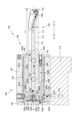
- FIG. 1 is a cross-sectional view showing a tool holding device of one embodiment. It is a sectional view showing a tool holder which constitutes a tool holding device of one embodiment. It is a figure showing the movable member which constitutes a tool holder of one embodiment. It is a sectional view showing a support device which constitutes a tool holding device of one embodiment.
- FIG. 2 is a sectional view of FIG. 1 viewed from the direction of arrow VV.
- FIG. 3 is a diagram showing an example of a tool having a tool passage. It is a figure explaining the operation
- the direction along the center line P of the inner space of the main body portion will be referred to as the “axial direction”.
- the side where the tool is inserted into the inner space of the main body is referred to as the "tip side” or "one axial side.”
- the side opposite to the side where the tool is inserted into the inner space of the main body is referred to as the "rear end side” or the “other axial side.”
- the front end side and the rear end side may be in opposite directions.
- the direction of a line passing through the center line P when viewed from one axial side or the other axial side is referred to as a "radial direction.”
- the side on the center line P side along the radial direction is referred to as the "radially inner side”
- the side opposite to the center line P is referred to as the "radially outer side”.
- the direction along a circle centered on the center line P when viewed from one axial side or the other axial side is referred to as a "circumferential direction.”
- descriptions such as “axial direction”, “tip side”, “rear end side”, “radial direction”, “radially inside”, “radially outside”, and “circumferential” refer to the tool itself.
- ⁇ Axial direction'', ⁇ front end side'', ⁇ rear end side'', ⁇ radial direction'', ⁇ radially inner side'', ⁇ radially outer side'', and ⁇ circumferential direction'' are shown when inserted into the internal space of the section.
- FIG. 1 is a cross-sectional view of the tool holding device 100.
- FIG. 2 is a sectional view of the tool holder 300 that constitutes the tool holder 100. Note that the tool holder 300 shown in FIG. 2 is an embodiment of the tool holder of the present disclosure.
- FIG. 3 is a diagram showing a movable member 500 that constitutes the tool holder 300.
- FIG. 5(a) is a cross-sectional view of the movable member 500.
- FIG. 5(b) is a diagram of FIG. 5(a) viewed from the direction of arrow b.
- FIG. 4 is a sectional view showing the support device 200 that constitutes the tool holding device 100.
- FIG. 5 is a sectional view of FIG. 1 viewed from the direction of arrow VV.
- FIG. 6 is a diagram illustrating an example of a tool having a tool passage that is open at the rear end surface of the tool.
- Tool 700 has an axially extending tool body member 710.
- a blade 720 is provided on the tip side of the tool body member 710.
- the tool body member 710 has a tool body member outer peripheral surface 712.
- the tool body member outer circumferential surface 712 extends along a circle centered on the tool center line T.
- Tool centerline T is the centerline of the alternating body members 710.
- the tool body member 710 has a notch 730 extending in the axial direction on the outer peripheral side.
- the notches 730 are provided at two locations facing each other in the circumferential direction. The number and formation positions of the notches 730 can be selected as appropriate.
- the cutout portion 730 is formed by a cutout surface 731 obtained by cutting out the outer peripheral surface 712 of the tool body member.
- the cutout surface 731 extends in a direction perpendicular to a line passing through the tool centerline T and in the axial direction.
- the notch portion 730 is open to the tool rear end surface 710B. That is, the notch 730 has an opening 730b formed in the tool rear end surface 710B.
- the tool holding member 710 has a tool passage 740 for coolant injection.
- Tool passage 740 extends in the axial direction.
- the tool passage 740 opens to the tool rear end surface 710B. That is, the tool passage 740 has an opening 740b formed in the tool rear end surface 710B.
- the opening 740b is formed in a region closer to the tool center line T than the opening 730b.
- tool passageway 740 is formed in the center of tool body member 710.
- the tool passage 740 has an injection port 740a formed on the distal end side of the tool main body member 710.
- the injection port 740a is formed near the blade 720 so that the coolant is injected in the direction of the blade 720.
- the tool body member outer peripheral surface 712 corresponds to the "tool outer peripheral surface" of the present invention.
- the tool holding device 100 of this embodiment includes a support device 200 and a tool holder 300.
- the tool holder 300 includes a main body, a tool holding mechanism, and a movable member 500.
- the main body portion includes a main body member 400 and a cover 240.
- the cover 240 is attached to the support member 220 that constitutes the support device 200. Therefore, the cover 240 will be described later together with the support device 200.
- the main body member 400 is formed in a cylindrical shape and has a main body member front end surface 400A, a main body member rear end surface 400B, a main body member inner circumferential surface 401, and a main body member outer circumferential surface 402.
- the body member inner peripheral surface 401 forms a body member inner space 400a that extends in the axial direction.
- the main body member inner space 400a has an opening 400C formed in the main body member front end surface 400A and an opening 400D formed in the main body member rear end surface 400B.
- the main body member inner space 400a is formed so that the tool 700 can be inserted from the tip side (opening 400C side).
- the main body member inner circumferential surface 401 has main body member inner circumferential surface portions 401a to 401g.
- the inner peripheral surface portions 401a to 401g of the main body member have a circular cross section.
- Body member inner peripheral surface portions 401a and 401c extend in the axial direction.
- the inner diameter of the inner circumferential surface portion 401c of the main body member is set larger than the inner diameter of the inner circumferential surface portion 401a of the main body member.
- the main body member inner circumferential surface portion 401b extends in the radial direction and forms a step surface connecting the main body member inner circumferential surface portions 401a and 401c.
- the main body member inner peripheral surface portion 401a forms a main body member inner space portion 400b.
- the main body member inner circumferential surface portion 401c forms a main body member inner space portion 400c.
- the main body member inner circumferential surface portion 401b acts as a movement restriction surface that restricts movement of the movable member 500 toward the distal end, which will be described later.
- the inner circumferential surface portion 401a of the main body member is formed such that the tool center line T of the tool 700 extends parallel to the axial direction when the tool 700 is inserted into the inner space portion 400b of the main body member.
- the inner wall of the main body member inner space 400a (main body member inner space portion 400b) is set so that the tool center line T of the tool 700 extends parallel to the axial direction.
- the inner peripheral surface portions 401d to 401g of the main body member form a recessed portion 401A that is recessed toward the outer diameter side and extends in the circumferential direction.
- a ring member 600 which will be described later, is placed in the recess 401A.
- the main body member outer circumferential surface 402 has main body member outer circumferential surface portions 402a to 402c.
- a flange portion 410 extending radially outward is formed by the main body member outer circumferential surface portions 402a, 402b and the main body member distal end surface 400A.
- a through hole 420 is formed at a predetermined location of the flange portion 410 and communicates with the main body member distal end surface 400A and the main body member outer circumferential surface portion 402B.
- a pin 421 is inserted into the through hole 420. The pin 421 is inserted so as to protrude from the outer peripheral surface portion 402b of the main body member.
- the pin 421 is inserted into a recess 223 of the support member 220, which will be described later.
- An O-ring 422 is arranged between the wall surface of the through hole 420 and the pin 421.
- a groove 430 extending in the axial direction is formed on the rear end side of the main body member outer peripheral surface portion 402c.
- a pin 225 which will be described later, is inserted into the groove 430.
- a through hole 440 is formed in the main body member outer circumferential surface 402 at a location corresponding to the main body member inner space portion 400b, and communicates with the main body member inner circumferential surface portion 401a and the main body member outer circumferential surface portion 402c.
- the through holes 440 are formed at two positions facing each other in the circumferential direction, as shown in FIG.
- they are formed at two positions spaced apart in the axial direction.
- a pin 441 (see FIG. 5) is inserted into the through hole 440.
- the pin 441 is inserted into the through hole 440 by screwing together the female screw formed on the inner peripheral surface of the through hole 440 and the male screw formed on the outer periphery of the pin 44. .
- the pin 441 is arranged so as to come into contact with the cutout surface 731 of the tool 700 inserted into the main body member inner space 400a.
- the number and arrangement positions of the through holes 440 and pins 442 can be set as appropriate.
- the pin 441 corresponds to the "rotation prevention member" of the present invention.
- the cutout surface 731 of the tool 700 and the pin 441 constitute the "tool holding mechanism" of the present invention.
- a passage 450 for supplying coolant is formed in the main body member 400.
- the passage 450 includes an axially extending inlet 450a formed in the outer circumferential surface 402 of the main body member, a first outlet 450b formed in the rear end surface 400B of the main body member, and a first outlet 450b formed in the front end surface 400A of the main body member. It has a second outlet 450c. The second outlet 450c is formed so that the coolant can be injected to the blade of the tool inserted into the body member inner space 400a.
- the passage 450 has a first passage 450A and a second passage 450B. The first passage 450A communicates the inlet 450a and the first outlet 450b.
- the first passage 450A supplies the coolant that has flowed into the inlet 450a to the first outlet 450b.
- the second passage 450b communicates the inlet 450a and the second outlet 450c.
- the second passage 450B supplies the coolant that has flowed into the inlet 450a to the second outlet 450c.
- the switching member includes a hole 461 formed in the main body member 400 and a pin 460 inserted into the hole 461.
- the hole 461 extends in the axial direction and is open to the distal end surface 400A of the main body member.
- a female thread is formed on the inner peripheral surface of the hole 461.
- a male thread is formed on the outer circumferential surface of the pin 460 and can be screwed together with a female thread formed on the inner wall of the hole 461.
- the pin 460 is inserted into the hole 461 with its male and female threads screwed together. This allows the pin 460 to move along the direction in which the hole 461 extends.
- the second outflow port 450c corresponds to the "outflow port formed on the front end surface of the main body" of the present invention.
- the second passage 450B corresponds to the "second passage communicating the inlet and the outlet" of the present invention.
- the pin 460 switches the second passage of the present invention into an open state that allows coolant to be supplied from the inlet to the outlet, or a closed state that prohibits the supply of coolant from the inlet to the outlet. "Possible switching member”.
- the movable member 500 is arranged movably within the main body member inner space 400a (more specifically, the main body member inner space portion 400c) along the main member inner peripheral surface 401 (more specifically, the main body member inner peripheral surface portion 401c). Ru.
- the movable member 500 includes a movable member front end surface 500A, a movable member rear end surface 500B, a movable member inner peripheral surface, a movable member outer peripheral surface, a movable member front end surface 500A, and a movable member rear end surface 500B. It has a through hole formed between the two.
- the movable member 500 includes a first member 510, a second member 520, and a third member 530.
- the first member 510 and the second member 520 are made of metal (for example, stainless steel), and the third member 530 is made of an elastic body.
- rubber is used as the elastic body.
- the first member 510 is formed into a cylindrical shape and has a distal end surface 510A, a rear end surface 510B, an inner circumferential surface 511, and an outer circumferential surface 512.
- the inner peripheral surface 511 has inner peripheral surface portions 511a to 511g.
- the outer peripheral surface 512 has outer peripheral surface portions 512a to 512c.
- the inner peripheral surface portions 511a, 511c, 511e, and 511g and the outer peripheral surface 512 extend in the circumferential direction and the axial direction, and have a circular cross section.
- the leading end surface 510A, the rear end surface 510B, and the inner peripheral surface portions 511b, 511d, and 511f extend in the circumferential direction and the radial direction.
- a groove 513 extending in the circumferential direction is formed by the outer peripheral surface portions 512a to 512c.
- An O-ring 514 is disposed within the groove 513.
- the movable member 500 is configured to be movable along the inner circumferential surface portion 401c of the main body member with the O-ring 514 sealing between the outer circumferential surface 512 and the inner circumferential surface portion 401c of the main body member.
- the second member 520 is formed into a cylindrical shape and has a distal end surface 520A, a rear end surface 520B, an inner circumferential surface 521, and an outer circumferential surface 522.
- the outer peripheral surface 522 has outer peripheral surface portions 522a to 522c.
- the inner circumferential surface 521 and the outer circumferential surface portions 522a and 522c extend in the circumferential direction and the axial direction, and have a circular cross section.
- the distal end surface 520A, the rear end surface 520B, and the outer circumferential surface portion 522b extend in the circumferential direction and the radial direction.
- the second member 520 is inserted into the inner space formed by the inner peripheral surface 511 of the first member 510.
- the outer circumferential surface portions 522b and 522c of the second member 520 abut on the inner circumferential surface portions 511f and 511g of the first member 510, respectively. Axial movement is restricted.
- the third member 530 is formed into a cylindrical shape and has a distal end surface 530A, a rear end surface 530B, an inner circumferential surface 531, and an outer circumferential surface 532.
- the outer peripheral surface 532 has outer peripheral surface portions 532a to 522e.
- the inner circumferential surface 531 and the outer circumferential surface portions 532a, 532c, and 532e extend in the circumferential direction and the axial direction, and have a circular cross section.
- the distal end surface 530A, the rear end surface 530B, and the outer peripheral surface portions 532b and 532d extend in the circumferential direction and the radial direction.
- the third member 530 is disposed between the first member 510 and the second member 520.
- the protrusion formed by the inner peripheral surface portions 511b to 511d of the first member 510 fits into the recess formed by the outer peripheral surface portions 532b to 532d of the third member 530. This restricts movement of the third member in the radial and axial directions relative to the first member 510. Further, the outer circumferential surface portion 522b of the second member 520 abuts the rear end surface 530B of the third member 530. This restricts movement of the second member 520 in the axial direction with respect to the third member 530.
- the distal end surface 510A of the first member 520, the distal end surface 520A of the second member 520, and the distal end surface 530A of the third member 530 form a movable member distal end surface 500A.
- the tip surfaces 510A, 520A, and 530A constitute a movable member tip surface portion of the movable member tip surface 500A.
- the rear end surface 510B of the first member 510 and the rear end surface 520B of the second member 520 form a movable member rear end surface 500B.
- the rear end surfaces 510B and 520B constitute a movable member rear end surface portion of the movable member rear end surface 500B.
- the inner circumferential surface 521 of the second member 520 forms the inner circumferential surface of the movable member.
- the through hole 540 of the second member 520 forms a through hole of the movable member 500.
- the outer peripheral surface 512 of the first member 510 forms the outer peripheral surface of the movable member.
- the center line of the through hole 540 of the movable member 500 is arranged to substantially coincide with the center line P of the main body member inner space 400a when the movable member 500 is disposed within the main body member inner space portion 500c. It is configured. Further, the inner diameter of the through hole 540 of the movable member 500 (specifically, the inner diameter of the opening 540a on the tip side of the through hole 540) is the same as that of the tool passage 740 of the tool 700 (specifically, the inner diameter of the opening 540a on the rear end side of the tool passage 740). It is set approximately equal to the inner diameter of the opening 740b).
- the movable member tip end surface portion 530A of the movable member 500 is arranged around the through hole 540 (specifically, the opening 540a of the through hole 540). Further, the movable member distal end surface portion 530A projects further toward the distal end than the movable member distal end surface portions 510A and 520A. As a result, when the movable member distal end surface 500A of the movable member 500 comes into contact with the tool rear end surface 710B of the tool 700, the through hole 540 (opening 540a) of the movable member 500 and the tool passage 740 (opening 740b) are in a state facing each other.
- the movable member front end surface portion 530A abuts around the tool passage 740 (opening 740b) of the tool rear end surface 710B. That is, no space is generated between the movable member tip end surface portion 530A and the tool rear end surface 710B. Therefore, coolant can be prevented from flowing from the through hole 540 of the movable member 500 to the tool notch 730 of the tool 700. Furthermore, the movable member tip surface portion 530A is formed of an elastic body. Thereby, the movable member tip end surface portion 530A and the tool rear end surface 710B can be reliably brought into contact.
- the description ⁇ a state in which the through hole 540 (opening 540a) of the movable member 500 and the tool passage 740 (opening 740b) are opposed'' refers to ⁇ the state in which the through hole 540 (opening 540a) of the movable member 500 and the tool passage 740 (A state in which the openings 740b) at least partially overlap in the axial direction.
- the ring member 600 has a ring member distal end surface 600A, a ring member rear end surface 600B, and a through hole 600a formed between the ring member distal end surface 600A and the ring member rear end surface 600B.
- the ring member front end surface 600A and the ring member rear end surface 600B extend in the circumferential direction and the radial direction.
- the ring member outer peripheral surface 602 is formed in a circular shape. Note that the shape of the ring member outer peripheral surface 6002 is not limited to a circle.
- the ring member 600 is disposed in a recess 401A formed on the rear end side of the main body member inner space 400a.
- the ring member distal end surface 600A of the ring member 600 acts as a movement restriction surface that restricts movement of the movable member 500 toward the rear end side. Furthermore, the through hole 614 of the ring member 600 functions as a coolant inlet for supplying coolant to the main body member inner space 400a.
- the support device 200 has a base 210 and a support section.
- the base 210 has a mounting surface 211 to which a support section is attached. Furthermore, a passage 212 for supplying coolant is formed in the base 210.
- the support section includes a support member 220 and a sleeve 230.
- the support member 220 is formed in a cylindrical shape, and includes a support member front end surface 220A, a support member rear end surface 330B, a support member inner peripheral surface 221, a support member inner space 220a formed by the support member inner peripheral surface 221, and an attached surface 222. have.
- the support member inner peripheral surface 221 has a circular cross section.
- the support member 220 is attached to the base 210 so that the attachment surface 222 faces the attachment surface 211.
- a recess 223 is formed in the support member distal end surface 220A.
- a through hole 224 is formed in the support member 220 between the outer peripheral surface of the support member and the peripheral surface of the support member.
- a female thread is formed on the inner peripheral surface of the through hole 224 and can be screwed to a male thread formed on the outer peripheral side of the pin 225 .
- a passage 226 is formed in the support member 220 at a position opposite to the passage 212 formed in the base 210.
- the sleeve 230 is formed into a cylindrical shape and has a sleeve inner space 230a formed by a sleeve front end surface 230A, a sleeve rear end surface 230B, a sleeve inner peripheral surface 231, a sleeve outer peripheral surface 232, and a sleeve inner peripheral surface 231.
- the sleeve inner circumferential surface 231 and the sleeve outer circumferential surface 232 have circular cross sections.
- the sleeve outer circumferential surface 232 has sleeve outer circumferential surface portions 232a to 232e.
- the outer diameter of the sleeve outer circumferential surface portion 232c is set smaller than the outer diameter of the sleeve outer circumferential surface portions 232a and 232e. Further, the outer diameters of the sleeve outer peripheral surface portions 232b and 232d are set smaller than the outer diameter of the sleeve outer peripheral surface portion 232c. As a result, thin grip portions 234a and 234b are formed between the sleeve inner peripheral surface 231 and the sleeve outer peripheral surface portions 232a and 232d. The sleeve 230 is inserted and fixed within the support member inner space 220a.
- pressurized chambers 233a and 233b are formed between the support member inner peripheral surface 221 and the sleeve outer peripheral surface portions 232b and 232d. Further, a communication passage 233c communicating with the pressurizing chambers 233a and 233b is formed between the support member inner circumferential surface 221 and the sleeve outer circumferential surface portion 232c.
- a support member inner space is formed by the support member inner space 220a and the sleeve inner space 230a. Further, the support member inner circumferential surface 221 (specifically, the support member inner circumferential surface portion 221b) and the sleeve inner circumferential surface 231 form a support portion inner circumferential surface.
- a through hole 235 is formed in the sleeve 230 at a position opposite to the through hole 224 formed in the support member 220.
- a passage 236 is formed in the sleeve 230 at a position opposite to the passage 226 formed in the support member 220.
- the main body member 400 is inserted into the sleeve inner space 230a (support part inner space). At this time, the main body member 400 is inserted until the main body member outer peripheral surface portion 402b comes into contact with the support member distal end surface 220A. This defines the position of the main body member 400 (tool holder 300) in the axial direction with respect to the support member 220 (support portion). Further, the pin 421 (see FIG. 2) inserted into the through hole 420 of the main body member 400 is inserted into the recess 223 formed in the support member 220. This defines the position of the main body member 400 (tool holder 300) in the circumferential direction with respect to the support member 220 (support portion).
- the pin 225 is moved radially inward and inserted into the through hole 224 of the support member 220 and the through hole 235 of the sleeve 230. Furthermore, the tip of the pin 225 is inserted into the groove 430 of the main body member 400. This restricts movement of the main body member 400 (tool holder 300) toward the rear end and rotation (position) along the circumferential direction with respect to the support member 220 (support portion). Note that when the position of the main body member 400 with respect to the support member 220 along the circumferential direction is defined, the inlet port 450a of the main body member 400 is arranged at a position facing the passage 236 of the sleeve 230.
- the pin 421 and the pin 225 are provided, but only one of them may be provided. That is, the pin 421 or the pin 225 may be configured to define the position of the main body member 400 (tool holder 300) in the circumferential direction with respect to the support member 220 (support portion).
- the pressure within the pressurizing chambers 233a and 233b is increased.
- portions of sleeve inner peripheral surface 231 corresponding to gripping portions 234a and 234b are elastically deformed inward.
- the main body member outer circumferential surface 402 of the main body member 400 is held between the gripping parts 234a and 234b.
- a cover 240 is attached to the support member 220.
- the cover 240 is attached to the support member 220 such that the front end surface 240A of the cover 240 contacts the rear end surface 220B of the support member 220.
- An O-ring 242 is disposed between the front end surface 240A of the cover 240 and the rear end surface 220B of the support member 220.
- the cover 240 closes the rear end of the main body member inner space 400a of the main body member 400 inserted into the sleeve inner space 230a (support part inner space). That is, the main body inner space is formed by the main body member inner space 400a and the cover inner space 240a.
- the coolant supplied from the passage 212 of the base 210 flows through the passage 226 of the support member 220, the passage 236 of the sleeve 230, the inlet 450a of the main body member 400, the first passage 450A, and the first outlet 450b. and is supplied into the inner space of the main body.
- the main body member 400 and the cover 240 constitute a main body portion of the tool holder 300.
- the main body inner space of the tool holder 300 is formed by the main body member inner space 400a and the cover inner space 240a.
- the inner circumferential surface of the main body portion of the tool holder 300 is formed by the inner circumferential surface of the main body member 401 and the inner circumferential surface of the cover 241 .
- pin 460 is set in a position that switches second passageway 450B to a closed state. That is, the supply of coolant from the inlet 450a to the second outlet 450c is stopped.
- the movable member rear end surface 500B (movable member rear end surface portion 510B) of the movable member 500 is in contact with the ring member distal end surface 600A of the ring member 600.
- the tool rear end surface 710B of the tool 700 is in contact with the movable member distal end surface 500A (movable member distal end surface portion 530A) of the movable member 500.
- the tool protrusion length is L1.
- the coolant supplied from the passage 212 of the base 210 enters the inner space of the main body through the inlet 450a, the first passage 450A, and the first outlet 450b of the main body member 400. flows to The coolant then flows into the tool passage 740 via the through hole 540 of the movable member 500.
- coolant pressure is applied to the movable member rear end surface 500B (movable member rear end surface portions 520B and 530B) of the movable member 500, but since the tool 700 does not move toward the distal end, the movable member 500 also does not move toward the distal end. . Therefore, coolant does not flow from the through hole 540 of the movable member 500 to the cutout 730 of the tool 700.
- the tool rear end surface 710B is located at a position closer to the tip than the position shown in FIG.
- the tool protrusion length is L2 (>L1).
- the pin 460 is set at a position that switches the second passage 450B to the closed state.
- the movable member 500 is located in a region between the ring member distal end surface 600A and the tool rear end surface 710B of the ring member 600. Note that FIG.
- FIG. 8 shows a state in which coolant is supplied into the inner space of the main body.
- the coolant flows through the through hole 540 of the movable member 500. flows.
- the pressure of the coolant is applied to the rear end surface of the movable member 500 (the rear end surface portions 510B and 520B of the movable member). Therefore, the movable member 500 moves toward the distal end side. Then, the movable member front end surface 500A of the movable member 500 comes into contact with the tool rear end surface 700B of the tool 700.
- the movable member tip surface 500A (movable member tip surface portion 530A) It abuts the area around the tool passage 740 (opening 740b) of the end surface 710B. Therefore, coolant does not flow from the through hole 540 of the movable member 500 to the cutout 730 of the tool 700.
- the main body member inner space portion 400c formed by the main body member inner peripheral surface portion 401c is divided by the movable member 500. That is, the main body member inner space portion 400c is divided into a first divided inner space portion 400c1 on the distal side of the movable member 500 and a second divided inner space portion 400c2 on the rear end side of the movable member 500.
- a notch 830 having an opening 830b is formed on the tool rear end surface 810B.
- a tool passage having an opening is not formed in the tool rear end surface 810B.
- coolant is allowed to be supplied from the inlet 450a to the second outlet 450c.
- the coolant supplied to the inlet 450a is supplied into the main body inner space via the first passage 450A, and flows to the second outlet 450c via the second passage 450B.
- the movable member distal end surface 500A movable member wire distal end surface 530A
- the tool 800 does not have a tool passage, coolant does not flow into the tool passage.
- a tool holding mechanism constituted by a notch surface forming a notch portion of the tool and a rotation preventing member
- other known tool holding mechanisms may be used.
- a tool holding mechanism configured by a collet that clamps the outer peripheral surface of the tool as disclosed in Patent Document 1
- a tool holding mechanism that is configured by a pressurizing chamber and an elastically deformable gripping portion can be used.
- multiple tool holding mechanisms can be used.
- a tool holding mechanism composed of a collet and a tool holding mechanism composed of a cutout surface of the tool and a rotation prevention member can be used.
- the movable member 500 is composed of three members (510 to 530), but the present invention is not limited thereto.
- the movable member 500 can also be composed of one member.
- the movable member 500 can also be composed of a plurality of members other than three.
- the movable member distal end surface 500A is divided into a movable member distal end surface portion 530A and a movable member distal end surface portion 520A disposed at a position on the rear end side and radially inside the movable member distal end surface portion 530A.
- the movable member distal end surface portion 510A is disposed radially outward and on the rear end side of the movable member distal end surface portion 530A, but the present invention is not limited thereto. That is, the movable member distal end surface 500A prevents coolant from flowing from the opening 540a of the through hole 540 of the movable member 500 to the notch 730 of the tool 710 when the movable member distal end surface 500A and the tool rear end surface 710B are in contact with each other. It would be good if it could be prevented.
- the movable member tip surface 500A can be formed by one surface.
- the movable member distal end surface 500A can be formed by a plurality of movable member distal end surface portions other than three. Furthermore, the arrangement position of the distal end surface portion of the movable member that protrudes toward the distal end side can be changed as appropriate.
- a tool holding device a tool holder is also disclosed.
- the main body of the tool holder is composed of the main body member and the cover, an integrally formed member may also be used.
- the ring member is disposed within the space inside the main body member, the ring member can also be formed integrally with the main body member. Moreover, the ring member can also be omitted.
- the ring member distal end surface of the ring member is used as a movement restriction surface that restricts movement of the movable member toward the rear end side
- the inner circumferential surface portion of the main body member is used as a movement restriction surface that restricts movement of the movable member toward the distal end side.
- the movement restriction surface is used as a surface, the movement restriction surface is not limited to this. Further, the movement regulating surface can also be omitted.
- the support device is composed of a base, a support member, and a sleeve, it is not limited thereto.
- the rotation prevention member that prevents rotation of the tool may be engaged with a notch (including a notch surface) formed in the tool, and rotation prevention members with various configurations can be used. Further, the number and arrangement positions of the rotation preventing members can be changed as appropriate. Each configuration described in the detailed description can be used alone, or a plurality of appropriately selected configurations can be used in combination.
- Tool holding device 100 Tool holding device 200 Support device 210 Base 211 Mounting surface 212 Passage 220 Supporting member 220A Supporting member tip surface 220B Supporting member rear end surface 221 Supporting member inner circumferential surface 221a to 221c Supporting member inner circumferential surface portion 222 Mounted surface 223 Recessed portion 224 Through hole 225 Pin 226 Through hole 230 Sleeve 230A Sleeve distal end surface 230B Sleeve rear end surface 231 Sleeve inner circumferential surface 232 Sleeve outer circumferential surface 232a to 232e Sleeve inner circumferential surface portions 233a, 233b Pressurizing chamber 233c Communication passages 234a, 234b Gripping portion 235, 236 Through hole 240 Cover 240A Cover tip surface 240a Cover inner space 241 Cover inner peripheral surface 300 Tool holder 400 Body member 400A Body member tip surface 400B Body member rear end surface 400a Body member inner spaces 400b, 400c Body member inner space portion 401 Main body Member inner peripheral surface 401A Recesses 401a to 401g Main
Landscapes
- Engineering & Computer Science (AREA)
- Mechanical Engineering (AREA)
- Auxiliary Devices For Machine Tools (AREA)
Priority Applications (5)
| Application Number | Priority Date | Filing Date | Title |
|---|---|---|---|
| CN202280093219.3A CN118900746A (zh) | 2022-03-10 | 2022-03-10 | 刀具保持件和刀具保持装置 |
| EP22930868.9A EP4487994A4 (en) | 2022-03-10 | 2022-03-10 | Tool holding fixture and tool holding device |
| US18/844,076 US20250170656A1 (en) | 2022-03-10 | 2022-03-10 | Tool holder and tool holding device |
| JP2024505779A JPWO2023170887A1 (https=) | 2022-03-10 | 2022-03-10 | |
| PCT/JP2022/010709 WO2023170887A1 (ja) | 2022-03-10 | 2022-03-10 | 工具保持具および工具保持装置 |
Applications Claiming Priority (1)
| Application Number | Priority Date | Filing Date | Title |
|---|---|---|---|
| PCT/JP2022/010709 WO2023170887A1 (ja) | 2022-03-10 | 2022-03-10 | 工具保持具および工具保持装置 |
Publications (1)
| Publication Number | Publication Date |
|---|---|
| WO2023170887A1 true WO2023170887A1 (ja) | 2023-09-14 |
Family
ID=87936400
Family Applications (1)
| Application Number | Title | Priority Date | Filing Date |
|---|---|---|---|
| PCT/JP2022/010709 Ceased WO2023170887A1 (ja) | 2022-03-10 | 2022-03-10 | 工具保持具および工具保持装置 |
Country Status (5)
| Country | Link |
|---|---|
| US (1) | US20250170656A1 (https=) |
| EP (1) | EP4487994A4 (https=) |
| JP (1) | JPWO2023170887A1 (https=) |
| CN (1) | CN118900746A (https=) |
| WO (1) | WO2023170887A1 (https=) |
Citations (7)
| Publication number | Priority date | Publication date | Assignee | Title |
|---|---|---|---|---|
| JPH0516015U (ja) * | 1991-03-07 | 1993-03-02 | 三菱マテリアル株式会社 | 切削工具 |
| JPH0627046U (ja) * | 1992-09-10 | 1994-04-12 | 株式会社日研工作所 | 工具への流体供給装置 |
| JPH08257870A (ja) * | 1995-01-27 | 1996-10-08 | Toyota Motor Corp | 工具ホルダ |
| JPH0994731A (ja) * | 1995-10-03 | 1997-04-08 | Ikegai Corp | 高圧クーラント用工具装置 |
| JP2001087969A (ja) | 1999-09-16 | 2001-04-03 | Seiwa Seiki Kk | サイドロックホルダ |
| JP2001287135A (ja) | 2000-04-04 | 2001-10-16 | Horkos Corp | 工作機械用工具ホルダ並びにこの工具ホルダに用いる刃具及び、この工具ホルダに用いるツールドライバ |
| JP2003181743A (ja) * | 2001-12-17 | 2003-07-02 | Seiwa Seiki Kk | 旋盤用工具ホルダ |
Family Cites Families (1)
| Publication number | Priority date | Publication date | Assignee | Title |
|---|---|---|---|---|
| DD204648A1 (de) * | 1981-12-28 | 1983-12-07 | Dieter Guenther | Durchflusssteuereinrichtung fuer gas- und fluessigmedien in einer werkzeugmaschinenarbeitsspindel |
-
2022
- 2022-03-10 JP JP2024505779A patent/JPWO2023170887A1/ja active Pending
- 2022-03-10 CN CN202280093219.3A patent/CN118900746A/zh active Pending
- 2022-03-10 WO PCT/JP2022/010709 patent/WO2023170887A1/ja not_active Ceased
- 2022-03-10 EP EP22930868.9A patent/EP4487994A4/en active Pending
- 2022-03-10 US US18/844,076 patent/US20250170656A1/en active Pending
Patent Citations (7)
| Publication number | Priority date | Publication date | Assignee | Title |
|---|---|---|---|---|
| JPH0516015U (ja) * | 1991-03-07 | 1993-03-02 | 三菱マテリアル株式会社 | 切削工具 |
| JPH0627046U (ja) * | 1992-09-10 | 1994-04-12 | 株式会社日研工作所 | 工具への流体供給装置 |
| JPH08257870A (ja) * | 1995-01-27 | 1996-10-08 | Toyota Motor Corp | 工具ホルダ |
| JPH0994731A (ja) * | 1995-10-03 | 1997-04-08 | Ikegai Corp | 高圧クーラント用工具装置 |
| JP2001087969A (ja) | 1999-09-16 | 2001-04-03 | Seiwa Seiki Kk | サイドロックホルダ |
| JP2001287135A (ja) | 2000-04-04 | 2001-10-16 | Horkos Corp | 工作機械用工具ホルダ並びにこの工具ホルダに用いる刃具及び、この工具ホルダに用いるツールドライバ |
| JP2003181743A (ja) * | 2001-12-17 | 2003-07-02 | Seiwa Seiki Kk | 旋盤用工具ホルダ |
Non-Patent Citations (1)
| Title |
|---|
| See also references of EP4487994A4 |
Also Published As
| Publication number | Publication date |
|---|---|
| JPWO2023170887A1 (https=) | 2023-09-14 |
| US20250170656A1 (en) | 2025-05-29 |
| EP4487994A4 (en) | 2025-05-07 |
| CN118900746A (zh) | 2024-11-05 |
| EP4487994A1 (en) | 2025-01-08 |
Similar Documents
| Publication | Publication Date | Title |
|---|---|---|
| US6729627B2 (en) | Capped collet and collet cap | |
| WO2016117461A1 (ja) | バイト | |
| JP2007510555A (ja) | チャックのための中間ブッシュおよびその製造方法 | |
| TWI750270B (zh) | 冷卻液聯結裝置 | |
| JP2018525238A (ja) | クーラント供給部を有する金属切削工具 | |
| TWI706826B (zh) | 工作機械用之旋轉工作台裝置 | |
| CN105121078A (zh) | 液压卡盘 | |
| WO1995029038A1 (en) | Spindle device | |
| WO2023170887A1 (ja) | 工具保持具および工具保持装置 | |
| JPWO2023170887A5 (https=) | ||
| KR20230019053A (ko) | 새로운 댐핑 기능을 갖는 수축 끼워맞춤 척 | |
| KR101050411B1 (ko) | 터렛용 공구홀더 | |
| KR101195753B1 (ko) | 조정나사가 설치된 터렛용 공구홀더 | |
| JP4637217B2 (ja) | ツールシャンクおよび工作機械 | |
| KR101076711B1 (ko) | 스토퍼가 내장된 터렛용 공구홀더 | |
| JP4309988B2 (ja) | 工作機械の主軸台および軸物ワークの加工方法 | |
| WO2023053471A1 (ja) | 主軸装置 | |
| KR20150072642A (ko) | 클램핑 장치 | |
| JP7416363B2 (ja) | ハイドロチャック | |
| KR100600024B1 (ko) | 터렛에 적용되는 절삭유 유로변경을 위한 절삭유 어댑터 | |
| JP3252280U (ja) | クーリング効果を有するツールホルダー | |
| US20260108951A1 (en) | Body and cutting tool | |
| TWM504650U (zh) | 直驅式放電加工機旋轉軸 | |
| JP7554705B2 (ja) | 工作機械の主軸装置 | |
| KR102005581B1 (ko) | 절삭유 공급 장치 |
Legal Events
| Date | Code | Title | Description |
|---|---|---|---|
| 121 | Ep: the epo has been informed by wipo that ep was designated in this application |
Ref document number: 22930868 Country of ref document: EP Kind code of ref document: A1 |
|
| ENP | Entry into the national phase |
Ref document number: 2024505779 Country of ref document: JP Kind code of ref document: A |
|
| WWE | Wipo information: entry into national phase |
Ref document number: 18844076 Country of ref document: US Ref document number: 202280093219.3 Country of ref document: CN |
|
| WWE | Wipo information: entry into national phase |
Ref document number: 2022930868 Country of ref document: EP |
|
| ENP | Entry into the national phase |
Ref document number: 2022930868 Country of ref document: EP Effective date: 20241001 |
|
| NENP | Non-entry into the national phase |
Ref country code: DE |
|
| WWP | Wipo information: published in national office |
Ref document number: 18844076 Country of ref document: US |