WO2023162405A1 - 移動装置および無人飛行装置 - Google Patents
移動装置および無人飛行装置 Download PDFInfo
- Publication number
- WO2023162405A1 WO2023162405A1 PCT/JP2022/045446 JP2022045446W WO2023162405A1 WO 2023162405 A1 WO2023162405 A1 WO 2023162405A1 JP 2022045446 W JP2022045446 W JP 2022045446W WO 2023162405 A1 WO2023162405 A1 WO 2023162405A1
- Authority
- WO
- WIPO (PCT)
- Prior art keywords
- drone
- landing
- engaging portion
- leveling table
- control device
- Prior art date
- Legal status (The legal status is an assumption and is not a legal conclusion. Google has not performed a legal analysis and makes no representation as to the accuracy of the status listed.)
- Ceased
Links
Images





Classifications
-
- B—PERFORMING OPERATIONS; TRANSPORTING
- B64—AIRCRAFT; AVIATION; COSMONAUTICS
- B64U—UNMANNED AERIAL VEHICLES [UAV]; EQUIPMENT THEREFOR
- B64U80/00—Transport or storage specially adapted for UAVs
- B64U80/80—Transport or storage specially adapted for UAVs by vehicles
- B64U80/86—Land vehicles
-
- B—PERFORMING OPERATIONS; TRANSPORTING
- B64—AIRCRAFT; AVIATION; COSMONAUTICS
- B64C—AEROPLANES; HELICOPTERS
- B64C27/00—Rotorcraft; Rotors peculiar thereto
- B64C27/04—Helicopters
- B64C27/08—Helicopters with two or more rotors
-
- B—PERFORMING OPERATIONS; TRANSPORTING
- B64—AIRCRAFT; AVIATION; COSMONAUTICS
- B64C—AEROPLANES; HELICOPTERS
- B64C39/00—Aircraft not otherwise provided for
- B64C39/02—Aircraft not otherwise provided for characterised by special use
-
- B—PERFORMING OPERATIONS; TRANSPORTING
- B64—AIRCRAFT; AVIATION; COSMONAUTICS
- B64U—UNMANNED AERIAL VEHICLES [UAV]; EQUIPMENT THEREFOR
- B64U10/00—Type of UAV
- B64U10/10—Rotorcrafts
- B64U10/13—Flying platforms
-
- B—PERFORMING OPERATIONS; TRANSPORTING
- B64—AIRCRAFT; AVIATION; COSMONAUTICS
- B64U—UNMANNED AERIAL VEHICLES [UAV]; EQUIPMENT THEREFOR
- B64U10/00—Type of UAV
- B64U10/10—Rotorcrafts
- B64U10/13—Flying platforms
- B64U10/14—Flying platforms with four distinct rotor axes, e.g. quadcopters
-
- B—PERFORMING OPERATIONS; TRANSPORTING
- B64—AIRCRAFT; AVIATION; COSMONAUTICS
- B64U—UNMANNED AERIAL VEHICLES [UAV]; EQUIPMENT THEREFOR
- B64U10/00—Type of UAV
- B64U10/20—Vertical take-off and landing [VTOL] aircraft
-
- B—PERFORMING OPERATIONS; TRANSPORTING
- B64—AIRCRAFT; AVIATION; COSMONAUTICS
- B64U—UNMANNED AERIAL VEHICLES [UAV]; EQUIPMENT THEREFOR
- B64U20/00—Constructional aspects of UAVs
- B64U20/80—Arrangement of on-board electronics, e.g. avionics systems or wiring
- B64U20/87—Mounting of imaging devices, e.g. mounting of gimbals
-
- B—PERFORMING OPERATIONS; TRANSPORTING
- B64—AIRCRAFT; AVIATION; COSMONAUTICS
- B64U—UNMANNED AERIAL VEHICLES [UAV]; EQUIPMENT THEREFOR
- B64U30/00—Means for producing lift; Empennages; Arrangements thereof
- B64U30/20—Rotors; Rotor supports
-
- B—PERFORMING OPERATIONS; TRANSPORTING
- B64—AIRCRAFT; AVIATION; COSMONAUTICS
- B64U—UNMANNED AERIAL VEHICLES [UAV]; EQUIPMENT THEREFOR
- B64U50/00—Propulsion; Power supply
- B64U50/30—Supply or distribution of electrical power
- B64U50/37—Charging when not in flight
-
- B—PERFORMING OPERATIONS; TRANSPORTING
- B64—AIRCRAFT; AVIATION; COSMONAUTICS
- B64U—UNMANNED AERIAL VEHICLES [UAV]; EQUIPMENT THEREFOR
- B64U70/00—Launching, take-off or landing arrangements
- B64U70/90—Launching from or landing on platforms
- B64U70/92—Portable platforms
- B64U70/93—Portable platforms for use on a land or nautical vehicle
-
- B—PERFORMING OPERATIONS; TRANSPORTING
- B64—AIRCRAFT; AVIATION; COSMONAUTICS
- B64U—UNMANNED AERIAL VEHICLES [UAV]; EQUIPMENT THEREFOR
- B64U70/00—Launching, take-off or landing arrangements
- B64U70/90—Launching from or landing on platforms
- B64U70/95—Means for guiding the landing UAV towards the platform, e.g. lighting means
-
- B—PERFORMING OPERATIONS; TRANSPORTING
- B64—AIRCRAFT; AVIATION; COSMONAUTICS
- B64U—UNMANNED AERIAL VEHICLES [UAV]; EQUIPMENT THEREFOR
- B64U70/00—Launching, take-off or landing arrangements
- B64U70/90—Launching from or landing on platforms
- B64U70/99—Means for retaining the UAV on the platform, e.g. dogs or magnets
-
- B—PERFORMING OPERATIONS; TRANSPORTING
- B64—AIRCRAFT; AVIATION; COSMONAUTICS
- B64U—UNMANNED AERIAL VEHICLES [UAV]; EQUIPMENT THEREFOR
- B64U80/00—Transport or storage specially adapted for UAVs
- B64U80/20—Transport or storage specially adapted for UAVs with arrangements for servicing the UAV
-
- B—PERFORMING OPERATIONS; TRANSPORTING
- B64—AIRCRAFT; AVIATION; COSMONAUTICS
- B64U—UNMANNED AERIAL VEHICLES [UAV]; EQUIPMENT THEREFOR
- B64U80/00—Transport or storage specially adapted for UAVs
- B64U80/20—Transport or storage specially adapted for UAVs with arrangements for servicing the UAV
- B64U80/25—Transport or storage specially adapted for UAVs with arrangements for servicing the UAV for recharging batteries; for refuelling
-
- B—PERFORMING OPERATIONS; TRANSPORTING
- B64—AIRCRAFT; AVIATION; COSMONAUTICS
- B64U—UNMANNED AERIAL VEHICLES [UAV]; EQUIPMENT THEREFOR
- B64U80/00—Transport or storage specially adapted for UAVs
- B64U80/30—Transport or storage specially adapted for UAVs with arrangements for data transmission
-
- B—PERFORMING OPERATIONS; TRANSPORTING
- B64—AIRCRAFT; AVIATION; COSMONAUTICS
- B64U—UNMANNED AERIAL VEHICLES [UAV]; EQUIPMENT THEREFOR
- B64U2101/00—UAVs specially adapted for particular uses or applications
- B64U2101/30—UAVs specially adapted for particular uses or applications for imaging, photography or videography
Definitions
- the present invention relates to a mobile device and an unmanned flying device, and more particularly to a mobile device that facilitates takeoff and landing of an unmanned flying device and an unmanned flying device that is space efficient.
- Patent Document 1 discloses that an unmanned flying object is charged at the take-off/landing port.
- Patent Document 1 does not take into consideration that the work machine is used on a slope, and if the takeoff/landing port is sloped, there is a risk that the unmanned air vehicle will not be able to take off and land. Also, Patent Literature 1 does not disclose supplying fluid to an unmanned aerial vehicle.
- a second object of the present invention is to provide an unmanned flying device with good space efficiency even when a power receiving device and a fluidic device are provided.
- a mobile device comprises a main unit that travels by a traveling device, a takeoff and landing unit provided in the main unit for taking off and landing of an unmanned flying object, and a takeoff and landing unit provided in the takeoff and landing unit for adjusting an amount of inclination with respect to a vertical axis.
- An unmanned flying device comprises a flight device having a propeller; a second engaging portion that engages with a first engaging portion provided on the landing portion when landing on the landing portion; A power receiving device provided outside the second engaging portion, and a fluid device provided inside the second engaging portion.
- the take-off/landing section is provided with a leveling table capable of adjusting the amount of inclination with respect to the vertical axis, it is possible to realize a mobile device that facilitates take-off and landing of the unmanned air vehicle.
- the power receiving device is provided outside the second engaging portion, and the fluidic device is provided inside the second engaging portion, thereby realizing an unmanned flying device with good space efficiency. can do.
- FIG. 4 is a schematic diagram showing a state in which the transport device is on a slope and the drive shaft is driven;
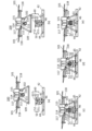
- FIG. 4A is a diagram showing how the drone lands on the take-off and landing section,
- FIG. 4A is a diagram showing the drone being obliquely above the table section, and
- FIG. 4B is a diagram showing the drone being above the table section.
- FIG. 4(c) is a diagram showing how the tapered portion of the second engaging portion contacts the packing, and FIG. 4(d) shows how the power transmitting electrode and the power receiving electrode come into contact.
- FIG. 4E is a diagram showing how the legs of the drone are held by the holding part. 4 is a flow chart executed by a control device;
- FIG. 5 is a schematic diagram of a hydraulic excavator representing the second embodiment;
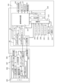
- FIG. 10 is a block diagram of main parts of a hydraulic excavator and a drone according to the second embodiment;
- FIG. 11 is a schematic diagram of a hydraulic excavator representing the third embodiment;
- a construction machine according to an embodiment of the present invention will be described in detail below based on the attached drawings.
- the present invention is not limited by the embodiments described below.
- the transport device 1 that supports a UAV (Unmanned Aerial Vehicle, hereinafter referred to as a drone 100), which is an unmanned aerial vehicle that flies over a slope.
- UAV Unmanned Aerial Vehicle
- the vertical direction is defined as the Z direction
- the biaxial directions orthogonal to each other in the horizontal plane are defined as the X direction and the Y direction.
- FIG. 1A and 1B are schematic diagrams of a conveying apparatus 1 representing the first embodiment
- FIG. 1A is a top view
- FIG. 1B is a front view
- FIG. 1C is a side view
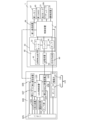
- FIG. 2 is a block diagram of main parts of the transport device 1 and the drone 100 of the first embodiment.
- FIG. 1(b) is shown as a cross section taken along the line AA of FIG. 1(a).
- the conveying apparatus 1 of the first embodiment is of an automatic operation type or a remote operation type without a driver's seat.
- the transport device 1 includes a traveling device 10, a base portion 20, a main body portion 30, a leveling portion 40, a power transmission device 50, a fluid supply portion 60, an imaging device 55, and a first GNSS 65 (Global Navigation Satellite System). , a first communication device 66 , a first memory 67 and a control device 70 .
- a traveling device 10 a base portion 20, a main body portion 30, a leveling portion 40, a power transmission device 50, a fluid supply portion 60, an imaging device 55, and a first GNSS 65 (Global Navigation Satellite System).
- GNSS 65 Global Navigation Satellite System
- the traveling device 10 moves the conveying device 1, and has driving wheels 11, driven wheels 12, crawler belts 13, and supports .
- the travel device 10 also includes a travel motor 15 , a central frame 16 , a pair of side frames 17 , a pair of link mechanisms 18 , and a coupler 19 .
- the travel device 10 is detachable from the base portion 20 by a coupler 19 (details will be described later).
- one driving wheel 11 and two driven wheels 12 form a triangular shape.
- a plurality of driven wheels smaller than the two driven wheels 12 are provided between the two driven wheels 12 .
- the crawler belt 13 is wound around one drive wheel 11 and two driven wheels 12 .
- the support 14 rotatably supports the drive wheel 11 and the driven wheel 12 . Since there are four triangular crawler belt-type traveling bodies in the first embodiment, the conveying apparatus 1 can travel stably even on rough terrain.
- the traveling device 10 an endless track in which crawler belts are wound around the front wheels and the rear wheels may be used.
- the traveling motor 15 (see FIG. 2) employs an in-wheel motor that transmits the driving force to the driving wheels 11 on the rear side of the driving wheels 11 .
- the rotating shaft of the in-wheel motor is connected to the rotating shaft of the driving wheel 11 , and the rotating driving force of the in-wheel motor rotates the driving wheel 11 , thereby transmitting the driving force to the crawler belt 13 .
- a motor different from the in-wheel motor may be employed as the traveling motor 15 .
- the center frame 16 is a frame positioned between two drive wheels 11 spaced apart in the Y direction, and is connected to a pair of side frames 17 via a pair of link mechanisms 18 .
- the central frame 16 is provided with a coupler 19 for connecting with the base portion 20 on its upper surface.
- a pair of side frames 17 are frames connected to the respective drive wheels 11 via bearings (not shown).
- the pair of link mechanisms 18 has a Z-shape or an inverted Z-shape, and includes a pair of connection members 18a connected at one end to the pair of side frames 17 and at the other end to the central frame 16, and at one end to the center frame 16. It has an actuator 18b connected to the connection member 18a on the side of the central frame 16 and having the other end connected to the connection member 18a on the side frame 17 side. It should be noted that two pairs of connection members 18a are provided spaced apart in the Z direction.
- the actuator 18b is provided at an angle, and expands and contracts to drive the pair of side frames 17 in the Z direction and the Y direction.
- Actuator 18b moves drive wheel 11, driven wheel 12, and crawler belt 13 in the Z and Y directions via a pair of side frames 17. As shown in FIG. Thereby, the travel device 10 can change the size in the Z direction and the Y direction.
- a hydraulic jack or an electric jack can be used as the actuator 18b, but the actuator 18b is not limited to this.
- the coupler 19 has a V-shaped notch, and four of them are provided on the upper surface of the base portion 20.
- the coupler 19 may be one, and the number thereof can be set arbitrarily.
- the coupler 19 connects the travel device 10 and the base portion 20 by engaging a pin (not shown) extending in the -Z direction provided on the lower surface of the base portion 20 and a V-shaped notch. ing. Further, the coupler 19 releases the connection between the travel device 10 and the base portion 20 by releasing the engagement with the pin.
- the connection structure between the coupler 19 and the pin is disclosed, for example, in Japanese Patent Application Laid-Open No. 2000-6856.
- the attachment and detachment of the coupler 19 and the pin may be performed by an electromagnet.
- the base part 20 is a rectangular member, the main body part 30 is placed on the upper surface, and the foldable legs 21 are provided on the lower surface.
- the leg portion 21 is a member that allows the base portion 20 to stand on its own before and after attachment/detachment to/from the travel device 10 .
- two leg portions 21 are provided on the base portion 20, but the number can be set arbitrarily.
- the shape of the base portion 20 is not limited to a rectangular shape, and may be an arbitrary shape such as an elliptical shape.
- the base portion 20 can change its position in the Z direction by driving the actuator 18b.
- the body portion 30 is fixed on the upper surface of the base portion 20, and includes a battery 31 that supplies electric power to electrical components such as the travel motor 15 and the actuator 18b, a leveling motor 32 that drives the leveling portion 40, A container 33 for storing fluid and a pump 34 capable of discharging this fluid to the drone 100 are housed inside.
- the battery 31 is a secondary battery that can be repeatedly charged and discharged, and a lithium ion secondary battery, a lithium polymer secondary battery, or the like can be used.
- the battery 31 can be charged by a constant-current and constant-voltage receiving method in the case of a lithium-ion secondary battery, and can be charged by constant-current charging in the case of a nickel-hydrogen secondary battery or a nickel-cadmium secondary battery. Although part of the illustration is omitted in the block diagram of FIG.
- the leveling motor 32 is a motor for independently driving three drive shafts 41, which constitute the leveling section 40, along the Z direction.
- three DC motors are used as the leveling motors 32, but the number of DC motors is not limited to this.
- the leveling motor 32 is driven by electric power supplied from the battery 31 .
- the container 33 is a container for storing fluids such as liquids and gases, and supplies liquids such as agricultural chemicals, cleaning liquids, chemical solutions, pure water, and drinking water in the first embodiment. Note that when the drone flies with gaseous fuel, the gaseous fuel (hydrogen, oxygen, etc.) may be stored in the container 33 .
- the gaseous fuel hydrogen, oxygen, etc.
- the pump 34 is a pump that supplies the fluid stored in the container 33 to the drone 100 via the fluid supply unit 60 described later.
- the pump 34 may be a direct current pump or a direct current electromagnetic motor using an electromagnet instead of a motor. It should be noted that the pump 34 is driven by power supplied from the battery 31 .
- the leveling section 40 includes three drive shafts 41, a table section 42, an attitude detection section 43, a holding section 44, a spring 45, and an opening section 46.
- the drone 100 takes off and lands. It functions as a take-off and landing part.
- the three drive shafts 41 are arranged so that the intervals between the drive shafts 41 are equal, one end is connected to the main body portion 30 side, and the other end is connected to the table portion 42 .
- the three drive shafts 41 are driven along the Z direction by the leveling motor 32 . That is, the table portion 42 can adjust the amount of inclination with respect to the vertical axis.
- FIG. 3 is a schematic diagram showing a state in which the transport device 1 is on a slope and the drive shaft 41 is driven.
- the table section 42 can be leveled. Therefore, the drone 100 can easily take off and land on the table section 42 .
- the table section 42 is provided on the upper surface side (+Z side) of the main body section 30 and has a size that allows the drone 100 to take off and land.
- one drone 100 lands on the table section 42, but it may be sized so that two or more drones 100 can take off and land.
- one leveling unit 40 may be provided, or a plurality of leveling units may be provided according to the number of drones 100 .
- the shape of the table portion 42 is circular in the first embodiment, it may be rectangular.
- the posture detection unit 43 is provided on the top surface or the bottom surface of the table unit 42 and detects the posture of the table unit 42 .
- the posture detection unit 43 an inclinometer, a spirit level, or the like can be used.
- the aforementioned drive shaft 41 is driven based on the detection result of the attitude detection section 43 .
- the holding section 44 engages with a leg section 109 provided on the drone 100 to hold the drone 100 on the table section 42 .
- the holding portion 44 is provided in the table portion 42 and is a rectangular groove that can be engaged with the leg portion 109 .
- the shape of the groove can be any shape according to the shape of the leg portion 109 .
- the holding portion 44 may be a lock mechanism that mechanically or electromagnetically locks the leg portion 109 instead of the groove.
- the spring 45 is an elastic member, one end of which is connected to the table portion 42 and the other end of which is connected to the power transmission device 50 (first engaging portion 51 described later).
- the spring 45 is elastically deformed so as to contract under the weight of the drone 100 when the drone 100 lands on the table section 42 . At this time, the power transmission device 50 is held by the table portion 42 .
- the opening 46 is a through hole provided in the table portion 42 .
- the opening 46 is provided in the center of the table portion 42 and serves as a route for routing the wiring of the power transmission device 50 between the leveling portion 40 and the power transmission device 50 . Further, the opening 46 serves as a path for routing a supply pipe 61 (to be described later) between the leveling section 40 and the fluid supply section 60 .
- the power transmission device 50 (see FIG. 4) is provided on the upper surface side (+Z side) of the table portion 42 via the spring 45 .
- the power transmission device 50 supplies power to a power reception device 103 provided in the drone 100 , which will be described later.
- the power transmission device 50 has a first engaging portion 51, a power transmission electrode 52, and a switch (not shown).
- the first engaging portion 51 is capable of engaging with a second engaging portion 111 of the drone 100, which will be described later, and has a tapered opening that decreases in diameter toward the table portion 42 side ( ⁇ Z side). are doing.
- the power transmission electrode 52 is provided on this tapered portion, and power is supplied by contacting the power receiving electrode 112 provided on the tapered portion of the power receiving device 103 .
- the power transmission electrode 52 and the battery 31 are connected by wiring passing through the opening 46 .
- Wireless power feeding may be employed for power feeding by the power transmitting device 50 and the power receiving device 103 .
- Wireless power supply supplies electric power in a non-contact manner, and magnetic resonance methods, electromagnetic induction methods, and the like are known.
- a switch (not shown) is an on/off switch for determining whether power is supplied to the power receiving apparatus 103 by the power transmitting apparatus 50 .
- the fluid supply unit 60 (see FIG. 4) supplies the fluid from the pump 34 to the drone 100.
- the fluid supply section 60 has a supply pipe 61 , a joint 62 and a packing 63 .
- the supply pipe 61 is provided so that one end is connected to the pump 34 and the other end is positioned inside the first engaging portion 51 via the opening 46 .
- the joint 62 has a tapered shape that engages with a pipe portion 114 described later, and is provided on the other end side of the supply pipe 61 .
- the packing 63 is provided on the joint 62 and is an elastically deformable rubber packing in the first embodiment.
- the drive shaft 41 may have a hollow shape, and the hollow portion may be used to route the supply pipe 61 and the electric wire. In this case, it is desirable to route the hollow portion of the drive shaft 41 that is different from the supply pipe 61 and the electric wire.
- part of the power transmission device 50 that supplies electric power to the drone 100 and part of the fluid supply unit 60 that supplies fluid to the drone 100 are provided in the first engaging portion 51.
- a second engaging portion 111 (to be described later) with the first engaging portion 51, electric power and fluid can be supplied, and an increase in the size of the drone 100 can be suppressed.
- the imaging device 55 is a digital camera that has a lens, an imaging device, an image processing engine, etc., and captures moving images and still images.
- the imaging device 55 is provided on the side surface of the main body 30 and on the traveling direction side ( ⁇ X side) of the conveying device 1 .
- the transportation device 1 Based on the image captured by the imaging device 55 and the position information determined by the first GNSS 65, the transportation device 1 is automatically operated or remotely operated.
- the image captured by the imaging device 55 and the position information obtained by positioning by the first GNSS 65 are transmitted to a central control device provided remotely from the transportation device 1 .
- the number of imaging devices 55 provided in the main body 30 may be plural, and the imaging devices 55 may be provided in each of the left, right, front, and rear directions of the main body 30 .
- LiDAR Light Detection and Ranging
- the first GNSS 65 measures the position of the transport device 1 using artificial satellites.
- the first communication device 66 has a transmitter, a receiver, various circuits, an antenna (not shown), and the like, and accesses a second communication device 106 provided in the drone 100 and a wide area network such as the Internet.
- a wireless communication unit In the 1st Embodiment of this invention, the 1st communication apparatus 66 transmits the position of the table part 42 to the 2nd communication apparatus 106 based on the position of the conveying apparatus 1 which 1st GNSS65 detected.
- the first memory 67 is a non-volatile memory (for example, flash memory), and stores various data and programs for driving each element of the transport device 1 and various data and programs for automatically operating the transport device 1 . ing.
- the control device 70 has a CPU, controls the transport device 1 as a whole, and cooperates with the drone 100 .
- the control device 70 cooperates with the UAV control device 120 of the drone 100 to perform landing control of the drone 100, control of a series of operations for supplying electric power and fluid to the drone 100, and the like. Is going.
- the control device 70 also controls the attitude of the leveling section 40 based on the detection result of the attitude detection section 43 . Further, when the conveying device 1 moves in a narrow space, the control device 70 may drive the actuator 18b to reduce the width of the pair of crawler belts 13 spaced apart in the Y direction. Further, the control device 70 may drive the actuator 18b to increase the height of the central frame 16 in the Z direction when straddling an obstacle.
- the drone 100 of the first embodiment includes a flight device 101, an imaging device 102, a power receiving device 103, a sensor group 104, a battery 105, a second communication device 106, a second memory 107, and a leg portion 109. , a fluidic system 113 and a UAV controller 120 .
- the flight device 101 has a motor (not shown) and a plurality of propellers, and generates thrust to float the drone 100 in the air and move it in the air.
- the number of drones 100 that land in the take-off/landing section can be arbitrarily set.
- the configuration of each drone 100 may be the same, or a part thereof may be changed.
- the size of each drone 100 may be the same or may be different.
- the imaging device 102 is a digital camera that has a lens, an imaging device, an image processing engine, and the like, and captures moving images and still images.
- the imaging device 102 is provided at the bottom of the main body of the drone 100 .
- the imaging device 102 has a mechanism for changing the posture so that the direction of the lens can be changed. Accordingly, the imaging device 102 can position the lens at various positions to capture images at various angles.
- An omnidirectional camera 360-degree camera
- a three-dimensional scanner for example, LiDAR
- the power receiving device 103 has a second engaging portion 111 and a power receiving electrode 112 .
- the second engaging portion 111 has a tapered portion whose diameter is reduced downward ( ⁇ Z side) and can be engaged with the tapered opening inside the first engaging portion 51 .
- the power receiving electrode 112 is provided on the outer tapered portion of the second engaging portion 111 , and power is received by coming into contact with the power transmitting electrode 52 . Since the contact between the power transmitting electrode 52 and the power receiving electrode 112 is made above the tip of the second engaging portion 111 , even if the liquid leaks from the pipe portion 114 , the liquid does not reach the power transmitting electrode 52 and the power receiving electrode 112 . This risk is reduced.
- the sensor group 104 includes GNSS, an infrared sensor for avoiding collision between the drone 100 and other devices (for example, the work device 260), an air pressure sensor for measuring altitude, a magnetic sensor for detecting orientation, and sensors for detecting the drone 100.
- a gyro sensor that detects an attitude an acceleration sensor that detects acceleration acting on the drone 100, and the like.
- the battery 105 is a secondary battery connected to the power receiving device 103, and may be a lithium ion secondary battery, a lithium polymer secondary battery, or the like, but is not limited to this. Battery 105 may power flight device 101 , imaging device 102 , second communication device 106 , second memory 107 , fluidics device 113 and UAV controller 120 .
- the second communication device 106 has a wireless communication unit, accesses a wide area network such as the Internet, and communicates with the first communication device 48 .
- the second communication device 106 transmits image data captured by the imaging device 102 and detection results detected by the sensor group 104 to the first communication device 48, It transmits the position (for example, the position of the table section 42) to the UAV control device 120.
- the second memory 107 is a non-volatile memory (for example, flash memory), stores various data and programs for flying the drone 100, and stores image data captured by the imaging device 102 and detections detected by the sensor group 104. It stores results and the like.
- the second GNSS 108 measures the position of the drone 100 using artificial satellites.
- the legs 109 extend downward (-Z side) of the drone 100, and support the drone 100 by coming into contact with the landing surface when the drone 100 lands.
- the leg portion 109 is shaped so as to engage with the groove of the holding portion 44 when landing on the table portion 42, which is the take-off/landing portion. By engaging the leg portion 109 with the holding portion 44, the drone 100 does not drop off from the table portion 42 even if the conveying device 1 is tilted.
- the fluid device 113 receives fluid from the fluid supply unit 60 and supplies the fluid toward the target when the drone 100 flies.
- the fluid device 113 has a piping section 114 , a tank 115 , an electromagnetic valve 116 , a pump 117 and a nozzle 118 .
- a portion of the piping portion 114 is provided inside the second engaging portion 111 and has a tapered portion that engages with the joint 62 via the packing 63 .
- the piping section 114 guides the fluid supplied from the fluid supply section 60 to the tank 115 .
- the tank 115 stores the fluid supplied from the piping section 114, and is provided with a flow meter (not shown).
- the solenoid valve 116 opens and closes the valve by turning on and off the electric current to the electromagnet, and controls the supply of fluid to the piping section 114 .
- the solenoid valve 116 is normally closed, and is opened when fluid is supplied to the tank 115 upon landing on the table portion 42 .
- the tank 115 is closed according to the output of a flow meter (not shown) provided in the tank 115 .
- the pump 117 is a pump that guides the fluid stored in the tank 115 to the nozzle 118 .
- a DC pump is used as the pump 117 .
- the nozzle 118 is a part that supplies fluid toward the object.
- the nozzle 118 is provided on the lower side of the flight device 101 .
- the nozzle 118 supplies fluid by on/off control of the pump 117 . Note that the number of nozzles 118 can be set arbitrarily.
- the UAV control device 120 includes a CPU, an attitude control circuit, a flight control circuit, etc., and controls the drone 100 as a whole. In addition to controlling the landing of the drone 100, the UAV control device 120 determines the timing of charging at the takeoff/landing section from the remaining amount of the battery 105, and determines the timing of fluid supply at the takeoff/landing section from the remaining amount of the tank 115. It is something to do. Also, the UAV control device 120 controls the imaging position, angle of view, frame rate, and the like of the imaging device 102 .
- the drone 100 When the drone 100 lands on the table section 42, if an image is captured by the imaging device 102, the image can be captured from almost the same position as from the driver's seat of the conventional transport device.
- FIG. 4A and 4B are diagrams showing how the drone 100 lands on the takeoff/landing section
- FIG. 4A is a diagram showing the drone 100 being obliquely above the table section 42, and FIG. is above the table portion 42
- FIG. 4(c) is a view showing a state where the tapered portion of the second engaging portion 111 is in contact with the packing 63
- FIG. 4E shows how the electrode 52 and the power receiving electrode 112 come into contact with each other
- FIG. 4E shows how the leg 109 of the drone 100 is held by the holding part 44.
- FIG. 5 is a flowchart executed by the control device 70, and the operation of the transport device 1 and the drone 100 of the first embodiment will be described below using FIGS. 4 and 5.
- FIG. 5 is a flowchart executed by the control device 70, and the operation of the transport device 1 and the drone 100 of the first embodiment will be described below using FIGS. 4 and 5.
- FIG. 5 is a flowchart executed by the control device 70, and the operation of the transport device 1 and the drone 100 of the first embodiment will be described below using FIGS. 4 and 5.
- FIG. 5 is a flowchart executed by the control device 70, and the operation of the transport device 1 and the drone 100 of the first embodiment will be described below using FIGS. 4 and 5.
- FIG. 5 is a flowchart executed by the control device 70, and the operation of the transport device 1 and the drone 100 of the first embodiment will be described below using FIGS. 4 and 5.
- FIG. 5 is a flowchart executed by the control device 70, and the operation of the transport device 1 and the drone 100 of
- the flowchart of FIG. 5 is executed, for example, when the conveying device 1 is positioned on a slope. It should be noted that driving the drive shaft 41 based on the output of the attitude detection section 43 in order to keep the table section 42 always horizontal is not preferable from the viewpoint of energy saving. For this reason, in the flowchart of FIG. 5 , the table portion 42 is kept horizontal when the drone 100 takes off and lands, and when the drone 100 does not take off even when the drone 100 lands on the table portion 42, the table portion by the drive shaft 41 42 is not driven.
- the control device 70 determines whether or not the drone 100 takes off from or lands on the table section 42 (step S1). Here, it is assumed that the control device 70 of the drone 100 proceeds to step S2 assuming that the drone 100 has landed on the table section 42 . Whether the drone 100 takes off or lands on the table unit 42 may be determined by communication between the carrier device 1 and the drone 100, or may be determined by an instruction from the control device 70 to the drone 100. . Further, when the drone 100 lands on the table section 42, the control device 70 preferably stops the movement of the carrier device 1 by the travel device 10 before issuing a landing instruction in step S4 described later. . On the other hand, when the drone 100 takes off from the table section 42 of the drone 100 , the control device 70 may move the carrier device 1 by the traveling device 10 .
- step S2 the control device 70 determines whether or not leveling drive is necessary to level the table section 42 (step S2).
- the control device 70 determines whether or not the leveling drive is necessary based on the output of the attitude detection section 43 .
- the control device 70 determines Yes in step S2 and proceeds to step S3.
- the control device 70 drives the three drive shafts 41 by the leveling motor 32 to level the table section 42 (step S3). Note that the control device 70 does not need to make the table section 42 completely horizontal, and may control the attitude of the table section 42 so that the drone 100 can safely land on the table section 42 .
- the rotating blades generate an air flow toward the downstream side, causing the main body to tilt at the time of landing.
- the control device drives the three drive shafts 41 so as to tilt the table section 42 by about 3° to 10° so that the drone 100 can easily land according to the landing characteristics of the drone 100. good.
- the drone 100 is flying toward the table section 42 as shown in FIG. 4(a). Specifically, the UAV control device 120 of the drone 100 flies toward the table section 42 based on the position information of the table section 42 and the position of the drone 100 measured by the second GNSS 108 . Note that the UAV control device 120 controls the position of the lens of the imaging device 102 to be directed downward in order to image the table section 42 using the imaging device 102 .
- the UAV control device 120 flies above the table section 42 so that the first engaging section 51 and the second engaging section 111 can be engaged, as shown in FIG. 4(b).
- the control device 70 issues a landing instruction to the UAV control device 120 (step S4).
- the UAV control device 120 moves downward, moving the tapered portion of the second engaging portion 111 to the tapered portion inside the first engaging portion 51 as shown in FIG.
- the tapered portion of the pipe portion 114 is engaged with the packing 63 .
- FIG. 4C the orientation of the lens of the imaging device 55 is shifted from the lower side to the horizontal direction. You may make it image the state of engagement with the joining part 111.
- FIG. 4C the orientation of the lens of the imaging device 55 is shifted from the lower side to the horizontal direction. You may make it image the state of engagement with the joining part 111.
- the packing 63 elastically deforms, and the power transmitting electrode 52 and the power receiving electrode 112 come into contact as shown in FIG. Further, since the weight of the drone 100 acts on the spring 45, the spring 45 is elastically deformed so as to be compressed.
- the weight of the drone 100 acts on the spring 45, and as shown in FIG. , the leg 109 engages the retainer 44 .
- a sensor for detecting contact with the power transmission device 50 is provided on the table portion 42, and the control device 70 terminates step S4 when the sensor detects that the table portion 42 has come into contact with the power transmission device 50. You may make it judge.
- the control device 70 communicates with the drone 100 and determines whether the UAV control device 120 requests power supply to the power receiving device 103 and fluid supply to the fluid device 113 (step S5).
- the UAV control device 120 requests power supply to the power receiving device 103 and fluid supply to the fluid device 113, and the process proceeds to step S6.
- the solenoid valve 116 is opened so that the fluid can be supplied from the fluid supply unit 60 .
- the control device 70 performs power transmission by the power transmission device 50 and fluid supply by the fluid supply unit 60 (step S6).
- the control device 70 turns on a switch (not shown) of the power transmission device 50 to start supplying power to the power receiving device 103, and drives the pump 34 to start supplying fluid to the fluid device 113 by the fluid supply unit 60. .
- the control device 70 determines whether power transmission by the power transmission device 50 and supply of fluid by the fluid supply unit 60 have ended (step S7).
- the UAV control device 120 transmits a signal indicating the end of charging to the control device 70 when the charge amount of the battery 105 reaches a predetermined charge amount.
- the UAV control device 120 closes the solenoid valve 116 and indicates the end of fluid supply to the control device 70 when the flow meter (not shown) provided in the tank 115 detects a predetermined flow rate. Send a signal.
- the control device 70 turns off a switch (not shown) of the power transmitting device 50 to end power supply to the power receiving device 103 . Further, the control device 70 stops driving the pump 34 when receiving a signal indicating the end of fluid supply.
- the control device 70 determines whether it is necessary to maintain the leveling of the table section 42 (step S8). When the take-off and landing of the drone 100 is expected, or when the movement route of the carrier device 1 is steeply inclined, the control device 70 determines Yes in step S8 and appropriately drives the drive shaft 41 to level the table portion 42. With the state properly maintained, go to step S10.
- the control device 70 determines No in step S8 and proceeds to step S9. Further, the control device 70 may determine No in step S8 when the imaging device 102 of the drone 100 performs imaging. This is because, when the drone 100 lands on the table section 42, the imaging by the imaging device 102 is taken from almost the same position as from the driver's seat of the conventional carrier device. ) is preferably taken into consideration.
- the control device 70 stops driving the drive shaft 41 by the leveling motor 32 (step S9), and proceeds to step S10.
- the control device 70 determines whether or not this flowchart can be ended (step S10).
- the control device 70 determines Yes in step S10 when the transporting of the transporting device 1 is completed or when the transporting device 1 is turned off, and terminates this flowchart.
- step S10 determines No in step S10 and proceeds to step S1.
- the control device 70 controls the attitude of the table section 42 based on the detection result of the attitude detection section 43, thereby realizing a takeoff and landing section where the drone 100 can easily take off. can do.
- the drone 100 of the first embodiment can be used for various purposes. For example, a spraying drone that sprays agricultural chemicals from the nozzle 118 onto the farmland, or a cleaning drone that sprays a cleaning solution for cleaning the solar panel from the nozzle 118 onto the solar panel.
- the control device 70 controls the attitude of the table section 42 based on the detection result of the attitude detection section 43.
- the device 1 can be implemented. Further, when the drone 100 lands on the table unit 42, the power receiving device 103 can be charged and the fluid can be supplied to the fluidic device 113 in a stable posture. It is possible to suppress the occurrence of troubles when supplying the fluid.
- FIG. 6 is a schematic diagram of a hydraulic excavator 200 representing the second embodiment
- FIG. 7 is a block diagram of main parts of the hydraulic excavator 200 and the drone 100 according to the second embodiment. 6 illustration of the holding portion 44 and the opening 46 of the leveling portion 40 is omitted, illustration of the power transmission electrode 52 of the power transmission device 50 is omitted, and illustration of each component of the fluid device 113 is omitted.
- FIG. 6 the hydraulic excavator 200 of the second embodiment is an automatic operation type or remote operation type construction machine without a driver's seat.
- the hydraulic excavator 200 may be automatically driven at a civil engineering site, and may be placed on a trailer and transported on a public road.
- a hydraulic excavator 200 of the second embodiment has a drive system 210 , a travel device 220 , a swing device 230 , a main device 240 and a working device 260 .
- the drive system 210 is a drive device that drives each element of the hydraulic excavator 200, and has a fuel cell 211, a fuel tank 212, and a storage battery 213 housed in the main device 240.
- the fuel cell 211 is a power generator that produces electricity by causing an electrochemical reaction between hydrogen and oxygen.
- the fuel tank 212 stores gaseous hydrogen in the second embodiment, and is provided with a remaining amount gauge (not shown) inside.
- the fuel tank 212 stores hydrogen compressed to several tens of MPa, and supplies the hydrogen to the fuel cell 211 via a hydrogen supply line (not shown).
- the storage battery 213 is a secondary battery that stores the electric power generated by the fuel cell 211 .
- the storage battery 213 can also be used as an auxiliary power source for driving the fuel cell 211 with the stored electric power, and various motors constituting the hydraulic excavator 200, the traveling device 220, the swing device 230, various cylinders, and the leveling motor 32 can be used. , the pump 34, the power transmission device 50, and the like.
- the battery 31 of the first embodiment can be omitted in the second embodiment.
- the traveling device 220 is of a crawler track type, and includes a pair of crawler belts 223 wound around an idler wheel 221 and a driving wheel 222.
- the driving wheels are driven by a traveling motor 124 to drive the pair of crawler belts.
- a hydraulic excavator 200 is running.
- the travel motor 124 is driven by electric power supplied from the storage battery 213, and an in-wheel motor is employed in the first embodiment.
- a hydraulic motor may be used as the travel motor 124 .
- the turning device 230 is arranged between the travel device 220 and the main device 240 .
- the turning device 230 includes a bearing (not shown) and a turning motor 231, and turns the main body device 240 and the working device 260 around the Z-axis.
- the main unit 240 of the first embodiment has a cylindrical shape with a flat upper surface, and the drone 100 can take off and land on this upper surface.
- the main unit 240 has a columnar shape in the first embodiment, it is not limited to this, and can have an arbitrary shape.
- the main unit 240 includes therein the fuel cell 211, the fuel tank 212, the storage battery 213, the fuel tank 212, the leveling motor 32 of the first embodiment, the container 33, and the pump 34. .
- the main unit 240 includes a third GNSS 247 that is a global positioning system, a third communication device 248, a third memory 249, and a heavy machine control unit that controls the hydraulic excavator 200 as a whole.
- a device 250 is provided.
- the swing portion 241 is pivotally supported such that a portion connected to one end of the main device 240 and a portion connected to the boom 253 are rotatable about the Z-axis indicating the vertical direction.
- the swing cylinder 242 is a cylinder whose one end is connected to the main unit 240 and whose other end is connected to the swing portion 241 .
- the expansion and contraction of the swing cylinder 242 rotates the working device 260 around the Z-axis in FIG.
- the third GNSS 247 measures the position of the hydraulic excavator 200 using artificial satellites.
- the third GNSS 247 may be provided on the top surface of the main unit 240 .
- the third communication device 248 is a wireless communication unit that has a transmitter, a receiver, various circuits, an antenna (not shown), and the like, and accesses the second communication device 106 and a wide area network such as the Internet.
- the third communication device 248 transmits the position of the table section 42 to the second communication device 106 based on the position of the excavator 200 detected by the third GNSS 247 .
- the third communication device 248 also receives image data captured by the imaging device 102 and detection results detected by the sensor group 104 from the second communication device 106 .
- the third memory 249 is a non-volatile memory (for example, flash memory), and stores various data and programs for driving the hydraulic excavator 200 and various data and programs for automatically operating the hydraulic excavator 200.
- non-volatile memory for example, flash memory
- the heavy equipment control device 250 has a CPU and is a control device that controls the hydraulic excavator 200 as a whole. In the second embodiment, the heavy equipment control device 250 cooperates with the UAV control device 120 to perform landing control of the drone 100, control of a series of operations for supplying electric power and fluid to the drone 100, and the like. there is The heavy equipment control device 250 also controls the attitude of the leveling section 40 based on the detection result of the attitude detection section 43 .
- the working device 260 has a boom 253 , a boom cylinder 254 , an arm 255 , an arm cylinder 256 , a bucket 257 and a bucket cylinder 258 .
- the boom 253 is a rotatable L-shaped component connected to the main unit 240 via the swing portion 241 and is rotated by the boom cylinder 254 .
- Arm 255 is connected to the tip of boom 253 and is rotated by arm cylinder 256 .
- a bucket 257 is connected to the tip of the arm 255 and rotated by a bucket cylinder 258 .
- a breaker or the like can be attached to the tip of the arm 255 instead of the bucket 257 .
- the boom cylinder 254 is a cylinder that is telescopically operated by electric power supplied from the storage battery 213 to drive the boom 253 .
- the arm cylinder 256 is a cylinder that is expanded and contracted by electric power supplied from the storage battery 213 to drive the arm 255 .
- the bucket cylinder 258 is a cylinder that is expanded and contracted by electric power supplied from the storage battery 213 to drive the bucket 257 .
- the swing cylinder 242, the boom cylinder 254, the arm cylinder 256, and the bucket cylinder 258 are driven by electric power from the storage battery 213, but hydraulic pressure is used to drive these cylinders. may
- the drone 100 of the second embodiment can be used for various purposes.
- a liquid such as water is supplied from the nozzle 118 to the excavated material excavated by the bucket 257 to adjust the water content ratio (water content) of the excavated material, or the water is supplied from the nozzle 118 to the civil engineering site.
- of liquid may be supplied to suppress the generation of dust at the civil engineering site.
- the heavy equipment control device 250 controls the attitude of the table section 42 based on the detection result of the attitude detection section 43, so that the drone 100 can take off and land.
- a hydraulic excavator 200 that is easy to operate can be realized. Further, when the drone 100 lands on the table unit 42, the power receiving device 103 can be charged and the fluid can be supplied to the fluidic device 113 in a stable posture. It is possible to suppress the occurrence of troubles when supplying the fluid.
- the heavy equipment control device 250 preferably stops movement of the hydraulic excavator 200 by the travel device 220 when the drone 100 lands on the table portion 42 .
- the heavy machinery control device 250 may move the carrier device 1 by the traveling device 220 when taking off from the table section 42 of the drone 100 .
- the heavy equipment control device 250 transmits movement information (for example, spatial coordinates of movement) of the work device 260 to the UAV control device 120.
- the UAV control device 120 may use the infrared sensors of the sensor group 104 to avoid collision with the work device 260, or may use LiDAR instead of the infrared sensors. It is desirable that the UAV control device 120 approaches the table section 42 from the other end side of the main device 240 where the work device 260 is not provided during landing.
- the UAV control device 120 preferably flies to the other end of the main unit 240 where the work device 260 is not provided, and then flies toward the destination.
- FIG. 8 is a schematic diagram of a hydraulic excavator 200 representing the third embodiment.
- the third embodiment differs in that a cleaning device 270 is provided instead of the bucket 257 of the hydraulic excavator 200 of the second embodiment.
- the cleaning device 270 cleans the solar panel 280 in cooperation with the drone 100.
- the cleaning device 270 has a rotating brush 271 and a blower (not shown).
- the control of the cleaning device 270 is performed by the heavy equipment control device 250 .
- the rotating brush 271 is a brush for wiping the surface of the solar panel 280 to clean the solar panel 280 .
- the rotating brush 271 has a structure that can be rotated forward and backward by a motor (not shown). Note that cleaning liquid or water (pure water) may be discharged from the rotating brush 271 toward the surface of the solar panel 280 .
- the cleaning liquid and water (pure water) may be supplied using the container 33 and the pump 34 .
- a blower (not shown) blows compressed gas (e.g., air) onto the surface of the solar panel 280, cleaning liquid and water (pure water) discharged from the nozzle 118 of the drone 100 onto the surface of the solar panel 280, and a rotating brush.
- compressed gas e.g., air
- cleaning liquid and water (pure water) discharged from the nozzle 118 of the drone 100 onto the surface of the solar panel 280 and a rotating brush.
- the cleaning liquid and water (pure water) discharged from 271 onto the surface of the solar panel 280 are blown off.
- Compressed gas may be supplied using the container 33 and the pump 34 . Note that the container 33 and the pump 34 may be provided separately for liquid and gas.
- the rotating brush 271 wipes the surface of the solar panel 280 in response to the discharge of cleaning liquid or water (pure water) from the nozzle 118 of the drone 100 onto the surface of the solar panel 280 (not shown). blows off the cleaning liquid and water (pure water), the solar panel 280 can be cleaned efficiently.
- One of the supply of the cleaning liquid or water (pure water) by the drone 100 and the wiping by the rotating brush 271 may be omitted.
- an elevating mechanism is provided in the second engaging portion 111 , and after the leg portion 109 is held by the holding portion 44 , the second engaging portion 111 is lowered by the elevating mechanism so that the first engaging portion 51 and the first engaging portion 51 are separated from each other. You may make it engage with the 2 engagement part 111.
- the carrier device 1 and the hydraulic excavator 200 may be of a type with a driver's seat.
- the carrier device 1 and the hydraulic excavator 200 may be internal combustion engines driven by light oil, ammonia, or hydrogen.
- the working device 260 of the hydraulic excavator 200 is not limited to one, and a plurality of working devices 260 may be provided in the main body device 240. Moreover, each configuration of the first embodiment to the third embodiment may be combined as appropriate.
- Reference Signs List 1 conveying device 30 body portion 32 leveling motor 40 leveling portion 41 drive shaft 42 table portion 43 attitude detection portion 44 holding portion 45 spring 46 opening portion 50 power transmission device 51 first engagement portion 52 power transmission electrode 60 fluid supply portion 70 control device 100 Drone 111 Second engagement portion 112 Power receiving electrode 113 Fluid device 120 UAV control device 200 Hydraulic excavator 270 Cleaning device
Landscapes
- Engineering & Computer Science (AREA)
- Aviation & Aerospace Engineering (AREA)
- Remote Sensing (AREA)
- Mechanical Engineering (AREA)
- Transportation (AREA)
- Microelectronics & Electronic Packaging (AREA)
- Chemical & Material Sciences (AREA)
- Combustion & Propulsion (AREA)
- Computer Networks & Wireless Communication (AREA)
- Control Of Position, Course, Altitude, Or Attitude Of Moving Bodies (AREA)
Priority Applications (3)
| Application Number | Priority Date | Filing Date | Title |
|---|---|---|---|
| US18/833,793 US20250108943A1 (en) | 2022-02-22 | 2022-12-09 | Moving Device And Unmanned Aerial Device |
| JP2024502846A JP7755041B2 (ja) | 2022-02-22 | 2022-12-09 | 移動装置および無人飛行装置 |
| JP2025122322A JP2025157474A (ja) | 2022-02-22 | 2025-07-22 | 建設機械 |
Applications Claiming Priority (2)
| Application Number | Priority Date | Filing Date | Title |
|---|---|---|---|
| US202263312422P | 2022-02-22 | 2022-02-22 | |
| US63/312,422 | 2022-02-22 |
Publications (1)
| Publication Number | Publication Date |
|---|---|
| WO2023162405A1 true WO2023162405A1 (ja) | 2023-08-31 |
Family
ID=87765552
Family Applications (1)
| Application Number | Title | Priority Date | Filing Date |
|---|---|---|---|
| PCT/JP2022/045446 Ceased WO2023162405A1 (ja) | 2022-02-22 | 2022-12-09 | 移動装置および無人飛行装置 |
Country Status (3)
| Country | Link |
|---|---|
| US (1) | US20250108943A1 (https=) |
| JP (2) | JP7755041B2 (https=) |
| WO (1) | WO2023162405A1 (https=) |
Cited By (1)
| Publication number | Priority date | Publication date | Assignee | Title |
|---|---|---|---|---|
| WO2025004639A1 (ja) * | 2023-06-28 | 2025-01-02 | 株式会社クボタ | 作業車及び、作業車システム |
Families Citing this family (12)
| Publication number | Priority date | Publication date | Assignee | Title |
|---|---|---|---|---|
| CA3257133A1 (en) * | 2022-05-13 | 2023-11-16 | Firestorm Labs, Inc. | MISSION-ADAPABLE AIR VEHICLE AND FIELD ASSEMBLY AND OPERATION PROCESSES |
| CN220721406U (zh) * | 2022-06-09 | 2024-04-05 | 影石创新科技股份有限公司 | 一种无人机 |
| US12572153B1 (en) | 2022-12-15 | 2026-03-10 | Amazon Technologies, Inc. | Route planning for aerial vehicles in indoor spaces |
| JPWO2024142308A1 (https=) * | 2022-12-27 | 2024-07-04 | ||
| US12591247B2 (en) | 2023-05-08 | 2026-03-31 | Firestorm Labs, Inc. | Unmanned vehicle management system and method |
| MX2024010921A (es) * | 2023-09-11 | 2025-04-02 | Polaris Inc | Integracion de dron con el vehiculo |
| US12486017B2 (en) | 2024-03-13 | 2025-12-02 | Firestorm Labs, Inc. | Additive manufactured integral fastening system for mission adaptable unmanned aerial vehicles |
| US12528608B1 (en) * | 2024-03-18 | 2026-01-20 | Amazon Technologies, Inc. | Docking stations for safely charging aerial vehicles |
| US12545447B1 (en) * | 2024-06-07 | 2026-02-10 | Amazon Technologies, Inc. | Aerial vehicle landing pad with sensors |
| US20260048865A1 (en) * | 2024-08-15 | 2026-02-19 | Skydio, Inc. | Method of docking an unmanned aerial vehicle with a base station |
| US20260048877A1 (en) * | 2024-08-15 | 2026-02-19 | Skydio, Inc. | Base Station For An Unmanned Aerial Vehicle Including A Rotatable Roof Assembly |
| KR102857734B1 (ko) * | 2025-04-18 | 2025-09-09 | 김영백 | 자동 충전을 위한 드론 스테이션 시스템 |
Citations (5)
| Publication number | Priority date | Publication date | Assignee | Title |
|---|---|---|---|---|
| CN105875572A (zh) * | 2016-04-25 | 2016-08-24 | 深圳市天谷方舟投资控股有限公司 | 植保无人机智能加药系统 |
| CN207433831U (zh) * | 2017-11-21 | 2018-06-01 | 乌鲁木齐金风天翼风电有限公司 | 无人机充电装置及风力发电机组 |
| WO2019026169A1 (ja) * | 2017-08-01 | 2019-02-07 | J Think株式会社 | 作業機械の運転システム |
| WO2019171748A1 (ja) * | 2018-03-09 | 2019-09-12 | ヤマハ発動機株式会社 | 航空機プラットフォーム |
| CN111657252A (zh) * | 2020-06-18 | 2020-09-15 | 湖北金色阳光创客教育有限公司 | 一种植保洒药无人机及该洒药无人机用加药平台 |
Family Cites Families (61)
| Publication number | Priority date | Publication date | Assignee | Title |
|---|---|---|---|---|
| US7040247B2 (en) * | 2004-01-28 | 2006-05-09 | Fac Systems Inc. | Stabilizing surface for flight deck or other uses |
| US7152547B1 (en) * | 2006-02-01 | 2006-12-26 | Pgs Geophysical As | Seismic vessel having motion-stabilized helicopter landing platform |
| US7925439B2 (en) * | 2006-10-19 | 2011-04-12 | Topcon Positioning Systems, Inc. | Gimbaled satellite positioning system antenna |
| US8051791B2 (en) * | 2006-12-15 | 2011-11-08 | Pgs Geophysical As | Helicopter landing platform having motion stabilizer for compensating ship roll and/or pitch |
| CL2009000010A1 (es) * | 2008-01-08 | 2010-05-07 | Ezymine Pty Ltd | Metodo para determinar la posicion global de una pala minera electrica. |
| US8162256B2 (en) * | 2008-03-19 | 2012-04-24 | Honeywell International Inc. | Launch and capture systems for vertical take-off and landing (VTOL) vehicles |
| US8602349B2 (en) * | 2010-06-23 | 2013-12-10 | Dimitri Petrov | Airborne, tethered, remotely stabilized surveillance platform |
| WO2012064891A2 (en) * | 2010-11-09 | 2012-05-18 | Colorado Seminary, Which Owns And Operates The University Of Denver | Intelligent self-leveling docking system |
| KR101709812B1 (ko) * | 2012-09-13 | 2017-02-23 | 한국전자통신연구원 | 수직이착륙기의 착륙을 지원하는 지능형 헬리패드, 상기 지능형 헬리패드를 포함하는 시스템 및 방법 |
| US9701425B2 (en) * | 2013-08-23 | 2017-07-11 | Korea Aerospace Research Institute | Apparatus and method of charging and housing of unmanned vertical take-off and landing (VTOL) aircraft |
| WO2015196127A1 (en) * | 2014-06-20 | 2015-12-23 | Colorado Seminary, Which Owns And Operates The University Of Denver | Mobile self-leveling landing platform for uavs |
| US9704409B2 (en) * | 2014-08-05 | 2017-07-11 | Qualcomm Incorporated | Piggybacking unmanned aerial vehicle |
| US10196155B2 (en) * | 2014-09-09 | 2019-02-05 | Joseph Martin | Unmanned aerial delivery system |
| US9984347B2 (en) * | 2014-12-30 | 2018-05-29 | Frank Dreano, JR. | System and method for enhancing distribution logistics and increasing surveillance ranges with unmanned aerial vehicles and a dock network |
| JP6419585B2 (ja) * | 2015-01-13 | 2018-11-07 | 株式会社小松製作所 | 掘削機械、掘削機械の制御方法及び掘削システム |
| CA2976374C (en) * | 2015-02-13 | 2023-08-01 | Esco Corporation | Monitoring ground-engaging products for earth working equipment |
| JP2017036102A (ja) * | 2015-08-06 | 2017-02-16 | 株式会社豊田自動織機 | フォークリフト作業支援システム |
| IL257520B (en) * | 2015-08-17 | 2022-08-01 | H3 Dynamics Holdings Pte Ltd | A lucky box |
| US20150379468A1 (en) * | 2015-09-12 | 2015-12-31 | Thomas Danaher Harvey | Methods for delivery to multiple locations using autonomous vehicles |
| WO2017099070A1 (ja) * | 2015-12-08 | 2017-06-15 | 住友重機械工業株式会社 | ショベルの通信システム、マルチコプタ、及びショベル |
| CN114640827B (zh) * | 2016-01-29 | 2025-07-18 | 住友建机株式会社 | 挖土机以及在挖土机的周围飞行的自主式飞行体 |
| US20190031346A1 (en) * | 2016-01-29 | 2019-01-31 | Garuda Robotics Pte. Ltd. | System and method for controlling an unmanned vehicle and releasing a payload from the same |
| US11820504B2 (en) * | 2016-02-09 | 2023-11-21 | Ford Global Technologies, Llc | Taxi of unmanned aerial vehicles during package delivery |
| CN109071015B (zh) * | 2016-04-29 | 2021-11-30 | 美国联合包裹服务公司 | 无人机拾取及递送系统 |
| US9857791B2 (en) * | 2016-05-27 | 2018-01-02 | Qualcomm Incorporated | Unmanned aerial vehicle charging station management |
| US10287014B2 (en) * | 2016-06-09 | 2019-05-14 | International Business Machines Corporation | Unmanned aerial vehicle coupling apparatus for drone coupling with vehicles |
| US10789567B1 (en) * | 2016-10-07 | 2020-09-29 | Shmuel Ur Innovation Ltd | Drone based delivery system using vehicles |
| US20200286034A1 (en) * | 2017-09-25 | 2020-09-10 | Shmuel Ur Innovation Ltd | Drone based delivery system using vehicles |
| US10152059B2 (en) * | 2016-10-10 | 2018-12-11 | Qualcomm Incorporated | Systems and methods for landing a drone on a moving base |
| CN107077149B (zh) * | 2016-10-19 | 2020-12-04 | 深圳市大疆创新科技有限公司 | 控制移动设备的方法、控制系统和移动设备 |
| US10351239B2 (en) * | 2016-10-21 | 2019-07-16 | Drone Delivery Canada Corp. | Unmanned aerial vehicle delivery system |
| US10514690B1 (en) * | 2016-11-15 | 2019-12-24 | Amazon Technologies, Inc. | Cooperative autonomous aerial and ground vehicles for item delivery |
| KR102836419B1 (ko) * | 2016-12-14 | 2025-07-21 | 현대자동차주식회사 | 무인비행장치 및 이를 포함하는 시스템 |
| US10310500B1 (en) * | 2016-12-23 | 2019-06-04 | Amazon Technologies, Inc. | Automated access to secure facilities using autonomous vehicles |
| US11279481B2 (en) * | 2017-05-12 | 2022-03-22 | Phirst Technologies, Llc | Systems and methods for tracking, evaluating and determining a response to emergency situations using unmanned airborne vehicles |
| JP7019812B2 (ja) * | 2017-08-01 | 2022-02-15 | ジップライン インターナショナル インコーポレイテッド | 交換可能な構成要素を有する無人航空機システム |
| US10916151B2 (en) * | 2017-08-02 | 2021-02-09 | Microsoft Technology Licensing, Llc | En route product delivery by unmanned aerial vehicles |
| GB2565569B (en) * | 2017-08-16 | 2019-09-25 | Ford Global Tech Llc | Method and system for landing an unmanned aerial vehicle |
| JP6832265B2 (ja) * | 2017-10-05 | 2021-02-24 | 本田技研工業株式会社 | 飛翔体の格納システム |
| JP6515297B1 (ja) | 2017-11-27 | 2019-05-22 | 株式会社ケーイーアール | 台部安定化装置 |
| JP7034721B2 (ja) * | 2018-01-10 | 2022-03-14 | アルパイン株式会社 | 無人輸送機の制御装置及び制御方法 |
| US20200385119A1 (en) * | 2018-02-21 | 2020-12-10 | SCHÜCO International KG | Element for a window, door, pitched roof or facade, comprising a device for sending or receiving letters and parcels from an unmanned air vehicle |
| US10636280B2 (en) * | 2018-03-08 | 2020-04-28 | Spireon, Inc. | Apparatus and method for determining mounting state of a trailer tracking device |
| US11155363B2 (en) | 2018-06-15 | 2021-10-26 | Michael A. BAKLYCKI | Self-leveling launch and recovery platform for aerial vehicle and method of maintaining a level platform during launch and recovery |
| US10933994B2 (en) * | 2018-10-22 | 2021-03-02 | Ford Global Technologies, Llc | Systems and methods for delivering a package from a drone to a vehicle |
| WO2020105183A1 (ja) * | 2018-11-22 | 2020-05-28 | 楽天株式会社 | 情報処理システム、情報処理方法及びプログラム |
| KR102725575B1 (ko) * | 2018-12-18 | 2024-11-05 | 현대자동차주식회사 | 무인비행장치를 포함하는 시스템 및 시스템의 협업 방법 |
| EP3738891A1 (en) * | 2019-05-17 | 2020-11-18 | Fuvex Civil, SL | Landing platform for unmanned aerial vehicles |
| US11565807B1 (en) * | 2019-06-05 | 2023-01-31 | Gal Zuckerman | Systems and methods facilitating street-level interactions between flying drones and on-road vehicles |
| JP7283283B2 (ja) | 2019-07-22 | 2023-05-30 | コベルコ建機株式会社 | 作業機械 |
| CN110667870B (zh) * | 2019-10-12 | 2023-01-20 | 内蒙古工业大学 | 基于太阳能供电的无人机自主起降换电池的能源自治基站 |
| JP6952380B1 (ja) * | 2020-08-11 | 2021-10-20 | 株式会社エアロネクスト | 移動体 |
| US20240026657A1 (en) * | 2020-10-08 | 2024-01-25 | Jdc Corporation | Construction Machine |
| US20240309605A1 (en) * | 2021-07-16 | 2024-09-19 | Jdc Corporation | Construction Machine |
| US12214902B2 (en) * | 2021-10-28 | 2025-02-04 | Flir Unmanned Aerial Systems Ulc | Landing systems and methods for unmanned aerial vehicles |
| BR102021024961A2 (pt) * | 2021-12-09 | 2022-04-19 | Inst Tecnologico De Aeronautica Ita | Sistema de aplicação de reparo de revestimento usando aeronaves remotamente pilotadas |
| JP7517321B2 (ja) * | 2021-12-24 | 2024-07-17 | トヨタ自動車株式会社 | 離着陸補助装置 |
| KR20230108865A (ko) * | 2022-01-12 | 2023-07-19 | 현대자동차주식회사 | 차량용 드론 도킹 스테이션 및 이의 제어 방법 |
| KR20230118462A (ko) * | 2022-02-04 | 2023-08-11 | 현대자동차주식회사 | 드론이 도킹되는 화물 차량 및 이를 이용한 물류시스템 제어 방법 |
| US12252279B1 (en) * | 2023-09-12 | 2025-03-18 | Jesse Deniro Collings | Drone satellite |
| WO2025080596A1 (en) * | 2023-10-08 | 2025-04-17 | OneSec, Inc. | Unmanned aerial vehicle and landing system |
-
2022
- 2022-12-09 WO PCT/JP2022/045446 patent/WO2023162405A1/ja not_active Ceased
- 2022-12-09 US US18/833,793 patent/US20250108943A1/en active Pending
- 2022-12-09 JP JP2024502846A patent/JP7755041B2/ja active Active
-
2025
- 2025-07-22 JP JP2025122322A patent/JP2025157474A/ja active Pending
Patent Citations (5)
| Publication number | Priority date | Publication date | Assignee | Title |
|---|---|---|---|---|
| CN105875572A (zh) * | 2016-04-25 | 2016-08-24 | 深圳市天谷方舟投资控股有限公司 | 植保无人机智能加药系统 |
| WO2019026169A1 (ja) * | 2017-08-01 | 2019-02-07 | J Think株式会社 | 作業機械の運転システム |
| CN207433831U (zh) * | 2017-11-21 | 2018-06-01 | 乌鲁木齐金风天翼风电有限公司 | 无人机充电装置及风力发电机组 |
| WO2019171748A1 (ja) * | 2018-03-09 | 2019-09-12 | ヤマハ発動機株式会社 | 航空機プラットフォーム |
| CN111657252A (zh) * | 2020-06-18 | 2020-09-15 | 湖北金色阳光创客教育有限公司 | 一种植保洒药无人机及该洒药无人机用加药平台 |
Cited By (1)
| Publication number | Priority date | Publication date | Assignee | Title |
|---|---|---|---|---|
| WO2025004639A1 (ja) * | 2023-06-28 | 2025-01-02 | 株式会社クボタ | 作業車及び、作業車システム |
Also Published As
| Publication number | Publication date |
|---|---|
| JP2025157474A (ja) | 2025-10-15 |
| JPWO2023162405A1 (https=) | 2023-08-31 |
| JP7755041B2 (ja) | 2025-10-15 |
| US20250108943A1 (en) | 2025-04-03 |
Similar Documents
| Publication | Publication Date | Title |
|---|---|---|
| WO2023162405A1 (ja) | 移動装置および無人飛行装置 | |
| US20230417016A1 (en) | Construction Machine | |
| JP7228732B2 (ja) | 杭打ち方法 | |
| JP2026009149A (ja) | 建設機械 | |
| JP7159491B2 (ja) | 建設機械 | |
| US20170210470A1 (en) | Agcfds: automated glass cleaning flying drone system | |
| US20140046504A1 (en) | Systems and methods for controlling an aerial unit | |
| US20240391093A1 (en) | System for controlling and coordinating a group of devices | |
| JPWO2020111096A1 (ja) | 作業計画装置、作業計画装置の制御方法、および、その制御プログラム、ならびにドローン | |
| CN118202369A (zh) | 搬运系统、信息处理装置、搬运方法、搬运程序和存储介质 | |
| JP7549164B2 (ja) | 建設機械システム | |
| JP7754929B2 (ja) | 建設機械 | |
| JP7629520B2 (ja) | 建設機械ならびに掘削物調整方法 | |
| US12163774B1 (en) | Solar-based semi-mobile recharge skid | |
| JP7417219B1 (ja) | 燃料電池搭載ドローン | |
| JP7806309B2 (ja) | 建設装置 | |
| US20240309607A1 (en) | Construction Machine | |
| WO2024134982A1 (ja) | 建設装置および建設装置の制御方法 | |
| JP2024090763A (ja) | 飛行体及び飛行体を用いた給水システム | |
| BG4971U1 (bg) | Роботизирана система за точкова заварка в космоса | |
| JP2022087981A (ja) | 無人機の給電システム |
Legal Events
| Date | Code | Title | Description |
|---|---|---|---|
| 121 | Ep: the epo has been informed by wipo that ep was designated in this application |
Ref document number: 22928922 Country of ref document: EP Kind code of ref document: A1 |
|
| ENP | Entry into the national phase |
Ref document number: 2024502846 Country of ref document: JP Kind code of ref document: A |
|
| WWE | Wipo information: entry into national phase |
Ref document number: 18833793 Country of ref document: US |
|
| NENP | Non-entry into the national phase |
Ref country code: DE |
|
| 122 | Ep: pct application non-entry in european phase |
Ref document number: 22928922 Country of ref document: EP Kind code of ref document: A1 |
|
| WWP | Wipo information: published in national office |
Ref document number: 18833793 Country of ref document: US |