WO2023162164A1 - 教示支援装置、作業システム、教示支援方法および教示支援プログラム - Google Patents
教示支援装置、作業システム、教示支援方法および教示支援プログラム Download PDFInfo
- Publication number
- WO2023162164A1 WO2023162164A1 PCT/JP2022/007996 JP2022007996W WO2023162164A1 WO 2023162164 A1 WO2023162164 A1 WO 2023162164A1 JP 2022007996 W JP2022007996 W JP 2022007996W WO 2023162164 A1 WO2023162164 A1 WO 2023162164A1
- Authority
- WO
- WIPO (PCT)
- Prior art keywords
- work
- support device
- teaching support
- unit
- robot
- Prior art date
- Legal status (The legal status is an assumption and is not a legal conclusion. Google has not performed a legal analysis and makes no representation as to the accuracy of the status listed.)
- Ceased
Links
Images









Classifications
-
- B—PERFORMING OPERATIONS; TRANSPORTING
- B25—HAND TOOLS; PORTABLE POWER-DRIVEN TOOLS; MANIPULATORS
- B25J—MANIPULATORS; CHAMBERS PROVIDED WITH MANIPULATION DEVICES
- B25J9/00—Program-controlled manipulators
- B25J9/16—Program controls
- B25J9/1656—Program controls characterised by programming, planning systems for manipulators
-
- G—PHYSICS
- G05—CONTROLLING; REGULATING
- G05B—CONTROL OR REGULATING SYSTEMS IN GENERAL; FUNCTIONAL ELEMENTS OF SUCH SYSTEMS; MONITORING OR TESTING ARRANGEMENTS FOR SUCH SYSTEMS OR ELEMENTS
- G05B19/00—Program-control systems
- G05B19/02—Program-control systems electric
- G05B19/18—Numerical control [NC], i.e. automatically operating machines, in particular machine tools, e.g. in a manufacturing environment, so as to execute positioning, movement or co-ordinated operations by means of program data in numerical form
- G05B19/409—Numerical control [NC], i.e. automatically operating machines, in particular machine tools, e.g. in a manufacturing environment, so as to execute positioning, movement or co-ordinated operations by means of program data in numerical form characterised by using manual data input [MDI] or by using control panel, e.g. controlling functions with the panel; characterised by control panel details or by setting parameters
-
- G—PHYSICS
- G05—CONTROLLING; REGULATING
- G05B—CONTROL OR REGULATING SYSTEMS IN GENERAL; FUNCTIONAL ELEMENTS OF SUCH SYSTEMS; MONITORING OR TESTING ARRANGEMENTS FOR SUCH SYSTEMS OR ELEMENTS
- G05B2219/00—Program-control systems
- G05B2219/30—Nc systems
- G05B2219/40—Robotics, robotics mapping to robotics vision
- G05B2219/40099—Graphical user interface for robotics, visual robot user interface
-
- G—PHYSICS
- G05—CONTROLLING; REGULATING
- G05B—CONTROL OR REGULATING SYSTEMS IN GENERAL; FUNCTIONAL ELEMENTS OF SUCH SYSTEMS; MONITORING OR TESTING ARRANGEMENTS FOR SUCH SYSTEMS OR ELEMENTS
- G05B2219/00—Program-control systems
- G05B2219/30—Nc systems
- G05B2219/40—Robotics, robotics mapping to robotics vision
- G05B2219/40392—Programming, visual robot programming language
Definitions
- the present disclosure relates to a teaching support device, a work system, a teaching support method, and a teaching support program that support teaching of a working machine.
- Patent Literature 1 discloses a programming support device that supports creation of motion programming for a robot.
- the programming support device described in Japanese Patent Laid-Open No. 2002-200002 sets environmental conditions specifying the operating environment of the robot in accordance with input to a user interface, and transmits a plurality of work jobs to be executed by the robot to the user interface.
- an execution flow that is set according to an input and that defines the execution order of a plurality of set work jobs to be executed, it is determined whether or not the work job satisfies an environmental condition based on the execution order.
- a user uses a user interface to set teaching points and constraint conditions for each work job regarding the motion of the robot for performing work, and also sets the order of each work job. This setup is time consuming for the user and takes time to get the system up and running.
- the present disclosure has been made in view of the above, and an object thereof is to obtain a teaching support device capable of shortening the time until the user puts the system into operation.
- a teaching support device is based on work contents input by a user and an environment model, which is a three-dimensional model that models the environment of a working machine. and a motion calculation unit that generates a motion trajectory of the work machine that avoids interference between the work machine and the environment.
- the teaching support device has the effect of shortening the time required for the user to put the system into operation.
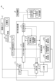
- FIG. 1 is a diagram showing a configuration example of a work system according to a first embodiment
- FIG. 4 is a diagram schematically showing an example of a method for acquiring environmental measurement data according to Embodiment 1
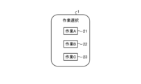
- a diagram showing an example of a work selection screen according to the first embodiment. 4 is a diagram showing an example of information received as work content by the input unit according to Embodiment 1
- FIG. FIG. 4 is a diagram showing a configuration example of a work setting unit and a robot motion calculation unit according to Embodiment 1;
- FIG. 11 is a diagram showing an example of multi-step batch motion calculation according to the first embodiment; A diagram showing an example of a trajectory generated by a process unit motion calculation and a trajectory generated by a multi-process batch motion calculation.
- 1 is a diagram showing a configuration example of a computer system that realizes the teaching support device according to Embodiment 1;
- FIG. FIG. 11 is a diagram showing a configuration example of a teaching support device according to a second embodiment;
- FIG. 10 is a diagram showing a configuration example of a work system according to a third embodiment;
- FIG. 11 is a diagram showing a configuration example of a work system according to a fourth embodiment;
- FIG. FIG. 11 is a diagram showing a configuration example of a work system according to a fifth embodiment;
- FIG. 1 is a diagram illustrating a configuration example of a work system according to a first embodiment
- a work system 6 of this embodiment includes a teaching support device 1 , an image sensor 2 , a robot control device 3 , a robot 4 and a sensor 5 .
- the work system 6 is a system that uses the robot 4 to perform work.
- the robot 4 is an example of a work machine, and may be, for example, an industrial robot that performs boxing, assembly, processing, transportation, packaging, etc., or a service robot that assists people. Further, the robot 4 may be an outdoor robot for agricultural work, construction work, or the like, or may be an indoor robot.
- the robot 4 is, for example, a multi-axis vertical articulated robot, but is not limited to this, and may be a linear motion robot or a robot combining linear motion and rotation. There are no restrictions on the type. In the following, an example in which the robot 4 is an industrial multi-axis vertical articulated robot will be described as an example.
- the robot control device 3 receives a robot motion command, which is a command relating to the motion of the robot, from the teaching support device 1, and sets a control amount for controlling the motors of the robot so that the robot 4 follows the received robot motion command.
- the operation of the robot 4 is controlled by calculating and outputting the control amount to the robot 4 .
- the robot control device 3 may correct the motion of the robot 4 using the detection result of the sensor 5 .
- the sensor 5 is a sensor that detects the position, posture, etc., of the work target of the robot 4, and is, for example, a two-dimensional or three-dimensional vision sensor.
- the robot control device 3 controls the motion of the robot 4 by driving motors (not shown) for each axis of the robot 4 .
- a general method can be used for the control in the robot control device 3, so a detailed description thereof will be omitted.
- the robot control device 3 is provided separately from the robot 4 in FIG. 1, the robot control device 3 may be included in the robot.
- the sensor 5 may be provided at a position different from that of the robot 4 or may be provided on the robot 4 .
- the image sensor 2 is a sensor that acquires a three-dimensional image, and acquires environmental measurement data by measuring the environment around the robot 4.
- Environmental measurement data is data obtained by imaging the environment with the image sensor 2 .
- the environment around the robot 4 is, for example, objects and structures in the area including the movable range of the robot 4 .
- the image sensor 2 is, for example, an RGB-D (Depth) sensor capable of obtaining a three-dimensional image by acquiring depth and color.
- the teaching support device 1 automatically generates an operation program corresponding to the work to be performed by the robot 4 based on the environmental measurement data from the image sensor 2 and the work content input by the user, and uses the operation program to perform the robot operation. A command is generated, and the generated robot operation command is transmitted to the robot control device 3 .
- the teaching support device 1 accepts the input of the work content itself by selecting it from a natural language or a video showing the work, so that even a user who is unfamiliar with programming can easily instruct the work content. It can be performed.
- the teaching support device 1 is, for example, a mobile terminal device such as a tablet, a smartphone, or a personal computer, but is not limited to a mobile terminal device.
- the teaching support device 1 includes a modeling section 11 , a robot motion calculation section 12 , a work information storage section 13 , a display section 14 , an input section 15 and a work setting section 16 .
- the modeling unit 11 acquires the environmental measurement data by receiving the environmental measurement data from the image sensor 2, and generates an environment model, which is a three-dimensional model of the environment, using the acquired environmental measurement data.
- the environment model is output to the display section 14 and the robot motion calculation section 12 .
- the modeling unit 11 generates an environment model by three-dimensional reconstruction that connects a plurality of partial three-dimensional data based on environmental measurement data, which is point cloud data, for example.
- the input unit 15 accepts input from the user.
- the input unit 15 receives input of work content from the user, and outputs the received work content (information indicating the work content) to the display unit 14 and the work setting unit 16 .
- the input unit 15 may receive the user's utterance as voice, or may receive the selection result selected by the user from options displayed on the display unit 14 .
- the input unit 15 includes a microphone (not shown) and a voice recognition unit that performs voice recognition processing.
- a microphone may be provided separately from the teaching support device 1 , and the voice acquired by the microphone may be input to the input unit 15 .
- the option When receiving a selection result selected by the user from the options displayed on the display unit 14, the option may be character information indicating a candidate for work content, or may be a moving image or an image.
- the input unit 15 receives a selection result by tapping, keyboard operation, mouse operation, or the like. Further, the input unit 15 may receive an input of work content or a selection result by image recognition of gestures or eye contact. When input is received by gesture or eye contact, the input unit 15 may have an imaging function, and an image captured by an imaging means different from the input unit 15 is input to the input unit 15. good too.
- the display unit 14 displays various information, images, videos, and the like. For example, the display unit 14 displays the work content received from the input unit 15 . Further, the display unit 14 displays the motion of the robot based on the environment model received from the modeling unit 11 and the robot model and the robot motion command (or information indicating the motion of the robot) received from the robot motion calculation unit 12 . Display by (Augmented Reality) display.
- the robot model may be stored in a model storage unit (not shown) of the teaching support device 1, and the display unit 14 may read the robot model from the model storage unit.
- the environment model may be stored in the model storage unit by the modeling unit 11 and read out from the model storage unit by the display unit 14 .
- the model storage unit may be provided outside the teaching support device 1 .
- the robot model to be used is designated by the robot motion calculation unit 12 or the work setting unit 16, and the display unit 14 is designated.
- the robot model that has been stored may be read from the model storage unit.
- the display unit 14 may be realized using hardware having a function of receiving input such as a touch panel.
- the display unit 14 may include a touch panel and a display data generation unit for performing AR display and the like, and the touch panel may have a part of the functions of the input unit 15 .
- an input from the user may be accepted by detecting that the user has tapped an image, character, or the like displayed on the touch panel.
- the work setting unit 16 converts the work content received from the input unit 15 into a programming language, and outputs work setting information including the conversion result to the robot motion calculation unit 12 .
- the work information storage unit 13 stores, for each work, a template indicating the motion of the robot 4 corresponding to the work in a work database (hereinafter referred to as work DB (Database)).
- the template defines the main part of the operation program corresponding to the work, and includes information indicating the operation corresponding to the operation program in natural language or animation.
- the work setting unit 16 causes the display unit 14 to display information indicating the templates.
- the information indicating the plurality of templates may be information indicating the operation of the work using characters, or may be identification information corresponding to the templates. Also, a moving image corresponding to the template may be displayed on the display unit 14 . Furthermore, the work setting unit 16 may cause the display unit 14 to display an explanatory moving image, an explanatory diagram, an explanatory text, etc. for each template.
- the display unit 14 displays, for example, information indicating the template as a pull-down menu, and the input unit 15 receives the input of the selection result.
- the input section 15 outputs the selection result to the work setting section 16 . It should be noted that the display method of the information indicating the template is not limited to this example.
- the work setting unit 16 acquires the work content corresponding to the template using the selection result of the template via the input unit 15, recognizes the work content based on the acquired input, and converts the recognized content into a programming language. do.
- the template shows an overview of typical work, and is created for each work such as boxing work, assembly work, and packaging work.
- boxing work the robot 4 grabs an object and packs it in a target location.
- the information indicates the action of "grabbing X, carrying it to Y, and packing it in Y.”
- X is the object and Y is the place to fill.
- the content of work is determined by inputting X and Y from the user.
- the model may also include the number of items to pack, such as "grab X, carry to Y, and pack Z items into Y.”
- the work information storage unit 13 stores work information related to work performed by the robot 4 as a work DB.
- the work information includes, for example, a model corresponding to each work described above and constraints for each model.
- the robot motion calculation unit 12 calculates the motion of the robot 4 while avoiding interference between the robot 4 and the environment, based on the work content input by the user and the environment model, which is a three-dimensional model that models the environment of the working machine. It is a motion calculation unit that generates a trajectory. Specifically, the robot motion calculation unit 12 uses the work setting information received from the work setting unit 16, the environment model received from the modeling unit 11, and the detection result of the sensor 5 to perform work according to the work content. is determined so that the robot 4 does not interfere with the environment. In FIG. 1 , the robot motion calculation unit 12 acquires the detection result of the sensor 5 via the robot control device 3 , but the detection result of the sensor 5 may be acquired from the sensor 5 .
- the trajectory of the robot 4 is determined by collectively treating work including a plurality of steps as one motion.
- the robot motion calculation unit 12 generates a robot motion command, which is a motion command for the robot 4 , based on the determined trajectory, and transmits the generated robot motion command to the robot control device 3 .
- FIG. 2 is a flow chart showing an example of a processing procedure in the teaching support device 1 of this embodiment.
- the teaching support device 1 determines whether or not there is an environment model (step S1). Specifically, the modeling unit 11 determines whether an environment model has already been generated.
- step S2 the teaching support device 1 generates an environment model (step S2) and advances the process to step S3.
- step S2 the modeling unit 11 generates an environment model by three-dimensional reconstruction using environmental measurement data acquired by the image sensor 2, for example.
- FIG. 3 is a diagram schematically showing an example of the environmental measurement data acquisition method according to the present embodiment.
- FIG. 3 shows an example in which the robot 4 is caused to perform the task of “packing fried chicken into a bento box.”
- the image sensor 2 is attached to the teaching support device 1, and the user operates the image sensor 2 via the teaching support device 1 or directly operates the image sensor 2 to
- the surroundings of the robot 4 are photographed from a plurality of locations. Thereby, a plurality of three-dimensional images photographed from a plurality of locations are acquired.
- the modeling unit 11 generates an environment model, which is a three-dimensional model of the environment, by performing three-dimensional reconstruction by joining these three-dimensional images.
- the environment model is represented by, for example, MESH, OBB (Oriented Bounding Box), polygons, etc.
- the representation format of the environment model is not limited to these, and any format may be used.
- 3D reconstruction is a technology that extracts feature points and planes from multiple partially captured environmental measurement data and connects them to generate an overall 3D model.
- an example of generating a three-dimensional model using environmental measurement data acquired by the image sensor 2, which is an RGB-D sensor, will be described.
- a three-dimensional model may be generated using a plurality of them.
- the robot 4 packs the fried chicken 32 stacked in the weight 31 into the target compartment 34, which is a compartment for packing the fried chicken 32, among the multiple compartments of the lunch box 33. conduct.
- the robot 4 performs this operation, in addition to the fried chicken 32 which is the object to be moved by the robot 4, a bento box 33, a weight 31, and a table (not shown) on which the weight 31 is placed are present in the surroundings. It is necessary to understand the environment, such as the object that moves, the surrounding structure, and so on.
- the teaching support device 1 of the present embodiment automatically generates an environment model by the user capturing an image of the surroundings with the image sensor 2 .
- the senor 5 is provided separately from the robot 4 for detecting the position and orientation of the fried chicken 32, which is the object. It may be attached to the robot 4 or may be attached to the robot 4 .
- the image sensor 2 is attached to the teaching support device 1, but the image sensor 2 is provided separately from the teaching support device 1, and the user carries the image sensor 2 around. You can take pictures.
- the teaching support device 1 may acquire the environmental measurement data by connecting it to the image sensor 2 by wire or wirelessly. Environmental measurement data may be read.
- environment measurement data is not limited to the example shown in FIG. good.
- environmental measurement data can be obtained by attaching the sensor 5 to the tip of the robot 4 or the like, operating the robot 4, and performing imaging with the image sensor 2. may be
- step S3 the teaching support device 1 accepts the selection of work.
- the work setting unit 16 causes the display unit 14 to display a template for each work (a template for each work type) stored in the work DB of the work information storage unit 13, and the input unit 15 displays the user's selection result. , and outputs the received selection result to the work setting unit 16 .
- the process of step S3 may not be performed.
- FIG. 4 is a diagram showing an example of the work selection screen according to this embodiment.
- buttons 21, 22, and 23 corresponding to each task are displayed, and the user selects the task by pressing the corresponding button.
- FIG. 4 is an example, and the contents of the work selection screen and the selection method are not limited to this example.
- the teaching support device 1 accepts an instruction for the content of the selected work (step S4).
- the work setting unit 16 outputs to the input unit 15 a template corresponding to the selection result selected in step S3.
- the input unit 15 receives an input from the user, determines the content of the selected work (work content) based on the input information and the template, and displays the determined work content on the display unit 14 and the work settings. Output to the unit 16 .
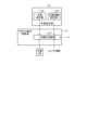
- FIG. 5 is a diagram showing an example of information received as work content by the input unit 15 of the present embodiment.
- work A is selected, and as a template for work A, an action of "grabbing X, carrying it to Y, and filling Y with Z pieces" is defined.
- the input unit 15 recognizes the detected voice by voice recognition using a template.
- the speech recognition may be general-purpose speech recognition, or may be used to recognize the work content of the robot 4, such as performing speech recognition using a trained model by machine learning specialized for the work content using the robot 4. It may be specialized processing.
- the input unit 15 causes the display unit 14 to display information prompting the input of the content when there is information that has not been input among X, Y, and Z or information that could not be recognized as a result of voice recognition. By doing so, the input of missing information is accepted. For example, if it is possible to recognize that X is "fried chicken” and Y is "lunch box” by detecting and recognizing the utterance "put fried chicken in a lunch box", the information of Z is Since it is insufficient, the display unit 14 is caused to display a question about the number of fried chicken. Instead of the display unit 14, a speaker may be used to present the question to the user by voice. Alternatively, audio may be presented to the user along with the display. In addition, when the lunch box is divided into a plurality of compartments, a question is presented to the user as to which compartment of the "lunch box" the fried chicken is to be packed in, prompting the user to enter the compartment.
- the input unit 15 is not limited to the example using the voice recognition described above, and displays information indicating options of X, Y, and Z on the display unit 14 as characters, images, etc., and by tapping and other selection operations, Inputs of X, Y, and Z may be accepted.
- the teaching support device 1 displays the work content (step S5). Specifically, the input unit 15 instructs the display unit 14 to display the work content received in step S4, and the display unit 14 displays the work content.
- the display unit 14 may display an AR motion of the robot corresponding to the work content. This allows the user to confirm whether the determined work content is desired. If the work content is not what is desired, the process from step S3 or the process of step S4 may be executed again.
- the teaching support device 1 calculates the robot motion from the work content and the environment model (step S6).
- the work setting unit 16 outputs work setting information including the result of converting the work contents into the operation program to the robot operation calculation unit 12 .
- the robot motion calculation unit 12 determines the trajectory of the robot using the work setting information received from the work setting unit 16 and the environment model received from the modeling unit 11 or read from a model storage unit (not shown). Generate robot motion commands based on the trajectory.
- the robot motion calculation unit 12 treats, for example, a plurality of motions corresponding to a plurality of processes constituting a work as one batch motion, and the start position and end position of the batch motion and constraints on the motion of the working machine. and conditions to generate motion trajectories. Note that the method of determining the trajectory of the robot motion calculation unit 12 is not limited to this example.
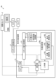
- FIG. 6 is a diagram showing a configuration example of the work setting unit 16 and the robot motion calculation unit 12 of this embodiment.
- the work setting section 16 includes a work designating section 161 and a target information setting section 162 .
- the work designation unit 161 generates an operation program corresponding to the work content received by the input unit 15 as work designation information for designating the work.
- the target information setting unit 162 generates target object information including information indicating, for example, the target object and the supply state, based on the work content.
- the target indicates the type of target, for example, fried chicken or screw.
- the supply state indicates how the objects are supplied, such as whether the objects are stacked and supplied or whether they are conveyed by a belt conveyor or the like.
- the supply state is, for example, predetermined for each object, and correspondence information indicating the correspondence between the object and the supply state is stored in the work DB.
- the object information setting unit 162 determines the supply state corresponding to the object by referring to the correspondence information in the work DB.
- correspondence information indicating the correspondence between the information and the object is similarly stored in the work DB.
- the information setting unit 162 may obtain the information using this correspondence information and include it in the target information.
- the robot motion calculation unit 12 outputs the work designation information generated by the work designation unit 161 and the target object information generated by the target information setting unit 162 to the robot motion calculation unit 12 as work setting information.
- the operation setting unit 16 generates an operation program for operating the robot 4
- the robot operation calculation unit 12 may generate the operation program.
- the robot motion calculation unit 12 includes a batch motion calculation unit 121 .
- the batch operation calculation unit 121 performs multi-step batch operation calculation using work designation information, target object information, and an environment model and sensor information (not shown in FIG. 6) to calculate separately for each step.
- a trajectory of the robot 4 whose operation time is shorter than that of the trajectory that is joined together is generated.
- FIG. 7 is a diagram showing an example of multi-step batch operation calculation according to the present embodiment.
- FIG. 7 shows an example in which the robot 4 performs the task of packing the fried chicken 32 stacked on the weight 31 into the target section 34 of the lunch box 33 .
- this work consists of process #1 in which the robot 4 takes out the fried chicken 32 from the weight 31, and the robot 4 takes out the fried chicken 32 from the weight 31 to the lunch box 33. It includes a step #2 which is a step of carrying, and a step #3 which is a step of packing the fried chicken 32 into the target section 34 of the lunch box 33 by the robot 4. ⁇
- a trajectory that does not interfere with the environment by a step-by-step motion calculation, which is a calculation for optimizing the motion of the robot 4 for each step.
- the collective motion calculation unit 121 shown in FIG. A trajectory that shortens the operation time is generated after considering constraints (orientation of the trajectory and movement speed).
- the robot motion calculation unit 12 may generate a trajectory that does not interfere with the environment by the process unit motion calculation.
- FIG. 8 is a diagram showing an example of a trajectory generated by a process unit motion calculation and a trajectory generated by a multi-process batch motion calculation.
- the upper part of FIG. 8 shows an example of a trajectory generated by the process unit motion calculation.
- the motions #1 to #4 corresponding to the process #1 shown in FIG.
- Trajectories of motions #5 and #6 corresponding to #2 and motion #7 corresponding to process #3 shown in FIG. 7 are generated.
- Motions #1 to #3 are motions in which the robot 4 starts to move toward the weight 31, but the motions of the robot 4 are slowed down due to motion restrictions near the start and stop of the motions.
- Operation #2 is a high-speed operation.
- Operation #4 is an operation of closing a hand, which is a gripping portion provided at the tip of the robot 4 . It is assumed that the hand is open at the start of work. Action #5 is a low-speed action to start moving to the lunch box 33, and action #6 is a high-speed action to move to the lunch box 33. By opening the hand in operation #7, the fried chicken 32 is packed in the target section 34 of the lunch box 33. - ⁇ Note that the operation in FIG. 8 is an example, and the specific operation is not limited to the example shown in FIG.
- the target position of the robot 4 is determined based on sensor information.
- an optimum trajectory is generated for each process based on the target position and the environment model.
- the optimum trajectory is, for example, a trajectory that minimizes the evaluation function under the constraint conditions and that does not interfere with the environment.
- the optimum trajectory is not limited to the trajectory that minimizes the evaluation function, and may be the trajectory that makes the evaluation function equal to or less than the threshold.
- the evaluation function is, for example, at least one of the working time of the robot 4, the power consumption of the robot 4, the moving distance of the robot 4, and the like. Constraints are constraints on the speed and movement direction of the robot, and are stored in the work DB.
- the collective motion calculation unit 121 calculates an optimal trajectory for motion A.
- FIG. That is, the batch motion calculation unit 121 integrates motions #1 to #3 as motion A, and uses sensor information, object information, and speed constraint conditions to determine one trajectory whose evaluation function is equal to or less than the threshold. Generate.
- the collective motion calculation unit 121 generates a trajectory using speed constraints with reference to the remaining distance.
- the batch motion calculator 121 similarly integrates motions #5 and #6 as motion B to generate one trajectory.
- the teaching support device 1 displays the robot motion (step S7).
- the robot motion calculation unit 12 outputs information indicating the robot motion corresponding to the generated trajectory (motion trajectory) to the display unit 14, and the display unit 14 displays the motion of the robot 4 corresponding to the motion trajectory.
- the display unit 14 can display the robot motion in AR by displaying the robot model in a desired posture based on input of joint angle information, which is motion commands at each moment. This allows the user to confirm whether the determined robot motion is the desired one. If the robot motion is not desired, the process from step S3 or step S4 may be performed again.
- the teaching support device 1 transmits a robot operation command to the robot control device 3 (step S8), and ends the process. Specifically, in step S ⁇ b>8 , the robot motion calculation unit 12 transmits the robot motion command generated in step S ⁇ b>7 to the robot control device 3 .
- the robot motion calculation unit 12 temporarily stops the sensor 5 above the gripped object, The position of the target object and the like may be recognized by capturing the image and acquiring the sensor information.
- the sensor 5 is attached to the robot 4, the sensor 5 also moves along with the motion of the robot 4, and blurring occurs during photographing.
- the sensor 5, which is a three-dimensional sensor is fixed above the object, the robot 4 is not stopped above the object to be grasped, and after the object has been grasped and the object has been passed through the area to be grasped, the sensor 5 may be imaged and the sensor information may be acquired to recognize the position of the target object.
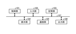
- FIG. 9 is a diagram showing a configuration example of a computer system that implements the teaching support device 1 of this embodiment.
- this computer system comprises a control section 101, an input section 102, a storage section 103, a display section 104, a communication section 105 and an output section 106, which are connected via a system bus 107.
- control unit 101 is, for example, a processor such as a CPU (Central Processing Unit), and executes a program in which processing in the teaching support device 1 of the present embodiment is described.
- a part of the control unit 101 may be implemented by dedicated hardware such as a GPU (Graphics Processing Unit) or an FPGA (Field-Programmable Gate Array).
- the input unit 102 is composed of, for example, a keyboard and a mouse, and is used by the user of the computer system to input various information.
- Input unit 102 may include a microphone.
- the storage unit 103 includes various memories such as RAM (Random Access Memory) and ROM (Read Only Memory) and storage devices such as hard disks, and stores programs to be executed by the control unit 101 and necessary information obtained in the process of processing.
- the storage unit 103 is also used as a temporary storage area for programs.
- the display unit 104 includes a display, LCD (liquid crystal display panel), etc., and displays various screens to the user of the computer system. Also, the display unit 104 may be a touch panel having a function as the input unit 102 .
- a communication unit 105 is a receiver and a transmitter that perform communication processing.
- the output unit 106 is a printer, speaker, or the like. Note that FIG. 9 is an example, and the configuration of the computer system is not limited to the example in FIG.
- a computer program is stored in a storage unit from a CD-ROM or DVD-ROM set in a CD (Compact Disc)-ROM drive or a DVD (Digital Versatile Disc)-ROM drive (not shown).
- 103 installed.
- the program read from storage unit 103 is stored in the main storage area of storage unit 103 .
- the control unit 101 executes processing as the teaching support device 1 of this embodiment according to the program stored in the storage unit 103 .
- a recording medium such as a CD-ROM or a DVD-ROM is used to provide a program describing the processing in the teaching support device 1.
- a program provided via a transmission medium such as the Internet via the communication unit 105 may be used depending on the capacity of the program to be provided.
- the teaching support program of the present embodiment includes, for example, a step of acquiring a work content input by a user and an environment model, which is a three-dimensional model of the environment of a work machine, and a step of acquiring the work content and the environment model. and generating a motion trajectory of the work machine that avoids interference between the work machine and the environment.
- the modeling unit 11, the robot motion calculation unit 12, and the work setting unit 16 shown in FIG. 1 are executed by the control unit 101 shown in FIG. Realized.
- the storage unit 103 shown in FIG. 9 is also used to realize the modeling unit 11, the robot motion calculation unit 12, and the work setting unit 16 shown in FIG.
- the work information storage unit 13 shown in FIG. 1 is a part of the storage unit 103 shown in FIG.
- Display unit 14 shown in FIG. 1 is realized by display unit 104 and control unit 101 shown in FIG.
- Input unit 15 shown in FIG. 1 is realized by input unit 102 and control unit 101 shown in FIG. Further, when the input unit 15 receives input by voice, the input unit 102 may include a microphone, or an external microphone may be used.
- the teaching support device 1 may be realized by a plurality of computer systems.
- the input unit 15, the display unit 14, and the work setting unit 16 shown in FIG. may be implemented.
- components other than the robot motion calculation unit 12 may be implemented by a computer system such as a tablet, and the robot motion calculation unit 12 may be implemented by another computer system.
- the robot control device 3 may include some of the functional units of the teaching support device 1 shown in FIG.
- the teaching support device 1 may be realized by a cloud computer system.
- the teaching support device 1 generates an environment model based on environmental measurement data acquired by the image sensor 2, but the environment model is generated as a CAD (Computer Aided Design) model or the like. environment model may be input from the outside.
- the teaching support device 1 receives an environment model from another device (not shown), and the environment model is input to the robot motion calculation unit 12 and the display unit 14 .
- the work system 6 does not need to include the image sensor 2 and the teaching support device 1 does not need to include the modeling section 11 .
- the teaching support device 1 shown in FIG. 1 further has a function of inputting an externally input environment model to the robot operation calculation unit 12 and the display unit 14, and the environment model based on the environment measurement data, You may enable it to utilize both the created environment model.
- the teaching support device 1 of the present embodiment accepts input of work details from the user and automatically generates an operation program based on the accepted work details.
- a program for each work is registered as template information in the work DB, and a person corresponding to the work is loaded into the robot motion calculation unit 12 .
- the robot motion calculation unit 12 provides the loaded program with information on the size of the work area and the position of the work area related to the work task.
- the program is configured so that the necessary teaching point setting and trajectory generation of the program loaded from the template can be automatically performed. That is, no user input is required to specify the robot motion. Therefore, by designating only information such as the size of the work area, the position of the work area, and the work target, the robot can be moved.
- the teaching support device 1 of the present embodiment automatically generates an environment model using environmental measurement data acquired by the image sensor 2, and determines a trajectory of the robot that does not interfere with the environment using the generated environment model. Therefore, the time required to create the environment model can be shortened compared to the case where the user creates the environment model itself.
- the teaching support device 1 of the present embodiment since the teaching support device 1 of the present embodiment generates the trajectory of the robot 4 by treating a plurality of steps constituting a work as one operation, the operation time of the robot can be shortened. Adjustment time can be shortened.
- the teaching support device 1 creates a template corresponding to each task in advance, and presents information indicating the template corresponding to the task to the user, so that even an inexperienced user can perform the task. Content can be entered easily.
- the user can select a more appropriate template (work).
- FIG. 10 is a diagram illustrating a configuration example of a teaching support device according to a second embodiment;
- a teaching support device 1a of the present embodiment is the same as the teaching support device 1 of the first embodiment except that the modeling unit 11 is removed from the teaching support device 1 shown in FIG. 1 and the simulation unit 17 is added.
- Components having functions similar to those of the first embodiment are denoted by the same reference numerals as those of the first embodiment, and overlapping descriptions are omitted. Differences from the first embodiment will be mainly described below.
- the simulation unit 17, which is a simulator, performs a simulation that simulates the motion of the robot 4.
- the simulation result can be used for preliminary examination before actually installing the robot 4 .
- the setting of the work content when performing the simulation and the processing of the robot motion calculation unit 12 are the same as in the first embodiment.
- the environment model created as a CAD model is input to the robot motion calculation unit 12 .
- the robot motion calculation unit 12 outputs the robot motion command, the robot model, and the environment model to the simulation unit 17 .
- the simulation unit 17 performs a simulation simulating the motion of the robot 4 using the motion trajectory determined by the robot motion calculation unit 12 and the environment model. For example, it performs a simulation for simulating the motion of the robot 4 using the robot motion command, the robot model, and the environment model received from the robot motion calculation unit 12 and outputs the simulation result, which is the result of the simulation, to the display unit 14 .
- the display unit 14 displays the simulation results.
- the display unit 14 may display a visual programming screen, or may display the visual programming screen and the simulation results in a superimposed manner.
- the visual programming screen is, for example, a screen for specifying actions by arranging blocks.
- a simple programming language for block programming such as "Scratch” can be used. is not limited to this example.
- FIG. 11 is a diagram showing an example of the display screen of this embodiment.
- the simulation result is displayed on the teaching support device 1a.
- the visual programming screen is superimposed and displayed.
- FIG. 11 is an example, and the specific display screen is not limited to the example shown in FIG.
- the visual programming screen it is possible to accept inputs such as changes to sensors and robots, and changes to the placement of sensors and robots may be accepted, for example, on the screen where the simulation results are displayed. For example, by selecting and moving the part where the robot is displayed, the change of the placement of the robot may be accepted. These changes are accepted by the input unit 15 and the accepted results are output to the work setting unit 16 .
- a template list is displayed as a work item list, and when the user selects a work, the robot, hand, and sensor presets corresponding to the selected work are displayed.
- a robot list (various types of robots) and a sensor list (vision sensor, force sensor, tactile sensor, distance measurement sensor, etc.) are displayed, and you can tap and drag the element you want to add from these lists to the screen. It may be possible to make changes and additions in When a sensor is added, the physical quantity val (contact force with the environment, position of the object, distance between specified points) measured by the sensor is defined.
- the simulation unit 17 uses the defined physical quantity val as an input, the simulation unit 17 checks the feasibility of operation based on the operation conditions of the block programming, and displays the simulation result as a moving image on the display unit 14 . For example, when an object is moving on a conveyor, if the position of the vision sensor that detects the position of the object is too close to the robot, problems such as the recognition time being delayed may occur. An appropriate positional relationship can be considered in advance by simulating.
- the display unit 14 displays a screen for performing block programming
- the input unit 15 receives an input for changing the robot in the block programming
- the robot operation calculation unit 12 receives the input unit 15.
- the trajectory may be generated reflecting the input.
- an input for adding or changing a sensor used for determining the motion of the robot may be received, and the robot motion calculation unit 12 may generate a trajectory by reflecting the input received by the input unit 15 .
- FIG. 10 shows the functional configuration for performing simulation
- the teaching support apparatus 1a having the configuration shown in FIG. A simulation unit 17 may be added to the device 1 so that both the operation described in the first embodiment and the simulation can be performed.
- the hardware configuration of the teaching support device 1a of the present embodiment is the same as that of the teaching support device 1 of the first embodiment.
- the simulation unit 17 is realized by executing a computer program stored in the storage unit 103 shown in FIG. 9 by the control unit 101 shown in FIG.
- the storage unit 103 shown in FIG. 9 is also used for realizing the simulation unit 17 .
- the teaching support device 1a may be composed of a plurality of computer systems.
- the teaching support device 1a is provided with a modeling unit 11, the modeling unit 11 generates an environment model using environmental measurement data, and the simulation unit 17 is generated.
- a simulation may be performed using an environment model.
- the teaching support device 1a is configured to perform a simulation that simulates the motion of the robot, so the simulation results can be used for prior examination.
- FIG. 12 is a diagram illustrating a configuration example of a work system according to a third embodiment;
- the work system 6b of the present embodiment is the same as the work system 6 of the first embodiment except that the teaching support device 1b is provided instead of the teaching support device 1.
- FIG. Components having functions similar to those of the first embodiment are denoted by the same reference numerals as those of the first embodiment, and overlapping descriptions are omitted. Differences from the first embodiment will be mainly described below.
- the teaching support device 1b is the same as the teaching support device 1 of Embodiment 1 except that it includes a modeling unit 11a, an input unit 15a and a work setting unit 16a instead of the modeling unit 11, the input unit 15 and the work setting unit 16. be.
- the work setting unit 16a is the same as the work setting unit 16 of Embodiment 1, except that a motion correction unit 163 is added.
- the teaching support device 1b of the present embodiment receives corrections of at least one of the environment model and the actions of the robot 4 in addition to the same actions as in the first embodiment, and reflects the corrections.
- FIG. 13 is a flow chart showing an example of a processing procedure in the teaching support device 1b of this embodiment. Steps S1 to S7 are the same as in the first embodiment.
- step S9 the teaching support device 1b determines whether or not there is a correction instruction. Specifically, the input unit 15a determines whether or not an instruction to modify at least one of the environment model and the motion of the robot 4 has been received from the user. If there is a correction instruction (step S9 Yes), the teaching support device 1b corrects the robot motion (step S10) and advances the process to step S8. If there is no correction instruction (step S9 No), the teaching support device 1b advances the process to step S8. Step S8 is the same as in the first embodiment.
- the trajectory of the robot 4 displayed in step S7 is a trajectory that is considered to be a threat to the worker collaborating with the robot 4, at least a part of the prohibited area and the permitted area is set to the input unit 15a.
- the display unit 14 is a touch panel that also has a part of the functions of the input unit 15a, the user can tap the position of at least one of the prohibited area model and the permitted area while the environment is being displayed.
- the specification specifies at least one of a prohibited area model and a permitted area model.
- the input unit 15a outputs at least one of the input prohibited area model and allowed area model to the modeling unit 11a.
- the modeling unit 11a modifies the environment model by adding at least one of the prohibited area model and the permitted area model, and displays the modified environment model on the display unit 14 and the robot motion calculation. Output to the unit 12 .
- the robot motion calculation unit 12 uses the modified environment model to perform the robot motion calculation in the same manner as in the first embodiment. That is, the robot motion calculation unit 12 generates a trajectory that reflects the correction instruction received by the input unit 15a. Specifically, when the prohibited area model is added, the robot motion calculation unit 12 determines the trajectory so that the robot 4 does not pass through the prohibited area in addition to the condition of not interfering with the environment. Further, when the permitted area model is added, the robot motion calculation unit 12 determines the trajectory under the condition that the robot 4 can pass within the permitted area even if it interferes with the environment.
- the user sets the prohibited area to an area where workers collaborating with the robot 4 feel threatened.
- the permitted area near the object may be automatically set using sensor information acquired by the sensor 5 .
- the modeling unit 11a may use the sensor information to automatically add the area around the object indicated by the sensor information as the allowed area model.
- the display unit 14 displays a button or the like for increasing the size of a partial model selected by the user from among the environment models from the original size, and the input unit 15a responds when the button is pressed.
- the modeling unit 11a may be instructed to enlarge the selected partial model.
- the modeling unit 11a increases the size of the partial model selected by the user according to a predetermined rule based on the instruction from the input unit 15a.
- a predetermined rule may be a rule that increases the size by a fixed amount in a particular direction or in all directions, or a rule that increases the size in a particular direction or in all directions by multiplying the size by a real number factor of 1 or more. It may be made larger, or the size may be increased by other methods. This creates a trajectory with a margin of distance from the actual environment.
- the input unit 15a accepts the user's utterance as voice and recognizes the correction target and the correction content, such as "Take P a little to the right," as the correction content of the motion of the robot 4. may be recognized.
- the input unit 15a outputs the voice recognition result to the work setting unit 16a, and the work setting unit 16a corrects the operation program according to the content of correction.
- items to be corrected such as the target position of the motion of the robot 4
- options may be presented to the user
- input of selection results may be accepted, and correction details of the item may be accepted by voice.
- the input unit 15 a may receive an input of a change in the constraint conditions of the motion of the robot 4 as the modification of the motion of the robot 4 .
- the correction contents of the motion of the robot 4 are output to the robot motion calculation unit 12 via the work setting unit 16a, and the robot motion calculation unit 12 reflects the correction to generate a trajectory.
- the display unit 14 displays buttons for instructing changes in the AR display speed, temporary stop of the AR display operation, and the like. Instructions for display may be received.
- the input unit 15a notifies the display unit 14 of the received instruction, and the display unit 14 controls the AR display according to the notification.
- the user can slow down the speed and check it in detail, or stop it and check it in detail.
- a correction function is added to the configuration example shown in FIG. 1, but the correction function may be added when using a generated environment model. Also, the function of executing the simulation described in the second embodiment may be added to the teaching support device 1b of the present embodiment.
- the hardware configuration of the teaching support device 1b of the present embodiment is the same as that of the teaching support device 1 of the first embodiment. Also, as in the first embodiment, the teaching support device 1b may be composed of a plurality of computer systems.
- FIG. 14 is a diagram illustrating a configuration example of a work system according to a fourth embodiment.
- the work system 6c of the present embodiment is the same as the work system 6b of the third embodiment except that the teaching support device 1c is provided instead of the teaching support device 1b and the analysis device 7 is added.
- Components having functions similar to those of the third embodiment are denoted by the same reference numerals as those of the third embodiment, and overlapping descriptions are omitted. Differences from the third embodiment will be mainly described below.
- a teaching support device 1c of the present embodiment has a transmitting/receiving unit 18 added to the teaching support device 1b of the third embodiment.
- the work setting unit 16a stores the work setting information in the work DB of the work information storage unit 13, so that the work DB stores settings such as work (type of work), target object, target area, etc., related to the set work. Information is stored.
- the robot motion calculation unit 12 outputs motion information, which is information related to robot motion such as a robot motion command, to the transmission/reception unit 18 .
- the transmitting/receiving unit 18 reads the setting information from the work DB, and transmits the read setting information and the motion information received from the robot motion calculation unit 12 to the analysis device 7 .
- the analysis device 7 includes a transmission/reception section 71 and an analysis section 72 .
- the transmitting/receiving unit 71 receives setting information and operation information from the teaching support device 1c, receives measurement information from the peripheral device 8, and receives success/failure information indicating the success or failure of work from the teaching support device 1c or another device.
- the obtained information is output to the analysis unit 72 .
- the success/failure information may be received by the input unit 15a of the teaching support device 1c from the user and transmitted to the analysis device 7 by the transmission/reception unit 18, or may be received by another device (not shown) from the user. may be transmitted to the analysis device 7 by Further, the transmission/reception unit 71 transmits the analysis result received from the analysis unit 72 to the teaching support device 1c.
- the analysis unit 72 uses the setting information, the operation information, the measurement information, and the success/failure information to analyze the factors that are likely to cause failure, and outputs the analysis results to the transmission/reception unit 71 .
- the peripheral device 8 is, for example, a sensor that detects the state of the robot 4, and is various sensors such as a temperature sensor, a motor speed sensor, and a vibration sensor attached to at least one of the robot 4 and the environment.
- the analysis device 7 receives the measurement information directly from the peripheral device 8, but the analysis device 7 receives the measurement information via the robot control device 3 or the teaching support device 1c. Alternatively, the measurement information may be received via another device (not shown).
- the analysis unit 72 classifies, for example, input information composed of setting information, operation information, measurement information, and success/failure information into groups with the same work content or groups with similar work content.
- the analysis unit 72 determines whether each item of the operation information and the measurement information exceeds the normal range for each group, and stores the correspondence between the normal range determination result and the success/failure information.
- the analysis unit 72 expresses average behavior as a regression model from data acquired when performing a certain task, and obtains in advance a region (normal range) distributed during normal operation. It may be judged as an abnormality by evaluating how much it deviates from it.
- the normal range is statistically defined as normal if it is within 3 ⁇ , and abnormal if it is more than 3 ⁇ , based on the feature value (for example, how much the sensor output deviates from the normal value) and its variance when it is tried multiple times. can do.
- the analysis unit 72 determines that the determination result corresponding to the input information indicating that the success/failure information indicates failure deviates from the normal range, and the determination result corresponding to the input information indicating that the success/failure information indicates success. is within the normal range, and the extracted items are determined as information corresponding to the influencing factor.
- the measurement information of sensor K corresponds to the influencing factor.
- the measurement information of sensor K corresponds to the influencing factor. be informational. For example, if sensor K is the temperature of part P of robot 4, part P is likely to be the influencing factor of the failure.
- the analysis unit 72 may determine the item as information corresponding to the influence factor. In addition, using the accumulated input information, the analysis unit 72 determines the normal range of each item by machine learning such as cluster analysis using the input information when the success/failure information indicates success or a statistical method. may Further, the analysis device 7 may perform analysis using information acquired from a plurality of teaching support devices 1c.
- the analysis unit 72 acquires information indicating the type of failure (details of failure) in the event of failure as success/failure information, and in the event of failure, the operator or the like checks the robot 4 to determine the location of the cause.
- machine learning may be performed using the identified locations as correct data.
- the analysis unit 72 generates a learned model through supervised learning using multiple data sets each including a type of failure and factors (parts serving as factors) that are the corresponding correct data.
- the analysis unit 72 may infer factors by inputting the type of failure into the learned model.
- At least one of the above-described input information may be used as input data to generate a trained model, or at least one of the above-described input information may be used as input data to generate a trained model.
- Other examples include the following.
- an operator intentionally causes a specific abnormal state, and the data of the output of each device and the error signal at that time are collected multiple times.
- time-series data of each signal or information graphed from time-series data is input and machine learning is performed.
- the abnormal state may be determined while collecting information or after collecting information.
- the system in particular, in the case of collecting information online, it is possible to obtain the effect that the system can be stopped in advance before the system fails if a somewhat similar abnormal state occurs.
- Further examples include the following.
- data obtained from multiple mechanical systems are collected in a server, and supervised based on a database containing at least one of the output of each sensor, error signal, and condition monitoring signal labeled with abnormal states.
- the analysis method of the analysis unit 72 described above is an example, and the analysis method of the analysis unit 72 is not limited to the example described above. Also, the information used for analysis by the analysis unit 72 is not limited to the above example.
- the transmission/reception unit 18 of the teaching support device 1c Upon receiving the analysis result from the analysis device 7, the transmission/reception unit 18 of the teaching support device 1c outputs the analysis result to the display unit 14, and the display unit 14 displays the analysis result.
- the teaching support device 1c transmits, for example, at least one of the information indicating the work content and the motion information to the analysis device 7, and the analysis device 7 detects the state of the robot 4.
- the analysis device 7 uses the information obtained from the sensor, the information indicating the content of the work, and the success/failure information indicating the success or failure of the work, the causes of the failure of the work are analyzed.
- the analysis result is transmitted to the teaching support device 1c.
- the display unit 14 of the teaching support device 1 c displays the analysis results received from the analysis device 7 .
- the user can grasp the analysis results displayed on the display unit 14, that is, the presumed factors, and try to take some action on the corresponding points. As a result, it is possible to facilitate recovery from the failure.
- the hardware configuration of the teaching support device 1c of the present embodiment is the same as that of the teaching support device 1 of the first embodiment. Moreover, as in the first embodiment, the teaching support device 1c may be composed of a plurality of computer systems.
- the analysis device 7 of the present embodiment is also implemented by a computer system as illustrated in FIG. 9 of the first embodiment.
- the analysis device 7 may be constructed on a cloud system.
- the teaching support device 1 described in Embodiment 1 may transmit information to the analysis device 7, acquire analysis results from the analysis device 7, and display them.
- FIG. 15 is a diagram of a configuration example of a work system according to a fifth embodiment;
- the working system 6d of the present embodiment is the same as the working system 6 of the first embodiment except that the teaching support device 1d is replaced with the teaching support device 1d.
- Components having functions similar to those of the first embodiment are denoted by the same reference numerals as those of the first embodiment, and overlapping descriptions are omitted. Differences from the first embodiment will be mainly described below.
- a teaching support device 1d of the present embodiment is the same as the teaching support device 1 of Embodiment 1 except that it includes a setting information acquisition unit 19 instead of the work setting unit 16 and the input unit 15.
- the setting information acquisition unit 19 of the teaching support device 1d receives the same work setting information as the work setting information output by the work setting unit 16 of the first embodiment to the robot motion calculation unit 12 from another device (not shown), It outputs the received work setting information to the robot motion calculation unit 12 .
- the teaching support device 1d receives the work setting information from the other teaching support device. to receive The teaching support device 1d of the present embodiment can thereby reduce the user's load.
- the hardware configuration of the teaching support device 1d of the present embodiment is the same as that of the teaching support device 1 of the first embodiment. Also, as in the first embodiment, the teaching support device 1d may be configured with a plurality of computer systems.
Landscapes
- Engineering & Computer Science (AREA)
- Human Computer Interaction (AREA)
- Manufacturing & Machinery (AREA)
- Physics & Mathematics (AREA)
- General Physics & Mathematics (AREA)
- Automation & Control Theory (AREA)
- Robotics (AREA)
- Mechanical Engineering (AREA)
- Manipulator (AREA)
- Numerical Control (AREA)
Priority Applications (4)
| Application Number | Priority Date | Filing Date | Title |
|---|---|---|---|
| PCT/JP2022/007996 WO2023162164A1 (ja) | 2022-02-25 | 2022-02-25 | 教示支援装置、作業システム、教示支援方法および教示支援プログラム |
| JP2022566474A JP7506180B2 (ja) | 2022-02-25 | 2022-02-25 | 教示支援装置、作業システム、教示支援方法および教示支援プログラム |
| DE112022006723.3T DE112022006723T5 (de) | 2022-02-25 | 2022-02-25 | Lehrunterstützungsvorrichtung, arbeitssystem, lehrunterstützungsverfahren und speichermedium |
| CN202280091947.0A CN118715492A (zh) | 2022-02-25 | 2022-02-25 | 示教辅助装置、作业系统、示教辅助方法及示教辅助程序 |
Applications Claiming Priority (1)
| Application Number | Priority Date | Filing Date | Title |
|---|---|---|---|
| PCT/JP2022/007996 WO2023162164A1 (ja) | 2022-02-25 | 2022-02-25 | 教示支援装置、作業システム、教示支援方法および教示支援プログラム |
Publications (1)
| Publication Number | Publication Date |
|---|---|
| WO2023162164A1 true WO2023162164A1 (ja) | 2023-08-31 |
Family
ID=87765139
Family Applications (1)
| Application Number | Title | Priority Date | Filing Date |
|---|---|---|---|
| PCT/JP2022/007996 Ceased WO2023162164A1 (ja) | 2022-02-25 | 2022-02-25 | 教示支援装置、作業システム、教示支援方法および教示支援プログラム |
Country Status (4)
| Country | Link |
|---|---|
| JP (1) | JP7506180B2 (https=) |
| CN (1) | CN118715492A (https=) |
| DE (1) | DE112022006723T5 (https=) |
| WO (1) | WO2023162164A1 (https=) |
Cited By (1)
| Publication number | Priority date | Publication date | Assignee | Title |
|---|---|---|---|---|
| JP7588927B1 (ja) * | 2024-01-05 | 2024-11-25 | リバーフィールド株式会社 | ロボット動作生成支援装置、ロボット動作生成支援システム、及びロボット動作生成支援プログラム |
Families Citing this family (1)
| Publication number | Priority date | Publication date | Assignee | Title |
|---|---|---|---|---|
| WO2026034638A1 (ja) * | 2024-08-09 | 2026-02-12 | 川崎重工業株式会社 | 動作プログラム生成システム |
Citations (9)
| Publication number | Priority date | Publication date | Assignee | Title |
|---|---|---|---|---|
| JP2011230245A (ja) * | 2010-04-28 | 2011-11-17 | Yaskawa Electric Corp | ロボットシステム |
| JP2018069377A (ja) * | 2016-10-28 | 2018-05-10 | ファナック株式会社 | ロボットが行う物品整列作業のシミュレーションのための装置、方法、プログラム及び記録媒体 |
| JP2018134703A (ja) * | 2017-02-21 | 2018-08-30 | 株式会社安川電機 | ロボットシミュレータ、ロボットシステム及びシミュレーション方法 |
| JP2019093492A (ja) * | 2017-11-24 | 2019-06-20 | ファナック株式会社 | ロボットに対して教示操作を行う教示装置 |
| JP2020006472A (ja) * | 2018-07-06 | 2020-01-16 | ファナック株式会社 | ロボットプログラム生成装置 |
| US20200230817A1 (en) * | 2017-02-03 | 2020-07-23 | Doosan Robotics Inc | Skill-based robot programming apparatus and method |
| WO2020149021A1 (ja) * | 2019-01-15 | 2020-07-23 | オムロン株式会社 | 経路生成装置、経路生成方法、及び経路生成プログラム |
| JP2021003736A (ja) * | 2019-06-25 | 2021-01-14 | ファナック株式会社 | ロボットプログラミング装置 |
| WO2021245746A1 (ja) * | 2020-06-01 | 2021-12-09 | ファナック株式会社 | ロボットのプログラミング装置 |
Family Cites Families (1)
| Publication number | Priority date | Publication date | Assignee | Title |
|---|---|---|---|---|
| CN110536783B (zh) | 2017-04-19 | 2022-06-14 | 株式会社安川电机 | 编程支持装置、机器人系统、编程支持方法以及存储介质 |
-
2022
- 2022-02-25 CN CN202280091947.0A patent/CN118715492A/zh active Pending
- 2022-02-25 DE DE112022006723.3T patent/DE112022006723T5/de active Pending
- 2022-02-25 WO PCT/JP2022/007996 patent/WO2023162164A1/ja not_active Ceased
- 2022-02-25 JP JP2022566474A patent/JP7506180B2/ja active Active
Patent Citations (9)
| Publication number | Priority date | Publication date | Assignee | Title |
|---|---|---|---|---|
| JP2011230245A (ja) * | 2010-04-28 | 2011-11-17 | Yaskawa Electric Corp | ロボットシステム |
| JP2018069377A (ja) * | 2016-10-28 | 2018-05-10 | ファナック株式会社 | ロボットが行う物品整列作業のシミュレーションのための装置、方法、プログラム及び記録媒体 |
| US20200230817A1 (en) * | 2017-02-03 | 2020-07-23 | Doosan Robotics Inc | Skill-based robot programming apparatus and method |
| JP2018134703A (ja) * | 2017-02-21 | 2018-08-30 | 株式会社安川電機 | ロボットシミュレータ、ロボットシステム及びシミュレーション方法 |
| JP2019093492A (ja) * | 2017-11-24 | 2019-06-20 | ファナック株式会社 | ロボットに対して教示操作を行う教示装置 |
| JP2020006472A (ja) * | 2018-07-06 | 2020-01-16 | ファナック株式会社 | ロボットプログラム生成装置 |
| WO2020149021A1 (ja) * | 2019-01-15 | 2020-07-23 | オムロン株式会社 | 経路生成装置、経路生成方法、及び経路生成プログラム |
| JP2021003736A (ja) * | 2019-06-25 | 2021-01-14 | ファナック株式会社 | ロボットプログラミング装置 |
| WO2021245746A1 (ja) * | 2020-06-01 | 2021-12-09 | ファナック株式会社 | ロボットのプログラミング装置 |
Cited By (2)
| Publication number | Priority date | Publication date | Assignee | Title |
|---|---|---|---|---|
| JP7588927B1 (ja) * | 2024-01-05 | 2024-11-25 | リバーフィールド株式会社 | ロボット動作生成支援装置、ロボット動作生成支援システム、及びロボット動作生成支援プログラム |
| WO2025146716A1 (ja) * | 2024-01-05 | 2025-07-10 | リバーフィールド株式会社 | ロボット動作生成支援装置、ロボット動作生成支援システム、及びロボット動作生成支援プログラム |
Also Published As
| Publication number | Publication date |
|---|---|
| CN118715492A (zh) | 2024-09-27 |
| DE112022006723T5 (de) | 2024-12-19 |
| JP7506180B2 (ja) | 2024-06-25 |
| JPWO2023162164A1 (https=) | 2023-08-31 |
Similar Documents
| Publication | Publication Date | Title |
|---|---|---|
| JP6886869B2 (ja) | 動作予測システム及び動作予測方法 | |
| US10706331B2 (en) | Task execution system, task execution method, training apparatus, and training method | |
| US11850755B2 (en) | Visualization and modification of operational bounding zones using augmented reality | |
| US11331803B2 (en) | Mixed reality assisted spatial programming of robotic systems | |
| CN113703569B (zh) | 用于工业自动化的虚拟现实和增强现实的系统和方法 | |
| US9149931B2 (en) | Robot system, robot control device and method for controlling robot | |
| JP6863927B2 (ja) | ロボットのシミュレーション装置 | |
| US12579468B2 (en) | Training data screening device, robot system, and training data screening method | |
| JP2019188530A (ja) | ロボットのシミュレーション装置 | |
| JP2003117863A (ja) | ロボットシミュレーション装置 | |
| KR102567361B1 (ko) | 로봇 교시 장치 및 이를 이용한 로봇 교시 방법 | |
| JP7601215B2 (ja) | 制御装置、制御方法及びプログラム | |
| JP6543430B1 (ja) | 作業支援システム、作業支援サーバ、作業状況判定装置、作業者用デバイス及び作業対象機器 | |
| JP2020104216A (ja) | ロボット制御装置、ロボットシステム及びロボット制御方法 | |
| JP7506180B2 (ja) | 教示支援装置、作業システム、教示支援方法および教示支援プログラム | |
| JP2019188545A (ja) | ロボット制御装置 | |
| JP7750282B2 (ja) | 制御装置、制御方法及びプログラム | |
| CN115803155A (zh) | 编程装置 | |
| Dimitropoulos et al. | An outlook on future hybrid assembly systems-the Sherlock approach | |
| Kim et al. | An augmented reality-based wearable system for handheld-free and intuitive robot programming | |
| JP2009070181A (ja) | 動作プログラム作成支援システム | |
| JP7148938B2 (ja) | 状態判定システム、状態判定方法、及び状態判定プログラム | |
| Nguyen et al. | Human-centred interfaces on engineering teleoperation: A case study of utilising virtual reality (vr) with robotic systems | |
| JP7797621B2 (ja) | プログラム生成装置、及びプログラム生成方法 | |
| JP2022063707A (ja) | ロボットシステム、その制御方法及びプログラム並びにシステム |
Legal Events
| Date | Code | Title | Description |
|---|---|---|---|
| WWE | Wipo information: entry into national phase |
Ref document number: 2022566474 Country of ref document: JP |
|
| 121 | Ep: the epo has been informed by wipo that ep was designated in this application |
Ref document number: 22928691 Country of ref document: EP Kind code of ref document: A1 |
|
| WWE | Wipo information: entry into national phase |
Ref document number: 202280091947.0 Country of ref document: CN |
|
| WWE | Wipo information: entry into national phase |
Ref document number: 112022006723 Country of ref document: DE |
|
| 122 | Ep: pct application non-entry in european phase |
Ref document number: 22928691 Country of ref document: EP Kind code of ref document: A1 |