WO2023162164A1 - 教示支援装置、作業システム、教示支援方法および教示支援プログラム - Google Patents
教示支援装置、作業システム、教示支援方法および教示支援プログラム Download PDFInfo
- Publication number
- WO2023162164A1 WO2023162164A1 PCT/JP2022/007996 JP2022007996W WO2023162164A1 WO 2023162164 A1 WO2023162164 A1 WO 2023162164A1 JP 2022007996 W JP2022007996 W JP 2022007996W WO 2023162164 A1 WO2023162164 A1 WO 2023162164A1
- Authority
- WO
- WIPO (PCT)
- Prior art keywords
- work
- support device
- teaching support
- unit
- robot
- Prior art date
Links
- 238000000034 method Methods 0.000 title claims description 42
- 238000004364 calculation method Methods 0.000 claims abstract description 85
- 230000033001 locomotion Effects 0.000 claims description 177
- 238000004458 analytical method Methods 0.000 claims description 51
- 238000005259 measurement Methods 0.000 claims description 34
- 238000004088 simulation Methods 0.000 claims description 31
- 238000003860 storage Methods 0.000 claims description 31
- 230000007613 environmental effect Effects 0.000 claims description 22
- 230000008569 process Effects 0.000 claims description 22
- 238000003384 imaging method Methods 0.000 claims description 5
- 238000010079 rubber tapping Methods 0.000 claims description 5
- 230000003190 augmentative effect Effects 0.000 claims description 2
- 238000010586 diagram Methods 0.000 description 28
- 230000006870 function Effects 0.000 description 21
- 238000012937 correction Methods 0.000 description 17
- 235000013194 Lyophyllum decastes Nutrition 0.000 description 16
- 240000005856 Lyophyllum decastes Species 0.000 description 16
- 238000012545 processing Methods 0.000 description 16
- 230000009471 action Effects 0.000 description 10
- 230000005540 biological transmission Effects 0.000 description 8
- 238000011156 evaluation Methods 0.000 description 7
- 230000002159 abnormal effect Effects 0.000 description 6
- 230000000007 visual effect Effects 0.000 description 6
- 238000012856 packing Methods 0.000 description 5
- 238000004891 communication Methods 0.000 description 4
- 238000001514 detection method Methods 0.000 description 4
- 230000000694 effects Effects 0.000 description 4
- 238000010801 machine learning Methods 0.000 description 4
- 230000002093 peripheral effect Effects 0.000 description 4
- 238000004904 shortening Methods 0.000 description 4
- 230000008859 change Effects 0.000 description 3
- 238000004590 computer program Methods 0.000 description 3
- 238000011960 computer-aided design Methods 0.000 description 3
- 230000005856 abnormality Effects 0.000 description 2
- 230000015654 memory Effects 0.000 description 2
- 238000004806 packaging method and process Methods 0.000 description 2
- 238000007792 addition Methods 0.000 description 1
- 230000006399 behavior Effects 0.000 description 1
- 238000006243 chemical reaction Methods 0.000 description 1
- 238000007621 cluster analysis Methods 0.000 description 1
- 238000010276 construction Methods 0.000 description 1
- 230000003111 delayed effect Effects 0.000 description 1
- 238000005516 engineering process Methods 0.000 description 1
- 239000000284 extract Substances 0.000 description 1
- 238000007429 general method Methods 0.000 description 1
- 230000002452 interceptive effect Effects 0.000 description 1
- 238000005304 joining Methods 0.000 description 1
- 239000004973 liquid crystal related substance Substances 0.000 description 1
- 238000012986 modification Methods 0.000 description 1
- 230000004048 modification Effects 0.000 description 1
- 238000012544 monitoring process Methods 0.000 description 1
- 238000005457 optimization Methods 0.000 description 1
- 238000003825 pressing Methods 0.000 description 1
- 238000011084 recovery Methods 0.000 description 1
- 238000010187 selection method Methods 0.000 description 1
- 238000007619 statistical method Methods 0.000 description 1
Images


Classifications
-
- B—PERFORMING OPERATIONS; TRANSPORTING
- B25—HAND TOOLS; PORTABLE POWER-DRIVEN TOOLS; MANIPULATORS
- B25J—MANIPULATORS; CHAMBERS PROVIDED WITH MANIPULATION DEVICES
- B25J9/00—Programme-controlled manipulators
- B25J9/16—Programme controls
- B25J9/1656—Programme controls characterised by programming, planning systems for manipulators
-
- G—PHYSICS
- G05—CONTROLLING; REGULATING
- G05B—CONTROL OR REGULATING SYSTEMS IN GENERAL; FUNCTIONAL ELEMENTS OF SUCH SYSTEMS; MONITORING OR TESTING ARRANGEMENTS FOR SUCH SYSTEMS OR ELEMENTS
- G05B19/00—Programme-control systems
- G05B19/02—Programme-control systems electric
- G05B19/18—Numerical control [NC], i.e. automatically operating machines, in particular machine tools, e.g. in a manufacturing environment, so as to execute positioning, movement or co-ordinated operations by means of programme data in numerical form
- G05B19/409—Numerical control [NC], i.e. automatically operating machines, in particular machine tools, e.g. in a manufacturing environment, so as to execute positioning, movement or co-ordinated operations by means of programme data in numerical form characterised by using manual data input [MDI] or by using control panel, e.g. controlling functions with the panel; characterised by control panel details or by setting parameters
-
- G—PHYSICS
- G05—CONTROLLING; REGULATING
- G05B—CONTROL OR REGULATING SYSTEMS IN GENERAL; FUNCTIONAL ELEMENTS OF SUCH SYSTEMS; MONITORING OR TESTING ARRANGEMENTS FOR SUCH SYSTEMS OR ELEMENTS
- G05B2219/00—Program-control systems
- G05B2219/30—Nc systems
- G05B2219/40—Robotics, robotics mapping to robotics vision
- G05B2219/40099—Graphical user interface for robotics, visual robot user interface
-
- G—PHYSICS
- G05—CONTROLLING; REGULATING
- G05B—CONTROL OR REGULATING SYSTEMS IN GENERAL; FUNCTIONAL ELEMENTS OF SUCH SYSTEMS; MONITORING OR TESTING ARRANGEMENTS FOR SUCH SYSTEMS OR ELEMENTS
- G05B2219/00—Program-control systems
- G05B2219/30—Nc systems
- G05B2219/40—Robotics, robotics mapping to robotics vision
- G05B2219/40392—Programming, visual robot programming language
Definitions
- the present disclosure relates to a teaching support device, a work system, a teaching support method, and a teaching support program that support teaching of a working machine.
- Patent Literature 1 discloses a programming support device that supports creation of motion programming for a robot.
- the programming support device described in Japanese Patent Laid-Open No. 2002-200002 sets environmental conditions specifying the operating environment of the robot in accordance with input to a user interface, and transmits a plurality of work jobs to be executed by the robot to the user interface.
- an execution flow that is set according to an input and that defines the execution order of a plurality of set work jobs to be executed, it is determined whether or not the work job satisfies an environmental condition based on the execution order.
- a user uses a user interface to set teaching points and constraint conditions for each work job regarding the motion of the robot for performing work, and also sets the order of each work job. This setup is time consuming for the user and takes time to get the system up and running.
- the present disclosure has been made in view of the above, and an object thereof is to obtain a teaching support device capable of shortening the time until the user puts the system into operation.
- a teaching support device is based on work contents input by a user and an environment model, which is a three-dimensional model that models the environment of a working machine. and a motion calculation unit that generates a motion trajectory of the work machine that avoids interference between the work machine and the environment.
- the teaching support device has the effect of shortening the time required for the user to put the system into operation.
- FIG. 1 is a diagram showing a configuration example of a work system according to a first embodiment
- FIG. 4 is a diagram schematically showing an example of a method for acquiring environmental measurement data according to Embodiment 1
- a diagram showing an example of a work selection screen according to the first embodiment. 4 is a diagram showing an example of information received as work content by the input unit according to Embodiment 1
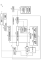
- FIG. FIG. 4 is a diagram showing a configuration example of a work setting unit and a robot motion calculation unit according to Embodiment 1;
- FIG. 11 is a diagram showing an example of multi-step batch motion calculation according to the first embodiment; A diagram showing an example of a trajectory generated by a process unit motion calculation and a trajectory generated by a multi-process batch motion calculation.
- 1 is a diagram showing a configuration example of a computer system that realizes the teaching support device according to Embodiment 1;
- FIG. FIG. 11 is a diagram showing a configuration example of a teaching support device according to a second embodiment;
- FIG. 10 is a diagram showing a configuration example of a work system according to a third embodiment;
- FIG. 11 is a diagram showing a configuration example of a work system according to a fourth embodiment;
- FIG. FIG. 11 is a diagram showing a configuration example of a work system according to a fifth embodiment;
- FIG. 1 is a diagram illustrating a configuration example of a work system according to a first embodiment
- a work system 6 of this embodiment includes a teaching support device 1 , an image sensor 2 , a robot control device 3 , a robot 4 and a sensor 5 .
- the work system 6 is a system that uses the robot 4 to perform work.
- the robot 4 is an example of a work machine, and may be, for example, an industrial robot that performs boxing, assembly, processing, transportation, packaging, etc., or a service robot that assists people. Further, the robot 4 may be an outdoor robot for agricultural work, construction work, or the like, or may be an indoor robot.
- the robot 4 is, for example, a multi-axis vertical articulated robot, but is not limited to this, and may be a linear motion robot or a robot combining linear motion and rotation. There are no restrictions on the type. In the following, an example in which the robot 4 is an industrial multi-axis vertical articulated robot will be described as an example.
- the robot control device 3 receives a robot motion command, which is a command relating to the motion of the robot, from the teaching support device 1, and sets a control amount for controlling the motors of the robot so that the robot 4 follows the received robot motion command.
- the operation of the robot 4 is controlled by calculating and outputting the control amount to the robot 4 .
- the robot control device 3 may correct the motion of the robot 4 using the detection result of the sensor 5 .
- the sensor 5 is a sensor that detects the position, posture, etc., of the work target of the robot 4, and is, for example, a two-dimensional or three-dimensional vision sensor.
- the robot control device 3 controls the motion of the robot 4 by driving motors (not shown) for each axis of the robot 4 .
- a general method can be used for the control in the robot control device 3, so a detailed description thereof will be omitted.
- the robot control device 3 is provided separately from the robot 4 in FIG. 1, the robot control device 3 may be included in the robot.
- the sensor 5 may be provided at a position different from that of the robot 4 or may be provided on the robot 4 .
- the image sensor 2 is a sensor that acquires a three-dimensional image, and acquires environmental measurement data by measuring the environment around the robot 4.
- Environmental measurement data is data obtained by imaging the environment with the image sensor 2 .
- the environment around the robot 4 is, for example, objects and structures in the area including the movable range of the robot 4 .
- the image sensor 2 is, for example, an RGB-D (Depth) sensor capable of obtaining a three-dimensional image by acquiring depth and color.
- the teaching support device 1 automatically generates an operation program corresponding to the work to be performed by the robot 4 based on the environmental measurement data from the image sensor 2 and the work content input by the user, and uses the operation program to perform the robot operation. A command is generated, and the generated robot operation command is transmitted to the robot control device 3 .
- the teaching support device 1 accepts the input of the work content itself by selecting it from a natural language or a video showing the work, so that even a user who is unfamiliar with programming can easily instruct the work content. It can be performed.
- the teaching support device 1 is, for example, a mobile terminal device such as a tablet, a smartphone, or a personal computer, but is not limited to a mobile terminal device.
- the teaching support device 1 includes a modeling section 11 , a robot motion calculation section 12 , a work information storage section 13 , a display section 14 , an input section 15 and a work setting section 16 .
- the modeling unit 11 acquires the environmental measurement data by receiving the environmental measurement data from the image sensor 2, and generates an environment model, which is a three-dimensional model of the environment, using the acquired environmental measurement data.
- the environment model is output to the display section 14 and the robot motion calculation section 12 .
- the modeling unit 11 generates an environment model by three-dimensional reconstruction that connects a plurality of partial three-dimensional data based on environmental measurement data, which is point cloud data, for example.
- the input unit 15 accepts input from the user.
- the input unit 15 receives input of work content from the user, and outputs the received work content (information indicating the work content) to the display unit 14 and the work setting unit 16 .
- the input unit 15 may receive the user's utterance as voice, or may receive the selection result selected by the user from options displayed on the display unit 14 .
- the input unit 15 includes a microphone (not shown) and a voice recognition unit that performs voice recognition processing.
- a microphone may be provided separately from the teaching support device 1 , and the voice acquired by the microphone may be input to the input unit 15 .
- the option When receiving a selection result selected by the user from the options displayed on the display unit 14, the option may be character information indicating a candidate for work content, or may be a moving image or an image.
- the input unit 15 receives a selection result by tapping, keyboard operation, mouse operation, or the like. Further, the input unit 15 may receive an input of work content or a selection result by image recognition of gestures or eye contact. When input is received by gesture or eye contact, the input unit 15 may have an imaging function, and an image captured by an imaging means different from the input unit 15 is input to the input unit 15. good too.
- the display unit 14 displays various information, images, videos, and the like. For example, the display unit 14 displays the work content received from the input unit 15 . Further, the display unit 14 displays the motion of the robot based on the environment model received from the modeling unit 11 and the robot model and the robot motion command (or information indicating the motion of the robot) received from the robot motion calculation unit 12 . Display by (Augmented Reality) display.
- the robot model may be stored in a model storage unit (not shown) of the teaching support device 1, and the display unit 14 may read the robot model from the model storage unit.
- the environment model may be stored in the model storage unit by the modeling unit 11 and read out from the model storage unit by the display unit 14 .
- the model storage unit may be provided outside the teaching support device 1 .
- the robot model to be used is designated by the robot motion calculation unit 12 or the work setting unit 16, and the display unit 14 is designated.
- the robot model that has been stored may be read from the model storage unit.
- the display unit 14 may be realized using hardware having a function of receiving input such as a touch panel.
- the display unit 14 may include a touch panel and a display data generation unit for performing AR display and the like, and the touch panel may have a part of the functions of the input unit 15 .
- an input from the user may be accepted by detecting that the user has tapped an image, character, or the like displayed on the touch panel.
- the work setting unit 16 converts the work content received from the input unit 15 into a programming language, and outputs work setting information including the conversion result to the robot motion calculation unit 12 .
- the work information storage unit 13 stores, for each work, a template indicating the motion of the robot 4 corresponding to the work in a work database (hereinafter referred to as work DB (Database)).
- the template defines the main part of the operation program corresponding to the work, and includes information indicating the operation corresponding to the operation program in natural language or animation.
- the work setting unit 16 causes the display unit 14 to display information indicating the templates.
- the information indicating the plurality of templates may be information indicating the operation of the work using characters, or may be identification information corresponding to the templates. Also, a moving image corresponding to the template may be displayed on the display unit 14 . Furthermore, the work setting unit 16 may cause the display unit 14 to display an explanatory moving image, an explanatory diagram, an explanatory text, etc. for each template.
- the display unit 14 displays, for example, information indicating the template as a pull-down menu, and the input unit 15 receives the input of the selection result.
- the input section 15 outputs the selection result to the work setting section 16 . It should be noted that the display method of the information indicating the template is not limited to this example.
- the work setting unit 16 acquires the work content corresponding to the template using the selection result of the template via the input unit 15, recognizes the work content based on the acquired input, and converts the recognized content into a programming language. do.
- the template shows an overview of typical work, and is created for each work such as boxing work, assembly work, and packaging work.
- boxing work the robot 4 grabs an object and packs it in a target location.
- the information indicates the action of "grabbing X, carrying it to Y, and packing it in Y.”
- X is the object and Y is the place to fill.
- the content of work is determined by inputting X and Y from the user.
- the model may also include the number of items to pack, such as "grab X, carry to Y, and pack Z items into Y.”
- the work information storage unit 13 stores work information related to work performed by the robot 4 as a work DB.
- the work information includes, for example, a model corresponding to each work described above and constraints for each model.
- the robot motion calculation unit 12 calculates the motion of the robot 4 while avoiding interference between the robot 4 and the environment, based on the work content input by the user and the environment model, which is a three-dimensional model that models the environment of the working machine. It is a motion calculation unit that generates a trajectory. Specifically, the robot motion calculation unit 12 uses the work setting information received from the work setting unit 16, the environment model received from the modeling unit 11, and the detection result of the sensor 5 to perform work according to the work content. is determined so that the robot 4 does not interfere with the environment. In FIG. 1 , the robot motion calculation unit 12 acquires the detection result of the sensor 5 via the robot control device 3 , but the detection result of the sensor 5 may be acquired from the sensor 5 .
- the trajectory of the robot 4 is determined by collectively treating work including a plurality of steps as one motion.
- the robot motion calculation unit 12 generates a robot motion command, which is a motion command for the robot 4 , based on the determined trajectory, and transmits the generated robot motion command to the robot control device 3 .
- FIG. 2 is a flow chart showing an example of a processing procedure in the teaching support device 1 of this embodiment.
- the teaching support device 1 determines whether or not there is an environment model (step S1). Specifically, the modeling unit 11 determines whether an environment model has already been generated.
- step S2 the teaching support device 1 generates an environment model (step S2) and advances the process to step S3.
- step S2 the modeling unit 11 generates an environment model by three-dimensional reconstruction using environmental measurement data acquired by the image sensor 2, for example.
- FIG. 3 is a diagram schematically showing an example of the environmental measurement data acquisition method according to the present embodiment.
- FIG. 3 shows an example in which the robot 4 is caused to perform the task of “packing fried chicken into a bento box.”
- the image sensor 2 is attached to the teaching support device 1, and the user operates the image sensor 2 via the teaching support device 1 or directly operates the image sensor 2 to
- the surroundings of the robot 4 are photographed from a plurality of locations. Thereby, a plurality of three-dimensional images photographed from a plurality of locations are acquired.
- the modeling unit 11 generates an environment model, which is a three-dimensional model of the environment, by performing three-dimensional reconstruction by joining these three-dimensional images.
- the environment model is represented by, for example, MESH, OBB (Oriented Bounding Box), polygons, etc.
- the representation format of the environment model is not limited to these, and any format may be used.
- 3D reconstruction is a technology that extracts feature points and planes from multiple partially captured environmental measurement data and connects them to generate an overall 3D model.
- an example of generating a three-dimensional model using environmental measurement data acquired by the image sensor 2, which is an RGB-D sensor, will be described.
- a three-dimensional model may be generated using a plurality of them.
- the robot 4 packs the fried chicken 32 stacked in the weight 31 into the target compartment 34, which is a compartment for packing the fried chicken 32, among the multiple compartments of the lunch box 33. conduct.
- the robot 4 performs this operation, in addition to the fried chicken 32 which is the object to be moved by the robot 4, a bento box 33, a weight 31, and a table (not shown) on which the weight 31 is placed are present in the surroundings. It is necessary to understand the environment, such as the object that moves, the surrounding structure, and so on.
- the teaching support device 1 of the present embodiment automatically generates an environment model by the user capturing an image of the surroundings with the image sensor 2 .
- the senor 5 is provided separately from the robot 4 for detecting the position and orientation of the fried chicken 32, which is the object. It may be attached to the robot 4 or may be attached to the robot 4 .
- the image sensor 2 is attached to the teaching support device 1, but the image sensor 2 is provided separately from the teaching support device 1, and the user carries the image sensor 2 around. You can take pictures.
- the teaching support device 1 may acquire the environmental measurement data by connecting it to the image sensor 2 by wire or wirelessly. Environmental measurement data may be read.
- environment measurement data is not limited to the example shown in FIG. good.
- environmental measurement data can be obtained by attaching the sensor 5 to the tip of the robot 4 or the like, operating the robot 4, and performing imaging with the image sensor 2. may be
- step S3 the teaching support device 1 accepts the selection of work.
- the work setting unit 16 causes the display unit 14 to display a template for each work (a template for each work type) stored in the work DB of the work information storage unit 13, and the input unit 15 displays the user's selection result. , and outputs the received selection result to the work setting unit 16 .
- the process of step S3 may not be performed.
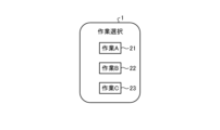
- FIG. 4 is a diagram showing an example of the work selection screen according to this embodiment.
- buttons 21, 22, and 23 corresponding to each task are displayed, and the user selects the task by pressing the corresponding button.
- FIG. 4 is an example, and the contents of the work selection screen and the selection method are not limited to this example.
- the teaching support device 1 accepts an instruction for the content of the selected work (step S4).
- the work setting unit 16 outputs to the input unit 15 a template corresponding to the selection result selected in step S3.
- the input unit 15 receives an input from the user, determines the content of the selected work (work content) based on the input information and the template, and displays the determined work content on the display unit 14 and the work settings. Output to the unit 16 .
- FIG. 5 is a diagram showing an example of information received as work content by the input unit 15 of the present embodiment.
- work A is selected, and as a template for work A, an action of "grabbing X, carrying it to Y, and filling Y with Z pieces" is defined.
- the input unit 15 recognizes the detected voice by voice recognition using a template.
- the speech recognition may be general-purpose speech recognition, or may be used to recognize the work content of the robot 4, such as performing speech recognition using a trained model by machine learning specialized for the work content using the robot 4. It may be specialized processing.
- the input unit 15 causes the display unit 14 to display information prompting the input of the content when there is information that has not been input among X, Y, and Z or information that could not be recognized as a result of voice recognition. By doing so, the input of missing information is accepted. For example, if it is possible to recognize that X is "fried chicken” and Y is "lunch box” by detecting and recognizing the utterance "put fried chicken in a lunch box", the information of Z is Since it is insufficient, the display unit 14 is caused to display a question about the number of fried chicken. Instead of the display unit 14, a speaker may be used to present the question to the user by voice. Alternatively, audio may be presented to the user along with the display. In addition, when the lunch box is divided into a plurality of compartments, a question is presented to the user as to which compartment of the "lunch box" the fried chicken is to be packed in, prompting the user to enter the compartment.
- the input unit 15 is not limited to the example using the voice recognition described above, and displays information indicating options of X, Y, and Z on the display unit 14 as characters, images, etc., and by tapping and other selection operations, Inputs of X, Y, and Z may be accepted.
- the teaching support device 1 displays the work content (step S5). Specifically, the input unit 15 instructs the display unit 14 to display the work content received in step S4, and the display unit 14 displays the work content.
- the display unit 14 may display an AR motion of the robot corresponding to the work content. This allows the user to confirm whether the determined work content is desired. If the work content is not what is desired, the process from step S3 or the process of step S4 may be executed again.
- the teaching support device 1 calculates the robot motion from the work content and the environment model (step S6).
- the work setting unit 16 outputs work setting information including the result of converting the work contents into the operation program to the robot operation calculation unit 12 .
- the robot motion calculation unit 12 determines the trajectory of the robot using the work setting information received from the work setting unit 16 and the environment model received from the modeling unit 11 or read from a model storage unit (not shown). Generate robot motion commands based on the trajectory.
- the robot motion calculation unit 12 treats, for example, a plurality of motions corresponding to a plurality of processes constituting a work as one batch motion, and the start position and end position of the batch motion and constraints on the motion of the working machine. and conditions to generate motion trajectories. Note that the method of determining the trajectory of the robot motion calculation unit 12 is not limited to this example.
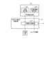
- FIG. 6 is a diagram showing a configuration example of the work setting unit 16 and the robot motion calculation unit 12 of this embodiment.
- the work setting section 16 includes a work designating section 161 and a target information setting section 162 .
- the work designation unit 161 generates an operation program corresponding to the work content received by the input unit 15 as work designation information for designating the work.
- the target information setting unit 162 generates target object information including information indicating, for example, the target object and the supply state, based on the work content.
- the target indicates the type of target, for example, fried chicken or screw.
- the supply state indicates how the objects are supplied, such as whether the objects are stacked and supplied or whether they are conveyed by a belt conveyor or the like.
- the supply state is, for example, predetermined for each object, and correspondence information indicating the correspondence between the object and the supply state is stored in the work DB.
- the object information setting unit 162 determines the supply state corresponding to the object by referring to the correspondence information in the work DB.
- correspondence information indicating the correspondence between the information and the object is similarly stored in the work DB.
- the information setting unit 162 may obtain the information using this correspondence information and include it in the target information.
- the robot motion calculation unit 12 outputs the work designation information generated by the work designation unit 161 and the target object information generated by the target information setting unit 162 to the robot motion calculation unit 12 as work setting information.
- the operation setting unit 16 generates an operation program for operating the robot 4
- the robot operation calculation unit 12 may generate the operation program.
- the robot motion calculation unit 12 includes a batch motion calculation unit 121 .
- the batch operation calculation unit 121 performs multi-step batch operation calculation using work designation information, target object information, and an environment model and sensor information (not shown in FIG. 6) to calculate separately for each step.
- a trajectory of the robot 4 whose operation time is shorter than that of the trajectory that is joined together is generated.
- FIG. 7 is a diagram showing an example of multi-step batch operation calculation according to the present embodiment.
- FIG. 7 shows an example in which the robot 4 performs the task of packing the fried chicken 32 stacked on the weight 31 into the target section 34 of the lunch box 33 .
- this work consists of process #1 in which the robot 4 takes out the fried chicken 32 from the weight 31, and the robot 4 takes out the fried chicken 32 from the weight 31 to the lunch box 33. It includes a step #2 which is a step of carrying, and a step #3 which is a step of packing the fried chicken 32 into the target section 34 of the lunch box 33 by the robot 4. ⁇
- a trajectory that does not interfere with the environment by a step-by-step motion calculation, which is a calculation for optimizing the motion of the robot 4 for each step.
- the collective motion calculation unit 121 shown in FIG. A trajectory that shortens the operation time is generated after considering constraints (orientation of the trajectory and movement speed).
- the robot motion calculation unit 12 may generate a trajectory that does not interfere with the environment by the process unit motion calculation.
- FIG. 8 is a diagram showing an example of a trajectory generated by a process unit motion calculation and a trajectory generated by a multi-process batch motion calculation.
- the upper part of FIG. 8 shows an example of a trajectory generated by the process unit motion calculation.
- the motions #1 to #4 corresponding to the process #1 shown in FIG.
- Trajectories of motions #5 and #6 corresponding to #2 and motion #7 corresponding to process #3 shown in FIG. 7 are generated.
- Motions #1 to #3 are motions in which the robot 4 starts to move toward the weight 31, but the motions of the robot 4 are slowed down due to motion restrictions near the start and stop of the motions.
- Operation #2 is a high-speed operation.
- Operation #4 is an operation of closing a hand, which is a gripping portion provided at the tip of the robot 4 . It is assumed that the hand is open at the start of work. Action #5 is a low-speed action to start moving to the lunch box 33, and action #6 is a high-speed action to move to the lunch box 33. By opening the hand in operation #7, the fried chicken 32 is packed in the target section 34 of the lunch box 33. - ⁇ Note that the operation in FIG. 8 is an example, and the specific operation is not limited to the example shown in FIG.
- the target position of the robot 4 is determined based on sensor information.
- an optimum trajectory is generated for each process based on the target position and the environment model.
- the optimum trajectory is, for example, a trajectory that minimizes the evaluation function under the constraint conditions and that does not interfere with the environment.
- the optimum trajectory is not limited to the trajectory that minimizes the evaluation function, and may be the trajectory that makes the evaluation function equal to or less than the threshold.
- the evaluation function is, for example, at least one of the working time of the robot 4, the power consumption of the robot 4, the moving distance of the robot 4, and the like. Constraints are constraints on the speed and movement direction of the robot, and are stored in the work DB.
- the collective motion calculation unit 121 calculates an optimal trajectory for motion A.
- FIG. That is, the batch motion calculation unit 121 integrates motions #1 to #3 as motion A, and uses sensor information, object information, and speed constraint conditions to determine one trajectory whose evaluation function is equal to or less than the threshold. Generate.
- the collective motion calculation unit 121 generates a trajectory using speed constraints with reference to the remaining distance.
- the batch motion calculator 121 similarly integrates motions #5 and #6 as motion B to generate one trajectory.
- the teaching support device 1 displays the robot motion (step S7).
- the robot motion calculation unit 12 outputs information indicating the robot motion corresponding to the generated trajectory (motion trajectory) to the display unit 14, and the display unit 14 displays the motion of the robot 4 corresponding to the motion trajectory.
- the display unit 14 can display the robot motion in AR by displaying the robot model in a desired posture based on input of joint angle information, which is motion commands at each moment. This allows the user to confirm whether the determined robot motion is the desired one. If the robot motion is not desired, the process from step S3 or step S4 may be performed again.
- the teaching support device 1 transmits a robot operation command to the robot control device 3 (step S8), and ends the process. Specifically, in step S ⁇ b>8 , the robot motion calculation unit 12 transmits the robot motion command generated in step S ⁇ b>7 to the robot control device 3 .
- the robot motion calculation unit 12 temporarily stops the sensor 5 above the gripped object, The position of the target object and the like may be recognized by capturing the image and acquiring the sensor information.
- the sensor 5 is attached to the robot 4, the sensor 5 also moves along with the motion of the robot 4, and blurring occurs during photographing.
- the sensor 5, which is a three-dimensional sensor is fixed above the object, the robot 4 is not stopped above the object to be grasped, and after the object has been grasped and the object has been passed through the area to be grasped, the sensor 5 may be imaged and the sensor information may be acquired to recognize the position of the target object.
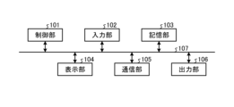
- FIG. 9 is a diagram showing a configuration example of a computer system that implements the teaching support device 1 of this embodiment.
- this computer system comprises a control section 101, an input section 102, a storage section 103, a display section 104, a communication section 105 and an output section 106, which are connected via a system bus 107.
- control unit 101 is, for example, a processor such as a CPU (Central Processing Unit), and executes a program in which processing in the teaching support device 1 of the present embodiment is described.
- a part of the control unit 101 may be implemented by dedicated hardware such as a GPU (Graphics Processing Unit) or an FPGA (Field-Programmable Gate Array).
- the input unit 102 is composed of, for example, a keyboard and a mouse, and is used by the user of the computer system to input various information.
- Input unit 102 may include a microphone.
- the storage unit 103 includes various memories such as RAM (Random Access Memory) and ROM (Read Only Memory) and storage devices such as hard disks, and stores programs to be executed by the control unit 101 and necessary information obtained in the process of processing.
- the storage unit 103 is also used as a temporary storage area for programs.
- the display unit 104 includes a display, LCD (liquid crystal display panel), etc., and displays various screens to the user of the computer system. Also, the display unit 104 may be a touch panel having a function as the input unit 102 .
- a communication unit 105 is a receiver and a transmitter that perform communication processing.
- the output unit 106 is a printer, speaker, or the like. Note that FIG. 9 is an example, and the configuration of the computer system is not limited to the example in FIG.
- a computer program is stored in a storage unit from a CD-ROM or DVD-ROM set in a CD (Compact Disc)-ROM drive or a DVD (Digital Versatile Disc)-ROM drive (not shown).
- 103 installed.
- the program read from storage unit 103 is stored in the main storage area of storage unit 103 .
- the control unit 101 executes processing as the teaching support device 1 of this embodiment according to the program stored in the storage unit 103 .
- a recording medium such as a CD-ROM or a DVD-ROM is used to provide a program describing the processing in the teaching support device 1.
- a program provided via a transmission medium such as the Internet via the communication unit 105 may be used depending on the capacity of the program to be provided.
- the teaching support program of the present embodiment includes, for example, a step of acquiring a work content input by a user and an environment model, which is a three-dimensional model of the environment of a work machine, and a step of acquiring the work content and the environment model. and generating a motion trajectory of the work machine that avoids interference between the work machine and the environment.
- the modeling unit 11, the robot motion calculation unit 12, and the work setting unit 16 shown in FIG. 1 are executed by the control unit 101 shown in FIG. Realized.
- the storage unit 103 shown in FIG. 9 is also used to realize the modeling unit 11, the robot motion calculation unit 12, and the work setting unit 16 shown in FIG.
- the work information storage unit 13 shown in FIG. 1 is a part of the storage unit 103 shown in FIG.
- Display unit 14 shown in FIG. 1 is realized by display unit 104 and control unit 101 shown in FIG.
- Input unit 15 shown in FIG. 1 is realized by input unit 102 and control unit 101 shown in FIG. Further, when the input unit 15 receives input by voice, the input unit 102 may include a microphone, or an external microphone may be used.
- the teaching support device 1 may be realized by a plurality of computer systems.
- the input unit 15, the display unit 14, and the work setting unit 16 shown in FIG. may be implemented.
- components other than the robot motion calculation unit 12 may be implemented by a computer system such as a tablet, and the robot motion calculation unit 12 may be implemented by another computer system.
- the robot control device 3 may include some of the functional units of the teaching support device 1 shown in FIG.
- the teaching support device 1 may be realized by a cloud computer system.
- the teaching support device 1 generates an environment model based on environmental measurement data acquired by the image sensor 2, but the environment model is generated as a CAD (Computer Aided Design) model or the like. environment model may be input from the outside.
- the teaching support device 1 receives an environment model from another device (not shown), and the environment model is input to the robot motion calculation unit 12 and the display unit 14 .
- the work system 6 does not need to include the image sensor 2 and the teaching support device 1 does not need to include the modeling section 11 .
- the teaching support device 1 shown in FIG. 1 further has a function of inputting an externally input environment model to the robot operation calculation unit 12 and the display unit 14, and the environment model based on the environment measurement data, You may enable it to utilize both the created environment model.
- the teaching support device 1 of the present embodiment accepts input of work details from the user and automatically generates an operation program based on the accepted work details.
- a program for each work is registered as template information in the work DB, and a person corresponding to the work is loaded into the robot motion calculation unit 12 .
- the robot motion calculation unit 12 provides the loaded program with information on the size of the work area and the position of the work area related to the work task.
- the program is configured so that the necessary teaching point setting and trajectory generation of the program loaded from the template can be automatically performed. That is, no user input is required to specify the robot motion. Therefore, by designating only information such as the size of the work area, the position of the work area, and the work target, the robot can be moved.
- the teaching support device 1 of the present embodiment automatically generates an environment model using environmental measurement data acquired by the image sensor 2, and determines a trajectory of the robot that does not interfere with the environment using the generated environment model. Therefore, the time required to create the environment model can be shortened compared to the case where the user creates the environment model itself.
- the teaching support device 1 of the present embodiment since the teaching support device 1 of the present embodiment generates the trajectory of the robot 4 by treating a plurality of steps constituting a work as one operation, the operation time of the robot can be shortened. Adjustment time can be shortened.
- the teaching support device 1 creates a template corresponding to each task in advance, and presents information indicating the template corresponding to the task to the user, so that even an inexperienced user can perform the task. Content can be entered easily.
- the user can select a more appropriate template (work).
- FIG. 10 is a diagram illustrating a configuration example of a teaching support device according to a second embodiment;
- a teaching support device 1a of the present embodiment is the same as the teaching support device 1 of the first embodiment except that the modeling unit 11 is removed from the teaching support device 1 shown in FIG. 1 and the simulation unit 17 is added.
- Components having functions similar to those of the first embodiment are denoted by the same reference numerals as those of the first embodiment, and overlapping descriptions are omitted. Differences from the first embodiment will be mainly described below.
- the simulation unit 17, which is a simulator, performs a simulation that simulates the motion of the robot 4.
- the simulation result can be used for preliminary examination before actually installing the robot 4 .
- the setting of the work content when performing the simulation and the processing of the robot motion calculation unit 12 are the same as in the first embodiment.
- the environment model created as a CAD model is input to the robot motion calculation unit 12 .
- the robot motion calculation unit 12 outputs the robot motion command, the robot model, and the environment model to the simulation unit 17 .
- the simulation unit 17 performs a simulation simulating the motion of the robot 4 using the motion trajectory determined by the robot motion calculation unit 12 and the environment model. For example, it performs a simulation for simulating the motion of the robot 4 using the robot motion command, the robot model, and the environment model received from the robot motion calculation unit 12 and outputs the simulation result, which is the result of the simulation, to the display unit 14 .
- the display unit 14 displays the simulation results.
- the display unit 14 may display a visual programming screen, or may display the visual programming screen and the simulation results in a superimposed manner.
- the visual programming screen is, for example, a screen for specifying actions by arranging blocks.
- a simple programming language for block programming such as "Scratch” can be used. is not limited to this example.
- FIG. 11 is a diagram showing an example of the display screen of this embodiment.
- the simulation result is displayed on the teaching support device 1a.
- the visual programming screen is superimposed and displayed.
- FIG. 11 is an example, and the specific display screen is not limited to the example shown in FIG.
- the visual programming screen it is possible to accept inputs such as changes to sensors and robots, and changes to the placement of sensors and robots may be accepted, for example, on the screen where the simulation results are displayed. For example, by selecting and moving the part where the robot is displayed, the change of the placement of the robot may be accepted. These changes are accepted by the input unit 15 and the accepted results are output to the work setting unit 16 .
- a template list is displayed as a work item list, and when the user selects a work, the robot, hand, and sensor presets corresponding to the selected work are displayed.
- a robot list (various types of robots) and a sensor list (vision sensor, force sensor, tactile sensor, distance measurement sensor, etc.) are displayed, and you can tap and drag the element you want to add from these lists to the screen. It may be possible to make changes and additions in When a sensor is added, the physical quantity val (contact force with the environment, position of the object, distance between specified points) measured by the sensor is defined.
- the simulation unit 17 uses the defined physical quantity val as an input, the simulation unit 17 checks the feasibility of operation based on the operation conditions of the block programming, and displays the simulation result as a moving image on the display unit 14 . For example, when an object is moving on a conveyor, if the position of the vision sensor that detects the position of the object is too close to the robot, problems such as the recognition time being delayed may occur. An appropriate positional relationship can be considered in advance by simulating.
- the display unit 14 displays a screen for performing block programming
- the input unit 15 receives an input for changing the robot in the block programming
- the robot operation calculation unit 12 receives the input unit 15.
- the trajectory may be generated reflecting the input.
- an input for adding or changing a sensor used for determining the motion of the robot may be received, and the robot motion calculation unit 12 may generate a trajectory by reflecting the input received by the input unit 15 .
- FIG. 10 shows the functional configuration for performing simulation
- the teaching support apparatus 1a having the configuration shown in FIG. A simulation unit 17 may be added to the device 1 so that both the operation described in the first embodiment and the simulation can be performed.
- the hardware configuration of the teaching support device 1a of the present embodiment is the same as that of the teaching support device 1 of the first embodiment.
- the simulation unit 17 is realized by executing a computer program stored in the storage unit 103 shown in FIG. 9 by the control unit 101 shown in FIG.
- the storage unit 103 shown in FIG. 9 is also used for realizing the simulation unit 17 .
- the teaching support device 1a may be composed of a plurality of computer systems.
- the teaching support device 1a is provided with a modeling unit 11, the modeling unit 11 generates an environment model using environmental measurement data, and the simulation unit 17 is generated.
- a simulation may be performed using an environment model.
- the teaching support device 1a is configured to perform a simulation that simulates the motion of the robot, so the simulation results can be used for prior examination.
- FIG. 12 is a diagram illustrating a configuration example of a work system according to a third embodiment;
- the work system 6b of the present embodiment is the same as the work system 6 of the first embodiment except that the teaching support device 1b is provided instead of the teaching support device 1.
- FIG. Components having functions similar to those of the first embodiment are denoted by the same reference numerals as those of the first embodiment, and overlapping descriptions are omitted. Differences from the first embodiment will be mainly described below.
- the teaching support device 1b is the same as the teaching support device 1 of Embodiment 1 except that it includes a modeling unit 11a, an input unit 15a and a work setting unit 16a instead of the modeling unit 11, the input unit 15 and the work setting unit 16. be.
- the work setting unit 16a is the same as the work setting unit 16 of Embodiment 1, except that a motion correction unit 163 is added.
- the teaching support device 1b of the present embodiment receives corrections of at least one of the environment model and the actions of the robot 4 in addition to the same actions as in the first embodiment, and reflects the corrections.
- FIG. 13 is a flow chart showing an example of a processing procedure in the teaching support device 1b of this embodiment. Steps S1 to S7 are the same as in the first embodiment.
- step S9 the teaching support device 1b determines whether or not there is a correction instruction. Specifically, the input unit 15a determines whether or not an instruction to modify at least one of the environment model and the motion of the robot 4 has been received from the user. If there is a correction instruction (step S9 Yes), the teaching support device 1b corrects the robot motion (step S10) and advances the process to step S8. If there is no correction instruction (step S9 No), the teaching support device 1b advances the process to step S8. Step S8 is the same as in the first embodiment.
- the trajectory of the robot 4 displayed in step S7 is a trajectory that is considered to be a threat to the worker collaborating with the robot 4, at least a part of the prohibited area and the permitted area is set to the input unit 15a.
- the display unit 14 is a touch panel that also has a part of the functions of the input unit 15a, the user can tap the position of at least one of the prohibited area model and the permitted area while the environment is being displayed.
- the specification specifies at least one of a prohibited area model and a permitted area model.
- the input unit 15a outputs at least one of the input prohibited area model and allowed area model to the modeling unit 11a.
- the modeling unit 11a modifies the environment model by adding at least one of the prohibited area model and the permitted area model, and displays the modified environment model on the display unit 14 and the robot motion calculation. Output to the unit 12 .
- the robot motion calculation unit 12 uses the modified environment model to perform the robot motion calculation in the same manner as in the first embodiment. That is, the robot motion calculation unit 12 generates a trajectory that reflects the correction instruction received by the input unit 15a. Specifically, when the prohibited area model is added, the robot motion calculation unit 12 determines the trajectory so that the robot 4 does not pass through the prohibited area in addition to the condition of not interfering with the environment. Further, when the permitted area model is added, the robot motion calculation unit 12 determines the trajectory under the condition that the robot 4 can pass within the permitted area even if it interferes with the environment.
- the user sets the prohibited area to an area where workers collaborating with the robot 4 feel threatened.
- the permitted area near the object may be automatically set using sensor information acquired by the sensor 5 .
- the modeling unit 11a may use the sensor information to automatically add the area around the object indicated by the sensor information as the allowed area model.
- the display unit 14 displays a button or the like for increasing the size of a partial model selected by the user from among the environment models from the original size, and the input unit 15a responds when the button is pressed.
- the modeling unit 11a may be instructed to enlarge the selected partial model.
- the modeling unit 11a increases the size of the partial model selected by the user according to a predetermined rule based on the instruction from the input unit 15a.
- a predetermined rule may be a rule that increases the size by a fixed amount in a particular direction or in all directions, or a rule that increases the size in a particular direction or in all directions by multiplying the size by a real number factor of 1 or more. It may be made larger, or the size may be increased by other methods. This creates a trajectory with a margin of distance from the actual environment.
- the input unit 15a accepts the user's utterance as voice and recognizes the correction target and the correction content, such as "Take P a little to the right," as the correction content of the motion of the robot 4. may be recognized.
- the input unit 15a outputs the voice recognition result to the work setting unit 16a, and the work setting unit 16a corrects the operation program according to the content of correction.
- items to be corrected such as the target position of the motion of the robot 4
- options may be presented to the user
- input of selection results may be accepted, and correction details of the item may be accepted by voice.
- the input unit 15 a may receive an input of a change in the constraint conditions of the motion of the robot 4 as the modification of the motion of the robot 4 .
- the correction contents of the motion of the robot 4 are output to the robot motion calculation unit 12 via the work setting unit 16a, and the robot motion calculation unit 12 reflects the correction to generate a trajectory.
- the display unit 14 displays buttons for instructing changes in the AR display speed, temporary stop of the AR display operation, and the like. Instructions for display may be received.
- the input unit 15a notifies the display unit 14 of the received instruction, and the display unit 14 controls the AR display according to the notification.
- the user can slow down the speed and check it in detail, or stop it and check it in detail.
- a correction function is added to the configuration example shown in FIG. 1, but the correction function may be added when using a generated environment model. Also, the function of executing the simulation described in the second embodiment may be added to the teaching support device 1b of the present embodiment.
- the hardware configuration of the teaching support device 1b of the present embodiment is the same as that of the teaching support device 1 of the first embodiment. Also, as in the first embodiment, the teaching support device 1b may be composed of a plurality of computer systems.
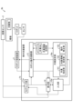
- FIG. 14 is a diagram illustrating a configuration example of a work system according to a fourth embodiment.
- the work system 6c of the present embodiment is the same as the work system 6b of the third embodiment except that the teaching support device 1c is provided instead of the teaching support device 1b and the analysis device 7 is added.
- Components having functions similar to those of the third embodiment are denoted by the same reference numerals as those of the third embodiment, and overlapping descriptions are omitted. Differences from the third embodiment will be mainly described below.
- a teaching support device 1c of the present embodiment has a transmitting/receiving unit 18 added to the teaching support device 1b of the third embodiment.
- the work setting unit 16a stores the work setting information in the work DB of the work information storage unit 13, so that the work DB stores settings such as work (type of work), target object, target area, etc., related to the set work. Information is stored.
- the robot motion calculation unit 12 outputs motion information, which is information related to robot motion such as a robot motion command, to the transmission/reception unit 18 .
- the transmitting/receiving unit 18 reads the setting information from the work DB, and transmits the read setting information and the motion information received from the robot motion calculation unit 12 to the analysis device 7 .
- the analysis device 7 includes a transmission/reception section 71 and an analysis section 72 .
- the transmitting/receiving unit 71 receives setting information and operation information from the teaching support device 1c, receives measurement information from the peripheral device 8, and receives success/failure information indicating the success or failure of work from the teaching support device 1c or another device.
- the obtained information is output to the analysis unit 72 .
- the success/failure information may be received by the input unit 15a of the teaching support device 1c from the user and transmitted to the analysis device 7 by the transmission/reception unit 18, or may be received by another device (not shown) from the user. may be transmitted to the analysis device 7 by Further, the transmission/reception unit 71 transmits the analysis result received from the analysis unit 72 to the teaching support device 1c.
- the analysis unit 72 uses the setting information, the operation information, the measurement information, and the success/failure information to analyze the factors that are likely to cause failure, and outputs the analysis results to the transmission/reception unit 71 .
- the peripheral device 8 is, for example, a sensor that detects the state of the robot 4, and is various sensors such as a temperature sensor, a motor speed sensor, and a vibration sensor attached to at least one of the robot 4 and the environment.
- the analysis device 7 receives the measurement information directly from the peripheral device 8, but the analysis device 7 receives the measurement information via the robot control device 3 or the teaching support device 1c. Alternatively, the measurement information may be received via another device (not shown).
- the analysis unit 72 classifies, for example, input information composed of setting information, operation information, measurement information, and success/failure information into groups with the same work content or groups with similar work content.
- the analysis unit 72 determines whether each item of the operation information and the measurement information exceeds the normal range for each group, and stores the correspondence between the normal range determination result and the success/failure information.
- the analysis unit 72 expresses average behavior as a regression model from data acquired when performing a certain task, and obtains in advance a region (normal range) distributed during normal operation. It may be judged as an abnormality by evaluating how much it deviates from it.
- the normal range is statistically defined as normal if it is within 3 ⁇ , and abnormal if it is more than 3 ⁇ , based on the feature value (for example, how much the sensor output deviates from the normal value) and its variance when it is tried multiple times. can do.
- the analysis unit 72 determines that the determination result corresponding to the input information indicating that the success/failure information indicates failure deviates from the normal range, and the determination result corresponding to the input information indicating that the success/failure information indicates success. is within the normal range, and the extracted items are determined as information corresponding to the influencing factor.
- the measurement information of sensor K corresponds to the influencing factor.
- the measurement information of sensor K corresponds to the influencing factor. be informational. For example, if sensor K is the temperature of part P of robot 4, part P is likely to be the influencing factor of the failure.
- the analysis unit 72 may determine the item as information corresponding to the influence factor. In addition, using the accumulated input information, the analysis unit 72 determines the normal range of each item by machine learning such as cluster analysis using the input information when the success/failure information indicates success or a statistical method. may Further, the analysis device 7 may perform analysis using information acquired from a plurality of teaching support devices 1c.
- the analysis unit 72 acquires information indicating the type of failure (details of failure) in the event of failure as success/failure information, and in the event of failure, the operator or the like checks the robot 4 to determine the location of the cause.
- machine learning may be performed using the identified locations as correct data.
- the analysis unit 72 generates a learned model through supervised learning using multiple data sets each including a type of failure and factors (parts serving as factors) that are the corresponding correct data.
- the analysis unit 72 may infer factors by inputting the type of failure into the learned model.
- At least one of the above-described input information may be used as input data to generate a trained model, or at least one of the above-described input information may be used as input data to generate a trained model.
- Other examples include the following.
- an operator intentionally causes a specific abnormal state, and the data of the output of each device and the error signal at that time are collected multiple times.
- time-series data of each signal or information graphed from time-series data is input and machine learning is performed.
- the abnormal state may be determined while collecting information or after collecting information.
- the system in particular, in the case of collecting information online, it is possible to obtain the effect that the system can be stopped in advance before the system fails if a somewhat similar abnormal state occurs.
- Further examples include the following.
- data obtained from multiple mechanical systems are collected in a server, and supervised based on a database containing at least one of the output of each sensor, error signal, and condition monitoring signal labeled with abnormal states.
- the analysis method of the analysis unit 72 described above is an example, and the analysis method of the analysis unit 72 is not limited to the example described above. Also, the information used for analysis by the analysis unit 72 is not limited to the above example.
- the transmission/reception unit 18 of the teaching support device 1c Upon receiving the analysis result from the analysis device 7, the transmission/reception unit 18 of the teaching support device 1c outputs the analysis result to the display unit 14, and the display unit 14 displays the analysis result.
- the teaching support device 1c transmits, for example, at least one of the information indicating the work content and the motion information to the analysis device 7, and the analysis device 7 detects the state of the robot 4.
- the analysis device 7 uses the information obtained from the sensor, the information indicating the content of the work, and the success/failure information indicating the success or failure of the work, the causes of the failure of the work are analyzed.
- the analysis result is transmitted to the teaching support device 1c.
- the display unit 14 of the teaching support device 1 c displays the analysis results received from the analysis device 7 .
- the user can grasp the analysis results displayed on the display unit 14, that is, the presumed factors, and try to take some action on the corresponding points. As a result, it is possible to facilitate recovery from the failure.
- the hardware configuration of the teaching support device 1c of the present embodiment is the same as that of the teaching support device 1 of the first embodiment. Moreover, as in the first embodiment, the teaching support device 1c may be composed of a plurality of computer systems.
- the analysis device 7 of the present embodiment is also implemented by a computer system as illustrated in FIG. 9 of the first embodiment.
- the analysis device 7 may be constructed on a cloud system.
- the teaching support device 1 described in Embodiment 1 may transmit information to the analysis device 7, acquire analysis results from the analysis device 7, and display them.
- FIG. 15 is a diagram of a configuration example of a work system according to a fifth embodiment;
- the working system 6d of the present embodiment is the same as the working system 6 of the first embodiment except that the teaching support device 1d is replaced with the teaching support device 1d.
- Components having functions similar to those of the first embodiment are denoted by the same reference numerals as those of the first embodiment, and overlapping descriptions are omitted. Differences from the first embodiment will be mainly described below.
- a teaching support device 1d of the present embodiment is the same as the teaching support device 1 of Embodiment 1 except that it includes a setting information acquisition unit 19 instead of the work setting unit 16 and the input unit 15.
- the setting information acquisition unit 19 of the teaching support device 1d receives the same work setting information as the work setting information output by the work setting unit 16 of the first embodiment to the robot motion calculation unit 12 from another device (not shown), It outputs the received work setting information to the robot motion calculation unit 12 .
- the teaching support device 1d receives the work setting information from the other teaching support device. to receive The teaching support device 1d of the present embodiment can thereby reduce the user's load.
- the hardware configuration of the teaching support device 1d of the present embodiment is the same as that of the teaching support device 1 of the first embodiment. Also, as in the first embodiment, the teaching support device 1d may be configured with a plurality of computer systems.
Landscapes
- Engineering & Computer Science (AREA)
- Human Computer Interaction (AREA)
- Manufacturing & Machinery (AREA)
- Physics & Mathematics (AREA)
- General Physics & Mathematics (AREA)
- Automation & Control Theory (AREA)
- Robotics (AREA)
- Mechanical Engineering (AREA)
- Manipulator (AREA)
- Numerical Control (AREA)
Abstract
本開示にかかる教示支援装置(1)は、ユーザから入力された作業内容とロボット(4)の環境をモデル化した3次元モデルである環境モデルとに基づいて、ロボット(4)と環境との干渉を回避した、ロボット(4)の動作軌道を生成するロボット動作演算部(12)、を備える。
Description
本開示は、作業機械の教示を支援する教示支援装置、作業システム、教示支援方法および教示支援プログラムに関する。
産業ロボットをはじめとした作業機械を用いた作業では、作業機械に所望の動作を行わせるための位置情報を教え込む教示が行われ、教示される位置情報すなわち教示点の調整に基づいてロボットの動作プログラムが作成される。この調整は、システムインテグレータのエンジニアにより行われる。このような調整は、ユーザによって行われることもある。このため、プログラム言語に不慣れな場合でも、容易に調整を実施できることが望ましい。特許文献1には、ロボットの動作プログラミングの作成を支援するプログラミング支援装置が開示されている。特許文献1に記載のプログラミング支援装置は、ロボットの動作環境を指定する環境条件を、ユーザインタフェースへの入力に応じて設定し、ロボットに実行させる複数の実行対象の作業ジョブを、ユーザインタフェースへの入力に応じて設定し、設定された複数の実行対象の作業ジョブの実行順序を定めた実行フローにおいて、作業ジョブが環境条件を満たすか否かを、当該実行順序に基づいて判定する。
特許文献1に記載のプログラミング支援装置は、ユーザは、ユーザインタフェースを用いて、作業を行うためのロボットの動作に関して、作業ジョブごとに教示点および制約条件を設定し、各作業ジョブの順序も設定する必要があり、この設定は、ユーザにとって時間がかかりシステムが稼働状態となるまでに時間を要する。
本開示は、上記に鑑みてなされたものであって、ユーザがシステムを稼働状態にするまでの時間を短くできることが可能な教示支援装置を得ることを目的とする。
上述した課題を解決し、目的を達成するために、本開示にかかる教示支援装置は、ユーザから入力された作業内容と作業機械の環境をモデル化した3次元モデルである環境モデルとに基づいて、作業機械と環境との干渉を回避した、作業機械の動作軌道を生成する動作演算部、を備える。
本開示にかかる教示支援装置は、ユーザがシステムを稼働状態にするまでの時間を短くできるという効果を奏する。
以下に、実施の形態にかかる教示支援装置、作業システム、教示支援方法および教示支援プログラムを図面に基づいて詳細に説明する。
実施の形態1.
図1は、実施の形態1にかかる作業システムの構成例を示す図である。本実施の形態の作業システム6は、教示支援装置1、画像センサ2、ロボット制御装置3、ロボット4およびセンサ5を備える。作業システム6は、ロボット4を用いて、作業を行うシステムである。ロボット4は、作業機械の一例であり、例えば、箱詰め、組立、加工、搬送、包装などを行う産業用ロボットであってもよいし、人を支援するサービスロボットであってもよい。また、ロボット4は、農作業、建築作業などを行う屋外用ロボットであってもよいし、屋内用ロボットであってもよい。また、ロボット4は、例えば、多軸の垂直多関節ロボットであるが、これに限らず、直動ロボットであってもよいし、直動と回転とを組み合わせたロボットであってもよくロボットの種類に制約はない。以下では、一例として、ロボット4が、産業用の多軸の垂直多関節ロボットである例について説明する。
図1は、実施の形態1にかかる作業システムの構成例を示す図である。本実施の形態の作業システム6は、教示支援装置1、画像センサ2、ロボット制御装置3、ロボット4およびセンサ5を備える。作業システム6は、ロボット4を用いて、作業を行うシステムである。ロボット4は、作業機械の一例であり、例えば、箱詰め、組立、加工、搬送、包装などを行う産業用ロボットであってもよいし、人を支援するサービスロボットであってもよい。また、ロボット4は、農作業、建築作業などを行う屋外用ロボットであってもよいし、屋内用ロボットであってもよい。また、ロボット4は、例えば、多軸の垂直多関節ロボットであるが、これに限らず、直動ロボットであってもよいし、直動と回転とを組み合わせたロボットであってもよくロボットの種類に制約はない。以下では、一例として、ロボット4が、産業用の多軸の垂直多関節ロボットである例について説明する。
ロボット制御装置3は、教示支援装置1から、ロボットの動作に関する指令であるロボット動作指令を受信し、受信したロボット動作指令にロボット4が追従するよう、ロボットのモータを制御するための制御量を演算し、制御量をロボット4へ出力することでロボット4の動作を制御する。ロボット制御装置3は、センサ5の検出結果を用いてロボット4の動作の修正を行ってもよい。センサ5は、ロボット4の作業の対象物の位置、姿勢などを検出するセンサであり、例えば、2次元または3次元のビジョンセンサである。ロボット制御装置3は、ロボット4における各軸の図示しないモータを駆動することでロボット4の動作を制御する。ロボット制御装置3における制御は一般的な方法を用いることができるため、詳細な説明を省略する。図1では、ロボット制御装置3をロボット4と別に設けているが、ロボット制御装置3がロボットに含まれていてもよい。また、センサ5は、ロボット4とは別の位置に設けられていてもよいし、ロボット4に設けられていてもよい。
画像センサ2は、3次元画像を取得するセンサであり、ロボット4の周囲の環境を計測することで、環境計測データを取得する。環境計測データは、画像センサ2が環境を撮影することで得られるデータである。ロボット4の周囲の環境は、例えば、ロボット4の可動範囲を含む領域における物体や構造物などである。画像センサ2は、例えば、深度とカラーとを取得することで3次元画像を得られるRGB-D(Depth)センサである。
教示支援装置1は、ロボット4に行わせたい作業に対応する動作プログラムを、画像センサ2から環境計測データとユーザから入力される作業内容とに基づいて自動生成し、動作プログラムを用いてロボット動作指令を生成し、生成したロボット動作指令をロボット制御装置3へ送信する。本実施の形態では、教示支援装置1は、作業内容自体の入力を、自然言語および作業を示す動画からの選択などにより受け付けることで、プログラミングに不慣れなユーザであっても容易に作業内容の指示を行うことができる。
教示支援装置1は、例えば、タブレット、スマートフォン、パーソナルコンピュータなどのモバイル端末装置であるが、モバイル端末装置に限定されない。教示支援装置1は、モデリング部11、ロボット動作演算部12、作業情報記憶部13、表示部14、入力部15および作業設定部16を備える。
モデリング部11は、画像センサ2から環境計測データを受信することで環境計測データを取得し、取得した環境計測データを用いて環境をモデル化した3次元モデルである環境モデルを生成し、生成した環境モデルを表示部14およびロボット動作演算部12へ出力する。モデリング部11は、例えば、点群データである環境計測データに基づいて、複数の部分的な3次元データをつなぎ合わせる3次元再構成により環境モデルを生成する。
入力部15は、ユーザからの入力を受け付ける。例えば、入力部15は、ユーザからの作業内容の入力を受け付け、受け付けた作業内容(作業内容を示す情報)を表示部14および作業設定部16へ出力する。入力部15は、ユーザの発話を音声として受け付けてもよいし、表示部14に表示された選択肢からユーザによって選択された選択結果を受け付けてもよい。音声として入力を受け付ける場合には、入力部15は、図示しないマイクと音声認識処理を行う音声認識部とを備える。なお、マイクは教示支援装置1とは別に設けられ、マイクにより取得された音声が入力部15に入力されてもよい。表示部14に表示された選択肢からユーザによって選択された選択結果を受け付ける場合、選択肢は、作業内容の候補を示す文字情報であってもよいし、動画または画像であってもよい。入力部15は、タップ動作、キーボード操作、マウス操作などにより選択結果を受け付ける。また、入力部15は、ジェスチャーまたはアイコンタクトを画像認識することにより、作業内容の入力、または選択結果を受け付けてもよい。ジェスチャーまたはアイコンタクトにより入力を受け付ける場合には、入力部15が、撮像機能を有していてもよいし、入力部15とは別の撮像手段によって撮像された画像が入力部15に入力されてもよい。
表示部14は、各種の情報、画像、映像などを表示する。例えば、表示部14は、入力部15から受け取った作業内容を表示する。また、表示部14は、モデリング部11から受け取った環境モデルと、ロボット動作演算部12から受け取ったロボットモデルおよびロボット動作指令(またはロボットの動作を示す情報)とに基づいて、ロボットの動作をAR(Augmented Reality:拡張現実)表示により表示する。なお、ロボットモデルは、図示しない教示支援装置1のモデル記憶部に格納され、表示部14がモデル記憶部から読み出してもよい。環境モデルについても同様に、モデリング部11がモデル記憶部に格納し、表示部14がモデル記憶部から読み出してもよい。また、モデル記憶部は、教示支援装置1の外部に設けられてもよい。また、複数のロボットモデルに対応可能な場合には、モデル記憶部に複数のロボットモデルが記憶され、ロボット動作演算部12または作業設定部16から使用するロボットモデルが指定され、表示部14が指定されたロボットモデルをモデル記憶部から読み出してもよい。
なお、表示部14は、タッチパネルのように入力を受け付ける機能を有するハードウェアを用いて実現されてもよい。例えば、表示部14がタッチパネルとAR表示などを行うための表示データ生成部とで構成され、タッチパネルが入力部15の機能のうちの一部を有していてもよい。例えば、タッチパネルに表示された画像、文字などを、ユーザがタップしたことを検出することで、ユーザからの入力を受け付けてもよい。
作業設定部16は、入力部15から受け取った作業内容をプログラミング言語に変換し、変換した結果を含む作業設定情報をロボット動作演算部12へ出力する。なお、作業情報記憶部13は、例えば、作業ごとの、当該作業に対応するロボット4の動作を示す雛形を作業データベース(以下、作業DB(Database)と呼ぶ)内に記憶する。雛形は、作業に対応する動作プログラムの主要部分を定めたものであり、動作プログラムに対応する動作を自然言語または動画で示した情報も含む。作業に関して複数の作業の雛形が用意され作業情報記憶部13の作業DBに格納されている場合には、作業設定部16は、雛形を示す情報を表示部14に表示させる。複数の雛形を示す情報は、文字により作業の動作が示されたものであってもよいし、雛形に対応する識別情報であってもよい。また、雛形に対応する動画が表示部14に表示されてもよい。さらに、作業設定部16は、雛形ごとに、説明動画、説明図、説明文などを表示部14に表示させてもよい。表示部14は、例えば、雛形を示す情報をプルダウンメニューとして表示し、入力部15が選択結果の入力を受け付ける。入力部15が選択結果を作業設定部16へ出力する。なお、雛形を示す情報の表示方法は、この例に限定されない。作業設定部16は、雛形の選択結果を用いて雛形に応じた作業内容を、入力部15を介して取得し、取得した入力に基づいて作業内容を認識し、認識した内容をプログラミング言語に変換する。
雛形は、典型的な作業の概要を示し、例えば、箱詰め作業、組み立て作業、包装作業などの作業ごとに作成される。箱詰め作業であれば、ロボット4は、対象物をつかみ、目的の場所に詰める作業を行うため、例えば、「Xをつかみ、Yまで運び、Yに詰める」という動作を示す情報である。Xは対象物でYは詰める場所である。XとYがユーザから入力されることで作業内容が決まる。また、雛形は、「Xをつかみ、Yまで運び、YにZ個詰める」といったように、詰める個数が含まれていてもよい。
作業情報記憶部13には、ロボット4が行う作業に関する作業情報が作業DBとして記憶される。作業情報は、例えば、上述した各作業に対応する雛形、雛形ごとの制約条件を含む。
ロボット動作演算部12は、ユーザから入力された作業内容と作業機械の環境をモデル化した3次元モデルである環境モデルとに基づいて、ロボット4と環境との干渉を回避した、ロボット4の動作軌道を生成する動作演算部である。詳細には、ロボット動作演算部12は、作業設定部16から受け取った作業設定情報とモデリング部11から受け取った環境モデルとセンサ5による検出結果とを用いて、作業内容に応じた作業を行うためのロボット4の軌道(ロボット動作軌道)を、ロボット4が環境に干渉しないように決定する。図1では、ロボット動作演算部12は、センサ5による検出結果を、ロボット制御装置3を介して取得しているが、センサ5からセンサ5による検出結果を取得してもよい。本実施の形態では、後述するように、複数の工程を含む作業を一括して1つの動作として扱ってロボット4の軌道を決定する。ロボット動作演算部12は、決定した軌道に基づいてロボット4の動作指令であるロボット動作指令を生成し、生成したロボット動作指令をロボット制御装置3へ送信する。
次に、本実施の形態の動作について説明する。図2は、本実施の形態の教示支援装置1における処理手順の一例を示すフローチャートである。図2に示すように、教示支援装置1は環境モデルが有るか否かを判断する(ステップS1)。具体的には、モデリング部11が、環境モデルが既に生成されているか否かを判断する。
環境モデルが無い場合(ステップS1 No)、教示支援装置1は、環境モデルを生成し(ステップS2)、処理をステップS3へ進める。詳細には、ステップS2では、モデリング部11が、例えば、画像センサ2によって取得された環境計測データを用いて3次元再構成により環境モデルを生成する。
図3は、本実施の形態における環境計測データの取得方法の一例を模式的に示す図である。図3では、「唐揚げを弁当箱に詰める」という作業をロボット4に行わせる例を示しており、図3に示すように、ユーザは、教示支援装置1を携帯してロボット4の周囲を移動する。図3に示した例では、画像センサ2は教示支援装置1に取り付けられており、ユーザは、教示支援装置1を介して画像センサ2を操作する、または画像センサ2を直接操作することで、ロボット4の周囲を複数の箇所から撮影する。これにより、複数の箇所から撮影された複数の3次元画像が取得される。モデリング部11は、これらの複数の3次元画像をつなぎ合わせる3次元再構成を行うことで環境の3次元モデルである環境モデルを生成する。環境モデルは、例えば、MESH、OBB(Oriented Bounding Box)、ポリゴンなどで表されるが、環境モデルの表現形式はこれらに限定されず、どのような形式であってもよい。
3次元再構成は、複数の部分的に撮影された環境計測データから特徴点と平面とをそれぞれ抽出し、これらをつなぎあわせることで全体の3次元モデルを生成する技術である。なお、ここでは、RGB-Dセンサである画像センサ2によって取得された環境計測データを用いて3次元モデルを生成する例を説明するが、2次元センサである画像センサ2によって取得された画像を複数用いて3次元モデルを生成してもよい。
図3に示した例では、ロボット4は、番重31内に積まれた唐揚げ32を、弁当箱33の複数の区画のうち、唐揚げ32を詰める区画である目的区画34に詰める作業を行う。ロボット4がこの動作を行う際には、ロボット4が移動させる対象物である唐揚げ32以外に、弁当箱33、番重31、番重31の載置されている図示しない台など周囲に存在する物体、周囲の構造などを環境として把握する必要がある。本実施の形態の教示支援装置1は、例えば、図3に示すように、ユーザが画像センサ2により周囲を撮影することで自動的に環境モデルを生成する。
なお、図3に示した例では、ロボット4とは別に対象物である唐揚げ32の位置、姿勢を検出するセンサ5が設けられているが、これに限らず、センサ5はロボット4に含まれてもよいし、ロボット4に取り付けられていてもよい。
また、図3に示した例では、教示支援装置1に画像センサ2が取り付けられているが、画像センサ2は教示支援装置1とは別に設けられ、ユーザが画像センサ2を携帯して周囲を撮影してもよい。教示支援装置1は、画像センサ2と有線または無線接続することで環境計測データを取得してもよいし、画像センサ2において記録媒体に環境計測データが格納され、教示支援装置1が記録媒体から環境計測データを読み出してもよい。
また、図3に示した例に限らず、例えば、ロボット4の先端などに画像センサ2を取付け、ロボット4を動作させて画像センサ2の撮像が行われることで環境計測データが取得されてもよい。また、センサ5を画像センサ2として用いることも可能な場合には、センサ5をロボット4の先端などに取り付けてロボット4を動作させて画像センサ2の撮像が行われることで環境計測データが取得されてもよい。
図2の説明に戻る。環境モデルが有る場合(ステップS1 Yes)、教示支援装置1は、処理をステップS3へ進める。ステップS3では、教示支援装置1は、作業の選択を受け付ける。詳細には、作業設定部16が、作業情報記憶部13の作業DBに格納されている作業ごとの雛形(作業種類ごとの雛形)を表示部14に表示させ、入力部15がユーザの選択結果の入力を受け付け、受け付けた選択結果を作業設定部16へ出力する。なお、教示支援装置1が対応する作業が1種類だけの場合には、ステップS3の処理は行わなくてもよい。
上述したように、作業はプルダウンメニューで表示され、プルダウンメニューにより選択されてもよいし、作業の選択を促す選択画面が表示され、ユーザが当該画面で選択を行ってもよい。図4は、本実施の形態の作業選択画面の一例を示す図である。図4に示した例では、各作業に対応するボタン21,22,23が表示され、ユーザは対応するボタンを押下することで作業を選択する。なお、図4は例示であり、作業選択画面の内容、選択方法はこの例に限定されない。
次に、教示支援装置1は、選択された作業の内容の指示を受け付ける(ステップS4)。詳細には、作業設定部16が、ステップS3で選択された選択結果に対応する雛形を入力部15へ出力する。そして、入力部15が、ユーザからの入力を受け付け、入力された情報と雛形とに基づいて、選択された作業の内容(作業内容)を決定し、決定した作業内容を表示部14および作業設定部16へ出力する。
入力部15は、上述したように、音声、タップ動作などによって作業内容の入力を受け付ける。図5は、本実施の形態の入力部15が作業内容として受け付ける情報の一例を示す図である。図5に示した例では、作業Aが選択され、作業Aの雛形として「Xをつかみ、Yまで運び、YにZ個詰める」という動作が定められている。この場合、ユーザが例えば、「唐揚げを弁当箱に詰める」と発声することで作業内容を指示したとすると、入力部15は、検出した音声を、雛形を用いて音声認識により認識する。音声認識は、汎用の音声認識であってもよいし、ロボット4を用いた作業内容に特化した機械学習による学習済モデルを用いて音声認識を行うといったようにロボット4の作業内容の認識に特化した処理であってもよい。
入力部15は、音声認識の結果、X,Y,Zのうち入力されていない情報、または認識できなかった情報がある場合には、表示部14に、その内容の入力を促す情報を表示させることで、不足する情報の入力を受け付ける。例えば、「唐揚げを弁当箱に詰める」と発声を検出して音声認識することで、Xが「唐揚げ」で、Yが「弁当箱」であることを認識できたとすると、Zの情報が不足しているため、表示部14に、唐揚げの個数を問う質問を表示させる。なお、表示部14の代わりに、スピーカを用いて音声により質問をユーザに提示してもよい。または表示とともに音声をユーザに提示してもよい。また、弁当箱が複数の区画に分かれている場合には、「弁当箱」のどこの区画に唐揚げを詰めるかを問う質問をユーザに提示して、区画の入力を促す。
入力部15は、上述した音声認識を用いる例に限定されず、X,Y,Zの選択肢を示す情報を、文字、画像などとして表示部14に表示させ、タップ動作、その他の選択動作により、X,Y,Zの入力を受け付けてもよい。
図2の説明に戻る。教示支援装置1は、作業内容を表示する(ステップS5)。詳細には、入力部15が、ステップS4で受け付けた作業内容を表示部14に表示するよう指示し、表示部14が作業内容を表示する。表示部14は、作業内容に対応するロボットの動作をAR表示してもよい。これにより、ユーザは、決定された作業内容が所望のものであるかを確認することができる。作業内容が所望のものでない場合には、ステップS3からの処理、またはステップS4の処理が再度実行されてもよい。
次に、教示支援装置1は、作業内容と環境モデルからロボット動作を演算する(ステップS6)。詳細には、作業設定部16が作業内容を動作プログラムに変換した結果を含む作業設定情報をロボット動作演算部12へ出力する。ロボット動作演算部12が、作業設定部16から受け取った作業設定情報と、モデリング部11から受け取ったまたは図示しないモデル記憶部から読み出した環境モデルとを用いて、ロボットの軌道を決定し、決定した軌道に基づいてロボット動作指令を生成する。本実施の形態では、ロボット動作演算部12は、例えば、作業を構成する複数の工程に対応する複数の動作を1つの一括動作とし、一括動作の開始位置および終了位置と作業機械の動作に関する制約条件とを用いて動作軌道を生成する。なお、ロボット動作演算部12の軌道の決定方法はこの例に限定されない。
図6は、本実施の形態の作業設定部16およびロボット動作演算部12の構成例を示す図である。図6に示した例では、作業設定部16は、作業指定部161および対象情報設定部162を備える。
作業指定部161は、入力部15が受け付けた作業内容に応じた動作プログラムを、作業を指定する作業指定情報として生成する。対象情報設定部162は、作業内容に基づいて、例えば、対象物および供給状態をそれぞれ示す情報を含む対象物情報を生成する。対象物は、例えば、唐揚げ、ネジといったように対象物の種類を示す。供給状態は、対象物が番重に積まれて供給されるのか、ベルトコンベアなどで搬送されて供給されるのかといったように、対象物がどのように供給されるかを示す。供給状態は、例えば、対象物ごとにあらかじめ定められ、対象物と供給状態との対応を示す対応情報が作業DBに格納される。対象情報設定部162は、作業DBの対応情報を参照することで対象物に対応する供給状態を決定する。また、供給状態に限らず、対象物ごとにロボット4の動作の設定に必要な情報がある場合には、同様に作業DBに当該情報と対象物との対応を示す対応情報が格納され、対象情報設定部162が、この対応情報を用いて当該情報を求めて対象情報に含めてもよい。
ロボット動作演算部12は、作業指定部161が生成する作業指定情報と対象情報設定部162が生成した対象物情報とを、作業設定情報としてロボット動作演算部12に出力する。なお、ここでは、ロボット4を動作させるための動作プログラムを作業設定部16が生成する例を説明するが、動作プログラムの生成はロボット動作演算部12が行ってもよい。
図6に示すように、ロボット動作演算部12は、一括動作演算部121を備える。一括動作演算部121は、作業指定情報と対象物情報と、図6では図示を省略する環境モデルおよびセンサ情報とを用いて、複数工程一括動作演算を行うことで、工程ごとに別々に計算して繋ぎ合わせる軌道よりも、動作時間が短いロボット4の軌道を生成する。
図7は、本実施の形態の複数工程一括動作演算の一例を示す図である。図7では、番重31に積まれた唐揚げ32を弁当箱33の目的区画34に詰める作業をロボット4が行う例を示している。この作業は、図7の上側に示すように、ロボット4が番重31から唐揚げ32を取り出す工程である工程#1と、ロボット4が番重31から取り出した唐揚げ32を弁当箱33まで運ぶ工程である工程#2と、ロボット4が唐揚げ32を弁当箱33の目的区画34に詰める工程である工程#3とを含む。
一般には、図7の上側の図に示すように工程ごとにロボット4の動作を最適化する演算である工程単位動作演算により環境に干渉しない軌道を生成することが可能であるが、図6に示した一括動作演算部121は、ロボット4の動作を工程で分割せずに、図7の下側に示す図のように1つの動作として扱って環境に干渉しない、かつ、前後工程の軌道の制約(軌道の向きや動作速度)を考慮した上で動作時間の短くなる軌道を生成する。なお、ロボット動作演算部12は、工程単位動作演算により環境に干渉しない軌道を生成してもよい。
図8は、工程単位動作演算によって生成される軌道と複数工程一括動作演算によって生成される軌道との一例を示す図である。図8の上側には工程単位動作演算によって生成される軌道の一例を示しており、この場合、図7に示した工程#1に対応する動作#1~#4と、図7に示した工程#2に対応する動作#5,#6と、図7に示した工程#3に対応する動作#7とのそれぞれの動作の軌道が生成される。動作#1~#3は、ロボット4が番重31に向かって移動を開始する動作であるが、ロボット4の動作の開始時と停止時の付近では動作の制約により低速動作となっており、動作#2は高速動作となっている。動作#4は、ロボット4の先端に設けられる把持部であるハンドを閉とする動作である。なお、作業の開始時にはハンドは開であるとする。動作#5は弁当箱33へ移動を開始する低速動作であり、動作#6は弁当箱33へ移動する高速動作である。動作#7でハンドを開とすることで唐揚げ32が弁当箱33の目的区画34に詰められる。なお、図8の動作は一例であり、具体的な動作は図8に示した例に限定されない。
ロボット4の目標位置は、センサ情報に基づいて決定される。工程単位動作演算を行う場合、目標位置と環境モデルとに基づいて、工程ごとに最適な軌道が生成される。ここで、最適な軌道とは、例えば、制約条件の元で評価関数を最小にする軌道であり環境に干渉しない軌道である。なお、最適な軌道は、評価関数を最小にする軌道に限らず、評価関数を閾値以下にする軌道であってもよい。評価関数は、例えば、ロボット4の作業時間、ロボット4の消費電力、ロボット4の移動距離などのうちの少なくとも1つである。制約条件は、ロボットの速度、移動方向に関する制約であり、作業DBに格納されている。
複数工程一括動作演算によって軌道が生成される場合、図8の下側に示すように、動作Aと動作Bが定義され、一括動作演算部121は、センサ情報を用いて各動作の目標位置を決定する。一括動作演算部121は、動作Aに関して最適な軌道を算出する。すなわち、一括動作演算部121は、動作#1~#3を動作Aとして統合し、センサ情報と対象物情報と速度の制約条件とを用いて、評価関数を閾値以下とする1本の軌道を生成する。例えば、一括動作演算部121は、残距離を参照として速度の制約条件を用いて軌道を生成する。一括動作演算部121は、同様に、動作#5,#6を動作Bとして統合し、1本の軌道を生成する。
複数工程一括動作演算を行うことにより、作業全体として、工程単位動作演算を行う場合に比べてより適切な軌道を生成することができる。例えば、動作Aに対応する1本の軌道に対応する評価関数は、工程単位動作演算により生成された動作#1~#3に対応する各軌道に対応する評価関数の合計より小さくなる。このように、複数工程一括動作演算を行うことにより、各工程で最適化を行う場合に比べて、より適切な軌道を生成することができる。これにより、例えば、ロボット4の動作時間の短縮、消費電力の低減などの効果が得られる。
図2の説明に戻る。教示支援装置1は、ステップS6の後、ロボット動作を表示する(ステップS7)。詳細には、ロボット動作演算部12は、生成した軌道(動作軌道)に対応するロボット動作を示す情報を表示部14へ出力し、表示部14が動作軌道に対応するロボット4の動作を表示する。例えば、表示部14は、各瞬間の動作指令である関節角度情報を入力としてロボットモデルを所望の姿勢で表示することで、ロボット動作をAR表示することができる。これにより、ユーザは、決定されたロボット動作が所望のものであるかを確認することができる。ロボット動作が所望のものでない場合には、ステップS3からの処理、またはステップS4の処理が再度実行されてもよい。
次に、教示支援装置1は、ロボット動作指令をロボット制御装置3に送信し(ステップS8)、処理を終了する。詳細には、ステップS8では、ロボット動作演算部12が、ステップS7で生成したロボット動作指令をロボット制御装置3へ送信する。
なお、ロボット動作演算部12は、把持対象の対象物の認識に用いる3次元センサであるセンサ5をロボット4に取り付けている場合は、センサ5を把持対象の上空で一旦停止させて、センサ5に撮像させ、センサ情報を取得することで、対象物の位置などの認識を行ってもよい。センサ5をロボット4に取り付けている場合は、ロボット4の動作に伴いセンサ5も動き、撮影時にブレが生じるが、ロボット4の動作を一旦停止させることでブレを防ぐことができる。また、3次元センサであるセンサ5が対象物の上空に固定されている場合は、把持対象の上空にロボット4を停止させず、対象物の把持が終了し把持対象エリアを通過した後に、センサ5に撮像させ、センサ情報を取得することで、対象物の位置などの認識を行ってもよい。
次に、本実施の形態の教示支援装置1のハードウェア構成について説明する。本実施の形態の教示支援装置1は、コンピュータシステム上で、教示支援装置1における処理が記述されたコンピュータプログラムであるプログラムが実行されることにより、コンピュータシステムが教示支援装置1として機能する。図9は、本実施の形態の教示支援装置1を実現するコンピュータシステムの構成例を示す図である。図9に示すように、このコンピュータシステムは、制御部101と入力部102と記憶部103と表示部104と通信部105と出力部106とを備え、これらはシステムバス107を介して接続されている。
図9において、制御部101は、例えば、CPU(Central Processing Unit)等のプロセッサであり、本実施の形態の教示支援装置1における処理が記述されたプログラムを実行する。なお、制御部101の一部が、GPU(Graphics Processing Unit)、FPGA(Field-Programmable Gate Array)などの専用ハードウェアにより実現されてもよい。入力部102は、たとえばキーボード、マウスなどで構成され、コンピュータシステムの使用者が、各種情報の入力を行うために使用する。入力部102は、マイクを含んでいてもよい。記憶部103は、RAM(Random Access Memory),ROM(Read Only Memory)などの各種メモリおよびハードディスクなどのストレージデバイスを含み、上記制御部101が実行すべきプログラム、処理の過程で得られた必要なデータ、などを記憶する。また、記憶部103は、プログラムの一時的な記憶領域としても使用される。表示部104は、ディスプレイ、LCD(液晶表示パネル)などで構成され、コンピュータシステムの使用者に対して各種画面を表示する。また、表示部104は、入力部102としての機能を有するタッチパネルであってもよい。通信部105は、通信処理を実施する受信機および送信機である。出力部106は、プリンタ、スピーカなどである。なお、図9は、一例であり、コンピュータシステムの構成は図9の例に限定されない。
ここで、本実施の形態のプログラムが実行可能な状態になるまでのコンピュータシステムの動作例について説明する。上述した構成をとるコンピュータシステムには、たとえば、図示しないCD(Compact Disc)-ROMドライブまたはDVD(Digital Versatile Disc)-ROMドライブにセットされたCD-ROMまたはDVD-ROMから、コンピュータプログラムが記憶部103にインストールされる。そして、プログラムの実行時に、記憶部103から読み出されたプログラムが記憶部103の主記憶領域に格納される。この状態で、制御部101は、記憶部103に格納されたプログラムに従って、本実施の形態の教示支援装置1としての処理を実行する。
なお、上記の説明においては、CD-ROM、DVD-ROMなどの記録媒体を用いて、教示支援装置1における処理を記述したプログラムを提供しているが、これに限らず、コンピュータシステムの構成、提供するプログラムの容量などに応じて、たとえば、通信部105を経由してインターネットなどの伝送媒体により提供されたプログラムを用いることとしてもよい。
本実施の形態の教示支援プログラムは、例えば、ユーザから入力された作業内容と作業機械の環境をモデル化した3次元モデルである環境モデルとを取得するステップと、作業内容と環境モデルとに基づいて、作業機械と環境との干渉を回避した、作業機械の動作軌道を生成するステップと、をコンピュータシステムに実行させる。
図1に示したモデリング部11、ロボット動作演算部12および作業設定部16は、図9に示した記憶部103に記憶されたコンピュータプログラムが図9に示した制御部101により実行されることにより実現される。図1に示したモデリング部11、ロボット動作演算部12および作業設定部16の実現には、図9に示した記憶部103も用いられる。図1に示した作業情報記憶部13は、図9に示した記憶部103の一部である。図1に示した表示部14は、図9に示した表示部104および制御部101により実現される。図1に示した入力部15は、図9に示した入力部102および制御部101により実現される。また、入力部15が音声により入力を受け付ける場合には、入力部102にマイクが含まれていてもよいし、外付けのマイクが用いられてもよい。
また、教示支援装置1は複数のコンピュータシステムにより実現されてもよい。例えば、図1に示した入力部15、表示部14および作業設定部16がタブレットなどのコンピュータシステムにより実現され、モデリング部11、ロボット動作演算部12および作業情報記憶部13が別のコンピュータシステムにより実現されてもよい。また、ロボット動作演算部12以外がタブレットなどのコンピュータシステムにより実現され、ロボット動作演算部12が別のコンピュータシステムにより実現されてもよい。教示支援装置1が複数のコンピュータシステムにより実現される場合、各コンピュータシステムに実装される機能部の組み合わせはこの例に限定されない。また、ロボット制御装置3に、図1に示した教示支援装置1のうちの一部の機能部を備えていてもよい。例えば、教示支援装置1は、クラウドコンピュータシステムにより実現されてもよい。
なお、図1に示した例では、教示支援装置1が画像センサ2によって取得された環境計測データに基づいて環境モデルを生成したが、CAD(Computer Aided Design)モデルなどとして環境モデルが生成されている場合には、環境モデルが外部から入力されてもよい。例えば、図示しない他の装置から教示支援装置1が環境モデルを受信し、環境モデルがロボット動作演算部12および表示部14に入力される。この場合、作業システム6は画像センサ2を備えなくてもよく、教示支援装置1はモデリング部11を備えなくてもよい。または、図1に示した教示支援装置1が、さらに、外部から入力された環境モデルをロボット動作演算部12および表示部14に入力する機能を有し、環境計測データに基づいた環境モデルと、作成済みの環境モデルとの両方を利用できるようにしてもよい。
以上述べたように、本実施の形態の教示支援装置1は、ユーザから作業内容の入力を受け付け、受け付けた作業内容に基づいて自動で動作プログラムを生成するようにした。なお、作業DBにテンプレート情報として作業ごとのプログラムは登録されており、該当する作業に対応する者がロボット動作演算部12にロードされる。ロボット動作演算部12では、ロードしたプログラムに対して、作業タスクに関連した作業エリアのサイズ、作業エリアの位置の情報を与える。与えられたタスク固有のエリア情報、環境モデル、に基づいてテンプレートからロードしたプログラムの必要な教示点設定や軌道生成を自動的に行えるよう構成されたプログラムになっている。すなわち、ロボット動作を指定するユーザ入力は必要としない。このため、作業エリアのサイズ、作業エリアの位置、作業対象といった情報のみ指定すれば、ロボット動作を実施させることができる。さらに、環境やロボットに装着されたセンサ情報に基づいてオンラインで動作を調整しながら動作するセンサフィードバック制御も構成可能であり、状況に応じて自律的に動作修正を行う。このため、ユーザはジョブごとの様々な入力を行う必要はなく、また、プログラム言語の知識を要することなく、ロボット4を動作させる動作プログラムが自動生成される。これにより、ユーザがシステムを稼働状態にするまでの時間を短くできる。
また、本実施の形態の教示支援装置1は、画像センサ2によって取得された環境計測データを用いて環境モデルを自動生成し、生成した環境モデルを用いて環境に干渉しないロボットの軌道を決定するため、環境モデル自体をユーザが作成する場合に比べて環境モデルの作成に要する時間を短縮することができる。
また、本実施の形態の教示支援装置1は、作業を構成する工程のうち複数の工程を1つの動作としてロボット4の軌道を生成するため、ロボットの動作時間を短縮でき、また、動作プログラムの調整時間を短縮することができる。
また、本実施の形態の教示支援装置1は、あらかじめ各作業に対応する雛形を作成し、ユーザは作業に対応する雛形を示す情報をユーザに提示することで、不慣れなユーザであっても作業内容を容易に入力することができる。また、各雛形に対応する動画、説明などをユーザに提示することで、ユーザはより適切な雛形(作業)を選択することができる。
実施の形態2.
図10は、実施の形態2にかかる教示支援装置の構成例を示す図である。本実施の形態の教示支援装置1aは、図1に示した教示支援装置1からモデリング部11が削除されシミュレーション部17が追加される以外は、実施の形態1の教示支援装置1と同様である。実施の形態1と同様の機能を有する構成要素は実施の形態1と同一の符号を付して重複する説明を省略する。以下、実施の形態1と異なる点を主に説明する。
図10は、実施の形態2にかかる教示支援装置の構成例を示す図である。本実施の形態の教示支援装置1aは、図1に示した教示支援装置1からモデリング部11が削除されシミュレーション部17が追加される以外は、実施の形態1の教示支援装置1と同様である。実施の形態1と同様の機能を有する構成要素は実施の形態1と同一の符号を付して重複する説明を省略する。以下、実施の形態1と異なる点を主に説明する。
本実施の形態では、シミュレータであるシミュレーション部17が、ロボット4の動作を模擬するシミュレーションを行う。例えば、ロボット4を実際に設置する前の事前検討にシミュレーション結果を役立てることができる。
シミュレーションを行う際の作業内容の設定、およびロボット動作演算部12の処理は、実施の形態1と同様である。ただし、ロボット動作演算部12には、CADモデルとして作成された環境モデルが入力される。ロボット動作演算部12は、ロボット動作指令とロボットモデルと環境モデルとをシミュレーション部17へ出力する。
シミュレーション部17は、ロボット動作演算部12が決定した動作軌道と環境モデルとを用いてロボット4の動作を模擬するシミュレーションを行う。例えば、ロボット動作演算部12から受け取ったロボット動作指令とロボットモデルと環境モデルとを用いてロボット4の動作を模擬するシミュレーションを行い、シミュレーションの結果であるシミュレーション結果を表示部14へ出力する。
表示部14は、シミュレーション結果を表示する。また、表示部14は、ビジュアルプログラミング画面を表示してもよく、ビジュアルプログラミング画面とシミュレーション結果とを重畳して表示してもよい。ビジュアルプログラミング画面は、例えば、ブロックを並べることで動作を規定するための画面であり、例えば、「Scratch」のようなブロックプラグミングのための簡易的なプログラミング言語を用いることができるが、プログラム言語はこの例に限定されない。
図11は、本実施の形態の表示画面の一例を示す図である。図11に示した例では、教示支援装置1aにシミュレーション結果が表示されており、例えば、表示画面におけるロボットをタップすることで、ビジュアルプログラミング画面が重畳表示される。図11は、一例であり、具体的な表示画面は図11に示した例に限定されない。
ビジュアルプログラミング画面では、センサ類、ロボットの変更などの入力を受け付けることもでき、センサ類、ロボットの配置も、例えば、シミュレーション結果の表示されている画面で変更を受け付けてもよい。例えば、ロボットが表示されている部分を選択して移動させることで、ロボットの配置の変更を受け付けてもよい。これらの変更は、入力部15が受け付け、受け付けた結果を作業設定部16へ出力する。
ビジュアルプログラミング画面では、例えば、作業アイテムリストとして雛形のリストが表示され、ユーザが作業を選択すると、選択された作業に対応したロボット、ハンド、センサ、のプリセットが表示される。さらに、ロボットリスト(様々なタイプのロボット)、センサリスト(ビジョンセンサ、力覚センサ、触覚センサ、距離計測センサなど)が表示され、これらのリストから追加したい要素をタップ操作で画面にドラッグすることで変更および追加が可能であってもよい。センサが追加されると、センサが計測する物理量val(環境との接触力、対象物の位置、指定した地点間の距離)の定義が行われる。定義された物理量valを入力として、シミュレーション部17は、ブロックプログラミングの動作条件に基づいて、動作成立性チェックの上、表示部14にシミュレーション結果を動画として表示させる。例えば、対象物がコンベア上を流れる場合、対象物の位置を検出するセンサであるビジョンセンサを取り付ける位置がロボットに近すぎると認識時間が間に合わないなど不都合が生じることがあるが、ロボットの動作を模擬することで適切な位置関係を事前検討できる。
このように、表示部14が、ブロックプログラミングを行うための画面を表示し、入力部15が、ブロックプログラミングにおける、ロボットの変更の入力を受け付け、ロボット動作演算部12が、入力部15が受け付けた入力を反映して軌道を生成してもよい。ブロックプログラミングにおける、ロボットの動作の決定に用いるセンサの追加または変更の入力を受け付け、ロボット動作演算部12が、入力部15が受け付けた入力を反映して軌道を生成してもよい。
なお、図10では、シミュレーションを行う場合の機能構成を示しているが、シミュレーションに特化した図10に示した構成の教示支援装置1aが用いられてもよいし、図1に示した教示支援装置1に、シミュレーション部17を追加して、実施の形態1で述べた動作と、シミュレーションとの両方を実施できるようにしてもよい。
本実施の形態の教示支援装置1aのハードウェア構成は、実施の形態1の教示支援装置1と同様である。例えば、シミュレーション部17は、図9に示した記憶部103に記憶されたコンピュータプログラムが図9に示した制御部101により実行されることにより実現される。シミュレーション部17の実現には、図9に示した記憶部103も用いられる。また、実施の形態1と同様に、教示支援装置1aは複数のコンピュータシステムで構成されてもよい。
また、実施の形態1で述べた画像センサ2を用い、教示支援装置1aが、モデリング部11を備え、モデリング部11が環境計測データを用いて環境モデルを生成し、シミュレーション部17が生成された環境モデルを用いてシミュレーションを行ってもよい。
本実施の形態では、教示支援装置1aがロボットの動作を模擬するシミュレーションを行うようにしたので、シミュレーション結果を事前の検討に役立てることができる。
実施の形態3.
図12は、実施の形態3にかかる作業システムの構成例を示す図である。本実施の形態の作業システム6bは、教示支援装置1の代わりに教示支援装置1bを備える以外は、実施の形態1の作業システム6と同様である。実施の形態1と同様の機能を有する構成要素は実施の形態1と同一の符号を付して重複する説明を省略する。以下、実施の形態1と異なる点を主に説明する。
図12は、実施の形態3にかかる作業システムの構成例を示す図である。本実施の形態の作業システム6bは、教示支援装置1の代わりに教示支援装置1bを備える以外は、実施の形態1の作業システム6と同様である。実施の形態1と同様の機能を有する構成要素は実施の形態1と同一の符号を付して重複する説明を省略する。以下、実施の形態1と異なる点を主に説明する。
教示支援装置1bは、モデリング部11、入力部15および作業設定部16の代わりに、モデリング部11a、入力部15aおよび作業設定部16aを備える以外は実施の形態1の教示支援装置1と同様である。作業設定部16aは、動作修正部163が追加される以外は実施の形態1の作業設定部16と同様である。
本実施の形態の教示支援装置1bは、実施の形態1と同様の動作に加えて、環境モデルおよびロボット4の動作のうちの少なくとも一方の修正を受け付け、修正を反映する。図13は、本実施の形態の教示支援装置1bにおける処理手順の一例を示すフローチャートである。ステップS1~S7は、実施の形態1と同様である。
ステップS7の後、教示支援装置1bは、修正指示が有ったか否かを判断する(ステップS9)。詳細には、入力部15aが、ユーザから環境モデルおよびロボット4の動作のうちの少なくとも一方の修正の指示を受け付けたか否かを判断する。教示支援装置1bは、修正指示が有った場合(ステップS9 Yes)、ロボット動作を修正し(ステップS10)、処理をステップS8へ進める。また、修正指示が無い場合(ステップS9 No)、教示支援装置1bは、処理をステップS8へ進める。ステップS8は実施の形態1と同様である。
例えば、ステップS7で表示されたロボット4の軌道が、ロボット4と協働する作業者にとって脅威を感じると思われる軌道である場合、禁止エリアおよび許可エリアのうちの少なくとも一部を、入力部15aを用いて入力する。例えば、表示部14が入力部15aの一部の機能も有するタッチパネルである場合、ユーザは、環境が表示されている状態で、タップ操作により禁止エリアモデルおよび許可エリアのうちの少なくとも一方の位置を指定することにより、禁止エリアモデルおよび許可エリアモデルのうちの少なくとも一方を指定する。入力部15aは、入力された、禁止エリアおよび許可エリアモデルのうちの少なくとも一方をモデリング部11aへ出力する。モデリング部11aは、入力部15aから受け取った情報を用いて、環境モデルに禁止エリアモデルおよび許可エリアモデルのうち少なくとも一方を追加する修正を行い、修正後の環境モデルを表示部14およびロボット動作演算部12へ出力する。これにより、ロボット動作演算部12は、修正された環境モデルを用いて実施の形態1と同様にロボット動作演算を実施する。すなわち、ロボット動作演算部12は、入力部15aが受け付けた修正の指示を反映した軌道を生成する。詳細には、禁止エリアモデルが追加された場合、ロボット動作演算部12は、環境に干渉しないという条件に加えて禁止エリアをロボット4が通過しないように軌道を決定する。また、許可エリアモデルが追加された場合、ロボット動作演算部12は、環境と干渉する場合であっても許可エリア内であればロボット4が通過できるという条件のもとで軌道を決定する。
例えば、ユーザは、禁止エリアを、ロボット4と協働する作業者にとって脅威を感じるエリアに設定する。また、環境モデルは全て干渉の対象となるため、そのままでは、把持対象の対象物付近にも進入できない場合もあるが、許可エリアを設定することで、対象物付近に進入できるようになる。また、対象物付近の許可エリアは、センサ5によって取得されたセンサ情報を用いて自動で設定されてもよい。例えば、モデリング部11aがセンサ情報を用いてセンサ情報が示す対象物の周囲の領域を自動的に許可エリアモデルとして追加してもよい。
また、例えば、表示部14に、環境モデルのうち、ユーザによって選択された部分モデルのサイズを、もとのサイズより大きくするためのボタンなどを表示し、入力部15aが、当該ボタンが押下されたことを検出すると、モデリング部11aへ選択された部分モデルを大きくするよう指示してもよい。モデリング部11aは、入力部15aからの指示に基づいて、ユーザによって選択された部分モデルの大きさをあらかじめ定められた規則により大きくする。あらかじめ定められた規則は、特定の方向または全方向に一定量サイズを増加させる規則であってもよいし、特定の方向または全方向にサイズに1以上の実数の係数を乗算することでサイズを大きくしてもよく、これら以外の方法でサイズを大きくしてもよい。これにより実際の環境からの距離に余裕を持った軌道が生成される。
また、入力部15aは、ロボット4の動作の修正内容として、「Pをちょっと右」などのように、修正対象と修正内容とをユーザの発話を音声として受け付けて音声認識することで、修正内容を認識してもよい。入力部15aは、音声の認識結果を作業設定部16aで出力し、作業設定部16aが、修正内容に応じて動作プログラムを修正する。また、ロボット4の動作の目標位置などの修正対象の項目は、選択肢をユーザに提示した上で選択結果の入力を受け付け、当該項目の修正内容を音声で受け付けてもよい。入力部15aは、ロボット4の動作の修正内容として、ロボット4の動作の制約条件の変更の入力を受け付けてもよい。ロボット4の動作の修正内容は、作業設定部16aを介してロボット動作演算部12へ出力され、ロボット動作演算部12が修正を反映して軌道を生成する。
また、表示部14は、AR表示の速度の変更、AR表示動作の一時停止などを指示するためのボタンなどを表示し、入力部15aが、当該ボタンが押下されたことを検出することでAR表示に対する指示を受け付けてもよい。この場合、入力部15aは受け付けた指示を表示部14へ通知し、表示部14は、通知にしたがってAR表示を制御する。これにより、ユーザは、動作のうち確認したい箇所がある場合、速度を遅くして詳細に確認したり、停止させて詳細に確認したりすることができる。
なお、本実施の形態では、図1に示した構成例に修正機能を追加したが、生成済の環境モデルを用いる場合に、修正機能を追加してもよい。また、本実施の形態の教示支援装置1bに実施の形態2で述べたシミュレーションを実施する機能を追加してもよい。
本実施の形態の教示支援装置1bのハードウェア構成は、実施の形態1の教示支援装置1と同様である。また、実施の形態1と同様に、教示支援装置1bは複数のコンピュータシステムで構成されてもよい。
本実施の形態では、自動生成された動作プログラムに基づく動作を確認した上で修正することができるため、ユーザの意思を盛り込んだ調整を容易かつ短時間に実施することができる。
実施の形態4.
図14は、実施の形態4にかかる作業システムの構成例を示す図である。本実施の形態の作業システム6cは、教示支援装置1bの代わりに教示支援装置1cを備え、分析装置7が追加される以外は、実施の形態3の作業システム6bと同様である。実施の形態3と同様の機能を有する構成要素は実施の形態3と同一の符号を付して重複する説明を省略する。以下、実施の形態3と異なる点を主に説明する。
図14は、実施の形態4にかかる作業システムの構成例を示す図である。本実施の形態の作業システム6cは、教示支援装置1bの代わりに教示支援装置1cを備え、分析装置7が追加される以外は、実施の形態3の作業システム6bと同様である。実施の形態3と同様の機能を有する構成要素は実施の形態3と同一の符号を付して重複する説明を省略する。以下、実施の形態3と異なる点を主に説明する。
本実施の形態の教示支援装置1cは、実施の形態3の教示支援装置1bに、送受信部18が追加されている。作業設定部16aは、作業設定情報を作業情報記憶部13の作業DBに格納することにより、作業DBには、設定された作業に関する、作業(作業の種類)、対象物、対象エリアなどの設定情報が格納される。ロボット動作演算部12は、ロボット動作指令などロボット動作に関する情報である動作情報を送受信部18へ出力する。送受信部18は、作業DBから設定情報を読み出し、読み出した設定情報とロボット動作演算部12から受け取った動作情報とを分析装置7へ送信する。
分析装置7は、送受信部71および分析部72を備える。送受信部71は、教示支援装置1cから設定情報および動作情報を受信し、周辺機器8から計測情報を受信し、教示支援装置1cまたは他の装置から作業の成否を示す成否情報を受信し、受信した情報を分析部72へ出力する。なお、成否情報は、教示支援装置1cの入力部15aがユーザからの入力を受け付けて送受信部18が、分析装置7へ送信してもよいし、図示しない他の装置がユーザからの入力を受け付けて分析装置7へ送信してもよい。また、送受信部71は、分析部72から受け取った分析結果を教示支援装置1cへ送信する。
分析部72は、設定情報、動作情報、計測情報および成否情報を用いて、失敗の要因となる可能性の高い影響因子を分析し、分析結果を送受信部71へ出力する。周辺機器8は、例えば、ロボット4の状態を検出するセンサであり、ロボット4および環境のうち少なくとも一方に取り付けられている温度センサ、モータの速度センサ、振動センサなどの各種センサである。なお、図14では、分析装置7が周辺機器8から直接計測情報を受信しているが、これに限らず、分析装置7は、ロボット制御装置3または教示支援装置1cを介して計測情報を受信してもよいし、図示しない他の装置を介して計測情報を受信してもよい。
分析部72は、例えば、設定情報、動作情報、計測情報および成否情報で構成される入力情報を、作業内容が同一のグループ、または作業内容が類似するグループに分類する。分析部72は、グループごとに、動作情報および計測情報の各項目の情報のそれぞれが、正常範囲を超えているか否かを判断し、正常範囲判断結果と成否情報との対応を記憶する。例えば、分析部72は、ガウス過程回帰などを用いて、ある作業を行った際に取得したデータから平均的なふるまいを回帰モデルとして表現し、正常時に分布する領域(正常範囲)を予め求めておき、それからどの程度逸脱しているか、を評価して異常と判別してもよい。正常範囲は、例えば、複数回試行した場合のある特徴量(例えばセンサ出力が正常値からどの程度はなれていたか)とその分散から、3σ以内なら正常、それ以上なら異常といったように統計的に定義することができる。分析部72は、グループごとに、成否情報が失敗であることを示す入力情報に対応する判断結果が正常範囲から逸脱しており、成否情報が成功であることを示す入力情報に対応する判断結果が正常範囲内である項目を抽出し、抽出した項目を影響因子に対応する情報と判定する。例えば、センサKの計測情報が、成否情報が失敗である場合には正常範囲から逸脱し、成否情報が成功である場合に正常範囲内であれば、センサKの計測情報が影響因子に対応する情報であると判断する。例えば、センサKが、ロボット4の部品Pの温度であるとしたら、部品Pが失敗の影響因子である可能性が高い。
または、分析部72は、失敗を示す成否情報に対応する動作情報および計測情報のうち正常範囲から逸脱する項目があれば、当該項目を影響因子に対応する情報と判定してもよい。また、分析部72は、蓄積された入力情報を用いて、成否情報が成功を示す場合の入力情報を用いてクラスタ分析などの機械学習または統計的な手法により、各項目の正常範囲を決定してもよい。また、分析装置7は、複数の教示支援装置1cから取得した情報を用いて分析を行ってもよい。
または、分析部72は、成否情報として失敗した場合の失敗の種類(失敗の内容)を示す情報を取得し、失敗した場合に、作業者などがロボット4を確認して要因となる箇所が判明した場合には、判明した箇所を正解データとして機械学習を行ってもよい。例えば、分析部72は、失敗の種類と対応する正解データである要因(要因となる箇所)とで構成されるデータセットを複数用いて教師あり学習により学習済モデルを生成する。分析部72は、影響因子の分析時には、失敗の種類を学習済モデルに入力することで、要因を推論してもよい。また、教師あり学習において、失敗の種類に加えて上述した入力情報のうちの少なくとも1つを入力データとして用いて学習済モデルを生成してもよいし、上述した入力情報のうちの少なくとも1つを入力データとして用いて学習済モデルを生成してもよい。これにより、同様に、入力データを学習済モデルに入力することで失敗の要因を推論することができる。また、他の例示として、以下のものもある。予め、実システムにおいて、特定の異常状態を作業者が意図的に発生させ、その際の各機器の出力やエラー信号のデータを複数回集める。その際の各機器の異常が出る順番・タイミングを学習するために、「各信号の時系列データあるいは、時系列データをグラフ化した情報」を入力として機械学習させ、それに類似する信号変化パターンが発生したら、事前に登録した異常状態と判定する。なお、異常状態という判別は、情報を収集しながら行っても、情報収集後に行っても良い。特にオンラインで情報を収集しながら行う場合は、ある程度類似の異常状態になればシステムが故障に至るような状況の前に予めシステムを停止することができるといった効果を得られる。さらに、他の例示として、以下のものもある。さらに、複数の機械システムに置いて得られたデータをサーバにおいて収集し、異常状態がラベル付けされた、各センサなどの出力、エラー信号、状態監視信号の少なくとも1つを含むデータベースを基に教師あり学習で学習し、推論を行う構成もある。これにより、実際に使うシステムにおいて学習データを作成しなくても、過去の別システムの事例によって得られたデータに基づいて異常判別ができるため、学習作業にかかる時間を低減させ、異常判別・分析を行うシステム立上げ時間を短縮させる効果がある。以上述べた分析部72の分析方法は例示であり、分析部72の分析方法は上述した例に限定されない。また、分析部72が分析に用いる情報も上述した例に限定されない。
教示支援装置1cの送受信部18は、分析装置7から分析結果を受信すると、表示部14へ出力し、表示部14が分析結果を表示する。
以上のように、本実施の形態では、教示支援装置1cが、例えば、作業内容を示す情報および動作情報のうち少なくとも一方を分析装置7へ送信し、分析装置7は、ロボット4の状態を検出するセンサから取得した情報と、作業内容を示す情報と、作業の成否を示す成否情報とを用いて、作業の失敗の要因を分析する。分析結果を教示支援装置1cへ送信する。教示支援装置1cの表示部14は、分析装置7から受信した分析結果を表示する。ユーザは、表示部14に表示された分析結果、すなわち推定される要因を把握して、対応する箇所になんらかの対応を試みることができる。これにより、不具合からの復旧を促進することができる。
本実施の形態の教示支援装置1cのハードウェア構成は、実施の形態1の教示支援装置1と同様である。また、実施の形態1と同様に、教示支援装置1cは複数のコンピュータシステムで構成されてもよい。
本実施の形態の分析装置7も、実施の形態1の図9に例示したようなコンピュータシステムによって実現される。分析装置7はクラウドシステム上に構築されてもよい。
また、同様に、実施の形態1で述べた教示支援装置1が、分析装置7へ情報を送信し、分析装置7から分析結果を取得して表示してもよい。
実施の形態5.
図15は、実施の形態5にかかる作業システムの構成例を示す図である。本実施の形態の作業システム6dは、教示支援装置1の代わりに教示支援装置1dを備える以外は、実施の形態1の作業システム6と同様である。実施の形態1と同様の機能を有する構成要素は実施の形態1と同一の符号を付して重複する説明を省略する。以下、実施の形態1と異なる点を主に説明する。
図15は、実施の形態5にかかる作業システムの構成例を示す図である。本実施の形態の作業システム6dは、教示支援装置1の代わりに教示支援装置1dを備える以外は、実施の形態1の作業システム6と同様である。実施の形態1と同様の機能を有する構成要素は実施の形態1と同一の符号を付して重複する説明を省略する。以下、実施の形態1と異なる点を主に説明する。
本実施の形態の教示支援装置1dは、作業設定部16および入力部15の代わりに、設定情報取得部19を備える以外は、実施の形態1の教示支援装置1と同様である。
教示支援装置1dの設定情報取得部19は、実施の形態1の作業設定部16がロボット動作演算部12へ出力する作業設定情報と同様の作業設定情報を、図示しない他の装置から受信し、受信した作業設定情報をロボット動作演算部12へ出力する。例えば、過去に別の教示支援装置1dである他支援装置によって作業設定情報が生成されており、当該作業設定情報を利用可能な場合には、教示支援装置1dは、他支援装置から作業設定情報を受信する。本実施の形態の教示支援装置1dは、これにより、ユーザの負荷を軽減することができる。
本実施の形態の教示支援装置1dのハードウェア構成は、実施の形態1の教示支援装置1と同様である。また、実施の形態1と同様に、教示支援装置1dは複数のコンピュータシステムで構成されてもよい。
以上の実施の形態に示した構成は、一例を示すものであり、別の公知の技術と組み合わせることも可能であるし、実施の形態同士を組み合わせることも可能であるし、要旨を逸脱しない範囲で、構成の一部を省略、変更することも可能である。
1,1a,1b,1c,1d 教示支援装置、2 画像センサ、3 ロボット制御装置、4 ロボット、5 センサ、6,6b,6c,6d 作業システム、7 分析装置、8 周辺機器、11,11a モデリング部、12 ロボット動作演算部、13 作業情報記憶部、14 表示部、15,15a 入力部、16,16a 作業設定部、17 シミュレーション部、18,71 送受信部、19 設定情報取得部、72 分析部、121 一括動作演算部、161 作業指定部、162 対象情報設定部、163 動作修正部。
Claims (18)
- ユーザから入力された作業内容と作業機械の環境をモデル化した3次元モデルである環境モデルとに基づいて、前記作業機械と前記環境との干渉を回避した、前記作業機械の動作軌道を生成する動作演算部、
を備えることを特徴とする教示支援装置。 - 3次元画像を取得する画像センサが前記環境を撮影することで得られるデータである環境計測データを用いて前記環境モデルを生成するモデリング部、
を備えることを特徴とする請求項1に記載の教示支援装置。 - 前記動作演算部は、作業を構成する複数の工程に対応する複数の動作を1つの一括動作とし、前記一括動作の開始位置および終了位置と前記作業機械の動作に関する制約条件とを用いて前記動作軌道を生成することを特徴とする請求項1または2に記載の教示支援装置。
- 前記動作軌道に対応する前記作業機械の動作を表示する表示部、
を備えることを特徴とする請求項1から3のいずれか1つに記載の教示支援装置。 - 前記表示部は、前記作業機械の動作を拡張現実表示により表示することを特徴とする請求項4に記載の教示支援装置。
- 前記環境モデルおよび前記作業機械の動作のうち少なくとも一方の修正の指示を受け付ける入力部、
を備え、
前記動作演算部は、前記指示を反映した前記動作軌道を生成することを特徴とする請求項4または5に記載の教示支援装置。 - 前記入力部は、音声またはタップ動作により、前記作業内容の入力を受け付けることを特徴とする請求項6に記載の教示支援装置。
- 作業ごとの、当該作業に対応する前記作業機械の動作を示す雛形を記憶する作業情報記憶部、
を備え、
前記表示部は、前記雛形が記憶されている前記作業を示す情報を表示する表示部と、
前記入力部は、前記表示部に表示された前記作業のなかからの前記ユーザによる選択結果を受け付け、受け付けた選択結果に対応する前記作業の前記雛形と、前記ユーザから入力された情報とに基づいて前記作業内容を決定することで前記作業内容の入力を受け付けることを特徴とする請求項7に記載の教示支援装置。 - 前記動作軌道と前記環境モデルとを用いて前記作業機械の動作を模擬するシミュレーションを行うシミュレーション部と、
前記シミュレーションの結果を表示する表示部と、
を備えることを特徴とする請求項1に記載の教示支援装置。 - 入力部、を備え、
前記表示部は、ブロックプログラミングを行うための画面を表示し、
前記入力部は、前記ブロックプログラミングにおける、前記作業機械の変更の入力を受け付け、
前記動作演算部は、前記入力部が受け付けた入力を反映して前記動作軌道を生成することを特徴とする請求項9に記載の教示支援装置。 - 前記入力部は、前記ブロックプログラミングにおける、前記作業機械の動作の決定に用いるセンサの追加または変更の入力を受け付け、
前記動作演算部は、前記入力部が受け付けた入力を反映して前記動作軌道を生成することを特徴とする請求項10に記載の教示支援装置。 - 前記動作演算部は、前記動作軌道に基づいて前記作業機械を制御するための動作指令を生成することを特徴とする請求項1から11のいずれか1つに記載の教示支援装置。
- 前記動作軌道を用いて前記作業機械を動作させるための動作プログラムを生成することを特徴とする請求項1から12のいずれか1つに記載の教示支援装置。
- 作業機械の環境を撮影することで3次元画像を環境計測データとして取得する画像センサと、
教示支援装置と、
を備え、
前記教示支援装置は、
3次元画像を取得する画像センサが前記環境を撮影することで得られるデータである環境計測データを用いて環境をモデル化した3次元モデルである環境モデルを生成するモデリング部と、
ユーザから入力された作業内容と前記環境モデルとに基づいて、前記作業機械と前記環境との干渉を回避した、前記作業機械の動作軌道を生成する動作演算部と、
を備えることを特徴とする作業システム。 - 教示支援装置と、
分析装置と、
を備え、
前記教示支援装置は、ユーザから入力された作業内容と作業機械の環境をモデル化した3次元モデルである環境モデルとに基づいて、前記作業機械と前記環境との干渉を回避した、前記作業機械の動作軌道を生成し、前記作業内容を示す情報を前記分析装置へ送信し、
前記分析装置は、前記作業機械の状態を検出するセンサから取得した情報と、前記作業内容を示す情報と、作業の成否を示す成否情報とを用いて、作業の失敗の要因を分析し、分析結果を前記教示支援装置へ送信し、
前記教示支援装置は、前記分析装置から受信した前記分析結果を表示することを特徴とする作業システム。 - 前記作業機械と、
前記作業機械を制御する制御装置と、
を備え、
前記教示支援装置は、前記動作軌道に基づいて前記作業機械の動作指令を生成し、前記動作指令を前記制御装置へ送信することを特徴とする請求項14または15に記載の作業システム。 - 教示支援装置における教示支援方法であって、
ユーザから入力された作業内容と作業機械の環境をモデル化した3次元モデルである環境モデルとを取得するステップと、
前記作業内容と前記環境モデルとに基づいて、前記作業機械と前記環境との干渉を回避した、前記作業機械の動作軌道を生成するステップと、
を含むことを特徴とする教示支援方法。 - コンピュータシステムに、
ユーザから入力された作業内容と作業機械の環境をモデル化した3次元モデルである環境モデルとを取得するステップと、
前記作業内容と前記環境モデルとに基づいて、前記作業機械と前記環境との干渉を回避した、前記作業機械の動作軌道を生成するステップと、
を実行させることを特徴とする教示支援プログラム。
Priority Applications (4)
| Application Number | Priority Date | Filing Date | Title |
|---|---|---|---|
| CN202280091947.0A CN118715492A (zh) | 2022-02-25 | 2022-02-25 | 示教辅助装置、作业系统、示教辅助方法及示教辅助程序 |
| DE112022006723.3T DE112022006723T5 (de) | 2022-02-25 | 2022-02-25 | Lehrunterstützungsvorrichtung, arbeitssystem, lehrunterstützungsverfahren und speichermedium |
| PCT/JP2022/007996 WO2023162164A1 (ja) | 2022-02-25 | 2022-02-25 | 教示支援装置、作業システム、教示支援方法および教示支援プログラム |
| JP2022566474A JP7506180B2 (ja) | 2022-02-25 | 2022-02-25 | 教示支援装置、作業システム、教示支援方法および教示支援プログラム |
Applications Claiming Priority (1)
| Application Number | Priority Date | Filing Date | Title |
|---|---|---|---|
| PCT/JP2022/007996 WO2023162164A1 (ja) | 2022-02-25 | 2022-02-25 | 教示支援装置、作業システム、教示支援方法および教示支援プログラム |
Publications (1)
| Publication Number | Publication Date |
|---|---|
| WO2023162164A1 true WO2023162164A1 (ja) | 2023-08-31 |
Family
ID=87765139
Family Applications (1)
| Application Number | Title | Priority Date | Filing Date |
|---|---|---|---|
| PCT/JP2022/007996 WO2023162164A1 (ja) | 2022-02-25 | 2022-02-25 | 教示支援装置、作業システム、教示支援方法および教示支援プログラム |
Country Status (4)
| Country | Link |
|---|---|
| JP (1) | JP7506180B2 (ja) |
| CN (1) | CN118715492A (ja) |
| DE (1) | DE112022006723T5 (ja) |
| WO (1) | WO2023162164A1 (ja) |
Cited By (1)
| Publication number | Priority date | Publication date | Assignee | Title |
|---|---|---|---|---|
| JP7588927B1 (ja) | 2024-01-05 | 2024-11-25 | リバーフィールド株式会社 | ロボット動作生成支援装置、ロボット動作生成支援システム、及びロボット動作生成支援プログラム |
Citations (9)
| Publication number | Priority date | Publication date | Assignee | Title |
|---|---|---|---|---|
| JP2011230245A (ja) * | 2010-04-28 | 2011-11-17 | Yaskawa Electric Corp | ロボットシステム |
| JP2018069377A (ja) * | 2016-10-28 | 2018-05-10 | ファナック株式会社 | ロボットが行う物品整列作業のシミュレーションのための装置、方法、プログラム及び記録媒体 |
| JP2018134703A (ja) * | 2017-02-21 | 2018-08-30 | 株式会社安川電機 | ロボットシミュレータ、ロボットシステム及びシミュレーション方法 |
| JP2019093492A (ja) * | 2017-11-24 | 2019-06-20 | ファナック株式会社 | ロボットに対して教示操作を行う教示装置 |
| JP2020006472A (ja) * | 2018-07-06 | 2020-01-16 | ファナック株式会社 | ロボットプログラム生成装置 |
| WO2020149021A1 (ja) * | 2019-01-15 | 2020-07-23 | オムロン株式会社 | 経路生成装置、経路生成方法、及び経路生成プログラム |
| US20200230817A1 (en) * | 2017-02-03 | 2020-07-23 | Doosan Robotics Inc | Skill-based robot programming apparatus and method |
| JP2021003736A (ja) * | 2019-06-25 | 2021-01-14 | ファナック株式会社 | ロボットプログラミング装置 |
| WO2021245746A1 (ja) * | 2020-06-01 | 2021-12-09 | ファナック株式会社 | ロボットのプログラミング装置 |
Family Cites Families (1)
| Publication number | Priority date | Publication date | Assignee | Title |
|---|---|---|---|---|
| JP6455646B1 (ja) | 2017-04-19 | 2019-01-23 | 株式会社安川電機 | プログラミング支援装置、ロボットシステム、プログラミング支援方法及びプログラム生成方法 |
-
2022
- 2022-02-25 JP JP2022566474A patent/JP7506180B2/ja active Active
- 2022-02-25 CN CN202280091947.0A patent/CN118715492A/zh active Pending
- 2022-02-25 DE DE112022006723.3T patent/DE112022006723T5/de active Pending
- 2022-02-25 WO PCT/JP2022/007996 patent/WO2023162164A1/ja active Application Filing
Patent Citations (9)
| Publication number | Priority date | Publication date | Assignee | Title |
|---|---|---|---|---|
| JP2011230245A (ja) * | 2010-04-28 | 2011-11-17 | Yaskawa Electric Corp | ロボットシステム |
| JP2018069377A (ja) * | 2016-10-28 | 2018-05-10 | ファナック株式会社 | ロボットが行う物品整列作業のシミュレーションのための装置、方法、プログラム及び記録媒体 |
| US20200230817A1 (en) * | 2017-02-03 | 2020-07-23 | Doosan Robotics Inc | Skill-based robot programming apparatus and method |
| JP2018134703A (ja) * | 2017-02-21 | 2018-08-30 | 株式会社安川電機 | ロボットシミュレータ、ロボットシステム及びシミュレーション方法 |
| JP2019093492A (ja) * | 2017-11-24 | 2019-06-20 | ファナック株式会社 | ロボットに対して教示操作を行う教示装置 |
| JP2020006472A (ja) * | 2018-07-06 | 2020-01-16 | ファナック株式会社 | ロボットプログラム生成装置 |
| WO2020149021A1 (ja) * | 2019-01-15 | 2020-07-23 | オムロン株式会社 | 経路生成装置、経路生成方法、及び経路生成プログラム |
| JP2021003736A (ja) * | 2019-06-25 | 2021-01-14 | ファナック株式会社 | ロボットプログラミング装置 |
| WO2021245746A1 (ja) * | 2020-06-01 | 2021-12-09 | ファナック株式会社 | ロボットのプログラミング装置 |
Cited By (1)
| Publication number | Priority date | Publication date | Assignee | Title |
|---|---|---|---|---|
| JP7588927B1 (ja) | 2024-01-05 | 2024-11-25 | リバーフィールド株式会社 | ロボット動作生成支援装置、ロボット動作生成支援システム、及びロボット動作生成支援プログラム |
Also Published As
| Publication number | Publication date |
|---|---|
| JPWO2023162164A1 (ja) | 2023-08-31 |
| DE112022006723T5 (de) | 2024-12-19 |
| JP7506180B2 (ja) | 2024-06-25 |
| CN118715492A (zh) | 2024-09-27 |
Similar Documents
| Publication | Publication Date | Title |
|---|---|---|
| US11331803B2 (en) | Mixed reality assisted spatial programming of robotic systems | |
| JP6886869B2 (ja) | 動作予測システム及び動作予測方法 | |
| US10706331B2 (en) | Task execution system, task execution method, training apparatus, and training method | |
| CN113703569B (zh) | 用于工业自动化的虚拟现实和增强现实的系统和方法 | |
| US20190389066A1 (en) | Visualization and modification of operational bounding zones using augmented reality | |
| US9149931B2 (en) | Robot system, robot control device and method for controlling robot | |
| JP2019188530A (ja) | ロボットのシミュレーション装置 | |
| US20170197308A1 (en) | Teaching data generating device and teaching data-generating method for work robot | |
| JP2003117863A (ja) | ロボットシミュレーション装置 | |
| JP6863927B2 (ja) | ロボットのシミュレーション装置 | |
| EP4082726A1 (en) | Training data selection device, robot system, and training data selection method | |
| US10507585B2 (en) | Robot system that displays speed | |
| WO2021246416A1 (ja) | プログラミング装置 | |
| JP2019188545A (ja) | ロボット制御装置 | |
| JP7506180B2 (ja) | 教示支援装置、作業システム、教示支援方法および教示支援プログラム | |
| JP6543430B1 (ja) | 作業支援システム、作業支援サーバ、作業状況判定装置、作業者用デバイス及び作業対象機器 | |
| JP2021060633A (ja) | 診断装置 | |
| WO2022224447A1 (ja) | 制御装置、制御方法及び記憶媒体 | |
| JP2009070181A (ja) | 動作プログラム作成支援システム | |
| US20230089251A1 (en) | Systems and methods for providing context-based data for an industrial automation system | |
| WO2022224449A1 (ja) | 制御装置、制御方法及び記憶媒体 | |
| JP6807589B1 (ja) | 状態判定システム、状態判定方法、及び状態判定プログラム | |
| JPWO2023162164A5 (ja) | ||
| CN113064389A (zh) | 基于数字孪生的智能生产线触控系统及方法 | |
| Papavasileiou et al. | A Voice-Enabled ROS2 Framework for Human–Robot Collaborative Inspection |
Legal Events
| Date | Code | Title | Description |
|---|---|---|---|
| WWE | Wipo information: entry into national phase |
Ref document number: 2022566474 Country of ref document: JP |
|
| 121 | Ep: the epo has been informed by wipo that ep was designated in this application |
Ref document number: 22928691 Country of ref document: EP Kind code of ref document: A1 |
|
| WWE | Wipo information: entry into national phase |
Ref document number: 202280091947.0 Country of ref document: CN |
|
| WWE | Wipo information: entry into national phase |
Ref document number: 112022006723 Country of ref document: DE |