WO2021245746A1 - ロボットのプログラミング装置 - Google Patents
ロボットのプログラミング装置 Download PDFInfo
- Publication number
- WO2021245746A1 WO2021245746A1 PCT/JP2020/021601 JP2020021601W WO2021245746A1 WO 2021245746 A1 WO2021245746 A1 WO 2021245746A1 JP 2020021601 W JP2020021601 W JP 2020021601W WO 2021245746 A1 WO2021245746 A1 WO 2021245746A1
- Authority
- WO
- WIPO (PCT)
- Prior art keywords
- program
- editable
- display unit
- unit
- robot
- Prior art date
Links
- 230000006870 function Effects 0.000 claims description 11
- 230000004048 modification Effects 0.000 description 4
- 238000012986 modification Methods 0.000 description 4
- 239000003086 colorant Substances 0.000 description 1
- 238000010586 diagram Methods 0.000 description 1
- 230000012447 hatching Effects 0.000 description 1
Images


Classifications
-
- G—PHYSICS
- G06—COMPUTING; CALCULATING OR COUNTING
- G06F—ELECTRIC DIGITAL DATA PROCESSING
- G06F8/00—Arrangements for software engineering
- G06F8/30—Creation or generation of source code
- G06F8/34—Graphical or visual programming
-
- G—PHYSICS
- G05—CONTROLLING; REGULATING
- G05B—CONTROL OR REGULATING SYSTEMS IN GENERAL; FUNCTIONAL ELEMENTS OF SUCH SYSTEMS; MONITORING OR TESTING ARRANGEMENTS FOR SUCH SYSTEMS OR ELEMENTS
- G05B19/00—Programme-control systems
- G05B19/02—Programme-control systems electric
- G05B19/18—Numerical control [NC], i.e. automatically operating machines, in particular machine tools, e.g. in a manufacturing environment, so as to execute positioning, movement or co-ordinated operations by means of programme data in numerical form
- G05B19/409—Numerical control [NC], i.e. automatically operating machines, in particular machine tools, e.g. in a manufacturing environment, so as to execute positioning, movement or co-ordinated operations by means of programme data in numerical form characterised by using manual data input [MDI] or by using control panel, e.g. controlling functions with the panel; characterised by control panel details or by setting parameters
-
- B—PERFORMING OPERATIONS; TRANSPORTING
- B25—HAND TOOLS; PORTABLE POWER-DRIVEN TOOLS; MANIPULATORS
- B25J—MANIPULATORS; CHAMBERS PROVIDED WITH MANIPULATION DEVICES
- B25J9/00—Programme-controlled manipulators
- B25J9/16—Programme controls
- B25J9/1656—Programme controls characterised by programming, planning systems for manipulators
- B25J9/1664—Programme controls characterised by programming, planning systems for manipulators characterised by motion, path, trajectory planning
-
- G—PHYSICS
- G05—CONTROLLING; REGULATING
- G05B—CONTROL OR REGULATING SYSTEMS IN GENERAL; FUNCTIONAL ELEMENTS OF SUCH SYSTEMS; MONITORING OR TESTING ARRANGEMENTS FOR SUCH SYSTEMS OR ELEMENTS
- G05B2219/00—Program-control systems
- G05B2219/30—Nc systems
- G05B2219/39—Robotics, robotics to robotics hand
- G05B2219/39438—Direct programming at the console
-
- G—PHYSICS
- G05—CONTROLLING; REGULATING
- G05B—CONTROL OR REGULATING SYSTEMS IN GENERAL; FUNCTIONAL ELEMENTS OF SUCH SYSTEMS; MONITORING OR TESTING ARRANGEMENTS FOR SUCH SYSTEMS OR ELEMENTS
- G05B2219/00—Program-control systems
- G05B2219/30—Nc systems
- G05B2219/40—Robotics, robotics mapping to robotics vision
- G05B2219/40392—Programming, visual robot programming language
Definitions
- This disclosure relates to a robot programming device.
- a robot programming device is known in which icons representing functions constituting a control program for a robot are combined and arranged (see, for example, Patent Document 1).
- a program that combines icons is easy for beginners to understand, but it is difficult to create an advanced program.
- Icon supports a small number of instructions, it is difficult to express advanced instructions concisely and graphically, and the program becomes complicated when many simple instructions are combined. be. Therefore, it is desirable to be able to create a program containing advanced instructions while facilitating programming by using graphical program elements such as icons.
- One aspect of the present disclosure is a storage unit that stores a plurality of types of program elements that graphically represent the functions constituting the control program of the robot, an input unit that accepts an operation by the user, and the program stored in the storage unit.
- a program generation unit that generates the control program by selecting and combining elements by the input unit is provided, and the function can be edited by a character string input by the input unit in at least one of the program elements. It is a robot programming device equipped with editable program elements.
- FIG. 1 shows the programming apparatus of the robot which concerns on one Embodiment of this disclosure. It is a figure which shows the display example of the 1st area on the monitor of the program generation part provided in the programming apparatus of FIG. It is a figure which shows the display example when the MOVE block is dragged and dropped from the 1st area to the 2nd area on the monitor of the program generation part provided in the programming apparatus of FIG. It is a figure which shows the display example when the target position block is dragged and dropped from the 1st area to the 2nd area on the monitor of FIG. It is a figure which shows the display example of the 1st to 3rd area in the state which selected the CODE block arranged in the 2nd area on the monitor of FIG.
- the programming device 1 of the robot 100 according to the present embodiment is provided in, for example, a control device 200 for controlling the robot 100.
- the programming device 1 may be provided separately from the control device 200.
- the programming device 1 includes a storage unit 2 that stores a plurality of types of program blocks (program elements) 10, 20, 30, and 40, which will be described later, an input unit 3 that accepts operations by the user, and a program generation unit 4. ..
- the storage unit 2 is a memory
- the input unit 3 is an input device such as a keyboard, a mouse, and a touch panel.
- the program generation unit 4 includes a processor and a monitor 5, and controls by displaying the program blocks 10, 20, 30, and 40 stored in the storage unit 2 on the monitor 5 and selecting and combining them by the input unit 3. Generate a program.
- the program generation unit 4 has a first area (first display unit) 6, a second area (second display unit) 7, and a third area (third display unit) on the monitor 5. Part) 8 and.
- the program blocks 10, 20, 30, and 40 stored in the storage unit 2 are displayed in a selectable manner by the input unit 3.
- the selected program block 10 is duplicated (hatching occurs in the selected program block 10). (Attached).
- the control program is combined with other program blocks 20, 30 and 40. Is configured.
- the program elements graphically represent the functions that make up the control program of the robot 100, have configurable parameters, and are non-editable elements that can realize simple functions.
- the MOVE block 10 which is one of the program blocks, is an element that operates the robot 100 so as to move the TCP (tool tip point) of the robot 100 to the target position.
- the MOVE block 10 can be combined with, for example, another program block, the target position block 20 and the passing point block 30, as parameters.
- Each program block 10, 20, 30, 40 is provided with connection portions 11, 12, 13, 21, 22, 31, 32, 41, 42 like the unevenness of a jigsaw puzzle, and one program block 10, 20, 30 is provided.
- the concave connection portions 11, 12, 21, 31, 41 can be connected to the convex connection portions 13, 22, 32, 42 of the other program blocks 10, 20, 30, 40.
- the passing point block 30 can be combined with the MOVE block 10 together with the target position block 20 to set a passing point while moving TCP from the current position to the target position.
- the target position block 20 and the passing point block 30 can set the position coordinates as parameters.
- the programming device 1 of the robot 100 can edit at least one of the program blocks 10, 20, 30, and 40 with a function constituting a control program by a character string input by the input unit 3. It has an edit program block (editable program element).
- the editable program block is also displayed in the first area 6 like the other program blocks, and can be selected by the mouse, for example, and arranged in the second area 7 by dragging and dropping.
- the CODE block 40 which is one of the editable program blocks, is selected by the input unit 3 in a state of being displayed in the first area 6 or the second area 7 on the monitor 5, as shown in FIG.
- the content is displayed editably in the third area 8. That is, when the editable program block is selected, the contents are displayed in the third area 8 on the monitor 5.
- the third area 8 is in a blank state.
- Complex instructions can be described in the editable program block. Examples of complicated instructions include interpolation instructions and conditional branch instructions.
- multiple instructions can be described in the editable program block.
- a plurality of operations can be described in one program block.
- the user can input the functions constituting the control program by the character string according to the predetermined programming language by using the input unit 3, for example, the keyboard.
- the CODE block 40 whose contents have been edited can be registered as one of the program blocks 10, 20, 30, and 40 by giving a new name and dragging and dropping it into the first area 6.
- a control program can be generated in the second area 7.
- the generated control program is stored in the storage unit 2.
- the control unit 210 provided in the control device 200 reads out the control program stored in the storage unit 2, generates an operation control signal, and outputs the operation control signal to the robot 100.
- a control program is created only by selecting the program blocks displayed in the first region 6 and arranging them in the second region 7. be able to. Then, by making one or more of the program blocks 10, 20, 30, and 40 to be arranged an editable program block (here, CODE block 40), advanced instructions that are difficult to express with a simple program block are controlled. It has the advantage that it can be included in the program.
- program blocks 10, 20, 30, and 40 are exemplified as program elements that graphically represent the functions constituting the control program of the robot 100, but icons may be adopted instead of the program blocks 10, 20, 30, and 40. good. By arranging the icons in a predetermined order, they can function in the same manner as the program blocks 10, 20, 30, and 40.
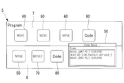
- the program icons (icons) 60, 70, 80 displayed in the first area 6 of the monitor 5 are selected by the input unit 3 and selected in the second area 7. Place the program icons 60 and 80. Then, when the Code icon 80 is selected as the program icon that is the editable program icon (editable program element), a window (third display unit) 50 that displays the contents in the vicinity of the selected Code icon 80 is displayed. Display in a pop-up. Further, as shown in FIG. 7, when the Code icon 80 arranged in the second area 7 is selected, the Code icon 80, which is an editable program icon, may be enlarged and displayed in the area of the first area 6. good.
- a first region 6 for arranging the program blocks 10, 20, 30, and 40 and a third region 8 different from the second region 7 for forming the control program are provided on the monitor 5. It was decided to display the contents of the editable program block when it was selected. Instead, when the CODE block 40, which is an editable program block, is selected as shown in FIG. 8, the selected CODE block 40, which is an editable program block, is enlarged and displayed in the second area 7. A window (third display unit) for displaying the contents may be formed inside the program. The selected program block 40 is indicated by a thick line.
- a window (third display unit) 50 for displaying the contents thereof is pop-up displayed in the vicinity of the selected editable program block 40. You may. Since it is not necessary to provide the third area 8 on the monitor 5 by the enlarged display of the editable program block 40 or the pop-up display of the window 50, a wide display area of the first area 6 and the second area 7 should be secured. Can be done.
- the executed program block 40 becomes another program block. It may be displayed so as to be identifiable by a display mode different from that of 10 and 40. Examples of the identifiable display mode include highlight display, underlined display, framed display, and display with different display colors.
- the program block 40 being executed is an editable program block
- it may include a fourth area (fourth display unit) 9 for displaying the contents of the editable program block 40.
- FIG. 10 shows a case where the fourth region 9 is common to the third region 8, but it may be provided separately.
- the instruction executed in the content displayed in the fourth area 9 is displayed so as to be distinguishable from other instructions. May be good. This makes it possible to visually confirm the program block 40 and / or the instruction being executed.
Landscapes
- Engineering & Computer Science (AREA)
- Software Systems (AREA)
- Theoretical Computer Science (AREA)
- General Engineering & Computer Science (AREA)
- Robotics (AREA)
- General Physics & Mathematics (AREA)
- Physics & Mathematics (AREA)
- Mechanical Engineering (AREA)
- Human Computer Interaction (AREA)
- Manufacturing & Machinery (AREA)
- Automation & Control Theory (AREA)
- Numerical Control (AREA)
- Stored Programmes (AREA)
Abstract
ロボット(100)の制御プログラムを構成する機能をグラフィカルに表す複数種類のプログラム要素を記憶する記憶部(2)と、ユーザによる操作を受け入れる入力部(3)と、記憶部(2)に記憶されているプログラム要素を入力部(3)により選択して配置することにより制御プログラムを生成するプログラム生成部(4)とを備え、プログラム要素の少なくとも1つに、機能を入力部(3)により入力された文字列によって編集可能な可編集プログラム要素を備えるロボット(100)のプログラミング装置(1)である。
Description
本開示は、ロボットのプログラミング装置に関するものである。
ロボットに対する制御プログラムを構成する機能を表すアイコンを組み合わせて配置するロボットのプログラミング装置が知られている(例えば、特許文献1参照。)。
アイコンを組み合わせたプログラムは、初心者には分かり易い反面、高度なプログラムを作成することが困難である。アイコンにはサポートされている命令の数が少ないこと、高度な命令を簡潔にグラフィカルに表現することが困難であること、簡単な命令を多数組み合わせる場合にプログラムが複雑化することなどがその理由である。
したがって、アイコン等のグラフィカルなプログラム要素を用いてプログラミングを容易にしつつ、高度な命令を含むプログラムを作成することができることが望ましい。
したがって、アイコン等のグラフィカルなプログラム要素を用いてプログラミングを容易にしつつ、高度な命令を含むプログラムを作成することができることが望ましい。
本開示の一態様は、ロボットの制御プログラムを構成する機能をグラフィカルに表す複数種類のプログラム要素を記憶する記憶部と、ユーザによる操作を受け入れる入力部と、前記記憶部に記憶されている前記プログラム要素を前記入力部により選択して組み合わせることにより前記制御プログラムを生成するプログラム生成部とを備え、前記プログラム要素の少なくとも1つに、前記機能を前記入力部により入力された文字列によって編集可能な可編集プログラム要素を備えるロボットのプログラミング装置である。
本開示の一実施形態に係るロボットのプログラミング装置1について、図面を参照して以下に説明する。
本実施形態に係るロボット100のプログラミング装置1は、図1に示されるように、例えば、ロボット100を制御する制御装置200に備えられている。プログラミング装置1は制御装置200とは別個に設けられていてもよい。
本実施形態に係るロボット100のプログラミング装置1は、図1に示されるように、例えば、ロボット100を制御する制御装置200に備えられている。プログラミング装置1は制御装置200とは別個に設けられていてもよい。
プログラミング装置1は、後述する複数種類のプログラムブロック(プログラム要素)10,20,30,40を記憶する記憶部2と、ユーザによる操作を受け入れる入力部3と、プログラム生成部4とを備えている。
記憶部2はメモリであり、入力部3はキーボードおよびマウス、タッチパネル等の入力装置である。
記憶部2はメモリであり、入力部3はキーボードおよびマウス、タッチパネル等の入力装置である。
プログラム生成部4は、プロセッサおよびモニタ5を備えており、記憶部2に記憶されているプログラムブロック10,20,30,40をモニタ5に表示し、入力部3により選択して組み合わせることにより制御プログラムを生成する。
プログラム生成部4は、図2に示されるように、モニタ5上に、第1領域(第1表示部)6と、第2領域(第2表示部)7と、第3領域(第3表示部)8とを形成する。第1領域6には、記憶部2に記憶されているプログラムブロック10,20,30,40が、入力部3によって選択可能に表示される。
第1領域6に表示されたプログラムブロック10,20,30,40を、入力部3、例えば、マウスにより選択すると、選択されたプログラムブロック10が複製される(選択されたプログラムブロック10にハッチングが付されている)。複製されたプログラムブロック10をマウスにより把持して、図3に示されるように、ドラッグアンドドロップにより第2領域7に配置することによって、他のプログラムブロック20,30,40に組み合わせられて制御プログラムが構成される。
プログラム要素の多くは、ロボット100の制御プログラムを構成する機能をグラフィカルに表すものであり、設定可能なパラメータを有し、単純な機能を実現可能な編集不可能な要素である。例えば、プログラムブロックの1つであるMOVEブロック10は、ロボット100のTCP(ツール先端点)を目標位置に移動させるようロボット100を動作させる要素である。
MOVEブロック10は、図4に示されるように、パラメータとして、例えば、他のプログラムブロックである目標位置ブロック20および通過点ブロック30を組み合わせ可能である。各プログラムブロック10,20,30,40にはジグソーパズルの凹凸のような接続部11,12,13,21,22,31,32,41,42が設けられ、一のプログラムブロック10,20,30,40の凹形状の接続部11,12,21,31,41に他のプログラムブロック10,20,30,40の凸形状の接続部13,22,32,42を接続することができる。
目標位置ブロック20は、MOVEブロック10に組み合わせられることにより、MOVEブロック10によってTCPを移動させる目標位置を設定することができる。通過点ブロック30は、目標位置ブロック20とともにMOVEブロック10に組み合わせられることにより、TCPを現在位置から目標位置まで移動させる間における通過点を設定することができる。目標位置ブロック20および通過点ブロック30は、パラメータとして位置座標を設定可能である。
本実施形態に係るロボット100のプログラミング装置1は、プログラムブロック10,20,30,40の少なくとも1つに、制御プログラムを構成する機能を、入力部3により入力された文字列によって編集可能な可編集プログラムブロック(可編集プログラム要素)を備えている。可編集プログラムブロックも他のプログラムブロックと同様に、第1領域6に表示されており、例えばマウスにより選択して、ドラッグアンドドロップにより第2領域7に配置することができる。
例えば、可編集プログラムブロックの1つであるCODEブロック40は、図5に示されるように、モニタ5上の第1領域6あるいは第2領域7に表示された状態で入力部3により選択されることにより、その内容が第3領域8に編集可能に表示される。
すなわち、可編集プログラムブロックが選択されると、モニタ5上の第3領域8に内容が表示される。可編集プログラムブロックに内容が登録されていない場合には、第3領域8は空白の状態である。
すなわち、可編集プログラムブロックが選択されると、モニタ5上の第3領域8に内容が表示される。可編集プログラムブロックに内容が登録されていない場合には、第3領域8は空白の状態である。
可編集プログラムブロックには、複雑な命令を記述できる。複雑な命令としては、例えば、補間命令あるいは条件分岐命令などを挙げることができる。
また、可編集プログラムブロックには、複数の命令を記述できる。例えば、複数の動作などを1つのプログラムブロック内に記述することができる。
ユーザは入力部3、例えば、キーボードを用いて、所定のプログラム言語に従い、制御プログラムを構成する機能を文字列によって入力していくことができる。内容が編集されたCODEブロック40は、新たな名前を付して、第1領域6にドラッグアンドドロップすることにより、プログラムブロック10,20,30,40の1つとして登録することができる。
この操作を繰り返すことにより、第2領域7に制御プログラムを生成することができる。生成された制御プログラムは記憶部2に記憶される。制御装置200に備えられた制御部210は、記憶部2に記憶されている制御プログラムを読み出して、動作制御信号を生成し、ロボット100に出力する。
このように構成された本実施形態に係るロボット100のプログラミング装置1によれば、第1領域6に表示されたプログラムブロックを選択して第2領域7に配列するだけで、制御プログラムを作成することができる。そして、配列するプログラムブロック10,20,30,40の1以上を可編集プログラムブロック(ここでは、CODEブロック40)とすることにより、単純なプログラムブロックでは表現することが困難な高度な命令を制御プログラムに含めることができるという利点がある。
なお、本実施形態においては、ロボット100の制御プログラムを構成する機能をグラフィカルに表すプログラム要素として、プログラムブロック10,20,30,40を例示したが、これに代えて、アイコンを採用してもよい。アイコンを所定の順序に従って配列することにより、プログラムブロック10,20,30,40と同様に機能させることができる。
具体的には、図6に示されるように、モニタ5の第1領域6に表示されたプログラムアイコン(アイコン)60,70,80を入力部3によって選択して、第2領域7に選択したプログラムアイコン60,80を配置する。そして、可編集プログラムアイコン(可編集プログラム要素)であるプログラムアイコンとしてCodeアイコン80が選択されたときに、選択されたCodeアイコン80の近傍にその内容を表示するウインドウ(第3表示部)50をポップアップ表示する。また、図7に示されるように、第2領域7に配置されたCodeアイコン80が選択されたときに、第1領域6の領域に可編集プログラムアイコンであるCodeアイコン80を拡大表示してもよい。
また、本実施形態においては、モニタ5上に、プログラムブロック10,20,30,40を配列する第1領域6および制御プログラムを形成する第2領域7とは別の第3領域8を設け、可編集プログラムブロックが選択された場合にその内容を表示することとした。これに代えて、図8に示されるように可編集プログラムブロックであるCODEブロック40が選択されたときに、選択された可編集プログラムブロックであるCODEブロック40を第2領域7内において拡大表示してその内部に内容を表示するウインドウ(第3表示部)を形成してもよい。選択されたプログラムブロック40は太線で表示している。
また、可編集プログラムブロック40が選択されたときに、図9に示されるように、選択された可編集プログラムブロック40の近傍にその内容を表示するウインドウ(第3表示部)50をポップアップ表示してもよい。可編集プログラムブロック40の拡大表示またはウインドウ50のポップアップ表示により、モニタ5上に第3領域8を設けておく必要がないので、第1領域6および第2領域7の表示面積を広く確保することができる。
また、生成された制御プログラムを実行すると、図10に示されるように、第2領域7に配列された複数のプログラムブロック10,40の内、実行されているプログラムブロック40が、他のプログラムブロック10,40とは異なる表示態様によって識別可能に表示されることにしてもよい。識別可能な表示態様としては、例えば、ハイライト表示、下線を付した表示、枠で囲んだ表示、あるいは表示色を異ならせた表示などを挙げることができる。
そして、実行されているプログラムブロック40が、可編集プログラムブロックである場合には、可編集プログラムブロック40の内容を表示する第4領域(第4表示部)9を備えていてもよい。図10は、第4領域9が第3領域8と共通している場合を示しているが、別個に設けてもよい。
さらに、可編集プログラムブロック40が実行されている場合には、図10に示されるように、第4領域9に表示された内容において実行されている命令が他の命令から識別可能に表示されてもよい。
これにより、実行されているプログラムブロック40および/または命令を視覚的に確認することができる。
さらに、可編集プログラムブロック40が実行されている場合には、図10に示されるように、第4領域9に表示された内容において実行されている命令が他の命令から識別可能に表示されてもよい。
これにより、実行されているプログラムブロック40および/または命令を視覚的に確認することができる。
1 プログラミング装置
2 記憶部
3 入力部
4 プログラム生成部
6 第1領域(第1表示部)
7 第2領域(第2表示部)
8 第3領域(第3表示部)
9 第4領域(第4表示部)
10 MOVEブロック(プログラムブロック、プログラム要素)
20 目標位置ブロック(プログラムブロック、プログラム要素)
30 通過点ブロック(プログラムブロック、プログラム要素)
40 CODEブロック(プログラムブロック、プログラム要素、可編集プログラムブロック、可編集プログラム要素)
50 ウインドウ(第3表示部)
60 MOVEアイコン(プログラム要素)
70 MOVE2アイコン(プログラム要素)
80 Codeアイコン(プログラム要素、可編集プログラムアイコン、可編集プログラム要素)
100 ロボット
Claims (7)
- ロボットの制御プログラムを構成する機能をグラフィカルに表す複数種類のプログラム要素を記憶する記憶部と、
ユーザによる操作を受け入れる入力部と、
前記記憶部に記憶されている前記プログラム要素を前記入力部により選択して配置することにより前記制御プログラムを生成するプログラム生成部とを備え、
前記プログラム要素の少なくとも1つに、前記機能を前記入力部により入力された文字列によって編集可能な可編集プログラム要素を備えるロボットのプログラミング装置。 - 前記プログラム生成部が、前記記憶部に記憶されている前記プログラム要素を前記入力部により選択可能に表示する第1表示部と、該第1表示部に表示された前記プログラム要素の内、選択された前記プログラム要素を複製して配列し、前記入力部により選択可能に表示する第2表示部と、前記第1表示部または前記第2表示部に配列された前記プログラム要素の内、前記可編集プログラム要素が選択されたときに、その内容を前記入力部により編集可能に表示する第3表示部とを備える請求項1に記載のロボットのプログラミング装置。
- 前記第3表示部が、選択された前記可編集プログラム要素内に生成される請求項2に記載のロボットのプログラミング装置。
- 前記第3表示部が、選択された前記可編集プログラム要素の近傍にポップアップ表示される請求項2に記載のロボットのプログラミング装置。
- 前記プログラム生成部により生成された前記制御プログラムを実行すると、
前記第2表示部に配列された複数の前記プログラム要素の内、実行されている前記プログラム要素が、他の前記プログラム要素から識別可能に表示される請求項2から請求項4のいずれかに記載のロボットのプログラミング装置。 - 実行されている前記プログラム要素が、前記可編集プログラム要素である場合に、該可編集プログラム要素の内容を表示する第4表示部を備える請求項5に記載のロボットのプログラミング装置。
- 前記可編集プログラム要素が実行されている場合に、前記第4表示部に表示された前記内容において実行されている命令が他の命令から識別可能に表示される請求項6に記載のロボットのプログラミング装置。
Priority Applications (5)
| Application Number | Priority Date | Filing Date | Title |
|---|---|---|---|
| CN202080101554.4A CN115697646A (zh) | 2020-06-01 | 2020-06-01 | 机器人的编程装置 |
| JP2022529146A JPWO2021245746A1 (ja) | 2020-06-01 | 2020-06-01 | |
| US17/928,387 US20230099469A1 (en) | 2020-06-01 | 2020-06-01 | Robot programming device |
| PCT/JP2020/021601 WO2021245746A1 (ja) | 2020-06-01 | 2020-06-01 | ロボットのプログラミング装置 |
| DE112020006874.9T DE112020006874T5 (de) | 2020-06-01 | 2020-06-01 | Roboterprogrammierungsvorrichtung |
Applications Claiming Priority (1)
| Application Number | Priority Date | Filing Date | Title |
|---|---|---|---|
| PCT/JP2020/021601 WO2021245746A1 (ja) | 2020-06-01 | 2020-06-01 | ロボットのプログラミング装置 |
Publications (1)
| Publication Number | Publication Date |
|---|---|
| WO2021245746A1 true WO2021245746A1 (ja) | 2021-12-09 |
Family
ID=78830940
Family Applications (1)
| Application Number | Title | Priority Date | Filing Date |
|---|---|---|---|
| PCT/JP2020/021601 WO2021245746A1 (ja) | 2020-06-01 | 2020-06-01 | ロボットのプログラミング装置 |
Country Status (5)
| Country | Link |
|---|---|
| US (1) | US20230099469A1 (ja) |
| JP (1) | JPWO2021245746A1 (ja) |
| CN (1) | CN115697646A (ja) |
| DE (1) | DE112020006874T5 (ja) |
| WO (1) | WO2021245746A1 (ja) |
Cited By (1)
| Publication number | Priority date | Publication date | Assignee | Title |
|---|---|---|---|---|
| WO2023162164A1 (ja) * | 2022-02-25 | 2023-08-31 | 三菱電機株式会社 | 教示支援装置、作業システム、教示支援方法および教示支援プログラム |
Citations (5)
| Publication number | Priority date | Publication date | Assignee | Title |
|---|---|---|---|---|
| JPH04507022A (ja) * | 1989-10-17 | 1992-12-03 | アプライド バイオシステムズ インコーポレイテッド | ロボットインターフェース |
| JPH08249026A (ja) * | 1995-03-10 | 1996-09-27 | Fanuc Ltd | ロボットを含むシステムのプログラミング方法 |
| JP2003067007A (ja) * | 2001-08-27 | 2003-03-07 | Mitsubishi Electric Corp | エンジニアリングツール及びエンジニアリングシステム |
| US20070150102A1 (en) * | 2005-12-09 | 2007-06-28 | Joong Ki Park | Method of supporting robot application programming and programming tool for the same |
| WO2020012558A1 (ja) * | 2018-07-10 | 2020-01-16 | 三菱電機株式会社 | 教示装置 |
Family Cites Families (2)
| Publication number | Priority date | Publication date | Assignee | Title |
|---|---|---|---|---|
| JP2001353678A (ja) * | 2000-06-12 | 2001-12-25 | Sony Corp | オーサリング・システム及びオーサリング方法、並びに記憶媒体 |
| JP7440227B2 (ja) * | 2019-08-28 | 2024-02-28 | ファナック株式会社 | ロボットプログラミング装置及びロボットプログラミング方法 |
-
2020
- 2020-06-01 WO PCT/JP2020/021601 patent/WO2021245746A1/ja active Application Filing
- 2020-06-01 CN CN202080101554.4A patent/CN115697646A/zh active Pending
- 2020-06-01 DE DE112020006874.9T patent/DE112020006874T5/de active Pending
- 2020-06-01 JP JP2022529146A patent/JPWO2021245746A1/ja active Pending
- 2020-06-01 US US17/928,387 patent/US20230099469A1/en active Pending
Patent Citations (5)
| Publication number | Priority date | Publication date | Assignee | Title |
|---|---|---|---|---|
| JPH04507022A (ja) * | 1989-10-17 | 1992-12-03 | アプライド バイオシステムズ インコーポレイテッド | ロボットインターフェース |
| JPH08249026A (ja) * | 1995-03-10 | 1996-09-27 | Fanuc Ltd | ロボットを含むシステムのプログラミング方法 |
| JP2003067007A (ja) * | 2001-08-27 | 2003-03-07 | Mitsubishi Electric Corp | エンジニアリングツール及びエンジニアリングシステム |
| US20070150102A1 (en) * | 2005-12-09 | 2007-06-28 | Joong Ki Park | Method of supporting robot application programming and programming tool for the same |
| WO2020012558A1 (ja) * | 2018-07-10 | 2020-01-16 | 三菱電機株式会社 | 教示装置 |
Cited By (1)
| Publication number | Priority date | Publication date | Assignee | Title |
|---|---|---|---|---|
| WO2023162164A1 (ja) * | 2022-02-25 | 2023-08-31 | 三菱電機株式会社 | 教示支援装置、作業システム、教示支援方法および教示支援プログラム |
Also Published As
| Publication number | Publication date |
|---|---|
| US20230099469A1 (en) | 2023-03-30 |
| JPWO2021245746A1 (ja) | 2021-12-09 |
| DE112020006874T5 (de) | 2022-12-29 |
| CN115697646A (zh) | 2023-02-03 |
Similar Documents
| Publication | Publication Date | Title |
|---|---|---|
| CN109605366B (zh) | 机器人图形化编程交互系统及机器人 | |
| JP2007242054A (ja) | ロボット言語処理装置 | |
| WO1998040817A1 (fr) | Methode et systeme de programmation visuelle | |
| JP6469162B2 (ja) | ロボットのオフライン教示装置 | |
| JP5823036B2 (ja) | 溶接用電源、溶接用電源のインターフェースを環境設定するための方法、及びコンピュータプログラム製品 | |
| JP2020146759A (ja) | 制御装置およびロボットシステム | |
| JP4322770B2 (ja) | 画面作成装置、画面作成プログラムおよびそれを記録した記録媒体 | |
| EP0745927B1 (en) | Method of and editing system for setting tool button | |
| JP5458616B2 (ja) | ロボット制御命令入力装置 | |
| WO2021245746A1 (ja) | ロボットのプログラミング装置 | |
| CN110936354A (zh) | 机器人的程序创建辅助装置 | |
| JP2005182125A (ja) | グラフ表示制御装置及びプログラム | |
| JP2006130577A (ja) | ロボット制御装置およびロボットシステム | |
| JP2009026239A (ja) | Gui編集装置、gui編集方法およびプログラム | |
| WO2022153938A1 (ja) | ロボット教示装置及びロボットプログラムの生成用プログラム | |
| TWI569118B (zh) | 畫面作成軟體 | |
| JPH10291183A (ja) | ロボット言語処理装置 | |
| JP2023080596A (ja) | プログラム作成装置およびプログラム | |
| KR20130040925A (ko) | 프로그램 작성 장치 및 화상 제어 시스템 | |
| JP2010160655A (ja) | 情報処理装置およびオブジェクト設定方法 | |
| JP7436796B2 (ja) | ロボットのプログラム作成支援装置 | |
| JP3363056B2 (ja) | プログラマブル表示装置 | |
| JP2003039357A (ja) | ロボットの教示装置 | |
| JP7220531B2 (ja) | 画面作成装置 | |
| CN117349917B (zh) | 一种施工方案模拟系统、方法以及存储介质 |
Legal Events
| Date | Code | Title | Description |
|---|---|---|---|
| 121 | Ep: the epo has been informed by wipo that ep was designated in this application |
Ref document number: 20939158 Country of ref document: EP Kind code of ref document: A1 |
|
| ENP | Entry into the national phase |
Ref document number: 2022529146 Country of ref document: JP Kind code of ref document: A |
|
| 122 | Ep: pct application non-entry in european phase |
Ref document number: 20939158 Country of ref document: EP Kind code of ref document: A1 |