WO2023157466A1 - 硬質皮膜 - Google Patents
硬質皮膜 Download PDFInfo
- Publication number
- WO2023157466A1 WO2023157466A1 PCT/JP2022/047417 JP2022047417W WO2023157466A1 WO 2023157466 A1 WO2023157466 A1 WO 2023157466A1 JP 2022047417 W JP2022047417 W JP 2022047417W WO 2023157466 A1 WO2023157466 A1 WO 2023157466A1
- Authority
- WO
- WIPO (PCT)
- Prior art keywords
- composition
- atomic ratio
- layer
- upper layer
- hard coating
- Prior art date
- Legal status (The legal status is an assumption and is not a legal conclusion. Google has not performed a legal analysis and makes no representation as to the accuracy of the status listed.)
- Ceased
Links
Images





Classifications
-
- C—CHEMISTRY; METALLURGY
- C23—COATING METALLIC MATERIAL; COATING MATERIAL WITH METALLIC MATERIAL; CHEMICAL SURFACE TREATMENT; DIFFUSION TREATMENT OF METALLIC MATERIAL; COATING BY VACUUM EVAPORATION, BY SPUTTERING, BY ION IMPLANTATION OR BY CHEMICAL VAPOUR DEPOSITION, IN GENERAL; INHIBITING CORROSION OF METALLIC MATERIAL OR INCRUSTATION IN GENERAL
- C23C—COATING METALLIC MATERIAL; COATING MATERIAL WITH METALLIC MATERIAL; SURFACE TREATMENT OF METALLIC MATERIAL BY DIFFUSION INTO THE SURFACE, BY CHEMICAL CONVERSION OR SUBSTITUTION; COATING BY VACUUM EVAPORATION, BY SPUTTERING, BY ION IMPLANTATION OR BY CHEMICAL VAPOUR DEPOSITION, IN GENERAL
- C23C14/00—Coating by vacuum evaporation, by sputtering or by ion implantation of the coating forming material
- C23C14/06—Coating by vacuum evaporation, by sputtering or by ion implantation of the coating forming material characterised by the coating material
- C23C14/0641—Nitrides
-
- B—PERFORMING OPERATIONS; TRANSPORTING
- B23—MACHINE TOOLS; METAL-WORKING NOT OTHERWISE PROVIDED FOR
- B23B—TURNING; BORING
- B23B27/00—Tools for turning or boring machines; Tools of a similar kind in general; Accessories therefor
- B23B27/14—Cutting tools of which the bits or tips or cutting inserts are of special material
-
- C—CHEMISTRY; METALLURGY
- C23—COATING METALLIC MATERIAL; COATING MATERIAL WITH METALLIC MATERIAL; CHEMICAL SURFACE TREATMENT; DIFFUSION TREATMENT OF METALLIC MATERIAL; COATING BY VACUUM EVAPORATION, BY SPUTTERING, BY ION IMPLANTATION OR BY CHEMICAL VAPOUR DEPOSITION, IN GENERAL; INHIBITING CORROSION OF METALLIC MATERIAL OR INCRUSTATION IN GENERAL
- C23C—COATING METALLIC MATERIAL; COATING MATERIAL WITH METALLIC MATERIAL; SURFACE TREATMENT OF METALLIC MATERIAL BY DIFFUSION INTO THE SURFACE, BY CHEMICAL CONVERSION OR SUBSTITUTION; COATING BY VACUUM EVAPORATION, BY SPUTTERING, BY ION IMPLANTATION OR BY CHEMICAL VAPOUR DEPOSITION, IN GENERAL
- C23C14/00—Coating by vacuum evaporation, by sputtering or by ion implantation of the coating forming material
- C23C14/06—Coating by vacuum evaporation, by sputtering or by ion implantation of the coating forming material characterised by the coating material
-
- C—CHEMISTRY; METALLURGY
- C23—COATING METALLIC MATERIAL; COATING MATERIAL WITH METALLIC MATERIAL; CHEMICAL SURFACE TREATMENT; DIFFUSION TREATMENT OF METALLIC MATERIAL; COATING BY VACUUM EVAPORATION, BY SPUTTERING, BY ION IMPLANTATION OR BY CHEMICAL VAPOUR DEPOSITION, IN GENERAL; INHIBITING CORROSION OF METALLIC MATERIAL OR INCRUSTATION IN GENERAL
- C23C—COATING METALLIC MATERIAL; COATING MATERIAL WITH METALLIC MATERIAL; SURFACE TREATMENT OF METALLIC MATERIAL BY DIFFUSION INTO THE SURFACE, BY CHEMICAL CONVERSION OR SUBSTITUTION; COATING BY VACUUM EVAPORATION, BY SPUTTERING, BY ION IMPLANTATION OR BY CHEMICAL VAPOUR DEPOSITION, IN GENERAL
- C23C14/00—Coating by vacuum evaporation, by sputtering or by ion implantation of the coating forming material
- C23C14/22—Coating by vacuum evaporation, by sputtering or by ion implantation of the coating forming material characterised by the process of coating
- C23C14/24—Vacuum evaporation
- C23C14/32—Vacuum evaporation by explosion; by evaporation and subsequent ionisation of the vapours, e.g. ion-plating
- C23C14/325—Electric arc evaporation
Definitions
- the present invention relates to a hard coating formed on a substrate.
- press dies and cutting tools coated with nitrides such as TiN, TiAlN and CrAlN have been put into practical use.
- the workpieces machined by the press dies, cutting tools, etc. have become difficult to cut and difficult to machine, and the machining conditions are required to be highly efficient.
- press dies and cutting tools are required to have a longer life without being shortened even if they are processed under more severe processing conditions.
- Hard coatings formed on the surfaces of dies and cutting tools are required to have higher durability and performance.
- Abrasion resistance and heat resistance are important for this durability film performance.
- High wear resistance means less wear of the hard coating during cutting or press working with a die.
- High heat resistance means that oxidation of the surface is less likely to occur up to higher temperatures when molds or cutting tools reach high temperatures during processing.
- coating performance includes high adhesion resistance and low coefficient of friction, which affect the surface and surface properties of the workpiece during processing and improve releasability.
- Patent Document 1 In order to improve heat resistance, there is a study of the properties of a TiAlN single layer film (Patent Document 1), and a comparison of a TiAlN coating and a CrAlN coating in consideration of the substrate (Patent Document 2).
- Patent Document 3 TiCrAlN coatings
- Patent Document 4 Si-added AlTiSiN coatings
- Patent Document 5 AlCrSiN coatings
- Patent Document 6 a TiCrAlYN coating with excellent sliding properties has been proposed as a coating for cold dies used at 600° C. or lower.
- Patent Document 7 discloses a laminated film of TiAlN and TiVN films in order to exhibit wear resistance, adhesion resistance and lubrication effect of cutting tools.
- Patent Document 8 discloses a film in which a TiSiN film and a TiAlN film are laminated.
- Patent Document 9 discloses a two-layer film in which a TiCrAlSiYN film with high oxidation resistance and high strength and a TiCrAlN film with high toughness are laminated.
- Patent Document 10 discloses that a film in which an AlSiVCrN film is laminated as an upper layer and an AlCrN film is laminated as a lower layer improves heat resistance in addition to wear resistance and sliding properties.
- Patent Document 11 discloses a CrAlTiY layer with a Cr ratio of more than 65% as a wear-resistant layer for cutting tools.
- the present invention has been made in view of such problems, and an object of the present invention is to provide a hard coating with improved wear resistance, heat resistance, low friction/high sliding properties, adhesion resistance, and adhesion. .
- One embodiment of the hard coating includes a lower layer having a composition of (Ti, Al) N or (Ti, Al, Mo) N, an intermediate layer formed on the lower layer, and a layer formed on the intermediate layer.
- an upper layer having a composition of (Al, Ti, Cr, M)N, wherein M is one or more elements selected from Mo, V and Y, and the intermediate layer is substantially composed of is composed of (Al, Ti, Cr, M)N, and has a composition between the composition of the lower layer and the composition of the upper layer, and the atomic ratio of Al and the atomic ratio of Ti in the film thickness direction and M change from the lower layer side to the upper layer side, and the Cr atomic ratio in the film thickness direction increases toward the upper layer side.
- the hard coating it is possible to provide a hard coating with improved wear resistance, heat resistance, low friction/high sliding properties, adhesion resistance, and adhesion.
- FIG. 4 is a diagram for explaining another example of the first basic configuration of the embodiment of the hard coating; It is a figure for demonstrating the 2nd basic structure of embodiment of a hard coating. It is a figure for demonstrating the 3rd basic structure of embodiment of a hard coating. It is a figure for demonstrating an example of the 10th basic structure of embodiment of a hard coating.
- FIG. 10 is a diagram for explaining another example of the tenth basic configuration of the embodiment of the hard coating; It is a top view which shows schematic structure of an example of a hard film deposition apparatus. It is a front view which shows schematic structure of an example of a hard film deposition apparatus. It is a graph showing the X-ray diffraction analysis result of one hard coating.
- the substantial composition of the intermediate layer means the average composition of the intermediate layer in the entire film thickness direction.
- the composition between the composition of the lower layer and the composition of the upper layer means that the atomic ratio of each component is a value between the composition of the lower layer and the composition of the upper layer.
- the intermediate layer may be a film obtained by alternately laminating a film having the same composition as the upper layer and a film having the same composition as the lower layer.
- Another embodiment of the hard coating comprises a lower layer having a composition of (Ti,Al)N or (Ti,Al,Mo)N, an intermediate layer formed on the lower layer, and formed on the intermediate layer.
- the upper layer has a composition of (Al 1-yza Ti y Cr z M a )N, where 0 ⁇ y ⁇ 0.45, 0 ⁇ z ⁇ 0.5, 0 ⁇ a ⁇ 0.02 (where y, z, and a all represent atomic ratios) may be satisfied.
- the lower layer has a composition of 0.4 ⁇ x ⁇ 0.70 and 0 ⁇ b ⁇ 0.10 (where x , b each represent an atomic ratio).
- the M is Y, for example.
- the atomic ratio of M among Al, Ti, Cr, M, and N contained in the entire hard coating may be less than 0.01.
- Yet another embodiment of the hard coating is a hard coating formed on a substrate, comprising a lower layer having a composition of (Ti,Al)N or (Ti,Al,Mo)N; and an upper layer having a composition of (Al, Ti, Cr, M)N, wherein M is one or more elements selected from Mo, V and Y, and the hard coating
- the atomic ratio of M among Al, Ti, Cr, M and N contained in the whole is less than 0.01.
- the lower layer has a composition of 0.4 ⁇ x ⁇ 0.70 and 0 ⁇ b ⁇ 0.10 (wherein the composition is expressed as ( Ti1- xAlxMob )N) , x and b each represent an atomic ratio), and the upper layer has a composition of (Al 1-yza Ti y Cr z M a )N where 0 ⁇ y ⁇ 0.45, 0 ⁇ z ⁇ 0.5, 0 ⁇ a ⁇ 0.02 (where y, z, and a all represent atomic ratios) may be satisfied.
- the (111)/ ⁇ (111)+(200)+(220) ⁇ orientation by X-ray diffraction analysis may be 50% or more in the entire film.
- Still another embodiment of the hard coating is a hard coating in which the upper layer constituting the outermost surface layer has a composition of (Al, Ti, Cr, M)N, wherein M is selected from Mo, V and Y. (111)/ ⁇ (111)+(200)+(220) ⁇ orientation by X-ray diffraction analysis is 50% or more in the entire film.
- the upper layer has a composition of (Al 1-yza Ti y Cr z M a )N where 0 ⁇ y ⁇ 0.45, 0 ⁇ z ⁇ 0.5, 0 ⁇ a ⁇ 0.02 (where y, z, and a all represent atomic ratios) may be satisfied.
- a substantial composition is (Al, Ti, Cr, M)N or (Al, Ti, Cr, Mo, M)N, and the composition of the upper layer is and the composition of the lower layer.
- the intermediate layer may have an atomic ratio of Al in the film thickness direction increasing from the lower layer side toward the upper layer side. Further, the rate of increase in the atomic ratio of Al may be higher in the upper half of the intermediate layer than in the lower layer.
- the Al atomic ratio in the film thickness direction decreases from the lower layer side to the upper layer side, or the Al atomic ratio in the film thickness direction is uniform.
- the half of the intermediate layer on the upper layer side has an Al A reduction rate of the atomic ratio may be larger than that of the lower layer side half.
- the intermediate layer may have a Ti atomic ratio in the film thickness direction that decreases from the lower layer side toward the upper layer side. Further, the reduction rate of the atomic ratio of Ti in the upper layer side half of the intermediate layer may be higher than in the lower layer side half.
- the rate of increase in the atomic ratio of Cr in the half of the intermediate layer on the upper layer side may be higher than that in the half of the intermediate layer on the lower layer side.
- the lower layer has a composition of (Ti,Al)N, and when the composition is represented by (Ti 1-x Al x )N, 0.4 ⁇ x ⁇ 0.70 (where x is an atomic ratio), and in the intermediate layer, the atomic ratio of M in the thickness direction increases from the lower layer side toward the upper layer side. In this case, the rate of increase in the atomic ratio of M may be higher in the upper half of the intermediate layer than in the lower layer.
- the lower layer has a composition of (Ti, Al, Mo)N, and when the composition is represented by (Ti 1-x Al x Mo b )N, 0.4 ⁇ x ⁇ 0.70, 0 ⁇ b ⁇ 0.05 (where x and b both represent atomic ratios) is satisfied, M is one or more elements selected from V and Y, and the intermediate layer has a thickness of The atomic ratio of Mo decreases from the lower layer side to the upper layer side, while the atomic ratio of M in the film thickness direction increases from the lower layer side to the upper layer side. may In this case, in the upper half of the intermediate layer, even if the Mo atomic ratio decrease rate and the M atomic ratio increase rate are each larger than the lower layer side half. good.
- compositions of the intermediate layer and the upper layer in the above embodiment are (Al,Ti,Cr,Mo)N, (Al,Ti,Cr,V)N, (Al,Ti,Cr,Y)N, (Al,Ti , Cr, Mo, V) N, (Al, Ti, Cr, Mo, Y) N, (Al, Ti, Cr, V, Y) N, or (Al, Ti, Cr, Mo, V, Y) N is.
- Still another embodiment of the hard coating comprises a lower layer having a composition of (Ti,Al)N or (Ti,Al,Mo)N, an intermediate layer formed on the lower layer, and an upper layer having a composition of (Al, M1, M)N, wherein M1 is an element selected from Ti and Cr, and M is selected from Mo, V and Y one or more selected elements, substantially composed of (Al, Ti, M1, M)N between the upper layer and the lower layer, and the composition of the upper layer and the lower layer and an intermediate layer having a composition intermediate to the composition of be.
- the composition of the top layer in this embodiment is (Al,Ti,Mo)N, (Al,Ti,V)N, (Al,Ti,Y)N, (Al,Ti,Mo,V)N, (Al , Ti, Mo, Y) N, (Al, Ti, V, Y) N, (Al, Ti, Mo, V, Y) N, (Al, Cr, Mo) N, (Al, Cr, V) N , (Al, Cr, Y) N, (Al, Cr, Mo, V) N, (Al, Cr, Mo, Y) N, (Al, Cr, V, Y) N, (Al, Cr, Mo, V,Y)N, preferably (Al,Ti,Mo)N, (Al,Ti,V)N, (Al,Cr,Mo)N, (Al,Cr,V)N.
- the intermediate layer may be a film in which a film having the same composition as the upper layer and a film having the same composition as the lower layer are alternately laminated.
- the upper layer has a composition of (Al 1-ac M1 c M a )N, where 0 ⁇ c ⁇ 0.5 and 0 ⁇ a ⁇ 0.02 (where a , c each represent an atomic ratio, and either y or z may satisfy 0).
- the rate of increase in the atomic ratio of Al in the upper layer side half of the intermediate layer may be higher than that in the lower layer side half.
- the atomic ratio of M among Al, Ti, M1, M, and N contained in the hard coating as a whole is less than 0.01.
- the intermediate layer may have an Al atomic ratio in the film thickness direction that increases from the lower layer side toward the upper layer side.
- the rate of increase in the atomic ratio of Al in the half of the intermediate layer on the upper layer side is higher than that in the half on the lower layer side.
- the intermediate layer may have an atomic ratio of at least one of M1 and M in the film thickness direction that increases or decreases from the lower layer side to the upper layer side.
- the atomic ratio of at least one of M1 and M in the film thickness direction of the intermediate layer is the ratio of Cr, Ti, Mo, V, and Y in the upper layer from the lower layer side to the upper layer side. You may make it change so that an atomic ratio may be approached. Further, the rate of change in the atomic ratio of at least one of M1 and M may be greater in the upper half of the intermediate layer than in the lower half.
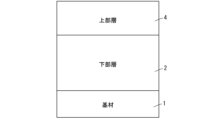
- FIG. 1 and 2 are diagrams for explaining the first basic configuration, respectively, the left diagram is a schematic cross-sectional view, and the right diagram is a graph showing the atomic ratio of each composition in the film thickness direction. 1 and 2, the vertical axis indicates the film thickness and the horizontal axis indicates the atomic ratio (arbitrary unit).
- FIG. 3 is a schematic cross-sectional view for explaining the second basic configuration.
- FIG. 4 is a schematic cross-sectional view for explaining the third basic configuration. 1 to 4 schematically show an example of the film thickness ratio of each layer, and the film thickness ratio of each film constituting the first basic configuration is shown in FIG. ⁇ is not limited to that shown in FIG.
- the first basic configuration of the hard coating consists of a lower layer 2 formed on a substrate 1, an intermediate layer 3 formed on the lower layer 2, and and an upper layer 4 formed thereon.
- the lower layer 2 has a composition of (Ti,Al)N.
- the upper layer 4 has a composition of (Al, Ti, Cr, Y)N.
- the intermediate layer 3 consists essentially of (Al, Ti, Cr, Y)N and has a composition between that of the lower layer 2 and that of the upper layer 4 .
- the Al atomic ratio and the Ti atomic ratio in the film thickness direction change from the lower layer 2 side toward the upper layer 4 side.
- the atomic ratio of Al and the atomic ratio of Ti in the film thickness direction of the intermediate layer 3 change from the lower layer 2 side to the upper layer 4 side
- the Al atomic ratio and the Ti atomic ratio of the upper layer 4 It changes so as to approach the ratio.
- the atomic ratio of Cr and the atomic ratio of Y in the film thickness direction increase toward the upper layer 4 side.
- the upper layer 4 contacts the work during working and receives sliding and pressure at high temperature. , subject to wear and high temperature oxidation.
- the upper layer 4 made of (Al, Ti, Cr, Y)N has extremely excellent wear resistance and oxidation resistance, and the durability of the entire hard coating is extremely high.
- the hard coating of the first basic configuration suppresses a change in the composition of the upper layer 4 and maintains its durability. Therefore, according to the hard coating of the first basic configuration, the life of the hard coating is extended, and it has a long life and is excellent in wear resistance, heat resistance, low friction / high sliding characteristics, adhesion resistance, adhesion, etc. A hard film is obtained.
- the hard coating having the first basic configuration can remarkably improve processing performance such as press die processing and cutting.
- the atomic ratios of Al, Ti, Cr, and Y in the intermediate layer 3 change in the film thickness direction from the lower layer 2 side to the upper layer 4 side as described above.
- the adhesive force at the interface between the substrate 1, the lower layer 2, and the upper layer 4 is stabilized, and by changing the composition, the toughness required for the lower layer 2 and the toughness required for the upper layer 4 are increased.
- Excellent wear resistance, heat resistance and durability can be exhibited by more effectively exhibiting the wear resistance and heat resistance that are required.
- the intermediate layer 3 whose composition changes in the film thickness direction uses a plurality of targets by, for example, an arc ion plating method or a reactive sputtering method, and alternately laminates films formed by those targets. At least one of the targets can be used to form a film having a different film thickness between the lower layer side and the upper layer side.
- the rate of increase in the atomic ratio of Al in the half of the intermediate layer 3 on the upper layer 4 side may be higher than that in the half on the lower layer 2 side.
- the reduction rate of the atomic ratio of Ti may be larger than in the half on the lower layer 2 side.
- the Al atomic ratio in the film thickness direction may decrease from the lower layer 2 side to the upper layer 4 side (see FIG. 2), or may have a uniform atomic ratio of Al.
- the atomic ratio of Ti in the film thickness direction may increase from the side of the lower layer 2 toward the side of the upper layer 4, or the atomic ratio of Ti in the film thickness direction may be increased. may be uniform.
- the rate of increase in the atomic ratio of Cr in the half of the intermediate layer 3 on the upper layer 4 side may be higher than that in the half on the lower layer 2 side.
- the rate of increase in the atomic ratio of Y in the half of the intermediate layer 3 on the upper layer 4 side may be higher than that in the half on the lower layer 2 side.
- the second basic configuration of the hard coating consists of a lower layer 2 formed on a substrate 1, an intermediate layer 3 formed on the lower layer 2, and a and an upper layer 4 .
- the lower layer 2 has a composition of (Ti 1-x Al x )N and satisfies 0.4 ⁇ x ⁇ 0.70 (where x is the atomic ratio).
- the upper layer 4 has a composition of (Al1 -yzaTiyCrzYa ) N, where 0 ⁇ y ⁇ 0.45 , 0 ⁇ z ⁇ 0.5, 0 ⁇ a ⁇ 0.02 ( where y , z, and a represent atomic ratios).
- the intermediate layer 3 is a film in which a first intermediate film 3a having the same composition as the upper layer 4 and a second intermediate film 3b having the same composition as the upper layer 4 are alternately laminated.
- the hard coating of the second basic configuration includes the upper layer 4 having a composition of (Al, Ti, Cr, Y)N, it has a long life, wear resistance, heat resistance, A hard film with excellent low friction, high sliding properties, adhesion resistance, adhesion, etc. can be obtained.
- the upper layer 4 has a composition of (Al1 -yzaTiyCrzYa ) N, where 0 ⁇ y ⁇ 0.45 , 0 ⁇ z ⁇ 0.5, 0 ⁇ a ⁇ 0. 02, it exhibits excellent hardness and Young's modulus not only at room temperature but also at high temperatures, and exhibits excellent wear resistance even under harsher usage environments.
- 0.05 ⁇ y ⁇ 0.3 is preferable, 0.15 ⁇ z ⁇ 0.5 is preferable, and 0.005 ⁇ a ⁇ 0.01 is preferable.
- the lower layer 2 satisfies 0.4 ⁇ x ⁇ 0.70 when the composition is represented by (Ti 1-x Al x )N, it has excellent wear resistance, heat resistance and chipping resistance. can demonstrate their sexuality.
- the intermediate layer 3 is a film in which the first intermediate film 3a having the same composition as the upper layer 4 and the second intermediate film 3b having the same composition as the upper layer 4 are alternately laminated.
- the intermediate layer 3 has an average composition of (Al, Ti, Cr, Y)N when viewed as a whole.
- the intermediate layer 3 of the second basic configuration constitutes an example of the intermediate layer 3 of the first basic configuration.
- the intermediate layer 3 of the first basic configuration is not limited to this, and may include a film (layer) having a composition different from that of the lower layer 2 and the upper layer 4, for example.
- the intermediate layer 3 may have different atomic ratios of Al, Ti, Cr, and Y in the film thickness direction in the same manner as the intermediate layer 3 in the first basic configuration.
- the Al atomic ratio of the lower layer 2 and the Al atomic ratio of the upper layer 4 are the same, the Al atomic ratio of the intermediate layer 3 is uniform in the film thickness direction and does not change.
- the third basic configuration of the hard coating is a hard coating formed on a base material 1, comprising a lower layer 2 having a composition of (Ti, Al)N, and and an upper layer 4 having a composition of (Al, Ti, Cr, Y)N, wherein the atomic ratio of Y among Al, Ti, Cr, Y, and N contained in the entire hard coating is is less than 0.01.
- the hard coating of the third basic configuration includes the upper layer 4 having a composition of (Al, Ti, Cr, Y)N, it has a long life, wear resistance, heat resistance, A hard film with excellent low friction, high sliding properties, adhesion resistance, adhesion, etc. can be obtained.
- the atomic ratio of Y among Al, Ti, Cr, Y and N contained in the entire hard coating is smaller than 0.01, excellent hardness and Young It can demonstrate excellent wear resistance even under harsher usage environments.
- the hard coating does not peel off from the base material and exhibits excellent properties even in environments where chipping and the like are likely to occur.
- the composition substantially consists of (Al, Ti, Cr, Y)N, and has a composition between the composition of the upper layer 4 and the composition of the lower layer 2.
- An intermediate layer 3 may be provided.
- Such an intermediate layer 3 can be composed of, for example, the intermediate layers 3 of the first and second basic configurations and modifications thereof.
- the hard coating of the fourth basic configuration is a hard coating in which the composition of the upper layer constituting the outermost surface layer is (Al, Ti, Cr, Y) N, and is determined by X-ray diffraction analysis (111) / ⁇ ( 111)+(200)+(220) ⁇ orientation is 50% or more in the entire film.
- the hard coating of the fourth basic configuration has an upper layer with a composition of (Al, Ti, Cr, Y)N, it has a long life, wear resistance, heat resistance, low A hard film with excellent friction/sliding properties, adhesion resistance, adhesion, etc. can be obtained.
- the film since the upper layer constituting the outermost surface layer has (111)/ ⁇ (111)+(200)+(220) ⁇ orientation by X-ray diffraction analysis of 50% or more in the entire film, the film has It has a columnar structure and excellent fracture resistance against shear stress in the film thickness direction. Even in environments where the impact is large and the hard coating tends to be damaged or chipped, the hard coating will not be destroyed. Excellent properties can be exhibited.
- the composition (Al, Ti, Cr, Y)N of the intermediate layer 3 and the upper layer 4 in the first basic configuration is changed to (Al, Ti, Cr, Mo)N, (Al, Ti, Cr, V) N, (Al, Ti, Cr, Mo, V) N, (Al, Ti, Cr, Mo, Y) N, (Al, Ti, Cr, V, Y) N, or (Al , Ti, Cr, Mo, V, Y)N.
- the composition of the upper layer 4 is (Al, Ti, Cr, Mo) N, (Al, Ti, Cr, V) N, (Al, Ti, Cr, Mo, V) N, (Al, Ti, Cr, Mo, Y) N, (Al, Ti, Cr, V, Y) N, or (Al, Ti, Cr, Mo, V, Y) N.
- the intermediate layer 3 has a substantial composition of (Al, Ti, Cr, Mo)N, (Al, Ti, Cr, V) N, (Al, Ti, Cr, Mo, V) N, (Al, Ti, Cr, Mo, Y) N, (Al, Ti, Cr, V, Y) N, or (Al, Ti, Cr, Mo, V, Y) N, the composition of the lower layer 2 and the composition of the upper layer 4 has a composition between
- the atomic ratio of Al, the atomic ratio of Ti, and the atomic ratio of Cr in the film thickness direction change from the lower layer 2 side toward the upper layer 4 side in the same manner as in the first basic configuration described above. ing.
- the atomic ratios of Mo, V, and Y increase toward the upper layer 4 side.
- the hard coating of the fifth basic configuration (Al, Ti, Cr, Mo) N, (Al, Ti, Cr, V) N, (Al, Ti, Cr, Mo, V) N, (Al, Ti, Cr , Mo, Y) N, (Al, Ti, Cr, V, Y) N, or (Al, Ti, Cr, Mo, V, Y) N, the upper layer 4 of the first basic configuration (Al, As with the upper layer 4 made of Ti, Cr, Y)N, the wear resistance and oxidation resistance are extremely excellent, and the durability of the entire hard coating is extremely high. Therefore, the hard coating of the fifth basic configuration can obtain the same actions and effects as the hard coating of the first basic configuration.
- the atomic ratio of Al and the atomic ratio of Ti in the film thickness direction of the intermediate layer 3 may be changed in the same manner as in the modified example of the first basic configuration.
- Such a modified example of the fifth basic configuration can obtain the same functions and effects as those of the modified example of the first basic configuration.
- the intermediate layer 3 of the modification of the fifth basic configuration may have a uniform atomic ratio of Al in the film thickness direction, or may have a uniform atomic ratio of Ti in the film thickness direction. .
- the rate of increase in the atomic ratio of Cr in the half of the intermediate layer 3 on the upper layer 4 side may be higher than that in the half on the lower layer 2 side.
- the rate of increase in the atomic ratios of Mo, V, and Y in the half of the intermediate layer 3 on the upper layer 4 side may be higher than in the half on the lower layer 2 side.
- the sixth basic configuration of the hard coating has a lower layer 2, an intermediate layer 3, and an upper layer 4 formed on the substrate 1, like the second basic configuration.
- the lower layer 2 has a composition of (Ti 1-x Al x )N and satisfies 0.4 ⁇ x ⁇ 0.70 (where x is the atomic ratio).
- the upper layer 4 has a composition of (Al 1-yza Ti y Cr z M a )N, where 0 ⁇ y ⁇ 0.45, 0 ⁇ z ⁇ 0.5, 0 ⁇ a ⁇ 0.02 (where y , z, and a represent atomic ratios).
- M is one or more elements selected from Mo, V and Y (when M is Y, the structure is the same as the second basic structure).
- the intermediate layer 3 is a film in which a first intermediate film 3a having the same composition as the upper layer 4 and a second intermediate film 3b having the same composition as the upper layer 4 are alternately laminated.
- the hard coating of the sixth basic configuration comprises an upper layer 4 having a composition of (Al, Ti, Cr, M)N (where M is one or more elements selected from Mo, V and Y). Therefore, similarly to the first basic configuration and the fifth basic configuration, a hard coating having a long life and excellent wear resistance, heat resistance, low friction/high sliding properties, adhesion resistance, adhesion, etc. can be obtained.
- composition of the upper layer 4 is expressed as (Al 1-yza Ti y Cr z M a )N (where M is one or more elements selected from Mo, V and Y), 0 ⁇ y Since it satisfies ⁇ 0.45, 0 ⁇ z ⁇ 0.5, and 0 ⁇ a ⁇ 0.02, it exhibits excellent hardness and Young's modulus not only at room temperature but also at high temperatures, and can be used under more severe conditions. Excellent abrasion resistance can be exhibited even in the environment.
- 0.05 ⁇ y ⁇ 0.3 is preferred, 0.15 ⁇ z ⁇ 0.5 is preferred, and 0.005 ⁇ a ⁇ 0.01 is preferred.
- the intermediate layer 3 has an average composition of (Al, Ti, Cr, Mo) N, (Al, Ti, Cr, V) N, (Al, Ti , Cr, Y) N, (Al, Ti, Cr, Mo, V) N, (Al, Ti, Cr, Mo, Y) N, (Al, Ti, Cr, V, Y) N, or (Al, Ti, Cr, Mo, V, Y)N.
- the intermediate layer 3 of the sixth basic configuration constitutes an example of the intermediate layer 3 of the fifth basic configuration. Note that the intermediate layer 3 of the fifth basic configuration is not limited to this, and may include a film (layer) having a composition different from that of the lower layer 2 and the upper layer 4, for example.
- the seventh basic configuration of the hard coating is a hard coating formed on the substrate 1, the lower layer 2 having a composition of (Ti, Al)N, and the lower layer 2 having a composition of (Al , Ti, Cr, M) N (wherein M is one or more elements selected from Mo, V and Y), and Al, Ti contained in the entire hard coating. , Cr, M, and N, the atomic ratio of M is less than 0.01.
- the hard coating of the seventh basic configuration comprises an upper layer 4 having a composition of (Al, Ti, Cr, M)N (where M is one or more elements selected from Mo, V and Y). Therefore, similarly to the first basic configuration and the fifth basic configuration, a hard coating having a long life and excellent wear resistance, heat resistance, low friction/high sliding properties, adhesion resistance, adhesion, etc. can be obtained.
- the atomic ratio of M (one or more elements selected from Mo, V, and Y) among Al, Ti, Cr, M, and N contained in the entire hard coating is smaller than 0.01,
- Mo, V, and Y are the lower It is difficult to diffuse and penetrate to the vicinity of the interface between the layer 2 and the base material 1, and the fracture resistance of the lower layer 2 can be maintained.
- the hard coating does not peel off from the substrate even under environmental conditions, and can exhibit excellent properties.
- the hard coating of the eighth basic composition is a hard coating in which the composition of the upper layer constituting the outermost layer is (Al, Ti, Cr, M) N, and is determined by X-ray diffraction analysis (111) / ⁇ ( 111)+(200)+(220) ⁇ orientation is 50% or more in the entire film.
- M is one element selected from Mo, V and Y.
- the hard coating of the eighth basic configuration has an upper layer with a composition of (Al, Ti, Cr, M) N (where M is one or more elements selected from Mo, V and Y).
- M is one or more elements selected from Mo, V and Y.
- the film since the upper layer constituting the outermost surface layer has (111)/ ⁇ (111)+(200)+(220) ⁇ orientation by X-ray diffraction analysis of 50% or more in the entire film, the film has It has a columnar structure and excellent fracture resistance against shear stress in the film thickness direction. Even in environments where the impact is large and the hard coating tends to be damaged or chipped, the hard coating will not be destroyed. Excellent properties can be exhibited.
- the hard coating of the ninth basic configuration includes a lower layer 2 having a composition of (Ti, Al) N or (Ti, Al, Mo) N, an intermediate layer 3 formed on the lower layer 2, and and an upper layer 4 formed on the substrate and having the composition (Al, M1, M)N.
- M1 is one element selected from Ti and Cr.
- M is one or more elements selected from Mo, V and Y;
- the intermediate layer 3 has an Al atomic ratio in the film thickness direction that increases or decreases from the lower layer 2 side toward the upper layer 4 side.
- composition of the upper layer 4 of the hard coating of the ninth basic configuration is (Al, Ti, Mo) N, (Al, Ti, V) N, (Al, Ti, Y) N, (Al, Ti, Mo, V ) N, (Al, Ti, Mo, Y) N, (Al, Mo, V, Y) N, (Al, Ti, Mo, V, Y) N, (Al, Cr, Mo) N, (Al, Cr, V) N, (Al, Cr, Y) N, (Al, Cr, Mo, V) N, (Al, Cr, Mo, Y) N, (Al, Cr, V, Y) N, or ( Al, Cr, Mo, V, Y) N, preferably (Al, Ti, Mo) N, (Al, Ti, V) N, (Al, Cr, Mo) N, (Al, Cr, V )N.
- the hard coating of the ninth basic configuration from (Al, M1, M) N (where M1 is one element selected from Ti and Cr, and M is one or more elements selected from Mo, V and Y)
- the upper layer 4 is extremely excellent in wear resistance and oxidation resistance, and the durability of the entire hard coating is extremely high.
- the hard coating of the ninth basic configuration suppresses changes in the composition of the upper layer 4 and maintains its durability. Therefore, the hard coating of the ninth basic composition has an extended life, as well as the hard coatings of the first to eighth basic compositions, and has a long life, wear resistance, heat resistance, low friction and high sliding.
- a hard coating with excellent properties, adhesion resistance, adhesion, etc. can be obtained.
- the hard coating having the first basic configuration can remarkably improve processing performance such as press die processing and cutting.
- the atomic ratio of Al, the atomic ratio of M1 (Ti or Cr), and the atomic ratio of M (one or more elements selected from Mo, V and Y) in the film thickness direction 2 side toward the upper layer 4 side the atomic ratio of Al, the atomic ratio of M1 (Ti or Cr), and the atomic ratio of M (one or more elements selected from Mo, V and Y) in the upper layer 4 You may make it change so that it may approach.
- the rate of change in the atomic ratio of Al, the atomic ratio of M1, and the atomic ratio of M is made larger than that in the half on the lower layer 2 side.
- the composition near the interface of the upper layer 4 side of the intermediate layer 3 closer to that of the upper layer 4 excellent interlayer adhesion between the intermediate layer 3 and the upper layer 4 can be obtained.
- the toughness of the coating can be maintained and stabilized. The hard coating can exhibit excellent properties without being destroyed even in a use environment where such problems are likely to occur.
- the tenth basic configuration of the hard coating consists of a lower layer 2 formed on the substrate 1, an intermediate layer 3 formed on the lower layer 2, and and an upper layer 4 formed thereon.
- the lower layer 2 has a composition of (Ti, Al, Mo)N.
- the upper layer 4 has a composition of (Al, Ti, Cr, Y)N.
- the intermediate layer 3 consists essentially of (Al, Ti, Cr, Y, Mo)N and has a composition between that of the lower layer 2 and that of the upper layer 4 .
- the atomic ratio of Al, the atomic ratio of Ti, and the atomic ratio of Mo in the film thickness direction change from the lower layer 2 side toward the upper layer 4 side.
- the atomic ratio of Al, the atomic ratio of Ti, and the atomic ratio of Mo in the film thickness direction of the intermediate layer 3 change from the lower layer 2 side toward the upper layer 4 side to the Al atomic ratio of the upper layer 4.
- ratio, the atomic ratio of Ti, and the atomic ratio of Mo The atomic ratio of Mo in the upper layer 4 is zero.
- the atomic ratio of Cr and the atomic ratio of Y in the film thickness direction increase toward the upper layer 4 side.
- the hard coating of the tenth basic configuration includes the upper layer 4 having a composition of (Al, Ti, Cr, Y)N, the life of the hard coating is extended as in the first basic configuration.
- a hard film with excellent wear resistance, heat resistance, low friction/high sliding properties, adhesion resistance, adhesion, etc. can be obtained.
- the hard coating of the tenth basic configuration can remarkably improve processing performance such as press die processing and cutting.
- the atomic ratios of Al, Ti, Cr, Y, and Mo in the intermediate layer 3 change in the film thickness direction from the lower layer 2 side to the upper layer 4 side as described above. are doing.
- the adhesive force at the interface between the substrate 1, the lower layer 2, and the upper layer 4 is stabilized, and by changing the composition, the toughness required for the lower layer 2 and the toughness required for the upper layer 4 are increased.
- Excellent wear resistance, heat resistance and durability can be exhibited by more effectively exhibiting the wear resistance and heat resistance that are required.
- the intermediate layer 3 whose composition changes in the film thickness direction uses a plurality of targets by, for example, an arc ion plating method or a reactive sputtering method, and alternately laminates films formed by those targets. At least one of the targets can be used to form a film having a different film thickness between the lower layer side and the upper layer side.
- the rate of increase in the atomic ratio of Al in the half of the intermediate layer 3 on the upper layer 4 side may be higher than that in the half on the lower layer 2 side.
- the reduction rate of the atomic ratio of Ti may be larger than in the half on the lower layer 2 side.
- the reduction rate of the atomic ratio of Mo may be larger than in the half on the lower layer 2 side.
- the rate of increase of each of the atomic ratio of Cr and the atomic ratio of Y may be larger than that in the half of the intermediate layer 3 on the lower layer 2 side.
- the Al atomic ratio in the film thickness direction may decrease from the lower layer 2 side to the upper layer 4 side (see FIG. 6), or may have a uniform atomic ratio of Al.
- the atomic ratio of Ti in the film thickness direction may increase from the side of the lower layer 2 toward the side of the upper layer 4, or the atomic ratio of Ti in the film thickness direction may be increased. may be uniform.
- the rate of increase in the atomic ratio of Cr in the half of the intermediate layer 3 on the upper layer 4 side may be higher than that in the half on the lower layer 2 side.
- the rate of increase in the atomic ratio of Y in the half of the intermediate layer 3 on the upper layer 4 side may be higher than that in the half on the lower layer 2 side.
- the eleventh basic configuration of the hard coating consists of the lower layer 2 formed on the substrate 1 and the intermediate It has a layer 3 and a top layer 4 formed on the intermediate layer 3 .
- the lower layer 2 has a composition of (Ti1 -xAlxMob ) N and satisfies 0.4 ⁇ x ⁇ 0.70 and 0 ⁇ b ⁇ 0.10 (both x and b are atomic ratios). shown).
- the upper layer 4 has a composition of (Al1 -yzaTiyCrzYa ) N, where 0 ⁇ y ⁇ 0.45 , 0 ⁇ z ⁇ 0.5, 0 ⁇ a ⁇ 0.02 ( where y , z, and a represent atomic ratios).
- the intermediate layer 3 is a film in which a first intermediate film 3a having the same composition as the upper layer 4 and a second intermediate film 3b having the same composition as the upper layer 4 are alternately laminated.
- the hard coating of the eleventh basic configuration includes the upper layer 4 having a composition of (Al, Ti, Cr, Y)N, it has a long life, wear resistance, heat resistance, A hard film with excellent low friction, high sliding properties, adhesion resistance, adhesion, etc. can be obtained.
- the upper layer 4 has a composition of (Al1 -yzaTiyCrzYa ) N, where 0 ⁇ y ⁇ 0.45 , 0 ⁇ z ⁇ 0.5, 0 ⁇ a ⁇ 0. 02, it exhibits excellent hardness and Young's modulus not only at room temperature but also at high temperatures, and exhibits excellent wear resistance even under harsher usage environments, just like the second basic configuration. can demonstrate.
- 0.05 ⁇ y ⁇ 0.3 is preferred, 0.15 ⁇ z ⁇ 0.5 is preferred, and 0.005 ⁇ a ⁇ 0.01 is preferred.
- the lower layer 2 satisfies 0.4 ⁇ x ⁇ 0.70 and 0 ⁇ b ⁇ 0.10 when the composition is represented by (Ti 1-x Al x Mo b )N, so it is excellent. It can exhibit excellent wear resistance, heat resistance and chipping resistance.
- the intermediate layer 3 is a film in which the first intermediate film 3a having the same composition as the upper layer 4 and the second intermediate film 3b having the same composition as the upper layer 4 are alternately laminated.
- the intermediate layer 3 has an average composition of (Al, Ti, Cr, Y, Mo)N when viewed as a whole.
- the intermediate layer 3 of the eleventh basic configuration constitutes an example of the intermediate layer 3 of the tenth basic configuration.
- the intermediate layer 3 of the tenth basic configuration is not limited to this, and may include a film (layer) having a composition different from that of the lower layer 2 and the upper layer 4, for example.
- the intermediate layer 3 may have different atomic ratios of Al, Ti, Cr, Y, and Mo in the film thickness direction in the same manner as the intermediate layer 3 in the tenth basic configuration.
- the Al atomic ratio of the lower layer 2 and the Al atomic ratio of the upper layer 4 are the same, the Al atomic ratio of the intermediate layer 3 is uniform in the film thickness direction and does not change.
- the twelfth basic configuration of the hard coating similar to the schematic diagram of the third basic configuration described with reference to FIG. 4.
- the lower layer 2 has a composition of (Ti, Al, Mo)N
- the upper layer has a composition of (Al, Ti, Cr, Y)N
- the Al, Ti, Cr, Y , Mo and N in which the atomic ratio of Y is less than 0.01.
- the hard coating of the twelfth basic configuration includes the upper layer 4 having a composition of (Al, Ti, Cr, Y)N, it has a long life, wear resistance, heat resistance, A hard film with excellent low friction, high sliding properties, adhesion resistance, adhesion, etc. can be obtained.
- the atomic ratio of Y among Al, Ti, Cr, Y, Mo, and N contained in the entire hard coating is smaller than 0.01, it can be used not only at room temperature but also at high temperature, as in the third basic configuration. Excellent hardness and Young's modulus can be exhibited even in the lower layer 2, and Y hardly diffuses and penetrates to the vicinity of the interface between the lower layer 2 and the base material 1, so that the fracture resistance of the lower layer 2 can be maintained. can.
- the composition substantially consists of (Al, Ti, Cr, Y, Mo)N, and the composition is between the composition of the upper layer 4 and the composition of the lower layer 2.
- an intermediate layer 3 having Such an intermediate layer 3 can be composed of, for example, the intermediate layers 3 of the tenth and eleventh basic configurations and modifications thereof.
- the composition (Al, Ti, Cr, Y)N of the upper layer 4 in the tenth basic configuration is changed to (Al, Ti, Cr, Mo)N, (Al, Ti, Cr, V) N, (Al, Ti, Cr, Mo, V) N, (Al, Ti, Cr, Mo, Y) N, (Al, Ti, Cr, V, Y) N, or (Al, Ti, Cr , Mo, V, Y)N.
- the composition of the upper layer 4 is (Al, Ti, Cr, Mo) N, (Al, Ti, Cr, V) N, (Al, Ti, Cr, Mo, V) N, (Al, Ti, Cr, Mo, Y) N, (Al, Ti, Cr, V, Y) N, or (Al, Ti, Cr, Mo, V, Y) N.
- the intermediate layer 3 has a substantial composition of (Al,Ti,Cr,Mo)N, (Al,Ti,Cr,Mo,V)N, (Al,Ti,Cr,Mo,Y)N, or (Al , Ti, Cr, Mo, V, Y)N and has a composition between that of the lower layer 2 and that of the upper layer 4 .
- the atomic ratio of Al, the atomic ratio of Ti, and the atomic ratio of Cr in the film thickness direction change from the lower layer 2 side toward the upper layer 4 side in the same manner as in the tenth basic configuration described above.
- the upper layer 4 is (Al, Ti, Cr, V)N, (Al, Ti, Cr, Mo, V)N, (Al, Ti, Cr, Mo, Y)N, (Al, Ti, Cr, When it is V, Y)N or (Al, Ti, Cr, Mo, V, Y)N, the atomic ratio of V and Y in the intermediate layer 3 increases toward the upper layer 4 side.
- the Mo atomic ratio of the intermediate layer 3 changes from the lower layer 2 side to the upper layer 4 side in the film thickness direction. It changes so as to approach the Mo atomic ratio of the upper layer 4 .
- the Mo atomic ratio of the lower layer 2 and the upper layer 4 are the same, the Mo atomic ratio of the intermediate layer 3 is uniform in the film thickness direction and does not change.
- the upper layer 4 is (Al, Ti, Cr, V)N or (Al, Ti, Cr, V, Y)N, the atomic ratio of Mo in the intermediate layer 3 decreases toward the upper layer 4 side. are doing.
- the hard coating of the thirteenth basic configuration (Al, Ti, Cr, Mo) N, (Al, Ti, Cr, V) N, (Al, Ti, Cr, Mo, V) N, (Al, Ti, Cr , Mo, Y) N, (Al, Ti, Cr, V, Y) N, or (Al, Ti, Cr, Mo, V, Y) N, the upper layer 4 of the first basic configuration (Al, As with the upper layer 4 made of Ti, Cr, Y)N, the wear resistance and oxidation resistance are extremely excellent, and the durability of the entire hard coating is extremely high. Therefore, the hard coating of the thirteenth basic configuration can obtain the same functions and effects as the hard coatings of the first and tenth basic configurations.
- Modification of the thirteenth basic configuration In the thirteenth basic configuration, similarly to the modification of the tenth basic configuration, the atomic ratio of Al, the atomic ratio of Ti, and the atomic ratio of Mo in the film thickness direction in the intermediate layer 3 are changed. I don't mind. Such a modified example of the thirteenth basic configuration provides the same actions and effects as the modified example of the tenth basic configuration.
- the intermediate layer 3 of the modified example of the thirteenth basic configuration may have a uniform atomic ratio of Al in the film thickness direction, or may have a uniform atomic ratio of Ti in the film thickness direction. .
- the rate of increase in the atomic ratio of Cr in the half of the intermediate layer 3 on the upper layer 4 side may be higher than that in the half on the lower layer 2 side.
- the rate of increase in the atomic ratios of Mo, V, and Y in the half of the intermediate layer 3 on the upper layer 4 side may be higher than in the half on the lower layer 2 side.
- the fourteenth basic configuration of the hard coating has a lower layer 2, an intermediate layer 3, and an upper layer 4 formed on the substrate 1, like the eleventh basic configuration.
- the lower layer 2 has a composition of (Ti 1-x Al x Mo b )N, 0.4 ⁇ x ⁇ 0.70 and 0 ⁇ b ⁇ 0.10 (both x and b are atomic ratios). meet.
- the upper layer 4 has a composition of (Al 1-yza Ti y Cr z M a )N, where 0 ⁇ y ⁇ 0.45, 0 ⁇ z ⁇ 0.5, 0 ⁇ a ⁇ 0.02 (where y , z, and a represent atomic ratios).
- the intermediate layer 3 is a film in which a first intermediate film 3a having the same composition as the upper layer 4 and a second intermediate film 3b having the same composition as the upper layer 4 are alternately laminated.
- the hard coating having the fourteenth basic configuration comprises an upper layer 4 having a composition of (Al, Ti, Cr, M)N (wherein M is one or more elements selected from Mo, V and Y). Therefore, like the first, fifth, tenth and thirteenth basic configurations, it has a long service life and is excellent in wear resistance, heat resistance, low friction and high sliding characteristics, adhesion resistance, adhesion, etc. A hard film is obtained.
- composition of the upper layer 4 is expressed as (Al 1-yza Ti y Cr z M a )N (where M is one or more elements selected from Mo, V and Y), 0 ⁇ y Since it satisfies ⁇ 0.45, 0 ⁇ z ⁇ 0.5, and 0 ⁇ a ⁇ 0.02, it exhibits excellent hardness and Young's modulus not only at room temperature but also at high temperatures, and can be used under more severe conditions. Excellent abrasion resistance can be exhibited even in the environment.
- 0.05 ⁇ y ⁇ 0.3 is preferred, 0.15 ⁇ z ⁇ 0.5 is preferred, and 0.005 ⁇ a ⁇ 0.01 is preferred.
- the intermediate layer 3 has an average composition of (Al, Ti, Cr, Mo) N, (Al, Ti, Cr, Mo, V) N, (Al , Ti, Cr, Mo, Y)N or (Al, Ti, Cr, Mo, V, Y)N.
- the intermediate layer 3 of the 14th basic configuration constitutes an example of the intermediate layer 3 of the 13th basic configuration.
- the intermediate layer 3 of the thirteenth basic configuration is not limited to this, and may include a film (layer) having a composition different from that of the lower layer 2 and the upper layer 4, for example.
- the fifteenth basic configuration of the hard coating is a hard coating formed on the substrate 1, the lower layer 2 having a composition of (Ti, Al, Mo)N, and the lower layer 2 having a composition of and an upper layer 4 made of (Al, Ti, Cr, M)N (where M is one or more elements selected from Mo, V and Y), and Al contained throughout the hard coating , Ti, Cr, Mo, M and N, the atomic ratio of M is less than 0.01.
- the hard coating of the third basic configuration comprises an upper layer 4 having a composition of (Al, Ti, Cr, M)N (where M is one or more elements selected from Mo, V and Y). Therefore, like the 1st, 5th, 10th and 13th basic configurations, the hard coating has a long service life and is excellent in wear resistance, heat resistance, low friction and high sliding properties, adhesion resistance, adhesion, etc. is obtained.
- the atomic ratio of M (one or more elements selected from Mo, V, and Y) among Al, Ti, Cr, Mo, M, and N contained in the entire hard coating is less than 0.01. Therefore, like the 3rd and 12th basic configurations, it exhibits excellent hardness and Young's modulus not only at room temperature but also at high temperatures, and exhibits excellent wear resistance even under harsher usage environments. be able to. Furthermore, Mo, V, and Y in the upper layer 4 are less likely to diffuse and permeate to the vicinity of the interface with the base material 1 of the lower layer 2, and the fracture resistance of the lower layer 2 can be maintained. The hard coating does not peel off from the substrate and exhibits excellent properties even in a use environment where the hard coating tends to be damaged or chipped.
- Example 1 A first embodiment will be described below with reference to the drawings. First, the structure of the hard coating of this embodiment will be described with reference to FIG. However, this embodiment is not limited to the above first basic configuration.
- the lower layer 2 has a composition represented by (Ti 1-x Al x )N and is formed on the substrate 1 to a thickness of 1-8 ⁇ m.
- x is an atomic ratio, and 0.4 ⁇ x ⁇ 0.70.
- the upper layer 4 has a composition represented by (Al 1-yza Ti y Cr z Y a )N and a thickness of 1-8 ⁇ m.
- y, z, and a are atomic ratios, respectively, and 0 ⁇ y ⁇ 0.45, 0 ⁇ z ⁇ 0.5, and 0 ⁇ a ⁇ 0.02.
- the intermediate layer 3 is formed between the lower layer 2 and the upper layer 4 with a thickness of 1-5 ⁇ m.
- the intermediate layer 3 has a composition between that of the lower layer 2 and that of the upper layer 4 .
- the intermediate layer 3 is a film in which a film having the same composition as the lower layer 2 and a film having the same composition as the upper layer 4 are alternately laminated at a lamination cycle of 1 to 100 nm.
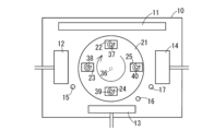
- FIG. 7 is a plan view showing a cathodic arc ion plating film forming apparatus used for forming a hard coating in this embodiment
- FIG. 8 is a front view.
- two types of films are formed on the substrate by arc ion plating using two cathode electrodes.
- the chamber 10 can be evacuated, and a reactive gas such as Ar gas or N 2 gas can be introduced into the chamber 10 .
- a reactive gas such as Ar gas or N 2 gas
- the chamber 10 can be filled with the reaction gas under a predetermined reduced pressure.
- a table 21 is supported by a rotating shaft 36 extending in the vertical direction.
- the table 21 is rotationally driven by an appropriate drive source (not shown) via a rotating shaft 36 .
- Rotation shafts 37 , 38 , 39 , 40 extending in the vertical direction are arranged on the table 21 at four equidistant positions on a circle centered on the rotation shaft 36 .
- the rotary shafts 37-40 are rotated by a planetary gear mounted on the rotary shaft 36 as a sun gear.
- a plurality of substrates 22, 23, 24, 25 are attached to each of the rotating shafts 37-40.
- the substrates 22 to 25 rotate around the rotation axes 37 to 40 and revolve around the rotation axis 36 .
- a heater 11, a first cathode electrode 12 as a first evaporation source, a third cathode electrode 13 as a bombardment cleaning source, and a second cathode electrode 14 as a second evaporation source are arranged around the table 21. They are arranged at substantially equal intervals counterclockwise in a plan view. The heater 11 heats the substrates 22-25.
- a first cathode electrode 12 for forming one of the two types of films formed on the substrates 22 to 25 and a second cathode electrode 14 for forming the other film are rotated. They are installed at positions facing each other with the shaft 36 interposed therebetween.
- a third cathode electrode 13 for bombardment cleaning is arranged between the first cathode electrode 12 and the second cathode electrode 14 .
- Metal Ti is usually used as the third cathode electrode 13 .
- Anode electrodes 15, 16 and 17 are arranged near the lower ends of the cathode electrodes 12, 13 and 14, respectively.
- a first arc power source 31 is connected between the first anode electrode 15 and the first cathode electrode 12 via a lead wire 34 .
- a second arc power source 32 is connected between the second anode electrode 17 and the second cathode electrode 14 via a lead wire 35 .
- An arc power source (not shown) is also connected between the third cathode electrode 13 and the third anode electrode 16 .
- a bias power supply 33 that applies a negative bias voltage to the substrates 22 to 25 is connected to the table 21 .
- the chamber 10 is provided with a process gas introduction port and an exhaust port for evacuation (both not shown).
- a TiAl target is placed on the first cathode electrode 12 as the first evaporation source, and an AlTiCrY target is placed on the second cathode electrode 14 as the second evaporation source.
- the TiAl target satisfies 0.4 ⁇ x ⁇ 0.70 (where x indicates an atomic ratio) when the composition is represented by Ti 1-x Al x .
- the AlTiCrY target has a composition of Al 1-yza Ti y Cr z Ya , where 0 ⁇ y ⁇ 0.45, 0 ⁇ z ⁇ 0.5, 0 ⁇ a ⁇ 0.02 (however, y, z, and a represent atomic ratios).
- the substrates 22-25 that have been dried after chemical cleaning are installed on the rotating shafts 37-40.
- the substrates 22 to 25 are, for example, SKD11 steel plates in the shape of a 25 mm ⁇ 25 mm square plate with a thickness of 7 mm.
- This base material is a quenched material with a hardness of 60 HRC.
- the chamber 10 is evacuated to a base pressure of, for example, 1 ⁇ 10 ⁇ 3 Pa, the table 21 is driven to rotate, and the rotating shafts 37 to 40 on the table 21 are driven to rotate. As a result, the substrates 22 to 25 held by the rotating shafts 37 to 40 are revolved by the table 21 and rotated on the table 21 . Then, the heater 11 is energized to heat the substrates 22 to 25 on the table 21 to a temperature of 450° C., for example. Since the substrates 22 to 25 are rotating and revolving, they are uniformly heated by the heater 11 .
- the lower layer 2 made of the (Ti,Al)N deposition film is formed on the substrates 22-25.
- the lower layer 2 is formed with a film thickness of 1.5 ⁇ m.
- a cathode current of, for example, 120 A is supplied to the second cathode electrode 14 while continuing to supply the cathode current to the first cathode electrode 12 and apply the bias voltage to the substrates 22 to 25 .
- two types of targets facing each other are simultaneously discharged, so that (Al, A first intermediate film 3a made of a Ti, Cr, Y)N film and a second intermediate film 3b made of a (Ti, Al)N film are alternately formed to form an intermediate layer 3 as a whole.
- the intermediate layer 3 is formed with a film thickness of 1.5 ⁇ m.
- the cathode current to the first cathode electrode 12 is set to 0 and the cathode current to the second cathode electrode 14 is set to 140 A, for example, while the application of the bias voltage to the substrates 22 to 25 is continued.
- the upper layer 4 made of the (Al, Ti, Cr, Y)N film is formed on the intermediate layer 3 .
- the upper layer 4 is formed with a film thickness of 1 ⁇ m.
- arc discharge is generated between the anode electrodes 15 and 16 by applying a negative voltage to the cathode electrodes 12 and 14 .
- This arc discharge forms an arc spot on the surface of the TiAl target placed on the first cathode electrode 12 or on the surface of the AlTiCrY target placed on the second cathode electrode 14, and randomly runs around the target surface. Then, the energy of the arc current concentrated on the arc spot instantly evaporates the target material, turns it into metal ions (positive ions), and flies out into the vacuum.
- the ejected metal ions are deposited on the surfaces of the substrates 22 to 25, which are objects to be coated (molds, cutting tools, machine parts, etc.) to form films.
- the metal ions (positive ions) in the vacuum fly toward the substrates 22 to 25 while being accelerated by an electric attractive force. , and collide with the surfaces of the substrates 22-25 with high energy together with reactive gas particles. As a result, the hard coating is formed in close contact with the surfaces of the substrates 22 to 25, producing a dense hard coating.
- the amount of metal ions ejected from the target and the amount of metal ions ejected from the substrates 22-25. can vary the speed at which it hits the surface of
- the thickness of the first intermediate film 3a and the second intermediate film 3b can be increased by making the magnitude of the arc current different between the first cathode electrode 12 and the second cathode electrode 14. can be different.
- the average composition of the two-layered film consisting of one layer of the first intermediate film 3a and one layer of the second intermediate film 3b adjacent to each other is adjusted to a desired composition between the composition of the TiAl target and the composition of the AlTiCrY target. can be designed to
- the intermediate layer 3 In the process of forming the intermediate layer 3, the magnitude of the arc current supplied to the cathode electrodes 12 and 14 and the substrate By changing the magnitude of the bias voltage applied to 22 to 25, the intermediate layer 3 can be formed in which the atomic ratio of Al, Ti, Cr and Y in the film thickness direction is changed.
- the intermediate layer 3 by stepwise or continuously increasing the magnitude of the arc current supplied to the first cathode electrode 12 holding the AlTiCrY target, the atomic ratio of Cr in the film thickness direction and Intermediate layer 3 having a composition in which each atomic ratio of Y increases toward upper layer 4 can be formed.
- the degree to which the magnitude of the arc current supplied to the first cathode electrode 12 is increased stepwise or continuously It may be made larger than when the film is formed on the side (lower layer 2 side).
- the rate of increase in the atomic ratio of Cr and the rate of increase in the atomic ratio of Y in the film thickness direction in the half of the intermediate layer 3 on the upper layer 4 side are higher than those in the half on the lower layer 2 side. growing.
- Example 2 A second embodiment will be described below with reference to the drawings. First, the structure of the hard coating of this embodiment will be described with reference to FIG. However, this embodiment is not limited to the tenth basic configuration.
- the lower layer 2 has a composition represented by (Ti 1-x Al x Mo b )N and is formed on the substrate 1 to a thickness of 1-8 ⁇ m.
- both x and b are atomic ratios, and 0.4 ⁇ x ⁇ 0.70 and 0 ⁇ b ⁇ 0.10.
- the upper layer 4 has a composition represented by (Al 1-yza Ti y Cr z Y a )N and a thickness of 1-8 ⁇ m.
- y, z, and a are atomic ratios, respectively, and 0 ⁇ y ⁇ 0.45, 0 ⁇ z ⁇ 0.5, and 0 ⁇ a ⁇ 0.02.
- the intermediate layer 3 is formed between the lower layer 2 and the upper layer 4 with a thickness of 1-5 ⁇ m.
- the intermediate layer 3 has a composition between that of the lower layer 2 and that of the upper layer 4 .
- the intermediate layer 3 is a film in which a film having the same composition as the lower layer 2 and a film having the same composition as the upper layer 4 are alternately laminated at a lamination cycle of 1 to 100 nm.
- Such a hard coating was formed in the same manner as the method of forming the hard coating of the first embodiment described above with reference to FIGS. 7 and 8.
- FIG. Here, an example in which a TiAlMo target is set as the first evaporation source on the first cathode electrode 12 and an AlTiCrY target is set as the second evaporation source on the second cathode electrode 14 will be described.
- the TiAlMo target has a composition of 0.4 ⁇ x ⁇ 0.70 and 0 ⁇ b ⁇ 0.10 (where x and b are both atomic ratio).
- the AlTiCrY target has a composition of Al 1-yza Ti y Cr z Ya , where 0 ⁇ y ⁇ 0.45, 0 ⁇ z ⁇ 0.5, 0 ⁇ a ⁇ 0.02 (however, y, z, and a represent atomic ratios).
- a hard coating of the second example was formed in the same manner as the method of forming the hard coating of the first example.
- a cathode current of 100 A for example, is supplied to the first cathode electrode 12 on which the TiAlMo target is placed, and a bias voltage of -50 V, for example, is applied to the substrates 22 to 25 by the bias power supply 33 .
- the lower layer 2 made of the (Ti, Al, Mo)N deposition film is formed on the substrates 22 to 25 to a thickness of 1.5 ⁇ m, for example.
- a cathode current of, for example, 120 A is supplied to the second cathode electrode 14, and as shown in FIG.
- First intermediate films 3a made of (Al,Ti,Cr,Y)N films and second intermediate films 3b made of (Ti,Al,Mo)N films are alternately formed on the lower layer 2.
- An intermediate layer 3 is formed as a whole.
- the intermediate layer 3 is formed with a film thickness of 1.5 ⁇ m.
- the cathode current to the first cathode electrode 12 is set to 0 and the cathode current to the second cathode electrode 14 is set to 140 A, for example, while the application of the bias voltage to the substrates 22 to 25 is continued.
- the upper layer 4 made of the (Al, Ti, Cr, Y)N film is formed on the intermediate layer 3 .
- the upper layer 4 is formed with a film thickness of 1 ⁇ m.
- the magnitude of the arc current supplied to the cathode electrodes 12 and 14 and the magnitude of the bias voltage applied to the substrates 22 to 25 are the same as in the formation method of the first embodiment.
- the thickness By changing the thickness, it is possible to change the amount of metal ions ejected from the target and the speed at which the metal ions collide with the surfaces of the substrates 22-25.
- the thickness of the first intermediate film 3a and the second intermediate film 3b can be increased by making the magnitude of the arc current different between the first cathode electrode 12 and the second cathode electrode 14. can be different.
- the average composition of the two-layered film consisting of one layer of the first intermediate film 3a and one layer of the second intermediate film 3b adjacent to each other is adjusted to a desired composition between the composition of the TiAlMo target and the composition of the AlTiCrY target. can be designed to
- the intermediate layer 3 In the process of forming the intermediate layer 3, the magnitude of the arc current supplied to the cathode electrodes 12 and 14 and the substrate By changing the magnitude of the bias voltage applied to 22 to 25, the intermediate layer 3 can be formed in which the atomic ratio of Al, Ti, Cr, Y and Mo in the film thickness direction is changed.
- the intermediate layer 3 by stepwise or continuously increasing the magnitude of the arc current supplied to the first cathode electrode 12 holding the AlTiCrY target, the atomic ratio of Cr in the film thickness direction and
- the intermediate layer 3 having a composition in which the Y atomic ratio increases toward the upper layer 4 side and the Mo atomic ratio in the film thickness direction decreases toward the upper layer 4 side can be formed.
- the conventional TiN coating and (Al,Ti)N coating exhibited a hardness of about 25 to 32 GPa at room temperature.
- conventional coatings were oxidized when heat treated at 900° C. and could not maintain their structure.
- the hard coatings of Examples 1 and 2 maintained the coating even after heat treatment at 900° C., the coating hardly peeled off, and the heat resistance was improved as compared with the conventional coating.
- the TiN coating and the (Ti,Al)N coating (conventional coating)
- a diamond indenter was struck from above the coating, and the adhesion was determined from the state of peeling of the coating. was evaluated (Rockwell hardness tester (ARK-F1000 (manufactured by Akashi), test load: 150 kg).
- Rockwell hardness tester ARK-F1000 (manufactured by Akashi), test load: 150 kg.
- the hard coatings of Examples 1 and 2 only cracks were observed around the indentations, and peeling of the coating was not observed. However, the adhesion was good (judgment result HF1 (VDI3198 standard)).
- the hard coatings of Examples 1 and 2 have better adhesion than the conventional coating.
- the coefficient of friction was measured for the hard coatings of Examples 1 and 2 and the (TiAl)N coating (conventional coating) (Tribogear TYPE: 14FW (manufactured by Shinto Kagaku Co., Ltd.), sliding speed: 600 m/min, Sliding length: 10 mm, load: 300 g, number of sliding: 100 times (reciprocating), mating material: SUJ2 ball (6 mm), measurement temperature: 700°C).
- the conventional film has a low friction coefficient of 0.23 to 0.37 at the beginning of measurement (1st time), abrasion powder is generated as the sliding is repeated, and the friction coefficient at the end of measurement (100th time) is 0.67 to 0.67. increased to 0.74.
- the hard coatings of Examples 1 and 2 had a coefficient of friction of 0.41 to 0.70 at the initial stage of measurement, which is higher than the conventional coating, but no abrasion powder was generated even after repeated sliding. .
- the coefficient of friction in the latter period of measurement of the first and second examples showed 0.61 to 0.67, which was not much higher than the coefficient of friction in the initial period of measurement (some samples were lower ).
- the hard coatings of the first and second embodiments have better wear resistance, low friction/high sliding properties, and adhesion resistance than conventional coatings.
- the hard coatings of the first and second embodiments have superior wear resistance, heat resistance, low friction/high sliding properties, and resistance to wear and heat as compared with conventional TiN coatings and (Ti,Al)N coatings. It showed weldability and adhesion.
- Example 1 the orientation of the obtained hard coating of Example 1 was evaluated by X-ray diffraction analysis.
- the X-ray output of the X-ray diffractometer is 9 kW (45 kV, 200 mA), the target used is Cu, and the measurement angle is 20-80°.
- the substrate is SKD11, 25 mm square and 7 mm thick.
- a hard film having a total film thickness of 8 ⁇ m was formed on this substrate and subjected to X-ray diffraction analysis.
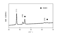
- Fig. 9 shows the results of X-ray diffraction analysis of the obtained hard coating.
- the vertical axis indicates the diffracted X-ray intensity (arbitrary unit), and the horizontal axis indicates the diffraction angle 2 ⁇ (degrees).
- peaks appear at (111), (200) and (220).
- the (111) orientation is determined by the formula I(111)/ ⁇ I(111)+I(200)+I(220) ⁇ .
- I(111), I(200) and I(220) are the peak intensities of (111), (200) and (220) respectively.
- the X-ray diffraction region is the entire thickness direction of the hard film.
- the (111) / ⁇ (111) + (200) + (220) ⁇ orientation (referred to as (111) orientation) is It was 50% or more in the entire film.
- the (111) oriented film has high film strength especially in the lateral direction (direction parallel to the surface) and exhibits durability when subjected to strong shear stress.
- the present invention is not limited to the above-described embodiments, and can be embodied in various aspects.
- the configuration of each part is not limited to the illustrated embodiment, and various modifications can be made without departing from the scope of the present invention.
- the respective configurations described in the above-described embodiments and modifications may be combined, and addition, omission, replacement, and other changes of configurations may be made. It is possible.
- the present invention is not limited to the embodiments described above.
Landscapes
- Chemical & Material Sciences (AREA)
- Engineering & Computer Science (AREA)
- Mechanical Engineering (AREA)
- Chemical Kinetics & Catalysis (AREA)
- Materials Engineering (AREA)
- Metallurgy (AREA)
- Organic Chemistry (AREA)
- Cutting Tools, Boring Holders, And Turrets (AREA)
- Physical Vapour Deposition (AREA)
Priority Applications (3)
| Application Number | Priority Date | Filing Date | Title |
|---|---|---|---|
| JP2023538955A JP7372002B1 (ja) | 2022-02-15 | 2022-12-22 | 硬質皮膜 |
| US18/837,568 US12486561B2 (en) | 2022-02-15 | 2022-12-22 | Hard coating |
| JP2023176691A JP2023178359A (ja) | 2022-02-15 | 2023-10-12 | 硬質皮膜 |
Applications Claiming Priority (2)
| Application Number | Priority Date | Filing Date | Title |
|---|---|---|---|
| JP2022-021468 | 2022-02-15 | ||
| JP2022021468 | 2022-02-15 |
Publications (1)
| Publication Number | Publication Date |
|---|---|
| WO2023157466A1 true WO2023157466A1 (ja) | 2023-08-24 |
Family
ID=87578052
Family Applications (1)
| Application Number | Title | Priority Date | Filing Date |
|---|---|---|---|
| PCT/JP2022/047417 Ceased WO2023157466A1 (ja) | 2022-02-15 | 2022-12-22 | 硬質皮膜 |
Country Status (3)
| Country | Link |
|---|---|
| US (1) | US12486561B2 (https=) |
| JP (2) | JP7372002B1 (https=) |
| WO (1) | WO2023157466A1 (https=) |
Cited By (1)
| Publication number | Priority date | Publication date | Assignee | Title |
|---|---|---|---|---|
| JPWO2024048672A1 (https=) * | 2022-08-31 | 2024-03-07 |
Families Citing this family (1)
| Publication number | Priority date | Publication date | Assignee | Title |
|---|---|---|---|---|
| JP7807856B1 (ja) * | 2025-09-30 | 2026-01-28 | Seavac株式会社 | 硬質皮膜 |
Citations (4)
| Publication number | Priority date | Publication date | Assignee | Title |
|---|---|---|---|---|
| JPH04337064A (ja) * | 1991-05-15 | 1992-11-25 | Mitsubishi Heavy Ind Ltd | 窒化硼素被覆部材 |
| JPH08165558A (ja) * | 1994-12-12 | 1996-06-25 | Toshiba Tungaloy Co Ltd | 窒化硼素被膜含有複合被覆体 |
| JP2012228735A (ja) * | 2011-04-25 | 2012-11-22 | Hitachi Tool Engineering Ltd | 耐摩耗性に優れる被覆工具およびその製造方法 |
| JP2021154415A (ja) * | 2020-03-26 | 2021-10-07 | 三菱マテリアル株式会社 | 耐欠損性にすぐれた表面被覆切削工具 |
Family Cites Families (19)
| Publication number | Priority date | Publication date | Assignee | Title |
|---|---|---|---|---|
| JPH02194159A (ja) | 1988-03-24 | 1990-07-31 | Kobe Steel Ltd | 耐摩耗性皮膜形成方法 |
| JP2840541B2 (ja) | 1994-05-13 | 1998-12-24 | 神鋼コベルコツール株式会社 | 耐摩耗性に優れた硬質皮膜、硬質皮膜被覆工具及び硬質皮膜被覆部材 |
| JP3836640B2 (ja) | 1998-10-27 | 2006-10-25 | 三菱マテリアル神戸ツールズ株式会社 | 耐摩耗性に優れた硬質皮膜および硬質皮膜被覆部材 |
| US6296928B1 (en) | 1998-10-27 | 2001-10-02 | Mmc Kobelco Tool Co., Ltd. | Hard coating coated member having excellent wear resistance |
| JP3248897B2 (ja) | 1999-03-19 | 2002-01-21 | 日立ツール株式会社 | 硬質皮膜被覆工具 |
| JP4112834B2 (ja) | 2000-12-28 | 2008-07-02 | 株式会社神戸製鋼所 | 切削工具用硬質皮膜を形成するためのターゲット |
| EP1992717B1 (en) | 2000-12-28 | 2012-02-15 | Kabushiki Kaisha Kobe Seiko Sho | Use of a target for arc ion plating to form a hard film |
| JP3640310B2 (ja) | 2002-11-25 | 2005-04-20 | 日立ツール株式会社 | 硬質皮膜 |
| DK1422311T3 (da) | 2002-11-19 | 2007-06-11 | Hitachi Tool Eng | Hård film og værktöj coatet med hård film |
| DE10347981A1 (de) | 2003-10-15 | 2005-07-07 | Gühring, Jörg, Dr. | Verschleißschutzschicht für spanabhebende Werkzeuge, insbesondere für rotierende Zerspanungswerkzeuge |
| WO2006006429A1 (ja) * | 2004-07-08 | 2006-01-19 | Sumitomo Electric Hardmetal Corp. | 圧縮応力の強度分布を有する被膜を備えた表面被覆切削工具 |
| JP3934136B2 (ja) * | 2004-11-11 | 2007-06-20 | 日立ツール株式会社 | 硬質皮膜被覆部材及びその被覆方法 |
| WO2006070509A1 (ja) * | 2004-12-28 | 2006-07-06 | Sumitomo Electric Hardmetal Corp. | 表面被覆切削工具および表面被覆切削工具の製造方法 |
| SE529838C2 (sv) * | 2005-12-08 | 2007-12-04 | Sandvik Intellectual Property | Belagt hårdmetallskär, sätt att framställa detta samt dess användning för fräsning i stål |
| JP4475230B2 (ja) | 2005-12-27 | 2010-06-09 | 三菱マテリアル株式会社 | 硬質皮膜 |
| JP5193153B2 (ja) | 2009-10-02 | 2013-05-08 | 株式会社神戸製鋼所 | 硬質皮膜、塑性加工用金型、塑性加工方法、及び硬質皮膜用ターゲット |
| JP5730535B2 (ja) | 2010-10-29 | 2015-06-10 | 株式会社神戸製鋼所 | 硬質皮膜形成部材および硬質皮膜の形成方法 |
| JP2016199793A (ja) * | 2015-04-13 | 2016-12-01 | 株式会社神戸製鋼所 | 硬質皮膜 |
| JP6347566B1 (ja) | 2017-10-13 | 2018-06-27 | 鋼鈑工業株式会社 | 硬質皮膜、この硬質皮膜が被覆された被覆材、表面処理方法及びアーク放電式イオンプレーティング用ターゲット材 |
-
2022
- 2022-12-22 WO PCT/JP2022/047417 patent/WO2023157466A1/ja not_active Ceased
- 2022-12-22 JP JP2023538955A patent/JP7372002B1/ja active Active
- 2022-12-22 US US18/837,568 patent/US12486561B2/en active Active
-
2023
- 2023-10-12 JP JP2023176691A patent/JP2023178359A/ja active Pending
Patent Citations (4)
| Publication number | Priority date | Publication date | Assignee | Title |
|---|---|---|---|---|
| JPH04337064A (ja) * | 1991-05-15 | 1992-11-25 | Mitsubishi Heavy Ind Ltd | 窒化硼素被覆部材 |
| JPH08165558A (ja) * | 1994-12-12 | 1996-06-25 | Toshiba Tungaloy Co Ltd | 窒化硼素被膜含有複合被覆体 |
| JP2012228735A (ja) * | 2011-04-25 | 2012-11-22 | Hitachi Tool Engineering Ltd | 耐摩耗性に優れる被覆工具およびその製造方法 |
| JP2021154415A (ja) * | 2020-03-26 | 2021-10-07 | 三菱マテリアル株式会社 | 耐欠損性にすぐれた表面被覆切削工具 |
Non-Patent Citations (1)
| Title |
|---|
| CHANG YIN-YU, CHUANG CHIH-CHENG: "Deposition of Multicomponent AlTiCrMoN Protective Coatings for Metal Cutting Applications", COATINGS, vol. 10, no. 7, pages 605, XP093086137, DOI: 10.3390/coatings10070605 * |
Cited By (2)
| Publication number | Priority date | Publication date | Assignee | Title |
|---|---|---|---|---|
| JPWO2024048672A1 (https=) * | 2022-08-31 | 2024-03-07 | ||
| JP7850815B2 (ja) | 2022-08-31 | 2026-04-23 | 京セラ株式会社 | 被覆工具および切削工具 |
Also Published As
| Publication number | Publication date |
|---|---|
| JP7372002B1 (ja) | 2023-10-31 |
| US12486561B2 (en) | 2025-12-02 |
| JPWO2023157466A1 (https=) | 2023-08-24 |
| JP2023178359A (ja) | 2023-12-14 |
| US20250215550A1 (en) | 2025-07-03 |
Similar Documents
| Publication | Publication Date | Title |
|---|---|---|
| CN1986487B (zh) | 带表面涂层的立方氮化硼基超高压烧结材料制切削工具 | |
| JP7372002B1 (ja) | 硬質皮膜 | |
| JP2008240079A (ja) | 被覆部材 | |
| JP5138892B2 (ja) | 硬質皮膜 | |
| JP5348223B2 (ja) | 被覆部材 | |
| KR102074469B1 (ko) | 포밍 치형공구용 다층나노 경질 코팅막 | |
| WO2020026392A1 (ja) | 硬質被膜および硬質被膜被覆部材 | |
| JP2023002267A (ja) | 硬質皮膜 | |
| JP2011045970A (ja) | 硬質被膜、および硬質被膜被覆工具 | |
| CN103339283B (zh) | 硬质层叠被膜 | |
| JP7807856B1 (ja) | 硬質皮膜 | |
| JP3543755B2 (ja) | 硬質被覆層がすぐれた切粉潤滑性を有する表面被覆高速度工具鋼製歯切工具 | |
| KR102747688B1 (ko) | 절삭공구용 경질피막 | |
| WO2020026390A1 (ja) | 硬質被膜および硬質被膜被覆部材 | |
| TWI720561B (zh) | 硬質被膜及硬質被膜被覆構件 | |
| KR101727420B1 (ko) | 내마모성이 우수한 적층 피막 | |
| CN103339284B (zh) | 硬质层叠被膜 | |
| JP4720987B2 (ja) | 高反応性被削材の高速歯切加工で硬質被覆層がすぐれた耐摩耗性を発揮する表面被覆高速度工具鋼製歯切工具 | |
| JP2011147946A (ja) | 温熱間鍛造用金型及びその製造方法 | |
| JP2008260097A (ja) | 表面被覆切削工具 | |
| KR102577510B1 (ko) | 수명이 향상된 키홈 제작 공구 | |
| JP4716095B2 (ja) | 合金鋼の高速歯切加工で硬質被覆層がすぐれた耐欠損性を発揮する表面被覆高速度工具鋼製歯切工具 | |
| JP2012233260A (ja) | 硬質皮膜 | |
| JP4706909B2 (ja) | 合金鋼の高速歯切加工で硬質被覆層がすぐれた耐摩耗性を発揮する表面被覆高速度工具鋼製歯切工具 | |
| JP4720986B2 (ja) | 合金鋼の高速歯切加工で硬質被覆層がすぐれた耐摩耗性を発揮する表面被覆高速度工具鋼製歯切工具 |
Legal Events
| Date | Code | Title | Description |
|---|---|---|---|
| WWE | Wipo information: entry into national phase |
Ref document number: 2023538955 Country of ref document: JP |
|
| 121 | Ep: the epo has been informed by wipo that ep was designated in this application |
Ref document number: 22927349 Country of ref document: EP Kind code of ref document: A1 |
|
| WWE | Wipo information: entry into national phase |
Ref document number: 2401001145 Country of ref document: TH |
|
| NENP | Non-entry into the national phase |
Ref country code: DE |
|
| 122 | Ep: pct application non-entry in european phase |
Ref document number: 22927349 Country of ref document: EP Kind code of ref document: A1 |
|
| WWP | Wipo information: published in national office |
Ref document number: 18837568 Country of ref document: US |