WO2023157183A1 - 電子機器 - Google Patents
電子機器 Download PDFInfo
- Publication number
- WO2023157183A1 WO2023157183A1 PCT/JP2022/006409 JP2022006409W WO2023157183A1 WO 2023157183 A1 WO2023157183 A1 WO 2023157183A1 JP 2022006409 W JP2022006409 W JP 2022006409W WO 2023157183 A1 WO2023157183 A1 WO 2023157183A1
- Authority
- WO
- WIPO (PCT)
- Prior art keywords
- fins
- electronic device
- base
- air guide
- extending
- Prior art date
- Legal status (The legal status is an assumption and is not a legal conclusion. Google has not performed a legal analysis and makes no representation as to the accuracy of the status listed.)
- Ceased
Links
Images






Classifications
-
- H—ELECTRICITY
- H05—ELECTRIC TECHNIQUES NOT OTHERWISE PROVIDED FOR
- H05K—PRINTED CIRCUITS; CASINGS OR CONSTRUCTIONAL DETAILS OF ELECTRIC APPARATUS; MANUFACTURE OF ASSEMBLAGES OF ELECTRICAL COMPONENTS
- H05K7/00—Constructional details common to different types of electric apparatus
- H05K7/20—Modifications to facilitate cooling, ventilating, or heating
- H05K7/20009—Modifications to facilitate cooling, ventilating, or heating using a gaseous coolant in electronic enclosures
- H05K7/20136—Forced ventilation, e.g. by fans
- H05K7/20145—Means for directing air flow, e.g. ducts, deflectors, plenum or guides
-
- B—PERFORMING OPERATIONS; TRANSPORTING
- B61—RAILWAYS
- B61C—LOCOMOTIVES; MOTOR RAILCARS
- B61C17/00—Arrangement or disposition of parts; Details or accessories not otherwise provided for; Use of control gear and control systems
-
- B—PERFORMING OPERATIONS; TRANSPORTING
- B61—RAILWAYS
- B61D—BODY DETAILS OR KINDS OF RAILWAY VEHICLES
- B61D27/00—Heating, cooling, ventilating, or air-conditioning
- B61D27/0072—Means for cooling only
-
- H—ELECTRICITY
- H05—ELECTRIC TECHNIQUES NOT OTHERWISE PROVIDED FOR
- H05K—PRINTED CIRCUITS; CASINGS OR CONSTRUCTIONAL DETAILS OF ELECTRIC APPARATUS; MANUFACTURE OF ASSEMBLAGES OF ELECTRICAL COMPONENTS
- H05K7/00—Constructional details common to different types of electric apparatus
- H05K7/20—Modifications to facilitate cooling, ventilating, or heating
- H05K7/20009—Modifications to facilitate cooling, ventilating, or heating using a gaseous coolant in electronic enclosures
- H05K7/20136—Forced ventilation, e.g. by fans
- H05K7/20154—Heat dissipaters coupled to components
- H05K7/20163—Heat dissipaters coupled to components the components being isolated from air flow, e.g. hollow heat sinks, wind tunnels or funnels
-
- H—ELECTRICITY
- H05—ELECTRIC TECHNIQUES NOT OTHERWISE PROVIDED FOR
- H05K—PRINTED CIRCUITS; CASINGS OR CONSTRUCTIONAL DETAILS OF ELECTRIC APPARATUS; MANUFACTURE OF ASSEMBLAGES OF ELECTRICAL COMPONENTS
- H05K7/00—Constructional details common to different types of electric apparatus
- H05K7/20—Modifications to facilitate cooling, ventilating, or heating
- H05K7/2039—Modifications to facilitate cooling, ventilating, or heating characterised by the heat transfer by conduction from the heat generating element to a dissipating body
- H05K7/20409—Outer radiating structures on heat dissipating housings, e.g. fins integrated with the housing
- H05K7/20418—Outer radiating structures on heat dissipating housings, e.g. fins integrated with the housing the radiating structures being additional and fastened onto the housing
-
- H—ELECTRICITY
- H05—ELECTRIC TECHNIQUES NOT OTHERWISE PROVIDED FOR
- H05K—PRINTED CIRCUITS; CASINGS OR CONSTRUCTIONAL DETAILS OF ELECTRIC APPARATUS; MANUFACTURE OF ASSEMBLAGES OF ELECTRICAL COMPONENTS
- H05K7/00—Constructional details common to different types of electric apparatus
- H05K7/20—Modifications to facilitate cooling, ventilating, or heating
- H05K7/2039—Modifications to facilitate cooling, ventilating, or heating characterised by the heat transfer by conduction from the heat generating element to a dissipating body
- H05K7/20509—Multiple-component heat spreaders; Multi-component heat-conducting support plates; Multi-component non-closed heat-conducting structures
-
- H—ELECTRICITY
- H05—ELECTRIC TECHNIQUES NOT OTHERWISE PROVIDED FOR
- H05K—PRINTED CIRCUITS; CASINGS OR CONSTRUCTIONAL DETAILS OF ELECTRIC APPARATUS; MANUFACTURE OF ASSEMBLAGES OF ELECTRICAL COMPONENTS
- H05K7/00—Constructional details common to different types of electric apparatus
- H05K7/20—Modifications to facilitate cooling, ventilating, or heating
- H05K7/20845—Modifications to facilitate cooling, ventilating, or heating for automotive electronic casings
- H05K7/20863—Forced ventilation, e.g. on heat dissipaters coupled to components
-
- H—ELECTRICITY
- H05—ELECTRIC TECHNIQUES NOT OTHERWISE PROVIDED FOR
- H05K—PRINTED CIRCUITS; CASINGS OR CONSTRUCTIONAL DETAILS OF ELECTRIC APPARATUS; MANUFACTURE OF ASSEMBLAGES OF ELECTRICAL COMPONENTS
- H05K7/00—Constructional details common to different types of electric apparatus
- H05K7/20—Modifications to facilitate cooling, ventilating, or heating
- H05K7/2089—Modifications to facilitate cooling, ventilating, or heating for power electronics, e.g. for inverters for controlling motor
- H05K7/20909—Forced ventilation, e.g. on heat dissipaters coupled to components
- H05K7/20918—Forced ventilation, e.g. on heat dissipaters coupled to components the components being isolated from air flow, e.g. hollow heat sinks, wind tunnels or funnels
Definitions
- This disclosure relates to electronic equipment.
- Some electronic devices have a cooling part that is thermally connected to the electronic parts that are heating elements, in order to prevent damage to the electronic parts due to heat generated when energized.
- An electronic device mounted on a railway vehicle which is an example of an electronic device, more specifically, a power converter, dissipates heat generated by electronic components into the running wind generated by the running of the vehicle via a cooling unit. to cool the electronic components.
- a cooling unit included in this type of electronic device Patent Document 1 discloses a heat sink attached to the underfloor of a railway vehicle.
- the heat sink disclosed in Patent Literature 1 has a base and a plurality of fins attached to the base and extending in the traveling direction and vertical direction of the vehicle.
- the heat sink disclosed in Patent Literature 1 includes a flat plate-like air regulating portion having a plurality of fins interposed between a main surface and a base at an end portion in the traveling direction of the vehicle, and an air regulating portion, in order to rectify the running wind. and a plate-shaped reinforcing part connected to the part and the base and covering the ends of the plurality of fins.
- the air regulating portion and the reinforcing portion By providing the air regulating portion and the reinforcing portion, the ends of the plurality of fins in the direction of travel are covered with a flat plate-shaped member whose main surface is along the direction of travel, so air flows into the fins from the ends in the direction of travel. The amount of air is reduced and the cooling performance is reduced.
- This problem is not limited to electronic devices mounted on a vehicle, but may occur in electronic devices having a structure that cools electronic components by transferring heat from fins to air supplied from the outside.
- the present disclosure has been made in view of the circumstances described above, and aims to provide an electronic device with high cooling performance.
- the electronic device of the present disclosure includes a heat conductive base, a plurality of fins, and one or a plurality of air guide members.
- An electronic component is attached to the first major surface of the base.
- the plurality of fins are attached to a second main surface opposite to the first main surface and are spaced apart from each other, and have a first extending direction along the second main surface and a direction away from the second main surface. Extending in both directions of the second extending direction, the heat transferred from the electronic component via the base is radiated to the air flowing around.
- the air guide member includes a first member extending around the plurality of fins and having a main surface intersecting the first extending direction, and attached to the first member and extending in a direction away from the center of the first extending direction of the fins. a second member having an extending major surface.
- the electronic device includes the air guide member having the first member and the second member, so that the ends of the plurality of fins are covered with a flat member having a main surface along the extending direction of the fins.
- the pressure difference between the windward side and the leeward side of the fins can be increased, and the flow velocity of the air flowing around the fins can be increased compared to the case where the fins are provided. As a result, an electronic device with high cooling performance can be obtained.
- FIG. 2 is a diagram showing an example of mounting an electronic device according to an embodiment on a vehicle;
- FIG. 2 is a cross-sectional view taken along line II-II in FIG. 1 of the electronic device according to the embodiment;
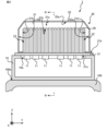
- Cross-sectional view taken along line III-III in FIG. 2 of the electronic device according to the embodiment 1 is a perspective view of an electronic device according to an embodiment;
- Front view of the air guide member according to the embodiment Perspective view of the air guide member according to the embodiment The figure which shows the flow of the air in the electronic device which is a comparative example.
- FIGS. 4A and 4B are diagrams showing air flows in the electronic device according to the embodiment; Sectional drawing of the 1st modification of the electronic device which concerns on embodiment Sectional view of the second modification of the electronic device according to the embodiment Sectional drawing of the third modification of the electronic device according to the embodiment Sectional view of the fourth modification of the electronic device according to the embodiment Sectional view of the fifth modification of the electronic device according to the embodiment
- An example of an electronic device is an in-vehicle device mounted on the roof of a railroad vehicle.
- An electronic device 1 according to an embodiment will be described by taking as an example an in-vehicle device that cools an electronic component by using running wind, which is an air flow generated by running of a railroad car and directed in a direction opposite to the traveling direction of the railroad car. .
- the electronic device 1 shown in FIG. 1 is installed on the roof 100a of a vehicle 100, which is, for example, a railroad vehicle.
- a vehicle 100 which is, for example, a railroad vehicle.
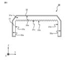
- FIG. 1 and FIG. 2 which is a cross-sectional view taken along line II-II in FIG. a plurality of fins 20 attached to the second main surface 21b of the base 21 and dissipating heat transferred from the electronic component 11 via the base 21 to the surrounding air; and a plurality of air guide members 30 .
- the electronic device 1 further includes a housing 10 installed on the roof 100 a and containing the electronic components 11 .
- the base 21 may be attached to the housing 10 while closing the opening 10a of the housing 10 .
- the Z axis indicates the vertical direction with the vehicle 100 positioned horizontally.
- the X-axis indicates the traveling direction of the vehicle 100 .
- the Y-axis indicates the width direction of vehicle 100 .
- the X-, Y-, and Z-axes are orthogonal to each other. The same applies to subsequent figures.
- the housing 10 is attached to the upper part of the roof 100a in the vertical direction.
- the housing 10 has such rigidity and strength that it does not deform even when subjected to the maximum expected vibration of the railway vehicle.
- the housing 10 is made of a metal member such as iron or aluminum.
- An opening 10a is formed in the upper portion of the housing 10 in the vertical direction.
- the base 21 is attached to the housing 10 while closing the opening 10a.
- the base 21 is a plate-shaped member made of a member having a high thermal conductivity, such as a metal member such as iron or aluminum, and is attached to the outer surface of the housing 10 while closing the opening 10a.
- a heat-generating electronic component 11 for example, a switching element included in a power conversion unit that converts power supplied from a power source into power for supplying a load device is attached.
- a plurality of fins 20 are attached to a second major surface 21b located opposite to the first major surface 21a. For example, the ends of the fins 20 are inserted into grooves formed in the second main surface 21b. With the vehicle 100 positioned horizontally, the first main surface 21a and the second main surface 21b are horizontal.
- the base 21 may be attached to the housing 10 with enough strength that the relative positional relationship between the base 21 and the housing 10 does not change even if the vehicle 100 is subjected to vibrations while the vehicle 100 is running.
- the base 21 is attached to the outer surface of the housing 10 by an attachment method such as fitting, brazing, welding, adhesion using an adhesive, or fastening using a fastening member.
- a plurality of fins 20 are attached to the second main surface 21b at intervals.
- twenty fins 20 are spaced apart from each other in the Y-axis direction and attached to the second major surface 21b.
- the plurality of fins 20 may be attached to the base 21 with such strength that the relative positional relationship between the base 21 and each fin 20 does not change even if the vehicle 100 is subjected to vibrations during travel.
- each fin 20 is attached to the second main surface 21b of the base 21 by an attachment method such as fitting, brazing, welding, adhesion using an adhesive, or fastening using a fastening member.
- Each fin 20 extends in both the first extension direction along the second main surface 21b and the second extension direction away from the second main surface 21b.
- the first draw direction is parallel to the X-axis and the second draw direction is parallel to the Z-axis.
- the fin 20 is formed of a flat member and attached to the second main surface 21b with the main surface perpendicular to the Y-axis.
- Each fin 20 dissipates heat transferred from the electronic component 11 through the base 21 to the surrounding air. For example, when the vehicle 100 is running, heat is transferred from the fins 20 to the running wind flowing along the fins 20 .
- Each fin 20 is made of a material with high thermal conductivity, such as a metal such as copper or aluminum.
- the electronic device 1 includes two air guide members 30 provided at both ends of the plurality of fins 20 in the X-axis direction.
- One of the two air guide members 30 extends around one end of each of the fins 20 in the first extending direction, for example, the end of each of the fins 20 on the X-axis positive direction side.
- one of the two air guide members 30 extends in the circumferential direction with respect to the X axis at a position adjacent to the end of each fin 20 on the positive side of the X axis.
- the other of the two air guide members 30 extends around the other end of each of the fins 20 in the first extending direction, for example, the end of each of the fins 20 on the X-axis negative direction side. Specifically, the other of the two air guide members 30 extends in the circumferential direction with respect to the X axis at a position adjacent to the end of each fin 20 on the negative side of the X axis.
- the two air guide members 30 have the same structure and are symmetrical with respect to the YZ plane including the center of the fin 20 in the X-axis direction.
- the wind guide member 30 may be provided at a position adjacent to the fins 20 to the extent that the running wind can be guided to the fins 20 .
- Each air guide member 30 should be attached to the base 21 with enough strength that the relative positional relationship between the base 21 and each air guide member 30 does not change even if the vehicle 100 is subjected to vibrations while the vehicle 100 is running.
- each air guide member 30 is attached to the second main surface 21b of the base 21 by an attachment method such as fitting, brazing, welding, adhesion using an adhesive, or fastening using a fastening member.
- Each air guide member 30 includes a first member 31 extending around the plurality of fins 20 and a second main surface attached to the first member 31 and extending away from the center of the fins 20 in the first extending direction. a member 32;
- the first member 31 is a plate-shaped member extending in the circumferential direction with respect to the X-axis. Specifically, the first member 31 has a main surface 31 a that intersects the first extending direction and side surfaces 31 b facing the plurality of fins 20 .
- the illustration of the housing 10 is omitted.
- the first member 31 contacts ends of the plurality of fins 20 far from the base 21 , in other words, ends of the plurality of fins 30 on the Z-axis positive direction side.
- the first member 31 is formed with a plurality of slits 31c each fitted with the end of the fin 20 on the Z-axis positive direction side. .
- the length in the Z-axis direction of the portion of the first member 31 located on the Z-axis positive side of the fins 20 is 1 ⁇ 5 or more and 1 ⁇ 3 or less of the length of the fins 20 in the Z-axis direction. is the length of Similarly, the length in the Y-axis direction of a portion of the first member 31 adjacent to the fin 20 in the Y-axis direction is 1 ⁇ 5 or more and 1 ⁇ 3 or less of the length of the fin 20 in the Z-axis direction. length.
- the distance between the second member 32 and the fins 20 is is equal to or less than 1/3 of the length of the fins 20 in the Z-axis direction, and the first member 31 and the second member 32 can guide the running wind to the ends of the fins 20 .
- the air guide member 30 is preferably made of a member having a coefficient of thermal expansion sufficiently close to that of the fins 20 to the extent that it can be prevented.
- the air guide member 30 is preferably made of the same material as the fins 20 .
- the first member 31 is a part of the fins 20 located at both ends in the arrangement direction of the plurality of fins 20, in other words, the positive Z-axis side of the fins 20 located at both ends in the Y-axis direction. is adjacent to a portion closer to the base 21 than the end of the base 21 with a gap 22 therebetween.
- the heat can be transferred from the fins 20 located at both ends in the Y-axis direction to the traveling wind passing through the gaps 22, and the cooling performance of the electronic device 1 is improved.
- the second member 32 is a plate-like member extending in the circumferential direction with respect to the X-axis and attached to the first member 31. As shown in FIG. The second member 32 only needs to be attached to the first member 31 with such strength that the relative positional relationship between the first member 31 and the second member 32 does not change even if the vehicle 100 is subjected to vibration during running. . Specifically, the second member 32 is attached to the main surface 31a of the first member 31 by an attachment method such as fitting, brazing, welding, adhesion using an adhesive, or fastening using a fastening member.
- the second member 32 has a main surface 32a extending away from the center of the fins 20 in the first extending direction, in other words, the center of the fins 20 in the X-axis direction.
- the main surface 32 a surrounds the plurality of fins 20 extending in the circumferential direction with respect to the X-axis.
- major surface 32a extends in the first stretching direction.
- the second member 32 is attached to the base 21.
- the second member 32 may be attached to the base 21 with such strength that the relative positional relationship between the second member 32 and the base 21 does not change even if the vehicle 100 is subjected to vibration during running.
- the second member 32 is attached to the second main surface 21b of the base 21 by an attachment method such as fitting, brazing, welding, adhesion using an adhesive, or fastening using a fastening member.
- the heat transferred from the electronic component 11 to the second member 32 via the base 21 is transferred from the second member 32 to the heat radiation from the second member 32 .
- Heat is dissipated by heat transfer to the surrounding air at 32 .
- the heat transferred from the electronic component 11 to the first member 31 via the base 21 and the second member 32 is transferred from the first member 31 to the heat radiation from the first member 31 and from the first member 31 to the air around the first member 31. heat is dissipated by the heat transfer of The electronic component 11 is cooled by heat radiation as described above.
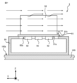
- FIG. 7 shows the flow of running air around an electronic device 9 that does not have the air guide member 30 .
- the flow of running air around the electronic device 9 is indicated by solid-line arrows.
- the configuration of the electronic device 9 is the same as that of the electronic device 1 except that the air guide member 30 is not provided.
- the electronic device 9 includes a housing 90 attached to the roof 100a of the vehicle 100, a base 91 mounted to the housing 90 in a direction to close the opening 90a of the housing 90, and a first main surface 91a of the base 91. and a plurality of fins 93 attached to the second major surface 91 b of the base 91 .
- the traveling wind that flows from the front to the rear in the traveling direction of the vehicle 100 in other words, the traveling wind that flows in the negative direction of the X axis flows along the fins 93 . While flowing between the fins 93 , part of the running wind moves in the Z-axis positive direction and flows along the ends of the fins 93 on the Z-axis positive direction side.
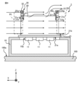
- FIG. 8 shows the flow of wind around the electronic device 1 .
- the flow of running air around the electronic device 1 is indicated by solid arrows. Since the electronic device 1 includes the wind guide member 30 surrounding the ends of the fins 20 on the positive side of the X axis, part of the running wind flowing in the negative direction of the X axis is guided by the wind guide member 30 and After flowing in the direction, it reaches the end of the fin 20 on the positive side of the X axis. In other words, more running wind than in the case of FIG. 7 reaches the ends of the fins 20 on the positive side of the X axis. As a result, the air pressure in the region R1 indicated by the dashed line in FIG. 8, specifically, the region R1 including the ends of the fins 20 on the positive side of the X axis, becomes higher than in FIG. Higher positive pressure.
- the electronic device 1 While flowing between the fins 20 , part of the running wind moves in the Z-axis positive direction and flows along the ends of the fins 20 on the Z-axis positive direction side. Since the electronic device 1 includes the wind guide member 30 surrounding the ends of the fins 20 on the negative side of the X-axis, the running wind flowing along the ends of the fins 20 on the positive side of the Z-axis moves further in the positive Z-axis direction. Then, the air bypasses the wind guide member 30 and flows in the negative direction of the X axis. As a result, as indicated by the dashed line in FIG. 8, the air pressure in the region R2 including the ends of the fins 20 on the negative side of the X axis becomes lower than in the case of FIG. Become.
- the pressure difference between the end of the fin 20 on the positive side of the X-axis and the end of the fin 20 on the negative side of the X-axis becomes larger than in the case of FIG.
- the speed of the running wind flowing between the fins 20 in the negative direction of the X-axis increases, so the cooling performance of the electronic device 1 improves.
- the air pressure in the region R2 becomes positive pressure and the air pressure in the region R1 becomes negative pressure, so that the wind guide member 30 is not provided as shown in FIG.
- the speed of the running wind flowing between the fins 20 in the positive direction of the X-axis is faster, so the cooling performance of the electronic device 1 is improved.
- the size of the air guide member 30 specifically, the area of the main surface 31a of the first member 31 increases, the air pressure in the region R1 increases and the air pressure in the region R2 decreases.
- the cooling performance of the electronic device 1 is improved.
- the size of the air guide member 30 is determined according to the cooling performance required for the electronic device 1 and the vehicle limit range.
- the pressure at the ends of the fins 20 on the positive side of the X-axis and the ends of the fins 20 on the negative side of the X-axis is reduced. the difference increases. As a result, the speed of the running wind flowing between the fins 20 increases, so the cooling performance of the electronic device 1 improves.
- the base 21 can be attached to the upper portion of the housing 10 in the vertical direction using the air guide member 30 as a handle when assembling the electronic device 1 . Since the air guide member 30 is attached to the base 21, even when the air guide member 30 is used as a handle, no stress is generated in the fins 20, and deformation of the fins 20 during assembly of the electronic device 1 is suppressed. becomes possible.
- the present disclosure is not limited to the above embodiments.
- the shape of the air guide member 30 is arbitrary as long as it can increase the pressure difference between the ends of the fins 20 on the positive side of the X-axis and the ends of the fins 20 on the negative side of the X-axis.
- FIG. 9 shows an example of an electronic device 2 having a wind guide member 30 having a shape different from that of the embodiment.
- the air guide member 30 included in the electronic device 2 has a first member 31 and a second member 33 attached to the first member 31 .
- the second member 33 has a main surface 33a that extends away from the center of the fins 20 in the X-axis direction and surrounds the plurality of fins 20 .
- the area of the cross section perpendicular to the first extending direction of the space surrounded by the second member 33 and the base 21 becomes narrower toward the center of the fin 20 in the first extending direction.
- the length of one end near the center of the fin 20 in the first stretching direction around the X axis is shorter than the length around the X-axis of the end.
- the number of air guide members 30 provided in the electronic devices 1 and 2 is arbitrary.
- the electronic devices 1 and 2 may include only the air guide member 30 positioned on the X-axis positive direction side, or only the air guide member 30 positioned on the X-axis negative direction side.
- FIG. 10 shows an electronic device 3 having four air guide members 30 .
- the four air guide members 30 included in the electronic device 3 have the same structure, and are symmetrical with respect to the YZ plane including the center of the fins 20 in the X-axis direction.
- FIG. 11 shows an electronic device 4 having a wind guide member 30 attached to the housing 10 .
- the second member 32 of the air guide member 30 included in the electronic device 4 has a strength that does not change the relative positional relationship between the second member 32 and the housing 10 even when subjected to vibrations during running of the vehicle 100 . It may be attached to the housing 10 .
- the second member 32 is attached to the outer surface of the housing 10 by an attachment method such as fitting, brazing, welding, adhesion using an adhesive, or fastening using a fastening member.
- the first member 31 of the air guide member 30 is in contact with the plurality of fins 20, but the first member 31 may be separated from the plurality of fins 20 as shown in FIG.
- the first member is such that the air pressure at the end of the fins 20 in the X-axis direction can be positive pressure or the air pressure at the end of the fins 20 in the X-axis direction can be negative pressure.
- 31 is preferably provided at a position sufficiently close to the plurality of fins 20 .
- the shapes of the first member 31 and the second members 32, 33 are not limited to the above examples.
- a portion of the first member 31 may have a shape that contacts the base 21 or the housing 10 .
- the first member 31 may be attached to the base 21 or the housing 10 .
- the first member 31 and the second member 32 or 33 may be integrally formed.
- FIG. 13 shows an electronic device 6 having fins arranged side by side in the X-axis direction and the Y-axis direction.
- the electronic device 6 includes 20 fins 20a arranged in the Y-axis direction, and 20 fins 20b arranged in the Y-axis direction and located on the negative X-axis side of the fins 20a.
- the electronic device 6 includes two air guide members 30a provided at both ends of the plurality of fins 20a in the X-axis direction, and two air guide members 30b provided at both ends of the plurality of fins 20b in the X-axis direction.
- the structure of each of the air guide members 30 a and 30 b is the same as that of the air guide member 30 .
- the two air guide members 30a are provided in directions symmetrical with respect to the YZ plane including the center of the fins 20a in the X-axis direction.
- the two air guide members 30b are provided in directions symmetrical with respect to the YZ plane including the center of the fins 20b in the X-axis direction.
- the shape of the fins 20, 20a, 20b is not limited to the above example, and may be, for example, a plate-like member with uneven thickness, a member having a curved surface, or the like.
- the electronic component 11 is not limited to a switching element, and may be any electronic component such as a thyristor, a diode, or the like that is housed inside the housing 10 and generates heat.
- the method by which the electronic device 1-6 cools the electronic component 11 is not limited to cooling using running wind.
- the electronic device 1-6 may cool the electronic component 11 by transferring heat to cooling air supplied from a blower and flowing between the fins 20, 20a, 20b.
- the mounting location of the electronic device 1-6 is not limited to the roof 100a of the vehicle 100.
- electronic device 1 - 6 may be provided under the floor of vehicle 100 .
- the electronic device 1-6 is not limited to railroad vehicles, and can be attached to any moving body such as a trolleybus or a streetcar that generates running wind.
- the electronic devices 1-6 are not limited to in-vehicle devices mounted on railway vehicles, and may be arbitrary electronic devices installed indoors or outdoors. In this case, the electronic device 1-6 may cool the electronic component 11 by transferring heat to the cooling air supplied from the blower and flowing between the fins 20, 20a, and 20b.
Landscapes
- Engineering & Computer Science (AREA)
- Microelectronics & Electronic Packaging (AREA)
- Physics & Mathematics (AREA)
- Thermal Sciences (AREA)
- Mechanical Engineering (AREA)
- Automation & Control Theory (AREA)
- Transportation (AREA)
- Cooling Or The Like Of Electrical Apparatus (AREA)
- Cooling Or The Like Of Semiconductors Or Solid State Devices (AREA)
Priority Applications (6)
| Application Number | Priority Date | Filing Date | Title |
|---|---|---|---|
| US18/718,074 US20250048584A1 (en) | 2022-02-17 | 2022-02-17 | Electronic device |
| CN202290000874.5U CN221930483U (zh) | 2022-02-17 | 2022-02-17 | 电子设备 |
| DE112022006667.9T DE112022006667T5 (de) | 2022-02-17 | 2022-02-17 | Electronische einrichtung |
| EP22927085.5A EP4482268A4 (en) | 2022-02-17 | 2022-02-17 | Electronic device |
| PCT/JP2022/006409 WO2023157183A1 (ja) | 2022-02-17 | 2022-02-17 | 電子機器 |
| JP2024500818A JP7531745B2 (ja) | 2022-02-17 | 2022-02-17 | 電子機器 |
Applications Claiming Priority (1)
| Application Number | Priority Date | Filing Date | Title |
|---|---|---|---|
| PCT/JP2022/006409 WO2023157183A1 (ja) | 2022-02-17 | 2022-02-17 | 電子機器 |
Publications (1)
| Publication Number | Publication Date |
|---|---|
| WO2023157183A1 true WO2023157183A1 (ja) | 2023-08-24 |
Family
ID=87577854
Family Applications (1)
| Application Number | Title | Priority Date | Filing Date |
|---|---|---|---|
| PCT/JP2022/006409 Ceased WO2023157183A1 (ja) | 2022-02-17 | 2022-02-17 | 電子機器 |
Country Status (6)
| Country | Link |
|---|---|
| US (1) | US20250048584A1 (https=) |
| EP (1) | EP4482268A4 (https=) |
| JP (1) | JP7531745B2 (https=) |
| CN (1) | CN221930483U (https=) |
| DE (1) | DE112022006667T5 (https=) |
| WO (1) | WO2023157183A1 (https=) |
Cited By (2)
| Publication number | Priority date | Publication date | Assignee | Title |
|---|---|---|---|---|
| CN118234209A (zh) * | 2024-05-27 | 2024-06-21 | 成都纵横智控科技有限公司 | 一种分布式边缘终端设备 |
| WO2025220059A1 (ja) * | 2024-04-15 | 2025-10-23 | 三菱電機株式会社 | 冷却装置および電子機器 |
Citations (7)
| Publication number | Priority date | Publication date | Assignee | Title |
|---|---|---|---|---|
| JPH05259325A (ja) * | 1992-03-10 | 1993-10-08 | Nec Corp | 半導体装置 |
| JPH0623256U (ja) * | 1992-08-26 | 1994-03-25 | 本田技研工業株式会社 | ヒートシンクのフィン構造 |
| JPH06315265A (ja) * | 1993-04-27 | 1994-11-08 | Toshiba F Ee Syst Eng Kk | 電力変換装置の冷却構造 |
| JP2001168561A (ja) * | 1999-12-07 | 2001-06-22 | Mitsubishi Alum Co Ltd | 放熱器 |
| WO2010109799A1 (ja) | 2009-03-24 | 2010-09-30 | 住友精密工業株式会社 | ヒートシンク |
| JP2017039481A (ja) * | 2015-08-21 | 2017-02-23 | 株式会社東芝 | 電力変換装置及び鉄道車両 |
| JP2018100069A (ja) * | 2016-05-31 | 2018-06-28 | 富士電機株式会社 | 鉄道車両用電力変換装置 |
Family Cites Families (7)
| Publication number | Priority date | Publication date | Assignee | Title |
|---|---|---|---|---|
| JP4149100B2 (ja) * | 1999-10-01 | 2008-09-10 | 水谷電機工業株式会社 | 電子部品の放熱器 |
| JP4322910B2 (ja) * | 2006-10-20 | 2009-09-02 | 株式会社東芝 | 鉄道車両用電力変換装置 |
| US10015913B2 (en) * | 2016-02-15 | 2018-07-03 | Fuji Electric Co., Ltd. | Power converter and cooler |
| JP6048607B1 (ja) * | 2016-04-15 | 2016-12-21 | 富士電機株式会社 | 鉄道車両用電力変換装置 |
| JP6652467B2 (ja) * | 2016-08-31 | 2020-02-26 | 株式会社日立製作所 | 電力変換装置および電力変換装置を搭載した鉄道車両 |
| JP6888468B2 (ja) * | 2017-08-01 | 2021-06-16 | 富士電機株式会社 | 鉄道車両用電力変換装置 |
| KR102671866B1 (ko) * | 2019-01-17 | 2024-05-31 | 엘에스일렉트릭(주) | 인버터용 방열모듈 |
-
2022
- 2022-02-17 WO PCT/JP2022/006409 patent/WO2023157183A1/ja not_active Ceased
- 2022-02-17 DE DE112022006667.9T patent/DE112022006667T5/de active Pending
- 2022-02-17 US US18/718,074 patent/US20250048584A1/en active Pending
- 2022-02-17 JP JP2024500818A patent/JP7531745B2/ja active Active
- 2022-02-17 EP EP22927085.5A patent/EP4482268A4/en active Pending
- 2022-02-17 CN CN202290000874.5U patent/CN221930483U/zh active Active
Patent Citations (7)
| Publication number | Priority date | Publication date | Assignee | Title |
|---|---|---|---|---|
| JPH05259325A (ja) * | 1992-03-10 | 1993-10-08 | Nec Corp | 半導体装置 |
| JPH0623256U (ja) * | 1992-08-26 | 1994-03-25 | 本田技研工業株式会社 | ヒートシンクのフィン構造 |
| JPH06315265A (ja) * | 1993-04-27 | 1994-11-08 | Toshiba F Ee Syst Eng Kk | 電力変換装置の冷却構造 |
| JP2001168561A (ja) * | 1999-12-07 | 2001-06-22 | Mitsubishi Alum Co Ltd | 放熱器 |
| WO2010109799A1 (ja) | 2009-03-24 | 2010-09-30 | 住友精密工業株式会社 | ヒートシンク |
| JP2017039481A (ja) * | 2015-08-21 | 2017-02-23 | 株式会社東芝 | 電力変換装置及び鉄道車両 |
| JP2018100069A (ja) * | 2016-05-31 | 2018-06-28 | 富士電機株式会社 | 鉄道車両用電力変換装置 |
Non-Patent Citations (1)
| Title |
|---|
| See also references of EP4482268A4 |
Cited By (2)
| Publication number | Priority date | Publication date | Assignee | Title |
|---|---|---|---|---|
| WO2025220059A1 (ja) * | 2024-04-15 | 2025-10-23 | 三菱電機株式会社 | 冷却装置および電子機器 |
| CN118234209A (zh) * | 2024-05-27 | 2024-06-21 | 成都纵横智控科技有限公司 | 一种分布式边缘终端设备 |
Also Published As
| Publication number | Publication date |
|---|---|
| CN221930483U (zh) | 2024-10-29 |
| EP4482268A4 (en) | 2025-04-09 |
| DE112022006667T5 (de) | 2024-11-28 |
| EP4482268A1 (en) | 2024-12-25 |
| JPWO2023157183A1 (https=) | 2023-08-24 |
| JP7531745B2 (ja) | 2024-08-09 |
| US20250048584A1 (en) | 2025-02-06 |
Similar Documents
| Publication | Publication Date | Title |
|---|---|---|
| US8813832B2 (en) | Heat sink | |
| JP7531745B2 (ja) | 電子機器 | |
| JP2000092819A (ja) | 半導体冷却装置 | |
| KR101588989B1 (ko) | 차량용 언더 플로어 장치의 냉각 장치 | |
| CN101516713A (zh) | 移动体用冷却装置 | |
| WO2021199252A1 (ja) | 電力変換装置 | |
| JP4322910B2 (ja) | 鉄道車両用電力変換装置 | |
| JP5930911B2 (ja) | 電力変換装置 | |
| JP6222938B2 (ja) | 放熱装置 | |
| JP2001260877A (ja) | 鉄道車両用電力変換装置 | |
| JP2005053330A (ja) | 鉄道車両用電力変換装置 | |
| JP7408017B2 (ja) | 電子機器 | |
| US12588170B2 (en) | In-vehicle device including cooling apparatus | |
| JP6837565B2 (ja) | 鉄道車両の電力変換装置および電力変換装置を搭載した鉄道車両 | |
| JP7446528B2 (ja) | 車載機器 | |
| JP3887352B2 (ja) | 鉄道車両用電力変換装置 | |
| JP4322898B2 (ja) | 鉄道車両用電力変換装置 | |
| JP4011272B2 (ja) | 半導体冷却装置 | |
| JP7738811B2 (ja) | コイル装置および車載機器 | |
| JP3879080B2 (ja) | 車両用発熱電気品の冷却装置 | |
| WO2025220059A1 (ja) | 冷却装置および電子機器 | |
| WO2025046663A1 (ja) | 電子機器 | |
| US20240053114A1 (en) | Heat dissipation structure for a casting block assembly | |
| JP2022085986A (ja) | 鉄道車両用の冷却装置 | |
| JP2004087553A (ja) | 車両用電力変換装置 |
Legal Events
| Date | Code | Title | Description |
|---|---|---|---|
| 121 | Ep: the epo has been informed by wipo that ep was designated in this application |
Ref document number: 22927085 Country of ref document: EP Kind code of ref document: A1 |
|
| WWE | Wipo information: entry into national phase |
Ref document number: 2024500818 Country of ref document: JP |
|
| WWE | Wipo information: entry into national phase |
Ref document number: 18718074 Country of ref document: US |
|
| WWE | Wipo information: entry into national phase |
Ref document number: 202290000874.5 Country of ref document: CN |
|
| WWE | Wipo information: entry into national phase |
Ref document number: 202427060112 Country of ref document: IN |
|
| WWE | Wipo information: entry into national phase |
Ref document number: 112022006667 Country of ref document: DE Ref document number: 2022927085 Country of ref document: EP |
|
| ENP | Entry into the national phase |
Ref document number: 2022927085 Country of ref document: EP Effective date: 20240917 |