WO2021199252A1 - 電力変換装置 - Google Patents
電力変換装置 Download PDFInfo
- Publication number
- WO2021199252A1 WO2021199252A1 PCT/JP2020/014762 JP2020014762W WO2021199252A1 WO 2021199252 A1 WO2021199252 A1 WO 2021199252A1 JP 2020014762 W JP2020014762 W JP 2020014762W WO 2021199252 A1 WO2021199252 A1 WO 2021199252A1
- Authority
- WO
- WIPO (PCT)
- Prior art keywords
- power conversion
- vehicle
- conversion device
- housing
- heat
- Prior art date
Links
Images


Classifications
-
- H—ELECTRICITY
- H02—GENERATION; CONVERSION OR DISTRIBUTION OF ELECTRIC POWER
- H02M—APPARATUS FOR CONVERSION BETWEEN AC AND AC, BETWEEN AC AND DC, OR BETWEEN DC AND DC, AND FOR USE WITH MAINS OR SIMILAR POWER SUPPLY SYSTEMS; CONVERSION OF DC OR AC INPUT POWER INTO SURGE OUTPUT POWER; CONTROL OR REGULATION THEREOF
- H02M7/00—Conversion of ac power input into dc power output; Conversion of dc power input into ac power output
- H02M7/003—Constructional details, e.g. physical layout, assembly, wiring or busbar connections
-
- H—ELECTRICITY
- H02—GENERATION; CONVERSION OR DISTRIBUTION OF ELECTRIC POWER
- H02M—APPARATUS FOR CONVERSION BETWEEN AC AND AC, BETWEEN AC AND DC, OR BETWEEN DC AND DC, AND FOR USE WITH MAINS OR SIMILAR POWER SUPPLY SYSTEMS; CONVERSION OF DC OR AC INPUT POWER INTO SURGE OUTPUT POWER; CONTROL OR REGULATION THEREOF
- H02M7/00—Conversion of ac power input into dc power output; Conversion of dc power input into ac power output
- H02M7/42—Conversion of dc power input into ac power output without possibility of reversal
- H02M7/44—Conversion of dc power input into ac power output without possibility of reversal by static converters
- H02M7/48—Conversion of dc power input into ac power output without possibility of reversal by static converters using discharge tubes with control electrode or semiconductor devices with control electrode
- H02M7/53—Conversion of dc power input into ac power output without possibility of reversal by static converters using discharge tubes with control electrode or semiconductor devices with control electrode using devices of a triode or transistor type requiring continuous application of a control signal
- H02M7/537—Conversion of dc power input into ac power output without possibility of reversal by static converters using discharge tubes with control electrode or semiconductor devices with control electrode using devices of a triode or transistor type requiring continuous application of a control signal using semiconductor devices only, e.g. single switched pulse inverters
- H02M7/5387—Conversion of dc power input into ac power output without possibility of reversal by static converters using discharge tubes with control electrode or semiconductor devices with control electrode using devices of a triode or transistor type requiring continuous application of a control signal using semiconductor devices only, e.g. single switched pulse inverters in a bridge configuration
-
- H—ELECTRICITY
- H05—ELECTRIC TECHNIQUES NOT OTHERWISE PROVIDED FOR
- H05K—PRINTED CIRCUITS; CASINGS OR CONSTRUCTIONAL DETAILS OF ELECTRIC APPARATUS; MANUFACTURE OF ASSEMBLAGES OF ELECTRICAL COMPONENTS
- H05K7/00—Constructional details common to different types of electric apparatus
- H05K7/14—Mounting supporting structure in casing or on frame or rack
- H05K7/1422—Printed circuit boards receptacles, e.g. stacked structures, electronic circuit modules or box like frames
- H05K7/1427—Housings
- H05K7/1432—Housings specially adapted for power drive units or power converters
-
- H—ELECTRICITY
- H05—ELECTRIC TECHNIQUES NOT OTHERWISE PROVIDED FOR
- H05K—PRINTED CIRCUITS; CASINGS OR CONSTRUCTIONAL DETAILS OF ELECTRIC APPARATUS; MANUFACTURE OF ASSEMBLAGES OF ELECTRICAL COMPONENTS
- H05K7/00—Constructional details common to different types of electric apparatus
- H05K7/20—Modifications to facilitate cooling, ventilating, or heating
- H05K7/2029—Modifications to facilitate cooling, ventilating, or heating using a liquid coolant with phase change in electronic enclosures
- H05K7/20336—Heat pipes, e.g. wicks or capillary pumps
-
- H—ELECTRICITY
- H05—ELECTRIC TECHNIQUES NOT OTHERWISE PROVIDED FOR
- H05K—PRINTED CIRCUITS; CASINGS OR CONSTRUCTIONAL DETAILS OF ELECTRIC APPARATUS; MANUFACTURE OF ASSEMBLAGES OF ELECTRICAL COMPONENTS
- H05K7/00—Constructional details common to different types of electric apparatus
- H05K7/20—Modifications to facilitate cooling, ventilating, or heating
- H05K7/2089—Modifications to facilitate cooling, ventilating, or heating for power electronics, e.g. for inverters for controlling motor
- H05K7/209—Heat transfer by conduction from internal heat source to heat radiating structure
-
- H—ELECTRICITY
- H05—ELECTRIC TECHNIQUES NOT OTHERWISE PROVIDED FOR
- H05K—PRINTED CIRCUITS; CASINGS OR CONSTRUCTIONAL DETAILS OF ELECTRIC APPARATUS; MANUFACTURE OF ASSEMBLAGES OF ELECTRICAL COMPONENTS
- H05K7/00—Constructional details common to different types of electric apparatus
- H05K7/20—Modifications to facilitate cooling, ventilating, or heating
- H05K7/2089—Modifications to facilitate cooling, ventilating, or heating for power electronics, e.g. for inverters for controlling motor
- H05K7/20936—Liquid coolant with phase change
-
- H—ELECTRICITY
- H02—GENERATION; CONVERSION OR DISTRIBUTION OF ELECTRIC POWER
- H02P—CONTROL OR REGULATION OF ELECTRIC MOTORS, ELECTRIC GENERATORS OR DYNAMO-ELECTRIC CONVERTERS; CONTROLLING TRANSFORMERS, REACTORS OR CHOKE COILS
- H02P27/00—Arrangements or methods for the control of AC motors characterised by the kind of supply voltage
- H02P27/04—Arrangements or methods for the control of AC motors characterised by the kind of supply voltage using variable-frequency supply voltage, e.g. inverter or converter supply voltage
- H02P27/06—Arrangements or methods for the control of AC motors characterised by the kind of supply voltage using variable-frequency supply voltage, e.g. inverter or converter supply voltage using dc to ac converters or inverters
Definitions
- This disclosure relates to a power conversion device.
- Some power converters mounted on vehicles have a cooling device that is thermally connected to the electronic components that are heating elements in order to prevent damage to the electronic components due to heat generated during energization.
- the cooling device cools the electronic components by dissipating the heat transferred from the electronic components to the traveling wind generated by the traveling of the vehicle.
- An example of this type of power conversion device is disclosed in Patent Document 1.
- the power conversion device disclosed in Patent Document 1 has a cooling device mounted under the floor of a railroad vehicle and mounted on a side surface intersecting in the direction of sleepers.
- the present disclosure has been made in view of the above circumstances, and an object of the present disclosure is to provide a power conversion device having high cooling efficiency.
- the power conversion device of the present disclosure includes a power conversion unit, a housing, a heat receiving block, and at least one heat pipe.
- the power conversion unit converts the supplied electric power into electric power for supplying the load, and supplies the converted electric power to the load.
- the housing houses the electronic components of the power converter and has an opening at the top in the vertical direction.
- the housing is installed on the roof of the vehicle.
- Electronic components are attached to one main surface of the heat receiving block.
- the heat receiving block is attached to the housing and closes the opening.
- At least one heat pipe is attached to the other main surface of the heat receiving block, extends in a direction away from the heat receiving block, and is filled with a refrigerant.
- the heat pipe of the power conversion device according to the present disclosure is provided on the roof of the vehicle, it is possible to efficiently transfer the heat generated by the electronic components to the running wind. As a result, it is possible to improve the cooling performance of the power conversion device.
- FIG. 6 is a cross-sectional view taken along the line BB of the power conversion device according to the second embodiment.
- FIG. 8 is a cross-sectional view taken along the line CC of FIG. 8 of the wind guide member according to the third embodiment.
- FIG. 11 is a cross-sectional view taken along the line DD of FIG. 11 of a second modification of the power conversion device according to the embodiment.
- the power conversion device according to the first embodiment will be described by taking as an example a self-cooling power conversion device mounted on the roof of a railroad vehicle and cooling electronic components by using running wind.
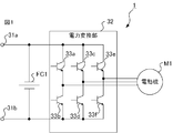
- the power conversion device 1 shown in FIG. 1 converts DC power supplied from a power source (not shown) into three-phase AC power for supplying to the motor M1 which is a load, and supplies the three-phase AC power to the motor M1.
- the power supply is, for example, a current collector that acquires electric power from an overhead wire.
- the electric motor M1 is, for example, a three-phase induction motor.
- the power conversion device 1 is composed of a primary terminal 31a connected to a power supply, a grounded primary terminal 31b, a filter capacitor FC1 having both ends connected to the primary terminals 31a and 31b to remove ripples, and a power supply. It includes a power conversion unit 32 that converts the supplied DC power into three-phase AC power and supplies it to the electric motor M1.
- the power conversion unit 32 includes switching elements 33a and 33b corresponding to the U phase, switching elements 33c and 33d corresponding to the V phase, and switching elements 33e and 33f corresponding to the W phase.
- a switching control unit (not shown) switches the switching elements 33a-33f on and off, so that the power conversion unit 32 converts the DC power supplied from the power source into three-phase AC power and supplies it to the motor M1.
- the power conversion device 1 is provided on the roof 100a of the vehicle 100 as shown in FIG. Specifically, the power conversion device 1 is attached to the upper end of the roof 100a in the vertical direction with the vehicle 100 positioned horizontally.
- the X-axis indicates the traveling direction of the vehicle 100. In other words, the vehicle 100 travels in the positive X-axis direction or the negative X-axis direction.
- the Y-axis indicates the width direction of the vehicle 100, in other words, the sleeper direction.
- the Z-axis is orthogonal to each of the X-axis and the Y-axis. In the state where the vehicle 100 is positioned horizontally, the Z axis indicates the vertical direction.
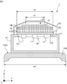
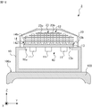
- the power conversion device 1 includes a housing 10 attached to the roof 100a of the vehicle 100 and accommodating an electronic component 11 described later, a cooling device 12 attached to the housing 10, a cooling device 12 described later, and a cover 20 covering the cooling device 12.
- the electronic component 11 indicates an arbitrary heating element such as a switching element 33a-33f, a diode, or a thyristor included in the power conversion unit 32 of FIG.
- the housing 10 accommodates the electronic component 11 and has an opening 10a at the upper part in the vertical direction.
- the opening 10a is closed by the heat receiving block 13 of the cooling device 12 described later. By closing the opening 10a with the heat receiving block 13, it is possible to prevent air, moisture, dust, and the like from flowing into the housing 10.
- the housing 10 has an opening 10a penetrating the housing 10 in the Z-axis direction in a state where the vehicle 100 is positioned horizontally.
- the housing 10 is detachably attached to the roof 100a in the vertical direction while the vehicle 100 is positioned horizontally. If the housing 10 is removable in the vertical direction, it is not necessary to remove the electronic devices located around the power conversion device 1 when the housing 10 is removed from the roof 100a for maintenance work of the power conversion device 1. , Easy to remove. Similarly, when the housing 10 is attached to the roof 100a, it is not necessary to remove the electronic devices located around the power conversion device 1, and the installation work of the housing 10 becomes easy.
- the electronic component 11 is attached to the first main surface 13a of the heat receiving block 13 included in the cooling device 12. Although the details will be described later, the electronic component 11 generates heat when energized and transfers the heat to the heat receiving block 13.
- the cooling device 12 includes a heat receiving block 13 to which the electronic component 11 is attached, and at least one heat pipe 14 which is partially attached to the heat receiving block 13 and extends in a direction away from the heat receiving block 13. A refrigerant is sealed inside each heat pipe 14.
- the cooling device 12 further preferably includes at least one fin 15 attached to the outer surface of the heat pipe 14.
- the cooling device 12 includes a heat receiving block 13, at least one heat pipe 14, and at least one fin 15.
- the unit 40 including the cooling device 12 and the electronic component 11 attached to the heat receiving block 13 of the cooling device 12 is detachable in the vertical direction while the vehicle 100 is positioned horizontally. It is preferably attached to 10.
- the unit 40 includes a heat receiving block 13, at least one heat pipe 14, at least one fin 15, and an electronic component 11 attached to the heat receiving block 13. If the unit 40 can be attached and detached in the vertical direction, it is not necessary to remove the electronic devices located around the power conversion device 1 when removing the unit 40 from the housing 10 for maintenance work of the unit 40. Becomes easier. Similarly, when the unit 40 is attached to the housing 10, it is not necessary to remove the electronic devices located around the power conversion device 1, and the attachment work of the unit 40 becomes easy.
- the upper end of the cooling device 12 in the vertical direction is higher than the upper end of the electronic device located around the power conversion device 1 in a state where the vehicle 100 is located horizontally.
- the heat receiving block 13 has a first main surface 13a and a second main surface 13b that face each other in the extending direction of the Z axis.
- the electronic component 11 is attached to the first main surface 13a.
- a heat pipe 14 is attached to the second main surface 13b. Specifically, the heat pipe 14 is inserted and fixed in the groove formed in the second main surface 13b. Further, the heat receiving block 13 is attached to the housing 10 to close the opening 10a.
- the heat receiving block 13 is made of a material having high thermal conductivity, for example, a metal such as copper or aluminum.
- the heat pipe 14 is inserted into a groove formed in the second main surface 13b of the heat receiving block 13 and attached to the heat receiving block 13. Then, the heat pipe 14 transfers the heat transferred from the electronic component 11 via the heat receiving block 13 to the traveling wind A1 described later generated by the traveling of the vehicle 100.
- the thermal conductivity of the heat pipe 14 is, for example, 5000 W / m ⁇ K, which is a sufficiently large value. Therefore, the heat pipe 14 can efficiently transfer the heat to the surrounding air by quickly transferring the heat transferred from one end fixed to the heat receiving block 13 toward the other end.
- Each heat pipe 14 has a mother pipe 14a and a plurality of branch pipes 14b communicating with the mother pipe 14a. Specifically, each heat pipe 14 has a mother pipe 14a and four branch pipes 14b.
- the mother tube 14a is inserted into a groove formed in the second main surface 13b of the heat receiving block 13, and is fixed to the heat receiving block 13 by an arbitrary fixing method such as adhesion with an adhesive or soldering.
- the mother tube 14a is fixed to the heat receiving block 13 in a partially exposed state.
- the mother tube 14a is made of a material having high thermal conductivity, for example, a metal such as copper or aluminum.
- the branch pipe 14b is fixed to the mother pipe 14a by welding, soldering, etc., and communicates with the mother pipe 14a. Further, the branch pipe 14b extends in a direction away from the heat receiving block 13, specifically, in a direction away from the second main surface 13b. In the first embodiment, the branch pipe 14b extends in the extension direction of the Z axis.
- the branch pipe 14b is made of a material having high thermal conductivity, for example, a metal such as copper or aluminum.
- each heat pipe 14 is filled with a refrigerant.
- the refrigerant exists in a gas-liquid two-phase state.
- the refrigerant is a substance that is vaporized by the heat transmitted from the electronic component 11 and liquefied by radiating heat to the air around the cooling device 12 via the heat pipe 14 and the fin 15 described later, for example, water.
- Each fin 15 is attached to the outer surface of the heat pipe 14. Specifically, the fin 15 has a through hole and is fixed to the branch pipe 14b in a state where the branch pipe 14b is passed through the through hole.
- the fin 15 is made of a material having high thermal conductivity, for example, a metal such as copper or aluminum.
- each fin 15 is formed of a flat plate member, arranged at intervals in the extending direction of the Z axis, and fixed to the branch pipe 14b.
- the cover 20 is attached to the housing 10 and covers the cooling device 12.
- the cover 20 has an arbitrary shape and an arbitrary number of ventilation ports 20a on two surfaces intersecting in the traveling direction of the vehicle 100. Specifically, the cover 20 has ventilation ports 20a penetrating the cover 20 in the X-axis direction on two surfaces orthogonal to the X-axis.
- a mechanism for cooling the electronic component 11 in the power conversion device 1 having the above configuration will be described.
- the electric power conversion unit 32 When the electric power conversion unit 32 is energized and the electronic component 11 generates heat while the vehicle 100 is traveling, heat is transferred from the electronic component 11 to the refrigerant via the heat receiving block 13 and the mother pipe 14a. As a result, the temperature of the refrigerant rises and a part of the refrigerant vaporizes.
- the vaporized refrigerant flows from the mother pipe 14a into the inside of the branch pipe 14b through one end of the branch pipe 14b, and further moves inside the branch pipe 14b toward the other end of the branch pipe 14b. In other words, the vaporized refrigerant moves in the Z-axis positive direction inside the heat pipe 14.
- the traveling wind A1 generated by the traveling of the vehicle 100 flows into the inside of the cover 20 from one ventilation port 20a of the cover 20.
- the traveling wind A1 is a ventilation port formed on one surface of the cover 20. It flows into the inside of the cover 20 from 20a.
- the traveling wind A1 flowing into the inside of the cover 20 flows in the negative direction of the X-axis while contacting the cooling device 12, specifically, the branch pipe 14b and the fin 15. Then, the traveling wind A1 flows out of the cover 20 from the ventilation port 20a formed on the other surface of the cover 20.
- the refrigerant moves inside the branch pipe 14b toward the other end of the branch pipe 14b, heat is transferred from the refrigerant to the traveling wind A1 via the branch pipe 14b and the fins 15. As the refrigerant dissipates heat, the temperature of the refrigerant drops. As a result, the refrigerant liquefies. The liquefied refrigerant flows toward one end of the branch pipe 14b and returns to the mother pipe 14a. In other words, the liquefied refrigerant flows inside the branch pipe 14b in the negative direction of the Z axis and returns to the mother pipe 14a.
- the refrigerant that has been liquefied and returned to the mother pipe 14a transfers heat from the electronic component 11 via the heat receiving block 13, it vaporizes again, flows into the branch pipe 14b, and moves toward the other end of the branch pipe 14b, in other words. Then, it moves in the positive direction of the Z axis.
- the refrigerant repeatedly vaporizes and liquefies as described above and circulates, the heat generated in the electronic component 11 is dissipated to the traveling wind A1 and the electronic component 11 is cooled.
- the electronic component 11 when the electronic component 11 generates heat and heat is transferred from the electronic component 11 to the refrigerant through the heat receiving block 13 and the mother pipe 14a, a temperature difference occurs in the unvaporized refrigerant, that is, the refrigerant in the liquid state. , Convection occurs. Due to convection, the heat transferred from the electronic component 11 is diffused and transferred in the X-axis direction, so that the electronic component 11 is efficiently cooled. The electronic component 11 is cooled by the circulation and convection of the refrigerant described above.
- the branch pipe 14b is extended as long as possible within the range of the vehicle gauge.
- the vehicle gauge indicates a cross section orthogonal to the traveling direction of the vehicle 100, that is, the maximum dimension of the vehicle 100 in the YZ plane. In other words, the vehicle 100 and the equipment mounted on the vehicle 100 are located within the vehicle gauge in the YZ plane.
- the vehicle gauge in the Z-axis direction may differ depending on the position in the Y-axis direction.
- the vehicle gauge in the Z-axis direction corresponds to the maximum dimension of the vehicle 100 in the Z-axis direction on the YZ plane.
- the maximum height of the vehicle 100 at the center in the Y-axis direction is larger than the maximum height of the vehicle 100 at the end in the Y-axis direction.
- the vertical upper end of the branch pipe 14b located at the center in the Y-axis direction is located higher than the vertical upper end of the branch pipe 14b located at the end in the Y-axis direction. Just do it.
- the branch pipe 14b can be extended as long as possible within the range of the vehicle gauge, and the cooling efficiency of the power conversion device 1 is improved.
- the fin 15 is expanded as much as possible within the range of the vehicle gauge.
- the vehicle gauge in the Y-axis direction may vary depending on the position in the Z-axis direction.
- the vehicle gauge in the Y-axis direction corresponds to the maximum dimension of the vehicle 100 in the Y-axis direction on the YZ plane.
- the width of the vehicle gauge in the Y-axis direction becomes narrower as the position in the Z-axis direction becomes higher.
- the length W1 of the fin 15 located in the upper part in the vertical direction in the Y-axis direction may be shorter than the length W2 in the Y-axis direction of the fin 15 located in the lower part in the vertical direction.
- the fins 15 can be expanded as much as possible within the range of the vehicle gauge, and the cooling efficiency of the power conversion device 1 is improved.
- the cover 20 has a shape in line with the vehicle gauge in order to extend the branch pipe 14b as long as possible or to expand the fins 15 as much as possible within the range of the vehicle gauge.
- the downstream temperature is higher than the upstream temperature.
- the cooling efficiency of the heat pipe 14 located in the rear of the vehicle 100 in the traveling direction is lower than the cooling efficiency of the heat pipe 14 located in the front of the vehicle 100 in the traveling direction. Therefore, a temperature difference may occur in the electronic component 11 depending on the position where the heat receiving block 13 is attached. Therefore, it is preferable that the mother pipe 14a extends in the direction in which the traveling wind A1 flows, that is, in the X-axis direction.
- the heat transferred from the electronic component 11 is diffused and transmitted in the X-axis direction by convection of the refrigerant in the liquid state, so that the electronic component 11 The occurrence of temperature difference is suppressed.
- each fin 15 extends along the direction in which the traveling wind A1 flows, that is, the X-axis direction.
- the traveling wind A1 flowing in from the ventilation port 20a smoothly flows along the fins 15, so that the cooling efficiency of the power conversion device 1 is improved.
- the main surface of each fin 15 extends along the X-axis direction, and each fin 15 is positioned horizontally while the vehicle 100 is positioned horizontally.
- the ratio of the length of at least one of the fins 15 in the Y-axis direction to the vehicle body width W3 of the vehicle 100 described later is preferably equal to or more than the threshold value.
- the threshold value may be determined according to the cooling performance required for the cooling device 12, and is, for example, 0.5.
- the length W2 of the lower fin 15 in the vertical direction in the Y-axis direction accounts for 0.5 or more of the vehicle body width W3 of the vehicle 100.
- the size of the fins 15 can be adjusted to the side surface of the conventional power conversion device mounted under the floor of the railway vehicle. It can be made larger than the fins of the provided cooling device. By enlarging the fin 15, heat can be transferred to the traveling wind A1 more efficiently. As a result, the cooling efficiency of the power conversion device 1 becomes higher than the cooling efficiency of the conventional power conversion device.
- the Y-axis of the fin 15 is used. If the length in the direction is increased, the length of the fin 15 in the X-axis direction can be shortened. If the length of the fins 15 in the X-axis direction, that is, in the direction in which the traveling wind A1 flows is shortened, the pressure loss becomes small, and more traveling wind A1 can be passed between the fins 15. As a result, it is possible to improve the cooling efficiency of the power conversion device 1 by using the fins 15 having the same area of the main surface as the conventional fins.
- the power conversion device 1 is installed on the roof 100a of the vehicle 100 and extends in a direction away from the heat receiving block 13 that closes the opening 10a formed in the upper portion of the housing 10 in the vertical direction.
- the heat pipe 14 and the fins 15 attached to the heat pipe 14 are provided.
- the number of motor vehicles equipped with electric motors is small, in other words, in the case of centralized formation, electric motors with high output are adopted, so power is supplied to the electric motors.
- the output of the power converter is also increased, and the amount of heat generated is increased.
- a blower was used to forcibly supply wind to cool the power converter.
- the electronic component 11 of the power conversion device 1 is cooled by using the traveling wind A1 without using a fan, a blower, or the like. Is possible.
- the power conversion device 1 may be provided at a location other than the upper end of the roof 100a of the vehicle 100 in the vertical direction.
- the power conversion device 1 provided in the accommodating portion 100b provided on the roof 100a of the vehicle 100 will be described in the second embodiment.
- the accommodating portion 100b formed integrally with the roof 100a will be taken as an example, and the accommodating portion 100b accommodating the power conversion device 1 and the power conversion device 1 will be described.
- the roof 100a of the vehicle 100 is formed with a housing portion 100b, which is a recess in which the upper portion in the vertical direction is open.
- the accommodating portion 100b has an open upper surface in the vertical direction in a state where the vehicle 100 is positioned horizontally.
- the accommodating portion 100b accommodates the housing 10 of the power conversion device 1.
- the bottom surface of the housing 10 is attached to the bottom surface of the accommodating portion 100b.
- the mechanism for cooling the components of the power conversion device 1 and the electronic component 11 is the same as that of the first embodiment.
- At least one of the upper ends of the heat pipe 14 in the vertical direction is located higher than the upper end of the roof 100a in the vertical direction when the vehicle 100 is located horizontally.
- the upper end of each heat pipe 14 in the vertical direction is located higher than the upper end of the roof 100a in the vertical direction. Therefore, even if the power conversion device 1 is provided in the accommodating portion 100b, the traveling wind A1 can come into contact with each heat pipe 14, and the electronic component 11 can be cooled.
- At least one of the fins 15 is located higher than the upper end of the roof 100a in the vertical direction in a state where the vehicle 100 is positioned horizontally. As shown in FIGS. 6 and 7, in the second embodiment, each fin 15 is located higher than the upper end of the roof 100a in the vertical direction. Therefore, even if the power conversion device 1 is provided in the accommodating portion 100b, the traveling wind A1 can come into contact with each fin 15, and the electronic component 11 can be cooled.
- the power conversion device 1 can cool the electronic component 11 even if it is installed in the accommodating portion 100b formed on the roof 100a of the vehicle 100.
- the power conversion device 1 can be arranged on the roof 100a and the electronic component 11 can be cooled. Become.
- the power conversion device 1 includes a wind guide member 21 provided at a position adjacent to the outer surface of the housing 10 intersecting the traveling direction of the vehicle 100, that is, the X-axis direction.
- the wind guide member 21 guides the traveling wind A1 to the cooling device 12.
- the air guide member 21 guides the traveling wind A1 to the heat pipe 14 and the fins 15 through the ventilation port 20a formed in the cover 20.
- the two wind guide members 21 are arranged side by side in the X-axis direction with the housing 10 interposed therebetween.
- the wind guide member 21 has the shape of a cylinder whose penetrating direction is along the X-axis direction and whose side surfaces are notched.
- 9 is a cross-sectional view taken along the line CC of FIG. Specifically, the wind guide member 21 has the shape of a square cylinder with a notched side surface.
- the wind guide member 21 is attached to the roof 100a so that the notched portion of the cylinder faces the roof 100a.
- the wind guide member 21 is attached to the bottom surface of the accommodating portion 100b in which the cut portion of the cylinder is formed on the roof 100a.
- the air guide member 21 is attached to the roof 100a to form a ventilation path 21a that guides the traveling wind A1 to the cooling device 12 with the roof 100a.
- the ventilation member 21 forms a ventilation passage 21a conducting in the X-axis direction in order to guide the traveling wind A1 to the heat pipe 14 and the fins 15 through the ventilation port 20a formed in the cover 20.
- the area of the end face of the ventilation passage 21a formed by the ventilation member 21 near the housing 10 is smaller than the area of the end face of the ventilation passage 21a far from the housing 10. In this case, the traveling wind A1 flowing along the roof 100a can be efficiently guided to the heat pipe 14 and the fins 15.
- the traveling wind A1 can be efficiently guided to the cooling device 12.
- the power conversion device 1 may include two wind guide members 21 provided side by side in the X-axis direction with the housing 10 sandwiched therein.
- the wind guide member 21 may be provided at the upper end of the roof 100a in the vertical direction while the vehicle 100 is located horizontally.
- the power supplied to the power converter 1 is not limited to DC power.
- the power conversion device 1 may be a converter that converts AC power into DC power.
- the power supplied by the power converter 1 to the load is not limited to the three-phase AC power.
- the power converter 1 may supply DC power to a load that is a DC motor.
- the motor M1 is not limited to the three-phase induction motor, but may be a synchronous motor, a DC motor, or the like. Further, the power conversion device 1 is not limited to the self-cooling type power conversion device that supplies power to the electric motor M1. As an example, the load supplied by the power conversion device 1 is an arbitrary electronic device that consumes electric power, such as a lighting device and an air conditioning device.
- the power conversion device 1 is not limited to a railroad vehicle, and can be mounted on an arbitrary moving body such as a trolleybus or a tram in which a running wind A1 is generated.
- the shape of the housing 10 is arbitrary as long as it accommodates the electronic component 11 inside and can be attached to the roof 100a.
- the vertical upper surface of the housing 10 may be tilted with respect to the horizontal plane with the vehicle 100 positioned horizontally.
- the housing 10 has an upper surface inclined toward the front in the traveling direction of the vehicle. As a result, the running wind A1 can be efficiently brought into contact with the heat pipe 14 and the fins 15.
- the heat receiving block 13 may be formed of a single plate-shaped member or may be formed by combining a plurality of plate-shaped members. By forming the heat receiving block 13 with a single plate-shaped member, the manufacturing process of the power conversion device 1 can be simplified, and the airtightness of the housing 10 can be improved.
- the shape of the heat pipe 14 is arbitrary as long as it is a shape that enables the electronic component 11 to be cooled by the circulation of the refrigerant sealed inside.
- the power conversion device 2 shown in FIG. 10 includes a heat pipe 22 bent in an L shape. A part of the heat pipe 22 extends in the X-axis direction, and the other part extends in the Z-axis direction.
- the power conversion device 2 may be provided in the accommodating portion 100b formed on the roof 100a, as in the second embodiment.
- the shape of the heat pipe 14 may be U-shaped or annular.
- the shape of the cross section orthogonal to the stretching direction of the heat pipe 14 is not limited to a circular shape, and may be a flat shape.
- the shape of the cross section of the mother pipe 14a and the branch pipe 14b orthogonal to the extending direction may be circular or flat.
- the flat shape is a shape obtained by deforming a part of the width of the circle to be narrower than the original circle, and includes an ellipse, a streamlined shape, an oval, and the like.
- the oval means a shape in which the outer edges of circles having the same diameter are connected by a straight line.
- the heat pipe 14 may communicate with the groove formed in the heat receiving block 13.
- the heat pipe 14 may have a tubular shape with one end closed.
- the number of heat pipes 14 is not limited to the above example, and is arbitrary.
- the number of mother pipes 14a and the number of branch pipes 14b attached to each mother pipe 14a are not limited to the above examples, and are arbitrary.
- the positions of the upper ends of the heat pipes 14 in the vertical direction may be different as shown in the embodiment, or may be the same as each other.
- the number of fins 15 is not limited to the above example and is arbitrary.
- the length of the width of the fins 15 in the Y-axis direction may be different as shown in the embodiment, or may be the same as each other.
- the shape of the fin 15 is not limited to the above example, and is arbitrary.
- the fin 15 may be formed of a flat plate member or a bent plate-shaped member as shown in the embodiment.
- the fins 15 formed of one plate-shaped member are arranged side by side in the Z-axis direction.
- the shape of the fins 15 is not limited to the above example, and each fin 15 may be formed of a plurality of plate-shaped members.
- the cooling device 12 included in the power conversion device 3 shown in FIG. 12, which is a cross-sectional view taken along the line DD of FIGS. 11 and 11, has a plurality of fins 23.
- Each fin 23 is formed of flat plate members 23a and 23b.
- Each fin 15 may be formed of the same member as each other, or at least one of the fins 15 may be formed of a member different from the other fins 15.
- the thermal conductivity of at least one of the fins 15 is different from the thermal conductivity of the other fins 15.
- the thermal conductivity of the fins 15 located in the upper part in the vertical direction is preferably higher than the thermal conductivity of the fins 15 located in the lower part in the vertical direction.
- the upper fin 15 in the vertical direction may be formed of copper
- the lower fin 15 in the vertical direction may be formed of aluminum.
- the fin 15 located at the upper part in the vertical direction can easily come into contact with the traveling wind A1 even if other equipment is provided around the power conversion device 1. Therefore, by increasing the thermal conductivity of the fins 15 located at the upper part in the vertical direction, it is possible to improve the cooling efficiency of the power conversion device 1.
- the shape of the cover 20 is arbitrary as long as it covers the cooling device 12 and allows the running wind A1 to flow into the inside.
- the cover 20 may have a curved upper surface in the vertical direction.
- the cover 20 may have a flat upper surface in the vertical direction.
- the cover 20 preferably has a shape that maximizes the internal space within the range of the vehicle gauge.
- the shape of the air guide member 21 is not limited to the square cylinder whose side surface is cut out, and is arbitrary as long as it can guide the traveling wind A1 to the cooling device 12.
- the air guide member 21 may have a cylindrical shape with a notched side surface.
- the wind guide member 21 may have the shape of a cylinder having a part of the side surface attached to the roof 100a and having a polygonal cross section.
- the wind guide member 21 may be provided separately from each of the housing 10 and the cover 20, or may be provided in contact with at least one of the housing 10 and the cover 20. You may.
- the number of wind guide members 21 is arbitrary.
- one wind guide member 21 may be provided in front of the traveling direction of the vehicle.
- the switching elements 33a-33f may be formed of a wide bandgap semiconductor.
- Wide bandgap semiconductors include, for example, silicon carbide, gallium nitride based materials, or diamond.
- the opening surface of the accommodating portion 100b may be positioned horizontally or may be inclined with respect to the horizontal plane in a state where the vehicle 100 is positioned horizontally.
- the accommodating portion 100b may be formed separately from the roof 100a.
- the accommodating portion 100b may be a pair of roof coverings 100c facing each other in the width direction.
- the main surfaces of the pair of roof covers 100c face each other in the width direction.
- each of the pair of roof covers 100c may be a plate-shaped member having a flat main surface or a plate-shaped member having a curved main surface.
- the power conversion device 1-3 may further include a sealing member that surrounds the opening 10a and abuts on each of the housing 10 and the heat receiving block 13. By providing the sealing member, the airtightness of the housing 10 is enhanced.
- 1,2,3 power converter 10 housing, 10a opening, 11 electronic parts, 12 cooling device, 13 heat receiving block, 13a first main surface, 13b second main surface, 14,22 heat pipe, 14a mother tube , 14b branch pipe, 15, 23 fins, 20 cover, 20a ventilation port, 21 ventilation member, 21a ventilation path, 23a, 23b flat plate member, 31a, 31b primary terminal, 32 power converter, 33a, 33b, 33c, 33d, 33e, 33f switching element, 40 units, 100 vehicles, 100a roof, 100b housing, 100c roof cover, A1 running wind, FC1 filter capacitor, M1 electric power, W1, W2 length, W3 body width.
Landscapes
- Engineering & Computer Science (AREA)
- Microelectronics & Electronic Packaging (AREA)
- Physics & Mathematics (AREA)
- Thermal Sciences (AREA)
- Power Engineering (AREA)
- Cooling Or The Like Of Electrical Apparatus (AREA)
- Electric Propulsion And Braking For Vehicles (AREA)
- Inverter Devices (AREA)
Abstract
電力変換装置(1)は、車両(100)の屋根(100a)に設置される筐体(10)と、受熱ブロック(13)と、少なくとも1つのヒートパイプ(14)とを備える。筐体(10)は、電子部品(11)を収容し、鉛直方向上部に開口部(10a)を有する。受熱ブロック(13)の一方の主面である第1主面(13a)に、電子部品(11)が取り付けられる。受熱ブロック(13)は、筐体(10)に取り付けられて開口部(10a)を塞ぐ。少なくとも1つのヒートパイプ(14)は、受熱ブロック(13)の他方の主面である第2主面(13b)に取り付けられ、受熱ブロック(13)から離れる方向に延伸し、内部に冷媒が封入される。
Description
本開示は、電力変換装置に関する。
車両に搭載される電力変換装置には、通電時の発熱による電子部品の損傷を防ぐため、発熱体である電子部品に熱的に接続された冷却装置を有するものがある。冷却装置は、電子部品から伝達された熱を、車両の走行によって生じる走行風に放熱することで、電子部品を冷却する。この種の電力変換装置の一例が特許文献1に開示されている。特許文献1に開示されている電力変換装置は、鉄道車両の床下に取り付けられ、枕木方向に交差する側面に取り付けられた冷却装置を有する。
鉄道車両の床下には、電力変換装置の他に、変圧器、空調機器等の多数の機器が設置されているためスペースの制約があり、冷却装置が有するヒートパイプおよびフィンを大きくして、走行風に接触する面を拡大することが難しい。また上述したように鉄道車両の床下に設置されている多数の機器によって、走行風をフィンの間に効率的に通すことが難しい。この結果、ブロワ、ファン等を備えずに、走行風に熱を伝達することで電子部品を冷却する自冷式の電力変換装置の冷却効率を高めることが困難となることがある。
本開示は上述の事情に鑑みてなされたものであり、冷却効率が高い電力変換装置を提供することを目的とする。
上記目的を達成するために、本開示の電力変換装置は、電力変換部と、筐体と、受熱ブロックと、少なくとも1つのヒートパイプと、を備える。電力変換部は、供給された電力を、負荷に供給するための電力に変換して、変換した電力を負荷に供給する。筐体は、電力変換部が有する電子部品を収容し、鉛直方向上部に開口部を有する。また筐体は、車両の屋根に設置される。受熱ブロックの一方の主面には、電子部品が取り付けられる。また受熱ブロックは、筐体に取り付けられて開口部を塞ぐ。少なくとも1つのヒートパイプは、受熱ブロックの他方の主面に取り付けられ、受熱ブロックから離れる方向に延伸し、内部に冷媒が封入される。
本開示に係る電力変換装置が有するヒートパイプは、車両の屋根に設けられるため、電子部品で生じた熱を走行風に効率的に伝達することが可能となる。この結果、電力変換装置の冷却性能を高めることが可能となる。
以下、本開示の実施の形態に係る電力変換装置について図面を参照して詳細に説明する。なお図中、同一または同等の部分には同一の符号を付す。
(実施の形態1)
鉄道車両の屋根に搭載され、走行風を利用して電子部品を冷却する自冷式の電力変換装置を例にして、実施の形態1に係る電力変換装置について説明する。
図1に示す電力変換装置1は、図示しない電源から供給される直流電力を負荷である電動機M1に供給するための三相交流電力に変換し、三相交流電力を電動機M1に供給する。なお電源は、例えば、架線から電力を取得する集電装置である。また電動機M1は、例えば、三相誘導電動機である。
鉄道車両の屋根に搭載され、走行風を利用して電子部品を冷却する自冷式の電力変換装置を例にして、実施の形態1に係る電力変換装置について説明する。
図1に示す電力変換装置1は、図示しない電源から供給される直流電力を負荷である電動機M1に供給するための三相交流電力に変換し、三相交流電力を電動機M1に供給する。なお電源は、例えば、架線から電力を取得する集電装置である。また電動機M1は、例えば、三相誘導電動機である。
詳細には、電力変換装置1は、電源に接続される一次端子31aと、接地される一次端子31bと、両端が一次端子31a,31bに接続され、リップルを除去するフィルタコンデンサFC1と、電源から供給される直流電力を三相交流電力に変換して電動機M1に供給する電力変換部32と、を備える。電力変換部32は、U相に対応するスイッチング素子33a,33bと、V相に対応するスイッチング素子33c,33dと、W相に対応するスイッチング素子33e,33fと、を有する。図示しないスイッチング制御部がスイッチング素子33a-33fのオンオフを切り替えることで、電力変換部32は、電源から供給される直流電力を三相交流電力に変換して電動機M1に供給する。
電力変換装置1は、図2に示すように車両100の屋根100aの上に設けられる。詳細には、電力変換装置1は、車両100が水平に位置している状態で、屋根100aの鉛直方向上端に取り付けられる。図2において、X軸は、車両100の進行方向を示す。換言すれば、車両100はX軸正方向またはX軸負方向に進む。Y軸は、車両100の幅方向、換言すれば、枕木方向を示す。またZ軸は、X軸およびY軸のそれぞれに直交する。なお車両100が水平に位置している状態で、Z軸は鉛直方向を示す。
電力変換装置1は、車両100の屋根100aに取り付けられ、後述の電子部品11を収容する筐体10と、筐体10に取り付けられる後述の冷却装置12と、冷却装置12を覆うカバー20と、を備える。なお電子部品11は、図1の電力変換部32が有するスイッチング素子33a-33f、ダイオード、サイリスタ等の任意の発熱体を示すものとする。
図3および図3のA-A線での矢視断面図である図4に示すように、筐体10は、電子部品11を収容し、鉛直方向上部に開口部10aを有する。開口部10aは、後述の冷却装置12の受熱ブロック13によって塞がれる。開口部10aが受熱ブロック13によって塞がれることで、筐体10の内部に空気、水分、塵埃等が流入することが抑制される。実施の形態1では、筐体10は、車両100が水平に位置している状態で、Z軸方向に筐体10を貫通している開口部10aを有する。
また筐体10は、車両100が水平に位置している状態で、鉛直方向に着脱可能に屋根100aに取り付けられることが好ましい。筐体10が鉛直方向に着脱可能であれば、電力変換装置1の保守作業のため、筐体10を屋根100aから取り外す際に、電力変換装置1の周囲に位置する電子機器の取り外しが不要となり、取り外し作業が容易となる。同様に、筐体10を屋根100aに取り付ける際に、電力変換装置1の周囲に位置する電子機器の取り外しが不要となり、筐体10の取り付け作業が容易となる。
電子部品11は、冷却装置12が有する受熱ブロック13の第1主面13aに取り付けられる。詳細については後述するが、電子部品11は、通電されると発熱し、熱を受熱ブロック13に伝達する。
冷却装置12は、電子部品11が取り付けられる受熱ブロック13と、一部が受熱ブロック13に取り付けられ、受熱ブロック13から離れる方向に延伸する少なくとも1つのヒートパイプ14と、を備える。各ヒートパイプ14の内部には冷媒が封入される。冷却装置12はさらに、ヒートパイプ14の外面に取り付けられる少なくとも1つのフィン15を備えることが好ましい。実施の形態1では、冷却装置12は、受熱ブロック13と、少なくとも1つのヒートパイプ14と、少なくとも1つのフィン15と、を備えるものとする。
また冷却装置12と、冷却装置12の受熱ブロック13に取り付けられた状態の電子部品11と、を含むユニット40は、車両100が水平に位置している状態で、鉛直方向に着脱可能に筐体10に取り付けられることが好ましい。なおユニット40は、詳細には、受熱ブロック13と、少なくとも1つのヒートパイプ14と、少なくとも1つのフィン15と、受熱ブロック13に取り付けられた状態の電子部品11と、を含む。ユニット40が鉛直方向に着脱可能であれば、ユニット40の保守作業のため、ユニット40を筐体10から取り外す際に、電力変換装置1の周囲に位置する電子機器の取り外しが不要となり、取り外し作業が容易となる。同様に、ユニット40を筐体10に取り付ける際に、電力変換装置1の周囲に位置する電子機器の取り外しが不要となり、ユニット40の取り付け作業が容易となる。
なお冷却装置12の鉛直方向上端は、車両100が水平に位置している状態で、電力変換装置1の周囲に位置する電子機器の鉛直方向上端よりも高い位置にあることが好ましい。冷却装置12の鉛直方向上端を周囲に位置する電子機器の鉛直方向上端よりも高くに配置することで、電力変換装置1の冷却効率が高まる。
上記構成を有する冷却装置12の各部について、冷却装置12が8個のヒートパイプ14を備える構成を例にして説明する。
受熱ブロック13は、Z軸の延伸方向に対向する第1主面13aおよび第2主面13bを有する。第1主面13aには、電子部品11が取り付けられる。第2主面13bには、ヒートパイプ14が取り付けられる。詳細には、第2主面13bに形成された溝に、ヒートパイプ14が挿入され、固定される。また受熱ブロック13は、筐体10に取り付けられることで、開口部10aを塞ぐ。なお受熱ブロック13は、熱伝導率の高い材料、例えば、銅、アルミニウム等の金属で形成される。
受熱ブロック13は、Z軸の延伸方向に対向する第1主面13aおよび第2主面13bを有する。第1主面13aには、電子部品11が取り付けられる。第2主面13bには、ヒートパイプ14が取り付けられる。詳細には、第2主面13bに形成された溝に、ヒートパイプ14が挿入され、固定される。また受熱ブロック13は、筐体10に取り付けられることで、開口部10aを塞ぐ。なお受熱ブロック13は、熱伝導率の高い材料、例えば、銅、アルミニウム等の金属で形成される。
ヒートパイプ14は、受熱ブロック13の第2主面13bに形成された溝に挿入され、受熱ブロック13に取り付けられる。そして、ヒートパイプ14は、受熱ブロック13を介して電子部品11から伝達された熱を、車両100の走行によって生じる後述の走行風A1に伝達する。なおヒートパイプ14の熱伝導率は、例えば5000W/m・Kと十分に大きい値である。このため、ヒートパイプ14は、受熱ブロック13に固定された一端から伝えられた熱を、速やかに他端に向けて伝達することで、周囲の空気に熱を効率よく伝達することができる。
ヒートパイプ14の構造について詳細に説明する。各ヒートパイプ14は、母管14aと、母管14aに連通する複数の支管14bとを有する。詳細には、各ヒートパイプ14は、母管14aと、4つの支管14bと、を有する。母管14aは、受熱ブロック13の第2主面13bに形成された溝に挿入され、接着剤による接着、はんだ付け等の任意の固定方法によって、受熱ブロック13に固定されている。なお母管14aは、一部が露出した状態で受熱ブロック13に固定されている。また母管14aは、熱伝導率の高い材料、例えば、銅、アルミニウム等の金属で形成される。
支管14bは、溶接、はんだ付け等によって、母管14aに固定され、母管14aに連通している。また支管14bは、受熱ブロック13から離れる方向、詳細には、第2主面13bから離れる方向に延びる。実施の形態1では、支管14bは、Z軸の延伸方向に延伸する。なお支管14bは、熱伝導率の高い材料、例えば、銅、アルミニウム等の金属で形成される。
また各ヒートパイプ14には、冷媒が封入される。常温では、冷媒は気液二相の状態で存在する。なお冷媒は、電子部品11から伝達される熱で気化し、ヒートパイプ14および後述のフィン15を介して冷却装置12の周囲の空気に放熱することで液化する物質、例えば、水である。
各フィン15は、ヒートパイプ14の外面に取り付けられる。詳細には、フィン15は、貫通孔を有し、貫通孔に支管14bが通された状態で、支管14bに固定される。なおフィン15は、熱伝導率の高い材料、例えば、銅、アルミニウム等の金属で形成される。実施の形態1では、各フィン15は平板部材で形成され、Z軸の延伸方向に間隔を空けて配置され、支管14bに固定される。
カバー20は、筐体10に取り付けられ、冷却装置12を覆う。なおカバー20は、車両100の進行方向に交差する二面に、任意の形状であって、任意の個数の通風口20aを有する。詳細には、カバー20は、X軸に直交する二面に、カバー20をX軸方向に貫通する通風口20aを有する。
上記構成を有する電力変換装置1において、電子部品11が冷却される仕組みについて説明する。車両100の走行時に電力変換部32が通電されて電子部品11が発熱すると、電子部品11から受熱ブロック13および母管14aを介して、冷媒に熱が伝達される。その結果、冷媒の温度が上昇し、冷媒の一部が気化する。気化した冷媒は、母管14aから支管14bの一端を介して支管14bの内部に流入し、さらに支管14bの内部を支管14bの他端に向かって移動する。換言すれば、気化した冷媒は、ヒートパイプ14の内部をZ軸正方向に移動する。
なお車両100の走行時には、車両100の走行に伴って生じる走行風A1が、カバー20の一方の通風口20aからカバー20の内部に流入する。例えば車両100がX軸正方向に走行している場合、図3に示すように、X軸負方向に流れる走行風A1が生じ、走行風A1がカバー20の一方の面に形成された通風口20aからカバー20の内部に流入する。カバー20の内部に流入した走行風A1は、冷却装置12、詳細には、支管14bおよびフィン15に接触しながらX軸負方向に流れる。そして、走行風A1はカバー20の他方の面に形成された通風口20aからカバー20の外部に流出する。
上述したように、冷媒が支管14bの内部を支管14bの他端に向かって移動する間に、支管14bおよびフィン15を介して、冷媒から走行風A1に熱が伝達される。冷媒が放熱することで、冷媒の温度は下がる。この結果、冷媒は、液化する。液化した冷媒は、支管14bの一端に向かって流れ、母管14aに戻る。換言すれば、液化した冷媒は、支管14bの内部をZ軸負方向に流れ、母管14aに戻る。液化して母管14aに戻った冷媒は、受熱ブロック13を介して電子部品11から熱を伝達されると、再び気化し、支管14bに流入し、支管14bの他端に向かって移動、換言すればZ軸正方向に移動する。冷媒が上述の気化と液化を繰り返して循環することで、電子部品11で生じた熱は、走行風A1に放熱されて、電子部品11は冷却される。
また電子部品11が発熱し、電子部品11から受熱ブロック13および母管14aを介して冷媒に熱が伝達されると、気化しなかった冷媒、すなわち、液体の状態の冷媒に温度差が生じて、対流が生じる。対流によって、冷媒が、電子部品11から伝達された熱はX軸方向に拡散して伝達されるため、電子部品11は効率よく冷却される。
上述した冷媒の循環と対流によって、電子部品11が冷却される。
上述した冷媒の循環と対流によって、電子部品11が冷却される。
電力変換装置1の冷却効率を高めるために、支管14bは、車両限界の範囲で、できる限り長く延伸することが好ましい。なお車両限界は、車両100の進行方向に直交する断面、すなわちYZ平面における車両100の最大寸法を示す。換言すれば、車両100および車両100に搭載される機器は、YZ平面において、車両限界の範囲内に位置する。
Z軸方向の車両限界は、Y軸方向の位置によって異なることがある。なおZ軸方向の車両限界は、YZ平面における車両100のZ軸方向の最大寸法に相当する。例えば、Y軸方向の中央での車両100の高さの最大値は、Y軸方向の端部での車両100の高さの最大値より大きい。この場合、車両100が水平に位置している状態で、Y軸方向の中央に位置する支管14bの鉛直方向上端は、Y軸方向の端部に位置する支管14bの鉛直方向上端より高く位置すればよい。これにより、車両限界の範囲で、支管14bをできる限り長く延伸することが可能となり、電力変換装置1の冷却効率が向上する。
同様に、フィン15は、車両限界の範囲で、できる限り拡大することが好ましい。Y軸方向の車両限界は、Z軸方向の位置によって異なることがある。なおY軸方向の車両限界は、YZ平面における車両100のY軸方向の最大寸法に相当する。例えば、屋根100aの上部では、Z軸方向の位置が高くなるにつれて、Y軸方向の車両限界の幅は狭くなる。この場合、鉛直方向上部に位置するフィン15のY軸方向の長さW1は、鉛直方向下部に位置するフィン15のY軸方向の長さW2より短ければよい。これにより、車両限界の範囲で、フィン15をできる限り拡大することが可能となり、電力変換装置1の冷却効率が向上する。
なお車両限界の範囲で、支管14bをできる限り長く延伸するため、または、フィン15をできる限り拡大するために、カバー20を車両限界に沿った形状とすることが好ましい。
上述したように走行風A1は、ヒートパイプ14およびフィン15から熱を伝達されるため、下流の温度が上流の温度より高い。換言すれば、車両100の進行方向後方に位置するヒートパイプ14の冷却効率は、車両100の進行方向前方に位置するヒートパイプ14の冷却効率より低い。このため、受熱ブロック13に取り付けられる位置によって、電子部品11に温度差が生じることがある。そこで、母管14aは、走行風A1の流れる方向、すなわちX軸方向に延伸することが好ましい。母管14aがX軸方向に延伸していると、液体の状態の冷媒が対流することで、電子部品11から伝達された熱はX軸方向に拡散して伝達されるため、電子部品11の温度差が生じることが抑制される。
また各フィン15の主面は、走行風A1の流れる方向、すなわちX軸方向に沿って延伸することが好ましい。この場合、通風口20aから流入した走行風A1がスムーズにフィン15に沿って流れるため、電力変換装置1の冷却効率が向上する。例えば、実施の形態1では、各フィン15の主面はX軸方向に沿って延伸し、車両100が水平に位置している状態で、各フィン15は水平に位置する。
またフィン15の少なくともいずれかのY軸方向の長さが、後述の車両100の車体幅W3に占める割合は、閾値以上であることが好ましい。閾値は、冷却装置12に求められる冷却性能に応じて定められればよく、例えば0.5である。実施の形態1では、図4に示すように、鉛直方向下部のフィン15のY軸方向の長さW2が、車両100の車体幅W3に占める割合は0.5以上である。フィン15のY軸方向の長さが車両100の車体幅W3に占める割合を閾値以上とすることで、フィン15の大きさは、鉄道車両の床下に取り付けられた従来の電力変換装置の側面に設けられている冷却装置が有するフィンよりも大きくすることができる。フィン15を大きくすることで、より効率的に走行風A1に熱を伝達することが可能となる。この結果、電力変換装置1の冷却効率は、従来の電力変換装置の冷却効率より高くなる。
フィン15の主面の面積を、鉄道車両の床下に取り付けられた従来の電力変換装置の側面に設けられている冷却装置が有するフィンの主面の面積と同じにする場合、フィン15のY軸方向の長さを長くすれば、フィン15のX軸方向の長さを短くすることができる。X軸方向、すなわち、走行風A1の流れる方向におけるフィン15の長さを短くすると、圧力損失が小さくなり、より多くの走行風A1をフィン15の間に通すことが可能となる。この結果、従来のフィンと主面の面積が同じフィン15を用いて電力変換装置1の冷却効率を向上させることが可能となる。
以上説明した通り、実施の形態1に係る電力変換装置1は、車両100の屋根100aに設置され、筐体10の鉛直方向上部に形成された開口部10aを塞ぐ受熱ブロック13から離れる方向に延伸するヒートパイプ14と、ヒートパイプ14に取り付けられたフィン15と、を備える。車両100の屋根100aの上にヒートパイプ14およびフィン15を設けることで、電子部品11で生じた熱を走行風A1に効率的に伝達することが可能となる。この結果、電力変換装置1の冷却性能を高めることが可能となる。
鉄道車両に含まれる複数の車両の内、電動機が搭載されている動力車の数が少ない、換言すれば、集中型の編成の場合、出力が大きい電動機が採用されるため、電動機に電力を供給する電力変換装置の出力も大きくなり、発熱量が増える。従来は、集中型の編成の場合は、ブロワを用いて強制的に風を供給し電力変換装置の冷却を行っていた。実施の形態1に係る電力変換装置1によれば、集中型の編成の場合でも、ファン、ブロワ等を用いることなく、走行風A1を利用して電力変換装置1の電子部品11を冷却することが可能となる。
(実施の形態2)
電力変換装置1は、車両100の屋根100aの鉛直方向上端以外の場所に設けられてもよい。一例として、車両100の屋根100aに設けられた収容部100bに設けられる電力変換装置1について実施の形態2で説明する。なお実施の形態2では、屋根100aと一体に形成された収容部100bを例にして、電力変換装置1と電力変換装置1を収容する収容部100bについて説明する。
電力変換装置1は、車両100の屋根100aの鉛直方向上端以外の場所に設けられてもよい。一例として、車両100の屋根100aに設けられた収容部100bに設けられる電力変換装置1について実施の形態2で説明する。なお実施の形態2では、屋根100aと一体に形成された収容部100bを例にして、電力変換装置1と電力変換装置1を収容する収容部100bについて説明する。
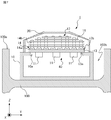
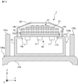
図5に示すように、車両100の屋根100aには、鉛直方向上部が開口している凹部である収容部100bが形成されている。詳細には、収容部100bは、車両100が水平に位置している状態で、鉛直方向上面が開口している。収容部100bは、電力変換装置1の筐体10を収容する。詳細には、収容部100bの底面に筐体10の底面が取り付けられる。なお電力変換装置1の構成要素および電子部品11を冷却する仕組みは、実施の形態1と同様である。
走行風A1を利用して電子部品11を冷却するための電力変換装置1の構造について詳細に説明する。
ヒートパイプ14の少なくともいずれかの鉛直方向上端は、車両100が水平に位置している状態で、屋根100aの鉛直方向上端より高く位置する。図6および図7に示すように、実施の形態2では、各ヒートパイプ14の鉛直方向上端は、屋根100aの鉛直方向上端より高く位置する。このため、電力変換装置1が収容部100bに設けられていても、各ヒートパイプ14に走行風A1が接触することが可能となり、電子部品11を冷却することが可能となる。
ヒートパイプ14の少なくともいずれかの鉛直方向上端は、車両100が水平に位置している状態で、屋根100aの鉛直方向上端より高く位置する。図6および図7に示すように、実施の形態2では、各ヒートパイプ14の鉛直方向上端は、屋根100aの鉛直方向上端より高く位置する。このため、電力変換装置1が収容部100bに設けられていても、各ヒートパイプ14に走行風A1が接触することが可能となり、電子部品11を冷却することが可能となる。
またフィン15の少なくともいずれかは、車両100が水平に位置している状態で、屋根100aの鉛直方向上端より高く位置する。図6および図7に示すように、実施の形態2では、各フィン15は、屋根100aの鉛直方向上端より高く位置する。このため、電力変換装置1が収容部100bに設けられていても、各フィン15に走行風A1が接触することが可能となり、電子部品11を冷却することが可能となる。
以上説明した通り、実施の形態2に係る電力変換装置1は、車両100の屋根100aに形成された収容部100bに設置されても、電子部品11を冷却することが可能となる。例えば、車両限界に対する車両100の大きさが大きい場合に、屋根100aに収容部100bを形成することで、電力変換装置1を屋根100aの上に配置し、電子部品11を冷却することが可能となる。
(実施の形態3)
カバー20の内部に、より効果的に走行風A1を取り入れるために、導風部材21を備える電力変換装置について実施の形態3で説明する。
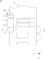
図8に示すように、電力変換装置1は、車両100の進行方向、すなわちX軸方向に交差する筐体10の外面に隣接した位置に設けられる導風部材21を備える。導風部材21は、走行風A1を冷却装置12に導く。詳細には、導風部材21は、カバー20に形成された通風口20aを介して、走行風A1をヒートパイプ14およびフィン15に導く。なお実施の形態3では、2つの導風部材21が、筐体10を挟んでX軸方向に並べて配置される。
カバー20の内部に、より効果的に走行風A1を取り入れるために、導風部材21を備える電力変換装置について実施の形態3で説明する。
図8に示すように、電力変換装置1は、車両100の進行方向、すなわちX軸方向に交差する筐体10の外面に隣接した位置に設けられる導風部材21を備える。導風部材21は、走行風A1を冷却装置12に導く。詳細には、導風部材21は、カバー20に形成された通風口20aを介して、走行風A1をヒートパイプ14およびフィン15に導く。なお実施の形態3では、2つの導風部材21が、筐体10を挟んでX軸方向に並べて配置される。
導風部材21の形状について詳細に説明する。導風部材21は、図9に示すように、貫通方向がX軸方向に沿い、側面が切り欠かれた筒の形状を有する。なお図9は、図8のC-C線での矢視断面図である。詳細には、導風部材21は、側面が切り欠かれた角筒の形状を有する。なお導風部材21は、筒の切り欠かれた部分が屋根100aに対向する向きで屋根100aに取り付けられる。図9では、導風部材21は、筒の切りかかれた部分が屋根100aに形成された収容部100bの底面に取り付けられている。このように、導風部材21は、屋根100aに取り付けられることで、屋根100aとの間に、走行風A1を冷却装置12に導く通風路21aを形成する。詳細には、導風部材21は、走行風A1をカバー20に形成された通風口20aを介してヒートパイプ14およびフィン15に導くために、X軸方向に導通する通風路21aを形成する。
なお導風部材21が形成する通風路21aの筐体10に近い端面の面積は、通風路21aの筐体10から遠い端面の面積より小さいことが好ましい。この場合、屋根100aに沿って流れている走行風A1をヒートパイプ14およびフィン15に、効率よく導くことが可能となる。
以上説明した通り、実施の形態3に係る電力変換装置1によれば、導風部材21を設けることで、冷却装置12に効率的に走行風A1を導くことが可能となる。
筐体10を挟んで2つの導風部材21がX軸方向に並べて配置されている場合は、車両100がX軸正方向に進んでいる場合および車両100がX軸負方向に進んでいる場合のいずれにおいても、走行風A1を冷却装置12に、効率よく導くことが可能となる。
なお各実施の形態を組み合わせたり、各実施の形態を適宜、変形、省略したりすることが可能である。
一例として、実施の形態1に係る電力変換装置1は、筐体10を挟み、X軸方向に並べて設けられた2つの導風部材21を備えてもよい。換言すれば、車両100が水平に位置している状態で、屋根100aの鉛直方向上端に導風部材21を設けてもよい。
一例として、実施の形態1に係る電力変換装置1は、筐体10を挟み、X軸方向に並べて設けられた2つの導風部材21を備えてもよい。換言すれば、車両100が水平に位置している状態で、屋根100aの鉛直方向上端に導風部材21を設けてもよい。
電力変換装置1に供給される電力は、直流電力に限られない。例えば、電力変換装置1は、交流電力を直流電力に変換するコンバータでもよい。同様に、電力変換装置1が負荷に供給する電力は、三相交流電力に限られない。例えば、電力変換装置1は、直流電動機である負荷に直流電力を供給してもよい。
電動機M1は、三相誘導電動機に限られず、同期電動機、直流電動機等でもよい。また電力変換装置1は、電動機M1に電力を供給する自冷式の電力変換装置に限られない。一例として、電力変換装置1が供給する負荷は、照明機器、空調機器等の電力を消費する任意の電子機器である。
また電力変換装置1は、鉄道車両に限られず、トロリーバス、路面電車等の走行風A1が生じる任意の移動体に搭載することができる。
筐体10の形状は、電子部品11を内部に収容し、屋根100aに取り付け可能な形状であれば、任意である。一例として、筐体10の鉛直方向上面は、車両100が水平に位置した状態で、水平面に対して傾いていてもよい。例えば、車両の進行方向が一定である場合、筐体10は、車両の進行方向前方に向けて傾いた上面を有することが好ましい。これにより、ヒートパイプ14およびフィン15により効率的に走行風A1を接触させることが可能となる。
受熱ブロック13は、一枚の板状部材で形成されてもよいし、複数の板状部材を組み合わせて形成されてもよい。一枚の板状部材で受熱ブロック13を形成することで、電力変換装置1の製造工程が簡易となり、また筐体10の密閉性を高めることが可能となる。
ヒートパイプ14の形状は、内部に封入された冷媒の循環によって電子部品11を冷却することを可能とする形状であれば、任意である。一例として、図10に示す電力変換装置2は、L字形に折り曲げられたヒートパイプ22を備える。ヒートパイプ22の一部はX軸方向に延伸し、他の一部はZ軸方向に延伸する。なお電力変換装置2は、実施の形態2と同様に、屋根100aに形成された収容部100bに設けられてもよい。
他の一例として、ヒートパイプ14の形状は、U字形でもよいし、環状でもよい。またヒートパイプ14の延伸方向に直交する断面の形状は、円形に限られず、扁平形状でもよい。詳細には、母管14aおよび支管14bのそれぞれの延伸方向に直交する断面の形状は、円形でもよいし、扁平形状でもよい。なお扁平形状は、円の一部の幅を元の円より狭く変形することで得られる形状であり、楕円、流線型、長円等を含む。なお長円は、同一の直径の円の外縁を直線で繋いだ形状を意味する。
また他の一例として、ヒートパイプ14は、受熱ブロック13に形成された溝に連通してもよい。この場合、ヒートパイプ14は、一端が閉じられた管状の形状を有すればよい。
ヒートパイプ14の個数は、上述の例に限られず、任意である。また母管14aの個数、各母管14aに取り付けられる支管14bの個数は、上述の例に限られず、任意である。
各ヒートパイプ14の鉛直方向上端の位置は、実施の形態に示したように異なってもよいし、互いに同じでもよい。
各ヒートパイプ14の鉛直方向上端の位置は、実施の形態に示したように異なってもよいし、互いに同じでもよい。
フィン15の個数は、上述の例に限られず、任意である。
フィン15のY軸方向の幅の長さは、実施の形態に示したように異なってもよいし、互いに同じでもよい。
フィン15の形状は、上述の例に限られず、任意である。例えば、フィン15は、実施の形態に示すように平板部材で形成されてもよいし、曲げられた板状部材で形成されてもよい。
フィン15のY軸方向の幅の長さは、実施の形態に示したように異なってもよいし、互いに同じでもよい。
フィン15の形状は、上述の例に限られず、任意である。例えば、フィン15は、実施の形態に示すように平板部材で形成されてもよいし、曲げられた板状部材で形成されてもよい。
上述の実施の形態では、一枚の板状部材で形成されたフィン15がZ軸方向に並べて配置されている。フィン15の形状は、上述の例に限られず、各フィン15は、複数の板状部材で形成されてもよい。一例として、図11および図11のD-D線での矢視断面図である図12に示す電力変換装置3が備える冷却装置12は、複数のフィン23を有する。各フィン23は、平板部材23a,23bで形成されている。
各フィン15は互いに同じ部材で形成されてもよいし、フィン15の少なくともいずれかは、他のフィン15と異なる部材で形成されてもよい。フィン15の少なくともいずれかを、他のフィン15と異なる部材で形成する場合、フィン15の少なくともいずれかの熱伝導率は、他のフィン15の熱伝導率と異なる。この場合、鉛直方向上部に位置するフィン15の熱伝導率は、鉛直方向下部に位置するフィン15の熱伝導率より高いことが好ましい。例えば、鉛直方向上部のフィン15を銅で形成し、鉛直方向下部のフィン15をアルミニウムで形成してもよい。
なお鉛直方向上部に位置するフィン15は、電力変換装置1の周囲に他の機器が設けられていても、走行風A1と接触することが容易である。このため、鉛直方向上部に位置するフィン15の熱伝導率を高くすることで、電力変換装置1の冷却効率を向上させることが可能となる。
カバー20の形状は、冷却装置12を覆い、走行風A1を内部に流入させることができる形状であれば任意である。一例として、カバー20は、鉛直方向上面が曲面の形状を有してもよい。また他の一例として、カバー20は、鉛直方向上面が平面の形状を有してもよい。なおカバー20は、車両限界の範囲で内部のスペースを最大限にする形状を有することが好ましい。
導風部材21の形状は、側面が切り欠かれた角筒に限られず、走行風A1を冷却装置12に導くことが可能な形状であれば、任意である。一例として、導風部材21は、側面が切り欠かれた円筒の形状を有してもよい。他の一例として、導風部材21は、側面の一部が屋根100aに取り付けられ、断面が多角形である筒の形状を有してもよい。
また導風部材21は、実施の形態に示すように、筐体10およびカバー20のそれぞれから離隔して設けられてもよいし、筐体10およびカバー20の少なくともいずれかに当接して設けられてもよい。
なお導風部材21の個数は任意である。例えば、車両の進行方向が一定である場合、車両の進行方向前方に1つの導風部材21が設けられてもよい。
スイッチング素子33a-33fは、ワイドバンドギャップ半導体によって形成されてもよい。ワイドバンドギャップ半導体は、例えば、炭化ケイ素、窒化ガリウム系材料、またはダイヤモンドを含む。
収容部100bの開口面は、実施の形態2に示すように、車両100が水平に位置している状態で、水平に位置してもよいし、水平面に対して傾いていてもよい。
収容部100bは、屋根100aとは別体に形成されていてもよい。一例として、図13に示すように、収容部100bは、幅方向に対向する一対の屋根上カバー100cでもよい。一対の屋根上カバー100cのそれぞれの主面は、幅方向に対向する。また一対の屋根上カバー100cはそれぞれ、主面が平面である板状部材でもよいし、主面が曲面である板状部材でもよい。
収容部100bは、屋根100aとは別体に形成されていてもよい。一例として、図13に示すように、収容部100bは、幅方向に対向する一対の屋根上カバー100cでもよい。一対の屋根上カバー100cのそれぞれの主面は、幅方向に対向する。また一対の屋根上カバー100cはそれぞれ、主面が平面である板状部材でもよいし、主面が曲面である板状部材でもよい。
電力変換装置1-3は、開口部10aを取り囲み、筐体10および受熱ブロック13のそれぞれに当接するシール部材をさらに備えてもよい。シール部材を備えることで、筐体10の密閉性が高まる。
本開示は、本開示の広義の精神と範囲を逸脱することなく、様々な実施の形態及び変形が可能とされるものである。また、上述した実施の形態は、この開示を説明するためのものであり、本開示の範囲を限定するものではない。すなわち、本開示の範囲は、実施の形態ではなく、特許請求の範囲によって示される。そして、特許請求の範囲内及びそれと同等の開示の意義の範囲内で施される様々な変形が、この開示の範囲内とみなされる。
1,2,3 電力変換装置、10 筐体、10a 開口部、11 電子部品、12 冷却装置、13 受熱ブロック、13a 第1主面、13b 第2主面、14,22 ヒートパイプ、14a 母管、14b 支管、15,23 フィン、20 カバー、20a 通風口、21 導風部材、21a 通風路、23a,23b 平板部材、31a,31b 一次端子、32 電力変換部、33a,33b,33c,33d,33e,33f スイッチング素子、40 ユニット、100 車両、100a 屋根、100b 収容部、100c 屋根上カバー、A1 走行風、FC1 フィルタコンデンサ、M1 電動機、W1,W2 長さ、W3 車体幅。
Claims (20)
- 供給された電力を、負荷に供給するための電力に変換して、変換した前記電力を前記負荷に供給する電力変換部と、
前記電力変換部が有する電子部品を収容し、鉛直方向上部に開口部を有し、車両の屋根に設置される筐体と、
一方の主面に前記電子部品が取り付けられ、前記筐体に取り付けられて前記開口部を塞ぐ受熱ブロックと、
前記受熱ブロックの他方の主面に取り付けられ、前記受熱ブロックから離れる方向に延伸し、内部に冷媒が封入される少なくとも1つのヒートパイプと、
を備える電力変換装置。 - 前記車両の前記屋根に設けられ、鉛直方向上部が開口している収容部に、前記筐体が収容される、
請求項1に記載の電力変換装置。 - 前記車両が水平に位置している状態で、前記少なくとも1つのヒートパイプの少なくともいずれかの鉛直方向上端は、前記屋根の鉛直方向上端より高く位置する、
請求項1または2に記載の電力変換装置。 - 前記車両が水平に位置している状態で、前記少なくとも1つのヒートパイプは、鉛直方向に延伸する、
請求項1から3のいずれか1項に記載の電力変換装置。 - 複数の前記ヒートパイプを備え、
前記車両が水平に位置している状態で、前記複数のヒートパイプの内、前記車両の幅方向の中央に位置する前記ヒートパイプの鉛直方向上端は、前記複数のヒートパイプの内、前記車両の幅方向の端部に位置する前記ヒートパイプの鉛直方向上端より高く位置する、
請求項1から4のいずれか1項に記載の電力変換装置。 - 前記少なくとも1つのヒートパイプの外面に取り付けられる少なくとも1つのフィンをさらに備える、
請求項1から5のいずれか1項に記載の電力変換装置。 - 前記車両が水平に位置している状態で、前記少なくとも1つのフィンの少なくともいずれかは、前記屋根の鉛直方向上端より高く位置する、
請求項6に記載の電力変換装置。 - 前記少なくとも1つのフィンは板状部材で形成され、
前記少なくとも1つのフィンの主面は、前記車両の進行方向に沿って延伸する、
請求項6または7に記載の電力変換装置。 - 前記少なくとも1つのフィンの少なくともいずれかの前記車両の幅方向の長さが前記車両の車体幅に占める割合は、閾値以上である、
請求項6から8のいずれか1項に記載の電力変換装置。 - 複数の前記フィンを備え、
前記複数のフィンの内、鉛直方向上部に位置する前記フィンの前記車両の幅方向の長さは、前記複数のフィンの内、鉛直方向下部に位置する前記フィンの前記車両の幅方向の長さより短い、
請求項6から9のいずれか1項に記載の電力変換装置。 - 複数の前記フィンを備え、
前記複数のフィンのいずれかの熱伝導率は、他の前記フィンの熱伝導率と異なる、
請求項6から10のいずれか1項に記載の電力変換装置。 - 前記複数のフィンの内、鉛直方向上部に位置する前記フィンの熱伝導率は、前記複数のフィンの内、鉛直方向下部に位置する前記フィンの熱伝導率より高い、
請求項11に記載の電力変換装置。 - 前記筐体に取り付けられ、前記少なくとも1つのヒートパイプおよび前記少なくとも1つのフィンを覆い、前記車両の進行方向に交差する二面に通風口を有するカバーをさらに備える、
請求項6から12のいずれか1項に記載の電力変換装置。 - 前記車両が水平に位置している状態で、前記筐体は、鉛直方向に着脱可能に前記屋根に取り付けられる、
請求項1から13のいずれか1項に記載の電力変換装置。 - 前記車両が水平に位置している状態で、前記少なくとも1つのヒートパイプと、前記受熱ブロックと、前記受熱ブロックに取り付けられた状態の前記電子部品と、を含むユニットは、鉛直方向に着脱可能に前記筐体に取り付けられる、
請求項1から14のいずれか1項に記載の電力変換装置。 - 前記筐体の前記車両の進行方向に交差する外面に隣接した位置に設けられ、前記車両の走行時に発生する走行風を前記少なくとも1つのヒートパイプに導く導風部材をさらに備える、
請求項1から15のいずれか1項に記載の電力変換装置。 - 前記車両が水平に位置している状態で、前記導風部材の前記筐体に近い端部の鉛直方向の高さは、前記導風部材の前記筐体から遠い端部の鉛直方向の高さより低い、
請求項16に記載の電力変換装置。 - 前記導風部材は、貫通方向が前記車両の進行方向に沿い、側面が切り欠かれた筒の形状を有し、
前記導風部材は、前記筒の切り欠かれた部分が前記屋根に対向する状態で前記屋根に取り付けられることで、前記屋根との間に、前記走行風を前記少なくとも1つのヒートパイプに導く通風路を形成する、
請求項16または17に記載の電力変換装置。 - 前記筐体の前記開口部を取り囲み、前記筐体および前記受熱ブロックのそれぞれに当接するシール部材をさらに備える、
請求項1から18のいずれか1項に記載の電力変換装置。 - 前記受熱ブロックは一枚の板状部材で形成される、
請求項1から19のいずれか1項に記載の電力変換装置。
Priority Applications (5)
| Application Number | Priority Date | Filing Date | Title |
|---|---|---|---|
| JP2022512973A JP7134376B2 (ja) | 2020-03-31 | 2020-03-31 | 電力変換装置 |
| EP20929607.8A EP4131767A4 (en) | 2020-03-31 | 2020-03-31 | ENERGY CONVERSION DEVICE |
| CN202090001127.4U CN218788733U (zh) | 2020-03-31 | 2020-03-31 | 功率转换装置 |
| US17/800,036 US20230073236A1 (en) | 2020-03-31 | 2020-03-31 | Power conversion device |
| PCT/JP2020/014762 WO2021199252A1 (ja) | 2020-03-31 | 2020-03-31 | 電力変換装置 |
Applications Claiming Priority (1)
| Application Number | Priority Date | Filing Date | Title |
|---|---|---|---|
| PCT/JP2020/014762 WO2021199252A1 (ja) | 2020-03-31 | 2020-03-31 | 電力変換装置 |
Publications (1)
| Publication Number | Publication Date |
|---|---|
| WO2021199252A1 true WO2021199252A1 (ja) | 2021-10-07 |
Family
ID=77928225
Family Applications (1)
| Application Number | Title | Priority Date | Filing Date |
|---|---|---|---|
| PCT/JP2020/014762 WO2021199252A1 (ja) | 2020-03-31 | 2020-03-31 | 電力変換装置 |
Country Status (5)
| Country | Link |
|---|---|
| US (1) | US20230073236A1 (ja) |
| EP (1) | EP4131767A4 (ja) |
| JP (1) | JP7134376B2 (ja) |
| CN (1) | CN218788733U (ja) |
| WO (1) | WO2021199252A1 (ja) |
Cited By (1)
| Publication number | Priority date | Publication date | Assignee | Title |
|---|---|---|---|---|
| WO2023199445A1 (ja) * | 2022-04-13 | 2023-10-19 | 三菱電機株式会社 | 電子機器 |
Citations (5)
| Publication number | Priority date | Publication date | Assignee | Title |
|---|---|---|---|---|
| JPH07142655A (ja) * | 1993-11-12 | 1995-06-02 | Fuji Electric Co Ltd | ヒートパイプ冷却体 |
| JP2003079164A (ja) * | 2001-08-31 | 2003-03-14 | Toshiba Transport Eng Inc | 電力変換装置 |
| JP2011050166A (ja) | 2009-08-27 | 2011-03-10 | Hitachi Ltd | 電力変換装置 |
| JP2011259536A (ja) * | 2010-06-07 | 2011-12-22 | Hitachi Ltd | 冷却装置,電力変換装置,鉄道車両 |
| JP2017039481A (ja) * | 2015-08-21 | 2017-02-23 | 株式会社東芝 | 電力変換装置及び鉄道車両 |
Family Cites Families (1)
| Publication number | Priority date | Publication date | Assignee | Title |
|---|---|---|---|---|
| JP4098534B2 (ja) * | 2002-02-28 | 2008-06-11 | 三菱電機株式会社 | 移動体用冷却装置 |
-
2020
- 2020-03-31 EP EP20929607.8A patent/EP4131767A4/en active Pending
- 2020-03-31 JP JP2022512973A patent/JP7134376B2/ja active Active
- 2020-03-31 WO PCT/JP2020/014762 patent/WO2021199252A1/ja unknown
- 2020-03-31 CN CN202090001127.4U patent/CN218788733U/zh active Active
- 2020-03-31 US US17/800,036 patent/US20230073236A1/en active Pending
Patent Citations (5)
| Publication number | Priority date | Publication date | Assignee | Title |
|---|---|---|---|---|
| JPH07142655A (ja) * | 1993-11-12 | 1995-06-02 | Fuji Electric Co Ltd | ヒートパイプ冷却体 |
| JP2003079164A (ja) * | 2001-08-31 | 2003-03-14 | Toshiba Transport Eng Inc | 電力変換装置 |
| JP2011050166A (ja) | 2009-08-27 | 2011-03-10 | Hitachi Ltd | 電力変換装置 |
| JP2011259536A (ja) * | 2010-06-07 | 2011-12-22 | Hitachi Ltd | 冷却装置,電力変換装置,鉄道車両 |
| JP2017039481A (ja) * | 2015-08-21 | 2017-02-23 | 株式会社東芝 | 電力変換装置及び鉄道車両 |
Non-Patent Citations (1)
| Title |
|---|
| See also references of EP4131767A4 |
Cited By (1)
| Publication number | Priority date | Publication date | Assignee | Title |
|---|---|---|---|---|
| WO2023199445A1 (ja) * | 2022-04-13 | 2023-10-19 | 三菱電機株式会社 | 電子機器 |
Also Published As
| Publication number | Publication date |
|---|---|
| JPWO2021199252A1 (ja) | 2021-10-07 |
| JP7134376B2 (ja) | 2022-09-09 |
| EP4131767A1 (en) | 2023-02-08 |
| CN218788733U (zh) | 2023-04-04 |
| US20230073236A1 (en) | 2023-03-09 |
| EP4131767A4 (en) | 2023-05-31 |
Similar Documents
| Publication | Publication Date | Title |
|---|---|---|
| CN110383470B (zh) | 冷却系统 | |
| JP6097648B2 (ja) | 電力変換装置及びこれを搭載した鉄道車両 | |
| US9943007B2 (en) | Power converter for railroad vehicle | |
| JP2000092819A (ja) | 半導体冷却装置 | |
| WO2018097271A1 (ja) | 鉄道車両の電力変換装置 | |
| JP2002046482A (ja) | ヒートシンク式冷却装置 | |
| JP2011259536A (ja) | 冷却装置,電力変換装置,鉄道車両 | |
| KR20140089421A (ko) | 차량용 언더 플로어 장치의 냉각 장치 | |
| JP2013230010A (ja) | 電力変換装置 | |
| WO2021199252A1 (ja) | 電力変換装置 | |
| US20190148259A1 (en) | Power converter and power converter for railroad vehicle | |
| JP2010284033A (ja) | 鉄道車両の電源装置 | |
| US11818868B2 (en) | Cooling device and power conversion device | |
| JP7531745B2 (ja) | 電子機器 | |
| JP2020171196A (ja) | 鉄道車両の電力変換装置 | |
| WO2021117106A1 (ja) | 冷却装置および電力変換装置 | |
| JP6961047B1 (ja) | 電力変換装置 | |
| JP7408017B2 (ja) | 電子機器 | |
| JP6837565B2 (ja) | 鉄道車両の電力変換装置および電力変換装置を搭載した鉄道車両 | |
| WO2019159666A1 (ja) | 冷却器付き電子部品及びインバータ | |
| JP6669307B2 (ja) | 推進制御装置 | |
| JP2791270B2 (ja) | 半導体冷却器 | |
| WO2023007587A1 (ja) | 車載機器 | |
| JP3244143U (ja) | 電力変換装置 | |
| JP4549086B2 (ja) | 鉄道車両用走行風冷却装置 |
Legal Events
| Date | Code | Title | Description |
|---|---|---|---|
| 121 | Ep: the epo has been informed by wipo that ep was designated in this application |
Ref document number: 20929607 Country of ref document: EP Kind code of ref document: A1 |
|
| ENP | Entry into the national phase |
Ref document number: 2022512973 Country of ref document: JP Kind code of ref document: A |
|
| NENP | Non-entry into the national phase |
Ref country code: DE |
|
| ENP | Entry into the national phase |
Ref document number: 2020929607 Country of ref document: EP Effective date: 20221031 |