WO2023157183A1 - Electronic device - Google Patents
Electronic device Download PDFInfo
- Publication number
- WO2023157183A1 WO2023157183A1 PCT/JP2022/006409 JP2022006409W WO2023157183A1 WO 2023157183 A1 WO2023157183 A1 WO 2023157183A1 JP 2022006409 W JP2022006409 W JP 2022006409W WO 2023157183 A1 WO2023157183 A1 WO 2023157183A1
- Authority
- WO
- WIPO (PCT)
- Prior art keywords
- fins
- electronic device
- base
- air guide
- extending
- Prior art date
Links
- 230000000903 blocking effect Effects 0.000 claims 1
- 238000001816 cooling Methods 0.000 description 17
- 238000000034 method Methods 0.000 description 8
- 238000012986 modification Methods 0.000 description 7
- 230000004048 modification Effects 0.000 description 7
- 239000000853 adhesive Substances 0.000 description 6
- 230000001070 adhesive effect Effects 0.000 description 6
- 238000005219 brazing Methods 0.000 description 6
- 238000003466 welding Methods 0.000 description 6
- XEEYBQQBJWHFJM-UHFFFAOYSA-N Iron Chemical compound [Fe] XEEYBQQBJWHFJM-UHFFFAOYSA-N 0.000 description 4
- 229910052782 aluminium Inorganic materials 0.000 description 3
- XAGFODPZIPBFFR-UHFFFAOYSA-N aluminium Chemical compound [Al] XAGFODPZIPBFFR-UHFFFAOYSA-N 0.000 description 3
- 229910052751 metal Inorganic materials 0.000 description 3
- 239000002184 metal Substances 0.000 description 3
- 230000005855 radiation Effects 0.000 description 3
- 230000001105 regulatory effect Effects 0.000 description 3
- 230000000052 comparative effect Effects 0.000 description 2
- 238000010586 diagram Methods 0.000 description 2
- 229910052742 iron Inorganic materials 0.000 description 2
- 239000000463 material Substances 0.000 description 2
- 230000003014 reinforcing effect Effects 0.000 description 2
- RYGMFSIKBFXOCR-UHFFFAOYSA-N Copper Chemical compound [Cu] RYGMFSIKBFXOCR-UHFFFAOYSA-N 0.000 description 1
- 238000006243 chemical reaction Methods 0.000 description 1
- 229910052802 copper Inorganic materials 0.000 description 1
- 239000010949 copper Substances 0.000 description 1
- 230000007423 decrease Effects 0.000 description 1
- 238000006073 displacement reaction Methods 0.000 description 1
- 238000010438 heat treatment Methods 0.000 description 1
- 239000007787 solid Substances 0.000 description 1
Images


Classifications
-
- B—PERFORMING OPERATIONS; TRANSPORTING
- B61—RAILWAYS
- B61C—LOCOMOTIVES; MOTOR RAILCARS
- B61C17/00—Arrangement or disposition of parts; Details or accessories not otherwise provided for; Use of control gear and control systems
-
- H—ELECTRICITY
- H05—ELECTRIC TECHNIQUES NOT OTHERWISE PROVIDED FOR
- H05K—PRINTED CIRCUITS; CASINGS OR CONSTRUCTIONAL DETAILS OF ELECTRIC APPARATUS; MANUFACTURE OF ASSEMBLAGES OF ELECTRICAL COMPONENTS
- H05K7/00—Constructional details common to different types of electric apparatus
- H05K7/20—Modifications to facilitate cooling, ventilating, or heating
Definitions
- This disclosure relates to electronic equipment.
- Some electronic devices have a cooling part that is thermally connected to the electronic parts that are heating elements, in order to prevent damage to the electronic parts due to heat generated when energized.
- An electronic device mounted on a railway vehicle which is an example of an electronic device, more specifically, a power converter, dissipates heat generated by electronic components into the running wind generated by the running of the vehicle via a cooling unit. to cool the electronic components.
- a cooling unit included in this type of electronic device Patent Document 1 discloses a heat sink attached to the underfloor of a railway vehicle.
- the heat sink disclosed in Patent Literature 1 has a base and a plurality of fins attached to the base and extending in the traveling direction and vertical direction of the vehicle.
- the heat sink disclosed in Patent Literature 1 includes a flat plate-like air regulating portion having a plurality of fins interposed between a main surface and a base at an end portion in the traveling direction of the vehicle, and an air regulating portion, in order to rectify the running wind. and a plate-shaped reinforcing part connected to the part and the base and covering the ends of the plurality of fins.
- the air regulating portion and the reinforcing portion By providing the air regulating portion and the reinforcing portion, the ends of the plurality of fins in the direction of travel are covered with a flat plate-shaped member whose main surface is along the direction of travel, so air flows into the fins from the ends in the direction of travel. The amount of air is reduced and the cooling performance is reduced.
- This problem is not limited to electronic devices mounted on a vehicle, but may occur in electronic devices having a structure that cools electronic components by transferring heat from fins to air supplied from the outside.
- the present disclosure has been made in view of the circumstances described above, and aims to provide an electronic device with high cooling performance.
- the electronic device of the present disclosure includes a heat conductive base, a plurality of fins, and one or a plurality of air guide members.
- An electronic component is attached to the first major surface of the base.
- the plurality of fins are attached to a second main surface opposite to the first main surface and are spaced apart from each other, and have a first extending direction along the second main surface and a direction away from the second main surface. Extending in both directions of the second extending direction, the heat transferred from the electronic component via the base is radiated to the air flowing around.
- the air guide member includes a first member extending around the plurality of fins and having a main surface intersecting the first extending direction, and attached to the first member and extending in a direction away from the center of the first extending direction of the fins. a second member having an extending major surface.
- the electronic device includes the air guide member having the first member and the second member, so that the ends of the plurality of fins are covered with a flat member having a main surface along the extending direction of the fins.
- the pressure difference between the windward side and the leeward side of the fins can be increased, and the flow velocity of the air flowing around the fins can be increased compared to the case where the fins are provided. As a result, an electronic device with high cooling performance can be obtained.
- FIG. 2 is a diagram showing an example of mounting an electronic device according to an embodiment on a vehicle;
- FIG. 2 is a cross-sectional view taken along line II-II in FIG. 1 of the electronic device according to the embodiment;
- Cross-sectional view taken along line III-III in FIG. 2 of the electronic device according to the embodiment 1 is a perspective view of an electronic device according to an embodiment;
- Front view of the air guide member according to the embodiment Perspective view of the air guide member according to the embodiment The figure which shows the flow of the air in the electronic device which is a comparative example.
- FIGS. 4A and 4B are diagrams showing air flows in the electronic device according to the embodiment; Sectional drawing of the 1st modification of the electronic device which concerns on embodiment Sectional view of the second modification of the electronic device according to the embodiment Sectional drawing of the third modification of the electronic device according to the embodiment Sectional view of the fourth modification of the electronic device according to the embodiment Sectional view of the fifth modification of the electronic device according to the embodiment
- An example of an electronic device is an in-vehicle device mounted on the roof of a railroad vehicle.
- An electronic device 1 according to an embodiment will be described by taking as an example an in-vehicle device that cools an electronic component by using running wind, which is an air flow generated by running of a railroad car and directed in a direction opposite to the traveling direction of the railroad car. .
- the electronic device 1 shown in FIG. 1 is installed on the roof 100a of a vehicle 100, which is, for example, a railroad vehicle.
- a vehicle 100 which is, for example, a railroad vehicle.
- FIG. 1 and FIG. 2 which is a cross-sectional view taken along line II-II in FIG. a plurality of fins 20 attached to the second main surface 21b of the base 21 and dissipating heat transferred from the electronic component 11 via the base 21 to the surrounding air; and a plurality of air guide members 30 .
- the electronic device 1 further includes a housing 10 installed on the roof 100 a and containing the electronic components 11 .
- the base 21 may be attached to the housing 10 while closing the opening 10a of the housing 10 .
- the Z axis indicates the vertical direction with the vehicle 100 positioned horizontally.
- the X-axis indicates the traveling direction of the vehicle 100 .
- the Y-axis indicates the width direction of vehicle 100 .
- the X-, Y-, and Z-axes are orthogonal to each other. The same applies to subsequent figures.
- the housing 10 is attached to the upper part of the roof 100a in the vertical direction.
- the housing 10 has such rigidity and strength that it does not deform even when subjected to the maximum expected vibration of the railway vehicle.
- the housing 10 is made of a metal member such as iron or aluminum.
- An opening 10a is formed in the upper portion of the housing 10 in the vertical direction.
- the base 21 is attached to the housing 10 while closing the opening 10a.
- the base 21 is a plate-shaped member made of a member having a high thermal conductivity, such as a metal member such as iron or aluminum, and is attached to the outer surface of the housing 10 while closing the opening 10a.
- a heat-generating electronic component 11 for example, a switching element included in a power conversion unit that converts power supplied from a power source into power for supplying a load device is attached.
- a plurality of fins 20 are attached to a second major surface 21b located opposite to the first major surface 21a. For example, the ends of the fins 20 are inserted into grooves formed in the second main surface 21b. With the vehicle 100 positioned horizontally, the first main surface 21a and the second main surface 21b are horizontal.
- the base 21 may be attached to the housing 10 with enough strength that the relative positional relationship between the base 21 and the housing 10 does not change even if the vehicle 100 is subjected to vibrations while the vehicle 100 is running.
- the base 21 is attached to the outer surface of the housing 10 by an attachment method such as fitting, brazing, welding, adhesion using an adhesive, or fastening using a fastening member.
- a plurality of fins 20 are attached to the second main surface 21b at intervals.
- twenty fins 20 are spaced apart from each other in the Y-axis direction and attached to the second major surface 21b.
- the plurality of fins 20 may be attached to the base 21 with such strength that the relative positional relationship between the base 21 and each fin 20 does not change even if the vehicle 100 is subjected to vibrations during travel.
- each fin 20 is attached to the second main surface 21b of the base 21 by an attachment method such as fitting, brazing, welding, adhesion using an adhesive, or fastening using a fastening member.
- Each fin 20 extends in both the first extension direction along the second main surface 21b and the second extension direction away from the second main surface 21b.
- the first draw direction is parallel to the X-axis and the second draw direction is parallel to the Z-axis.
- the fin 20 is formed of a flat member and attached to the second main surface 21b with the main surface perpendicular to the Y-axis.
- Each fin 20 dissipates heat transferred from the electronic component 11 through the base 21 to the surrounding air. For example, when the vehicle 100 is running, heat is transferred from the fins 20 to the running wind flowing along the fins 20 .
- Each fin 20 is made of a material with high thermal conductivity, such as a metal such as copper or aluminum.
- the electronic device 1 includes two air guide members 30 provided at both ends of the plurality of fins 20 in the X-axis direction.
- One of the two air guide members 30 extends around one end of each of the fins 20 in the first extending direction, for example, the end of each of the fins 20 on the X-axis positive direction side.
- one of the two air guide members 30 extends in the circumferential direction with respect to the X axis at a position adjacent to the end of each fin 20 on the positive side of the X axis.
- the other of the two air guide members 30 extends around the other end of each of the fins 20 in the first extending direction, for example, the end of each of the fins 20 on the X-axis negative direction side. Specifically, the other of the two air guide members 30 extends in the circumferential direction with respect to the X axis at a position adjacent to the end of each fin 20 on the negative side of the X axis.
- the two air guide members 30 have the same structure and are symmetrical with respect to the YZ plane including the center of the fin 20 in the X-axis direction.
- the wind guide member 30 may be provided at a position adjacent to the fins 20 to the extent that the running wind can be guided to the fins 20 .
- Each air guide member 30 should be attached to the base 21 with enough strength that the relative positional relationship between the base 21 and each air guide member 30 does not change even if the vehicle 100 is subjected to vibrations while the vehicle 100 is running.
- each air guide member 30 is attached to the second main surface 21b of the base 21 by an attachment method such as fitting, brazing, welding, adhesion using an adhesive, or fastening using a fastening member.
- Each air guide member 30 includes a first member 31 extending around the plurality of fins 20 and a second main surface attached to the first member 31 and extending away from the center of the fins 20 in the first extending direction. a member 32;
- the first member 31 is a plate-shaped member extending in the circumferential direction with respect to the X-axis. Specifically, the first member 31 has a main surface 31 a that intersects the first extending direction and side surfaces 31 b facing the plurality of fins 20 .
- the illustration of the housing 10 is omitted.
- the first member 31 contacts ends of the plurality of fins 20 far from the base 21 , in other words, ends of the plurality of fins 30 on the Z-axis positive direction side.
- the first member 31 is formed with a plurality of slits 31c each fitted with the end of the fin 20 on the Z-axis positive direction side. .
- the length in the Z-axis direction of the portion of the first member 31 located on the Z-axis positive side of the fins 20 is 1 ⁇ 5 or more and 1 ⁇ 3 or less of the length of the fins 20 in the Z-axis direction. is the length of Similarly, the length in the Y-axis direction of a portion of the first member 31 adjacent to the fin 20 in the Y-axis direction is 1 ⁇ 5 or more and 1 ⁇ 3 or less of the length of the fin 20 in the Z-axis direction. length.
- the distance between the second member 32 and the fins 20 is is equal to or less than 1/3 of the length of the fins 20 in the Z-axis direction, and the first member 31 and the second member 32 can guide the running wind to the ends of the fins 20 .
- the air guide member 30 is preferably made of a member having a coefficient of thermal expansion sufficiently close to that of the fins 20 to the extent that it can be prevented.
- the air guide member 30 is preferably made of the same material as the fins 20 .
- the first member 31 is a part of the fins 20 located at both ends in the arrangement direction of the plurality of fins 20, in other words, the positive Z-axis side of the fins 20 located at both ends in the Y-axis direction. is adjacent to a portion closer to the base 21 than the end of the base 21 with a gap 22 therebetween.
- the heat can be transferred from the fins 20 located at both ends in the Y-axis direction to the traveling wind passing through the gaps 22, and the cooling performance of the electronic device 1 is improved.
- the second member 32 is a plate-like member extending in the circumferential direction with respect to the X-axis and attached to the first member 31. As shown in FIG. The second member 32 only needs to be attached to the first member 31 with such strength that the relative positional relationship between the first member 31 and the second member 32 does not change even if the vehicle 100 is subjected to vibration during running. . Specifically, the second member 32 is attached to the main surface 31a of the first member 31 by an attachment method such as fitting, brazing, welding, adhesion using an adhesive, or fastening using a fastening member.
- the second member 32 has a main surface 32a extending away from the center of the fins 20 in the first extending direction, in other words, the center of the fins 20 in the X-axis direction.
- the main surface 32 a surrounds the plurality of fins 20 extending in the circumferential direction with respect to the X-axis.
- major surface 32a extends in the first stretching direction.
- the second member 32 is attached to the base 21.
- the second member 32 may be attached to the base 21 with such strength that the relative positional relationship between the second member 32 and the base 21 does not change even if the vehicle 100 is subjected to vibration during running.
- the second member 32 is attached to the second main surface 21b of the base 21 by an attachment method such as fitting, brazing, welding, adhesion using an adhesive, or fastening using a fastening member.
- the heat transferred from the electronic component 11 to the second member 32 via the base 21 is transferred from the second member 32 to the heat radiation from the second member 32 .
- Heat is dissipated by heat transfer to the surrounding air at 32 .
- the heat transferred from the electronic component 11 to the first member 31 via the base 21 and the second member 32 is transferred from the first member 31 to the heat radiation from the first member 31 and from the first member 31 to the air around the first member 31. heat is dissipated by the heat transfer of The electronic component 11 is cooled by heat radiation as described above.
- FIG. 7 shows the flow of running air around an electronic device 9 that does not have the air guide member 30 .
- the flow of running air around the electronic device 9 is indicated by solid-line arrows.
- the configuration of the electronic device 9 is the same as that of the electronic device 1 except that the air guide member 30 is not provided.
- the electronic device 9 includes a housing 90 attached to the roof 100a of the vehicle 100, a base 91 mounted to the housing 90 in a direction to close the opening 90a of the housing 90, and a first main surface 91a of the base 91. and a plurality of fins 93 attached to the second major surface 91 b of the base 91 .
- the traveling wind that flows from the front to the rear in the traveling direction of the vehicle 100 in other words, the traveling wind that flows in the negative direction of the X axis flows along the fins 93 . While flowing between the fins 93 , part of the running wind moves in the Z-axis positive direction and flows along the ends of the fins 93 on the Z-axis positive direction side.
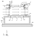
- FIG. 8 shows the flow of wind around the electronic device 1 .
- the flow of running air around the electronic device 1 is indicated by solid arrows. Since the electronic device 1 includes the wind guide member 30 surrounding the ends of the fins 20 on the positive side of the X axis, part of the running wind flowing in the negative direction of the X axis is guided by the wind guide member 30 and After flowing in the direction, it reaches the end of the fin 20 on the positive side of the X axis. In other words, more running wind than in the case of FIG. 7 reaches the ends of the fins 20 on the positive side of the X axis. As a result, the air pressure in the region R1 indicated by the dashed line in FIG. 8, specifically, the region R1 including the ends of the fins 20 on the positive side of the X axis, becomes higher than in FIG. Higher positive pressure.
- the electronic device 1 While flowing between the fins 20 , part of the running wind moves in the Z-axis positive direction and flows along the ends of the fins 20 on the Z-axis positive direction side. Since the electronic device 1 includes the wind guide member 30 surrounding the ends of the fins 20 on the negative side of the X-axis, the running wind flowing along the ends of the fins 20 on the positive side of the Z-axis moves further in the positive Z-axis direction. Then, the air bypasses the wind guide member 30 and flows in the negative direction of the X axis. As a result, as indicated by the dashed line in FIG. 8, the air pressure in the region R2 including the ends of the fins 20 on the negative side of the X axis becomes lower than in the case of FIG. Become.
- the pressure difference between the end of the fin 20 on the positive side of the X-axis and the end of the fin 20 on the negative side of the X-axis becomes larger than in the case of FIG.
- the speed of the running wind flowing between the fins 20 in the negative direction of the X-axis increases, so the cooling performance of the electronic device 1 improves.
- the air pressure in the region R2 becomes positive pressure and the air pressure in the region R1 becomes negative pressure, so that the wind guide member 30 is not provided as shown in FIG.
- the speed of the running wind flowing between the fins 20 in the positive direction of the X-axis is faster, so the cooling performance of the electronic device 1 is improved.
- the size of the air guide member 30 specifically, the area of the main surface 31a of the first member 31 increases, the air pressure in the region R1 increases and the air pressure in the region R2 decreases.
- the cooling performance of the electronic device 1 is improved.
- the size of the air guide member 30 is determined according to the cooling performance required for the electronic device 1 and the vehicle limit range.
- the pressure at the ends of the fins 20 on the positive side of the X-axis and the ends of the fins 20 on the negative side of the X-axis is reduced. the difference increases. As a result, the speed of the running wind flowing between the fins 20 increases, so the cooling performance of the electronic device 1 improves.
- the base 21 can be attached to the upper portion of the housing 10 in the vertical direction using the air guide member 30 as a handle when assembling the electronic device 1 . Since the air guide member 30 is attached to the base 21, even when the air guide member 30 is used as a handle, no stress is generated in the fins 20, and deformation of the fins 20 during assembly of the electronic device 1 is suppressed. becomes possible.
- the present disclosure is not limited to the above embodiments.
- the shape of the air guide member 30 is arbitrary as long as it can increase the pressure difference between the ends of the fins 20 on the positive side of the X-axis and the ends of the fins 20 on the negative side of the X-axis.
- FIG. 9 shows an example of an electronic device 2 having a wind guide member 30 having a shape different from that of the embodiment.
- the air guide member 30 included in the electronic device 2 has a first member 31 and a second member 33 attached to the first member 31 .
- the second member 33 has a main surface 33a that extends away from the center of the fins 20 in the X-axis direction and surrounds the plurality of fins 20 .
- the area of the cross section perpendicular to the first extending direction of the space surrounded by the second member 33 and the base 21 becomes narrower toward the center of the fin 20 in the first extending direction.
- the length of one end near the center of the fin 20 in the first stretching direction around the X axis is shorter than the length around the X-axis of the end.
- the number of air guide members 30 provided in the electronic devices 1 and 2 is arbitrary.
- the electronic devices 1 and 2 may include only the air guide member 30 positioned on the X-axis positive direction side, or only the air guide member 30 positioned on the X-axis negative direction side.
- FIG. 10 shows an electronic device 3 having four air guide members 30 .
- the four air guide members 30 included in the electronic device 3 have the same structure, and are symmetrical with respect to the YZ plane including the center of the fins 20 in the X-axis direction.
- FIG. 11 shows an electronic device 4 having a wind guide member 30 attached to the housing 10 .
- the second member 32 of the air guide member 30 included in the electronic device 4 has a strength that does not change the relative positional relationship between the second member 32 and the housing 10 even when subjected to vibrations during running of the vehicle 100 . It may be attached to the housing 10 .
- the second member 32 is attached to the outer surface of the housing 10 by an attachment method such as fitting, brazing, welding, adhesion using an adhesive, or fastening using a fastening member.
- the first member 31 of the air guide member 30 is in contact with the plurality of fins 20, but the first member 31 may be separated from the plurality of fins 20 as shown in FIG.
- the first member is such that the air pressure at the end of the fins 20 in the X-axis direction can be positive pressure or the air pressure at the end of the fins 20 in the X-axis direction can be negative pressure.
- 31 is preferably provided at a position sufficiently close to the plurality of fins 20 .
- the shapes of the first member 31 and the second members 32, 33 are not limited to the above examples.
- a portion of the first member 31 may have a shape that contacts the base 21 or the housing 10 .
- the first member 31 may be attached to the base 21 or the housing 10 .
- the first member 31 and the second member 32 or 33 may be integrally formed.
- FIG. 13 shows an electronic device 6 having fins arranged side by side in the X-axis direction and the Y-axis direction.
- the electronic device 6 includes 20 fins 20a arranged in the Y-axis direction, and 20 fins 20b arranged in the Y-axis direction and located on the negative X-axis side of the fins 20a.
- the electronic device 6 includes two air guide members 30a provided at both ends of the plurality of fins 20a in the X-axis direction, and two air guide members 30b provided at both ends of the plurality of fins 20b in the X-axis direction.
- the structure of each of the air guide members 30 a and 30 b is the same as that of the air guide member 30 .
- the two air guide members 30a are provided in directions symmetrical with respect to the YZ plane including the center of the fins 20a in the X-axis direction.
- the two air guide members 30b are provided in directions symmetrical with respect to the YZ plane including the center of the fins 20b in the X-axis direction.
- the shape of the fins 20, 20a, 20b is not limited to the above example, and may be, for example, a plate-like member with uneven thickness, a member having a curved surface, or the like.
- the electronic component 11 is not limited to a switching element, and may be any electronic component such as a thyristor, a diode, or the like that is housed inside the housing 10 and generates heat.
- the method by which the electronic device 1-6 cools the electronic component 11 is not limited to cooling using running wind.
- the electronic device 1-6 may cool the electronic component 11 by transferring heat to cooling air supplied from a blower and flowing between the fins 20, 20a, 20b.
- the mounting location of the electronic device 1-6 is not limited to the roof 100a of the vehicle 100.
- electronic device 1 - 6 may be provided under the floor of vehicle 100 .
- the electronic device 1-6 is not limited to railroad vehicles, and can be attached to any moving body such as a trolleybus or a streetcar that generates running wind.
- the electronic devices 1-6 are not limited to in-vehicle devices mounted on railway vehicles, and may be arbitrary electronic devices installed indoors or outdoors. In this case, the electronic device 1-6 may cool the electronic component 11 by transferring heat to the cooling air supplied from the blower and flowing between the fins 20, 20a, and 20b.
Abstract
An electronic device (1) includes: a thermally conductive base (21) in which an electronic component (11) is mounted on a first main surface (21a); and a plurality of fins (20) that are mounted on a second main surface (21b) of the base (21), extends in both a first extension direction and a second extension direction, and dissipate heat transmitted from the electronic component (11) via the base (21) to the surrounding air. The electronic device (1) further includes an air guide member (30) that includes a first member (31) that extends around the plurality of fins (20) and has a main surface (31a) intersecting the first extension direction, and a second member (32) that is mounted on the first member (31) and has a main surface (32a) extending in a direction away from the center of the fins (20) in the first extension direction.
Description
本開示は、電子機器に関する。
This disclosure relates to electronic equipment.
電子機器には、通電時の発熱による電子部品の損傷を防ぐため、発熱体である電子部品に熱的に接続された冷却部を有するものがある。電子機器の一例である、鉄道車両に搭載される電子機器、具体的には、電力変換装置は、電子部品で生じた熱を、冷却部を介して車両の走行によって生じる走行風に放熱することで、電子部品を冷却する。この種の電子機器が備える冷却部の一例として、鉄道車両の床下に取り付けられるヒートシンクが特許文献1に開示されている。特許文献1に開示されているヒートシンクは、ベースと、ベースに取り付けられ、車両の進行方向および鉛直方向に延びる複数のフィンと、を有する。
Some electronic devices have a cooling part that is thermally connected to the electronic parts that are heating elements, in order to prevent damage to the electronic parts due to heat generated when energized. An electronic device mounted on a railway vehicle, which is an example of an electronic device, more specifically, a power converter, dissipates heat generated by electronic components into the running wind generated by the running of the vehicle via a cooling unit. to cool the electronic components. As an example of a cooling unit included in this type of electronic device, Patent Document 1 discloses a heat sink attached to the underfloor of a railway vehicle. The heat sink disclosed in Patent Literature 1 has a base and a plurality of fins attached to the base and extending in the traveling direction and vertical direction of the vehicle.
特許文献1に開示されるヒートシンクは、走行風を整流するために、車両の進行方向の端部において主面がベースとの間に複数のフィンを挟んで位置する平板状の整風部と、整風部とベースに連結され、複数のフィンの端部を覆う板状の補強部と、を備える。整風部と補強部が設けられることで、複数のフィンの進行方向の端部が、主面が進行方向に沿う平板状の部材で覆われているため、進行方向の端部からフィンに流入する空気の量が低下し、冷却性能が低下してしまう。この課題は、車両に搭載される電子機器に限られず、外部から供給される空気にフィンから熱を伝達することで電子部品を冷却する構造を有する電子機器において起こり得る。
The heat sink disclosed in Patent Literature 1 includes a flat plate-like air regulating portion having a plurality of fins interposed between a main surface and a base at an end portion in the traveling direction of the vehicle, and an air regulating portion, in order to rectify the running wind. and a plate-shaped reinforcing part connected to the part and the base and covering the ends of the plurality of fins. By providing the air regulating portion and the reinforcing portion, the ends of the plurality of fins in the direction of travel are covered with a flat plate-shaped member whose main surface is along the direction of travel, so air flows into the fins from the ends in the direction of travel. The amount of air is reduced and the cooling performance is reduced. This problem is not limited to electronic devices mounted on a vehicle, but may occur in electronic devices having a structure that cools electronic components by transferring heat from fins to air supplied from the outside.
本開示は上述の事情に鑑みてなされたものであり、冷却性能の高い電子機器を提供することを目的とする。
The present disclosure has been made in view of the circumstances described above, and aims to provide an electronic device with high cooling performance.
上記目的を達成するために、本開示の電子機器は、伝熱性のベースと、複数のフィンと、1つまたは複数の導風部材と、を備える。ベースの第1主面に、電子部品が取り付けられる。複数のフィンは、第1主面の反対に位置する第2主面に互いに間隔を空けて取り付けられ、第2主面に沿う方向である第1延伸方向および第2主面から離れる方向である第2延伸方向の両方向に延び、ベースを介して電子部品から伝達された熱を、周囲を流れる空気に放熱する。導風部材は、複数のフィンの周りに延在し、第1延伸方向に交差する主面を有する第1部材と、第1部材に取り付けられ、フィンの第1延伸方向の中心から離れる方向に延びる主面を有する第2部材と、を有する。
To achieve the above object, the electronic device of the present disclosure includes a heat conductive base, a plurality of fins, and one or a plurality of air guide members. An electronic component is attached to the first major surface of the base. The plurality of fins are attached to a second main surface opposite to the first main surface and are spaced apart from each other, and have a first extending direction along the second main surface and a direction away from the second main surface. Extending in both directions of the second extending direction, the heat transferred from the electronic component via the base is radiated to the air flowing around. The air guide member includes a first member extending around the plurality of fins and having a main surface intersecting the first extending direction, and attached to the first member and extending in a direction away from the center of the first extending direction of the fins. a second member having an extending major surface.
本開示に係る電子機器は、第1部材と第2部材とを有する導風部材を備えることで、複数のフィンの端部が、主面がフィンの延伸方向に沿う平板状の部材で覆われている場合と比べて、フィンの風上側と風下側の圧力差を増大させ、フィンの周囲を流れる空気の流速を速くすることができる。この結果、冷却性能の高い電子機器が得られる。
The electronic device according to the present disclosure includes the air guide member having the first member and the second member, so that the ends of the plurality of fins are covered with a flat member having a main surface along the extending direction of the fins. The pressure difference between the windward side and the leeward side of the fins can be increased, and the flow velocity of the air flowing around the fins can be increased compared to the case where the fins are provided. As a result, an electronic device with high cooling performance can be obtained.
以下、本開示の実施の形態に係る電子機器について図面を参照して詳細に説明する。なお図中、同一または同等の部分には同一の符号を付す。
Electronic devices according to embodiments of the present disclosure will be described in detail below with reference to the drawings. In the drawings, the same reference numerals are given to the same or equivalent parts.
電子機器の一例に、鉄道車両の屋根に搭載される車載機器がある。鉄道車両の走行によって生じる鉄道車両の進行方向と反対方向に向かう空気の流れである走行風を利用して電子部品を冷却する車載機器を例にして、実施の形態に係る電子機器1について説明する。
An example of an electronic device is an in-vehicle device mounted on the roof of a railroad vehicle. An electronic device 1 according to an embodiment will be described by taking as an example an in-vehicle device that cools an electronic component by using running wind, which is an air flow generated by running of a railroad car and directed in a direction opposite to the traveling direction of the railroad car. .
図1に示す電子機器1は、例えば鉄道車両である車両100の屋根100aに設けられる。図1および図1におけるII-II線での矢視断面図である図2に示すように、電子機器1は、電子部品11が第1主面21aに取り付けられる伝熱性のベース21と、ベース21の第2主面21bに取り付けられ、ベース21を介して電子部品11から伝達された熱を周囲の空気に放熱する複数のフィン20と、複数のフィン20の周りに延在する1つまたは複数の導風部材30と、を備える。
The electronic device 1 shown in FIG. 1 is installed on the roof 100a of a vehicle 100, which is, for example, a railroad vehicle. As shown in FIG. 1 and FIG. 2, which is a cross-sectional view taken along line II-II in FIG. a plurality of fins 20 attached to the second main surface 21b of the base 21 and dissipating heat transferred from the electronic component 11 via the base 21 to the surrounding air; and a plurality of air guide members 30 .
電子機器1はさらに、屋根100aに設置され、電子部品11を収容する筐体10を備えることが好ましい。この場合、ベース21は、筐体10の開口10aを塞いだ状態で筐体10に取り付けられればよい。
It is preferable that the electronic device 1 further includes a housing 10 installed on the roof 100 a and containing the electronic components 11 . In this case, the base 21 may be attached to the housing 10 while closing the opening 10a of the housing 10 .
図1および図2において、Z軸は、車両100が水平に位置している状態で、鉛直方向を示す。X軸は、車両100の進行方向を示す。Y軸は、車両100の幅方向を示す。X軸、Y軸、およびZ軸は互いに直交する。後続の図においても同様である。
In FIGS. 1 and 2, the Z axis indicates the vertical direction with the vehicle 100 positioned horizontally. The X-axis indicates the traveling direction of the vehicle 100 . The Y-axis indicates the width direction of vehicle 100 . The X-, Y-, and Z-axes are orthogonal to each other. The same applies to subsequent figures.
筐体10は屋根100aの鉛直方向上部に取り付けられる。筐体10は、鉄道車両の予想される最大振動を受けても変形しない程度の剛性と強度を有する。例えば、筐体10は、鉄、アルミニウム等の金属部材で形成される。筐体10の鉛直方向上部に開口10aが形成される。
The housing 10 is attached to the upper part of the roof 100a in the vertical direction. The housing 10 has such rigidity and strength that it does not deform even when subjected to the maximum expected vibration of the railway vehicle. For example, the housing 10 is made of a metal member such as iron or aluminum. An opening 10a is formed in the upper portion of the housing 10 in the vertical direction.
ベース21は、開口10aを塞いだ状態で筐体10に取り付けられる。実施の形態では、ベース21は、熱伝導率の高い部材、例えば、鉄、アルミニウム等の金属部材で形成され、開口10aを塞いだ状態で筐体10の外面に取り付けられる平板状の部材である。ベース21の第1主面21aに、発熱する電子部品11、例えば、電源から供給される電力を負荷装置に供給するための電力に変換する電力変換部が有するスイッチング素子が取り付けられる。第1主面21aの反対に位置する第2主面21bに複数のフィン20が取り付けられる。例えば、第2主面21bに形成された溝にフィン20の端部が挿入される。車両100が水平に位置している状態で、第1主面21aおよび第2主面21bは、水平になる。
The base 21 is attached to the housing 10 while closing the opening 10a. In the embodiment, the base 21 is a plate-shaped member made of a member having a high thermal conductivity, such as a metal member such as iron or aluminum, and is attached to the outer surface of the housing 10 while closing the opening 10a. . On the first main surface 21a of the base 21, a heat-generating electronic component 11, for example, a switching element included in a power conversion unit that converts power supplied from a power source into power for supplying a load device is attached. A plurality of fins 20 are attached to a second major surface 21b located opposite to the first major surface 21a. For example, the ends of the fins 20 are inserted into grooves formed in the second main surface 21b. With the vehicle 100 positioned horizontally, the first main surface 21a and the second main surface 21b are horizontal.
ベース21は、車両100の走行時の振動を受けても、ベース21と筐体10との相対的な位置関係が変化しない程度の強度で筐体10に取り付けられればよい。具体的には、ベース21は、嵌合、ろう付け、溶接、接着剤を用いた接着、締結部材を用いた締結等の取り付け方法で筐体10の外面に取り付けられる。
The base 21 may be attached to the housing 10 with enough strength that the relative positional relationship between the base 21 and the housing 10 does not change even if the vehicle 100 is subjected to vibrations while the vehicle 100 is running. Specifically, the base 21 is attached to the outer surface of the housing 10 by an attachment method such as fitting, brazing, welding, adhesion using an adhesive, or fastening using a fastening member.
複数のフィン20は、互いに間隔を空けて第2主面21bに取り付けられる。実施の形態では、20個のフィン20が、Y軸方向に互いに間隔を空けて並べられ、第2主面21bに取り付けられる。複数のフィン20は、車両100の走行時の振動を受けても、ベース21と各フィン20との相対的な位置関係が変化しない程度の強度でベース21に取り付けられればよい。具体的には、各フィン20は、嵌合、ろう付け、溶接、接着剤を用いた接着、締結部材を用いた締結等の取り付け方法でベース21の第2主面21bに取り付けられる。
A plurality of fins 20 are attached to the second main surface 21b at intervals. In the embodiment, twenty fins 20 are spaced apart from each other in the Y-axis direction and attached to the second major surface 21b. The plurality of fins 20 may be attached to the base 21 with such strength that the relative positional relationship between the base 21 and each fin 20 does not change even if the vehicle 100 is subjected to vibrations during travel. Specifically, each fin 20 is attached to the second main surface 21b of the base 21 by an attachment method such as fitting, brazing, welding, adhesion using an adhesive, or fastening using a fastening member.
各フィン20は、第2主面21bに沿う方向である第1延伸方向および第2主面21bから離れる方向である第2延伸方向の両方向に延びる。実施の形態では、第1延伸方向は、X軸に平行であり、第2延伸方向は、Z軸に平行である。換言すれば、フィン20は、平板状の部材で形成され、主面がY軸に直交する向きで第2主面21bに取り付けられる。
Each fin 20 extends in both the first extension direction along the second main surface 21b and the second extension direction away from the second main surface 21b. In embodiments, the first draw direction is parallel to the X-axis and the second draw direction is parallel to the Z-axis. In other words, the fin 20 is formed of a flat member and attached to the second main surface 21b with the main surface perpendicular to the Y-axis.
各フィン20は、ベース21を介して電子部品11から伝達された熱を、周囲の空気に放熱する。例えば、車両100の走行時には、フィン20から、フィン20に沿って流れる走行風に熱が伝達される。各フィン20は、熱伝導率の高い材料、例えば、銅、アルミニウム等の金属で形成される。
Each fin 20 dissipates heat transferred from the electronic component 11 through the base 21 to the surrounding air. For example, when the vehicle 100 is running, heat is transferred from the fins 20 to the running wind flowing along the fins 20 . Each fin 20 is made of a material with high thermal conductivity, such as a metal such as copper or aluminum.
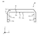
実施の形態では、図3に示すように、電子機器1は、複数のフィン20のX軸方向の両端に設けられる2つの導風部材30を備える。2つの導風部材30の一方は、フィン20のそれぞれの第1延伸方向の一方の端部、例えば、フィン20のそれぞれのX軸正方向側の端部の周りに延在する。詳細には、2つの導風部材30の一方は、フィン20のそれぞれのX軸正方向側の端部に隣接した位置で、X軸に対する周方向に延在する。2つの導風部材30の他方は、フィン20のそれぞれの第1延伸方向の他方の端部、例えば、フィン20のそれぞれのX軸負方向側の端部の周りに延在する。詳細には、2つの導風部材30の他方は、フィン20のそれぞれのX軸負方向側の端部に隣接した位置で、X軸に対する周方向に延在する。2つの導風部材30の構造は互いに同じであり、フィン20のX軸方向における中心を含むYZ平面に対して対称となる向きで設けられる。導風部材30は、走行風をフィン20に導くことが可能な程度にフィン20に隣接した位置に設けられればよい。
In the embodiment, as shown in FIG. 3, the electronic device 1 includes two air guide members 30 provided at both ends of the plurality of fins 20 in the X-axis direction. One of the two air guide members 30 extends around one end of each of the fins 20 in the first extending direction, for example, the end of each of the fins 20 on the X-axis positive direction side. Specifically, one of the two air guide members 30 extends in the circumferential direction with respect to the X axis at a position adjacent to the end of each fin 20 on the positive side of the X axis. The other of the two air guide members 30 extends around the other end of each of the fins 20 in the first extending direction, for example, the end of each of the fins 20 on the X-axis negative direction side. Specifically, the other of the two air guide members 30 extends in the circumferential direction with respect to the X axis at a position adjacent to the end of each fin 20 on the negative side of the X axis. The two air guide members 30 have the same structure and are symmetrical with respect to the YZ plane including the center of the fin 20 in the X-axis direction. The wind guide member 30 may be provided at a position adjacent to the fins 20 to the extent that the running wind can be guided to the fins 20 .
各導風部材30は、車両100の走行時の振動を受けても、ベース21と各導風部材30との相対的な位置関係が変化しない程度の強度でベース21に取り付けられればよい。具体的には、各導風部材30は、嵌合、ろう付け、溶接、接着剤を用いた接着、締結部材を用いた締結等の取り付け方法でベース21の第2主面21bに取り付けられる。
Each air guide member 30 should be attached to the base 21 with enough strength that the relative positional relationship between the base 21 and each air guide member 30 does not change even if the vehicle 100 is subjected to vibrations while the vehicle 100 is running. Specifically, each air guide member 30 is attached to the second main surface 21b of the base 21 by an attachment method such as fitting, brazing, welding, adhesion using an adhesive, or fastening using a fastening member.
各導風部材30は、複数のフィン20周りに延在する第1部材31と、第1部材31に取り付けられ、フィン20の第1延伸方向の中心から離れる方向に延びる主面を有する第2部材32と、を有する。
Each air guide member 30 includes a first member 31 extending around the plurality of fins 20 and a second main surface attached to the first member 31 and extending away from the center of the fins 20 in the first extending direction. a member 32;
図4から図6に示すように、第1部材31は、X軸に対する周方向に延在する板状の部材である。詳細には、第1部材31は、第1延伸方向に交差する主面31aと、複数のフィン20に向く側面31bと、を有する。図4において、筐体10の記載が省略されている。実施の形態では、第1部材31は、複数のフィン20のベース21から遠い端部、換言すれば、複数のフィン30のZ軸正方向側の端部に当接する。各フィン20の端部のY軸方向のずれを抑制するために、第1部材31には、それぞれがフィン20のZ軸正方向側の端部と嵌合する複数のスリット31cが形成される。
As shown in FIGS. 4 to 6, the first member 31 is a plate-shaped member extending in the circumferential direction with respect to the X-axis. Specifically, the first member 31 has a main surface 31 a that intersects the first extending direction and side surfaces 31 b facing the plurality of fins 20 . In FIG. 4, the illustration of the housing 10 is omitted. In the embodiment, the first member 31 contacts ends of the plurality of fins 20 far from the base 21 , in other words, ends of the plurality of fins 30 on the Z-axis positive direction side. In order to suppress the displacement of the ends of the fins 20 in the Y-axis direction, the first member 31 is formed with a plurality of slits 31c each fitted with the end of the fin 20 on the Z-axis positive direction side. .
例えば、フィン20よりZ軸正方向側に位置する第1部材31の一部のZ軸方向の長さは、フィン20のZ軸方向の長さの1/5以上、かつ、1/3以下の長さである。同様に、フィン20にY軸方向に隣接する第1部材31の一部のY軸方向の長さは、フィン20のZ軸方向の長さの1/5以上、かつ、1/3以下の長さである。上述のように第1部材31の一部のZ軸方向の長さおよび第1部材31の他の一部のY軸方向の長さを定めることで、第2部材32とフィン20との間隔がフィン20のZ軸方向の長さの1/3以下とみなせる長さとなり、第1部材31および第2部材32によって、走行風をフィン20の端部に導くことが可能となる。
For example, the length in the Z-axis direction of the portion of the first member 31 located on the Z-axis positive side of the fins 20 is ⅕ or more and ⅓ or less of the length of the fins 20 in the Z-axis direction. is the length of Similarly, the length in the Y-axis direction of a portion of the first member 31 adjacent to the fin 20 in the Y-axis direction is ⅕ or more and ⅓ or less of the length of the fin 20 in the Z-axis direction. length. By determining the length in the Z-axis direction of a part of the first member 31 and the length in the Y-axis direction of another part of the first member 31 as described above, the distance between the second member 32 and the fins 20 is is equal to or less than 1/3 of the length of the fins 20 in the Z-axis direction, and the first member 31 and the second member 32 can guide the running wind to the ends of the fins 20 .
ベース21を介して電子部品11から熱を伝達されるフィン20およびフィン20に嵌合し、フィン20から熱を伝達される導風部材30の変形によって、フィン20または導風部材30の損傷を防ぐことが可能な程度に、導風部材30は、フィン20の熱膨張係数に十分に近い熱膨張係数を有する部材で形成されることが好ましい。例えば、導風部材30は、フィン20と同じ部材で形成されることが好ましい。
Deformation of the fins 20 to which heat is transferred from the electronic component 11 via the base 21 and the air guide member 30 fitted to the fins 20 to which heat is transferred from the fins 20 may damage the fins 20 or the air guide member 30. The air guide member 30 is preferably made of a member having a coefficient of thermal expansion sufficiently close to that of the fins 20 to the extent that it can be prevented. For example, the air guide member 30 is preferably made of the same material as the fins 20 .
図2に示すように、第1部材31は、複数のフィン20の配列方向において両端に位置するフィン20の一部、換言すれば、Y軸方向両端に位置するフィン20のZ軸正方向側の端部よりベース21に近い部分に、空隙22を空けて隣接する。この結果、Y軸方向両端に位置するフィン20から、空隙22を通る走行風に熱を伝達することができ、電子機器1の冷却性能が向上する。
As shown in FIG. 2, the first member 31 is a part of the fins 20 located at both ends in the arrangement direction of the plurality of fins 20, in other words, the positive Z-axis side of the fins 20 located at both ends in the Y-axis direction. is adjacent to a portion closer to the base 21 than the end of the base 21 with a gap 22 therebetween. As a result, the heat can be transferred from the fins 20 located at both ends in the Y-axis direction to the traveling wind passing through the gaps 22, and the cooling performance of the electronic device 1 is improved.
図4から図6に示すように、第2部材32は、X軸に対する周方向に延在する板状の部材であって、第1部材31に取り付けられる。第2部材32は、車両100の走行時の振動を受けても、第1部材31と第2部材32との相対的な位置関係が変化しない程度の強度で第1部材31に取り付けられればよい。具体的には、第2部材32は、嵌合、ろう付け、溶接、接着剤を用いた接着、締結部材を用いた締結等の取り付け方法で第1部材31の主面31aに取り付けられる。
As shown in FIGS. 4 to 6, the second member 32 is a plate-like member extending in the circumferential direction with respect to the X-axis and attached to the first member 31. As shown in FIG. The second member 32 only needs to be attached to the first member 31 with such strength that the relative positional relationship between the first member 31 and the second member 32 does not change even if the vehicle 100 is subjected to vibration during running. . Specifically, the second member 32 is attached to the main surface 31a of the first member 31 by an attachment method such as fitting, brazing, welding, adhesion using an adhesive, or fastening using a fastening member.
第2部材32は、フィン20の第1延伸方向の中心、換言すれば、フィン20のX軸方向の中心から離れる方向に延びる主面32aを有する。主面32aは、X軸に対する周方向に延在して複数のフィン20を囲む。実施の形態では、主面32aは、第1延伸方向に延びる。
The second member 32 has a main surface 32a extending away from the center of the fins 20 in the first extending direction, in other words, the center of the fins 20 in the X-axis direction. The main surface 32 a surrounds the plurality of fins 20 extending in the circumferential direction with respect to the X-axis. In an embodiment, major surface 32a extends in the first stretching direction.
第2部材32は、ベース21に取り付けられる。第2部材32は、車両100の走行時の振動を受けても、第2部材32とベース21との相対的な位置関係が変化しない程度の強度でベース21に取り付けられればよい。具体的には、第2部材32は、嵌合、ろう付け、溶接、接着剤を用いた接着、締結部材を用いた締結等の取り付け方法でベース21の第2主面21bに取り付けられる。
The second member 32 is attached to the base 21. The second member 32 may be attached to the base 21 with such strength that the relative positional relationship between the second member 32 and the base 21 does not change even if the vehicle 100 is subjected to vibration during running. Specifically, the second member 32 is attached to the second main surface 21b of the base 21 by an attachment method such as fitting, brazing, welding, adhesion using an adhesive, or fastening using a fastening member.
第2部材32がベース21に取り付けられることで、ベース21を介して電子部品11から第2部材32に伝達された熱は、第2部材32からの熱放射および第2部材32から第2部材32の周囲の空気への熱伝達によって放熱される。さらに、ベース21および第2部材32を介して電子部品11から第1部材31に伝達された熱は、第1部材31からの熱放射および第1部材31から第1部材31の周囲の空気への熱伝達によって放熱される。上述のように放熱が行われることで、電子部品11が冷却される。
Since the second member 32 is attached to the base 21 , the heat transferred from the electronic component 11 to the second member 32 via the base 21 is transferred from the second member 32 to the heat radiation from the second member 32 . Heat is dissipated by heat transfer to the surrounding air at 32 . Furthermore, the heat transferred from the electronic component 11 to the first member 31 via the base 21 and the second member 32 is transferred from the first member 31 to the heat radiation from the first member 31 and from the first member 31 to the air around the first member 31. heat is dissipated by the heat transfer of The electronic component 11 is cooled by heat radiation as described above.
上記構成を有する電子機器1の周囲における走行風の流れについて、電子機器1が搭載される車両100がX軸正方向に進行する場合を例にして、以下に説明する。比較例として、導風部材30を備えない電子機器9の周囲における走行風の流れを図7に示す。図7において、電子機器9の周囲における走行風の流れを実線の矢印で示す。
The flow of wind around the electronic device 1 having the above configuration will be described below, taking as an example the case where the vehicle 100 on which the electronic device 1 is mounted travels in the positive direction of the X axis. As a comparative example, FIG. 7 shows the flow of running air around an electronic device 9 that does not have the air guide member 30 . In FIG. 7 , the flow of running air around the electronic device 9 is indicated by solid-line arrows.
電子機器9の構成は、導風部材30を備えない点を除いて、電子機器1と同様である。詳細には、電子機器9は、車両100の屋根100aに取り付けられる筐体90と、筐体90の開口90aを塞ぐ向きで筐体90に取り付けられるベース91と、ベース91の第1主面91aに取り付けられる電子部品92と、ベース91の第2主面91bに取り付けられる複数のフィン93と、を備える。
The configuration of the electronic device 9 is the same as that of the electronic device 1 except that the air guide member 30 is not provided. Specifically, the electronic device 9 includes a housing 90 attached to the roof 100a of the vehicle 100, a base 91 mounted to the housing 90 in a direction to close the opening 90a of the housing 90, and a first main surface 91a of the base 91. and a plurality of fins 93 attached to the second major surface 91 b of the base 91 .
車両100の進行方向前方から進行方向後方に向かって流れる走行風、換言すれば、X軸負方向に流れる走行風は、フィン93に沿って流れる。フィン93の間を流れている間に一部の走行風はZ軸正方向に移動し、フィン93のZ軸正方向側の端部に沿って流れる。
The traveling wind that flows from the front to the rear in the traveling direction of the vehicle 100 , in other words, the traveling wind that flows in the negative direction of the X axis flows along the fins 93 . While flowing between the fins 93 , part of the running wind moves in the Z-axis positive direction and flows along the ends of the fins 93 on the Z-axis positive direction side.
電子機器1の周囲における走行風の流れを図8に示す。図8において、電子機器1の周囲における走行風の流れを実線の矢印で示す。電子機器1がフィン20のX軸正方向側の端部を囲む導風部材30を備えるため、X軸負方向に流れる走行風の一部は、導風部材30によって導風され、Z軸負方向側に流れてからフィン20のX軸正方向側の端部に到達する。換言すれば、図7の場合よりも多い走行風がフィン20のX軸正方向側の端部に到達する。この結果、図8において一点鎖線で示す領域R1、具体的には、フィン20のX軸正方向側の端部を含む領域R1における空気の圧力は、図7の場合よりも高くなり、大気圧より高い正圧となる。
FIG. 8 shows the flow of wind around the electronic device 1 . In FIG. 8 , the flow of running air around the electronic device 1 is indicated by solid arrows. Since the electronic device 1 includes the wind guide member 30 surrounding the ends of the fins 20 on the positive side of the X axis, part of the running wind flowing in the negative direction of the X axis is guided by the wind guide member 30 and After flowing in the direction, it reaches the end of the fin 20 on the positive side of the X axis. In other words, more running wind than in the case of FIG. 7 reaches the ends of the fins 20 on the positive side of the X axis. As a result, the air pressure in the region R1 indicated by the dashed line in FIG. 8, specifically, the region R1 including the ends of the fins 20 on the positive side of the X axis, becomes higher than in FIG. Higher positive pressure.
フィン20の間を流れている間に一部の走行風はZ軸正方向に移動し、フィン20のZ軸正方向側の端部に沿って流れる。電子機器1がフィン20のX軸負方向側の端部を囲む導風部材30を備えるため、フィン20のZ軸正方向側の端部に沿って流れる走行風はさらにZ軸正方向に移動し、導風部材30を迂回してX軸負方向に流れる。この結果、図8において一点鎖線で示すように、フィン20のX軸負方向側の端部を含む領域R2における空気の圧力は、図7の場合よりも低くなり、大気圧より低い負圧となる。電子機器1において、フィン20のX軸正方向側の端部とフィン20のX軸負方向側の端部の気圧差が図7の場合よりも大きくなる。この結果、フィン20の間をX軸負方向に流れる走行風の速さが速くなるため、電子機器1の冷却性能が向上する。
While flowing between the fins 20 , part of the running wind moves in the Z-axis positive direction and flows along the ends of the fins 20 on the Z-axis positive direction side. Since the electronic device 1 includes the wind guide member 30 surrounding the ends of the fins 20 on the negative side of the X-axis, the running wind flowing along the ends of the fins 20 on the positive side of the Z-axis moves further in the positive Z-axis direction. Then, the air bypasses the wind guide member 30 and flows in the negative direction of the X axis. As a result, as indicated by the dashed line in FIG. 8, the air pressure in the region R2 including the ends of the fins 20 on the negative side of the X axis becomes lower than in the case of FIG. Become. In the electronic device 1, the pressure difference between the end of the fin 20 on the positive side of the X-axis and the end of the fin 20 on the negative side of the X-axis becomes larger than in the case of FIG. As a result, the speed of the running wind flowing between the fins 20 in the negative direction of the X-axis increases, so the cooling performance of the electronic device 1 improves.
車両100がX軸負方向に進行する場合は、領域R2における空気の圧力が正圧となり、領域R1における空気の圧力が負圧となることで、図7のように導風部材30を備えない電子機器9と比べて、フィン20の間をX軸正方向に流れる走行風の速さが速くなるため、電子機器1の冷却性能が向上する。
When the vehicle 100 travels in the negative direction of the X axis, the air pressure in the region R2 becomes positive pressure and the air pressure in the region R1 becomes negative pressure, so that the wind guide member 30 is not provided as shown in FIG. Compared to the electronic device 9, the speed of the running wind flowing between the fins 20 in the positive direction of the X-axis is faster, so the cooling performance of the electronic device 1 is improved.
導風部材30の大きさ、具体的には、第1部材31の主面31aの面積が大きくなると、領域R1における空気の圧力がより高くなり、領域R2における空気の圧力がより低くなるため、電子機器1の冷却性能が向上する。電子機器1の冷却性能を高めるためには、車両100の最大寸法を示す車両限界の範囲で導風部材30を大きくすることが好ましい。車両限界の範囲で導風部材30を大きくするためには、フィン20を小さくする必要があるが、フィン20を小さくすると冷却性能が低下してしまう。そこで、導風部材30の大きさは、電子機器1に求められる冷却性能および車両限界の範囲に応じて定められることが好ましい。
As the size of the air guide member 30, specifically, the area of the main surface 31a of the first member 31 increases, the air pressure in the region R1 increases and the air pressure in the region R2 decreases. The cooling performance of the electronic device 1 is improved. In order to improve the cooling performance of the electronic device 1 , it is preferable to increase the size of the air guide member 30 within the range of the vehicle limit indicating the maximum dimension of the vehicle 100 . In order to increase the size of the air guide member 30 within the vehicle limit, it is necessary to reduce the size of the fins 20. However, if the size of the fins 20 is reduced, the cooling performance will deteriorate. Therefore, it is preferable that the size of the air guide member 30 is determined according to the cooling performance required for the electronic device 1 and the vehicle limit range.
以上説明した通り、実施の形態に係る電子機器1において、導風部材30が設けられることで、フィン20のX軸正方向側の端部とフィン20のX軸負方向側の端部の気圧差が大きくなる。この結果、フィン20の間を流れる走行風の速さが速くなるため、電子機器1の冷却性能が向上する。
As described above, in the electronic device 1 according to the embodiment, by providing the wind guide member 30, the pressure at the ends of the fins 20 on the positive side of the X-axis and the ends of the fins 20 on the negative side of the X-axis is reduced. the difference increases. As a result, the speed of the running wind flowing between the fins 20 increases, so the cooling performance of the electronic device 1 improves.
導風部材30がベース21に取り付けられているため、電子機器1を組み立てる際に、導風部材30を持ち手として用いてベース21を筐体10の鉛直方向上部に取り付けることが可能となる。導風部材30はベース21に取り付けられているため、導風部材30を持ち手として用いた場合でも、フィン20に応力が生じず、電子機器1の組み立て時におけるフィン20の変形を抑制することが可能となる。
Since the air guide member 30 is attached to the base 21 , the base 21 can be attached to the upper portion of the housing 10 in the vertical direction using the air guide member 30 as a handle when assembling the electronic device 1 . Since the air guide member 30 is attached to the base 21, even when the air guide member 30 is used as a handle, no stress is generated in the fins 20, and deformation of the fins 20 during assembly of the electronic device 1 is suppressed. becomes possible.
本開示は、上述の実施の形態に限られない。導風部材30の形状は、フィン20のX軸正方向側の端部とフィン20のX軸負方向側の端部の気圧差を大きくすることが可能な形状であれば、任意である。実施の形態と異なる形状の導風部材30を備える電子機器2の例を図9に示す。電子機器2が備える導風部材30は、第1部材31と、第1部材31に取り付けられる第2部材33と、を有する。
The present disclosure is not limited to the above embodiments. The shape of the air guide member 30 is arbitrary as long as it can increase the pressure difference between the ends of the fins 20 on the positive side of the X-axis and the ends of the fins 20 on the negative side of the X-axis. FIG. 9 shows an example of an electronic device 2 having a wind guide member 30 having a shape different from that of the embodiment. The air guide member 30 included in the electronic device 2 has a first member 31 and a second member 33 attached to the first member 31 .
第2部材33は、フィン20のX軸方向の中心から離れる方向に延びて複数のフィン20を囲む主面33aを有する。第2部材33とベース21とで囲まれる空間の第1延伸方向に直交する断面の面積は、フィン20の第1延伸方向の中心に近づくにつれて狭くなる。換言すれば、第2部材33の第1延伸方向の両端部の内、フィン20の第1延伸方向の中心に近い一方の端部のX軸周りの長さは、両端部の内、他方の端部のX軸周りの長さより短い。上記形状を有する導風部材30を設けることで、よりスムーズに走行風がフィン20の端部に到達する。
The second member 33 has a main surface 33a that extends away from the center of the fins 20 in the X-axis direction and surrounds the plurality of fins 20 . The area of the cross section perpendicular to the first extending direction of the space surrounded by the second member 33 and the base 21 becomes narrower toward the center of the fin 20 in the first extending direction. In other words, among both ends of the second member 33 in the first stretching direction, the length of one end near the center of the fin 20 in the first stretching direction around the X axis is shorter than the length around the X-axis of the end. By providing the wind guide member 30 having the above shape, the running wind reaches the end of the fin 20 more smoothly.
電子機器1,2が備える導風部材30の個数は、任意である。一例として、電子機器1,2は、X軸正方向側に位置する導風部材30のみ、または、X軸負方向側に位置する導風部材30のみを備えてもよい。他の一例として、4つの導風部材30を備える電子機器3を図10に示す。電子機器3が備える4つの導風部材30の構造は互いに同じであり、フィン20のX軸方向における中心を含むYZ平面に対して対称となる向きで設けられる。
The number of air guide members 30 provided in the electronic devices 1 and 2 is arbitrary. As an example, the electronic devices 1 and 2 may include only the air guide member 30 positioned on the X-axis positive direction side, or only the air guide member 30 positioned on the X-axis negative direction side. As another example, FIG. 10 shows an electronic device 3 having four air guide members 30 . The four air guide members 30 included in the electronic device 3 have the same structure, and are symmetrical with respect to the YZ plane including the center of the fins 20 in the X-axis direction.
実施の形態では、導風部材30はベース21に取り付けられているが、導風部材30の固定方法は、上述の例に限られない。一例として、筐体10に取り付けられる導風部材30を備える電子機器4を図11に示す。電子機器4が備える導風部材30の第2部材32は、車両100の走行時の振動を受けても、第2部材32と筐体10との相対的な位置関係が変化しない程度の強度で筐体10に取り付けられればよい。具体的には、第2部材32は、嵌合、ろう付け、溶接、接着剤を用いた接着、締結部材を用いた締結等の取り付け方法で筐体10の外面に取り付けられる。
Although the air guide member 30 is attached to the base 21 in the embodiment, the fixing method of the air guide member 30 is not limited to the above example. As an example, FIG. 11 shows an electronic device 4 having a wind guide member 30 attached to the housing 10 . The second member 32 of the air guide member 30 included in the electronic device 4 has a strength that does not change the relative positional relationship between the second member 32 and the housing 10 even when subjected to vibrations during running of the vehicle 100 . It may be attached to the housing 10 . Specifically, the second member 32 is attached to the outer surface of the housing 10 by an attachment method such as fitting, brazing, welding, adhesion using an adhesive, or fastening using a fastening member.
実施の形態では、導風部材30の第1部材31が複数のフィン20に当接しているが、第1部材31は図12に示すように、複数のフィン20から離隔していてもよい。図12に示す電子機器5が備える導風部材30の第1部材31は、複数のフィン20から離隔し、かつ、複数のフィン20に隣接している位置で、複数のフィン20の周りに延在する。フィン20のX軸方向端部での空気の圧力を正圧にすること、または、フィン20のX軸方向端部での空気の圧力を負圧にすることが可能な程度に、第1部材31は、複数のフィン20に十分に近い位置に設けられることが好ましい。
In the embodiment, the first member 31 of the air guide member 30 is in contact with the plurality of fins 20, but the first member 31 may be separated from the plurality of fins 20 as shown in FIG. The first member 31 of the air guide member 30 included in the electronic device 5 shown in FIG. exist. The first member is such that the air pressure at the end of the fins 20 in the X-axis direction can be positive pressure or the air pressure at the end of the fins 20 in the X-axis direction can be negative pressure. 31 is preferably provided at a position sufficiently close to the plurality of fins 20 .
第1部材31および第2部材32,33の形状は、上述の例に限られない。一例として、第1部材31の一部がベース21または筐体10に当接する形状を有しても良い。この場合、第1部材31がベース21または筐体10に取り付けられてもよい。第1部材31と第2部材32または第2部材33とは、一体に形成されてもよい。
The shapes of the first member 31 and the second members 32, 33 are not limited to the above examples. As an example, a portion of the first member 31 may have a shape that contacts the base 21 or the housing 10 . In this case, the first member 31 may be attached to the base 21 or the housing 10 . The first member 31 and the second member 32 or 33 may be integrally formed.
電子機器1-5が備えるフィン20の個数、配置位置、形状等は、フィン20の間を通る空気に熱を伝達することで電子部品11を冷却することができれば、任意である。一例として、X軸方向およびY軸方向に並べて設けられるフィンを備える電子機器6を図13に示す。電子機器6は、Y軸方向に並べられる20個のフィン20aと、フィン20aよりX軸負方向側に位置し、Y軸方向に並べられる20個のフィン20bと、を備える。
The number, arrangement position, shape, etc. of the fins 20 included in the electronic device 1-5 are arbitrary as long as the electronic component 11 can be cooled by transferring heat to the air passing between the fins 20. As an example, FIG. 13 shows an electronic device 6 having fins arranged side by side in the X-axis direction and the Y-axis direction. The electronic device 6 includes 20 fins 20a arranged in the Y-axis direction, and 20 fins 20b arranged in the Y-axis direction and located on the negative X-axis side of the fins 20a.
電子機器6は、複数のフィン20aのX軸方向の両端に設けられる2つの導風部材30aと、複数のフィン20bのX軸方向の両端に設けられる2つの導風部材30bと、を備える。導風部材30a,30bのそれぞれの構造は、導風部材30と同じである。2つの導風部材30aは、フィン20aのX軸方向における中心を含むYZ平面に対して対称となる向きで設けられる。2つの導風部材30bは、フィン20bのX軸方向における中心を含むYZ平面に対して対称となる向きで設けられる。
The electronic device 6 includes two air guide members 30a provided at both ends of the plurality of fins 20a in the X-axis direction, and two air guide members 30b provided at both ends of the plurality of fins 20b in the X-axis direction. The structure of each of the air guide members 30 a and 30 b is the same as that of the air guide member 30 . The two air guide members 30a are provided in directions symmetrical with respect to the YZ plane including the center of the fins 20a in the X-axis direction. The two air guide members 30b are provided in directions symmetrical with respect to the YZ plane including the center of the fins 20b in the X-axis direction.
フィン20,20a,20bの形状は、上述の例に限られず、例えば、厚さが一様でない板状部材、曲面を有する部材等でもよい。
The shape of the fins 20, 20a, 20b is not limited to the above example, and may be, for example, a plate-like member with uneven thickness, a member having a curved surface, or the like.
電子部品11は、スイッチング素子に限られず、例えば、サイリスタ、ダイオード等の筐体10の内部に収容されていて、発熱する任意の電子部品である。
The electronic component 11 is not limited to a switching element, and may be any electronic component such as a thyristor, a diode, or the like that is housed inside the housing 10 and generates heat.
電子機器1-6が電子部品11を冷却する方法は、走行風を用いた冷却に限られない。一例として、電子機器1-6は、送風機から供給され、フィン20,20a,20bの間を流れる冷却風に熱を伝達することで用いて電子部品11を冷却してもよい。
The method by which the electronic device 1-6 cools the electronic component 11 is not limited to cooling using running wind. As an example, the electronic device 1-6 may cool the electronic component 11 by transferring heat to cooling air supplied from a blower and flowing between the fins 20, 20a, 20b.
電子機器1-6の搭載場所は車両100の屋根100aに限られない。一例として、電子機器1-6は、車両100の床下に設けられてもよい。電子機器1-6は、鉄道車両に限られず、トロリーバス、路面電車等の走行風が生じる任意の移動体に取り付けることが可能である。
The mounting location of the electronic device 1-6 is not limited to the roof 100a of the vehicle 100. As an example, electronic device 1 - 6 may be provided under the floor of vehicle 100 . The electronic device 1-6 is not limited to railroad vehicles, and can be attached to any moving body such as a trolleybus or a streetcar that generates running wind.
電子機器1-6は、鉄道車両に搭載される車載機器に限られず、屋内外に設置される任意の電子機器でもよい。この場合、電子機器1-6は、送風機から供給され、フィン20,20a,20bの間を流れる冷却風に熱を伝達することで用いて電子部品11を冷却すればよい。
The electronic devices 1-6 are not limited to in-vehicle devices mounted on railway vehicles, and may be arbitrary electronic devices installed indoors or outdoors. In this case, the electronic device 1-6 may cool the electronic component 11 by transferring heat to the cooling air supplied from the blower and flowing between the fins 20, 20a, and 20b.
本開示は、本開示の広義の精神と範囲を逸脱することなく、様々な実施の形態及び変形が可能とされるものである。また、上述した実施の形態は、この開示を説明するためのものであり、本開示の範囲を限定するものではない。すなわち、本開示の範囲は、実施の形態ではなく、特許請求の範囲によって示される。そして、特許請求の範囲内及びそれと同等の開示の意義の範囲内で施される様々な変形が、この開示の範囲内とみなされる。
Various embodiments and modifications of the present disclosure are possible without departing from the broad spirit and scope of the present disclosure. In addition, the embodiments described above are for explaining this disclosure, and do not limit the scope of this disclosure. That is, the scope of the present disclosure is indicated by the claims rather than the embodiments. Various modifications made within the scope of the claims and within the scope of equivalent disclosure are considered to be within the scope of this disclosure.
1,2,3,4,5,6,9 電子機器、10,90 筐体、10a,90a 開口、11,92 電子部品、20,20a,20b,93 フィン、21,91 ベース、21a,91a 第1主面、21b,91b 第2主面、22 空隙、30,30a,30b 導風部材、31 第1部材、31a,32a,33a 主面、31b 側面、31c スリット、32,33 第2部材、100 車両、100a 屋根、R1,R2 領域。
1, 2, 3, 4, 5, 6, 9 electronic device, 10, 90 housing, 10a, 90a opening, 11, 92 electronic component, 20, 20a, 20b, 93 fin, 21, 91 base, 21a, 91a First main surface 21b, 91b Second main surface 22 Gap 30, 30a, 30b Wind guide member 31 First member 31a, 32a, 33a Main surface 31b Side surface 31c Slit 32, 33 Second member , 100 vehicle, 100a roof, R1, R2 areas.
Claims (11)
- 電子部品が第1主面に取り付けられる伝熱性のベースと、
前記ベースの前記第1主面の反対に位置する第2主面に互いに間隔を空けて取り付けられ、前記第2主面に沿う方向である第1延伸方向および前記第2主面から離れる方向である第2延伸方向の両方向に延び、前記ベースを介して前記電子部品から伝達された熱を、周囲を流れる空気に放熱する複数のフィンと、
前記複数のフィンの周りに延在し、前記第1延伸方向に交差する主面を有する第1部材と、前記第1部材に取り付けられ、前記フィンの前記第1延伸方向の中心から離れる方向に延びる主面を有する第2部材と、を有する1つまたは複数の導風部材と、
を備える電子機器。 a thermally conductive base on which the electronic component is mounted on the first major surface;
mounted on a second major surface of the base opposite to the first major surface and spaced apart from each other in a first extending direction along the second major surface and in a direction away from the second major surface; a plurality of fins extending in both directions in a certain second extending direction and dissipating heat transferred from the electronic component via the base to air flowing around;
a first member extending around the plurality of fins and having a main surface intersecting the first extending direction; a second member having a major surface extending therefrom; and
electronic equipment. - 前記第1部材は、前記複数のフィンの前記ベースから遠い端部に当接する、
請求項1に記載の電子機器。 the first member abuts ends of the plurality of fins remote from the base;
The electronic device according to claim 1. - 前記第1部材には、それぞれが前記フィンの前記ベースから遠い端部と嵌合する複数のスリットが形成される、
請求項1または2に記載の電子機器。 The first member is formed with a plurality of slits each fitted with an end of the fin remote from the base.
The electronic device according to claim 1 or 2. - 前記第1部材は、前記複数のフィンの配列方向において両端に位置する前記フィンの前記ベースから遠い端部より前記ベースに近い部分とは空隙を空けて隣接する、
請求項1から3のいずれか1項に記載の電子機器。 The first member is adjacent to portions closer to the base than ends of the fins located at both ends in the arrangement direction of the plurality of fins with a gap therebetween,
The electronic device according to any one of claims 1 to 3. - 前記複数の導風部材のいずれかは、前記フィンのそれぞれの前記第1延伸方向の一方の端部に隣接した位置に設けられ、前記複数の導風部材の他のいずれかは、前記フィンのそれぞれの前記第1延伸方向の他方の端部に隣接した位置に設けられる、
請求項1から4のいずれか1項に記載の電子機器。 Any one of the plurality of air guide members is provided at a position adjacent to one end of each of the fins in the first extending direction, and any other of the plurality of air guide members is provided at a position adjacent to the fin. Provided at a position adjacent to the other end of each of the first stretching directions,
The electronic device according to any one of claims 1 to 4. - 前記第2部材は、主面が前記第1延伸方向に延びる、
請求項5に記載の電子機器。 The second member has a main surface extending in the first stretching direction,
The electronic device according to claim 5. - 前記第2部材と前記ベースとで囲まれる空間の前記第1延伸方向に直交する断面の面積は、前記フィンの前記第1延伸方向の中心に近づくにつれて狭くなる、
請求項5に記載の電子機器。 The area of the cross section perpendicular to the first extending direction of the space surrounded by the second member and the base becomes narrower toward the center of the fin in the first extending direction.
The electronic device according to claim 5. - 前記複数のフィンは、前記第1延伸方向および前記第2延伸方向に直交する方向、ならびに前記第1延伸方向に並べて設けられる、
請求項1から7のいずれか1項に記載の電子機器。 The plurality of fins are provided side by side in a direction orthogonal to the first stretching direction and the second stretching direction and in the first stretching direction,
The electronic device according to any one of claims 1 to 7. - 前記導風部材は、前記ベースに取り付けられる、
請求項1から8のいずれか1項に記載の電子機器。 The air guide member is attached to the base,
The electronic device according to any one of claims 1 to 8. - 前記電子部品を収容し、開口が形成される筐体をさらに備え、
前記ベースは、前記第1主面で前記筐体の前記開口を塞いだ状態で前記筐体に取り付けられ、
前記導風部材は、前記筐体に取り付けられる、
請求項1から8のいずれか1項に記載の電子機器。 further comprising a housing containing the electronic component and having an opening;
The base is attached to the housing with the first main surface blocking the opening of the housing,
The air guide member is attached to the housing,
The electronic device according to any one of claims 1 to 8. - 前記第1延伸方向が車両の進行方向となる向きで前記車両に搭載される、
請求項1から10のいずれか1項に記載の電子機器。 It is mounted on the vehicle in such a direction that the first extending direction is the traveling direction of the vehicle.
The electronic device according to any one of claims 1 to 10.
Priority Applications (2)
| Application Number | Priority Date | Filing Date | Title |
|---|---|---|---|
| PCT/JP2022/006409 WO2023157183A1 (en) | 2022-02-17 | 2022-02-17 | Electronic device |
| JP2024500818A JPWO2023157183A1 (en) | 2022-02-17 | 2022-02-17 |
Applications Claiming Priority (1)
| Application Number | Priority Date | Filing Date | Title |
|---|---|---|---|
| PCT/JP2022/006409 WO2023157183A1 (en) | 2022-02-17 | 2022-02-17 | Electronic device |
Publications (1)
| Publication Number | Publication Date |
|---|---|
| WO2023157183A1 true WO2023157183A1 (en) | 2023-08-24 |
Family
ID=87577854
Family Applications (1)
| Application Number | Title | Priority Date | Filing Date |
|---|---|---|---|
| PCT/JP2022/006409 WO2023157183A1 (en) | 2022-02-17 | 2022-02-17 | Electronic device |
Country Status (2)
| Country | Link |
|---|---|
| JP (1) | JPWO2023157183A1 (en) |
| WO (1) | WO2023157183A1 (en) |
Citations (6)
| Publication number | Priority date | Publication date | Assignee | Title |
|---|---|---|---|---|
| JPH05259325A (en) * | 1992-03-10 | 1993-10-08 | Nec Corp | Semiconductor device |
| JPH0623256U (en) * | 1992-08-26 | 1994-03-25 | 本田技研工業株式会社 | Fin structure of heat sink |
| JPH06315265A (en) * | 1993-04-27 | 1994-11-08 | Toshiba F Ee Syst Eng Kk | Cooling structure of power converter |
| JP2001168561A (en) * | 1999-12-07 | 2001-06-22 | Mitsubishi Alum Co Ltd | Heat sink |
| JP2017039481A (en) * | 2015-08-21 | 2017-02-23 | 株式会社東芝 | Electric power converter and railway vehicle |
| JP2018100069A (en) * | 2016-05-31 | 2018-06-28 | 富士電機株式会社 | Power conversion device for railway vehicle |
-
2022
- 2022-02-17 WO PCT/JP2022/006409 patent/WO2023157183A1/en active Application Filing
- 2022-02-17 JP JP2024500818A patent/JPWO2023157183A1/ja active Pending
Patent Citations (6)
| Publication number | Priority date | Publication date | Assignee | Title |
|---|---|---|---|---|
| JPH05259325A (en) * | 1992-03-10 | 1993-10-08 | Nec Corp | Semiconductor device |
| JPH0623256U (en) * | 1992-08-26 | 1994-03-25 | 本田技研工業株式会社 | Fin structure of heat sink |
| JPH06315265A (en) * | 1993-04-27 | 1994-11-08 | Toshiba F Ee Syst Eng Kk | Cooling structure of power converter |
| JP2001168561A (en) * | 1999-12-07 | 2001-06-22 | Mitsubishi Alum Co Ltd | Heat sink |
| JP2017039481A (en) * | 2015-08-21 | 2017-02-23 | 株式会社東芝 | Electric power converter and railway vehicle |
| JP2018100069A (en) * | 2016-05-31 | 2018-06-28 | 富士電機株式会社 | Power conversion device for railway vehicle |
Also Published As
| Publication number | Publication date |
|---|---|
| JPWO2023157183A1 (en) | 2023-08-24 |
Similar Documents
| Publication | Publication Date | Title |
|---|---|---|
| US8813832B2 (en) | Heat sink | |
| JP4322910B2 (en) | Railway vehicle power converter | |
| JP2000092819A (en) | Semiconductor cooling apparatus | |
| WO2013080317A1 (en) | Semiconductor device, and on-board power conversion device | |
| KR101588989B1 (en) | Cooling device for under-floor device for vehicle | |
| WO2018097271A1 (en) | Power conversion device for railway vehicle | |
| JP4322898B2 (en) | Railway vehicle power converter | |
| WO2023157183A1 (en) | Electronic device | |
| JP2001260877A (en) | Power conversion device for rolling stock | |
| JP2014036072A (en) | Power conversion apparatus | |
| JP2005053330A (en) | Power converter for railway vehicle | |
| JP3887352B2 (en) | Railway vehicle power converter | |
| JP7446528B2 (en) | In-vehicle equipment | |
| JP2019189110A (en) | Power converter and railway vehicle | |
| JP7134376B2 (en) | power converter | |
| JP4011272B2 (en) | Semiconductor cooling device | |
| JP6222938B2 (en) | Heat dissipation device | |
| JP6837565B2 (en) | Railroad vehicle power converters and railroad vehicles equipped with power converters | |
| JP3879080B2 (en) | Cooling device for exothermic electrical equipment for vehicles | |
| WO2022190325A1 (en) | Cooling apparatus and in-vehicle device | |
| US20240053114A1 (en) | Heat dissipation structure for a casting block assembly | |
| JP7408017B2 (en) | Electronics | |
| JP7154296B2 (en) | Vehicle power converter | |
| JP7332422B2 (en) | Cooling device and manufacturing method thereof | |
| JP7167566B2 (en) | Power converter for railway vehicles |
Legal Events
| Date | Code | Title | Description |
|---|---|---|---|
| 121 | Ep: the epo has been informed by wipo that ep was designated in this application |
Ref document number: 22927085 Country of ref document: EP Kind code of ref document: A1 |
|
| WWE | Wipo information: entry into national phase |
Ref document number: 2024500818 Country of ref document: JP |