JP7446528B2 - In-vehicle equipment - Google Patents

In-vehicle equipment Download PDF

Info

Publication number
JP7446528B2
JP7446528B2 JP2023537790A JP2023537790A JP7446528B2 JP 7446528 B2 JP7446528 B2 JP 7446528B2 JP 2023537790 A JP2023537790 A JP 2023537790A JP 2023537790 A JP2023537790 A JP 2023537790A JP 7446528 B2 JP7446528 B2 JP 7446528B2
Authority
JP
Japan
Prior art keywords
vehicle
turbulence generating
attached
generating members
flow
Prior art date
Legal status (The legal status is an assumption and is not a legal conclusion. Google has not performed a legal analysis and makes no representation as to the accuracy of the status listed.)
Active
Application number
JP2023537790A
Other languages
Japanese (ja)
Other versions
JPWO2023007587A5 (en
JPWO2023007587A1 (en
Inventor
優希 宮田
裕之 牛房
透 山田
宏和 高林
Current Assignee (The listed assignees may be inaccurate. Google has not performed a legal analysis and makes no representation or warranty as to the accuracy of the list.)
Mitsubishi Electric Corp
Original Assignee
Mitsubishi Electric Corp
Priority date (The priority date is an assumption and is not a legal conclusion. Google has not performed a legal analysis and makes no representation as to the accuracy of the date listed.)
Filing date
Publication date
Application filed by Mitsubishi Electric Corp filed Critical Mitsubishi Electric Corp
Publication of JPWO2023007587A1 publication Critical patent/JPWO2023007587A1/ja
Publication of JPWO2023007587A5 publication Critical patent/JPWO2023007587A5/ja
Application granted granted Critical
Publication of JP7446528B2 publication Critical patent/JP7446528B2/en
Active legal-status Critical Current
Anticipated expiration legal-status Critical

Links

Images

Classifications

    • BPERFORMING OPERATIONS; TRANSPORTING
    • B61RAILWAYS
    • B61CLOCOMOTIVES; MOTOR RAILCARS
    • B61C17/00Arrangement or disposition of parts; Details or accessories not otherwise provided for; Use of control gear and control systems
    • YGENERAL TAGGING OF NEW TECHNOLOGICAL DEVELOPMENTS; GENERAL TAGGING OF CROSS-SECTIONAL TECHNOLOGIES SPANNING OVER SEVERAL SECTIONS OF THE IPC; TECHNICAL SUBJECTS COVERED BY FORMER USPC CROSS-REFERENCE ART COLLECTIONS [XRACs] AND DIGESTS
    • Y02TECHNOLOGIES OR APPLICATIONS FOR MITIGATION OR ADAPTATION AGAINST CLIMATE CHANGE
    • Y02TCLIMATE CHANGE MITIGATION TECHNOLOGIES RELATED TO TRANSPORTATION
    • Y02T30/00Transportation of goods or passengers via railways, e.g. energy recovery or reducing air resistance

Landscapes

  • Engineering & Computer Science (AREA)
  • Automation & Control Theory (AREA)
  • Transportation (AREA)
  • Mechanical Engineering (AREA)
  • Electric Propulsion And Braking For Vehicles (AREA)
  • Cooling Or The Like Of Electrical Apparatus (AREA)

Description

本開示は、車載機器に関する。 The present disclosure relates to in-vehicle equipment.

鉄道車両に搭載される車載機器には、電子部品の通電時の発熱による損傷を防ぐため、電子部品に熱的に接続され、電子部品を冷却する冷却装置を備えるものがある。冷却装置は、一例として、電子部品から伝達された熱を、周囲の空気に放熱することで、電子部品を冷却する。 BACKGROUND OF THE INVENTION Some on-vehicle equipment mounted on railway vehicles is equipped with a cooling device that is thermally connected to and cools the electronic components in order to prevent damage to the electronic components due to heat generated when the electronic components are energized. For example, the cooling device cools the electronic component by dissipating heat transferred from the electronic component to the surrounding air.

車載機器が備える冷却装置の一例として特許文献1に開示されている熱交換器システムは、車両の屋根上に設けられる熱交換器と、鉄道車両の進行方向において熱交換器に隣接した位置に設置されている他の機器に取り付けられ、空気を熱交換器に導く導風板と、を備える。 The heat exchanger system disclosed in Patent Document 1 as an example of a cooling device included in onboard equipment includes a heat exchanger installed on the roof of a vehicle and a position adjacent to the heat exchanger in the traveling direction of the railway vehicle. and a baffle plate that is attached to other equipment installed in the heat exchanger and guides air to the heat exchanger.

特開2018-43611号公報Japanese Patent Application Publication No. 2018-43611

特許文献1に開示されている導風板は、水平面に対して傾いていて、他の機器から熱交換器に向かって延びる。このため、導風板は鉄道車両の進行方向に長くなり、鉄道車両の進行方向における熱交換器システムの装置寸法が増大してしまう。この課題は、屋根上に設けられる車載機器に限られず、冷却装置を備える車載機器で起こり得る。 The baffle plate disclosed in Patent Document 1 is inclined with respect to a horizontal plane and extends from other equipment toward the heat exchanger. For this reason, the baffle plate becomes longer in the traveling direction of the railway vehicle, and the device size of the heat exchanger system in the traveling direction of the railway vehicle increases. This problem is not limited to in-vehicle equipment installed on the roof, but may occur in in-vehicle equipment equipped with a cooling device.

本開示は上述の事情に鑑みてなされたものであり、車載機器の大型化を抑制しながら冷却性能を向上させることを目的とする。 The present disclosure has been made in view of the above-mentioned circumstances, and aims to improve cooling performance while suppressing the increase in the size of in-vehicle equipment.

上記目的を達成するために、本開示の車載機器は、筐体と、1つまたは複数の冷却装置と、1つまたは複数の乱流発生部材と、を備える。筐体は、鉄道車両に取り付けられ、発熱する電子部品を収容する。1つまたは複数の冷却装置は、電子部品に熱的に接続された状態で筐体に取り付けられて筐体の外部に位置し、電子部品から伝達された熱を、放熱部から鉄道車両の走行によって生じる走行風に放熱する。1つまたは複数の乱流発生部材は、走行風の流路に設けられ、1つまたは複数の冷却装置の少なくともいずれかに到達するまでの走行風の一部の流れを妨げることで乱流を発生させる。乱流発生部材は、冷却装置の放熱部とは別体である。1つまたは複数の乱流発生部材の少なくとも1つは、冷却装置が取り付けられる筐体の面において、該冷却装置から離隔した状態で、筐体に直接的に取り付けられる。 In order to achieve the above object, the vehicle-mounted device of the present disclosure includes a housing, one or more cooling devices, and one or more turbulence generating members. The housing is attached to a railway vehicle and houses electronic components that generate heat. The one or more cooling devices are mounted on the housing and located outside the housing while being thermally connected to the electronic components, and transfer heat transferred from the electronic components to a heat dissipation section that cools the vehicle while the railway vehicle is running. The heat is radiated to the wind generated by the vehicle. The one or more turbulence generating members are provided in the flow path of the traveling wind, and generate turbulence by obstructing the flow of part of the traveling wind until it reaches at least one of the one or more cooling devices. generate. The turbulence generating member is separate from the heat radiation section of the cooling device. At least one of the one or more turbulence generating members is attached directly to the casing at a distance from the cooling device at the surface of the casing to which the cooling device is attached.

本開示に係る車載機器は、走行風の流路に設けられ、1つまたは複数の冷却装置の少なくともいずれかに到達するまでの走行風の一部の流れを妨げることで乱流を発生させる1つまたは複数の乱流発生部材を備える。乱流を発生させることで筐体の周囲に剥離渦が生じることが抑制され、冷却装置により多くの空気を流し、電子部品の冷却性能を高めることが可能となる。冷却装置に向かって延びる導風板を設ける必要がないため、車載機器の大型化を抑制しながら、車載機器の冷却性能を向上させることが可能となる。 The in-vehicle device according to the present disclosure is provided in a flow path of traveling air, and generates turbulent flow by obstructing the flow of a portion of the traveling air until it reaches at least one of one or more cooling devices. It includes one or more turbulence generating members. By generating turbulence, it is possible to suppress the generation of separation vortices around the housing, allow more air to flow through the cooling device, and improve the cooling performance of electronic components. Since there is no need to provide a baffle plate extending toward the cooling device, it is possible to improve the cooling performance of the in-vehicle equipment while suppressing the increase in size of the in-vehicle equipment.

実施の形態1に係る車載機器が搭載された鉄道車両の側面図Side view of a railway vehicle equipped with onboard equipment according to Embodiment 1 実施の形態1に係る車載機器の上面図Top view of in-vehicle equipment according to Embodiment 1 実施の形態1に係る車載機器の正面図Front view of in-vehicle equipment according to Embodiment 1 実施の形態1に係る車載機器の図3におけるIV-IV線での矢視断面図A sectional view taken along the line IV-IV in FIG. 3 of the on-vehicle device according to the first embodiment 実施の形態1に係る車載機器の図4におけるV-V線での矢視断面図A sectional view taken along the line V-V in FIG. 4 of the in-vehicle device according to the first embodiment 比較例である車載機器における空気の流れを示す図Diagram showing air flow in in-vehicle equipment as a comparative example 実施の形態1に係る車載機器における空気の流れを示す図A diagram showing air flow in the in-vehicle device according to Embodiment 1 実施の形態2に係る車載機器の上面図Top view of in-vehicle equipment according to Embodiment 2 実施の形態2に係る車載機器の図8におけるIX-IX線での矢視断面図A sectional view taken along line IX-IX in FIG. 8 of the on-vehicle device according to Embodiment 2 実施の形態2に係る車載機器における空気の流れを示す図A diagram illustrating air flow in in-vehicle equipment according to Embodiment 2 実施の形態3に係る車載機器の上面図Top view of in-vehicle equipment according to Embodiment 3 比較例である車載機器における空気の流れを示す図Diagram showing air flow in in-vehicle equipment as a comparative example 実施の形態3に係る車載機器における空気の流れを示す図Diagram showing air flow in in-vehicle equipment according to Embodiment 3 実施の形態4に係る車載機器が搭載された鉄道車両の側面図Side view of a railway vehicle equipped with onboard equipment according to Embodiment 4 実施の形態4に係る車載機器の上面図Top view of in-vehicle equipment according to Embodiment 4 比較例である車載機器における空気の流れを示す図Diagram showing air flow in in-vehicle equipment as a comparative example 実施の形態4に係る車載機器における空気の流れを示す図A diagram illustrating air flow in in-vehicle equipment according to Embodiment 4 実施の形態に係る車載機器の第1変形例の上面図Top view of the first modification of the in-vehicle device according to the embodiment 実施の形態に係る車載機器の第2変形例が搭載された鉄道車両の側面図Side view of a railway vehicle equipped with a second modified example of the on-vehicle device according to the embodiment 実施の形態に係る車載機器の第2変形例の正面図Front view of the second modification of the in-vehicle device according to the embodiment 実施の形態に係る車載機器の第3変形例の側面図Side view of the third modification of the in-vehicle device according to the embodiment 実施の形態に係る車載機器の第3変形例の正面図Front view of the third modification of the in-vehicle device according to the embodiment 実施の形態に係る車載機器の第4変形例の上面図Top view of the fourth modification of the in-vehicle device according to the embodiment 実施の形態に係る車載機器の第4変形例の正面図Front view of the fourth modification of the in-vehicle device according to the embodiment 実施の形態に係る車載機器の第5変形例の側面図Side view of the fifth modification of the in-vehicle device according to the embodiment 実施の形態に係る車載機器の第5変形例の正面図Front view of the fifth modification of the in-vehicle device according to the embodiment

以下、本開示の実施の形態に係る車載機器について図面を参照して詳細に説明する。なお図中、同一または同等の部分には同一の符号を付す。 Hereinafter, in-vehicle equipment according to embodiments of the present disclosure will be described in detail with reference to the drawings. In the figures, the same or equivalent parts are given the same reference numerals.

(実施の形態1)
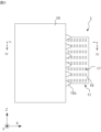
鉄道車両に搭載される車載機器を例にして、車載機器1について説明する。図1に示すように、車載機器1は、鉄道車両100が備える車体101の床下に取り付けられる。図1において、X軸は鉄道車両100の幅方向を示す。Y軸は鉄道車両100の進行方向を示す。Z軸は、X軸およびY軸に直交する。鉄道車両100が水平に位置している状態で、X軸およびY軸は水平方向に延び、Z軸は鉛直方向に延びる。
(Embodiment 1)
The on-vehicle device 1 will be explained by taking as an example the on-vehicle device mounted on a railway vehicle. As shown in FIG. 1, the onboard equipment 1 is attached under the floor of a car body 101 included in a railway vehicle 100. In FIG. 1, the X axis indicates the width direction of the railway vehicle 100. The Y axis indicates the traveling direction of the railway vehicle 100. The Z axis is perpendicular to the X and Y axes. When the railway vehicle 100 is positioned horizontally, the X-axis and the Y-axis extend in the horizontal direction, and the Z-axis extends in the vertical direction.

鉄道車両100は、Y軸正方向またはY軸負方向に進行する。鉄道車両100がY軸正方向に進行すると、Y軸負方向に空気が流れる。一方、鉄道車両100がY軸負方向に進行すると、Y軸正方向に空気が流れる。上述のように、鉄道車両100が走行する際には、鉄道車両100の進行方向の反対方向に向かう空気の流れである走行風が生じる。 The railway vehicle 100 travels in the positive Y-axis direction or the negative Y-axis direction. When the railway vehicle 100 moves in the positive direction of the Y-axis, air flows in the negative direction of the Y-axis. On the other hand, when the railway vehicle 100 moves in the negative direction of the Y-axis, air flows in the positive direction of the Y-axis. As described above, when the railway vehicle 100 travels, a traveling wind, which is a flow of air directed in the direction opposite to the traveling direction of the railway vehicle 100, is generated.

車載機器1は、例えば、電力供給線を介して変電所から電力を取得する集電装置から供給される電力を鉄道車両100の推進力を生じさせる電動機に供給するための三相交流電力に変換して、三相交流電力を電動機に供給する電力変換装置である。車載機器1は、車体101の床下に取り付けられる筐体10と、筐体10に取り付けられる冷却装置11と、鉄道車両100の走行によって生じる走行風の流路に設けられる乱流発生部材12a,12bと、を備える。 The onboard equipment 1 converts, for example, power supplied from a current collector that obtains power from a substation via a power supply line into three-phase AC power for supplying to an electric motor that generates propulsion force for the railway vehicle 100. This is a power conversion device that supplies three-phase AC power to an electric motor. The on-vehicle equipment 1 includes a housing 10 attached to the underfloor of a car body 101, a cooling device 11 attached to the housing 10, and turbulence generating members 12a and 12b provided in a flow path of running air generated by running the railway vehicle 100. and.

筐体10は、図示しない取付部材によって、車体101の床下に取り付けられる。図2および車載機器1をY軸負方向に見た図である図3に示すように、筐体10の外面の内、X軸正方向に向く面に冷却装置11が取り付けられている。図3におけるIV-IV線での矢視断面図である図4および図4におけるV-V線での矢視断面図である図5に示すように、筐体10のX軸正方向に向く面に開口10aが形成されている。開口10aは、冷却装置11によって塞がれている。 The housing 10 is attached to the underfloor of the vehicle body 101 by a mounting member (not shown). As shown in FIG. 2 and FIG. 3, which is a view of the in-vehicle device 1 viewed in the negative direction of the Y-axis, a cooling device 11 is attached to the surface of the outer surface of the housing 10 facing in the positive direction of the X-axis. As shown in FIG. 4, which is a sectional view taken along line IV-IV in FIG. 3, and FIG. 5, which is a sectional view taken along line V-V in FIG. An opening 10a is formed in the surface. The opening 10a is closed by a cooling device 11.

冷却装置11は、放熱対象の電子部品13が取り付けられる受熱ブロック14と、電子部品13から受熱ブロック14を介して伝達された熱を、周囲を流れる走行風に放熱する放熱部15と、放熱部15を覆うカバー16と、を有する。 The cooling device 11 includes a heat receiving block 14 to which an electronic component 13 to be heat radiated is attached, a heat radiating section 15 that radiates heat transferred from the electronic component 13 via the heat receiving block 14 to the traveling wind flowing around it, and a heat radiating section. and a cover 16 that covers 15.

電子部品13は、筐体10に収容され、受熱ブロック14の第1主面14aに取り付けられる。電子部品13は、通電されると発熱する素子、例えば、IGBT(Insulated Gate Bipolar Transistor:絶縁ゲートバイポーラトランジスタ)である。 The electronic component 13 is housed in the housing 10 and attached to the first main surface 14a of the heat receiving block 14. The electronic component 13 is an element that generates heat when energized, such as an IGBT (Insulated Gate Bipolar Transistor).

受熱ブロック14は、電子部品13が取り付けられる第1主面14aと、第1主面14aの反対に位置し、放熱部15が取り付けられる第2主面14bとを有する。電子部品13および放熱部15が取り付けられた受熱ブロック14は、筐体10の開口10aを筐体10の内側から第2主面14bで塞いだ状態で筐体10に取り付けられる。受熱ブロック14は、鉄道車両100の走行時の振動を受けても、受熱ブロック14と筐体10との相対的な位置関係が変化しない程度の強度で筐体10に取り付けられればよい。具体的には、受熱ブロック14は、嵌合、ろう付け、溶接、接着剤を用いた接着、締結部材を用いた締結等の取り付け方法で筐体10の内面に取り付けられる。 The heat receiving block 14 has a first main surface 14a to which the electronic component 13 is attached, and a second main surface 14b located opposite to the first main surface 14a and to which the heat dissipation section 15 is attached. The heat receiving block 14 to which the electronic component 13 and the heat radiation section 15 are attached is attached to the housing 10 with the opening 10a of the housing 10 being closed from the inside of the housing 10 by the second main surface 14b. The heat receiving block 14 may be attached to the casing 10 with such strength that the relative positional relationship between the heat receiving block 14 and the casing 10 does not change even if the heat receiving block 14 receives vibrations when the railway vehicle 100 travels. Specifically, the heat receiving block 14 is attached to the inner surface of the housing 10 by an attachment method such as fitting, brazing, welding, adhesion using an adhesive, or fastening using a fastening member.

例えば、受熱ブロック14は、開口10aを塞ぐことができる大きさの平らな板状部材で形成される。受熱ブロック14は、熱伝導率の高い材料、例えば、銅、アルミニウム等の金属で形成されることが好ましい。 For example, the heat receiving block 14 is formed of a flat plate member large enough to close the opening 10a. The heat receiving block 14 is preferably formed of a material with high thermal conductivity, for example, a metal such as copper or aluminum.

放熱部15は、電子部品13から受熱ブロック14を介して伝達された熱を、走行風に放熱する。これにより、電子部品13が冷却される。実施の形態1では、放熱部15は、複数のフィン15aを有する。各フィン15aは、熱伝導率の高い材料、例えば、銅、アルミニウム等の金属で形成される。 The heat radiating section 15 radiates heat transferred from the electronic component 13 via the heat receiving block 14 to the traveling wind. Thereby, the electronic component 13 is cooled. In the first embodiment, the heat radiation section 15 has a plurality of fins 15a. Each fin 15a is made of a material with high thermal conductivity, for example, a metal such as copper or aluminum.

複数のフィン15aは、主面がXY平面に平行な向きで互いにZ軸方向に離隔して受熱ブロック14の第2主面14bに取り付けられる。各フィン15aは、鉄道車両100の走行時の振動を受けても、各フィン15aと受熱ブロック14との相対的な位置関係が変化しない程度の強度で受熱ブロック14に取り付けられればよい。具体的には、各フィン15aは、嵌合、ろう付け、溶接、接着剤を用いた接着、締結部材を用いた締結等の取り付け方法で受熱ブロック14の第2主面14bに取り付けられる。 The plurality of fins 15a are attached to the second main surface 14b of the heat receiving block 14 with their main surfaces oriented parallel to the XY plane and spaced apart from each other in the Z-axis direction. It is sufficient that each fin 15a is attached to the heat receiving block 14 with such strength that the relative positional relationship between each fin 15a and the heat receiving block 14 does not change even if the railcar 100 receives vibrations during running. Specifically, each fin 15a is attached to the second main surface 14b of the heat receiving block 14 by an attachment method such as fitting, brazing, welding, adhesion using an adhesive, or fastening using a fastening member.

カバー16は、放熱部15を覆って筐体10に取り付けられる。カバー16には、走行風をカバー16の内部に流入させ、または、カバー16の内部に流入した走行風を流出させる通風孔17が形成される。詳細には、カバー16の各面に通風孔17が形成される。カバー16は、鉄道車両100の走行時の振動を受けても、カバー16と筐体10との相対的な位置関係が変化しない程度の強度で筐体10に取り付けられればよい。具体的には、カバー16は、嵌合、ろう付け、溶接、接着剤を用いた接着、締結部材を用いた締結等の取り付け方法で、放熱部15を覆って筐体10に取り付けられる。 The cover 16 is attached to the housing 10 so as to cover the heat radiation section 15 . A ventilation hole 17 is formed in the cover 16 to allow the running wind to flow into the cover 16 or to allow the running wind that has flowed into the cover 16 to flow out. Specifically, ventilation holes 17 are formed on each surface of the cover 16. The cover 16 may be attached to the casing 10 with such strength that the relative positional relationship between the cover 16 and the casing 10 does not change even if the railcar 100 receives vibrations during running. Specifically, the cover 16 is attached to the housing 10 while covering the heat dissipation section 15 by an attachment method such as fitting, brazing, welding, adhesion using an adhesive, or fastening using a fastening member.

図2に示すように、乱流発生部材12a,12bは、走行風の流路、具体的には、車載機器1の近傍における走行風の流路に設けられる。乱流発生部材12a,12bは、走行風の一部の流れを妨げ、走行風の残りの一部を車載機器1に沿って導くことで、乱流を発生させる。車載機器1の近傍における走行風の流路は、例えば、車載機器1の外面からの距離が50ミリメートル以下である車載機器1の周囲の空間である。Y軸正方向またはY軸負方向に進行する鉄道車両100において、冷却装置11に到達するまでの走行風の一部の流れを妨げるために、乱流発生部材12a,12bは、冷却装置11をY軸方向に挟む位置で筐体10の外面に取り付けられる。 As shown in FIG. 2, the turbulence generating members 12a and 12b are provided in a flow path of the traveling wind, specifically, in a flow path of the traveling wind near the on-vehicle equipment 1. The turbulent flow generating members 12a and 12b generate turbulence by obstructing a part of the traveling wind and guiding the remaining part of the traveling wind along the on-vehicle equipment 1. The flow path of the traveling wind near the on-vehicle device 1 is, for example, a space around the on-vehicle device 1 whose distance from the outer surface of the on-vehicle device 1 is 50 mm or less. In the railway vehicle 100 traveling in the Y-axis positive direction or the Y-axis negative direction, the turbulence generating members 12a and 12b prevent the cooling device 11 from partially flowing. It is attached to the outer surface of the housing 10 at a sandwiching position in the Y-axis direction.

実施の形態1では、乱流発生部材12a,12bは、筐体10の外面の内、X軸に交差する面、具体的には、X軸正方向を向く面のY軸方向の両端部に取り付けられる。詳細には、図1および図3に示すように、複数の乱流発生部材12aは、筐体10のX軸正方向を向く面のY軸正方向側の端部にZ軸方向に並んで設けられる。同様に、複数の乱流発生部材12bは、筐体10のX軸正方向を向く面のY軸負方向側の端部にZ軸方向に並んで設けられる。 In the first embodiment, the turbulence generating members 12a and 12b are provided at both ends of the outer surface of the housing 10 in the Y-axis direction on a surface that intersects the X-axis, specifically, on a surface facing in the positive direction of the X-axis. It is attached. Specifically, as shown in FIGS. 1 and 3, the plurality of turbulence generating members 12a are arranged in the Z-axis direction at the end of the surface of the housing 10 facing the X-axis positive direction on the Y-axis positive direction side. provided. Similarly, the plurality of turbulence generating members 12b are arranged in line in the Z-axis direction at the end of the surface of the housing 10 facing the positive X-axis direction on the negative Y-axis side.

例えば、乱流発生部材12a,12bは、錐体の形状を有する。詳細には、乱流発生部材12a,12bは、頂点が面取りされた錐体の形状を有する。頂点が面取りされているため、乱流発生部材12a,12bは、先端が滑らかな突起である。実施の形態1では、乱流発生部材12a,12bは、底面の各辺が30ミリメートル以上、かつ、50ミリメートル以下であって、高さが30ミリメートル以上、かつ、50ミリメートル以下であって、頂点が面取りされた四角錐である。 For example, the turbulence generating members 12a and 12b have a cone shape. Specifically, the turbulence generating members 12a and 12b have a cone shape with a chamfered apex. Since the vertices are chamfered, the turbulence generating members 12a and 12b are protrusions with smooth tips. In the first embodiment, each of the turbulence generating members 12a and 12b has a bottom surface with each side of 30 mm or more and 50 mm or less, a height of 30 mm or more and 50 mm or less, and a top is a square pyramid with a chamfer.

錐体の形状を有する乱流発生部材12a,12bは、錐体の底面が筐体10に当接した状態で、筐体10に取り付けられる。詳細には、乱流発生部材12a,12bは、溶接または締結部材による締結によって、鉄道車両100の走行時の振動を受けても、乱流発生部材12a,12bのそれぞれと筐体10との相対的な位置関係が変化しない程度の強度で筐体10に取り付けられればよい。 The cone-shaped turbulence generating members 12a and 12b are attached to the casing 10 with the bottom surfaces of the cones in contact with the casing 10. Specifically, the turbulence generating members 12a, 12b are welded or fastened together using fastening members, so that even if the railway vehicle 100 is subjected to vibrations during running, the turbulence generating members 12a, 12b and the casing 10 can be connected to each other. It is only necessary to attach it to the housing 10 with enough strength that the physical positional relationship does not change.

乱流発生部材12a,12bは、走行風に含まれる異物、例えば、砂、石等が接触しても損傷しない程度の強度を有する部材で形成されることが好ましい。例えば、乱流発生部材12a,12bは、アルミニウムで形成される。 It is preferable that the turbulence generating members 12a and 12b be formed of a member having enough strength that it will not be damaged even if it comes into contact with foreign matter contained in the traveling wind, such as sand or stones. For example, the turbulence generating members 12a and 12b are made of aluminum.

上記形状の乱流発生部材12a,12bが走行風の流路に設けられることで、走行風の一部の流れが妨げられて、乱流が発生する。換言すれば、走行風の一部が乱流発生部材12a,12bの少なくともいずれかに衝突することによって走行風の一部の流れが妨げられ、走行風の他の一部が各乱流発生部材12aの間または各乱流発生部材12bの間を通って筐体10に沿って流れることで、走行風が乱流となる。 By providing the turbulence generating members 12a and 12b having the above-mentioned shapes in the flow path of the traveling wind, part of the flow of the traveling wind is obstructed, and turbulence is generated. In other words, part of the traveling wind collides with at least one of the turbulence generating members 12a and 12b, so that the flow of a part of the traveling wind is obstructed, and the other part of the traveling wind is directed to each turbulence generating member. The traveling wind becomes turbulent by flowing along the housing 10 through between the turbulence generating members 12a or between the turbulence generating members 12b.

上記構成を有する車載機器1の周囲における走行風の流れについて、鉄道車両100がY軸正方向に進行する場合を例にして、以下に説明する。比較例として、乱流発生部材を備えない車載機器6の周囲における走行風の流れを図6に示す。図6において、車載機器6の周囲における走行風の流れを実線の矢印で示す。車載機器6の構成は、乱流発生部材を除いて、車載機器1の構成と同様である。図の複雑化を避けるため、図6では、車載機器6が備える筐体60と冷却装置61の外形のみが示され、冷却装置61が備えるカバーの通風孔の記載は省略されている。 The flow of running wind around the onboard equipment 1 having the above configuration will be described below, taking as an example the case where the railway vehicle 100 moves in the positive direction of the Y-axis. As a comparative example, FIG. 6 shows the flow of running wind around an on-vehicle device 6 that does not include a turbulence generating member. In FIG. 6, the flow of running wind around the on-vehicle equipment 6 is shown by solid arrows. The configuration of the vehicle-mounted device 6 is similar to the configuration of the vehicle-mounted device 1 except for the turbulence generating member. In order to avoid complication of the drawing, in FIG. 6, only the outer shapes of the casing 60 and the cooling device 61 included in the on-vehicle equipment 6 are shown, and the ventilation holes of the cover included in the cooling device 61 are omitted.

鉄道車両100の進行方向前方から進行方向後方に向かって流れる走行風、換言すれば、Y軸負方向に流れる走行風は、車載機器6の近傍で層流AL1を形成している。車載機器6の周囲に層流AL1が流れることで、車載機器6が備える筐体60の近傍に層流境界層が形成される。筐体60の角によって、走行風の流路の形状が変化するため、図6に一点鎖線で示す領域R1において、筐体60の周りの層流境界層が剥離し、筐体60の近傍に剥離渦AS1が生じる。剥離渦AS1は、一部が走行風と反対方向に向かう空気の流れである。領域R1は、冷却装置61よりY軸正方向側であって、筐体60のX軸正方向に向く面に隣接する領域である。筐体60の端面で走行風が剥離し、走行風の主流は筐体60から離れる方向に流れる。冷却装置61の進行方向前面には、剥離渦AS1が生じるため、冷却装置61の内部に十分な走行風を流入させることが難しい。 The traveling wind that flows from the front in the traveling direction of the railway vehicle 100 toward the rear in the traveling direction, in other words, the traveling wind that flows in the negative direction of the Y-axis forms a laminar flow AL1 in the vicinity of the onboard equipment 6. As the laminar flow AL1 flows around the on-vehicle device 6, a laminar boundary layer is formed in the vicinity of the casing 60 included in the on-vehicle device 6. Since the shape of the flow path of the traveling air changes depending on the corner of the housing 60, the laminar boundary layer around the housing 60 separates in the region R1 shown by the dashed line in FIG. A separation vortex AS1 is generated. The separation vortex AS1 is a flow of air that partially goes in the opposite direction to the traveling wind. The region R1 is a region on the Y-axis positive direction side of the cooling device 61 and adjacent to the surface of the housing 60 facing in the X-axis positive direction. The traveling wind is separated at the end face of the casing 60, and the main flow of the traveling wind flows in a direction away from the casing 60. Since a separated vortex AS1 is generated at the front surface of the cooling device 61 in the traveling direction, it is difficult to allow sufficient running air to flow into the inside of the cooling device 61.

車載機器1の周囲における走行風の流れを図7に示す。図7において、車載機器1の周囲における走行風の流れを実線の矢印で示し、冷却装置11の内部の走行風の流れを点線の矢印で示す。図の複雑化を避けるため、図7では、冷却装置11が備えるカバー16の通風孔17の記載は省略されている。Y軸負方向に流れる走行風は、車載機器1の近傍で層流AL1を形成している。車載機器1の周囲に層流AL1が流れることで、車載機器1が備える筐体10の近傍に層流境界層が形成される。筐体10の角の近傍に乱流発生部材12aが設けられているため、領域R1において、走行風は乱流AT1となる。 FIG. 7 shows the flow of running wind around the on-vehicle equipment 1. In FIG. 7, the flow of running air around the on-vehicle equipment 1 is shown by solid line arrows, and the flow of running air inside cooling device 11 is shown by dotted line arrows. In order to avoid complication of the drawing, the illustration of the ventilation holes 17 of the cover 16 included in the cooling device 11 is omitted in FIG. 7 . The traveling wind flowing in the negative direction of the Y-axis forms a laminar flow AL1 near the on-vehicle equipment 1. As the laminar flow AL1 flows around the vehicle-mounted device 1, a laminar flow boundary layer is formed in the vicinity of the casing 10 included in the vehicle-mounted device 1. Since the turbulence generating member 12a is provided near the corner of the housing 10, the traveling wind becomes a turbulent flow AT1 in the region R1.

乱流発生部材12aによって、乱流AT1が発生することで、換言すれば、走行風が乱流AT1となることで、筐体10の近傍には乱流境界層が形成される。走行風が筐体10の近傍を流れる際は、筐体10の表面での速度勾配が下流に向かうにつれて減少し、速度勾配が0になる位置、すなわち、剥離点において境界層の剥離が生じる。乱流境界層は、層流境界層と比べて、筐体10の表面での速度勾配が大きいため、乱流境界層が形成される位置から剥離点までの距離は、層流境界層が形成される位置から剥離点までの距離より長い。換言すれば、乱流境界層は、層流境界層よりも剥離しにくい。このため、乱流AT1が発生することで、剥離渦の発生が抑制される。 The turbulent flow AT1 is generated by the turbulent flow generating member 12a, in other words, the traveling wind becomes the turbulent flow AT1, so that a turbulent boundary layer is formed in the vicinity of the housing 10. When the traveling wind flows near the housing 10, the velocity gradient on the surface of the housing 10 decreases toward the downstream, and separation of the boundary layer occurs at a position where the velocity gradient becomes 0, that is, a separation point. The turbulent boundary layer has a larger velocity gradient on the surface of the housing 10 than the laminar boundary layer, so the distance from the position where the turbulent boundary layer is formed to the separation point is such that the laminar boundary layer is formed. longer than the distance from the location to the point of separation. In other words, a turbulent boundary layer is less likely to separate than a laminar boundary layer. Therefore, the generation of the turbulent flow AT1 suppresses the generation of separation vortices.

乱流AT1である走行風は、筐体10から離れることおよび筐体10に近づくことを繰り返しながら筐体10に沿ってY軸負方向に流れ、冷却装置11が備えるカバー16の通風孔17を介してカバー16の内部に流入する。カバー16の内部に流入した走行風は、放熱部15が有する図5に示す複数のフィン15aの間を通ることで整流されて、図7に示すように、層流AL2となる。車載機器1においては、車載機器6と比べて、より多くの走行風が冷却装置11に流入するため、車載機器1の冷却性能が向上する。 The traveling wind, which is turbulent flow AT1, flows along the housing 10 in the negative direction of the Y axis while repeatedly moving away from the housing 10 and approaching the housing 10, and passes through the ventilation holes 17 of the cover 16 provided in the cooling device 11. It flows into the inside of the cover 16 through the filter. The running wind that has flowed into the inside of the cover 16 is rectified by passing between the plurality of fins 15a shown in FIG. 5 of the heat radiating part 15, and becomes a laminar flow AL2 as shown in FIG. In the vehicle-mounted device 1, more running air flows into the cooling device 11 compared to the vehicle-mounted device 6, so that the cooling performance of the vehicle-mounted device 1 is improved.

鉄道車両100がY軸負方向に進行する場合も同様に、乱流発生部材12bによって乱流となった走行風が、筐体10から離れることおよび筐体10に近づくことを繰り返しながら筐体10に沿ってY軸正方向に流れ、冷却装置11が備えるカバー16の通風孔17を介してカバー16の内部に流入する。 Similarly, when the railway vehicle 100 moves in the negative direction of the Y-axis, the traveling wind that has become turbulent due to the turbulence generating member 12b repeatedly moves away from the casing 10 and approaches the casing 10. The air flows in the positive direction of the Y-axis along the cooling device 11 and flows into the inside of the cover 16 through the ventilation holes 17 of the cover 16 provided in the cooling device 11 .

乱流発生部材12a,12bは、図6に示すように乱流発生部材12a,12bがない場合に剥離渦が生じる位置である剥離点に相当する位置に設けられることが好ましい。詳細には、鉄道車両100がY軸正方向に進行する場合に剥離渦が生じる位置に乱流発生部材12aが設けられ、鉄道車両100がY軸負方向に進行する場合に剥離渦が生じる位置に乱流発生部材12bが設けられることが好ましい。剥離渦が生じる位置として、走行風の流路の形状が変わる位置、例えば、図7に示すように、筐体10の角の近傍の位置、具体的には、筐体10のX軸正方向に向く面のY軸方向の両端部が用いられてもよいし、シミュレーションによって求められた剥離渦が生じる位置が用いられてもよい。 The turbulence generating members 12a, 12b are preferably provided at positions corresponding to separation points where separation vortices would occur in the absence of the turbulence generating members 12a, 12b, as shown in FIG. Specifically, the turbulence generating member 12a is provided at a position where a separated vortex occurs when the railway vehicle 100 moves in the positive direction of the Y-axis, and the turbulence generating member 12a is provided at a position where a separated vortex occurs when the railway vehicle 100 moves in the negative direction of the Y-axis. It is preferable that the turbulence generating member 12b is provided at the turbulence generating member 12b. The position where the separation vortex is generated is the position where the shape of the flow path of the traveling wind changes, for example, as shown in FIG. Both ends in the Y-axis direction of the surface facing may be used, or a position where a separated vortex is generated determined by simulation may be used.

以上説明した通り、実施の形態1に係る車載機器1において、走行風の流路に設けられる乱流発生部材12a,12bによって乱流が生じることで、剥離渦の発生が抑制されるため、走行風は筐体10に沿って流れる。この結果、冷却装置11により多くの空気を流入させることが可能となり、車載機器1の冷却性能が向上する。車載機器1の冷却性能を向上させるために、車載機器1は、乱流発生部材12a,12bを備えればよく、冷却装置11に向かって延びる導風板を必要としないため、車載機器1の大型化が抑制される。 As explained above, in the vehicle-mounted equipment 1 according to the first embodiment, the turbulence generated by the turbulence generating members 12a and 12b provided in the flow path of the traveling wind suppresses the generation of separated vortices. Wind flows along the housing 10. As a result, it becomes possible to allow more air to flow into the cooling device 11, and the cooling performance of the in-vehicle equipment 1 improves. In order to improve the cooling performance of the on-vehicle equipment 1, the on-vehicle equipment 1 only needs to include the turbulence generating members 12a and 12b, and does not require a baffle plate extending toward the cooling device 11. Increase in size is suppressed.

(実施の形態2)
車載機器の構成は、剥離渦の発生を抑制しながら冷却装置11により多くの走行風を流す構成であればよく、上述の例に限られない。乱流発生部材12aまたは乱流発生部材12bで発生した乱流が整流されてから冷却装置11に流入する車載機器2について実施の形態2で説明する。
(Embodiment 2)
The configuration of the in-vehicle equipment is not limited to the above-mentioned example, as long as it is configured to allow more traveling wind to flow through the cooling device 11 while suppressing the generation of separation vortices. Embodiment 2 describes the vehicle-mounted equipment 2 in which the turbulent flow generated by the turbulent flow generating member 12a or 12b is rectified and then flows into the cooling device 11.

図8に示すように、車載機器2は、実施の形態1に係る車載機器1の構成に加えて、走行風の流路において乱流発生部材12aと冷却装置11との間に設けられ、走行風を整流する整流部材18aと、走行風の流路において乱流発生部材12bと冷却装置11との間に設けられ、走行風を整流する整流部材18bと、を備える。 As shown in FIG. 8, in addition to the configuration of the in-vehicle device 1 according to the first embodiment, the in-vehicle device 2 is provided between the turbulence generating member 12a and the cooling device 11 in the flow path of the traveling wind, and It includes a rectifying member 18a that rectifies the wind, and a rectifying member 18b that is provided between the turbulence generating member 12b and the cooling device 11 in the flow path of the traveling wind and rectifies the traveling wind.

整流部材18a,18bの構成は互いに同じであるため、整流部材18aについて図8におけるIX-IX線での矢視断面図である図9に示す。車載機器2は、Z軸方向に互いに離隔して並べられて、筐体10に取り付けられる複数の整流部材18aを備える。各整流部材18aは、主面がXY平面に平行に位置する板状の形状を有する。同様に、車載機器2は、Z軸方向に互いに離隔して並べられて、筐体10に取り付けられる複数の整流部材18bを備える。 Since the configurations of the flow regulating members 18a and 18b are the same, the flow regulating member 18a is shown in FIG. 9, which is a sectional view taken along the line IX-IX in FIG. 8. The in-vehicle device 2 includes a plurality of rectifying members 18a that are arranged spaced apart from each other in the Z-axis direction and attached to the housing 10. Each rectifying member 18a has a plate-like shape with a main surface located parallel to the XY plane. Similarly, the in-vehicle device 2 includes a plurality of rectifying members 18b that are arranged spaced apart from each other in the Z-axis direction and attached to the housing 10.

各整流部材18a,18bは、鉄道車両100の走行時の振動を受けても、各整流部材18a,18bと筐体10との相対的な位置関係が変化しない程度の強度で筐体10に取り付けられればよい。具体的には、各整流部材18a,18bは、嵌合、ろう付け、溶接、接着剤を用いた接着、締結部材を用いた締結等の取り付け方法で筐体10に取り付けられる。 Each of the rectifying members 18a and 18b is attached to the housing 10 with such strength that the relative positional relationship between each of the rectifying members 18a and 18b and the housing 10 does not change even if the railway vehicle 100 receives vibrations during running. It's fine if you can. Specifically, each of the flow regulating members 18a and 18b is attached to the housing 10 by an attachment method such as fitting, brazing, welding, adhesion using an adhesive, or fastening using a fastening member.

鉄道車両100がY軸正方向に進行する場合、整流部材18aは、乱流発生部材12aで生じた乱流を整流し、冷却装置11に導く。鉄道車両がY軸負方向に進行する場合、整流部材18bは、乱流発生部材12bで生じた乱流を整流し、冷却装置11に導く。乱流が整流されてから冷却装置11に導かれることで、走行風がスムーズに冷却装置11に流れ、車載機器2の冷却性能が向上する。 When the railway vehicle 100 moves in the positive direction of the Y-axis, the rectifying member 18 a rectifies the turbulent flow generated by the turbulent flow generating member 12 a and guides it to the cooling device 11 . When the railway vehicle moves in the negative direction of the Y-axis, the rectifying member 18b rectifies the turbulent flow generated by the turbulent flow generating member 12b and guides it to the cooling device 11. Since the turbulent flow is rectified and then guided to the cooling device 11, the running wind flows smoothly to the cooling device 11, and the cooling performance of the on-vehicle equipment 2 is improved.

上記構成を有する車載機器2の周囲における走行風の流れについて鉄道車両100がY軸正方向に進行する場合を例にして、図10を用いて以下に説明する。図10の見方は図7と同様である。実施の形態1と同様に、Y軸負方向に流れる走行風は、車載機器2の近傍で層流AL1を形成し、領域R1において、走行風は乱流AT1となる。乱流AT1は、整流部材18aによって整流されて層流AL3となる。整流部材18aを通過することで層流AL3となった走行風は、冷却装置11が備えるカバー16の通風孔17を介してカバー16の内部に流入する。カバー16の内部に流入した走行風は、放熱部15が有する複数のフィン15aの間を通ることで再度整流されて、層流AL2となる。 The flow of running wind around the on-vehicle equipment 2 having the above configuration will be described below with reference to FIG. 10, taking as an example the case where the railway vehicle 100 moves in the positive direction of the Y-axis. The view of FIG. 10 is the same as that of FIG. Similar to the first embodiment, the traveling wind flowing in the negative direction of the Y-axis forms a laminar flow AL1 near the on-vehicle equipment 2, and in the region R1, the traveling wind becomes a turbulent flow AT1. The turbulent flow AT1 is rectified by the rectifying member 18a to become a laminar flow AL3. The traveling wind, which has become a laminar flow AL3 by passing through the rectifying member 18a, flows into the inside of the cover 16 through the ventilation hole 17 of the cover 16 included in the cooling device 11. The traveling wind that has flowed into the inside of the cover 16 is rectified again by passing between the plurality of fins 15a of the heat radiating section 15, and becomes a laminar flow AL2.

鉄道車両100がY軸負方向に進行する場合も同様に、乱流発生部材12bによって乱流となった走行風が整流部材18bによって層流となって、冷却装置11が備えるカバー16の通風孔17を介してカバー16の内部に流入する。 Similarly, when the railway vehicle 100 travels in the negative direction of the Y-axis, the traveling wind that has become turbulent due to the turbulence generation member 12b becomes a laminar flow due to the rectification member 18b, and the ventilation holes of the cover 16 included in the cooling device 11 are It flows into the inside of the cover 16 via 17.

整流部材18a,18bのそれぞれと冷却装置11との間隔が長くなると、整流部材18a,18bのそれぞれと冷却装置11との間で層流境界層が剥離して剥離渦が生じ得る。剥離渦の発生を抑制するためには、整流部材18a,18bのそれぞれと冷却装置11との間隔は、剥離渦が生じ得る距離より短いことが好ましい。剥離渦が生じ得る距離は、例えば、シミュレーションによって求めることが可能である。 When the distance between each of the rectifying members 18a, 18b and the cooling device 11 becomes long, the laminar boundary layer may separate between each of the rectifying members 18a, 18b and the cooling device 11, and a separated vortex may occur. In order to suppress the generation of separation vortices, the distance between each of the flow regulating members 18a, 18b and the cooling device 11 is preferably shorter than the distance at which separation vortices can occur. The distance at which a separation vortex can occur can be determined, for example, by simulation.

以上説明した通り、実施の形態2に係る車載機器2において、乱流発生部材12aまたは乱流発生部材12bで乱流となった走行風は、整流部材18aまたは整流部材18bによって整流される。整流部材18aまたは整流部材18bによって整流された走行風は、冷却装置11に導かれる。このため、走行風が冷却装置11によりスムーズに流れ、車載機器2の冷却性能は、車載機器1の冷却性能より高い。 As described above, in the vehicle-mounted device 2 according to the second embodiment, the traveling wind that has become turbulent at the turbulence generating member 12a or 12b is rectified by the rectifying member 18a or 18b. The traveling wind that has been rectified by the rectifying member 18a or 18b is guided to the cooling device 11. Therefore, the running wind flows smoothly through the cooling device 11, and the cooling performance of the on-vehicle equipment 2 is higher than that of the on-vehicle equipment 1.

(実施の形態3)
実施の形態1,2において、車載機器1,2は1つの冷却装置11を備えるが、冷却装置の個数は任意である。複数の冷却装置11a,11bを備える車載機器3について実施の形態3で説明する。
(Embodiment 3)
In the first and second embodiments, the on-vehicle devices 1 and 2 include one cooling device 11, but the number of cooling devices is arbitrary. Embodiment 3 describes an in-vehicle device 3 including a plurality of cooling devices 11a and 11b.

図11に示す車載機器3は、鉄道車両100の進行方向、すなわち、Y軸方向に互いに離隔した位置に並べて設けられる冷却装置11a,11bを備える。冷却装置11a,11bの構成は、実施の形態1に係る車載機器1が備える冷却装置11と同様である。冷却装置11aが備えるカバー16aには、走行風をカバー16aの内部に流入させ、または、カバー16aの内部に流入した走行風を流出させる通風孔17aが形成される。冷却装置11bが備えるカバー16bには、走行風をカバー16bの内部に流入させ、または、カバー16bの内部に流入した走行風を流出させる通風孔17bが形成される。 The onboard equipment 3 shown in FIG. 11 includes cooling devices 11a and 11b that are arranged side by side at positions separated from each other in the traveling direction of the railway vehicle 100, that is, in the Y-axis direction. The configuration of the cooling devices 11a and 11b is the same as that of the cooling device 11 included in the vehicle-mounted equipment 1 according to the first embodiment. A ventilation hole 17a is formed in the cover 16a of the cooling device 11a to allow the running wind to flow into the cover 16a or to allow the running wind that has flowed into the cover 16a to flow out. A ventilation hole 17b is formed in the cover 16b of the cooling device 11b to allow the running wind to flow into the cover 16b or to allow the running wind that has flowed into the cover 16b to flow out.

車載機器3は、冷却装置11aの外面に取り付けられる乱流発生部材19a,19bと、冷却装置11bの外面に取り付けられる乱流発生部材19c,19dと、を備える。乱流発生部材19a-19dの形状および乱流発生部材19a-19dを形成する部材は、実施の形態1に係る車載機器1が備える乱流発生部材12a,12bと同じである。乱流発生部材19a,19bは、冷却装置11aが備えるカバー16aに取り付けられる。実施の形態3では、乱流発生部材19a,19bは、カバー16aのX軸に交差する面、具体的には、X軸正方向を向く面のY軸方向の両端部に取り付けられる。乱流発生部材19c,19dは、冷却装置11bが備えるカバー16bに取り付けられる。実施の形態3では、乱流発生部材19c,19dは、カバー16bのX軸に交差する面、具体的には、X軸正方向を向く面のY軸方向の両端部に取り付けられる。 The on-vehicle device 3 includes turbulence generating members 19a and 19b attached to the outer surface of the cooling device 11a, and turbulence generating members 19c and 19d attached to the outer surface of the cooling device 11b. The shapes of the turbulence generating members 19a to 19d and the members forming the turbulent generating members 19a to 19d are the same as the turbulence generating members 12a and 12b included in the on-vehicle device 1 according to the first embodiment. The turbulence generating members 19a and 19b are attached to a cover 16a included in the cooling device 11a. In the third embodiment, the turbulence generating members 19a and 19b are attached to both ends in the Y-axis direction of the surface of the cover 16a that intersects the X-axis, specifically, the surface facing the positive direction of the X-axis. The turbulence generating members 19c and 19d are attached to a cover 16b included in the cooling device 11b. In the third embodiment, the turbulence generating members 19c and 19d are attached to both ends in the Y-axis direction of the surface of the cover 16b that intersects the X-axis, specifically, the surface facing the positive direction of the X-axis.

乱流発生部材19a-19dが走行風の流路に設けられることで、走行風の一部の流れが妨げられて、乱流が発生する。換言すれば、走行風の一部が乱流発生部材19a-19dの少なくともいずれかに衝突することによって走行風の一部の流れが妨げられ、走行風の他の一部が各乱流発生部材19aの間、各乱流発生部材19bの間、各乱流発生部材19cの間、または、各乱流発生部材19dの間を通ってカバー16aまたはカバー16bに沿って流れることで、走行風が乱流となる。 By providing the turbulence generating members 19a to 19d in the flow path of the traveling wind, part of the flow of the traveling wind is obstructed and turbulence is generated. In other words, part of the traveling wind collides with at least one of the turbulence generating members 19a to 19d, so that the flow of a part of the traveling wind is obstructed, and the other part of the traveling wind is directed to each turbulence generating member. 19a, between each turbulent flow generating member 19b, between each turbulent flow generating member 19c, or between each turbulent flow generating member 19d, and flowing along cover 16a or cover 16b. The flow becomes turbulent.

上記構成を有する車載機器3の周囲における走行風の流れについて、鉄道車両100がY軸正方向に進行する場合を例にして、以下に説明する。比較例として、乱流発生部材を備えない車載機器7の周囲における走行風の流れを図12に示す。図12の見方は、図6と同様である。車載機器7の構成は、乱流発生部材を除いて、車載機器3の構成と同様である。図の複雑化を避けるため、図12では、車載機器7が備える筐体70と冷却装置71a,71bの外形のみが示され、冷却装置71a,71bが備えるカバーの通風孔の記載は省略されている。 The flow of running air around the on-vehicle equipment 3 having the above configuration will be described below, taking as an example the case where the railway vehicle 100 moves in the positive direction of the Y-axis. As a comparative example, FIG. 12 shows the flow of running wind around an on-vehicle device 7 that does not include a turbulence generating member. The view of FIG. 12 is the same as that of FIG. The configuration of the vehicle-mounted device 7 is the same as that of the vehicle-mounted device 3 except for the turbulence generating member. In order to avoid complication of the diagram, in FIG. 12, only the external shapes of the housing 70 and the cooling devices 71a, 71b included in the on-vehicle equipment 7 are shown, and the description of the ventilation holes of the covers provided in the cooling devices 71a, 71b is omitted. There is.

Y軸負方向に流れる走行風は、車載機器7の近傍で層流AL1を形成している。車載機器7の周囲に層流AL1が流れることで、車載機器7が備える筐体70の近傍に層流境界層が形成される。筐体70の角によって、走行風の流路の形状が変化するため、図12に一点鎖線で示す領域R2において、筐体70の周りの層流境界層が剥離することで、筐体70の近傍に剥離渦AS1が生じる。領域R2は、冷却装置71aより鉄道車両100の進行方向前方、換言すれば、冷却装置71aよりY軸正方向側であって、筐体70のX軸正方向に向く面に隣接する領域である。筐体70の端面で走行風が剥離し、走行風の主流は筐体70から離れる方向に流れる。冷却装置71aの進行方向前面には、剥離渦AS1が生じるため、冷却装置71aの内部に十分な走行風を流入させることが難しい。 The traveling wind flowing in the negative direction of the Y-axis forms a laminar flow AL1 near the on-vehicle equipment 7. As the laminar flow AL1 flows around the vehicle-mounted device 7, a laminar flow boundary layer is formed in the vicinity of the casing 70 included in the vehicle-mounted device 7. Since the shape of the flow path of the traveling air changes depending on the corner of the casing 70, the laminar boundary layer around the casing 70 separates in the region R2 shown by the dashed line in FIG. A separation vortex AS1 is generated nearby. Region R2 is a region ahead of the cooling device 71a in the traveling direction of the railway vehicle 100, in other words, a region on the Y-axis positive direction side of the cooling device 71a and adjacent to the surface of the casing 70 facing in the X-axis positive direction. . The traveling wind is separated at the end face of the casing 70, and the main flow of the traveling wind flows in a direction away from the casing 70. Since a separated vortex AS1 is generated at the front surface of the cooling device 71a in the traveling direction, it is difficult to allow sufficient running air to flow into the inside of the cooling device 71a.

冷却装置71aは、筐体70の外面からX軸正方向に突出しているため、冷却装置71aによって、走行風の流路の形状が変化する。このため、冷却装置71aよりX軸正方向側に位置する領域R3において、冷却装置71aの周りの層流境界層が剥離することで、冷却装置71aの近傍に剥離渦AS2が生じる。冷却装置71aの端面で走行風が剥離し、走行風の主流は冷却装置71aから離れる方向に流れる。冷却装置71aのX軸正方向側に剥離渦AS2が生じるため、冷却装置71aの内部に十分な走行風を流入させることが難しい。 Since the cooling device 71a protrudes from the outer surface of the housing 70 in the positive direction of the X-axis, the shape of the flow path of the traveling air changes due to the cooling device 71a. Therefore, in the region R3 located on the positive side of the X-axis from the cooling device 71a, the laminar boundary layer around the cooling device 71a is separated, and a separated vortex AS2 is generated in the vicinity of the cooling device 71a. The traveling wind is separated at the end face of the cooling device 71a, and the main flow of the traveling wind flows in a direction away from the cooling device 71a. Since the separation vortex AS2 is generated on the positive side of the X-axis of the cooling device 71a, it is difficult to allow sufficient running air to flow into the inside of the cooling device 71a.

冷却装置71a,71bはY軸方向に間隔を空けて設けられているため、冷却装置71aよりY軸負方向側であって、かつ、冷却装置71bよりY軸正方向側に位置する領域R4において、走行風の流路の形状が変化する。このため、領域R4において、筐体70の周りの層流境界層が剥離することで、筐体70の近傍に剥離渦AS3が生じる。冷却装置71a,71bの間であって、筐体71のX軸正方向側で走行風が剥離し、走行風の主流は筐体70から離れる方向に流れる。冷却装置71bの進行方向前面には、剥離渦AS3が生じるため、冷却装置71bの内部に十分な走行風を流入させることが難しい。 Since the cooling devices 71a and 71b are provided at intervals in the Y-axis direction, in the region R4 located on the negative side of the Y-axis from the cooling device 71a and on the positive side of the Y-axis from the cooling device 71b. , the shape of the traveling wind flow path changes. Therefore, in the region R4, the laminar boundary layer around the casing 70 separates, and a separation vortex AS3 is generated in the vicinity of the casing 70. Between the cooling devices 71a and 71b, the traveling wind separates on the X-axis positive direction side of the housing 71, and the main flow of the traveling wind flows in a direction away from the housing 70. Since a separation vortex AS3 is generated at the front surface of the cooling device 71b in the traveling direction, it is difficult to allow sufficient running air to flow into the inside of the cooling device 71b.

冷却装置71bは、筐体70の外面からX軸正方向に突出しているため、冷却装置71bによって、走行風の流路の形状が変化する。このため、冷却装置71bよりX軸正方向側に位置する領域R5において、冷却装置71bの周りの層流境界層が剥離することで、冷却装置71bの近傍に剥離渦AS4が生じる。冷却装置71bの端面で走行風が剥離し、走行風の主流は冷却装置71bから離れる方向に流れる。冷却装置71bのX軸正方向側に剥離渦AS4が生じるため、冷却装置71bの内部に十分な走行風を流入させることが難しい。 Since the cooling device 71b protrudes from the outer surface of the casing 70 in the positive direction of the X-axis, the shape of the flow path of the running air changes due to the cooling device 71b. Therefore, in the region R5 located on the positive side of the X-axis from the cooling device 71b, the laminar boundary layer around the cooling device 71b is separated, and a separated vortex AS4 is generated in the vicinity of the cooling device 71b. The traveling wind is separated at the end face of the cooling device 71b, and the main flow of the traveling wind flows in a direction away from the cooling device 71b. Since the separation vortex AS4 is generated on the positive side of the X-axis of the cooling device 71b, it is difficult to allow sufficient running air to flow into the inside of the cooling device 71b.

車載機器3の周囲における走行風の流れを図13に示す。図の見方は、図7と同様である。図の複雑化を避けるため、図13では、冷却装置11a,11bが備えるカバー16a,16bの通風孔17a,17bの記載は省略されている。Y軸負方向に流れる走行風は、車載機器3の近傍で層流AL1を形成している。車載機器3の周囲に層流AL1が流れることで、車載機器3が備える筐体10の近傍に層流境界層が形成される。図12と同様に、領域R2において、筐体10の周りの層流境界層が剥離することで、筐体10の近傍に剥離渦AS1が生じる。 FIG. 13 shows the flow of running wind around the on-vehicle equipment 3. The view of the figure is the same as that of FIG. In order to avoid complication of the drawing, the ventilation holes 17a and 17b of the covers 16a and 16b provided in the cooling devices 11a and 11b are omitted in FIG. 13. The traveling wind flowing in the negative direction of the Y-axis forms a laminar flow AL1 near the on-vehicle equipment 3. As the laminar flow AL1 flows around the on-vehicle device 3, a laminar boundary layer is formed in the vicinity of the casing 10 included in the on-vehicle device 3. Similarly to FIG. 12, in region R2, the laminar boundary layer around the casing 10 separates, and a separation vortex AS1 is generated near the casing 10.

図13に示すように、冷却装置11aのカバー16aの角に乱流発生部材19aが設けられているため、領域R3において、走行風は乱流AT1となる。乱流AT1は、冷却装置11aから離れることおよび冷却装置11aに近づくことを繰り返しながらカバー16aに沿ってY軸負方向に流れる。 As shown in FIG. 13, since the turbulence generating member 19a is provided at the corner of the cover 16a of the cooling device 11a, the traveling wind becomes turbulent AT1 in the region R3. The turbulent flow AT1 flows in the Y-axis negative direction along the cover 16a while repeatedly moving away from the cooling device 11a and approaching the cooling device 11a.

乱流発生部材19aによって、乱流AT1が発生することで、換言すれば、走行風が乱流AT1となることで、冷却装置11aの近傍には乱流境界層が形成される。実施の形態1で説明したように、乱流境界層は、層流境界層よりも剥離しにくい。このため、乱流AT1が発生することで、剥離渦の発生が抑制される。 The turbulent flow AT1 is generated by the turbulent flow generation member 19a, in other words, the traveling wind becomes the turbulent flow AT1, so that a turbulent boundary layer is formed in the vicinity of the cooling device 11a. As described in Embodiment 1, a turbulent boundary layer is less likely to separate than a laminar boundary layer. Therefore, the generation of the turbulent flow AT1 suppresses the generation of separation vortices.

この結果、乱流AT1である走行風は冷却装置11aから離れることおよび冷却装置11aに近づくことを繰り返しながらY軸負方向に流れ、乱流AT1である走行風の一部は、冷却装置11aが備えるカバー16aの通風孔17aを介してカバー16aの内部に流入する。カバー16aの内部に流入した走行風は、放熱部15が有する複数のフィン15aの間を通ることで整流されて、層流AL2となる。 As a result, the traveling wind which is turbulent flow AT1 flows in the negative direction of the Y axis while repeating leaving the cooling device 11a and approaching the cooling device 11a, and a part of the traveling wind which is turbulent flow AT1 is caused by the cooling device 11a. It flows into the inside of the cover 16a through the ventilation holes 17a of the cover 16a. The traveling wind that has flowed into the cover 16a is rectified by passing between the plurality of fins 15a of the heat radiating section 15, and becomes a laminar flow AL2.

乱流AT1である走行風の他の一部は、冷却装置11aに沿ってY軸負方向に流れ、乱流発生部材19bにぶつかることで、領域R4において、乱流AT2となる。乱流AT2の一部は、筐体10から離れることおよび筐体10に近づくことを繰り返しながら筐体10に沿ってY軸負方向に流れる。 Another part of the traveling wind, which is the turbulent flow AT1, flows along the cooling device 11a in the negative direction of the Y-axis and hits the turbulent flow generating member 19b, thereby becoming a turbulent flow AT2 in the region R4. A part of the turbulent flow AT2 flows along the housing 10 in the negative direction of the Y-axis while repeatedly moving away from the housing 10 and approaching the housing 10.

乱流AT2である走行風の一部が筐体10に向かって流れ、冷却装置11aが備える放熱部15が有する複数のフィン15aの間を通ることで層流AL2となった走行風と混ざる。この結果、層流AL2が、乱流AT3となるため、冷却装置11a,11bに挟まれた筐体10の近傍には乱流境界層が形成される。実施の形態1で説明したように、乱流境界層は、層流境界層より剥離しにくい。このため、乱流AT3が発生することで、剥離渦の発生が抑制される。 A part of the traveling wind which is turbulent flow AT2 flows toward the housing 10, and mixes with the traveling wind which has become laminar flow AL2 by passing between the plurality of fins 15a of the heat radiating section 15 included in the cooling device 11a. As a result, the laminar flow AL2 becomes a turbulent flow AT3, so that a turbulent boundary layer is formed near the housing 10 sandwiched between the cooling devices 11a and 11b. As described in the first embodiment, a turbulent boundary layer is less likely to separate than a laminar boundary layer. Therefore, the generation of the turbulent flow AT3 suppresses the generation of separation vortices.

この結果、乱流AT3である走行風は筐体10から離れることおよび筐体10に近づくことを繰り返しながら筐体10に沿ってY軸負方向に流れ、冷却装置11bが備えるカバー16bの通風孔17bを介してカバー16bの内部に流入する。カバー16bの内部に流入した走行風は、放熱部15が有する複数のフィン15aの間を通ることで整流されて、層流AL3となる。 As a result, the traveling wind, which is turbulent flow AT3, flows in the negative direction of the Y axis along the housing 10 while repeatedly moving away from the housing 10 and approaching the housing 10, and the ventilation holes of the cover 16b provided in the cooling device 11b It flows into the inside of the cover 16b via 17b. The running wind that has flowed into the inside of the cover 16b is rectified by passing between the plurality of fins 15a of the heat radiating section 15, and becomes a laminar flow AL3.

乱流AT2である走行風の他の一部は、Y軸負方向に流れる。冷却装置11bのカバー16bの角に乱流発生部材19cが設けられているため、領域R5において、走行風は乱流AT4となる。乱流発生部材19cによって、乱流AT4が発生することで、換言すれば、走行風が乱流AT4となることで、カバー16bの近傍には乱流境界層が形成される。実施の形態1で説明したように、乱流境界層は、層流境界層より剥離しにくい。このため、乱流AT4が発生することで、剥離渦の発生が抑制される。 The other part of the traveling wind, which is the turbulent flow AT2, flows in the negative direction of the Y-axis. Since the turbulence generating member 19c is provided at the corner of the cover 16b of the cooling device 11b, the traveling wind becomes a turbulent flow AT4 in the region R5. The turbulent flow generation member 19c generates the turbulent flow AT4, in other words, the traveling wind becomes the turbulent flow AT4, so that a turbulent boundary layer is formed in the vicinity of the cover 16b. As described in the first embodiment, a turbulent boundary layer is less likely to separate than a laminar boundary layer. Therefore, the generation of the turbulent flow AT4 suppresses the generation of separation vortices.

この結果、乱流AT4である走行風は冷却装置11bから離れることおよび冷却装置11bに近づくことを繰り返しながら冷却装置11bに沿ってY軸負方向に流れ、乱流AT4である走行風の一部は、冷却装置11bが備えるカバー16bの通風孔17bを介してカバー16bの内部に流入する。カバー16bの内部に流入した走行風は、放熱部15が有する複数のフィン15aの間を通ることで整流されて、層流AL3となる。 As a result, the traveling wind which is turbulent flow AT4 flows in the negative direction of the Y axis along the cooling device 11b while repeating leaving the cooling device 11b and approaching the cooling device 11b, and part of the traveling wind which is turbulent flow AT4. flows into the inside of the cover 16b through the ventilation holes 17b of the cover 16b included in the cooling device 11b. The running wind that has flowed into the inside of the cover 16b is rectified by passing between the plurality of fins 15a of the heat radiating section 15, and becomes a laminar flow AL3.

上述のように、車載機器3においては、車載機器7と比べて、より多くの走行風が冷却装置11a,11bに流入するため、車載機器3の冷却性能が向上する。 As described above, in the vehicle-mounted device 3, more traveling wind flows into the cooling devices 11a and 11b compared to the vehicle-mounted device 7, so that the cooling performance of the vehicle-mounted device 3 is improved.

鉄道車両100がY軸負方向に進行する場合も同様に、乱流発生部材19dによって乱流となった走行風が、冷却装置11bが備えるカバー16bの通風孔17bを介してカバー16bの内部に流入する。乱流発生部材19cによって乱流となった走行風の一部が、冷却装置11bが備える放熱部15が有する複数のフィン15aの間を通ることで整流されて、層流となった走行風に混ざることで、乱流が発生する。発生した乱流は筐体10に沿ってY軸正方向に流れ、冷却装置11aが備えるカバー16aの通風孔17aを介してカバー16aの内部に流入する。さらに、乱流発生部材19bによって乱流となった走行風が、冷却装置11aが備えるカバー16aの通風孔17aを介してカバー16aの内部に流入する。 Similarly, when the railway vehicle 100 moves in the negative direction of the Y-axis, the traveling wind that has become turbulent due to the turbulence generating member 19d enters the inside of the cover 16b through the ventilation hole 17b of the cover 16b included in the cooling device 11b. Inflow. A part of the traveling wind that has become turbulent due to the turbulence generating member 19c is rectified by passing between the plurality of fins 15a of the heat radiating section 15 included in the cooling device 11b, and becomes a laminar traveling wind. Mixing causes turbulence. The generated turbulent flow flows in the positive direction of the Y-axis along the housing 10 and flows into the inside of the cover 16a through the ventilation holes 17a of the cover 16a included in the cooling device 11a. Furthermore, the traveling wind that has become turbulent due to the turbulence generating member 19b flows into the inside of the cover 16a through the ventilation holes 17a of the cover 16a included in the cooling device 11a.

乱流発生部材19a-19dは、図12に示すように乱流発生部材19a-19dがない場合に剥離渦が生じる位置である剥離点に相当する位置に設けられることが好ましい。詳細には、図13に示すように、乱流発生部材19aは、カバー16aのX軸正方向に向く面のY軸正方向側の端部に設けられることが好ましい。乱流発生部材19bは、カバー16aのX軸正方向に向く面のY軸負方向側の端部に設けられることが好ましい。乱流発生部材19cは、カバー16bのX軸正方向に向く面のY軸正方向側の端部に設けられることが好ましい。乱流発生部材19dは、カバー16bのX軸正方向に向く面のY軸負方向側の端部に設けられることが好ましい。 The turbulence generating members 19a-19d are preferably provided at positions corresponding to separation points where separation vortices would occur in the absence of the turbulence generating members 19a-19d, as shown in FIG. Specifically, as shown in FIG. 13, the turbulence generating member 19a is preferably provided at the end of the surface of the cover 16a facing in the positive X-axis direction on the positive Y-axis side. The turbulence generating member 19b is preferably provided at the end of the surface of the cover 16a facing in the positive direction of the X-axis on the negative direction of the Y-axis. The turbulence generating member 19c is preferably provided at the end of the surface of the cover 16b facing in the positive X-axis direction on the positive Y-axis direction side. The turbulence generating member 19d is preferably provided at the end of the surface of the cover 16b facing in the positive direction of the X-axis on the negative direction of the Y-axis.

以上説明した通り、実施の形態3に係る車載機器3において、走行風の流路に設けられる乱流発生部材19a-19dによって乱流が生じることで、剥離渦の発生が抑制されるため、走行風が冷却装置11a,11bに流入する。この結果、冷却装置11a,11bにより多くの空気を流入させることが可能となる。 As explained above, in the in-vehicle equipment 3 according to the third embodiment, the generation of separated vortices is suppressed by the generation of turbulent flow by the turbulence generating members 19a to 19d provided in the flow path of the traveling wind. Wind flows into the cooling devices 11a, 11b. As a result, it becomes possible to allow more air to flow into the cooling devices 11a and 11b.

(実施の形態4)
実施の形態1,2では、車載機器1,2が備える筐体10の外面に乱流発生部材12a,12bが取り付けられている。乱流発生部材12a,12bは、走行風の流路において、冷却装置11に到達するまでの走行風の一部の流れを妨げることができる位置であれば任意の位置に設けることが可能である。筐体10の外部で筐体10に隣接した位置、具体的には、鉄道車両100に取り付けられる装置の外面に取り付けられる乱流発生部材20a,20bを備える車載機器4について実施の形態4で説明する。
(Embodiment 4)
In the first and second embodiments, turbulence generating members 12a and 12b are attached to the outer surface of the housing 10 included in the on-vehicle devices 1 and 2. The turbulence generating members 12a and 12b can be provided at any position in the flow path of the traveling wind as long as it can obstruct the flow of a portion of the traveling wind until it reaches the cooling device 11. . In Embodiment 4, an on-vehicle device 4 including turbulence generating members 20a and 20b attached to a position outside the casing 10 and adjacent to the casing 10, specifically, on the outer surface of the device attached to the railway vehicle 100, will be described. do.

図14に示すように、鉄道車両100の車体101の床下には、装置102a,102bが取り付けられる。図15に示すように、装置102a,102bのX軸方向の長さは、車載機器4のX軸方向の長さより長い。車載機器4は、装置102aに取り付けられる乱流発生部材20a,20bと、装置102bに取り付けられる乱流発生部材20c,20dと、を備える。乱流発生部材20a-20dの形状および乱流発生部材20a-20dを形成する部材は、実施の形態1に係る車載機器1が備える乱流発生部材12a,12bと同じである。 As shown in FIG. 14, devices 102a and 102b are installed under the floor of a car body 101 of a railway vehicle 100. As shown in FIG. 15, the lengths of the devices 102a and 102b in the X-axis direction are longer than the length of the in-vehicle equipment 4 in the X-axis direction. The on-vehicle device 4 includes turbulence generating members 20a and 20b attached to the device 102a, and turbulence generating members 20c and 20d attached to the device 102b. The shapes of the turbulence generating members 20a-20d and the members forming the turbulent flow generating members 20a-20d are the same as the turbulence generating members 12a, 12b included in the on-vehicle device 1 according to the first embodiment.

乱流発生部材20a-20dは、走行風の流路、具体的には、車載機器4に隣接している装置102a,102bの近傍における走行風の流路に設けられ、走行風の一部の流れを妨げ、残りの一部を装置102a,102bに沿って導くことで乱流を発生させる。装置102a,102bの近傍における走行風の流路は、例えば、装置102a,102bの外面からの距離が50ミリメートル以下である装置102a,102bの周囲の空間である。乱流発生部材20a,20bは、装置102aのX軸に交差する面、具体的には、X軸正方向を向く面のY軸方向の両端部に取り付けられる。乱流発生部材20c,20dは、装置102bのX軸に交差する面、具体的には、X軸正方向を向く面のY軸方向の両端部に取り付けられる。 The turbulence generating members 20a to 20d are provided in the flow path of the traveling wind, specifically, in the vicinity of the devices 102a and 102b adjacent to the on-vehicle equipment 4, and are provided in the flow path of the traveling wind in the vicinity of the devices 102a and 102b adjacent to the on-vehicle equipment 4. Turbulent flow is generated by blocking the flow and directing the remaining portion along devices 102a and 102b. The flow path of the traveling air in the vicinity of the devices 102a, 102b is, for example, the space around the devices 102a, 102b whose distance from the outer surface of the devices 102a, 102b is 50 mm or less. The turbulence generating members 20a and 20b are attached to a surface of the device 102a that intersects with the X-axis, specifically, to both ends of the surface facing in the positive direction of the X-axis in the Y-axis direction. The turbulence generating members 20c and 20d are attached to a surface of the device 102b that intersects with the X-axis, specifically, to both ends of the surface facing in the positive direction of the X-axis in the Y-axis direction.

上記構成を有する車載機器4の周囲における走行風の流れについて、鉄道車両100がY軸正方向に進行する場合を例にして、以下に説明する。比較例として、乱流発生部材を備えない車載機器8の周囲における走行風の流れを図16に示す。図16の見方は、図6と同様である。車載機器8の構成は、乱流発生部材を除いて、車載機器4の構成と同様である。図16に示すように、装置102a,102bのX軸方向の長さは、車載機器8のX軸方向の長さより長い。図の複雑化を避けるため、図16では、車載機器8が備える筐体80と冷却装置81の外形のみが示され、冷却装置81が備えるカバーの通風孔の記載は省略されている。 The flow of running air around the on-vehicle equipment 4 having the above configuration will be described below, taking as an example the case where the railway vehicle 100 moves in the positive direction of the Y-axis. As a comparative example, FIG. 16 shows the flow of running wind around an on-vehicle device 8 that does not include a turbulence generating member. The view of FIG. 16 is the same as that of FIG. The configuration of the vehicle-mounted device 8 is the same as that of the vehicle-mounted device 4 except for the turbulence generating member. As shown in FIG. 16, the lengths of the devices 102a and 102b in the X-axis direction are longer than the length of the in-vehicle equipment 8 in the X-axis direction. In order to avoid complication of the drawing, in FIG. 16, only the outer shapes of the casing 80 and the cooling device 81 included in the in-vehicle equipment 8 are shown, and the ventilation holes of the cover included in the cooling device 81 are omitted.

Y軸負方向に流れる走行風は、装置102aの近傍で層流AL1を形成している。装置102aの周囲に層流AL1が流れることで、装置102aの近傍に層流境界層が形成される。装置102aの角によって、走行風の流路の形状が変化するため、図16に一点鎖線で示す領域R6において、装置102aの周りの層流境界層が剥離することで、装置102aの近傍に剥離渦AS1が生じる。領域R6は、装置102aのX軸正方向側に位置する領域である。装置102aの端面で走行風が剥離し、走行風の主流は装置102aから離れる方向に流れる。 The traveling wind flowing in the negative direction of the Y-axis forms a laminar flow AL1 in the vicinity of the device 102a. As the laminar flow AL1 flows around the device 102a, a laminar boundary layer is formed in the vicinity of the device 102a. Since the shape of the traveling wind flow path changes depending on the corner of the device 102a, the laminar boundary layer around the device 102a separates in the region R6 shown by the dashed line in FIG. 16, causing separation near the device 102a. A vortex AS1 is created. Region R6 is a region located on the positive side of the X-axis of the device 102a. The traveling wind is separated at the end face of the device 102a, and the main flow of the traveling wind flows in a direction away from the device 102a.

上述のように、装置102aのX軸方向の長さは、車載機器8のX軸方向の長さより長い。このため、車載機器8の筐体80よりX軸正方向であって、冷却装置81よりY軸正方向側に位置する領域R7において、走行風の流路の形状が変化する。このため、領域R7において、筐体80の周りの層流境界層が剥離することで、筐体80の近傍に剥離渦AS2が生じる。筐体80の端面で走行風が剥離し、走行風の主流は筐体80から離れる方向に流れる。冷却装置81の進行方向前面には、上述のように剥離渦AS1,AS2が生じるため、冷却装置81の内部に十分な走行風を流入させることが難しい。 As described above, the length of the device 102a in the X-axis direction is longer than the length of the in-vehicle device 8 in the X-axis direction. Therefore, in the region R7 located in the positive direction of the X-axis from the housing 80 of the vehicle-mounted equipment 8 and in the positive direction of the Y-axis from the cooling device 81, the shape of the flow path of the traveling air changes. Therefore, in the region R7, the laminar boundary layer around the casing 80 separates, and a separation vortex AS2 is generated in the vicinity of the casing 80. The traveling wind is separated at the end face of the casing 80, and the main flow of the traveling wind flows in a direction away from the casing 80. As described above, separation vortices AS1 and AS2 are generated at the front surface of the cooling device 81 in the traveling direction, so that it is difficult to allow sufficient running air to flow into the inside of the cooling device 81.

車載機器4の周囲における走行風の流れを図17に示す。図の見方は、図7と同様である。図の複雑化を避けるため、図17では、冷却装置11が備えるカバー16の通風孔17の記載は省略されている。Y軸負方向に流れる走行風は、装置102aの近傍で層流AL1を形成している。装置102aの周囲に層流AL1が流れることで、装置102aの近傍に層流境界層が形成される。装置102aの角の近傍に乱流発生部材20aが設けられているため、領域R6において、走行風は乱流AT1となる。 FIG. 17 shows the flow of running wind around the on-vehicle equipment 4. The view of the figure is the same as that of FIG. In order to avoid complication of the drawing, the illustration of the ventilation holes 17 of the cover 16 included in the cooling device 11 is omitted in FIG. 17 . The traveling wind flowing in the negative direction of the Y-axis forms a laminar flow AL1 in the vicinity of the device 102a. As the laminar flow AL1 flows around the device 102a, a laminar boundary layer is formed in the vicinity of the device 102a. Since the turbulence generating member 20a is provided near the corner of the device 102a, the traveling wind becomes turbulent AT1 in the region R6.

乱流発生部材20aによって、乱流AT1が発生することで、換言すれば、走行風が乱流AT1となることで、装置102aの近傍には乱流境界層が形成される。実施の形態1で説明したように、乱流境界層は、層流境界層よりも剥離しにくい。このため、乱流AT1が発生することで、剥離渦の発生が抑制される。 The turbulent flow AT1 is generated by the turbulent flow generation member 20a, in other words, the traveling wind becomes the turbulent flow AT1, so that a turbulent boundary layer is formed in the vicinity of the device 102a. As described in Embodiment 1, a turbulent boundary layer is less likely to separate than a laminar boundary layer. Therefore, the generation of the turbulent flow AT1 suppresses the generation of separation vortices.

この結果、乱流AT1である走行風は装置102aから離れることおよび装置102aに近づくことを繰り返しながら装置102aに沿ってY軸負方向に流れる。上述のようにY軸負方向に流れる走行風が乱流発生部材12bにぶつかることで、領域R7において、乱流AT2が発生する。 As a result, the traveling wind, which is turbulent flow AT1, flows in the negative direction of the Y-axis along the device 102a while repeatedly moving away from the device 102a and approaching the device 102a. As described above, when the traveling wind flowing in the negative direction of the Y-axis collides with the turbulence generating member 12b, turbulence AT2 is generated in region R7.

乱流AT2である走行風の一部が筐体10に向かって流れ、筐体10の近傍には乱流境界層が形成される。実施の形態1で説明したように、乱流境界層は、層流境界層よりも剥離しにくい。このため、乱流AT2が発生することで、剥離渦の発生が抑制される。 A part of the traveling wind that is turbulent AT2 flows toward the housing 10, and a turbulent boundary layer is formed in the vicinity of the housing 10. As described in Embodiment 1, a turbulent boundary layer is less likely to separate than a laminar boundary layer. Therefore, the generation of the turbulent flow AT2 suppresses the generation of separation vortices.

この結果、乱流AT2である走行風は筐体10から離れることおよび筐体10に近づくことを繰り返しながら筐体10に沿ってY軸負方向に流れ、冷却装置11が備えるカバー16の通風孔17を介してカバー16の内部に流入する。カバー16の内部に流入した走行風は、放熱部15が有する複数のフィン15aの間を通ることで整流されて、層流AL2となる。車載機器4においては、車載機器8と比べて、より多くの走行風が冷却装置11に流入するため、車載機器4の冷却性能が向上する。 As a result, the traveling wind, which is turbulent flow AT2, flows in the negative direction of the Y-axis along the housing 10 while repeatedly moving away from the housing 10 and approaching the housing 10, and the air vents of the cover 16 provided in the cooling device 11 flow. It flows into the inside of the cover 16 via 17. The running wind that has flowed into the inside of the cover 16 is rectified by passing between the plurality of fins 15a of the heat radiating section 15, and becomes a laminar flow AL2. In the vehicle-mounted device 4, more running air flows into the cooling device 11 compared to the vehicle-mounted device 8, so that the cooling performance of the vehicle-mounted device 4 is improved.

鉄道車両100がY軸負方向に進行する場合も同様に、乱流発生部材20dによって乱流となった走行風が装置102bから離れることおよび装置102bに近づくことを繰り替えしながら装置102bに沿ってY軸正方向に流れる。そして、乱流発生部材20cによって再度乱流となった走行風が筐体10に向かって流れ、冷却装置11が備えるカバー16の通風孔17を介してカバー16の内部に流入する。 Similarly, when the railway vehicle 100 moves in the negative direction of the Y-axis, the traveling wind that has become turbulent due to the turbulence generating member 20d moves along the device 102b while repeatedly moving away from the device 102b and approaching the device 102b. Flows in the positive direction of the Y-axis. Then, the traveling wind, which has become turbulent again by the turbulence generating member 20c, flows toward the housing 10 and flows into the inside of the cover 16 through the ventilation holes 17 of the cover 16 included in the cooling device 11.

乱流発生部材20a-20dは、図16に示すように乱流発生部材20a-20dがない場合に剥離渦が生じる位置である剥離点に相当する位置に設けられることが好ましい。詳細には、図17に示すように、乱流発生部材20aは、装置102aのX軸正方向に向く面のY軸正方向側の端部に設けられることが好ましい。乱流発生部材20bは、装置102aのX軸正方向に向く面のY軸負方向側の端部に設けられることが好ましい。乱流発生部材20cは、装置102bのX軸正方向に向く面のY軸正方向側の端部に設けられることが好ましい。乱流発生部材20dは、装置102bのX軸正方向に向く面のY軸負方向側の端部に設けられることが好ましい。 The turbulence generating members 20a-20d are preferably provided at positions corresponding to separation points where separation vortices would occur in the absence of the turbulence generating members 20a-20d, as shown in FIG. Specifically, as shown in FIG. 17, the turbulence generating member 20a is preferably provided at the end of the surface of the device 102a facing in the positive X-axis direction on the positive Y-axis side. The turbulence generating member 20b is preferably provided at the end of the surface of the device 102a facing in the positive direction of the X-axis on the negative direction of the Y-axis. The turbulence generating member 20c is preferably provided at the end of the surface of the device 102b on the Y-axis positive direction side of the surface facing in the X-axis positive direction. The turbulence generating member 20d is preferably provided at the end of the surface of the device 102b facing in the positive direction of the X-axis on the negative direction of the Y-axis.

以上説明した通り、実施の形態4に係る車載機器4において、鉄道車両100に取り付けられる装置102a,102bに取り付けられる乱流発生部材20a-20dによって乱流が生じることで、剥離渦の発生が抑制されるため、走行風が冷却装置11に流入する。この結果、冷却装置11により多くの空気を流入させることが可能となる。 As explained above, in the onboard equipment 4 according to the fourth embodiment, the generation of separated vortices is suppressed by generating turbulence by the turbulence generating members 20a to 20d attached to the devices 102a and 102b attached to the railway vehicle 100. Therefore, the running wind flows into the cooling device 11. As a result, more air can be allowed to flow into the cooling device 11.

本開示の実施の形態は、上述の例に限られない。上述した実施の形態は任意に組み合わせることができる。一例として、車載機器1は、車載機器3のように、冷却装置11の外面に取り付けられる乱流発生部材19a-19dをさらに備えてもよい。他の一例として、車載機器1-3は、車載機器4のように、装置102a,102bに取り付けられる乱流発生部材20a-20dをさらに備えてもよい。他の一例として、車載機器1,3,4は、車載機器2のように、整流部材18a,18bを備えてもよい。 Embodiments of the present disclosure are not limited to the above-mentioned examples. The embodiments described above can be combined arbitrarily. As an example, the vehicle-mounted device 1 may further include turbulence generating members 19a to 19d attached to the outer surface of the cooling device 11, like the vehicle-mounted device 3. As another example, the vehicle-mounted device 1-3 may further include turbulence generating members 20a-20d attached to the devices 102a, 102b, like the vehicle-mounted device 4. As another example, the on-vehicle devices 1, 3, and 4 may be provided with rectifying members 18a and 18b like the on-vehicle device 2.

上述した実施の形態において、取り付けとは、一体に形成されることを含む。一例として、受熱ブロック14と放熱部15は一体に形成されてもよい。受熱ブロック14と放熱部15が一体に形成されることで、電子部品13で発生した熱は、受熱ブロック14および放熱部15を介して、より効率的に走行風に伝達される。 In the embodiments described above, attachment includes integrally formed. As an example, the heat receiving block 14 and the heat radiating section 15 may be formed integrally. Since the heat receiving block 14 and the heat radiating section 15 are integrally formed, the heat generated in the electronic component 13 is more efficiently transmitted to the traveling wind via the heat receiving block 14 and the heat radiating section 15.

他の一例として、筐体10と乱流発生部材12a,12bとは一体に形成されてもよい。具体的には、筐体10をプレス加工することで凹凸を形成し、筐体10の凹凸を乱流発生部材12a,12bとしてもよい。 As another example, the housing 10 and the turbulence generating members 12a, 12b may be formed integrally. Specifically, the casing 10 may be formed with depressions and depressions by press working, and the depressions and depressions of the casing 10 may be used as the turbulence generating members 12a and 12b.

他の一例として、カバー16aと乱流発生部材19a,19bとは一体に形成されてもよい。具体的には、カバー16aをプレス加工することで凹凸を形成し、カバー16aの凹凸を乱流発生部材19a,19bとしてもよい。同様に、カバー16bと乱流発生部材19c,19dとは一体に形成されてもよい。 As another example, the cover 16a and the turbulence generating members 19a, 19b may be formed integrally. Specifically, the cover 16a may be press-worked to form unevenness, and the unevenness of the cover 16a may be used as the turbulence generating members 19a, 19b. Similarly, the cover 16b and the turbulence generating members 19c and 19d may be formed integrally.

乱流発生部材12a,12b,19a-19d,20a-20dを取り付ける位置は、上述した実施の形態の例に限られず、走行風の一部の流れを妨げ、走行風の残りの一部を車載機器1-4に沿って導くことで乱流を発生させることが可能な形状であれば任意である。一例として、図18に示すように、乱流発生部材12a,12bは、筐体10の角を面取りすることで形成される面10b,10cにそれぞれ取り付けられてもよい。 The positions at which the turbulence generating members 12a, 12b, 19a-19d, and 20a-20d are attached are not limited to the example of the embodiment described above. Any shape can be used as long as it can generate turbulent flow by guiding it along the device 1-4. As an example, as shown in FIG. 18, the turbulence generating members 12a and 12b may be respectively attached to surfaces 10b and 10c formed by chamfering the corners of the housing 10.

他の一例として、乱流発生部材12a,12bは、筐体10のZ軸正方向に向く面またはZ軸負方向に向く面に取り付けられてもよい。他の一例として、乱流発生部材12a,12bは、筐体10のY軸正方向に向く面およびY軸負方向に向く面に取り付けられてもよい。 As another example, the turbulence generating members 12a and 12b may be attached to the surface of the housing 10 facing in the positive Z-axis direction or the surface facing in the negative Z-axis direction. As another example, the turbulence generating members 12a and 12b may be attached to a surface of the housing 10 facing in the positive direction of the Y-axis and a surface facing in the negative direction of the Y-axis.

他の一例として、乱流発生部材19a-19dは、カバー16a,16bの角を面取りすることで形成される面に取り付けられてもよい。他の一例として、乱流発生部材19a-19dは、カバー16a,16bのZ軸正方向に向く面またはZ軸負方向に向く面に取り付けられてもよい。他の一例として、乱流発生部材19a-19dは、カバー16a,16bのY軸正方向に向く面およびY軸負方向に向く面に取り付けられてもよい。 As another example, the turbulence generating members 19a-19d may be attached to a surface formed by chamfering the corners of the covers 16a, 16b. As another example, the turbulence generating members 19a to 19d may be attached to the surfaces of the covers 16a and 16b facing in the positive direction of the Z-axis or the surface facing in the negative direction of the Z-axis. As another example, the turbulence generating members 19a to 19d may be attached to the surfaces of the covers 16a and 16b facing in the positive direction of the Y-axis and the surface facing in the negative direction of the Y-axis.

他の一例として、乱流発生部材20a-20dは、装置102a,102bの筐体の角を面取りすることで形成される面に取り付けられてもよい。他の一例として、乱流発生部材20a-20dは、装置102a,102bのZ軸正方向に向く面またはZ軸負方向に向く面に取り付けられてもよい。他の一例として、乱流発生部材20a-20dは、装置102a,102bのY軸正方向に向く面およびY軸負方向に向く面に取り付けられてもよい。 As another example, the turbulence generating members 20a-20d may be attached to a surface formed by chamfering the corners of the housings of the devices 102a, 102b. As another example, the turbulence generating members 20a-20d may be attached to the surfaces of the devices 102a, 102b facing in the positive Z-axis direction or the surfaces facing in the negative Z-axis direction. As another example, the turbulence generating members 20a-20d may be attached to the surfaces of the devices 102a and 102b facing the positive Y-axis direction and the surface facing the negative Y-axis direction.

他の一例として、図19および図20に示すように、車載機器5は、車体101に取り付けられる乱流発生部材21a,21bを備えてもよい。乱流発生部材21a,21bの形状および乱流発生部材21a,21bを形成する部材は、実施の形態1に係る車載機器1が備える乱流発生部材12a,12bと同じである。乱流発生部材21a,21bはそれぞれ、車体101に取り付けられた板状部材22a,22bに取り付けられる。板状部材22a,22bは、例えば、締結部材によって車体101に取り付けられる。板状部材22a,22bは、鉄道車両100の走行時の振動を受けても、板状部材22a,22bと車体101との相対的な位置関係が変化しない程度の強度で車体101に取り付けられればよい。具体的には、板状部材22a,22bは、嵌合、ろう付け、溶接、接着剤を用いた接着、締結部材を用いた締結等の取り付け方法で、車体101に取り付けられる。 As another example, as shown in FIGS. 19 and 20, the in-vehicle device 5 may include turbulence generating members 21a and 21b attached to the vehicle body 101. The shapes of the turbulent flow generating members 21a, 21b and the members forming the turbulent flow generating members 21a, 21b are the same as the turbulent flow generating members 12a, 12b included in the on-vehicle device 1 according to the first embodiment. The turbulence generating members 21a and 21b are attached to plate-like members 22a and 22b attached to the vehicle body 101, respectively. The plate members 22a and 22b are attached to the vehicle body 101 using, for example, fastening members. The plate-like members 22a, 22b should be attached to the car body 101 with such strength that the relative positional relationship between the plate-like members 22a, 22b and the car body 101 will not change even if the railway vehicle 100 receives vibrations while running. good. Specifically, the plate members 22a and 22b are attached to the vehicle body 101 by an attachment method such as fitting, brazing, welding, adhesion using an adhesive, or fastening using a fastening member.

乱流発生部材21a,21bの形状は互いに同じであり、板状部材22a,22bの形状は互いに同じであるため、複数の乱流発生部材21aが取り付けられた板状部材22aを図20に示す。図20に示すように、複数の乱流発生部材21aは、Z軸方向に並んで、L字型の板状部材22aに取り付けられる。 Since the shapes of the turbulence generating members 21a and 21b are the same, and the shapes of the plate members 22a and 22b are the same, FIG. 20 shows the plate member 22a to which a plurality of turbulence generating members 21a are attached. . As shown in FIG. 20, the plurality of turbulence generating members 21a are attached to an L-shaped plate member 22a in line with the Z-axis direction.

乱流発生部材12a,12b,19a-19d,20a-20d,21a,21bの形状は、上述した実施の形態の例に限られず、走行風の一部の流れを妨げることで乱流を発生させることが可能な形状であれば任意である。一例として、乱流発生部材12a,12b,19a-19d,20a-20d,21a,21bは、頂点が面取りされた三角錐または円錐の形状を有してもよい。 The shapes of the turbulence generating members 12a, 12b, 19a-19d, 20a-20d, 21a, and 21b are not limited to the example of the embodiment described above, and turbulence is generated by obstructing a part of the flow of the traveling wind. Any shape is acceptable as long as it is possible. As an example, the turbulence generating members 12a, 12b, 19a-19d, 20a-20d, 21a, and 21b may have the shape of a triangular pyramid or a cone with a chamfered apex.

他の一例として、乱流発生部材12a,12b,19a-19d,20a-20d,21a,21bは、錐台の形状を有してもよい。具体的には、図21に示すように、乱流発生部材12a,12bは、四角錐台の形状を有してもよい。乱流発生部材12a,12bの形状は互いに同じであるため、乱流発生部材12aについて図22に示す。図21および図22に示すように、各乱流発生部材12aは、四角錐台の形状を有し、底面が筐体10に取り付けられている。 As another example, the turbulence generating members 12a, 12b, 19a-19d, 20a-20d, 21a, and 21b may have a truncated cone shape. Specifically, as shown in FIG. 21, the turbulence generating members 12a and 12b may have a truncated quadrangular pyramid shape. Since the shapes of the turbulent flow generating members 12a and 12b are the same, FIG. 22 shows the turbulent flow generating member 12a. As shown in FIGS. 21 and 22, each turbulence generating member 12a has a truncated quadrangular pyramid shape, and its bottom surface is attached to the housing 10.

他の一例として、乱流発生部材12a,12b,19a-19d,20a-20d,21a,21bは、板状の形状を有しても良い。具体的には、図23に示すように、主面がY軸に交差する板状部材であって、筐体10を形成する板状部材10d,10eの一部を乱流発生部材12a,12bとしてもよい。乱流発生部材12a,12bの形状は互いに同じであるため、乱流発生部材12aについて図24に示す。図24に示すように、板状部材10dの一端は凹凸の形状を有する。板状部材10dが有する凹凸形状の一端が乱流発生部材12aとなる。同様に、板状部材10eが有する凹凸形状の一端が乱流発生部材12bとなる。 As another example, the turbulence generating members 12a, 12b, 19a-19d, 20a-20d, 21a, and 21b may have a plate-like shape. Specifically, as shown in FIG. 23, part of the plate-like members 10d and 10e forming the housing 10, which are plate-like members whose main surfaces intersect with the Y axis, are replaced with turbulence generating members 12a and 12b. You can also use it as Since the shapes of the turbulent flow generating members 12a and 12b are the same, FIG. 24 shows the turbulent flow generating member 12a. As shown in FIG. 24, one end of the plate member 10d has an uneven shape. One end of the uneven shape that the plate member 10d has becomes the turbulence generating member 12a. Similarly, one end of the uneven shape of the plate member 10e becomes the turbulence generating member 12b.

他の一例として、乱流発生部材12a,12b,19a-19d,20a-20d,21a,21bは、切り欠きが形成された柱状の形状を有しても良い。具体的には、図25に示すように、一つの面が筐体10に取り付けられ、切り欠き24a,24bが形成されている三角柱である柱状部材23a,23bを乱流発生部材12a,12bとしてもよい。柱状部材23a,23bで形成される乱流発生部材12a,12bの上面図は、図2と同様である。柱状部材23a,23bの形状は互いに同じであるため、柱状部材23aを図26に示す。図26に示すように、柱状部材23aの筐体10から遠い部分に複数の切り欠き24aが形成されている。柱状部材23a,23bは、三角柱に限られず、任意の多角柱で形成される。切り欠き24a,24bの形状は、図25および図26の例に限られず、走行風の一部を筐体10に沿って導くことが可能な形状であれば任意である。 As another example, the turbulence generating members 12a, 12b, 19a-19d, 20a-20d, 21a, and 21b may have a columnar shape with a notch formed therein. Specifically, as shown in FIG. 25, columnar members 23a and 23b, which are triangular prisms with one surface attached to the housing 10 and in which notches 24a and 24b are formed, are used as turbulence generating members 12a and 12b. Good too. A top view of the turbulence generating members 12a, 12b formed by the columnar members 23a, 23b is similar to FIG. 2. Since the shapes of the columnar members 23a and 23b are the same, the columnar member 23a is shown in FIG. As shown in FIG. 26, a plurality of cutouts 24a are formed in a portion of the columnar member 23a far from the housing 10. The columnar members 23a and 23b are not limited to triangular prisms, but may be any polygonal prisms. The shape of the cutouts 24a and 24b is not limited to the examples shown in FIGS. 25 and 26, but may be any shape as long as it can guide a portion of the traveling wind along the housing 10.

他の一例として、フィン15aの少なくとも一部を延ばして、カバー16a,16bを貫通させて、カバー16a,16bから突出しているフィン15aの一部を、乱流発生部材19a-19dとしてもよい。 As another example, at least a portion of the fin 15a may be extended to pass through the covers 16a, 16b, and the portion of the fin 15a protruding from the covers 16a, 16b may be used as turbulence generating members 19a-19d.

車載機器1,2は、乱流発生部材12a,12bの少なくともいずれかを備えればよい。一例として、車載機器1,2は、乱流発生部材12aを備え、乱流発生部材12bを備えなくてもよい。同様に、車載機器3は、乱流発生部材19a-19dの少なくともいずれかを備えればよい。一例として、車載機器3は、乱流発生部材19b,19cを備え、乱流発生部材19a,19dを備えなくてもよい。同様に、車載機器4は、乱流発生部材20a-20dの少なくともいずれかを備えればよい。同様に、車載機器5は、乱流発生部材21a,21bの少なくともいずれかを備えればよい。 The on-vehicle devices 1 and 2 may include at least one of the turbulence generating members 12a and 12b. As an example, the on-vehicle devices 1 and 2 may include the turbulence generating member 12a and may not include the turbulence generating member 12b. Similarly, the on-vehicle device 3 may include at least one of the turbulence generating members 19a to 19d. As an example, the in-vehicle device 3 may include the turbulence generating members 19b and 19c, but may not include the turbulence generating members 19a and 19d. Similarly, the on-vehicle device 4 may include at least one of the turbulence generating members 20a to 20d. Similarly, the on-vehicle device 5 may include at least one of the turbulence generating members 21a and 21b.

放熱部15の構成は、受熱ブロック14を介して、電子部品13から伝達された熱を走行風に放熱できる構成であれば、任意である。一例として、放熱部15は、受熱ブロック14に取り付けられ、内部に冷媒が封入されている複数のヒートパイプと、複数のヒートパイプに取り付けられる複数のフィンと、を有してもよい。 The configuration of the heat radiating section 15 is arbitrary as long as it can radiate the heat transferred from the electronic component 13 via the heat receiving block 14 to the traveling wind. As an example, the heat radiation section 15 may include a plurality of heat pipes that are attached to the heat receiving block 14 and have a refrigerant sealed therein, and a plurality of fins that are attached to the plurality of heat pipes.

車載機器1-5は、架線から供給される電力を主電動機に供給するための三相交流電力に変換する電力変換装置に限られず、発熱体を有し、鉄道車両に搭載される機器であれば任意である。例えば、筐体10の内部には、トランスが収容されていてもよい。 The onboard equipment 1-5 is not limited to a power conversion device that converts power supplied from an overhead wire into three-phase AC power for supplying to a main motor, but may be any equipment that has a heating element and is mounted on a railway vehicle. It is optional. For example, a transformer may be housed inside the housing 10.

筐体10は、車体101の屋根上に取り付けられてもよい。筐体10を車体101に取り付ける向きは、上述した実施の形態の例に限られない。一例として、車載機器1-5は、開口10aがZ軸負方向に向く向きで、車体101に取り付けられてもよい。他の一例として、車載機器1-5は、開口10aがZ軸正方向に向く向きで、車体101に取り付けられてもよい。 The housing 10 may be attached to the roof of the vehicle body 101. The direction in which the housing 10 is attached to the vehicle body 101 is not limited to the example of the embodiment described above. As an example, the in-vehicle device 1-5 may be attached to the vehicle body 101 with the opening 10a facing in the negative direction of the Z-axis. As another example, the in-vehicle device 1-5 may be attached to the vehicle body 101 with the opening 10a facing in the positive direction of the Z-axis.

本開示は、本開示の広義の精神と範囲を逸脱することなく、様々な実施の形態及び変形が可能とされるものである。また、上述した実施の形態は、この開示を説明するためのものであり、本開示の範囲を限定するものではない。すなわち、本開示の範囲は、実施の形態ではなく、特許請求の範囲によって示される。そして、特許請求の範囲内及びそれと同等の開示の意義の範囲内で施される様々な変形が、この開示の範囲内とみなされる。 The present disclosure is capable of various embodiments and modifications without departing from the broad spirit and scope of the present disclosure. Moreover, the embodiments described above are for explaining this disclosure, and do not limit the scope of this disclosure. That is, the scope of the present disclosure is indicated by the claims rather than the embodiments. Various modifications made within the scope of the claims and the meaning of the disclosure equivalent thereto are considered to be within the scope of this disclosure.

1,2,3,4,5,6,7,8 車載機器、10,60,70,80 筐体、10a 開口、10b,10c 面、10d,10e,22a,22b 板状部材、11,11a,11b,61,71a,71b,81 冷却装置、12a,12b,19a,19b,19c,19d,20a,20b,20c,20d,21a,21b 乱流発生部材、13 電子部品、14 受熱ブロック、14a 第1主面、14b 第2主面、15 放熱部、15a フィン、16,16a,16b カバー、17,17a,17b 通風孔、18a,18b 整流部材、23a,23b 柱状部材、24a,24b 切り欠き、100 鉄道車両、101 車体、102a,102b 装置、AL1,AL2,AL3 層流、AS1,AS2,AS3,AS4 剥離渦、AT1,AT2,AT3,AT4 乱流、R1,R2,R3,R4,R5,R6,R7 領域。 1, 2, 3, 4, 5, 6, 7, 8 In-vehicle equipment, 10, 60, 70, 80 Housing, 10a Opening, 10b, 10c Surface, 10d, 10e, 22a, 22b Plate member, 11, 11a , 11b, 61, 71a, 71b, 81 Cooling device, 12a, 12b, 19a, 19b, 19c, 19d, 20a, 20b, 20c, 20d, 21a, 21b Turbulence generating member, 13 Electronic component, 14 Heat receiving block, 14a 1st main surface, 14b 2nd main surface, 15 heat radiation part, 15a fin, 16, 16a, 16b cover, 17, 17a, 17b ventilation hole, 18a, 18b rectifying member, 23a, 23b columnar member, 24a, 24b notch , 100 railway vehicle, 101 car body, 102a, 102b device, AL1, AL2, AL3 laminar flow, AS1, AS2, AS3, AS4 separated vortex, AT1, AT2, AT3, AT4 turbulent flow, R1, R2, R3, R4, R5 , R6, R7 region.

Claims (19)

鉄道車両に取り付けられ、発熱する電子部品を収容する筐体と、
前記電子部品に熱的に接続された状態で前記筐体に取り付けられて前記筐体の外部に位置し、前記電子部品から伝達された熱を、放熱部から前記鉄道車両の走行によって生じる走行風に放熱する1つまたは複数の冷却装置と、
前記走行風の流路に設けられ、前記1つまたは複数の冷却装置の少なくともいずれかに到達するまでの前記走行風の一部の流れを妨げることで乱流を発生させる、前記冷却装置の前記放熱部とは別体の1つまたは複数の乱流発生部材と、
を備え、
前記1つまたは複数の乱流発生部材の少なくとも1つは、前記冷却装置が取り付けられる前記筐体の面において、該冷却装置から離隔した状態で、前記筐体に直接的に取り付けられる、
車載機器。
A casing that is attached to a railway vehicle and houses electronic components that generate heat;
The heat dissipation section is attached to the casing while being thermally connected to the electronic component and is located outside the casing. one or more cooling devices for dissipating heat to;
The cooling device is provided in the flow path of the traveling wind and generates turbulence by obstructing the flow of a part of the traveling wind until it reaches at least one of the one or more cooling devices. one or more turbulence generating members separate from the heat dissipation section;
Equipped with
At least one of the one or more turbulence generating members is attached directly to the casing at a distance from the cooling device on a surface of the casing to which the cooling device is attached.
In-vehicle equipment.
それぞれが前記走行風の流路において前記1つまたは複数の冷却装置のいずれかと前記1つまたは複数の乱流発生部材のいずれかとの間に設けられ、前記走行風を整流する1つまたは複数の整流部材をさらに備える、
請求項1に記載の車載機器。
Each of them is provided between one of the one or more cooling devices and one of the one or more turbulence generating members in the flow path of the traveling wind, and one or more of them rectify the traveling wind. further comprising a rectifying member;
The in-vehicle device according to claim 1.
前記1つまたは複数の整流部材は、主面が前記車両の進行方向に平行に位置する板状の形状を有する、
請求項2に記載の車載機器。
The one or more flow regulating members have a plate-like shape with a main surface located parallel to the traveling direction of the vehicle.
The in-vehicle device according to claim 2.
前記複数の乱流発生部材の少なくとも一部は、前記1つまたは複数の冷却装置を前記鉄道車両の進行方向に挟む位置で前記筐体の外面に取り付けられる、
請求項1から3のいずれか1項に記載の車載機器。
At least some of the plurality of turbulence generating members are attached to the outer surface of the casing at positions sandwiching the one or more cooling devices in the traveling direction of the railway vehicle.
The vehicle-mounted device according to any one of claims 1 to 3.
前記複数の乱流発生部材の少なくとも一部は、前記筐体の前記外面の内、前記鉄道車両の幅方向に交差する面における前記鉄道車両の進行方向の両端部に取り付けられる、
請求項4に記載の車載機器。
At least some of the plurality of turbulence generating members are attached to both ends of the outer surface of the casing in the traveling direction of the railway vehicle on a surface that intersects with the width direction of the railway vehicle.
The in-vehicle device according to claim 4.
前記筐体の外面に取り付けられる前記乱流発生部材は、前記筐体と一体に形成される、
請求項4または5に記載の車載機器。
The turbulence generating member attached to the outer surface of the casing is formed integrally with the casing.
The in-vehicle device according to claim 4 or 5.
前記複数の冷却装置は、前記鉄道車両の進行方向に互いに離隔した位置に並べて設けられ、
前記複数の乱流発生部材の少なくとも一部は、前記複数の冷却装置の外面に取り付けられる、
請求項1から6のいずれか1項に記載の車載機器。
The plurality of cooling devices are arranged side by side at positions spaced apart from each other in the traveling direction of the railway vehicle,
At least a portion of the plurality of turbulence generating members are attached to an outer surface of the plurality of cooling devices.
The vehicle-mounted device according to any one of claims 1 to 6.
前記複数の乱流発生部材の少なくとも一部は、前記冷却装置の外面の内、前記鉄道車両の幅方向に交差する面における前記鉄道車両の進行方向の両端部に取り付けられる、
請求項1から7のいずれか1項に記載の車載機器。
At least some of the plurality of turbulence generating members are attached to both ends of the outer surface of the cooling device in the traveling direction of the railway vehicle on a surface that intersects with the width direction of the railway vehicle.
The in-vehicle device according to any one of claims 1 to 7.
前記冷却装置は、
前記電子部品が取り付けられる第1主面と前記第1主面の反対に位置する第2主面とを有する受熱ブロックと、
前記受熱ブロックに熱的に接続された状態で前記筐体の外部に設けられ、前記電子部品から前記受熱ブロックを介して伝達された熱を、周囲を流れる前記走行風に放熱する放熱部と、
前記走行風を流入させ、または、流入した前記走行風を流出させる通風孔が形成され、前記放熱部を覆うカバーと、を有する、
請求項1から8のいずれか1項に記載の車載機器。
The cooling device includes:
a heat receiving block having a first main surface to which the electronic component is attached and a second main surface located opposite to the first main surface;
a heat radiating section that is provided outside the housing while being thermally connected to the heat receiving block, and radiates heat transferred from the electronic component via the heat receiving block to the traveling wind flowing around the heat receiving block;
a cover that covers the heat radiating portion, and has a ventilation hole that allows the running wind to flow in or allows the flown running wind to flow out;
The vehicle-mounted device according to any one of claims 1 to 8.
前記1つまたは複数の乱流発生部材の少なくとも1つは、前記冷却装置の前記カバーの外面に取り付けられる、
請求項9に記載の車載機器。
at least one of the one or more turbulence generating members is attached to an outer surface of the cover of the cooling device;
The in-vehicle device according to claim 9.
前記カバーの外面に取り付けられる前記乱流発生部材は、前記カバーと一体に形成される、
請求項10に記載の車載機器。
The turbulence generating member attached to the outer surface of the cover is formed integrally with the cover.
The in-vehicle device according to claim 10.
前記1つまたは複数の乱流発生部材の少なくとも1つは、前記筐体の外部で前記筐体に隣接した位置に設けられる、
請求項1から11のいずれか1項に記載の車載機器。
At least one of the one or more turbulence generating members is provided at a position outside the housing and adjacent to the housing,
The vehicle-mounted device according to any one of claims 1 to 11.
前記1つまたは複数の乱流発生部材の少なくとも1つは、前記鉄道車両の車体に取り付けられる、
請求項12に記載の車載機器。
At least one of the one or more turbulence generating members is attached to the body of the railway vehicle,
The in-vehicle device according to claim 12.
前記1つまたは複数の乱流発生部材の少なくとも1つは、前記鉄道車両に取り付けられる装置の外面に取り付けられる、
請求項11または12に記載の車載機器。
At least one of the one or more turbulence generating members is attached to an outer surface of a device attached to the railway vehicle,
The in-vehicle device according to claim 11 or 12.
前記1つまたは複数の乱流発生部材は、錐体の形状を有する、
請求項1から14のいずれか1項に記載の車載機器。
the one or more turbulence generating members have a cone shape;
The in-vehicle device according to any one of claims 1 to 14.
前記錐体は、頂点が面取りされた形状を有する、
請求項15に記載の車載機器。
The cone has a shape with a chamfered apex,
The in-vehicle device according to claim 15.
前記1つまたは複数の乱流発生部材は、錐台の形状を有する、
請求項1から14のいずれか1項に記載の車載機器。
The one or more turbulence generating members have a truncated pyramid shape,
The in-vehicle device according to any one of claims 1 to 14.
前記1つまたは複数の乱流発生部材は、切り欠きが形成された柱状の形状を有する、
請求項1から14のいずれか1項に記載の車載機器。
The one or more turbulence generating members have a columnar shape with a notch formed therein.
The in-vehicle device according to any one of claims 1 to 14.
前記1つまたは複数の乱流発生部材は、板状の形状を有する、
請求項1から14のいずれか1項に記載の車載機器。
The one or more turbulence generating members have a plate-like shape,
The in-vehicle device according to any one of claims 1 to 14.
JP2023537790A 2021-07-27 2021-07-27 In-vehicle equipment Active JP7446528B2 (en)

Applications Claiming Priority (1)

Application Number Priority Date Filing Date Title
PCT/JP2021/027745 WO2023007587A1 (en) 2021-07-27 2021-07-27 On-board device

Publications (3)

Publication Number Publication Date
JPWO2023007587A1 JPWO2023007587A1 (en) 2023-02-02
JPWO2023007587A5 JPWO2023007587A5 (en) 2023-09-22
JP7446528B2 true JP7446528B2 (en) 2024-03-08

Family

ID=85086409

Family Applications (1)

Application Number Title Priority Date Filing Date
JP2023537790A Active JP7446528B2 (en) 2021-07-27 2021-07-27 In-vehicle equipment

Country Status (3)

Country Link
JP (1) JP7446528B2 (en)
DE (1) DE112021008031T5 (en)
WO (1) WO2023007587A1 (en)

Citations (8)

* Cited by examiner, † Cited by third party
Publication number Priority date Publication date Assignee Title
JP2000092819A (en) 1998-09-10 2000-03-31 Toshiba Corp Semiconductor cooling apparatus
JP2011151924A (en) 2010-01-20 2011-08-04 Toshiba Corp Power converter for railway vehicle
JP2013178018A (en) 2012-02-28 2013-09-09 Sumitomo Precision Prod Co Ltd Heat exchanger
JP2013190147A (en) 2012-03-13 2013-09-26 Sumitomo Precision Prod Co Ltd Plate fin type heat exchanger
WO2018051403A1 (en) 2016-09-13 2018-03-22 三菱電機株式会社 Transformer for vehicle
JP2018043611A (en) 2016-09-14 2018-03-22 住友精密工業株式会社 Heat exchanger system
JP2019067875A (en) 2017-09-29 2019-04-25 富士電機株式会社 Stationary induction apparatus and electric power conversion system using the same
WO2020100247A1 (en) 2018-11-15 2020-05-22 三菱電機株式会社 Transformer for vehicles

Family Cites Families (1)

* Cited by examiner, † Cited by third party
Publication number Priority date Publication date Assignee Title
JPS5826669A (en) * 1981-08-06 1983-02-17 三菱電機株式会社 Electric device for car

Patent Citations (8)

* Cited by examiner, † Cited by third party
Publication number Priority date Publication date Assignee Title
JP2000092819A (en) 1998-09-10 2000-03-31 Toshiba Corp Semiconductor cooling apparatus
JP2011151924A (en) 2010-01-20 2011-08-04 Toshiba Corp Power converter for railway vehicle
JP2013178018A (en) 2012-02-28 2013-09-09 Sumitomo Precision Prod Co Ltd Heat exchanger
JP2013190147A (en) 2012-03-13 2013-09-26 Sumitomo Precision Prod Co Ltd Plate fin type heat exchanger
WO2018051403A1 (en) 2016-09-13 2018-03-22 三菱電機株式会社 Transformer for vehicle
JP2018043611A (en) 2016-09-14 2018-03-22 住友精密工業株式会社 Heat exchanger system
JP2019067875A (en) 2017-09-29 2019-04-25 富士電機株式会社 Stationary induction apparatus and electric power conversion system using the same
WO2020100247A1 (en) 2018-11-15 2020-05-22 三菱電機株式会社 Transformer for vehicles

Also Published As

Publication number Publication date
WO2023007587A1 (en) 2023-02-02
JPWO2023007587A1 (en) 2023-02-02
DE112021008031T5 (en) 2024-05-08

Similar Documents

Publication Publication Date Title
KR101588989B1 (en) Cooling device for under-floor device for vehicle
WO2018097271A1 (en) Power conversion device for railway vehicle
JP7446528B2 (en) In-vehicle equipment
JP6623120B2 (en) Liquid cooling system
JP2001260877A (en) Power conversion device for rolling stock
WO2018079141A1 (en) Heat-dissipating structure and onboard power supply device using same
JP7086699B2 (en) Power converters and railcars
WO2021199252A1 (en) Power conversion device
WO2023157183A1 (en) Electronic device
CN110300693B (en) Power conversion device and railway vehicle
JP6494408B2 (en) Cooling device for vehicle equipment
JP6837565B2 (en) Railroad vehicle power converters and railroad vehicles equipped with power converters
JP6359202B2 (en) Transformer for vehicle
JP7418657B2 (en) Cooling equipment and onboard equipment
JP6152708B2 (en) Railway vehicle
JP7446970B2 (en) Power converter installation structure and railway vehicle
JP2019031188A (en) Electric device cooling structure of vehicle
JP7132091B2 (en) Power converter and railway vehicle
JP2018161979A (en) Railway vehicle electric power conversion device
WO2022264460A1 (en) Electronic device
JP2022085986A (en) Cooling device for railway vehicle
JP2013051273A (en) Vehicular semiconductor cooling device
JPWO2023007587A5 (en)
JP2008252969A (en) Power conversion device and cooling structure
JP2019127161A (en) On-vehicle electronic equipment

Legal Events

Date Code Title Description
A521 Request for written amendment filed

Free format text: JAPANESE INTERMEDIATE CODE: A523

Effective date: 20230802

A621 Written request for application examination

Free format text: JAPANESE INTERMEDIATE CODE: A621

Effective date: 20230802

A871 Explanation of circumstances concerning accelerated examination

Free format text: JAPANESE INTERMEDIATE CODE: A871

Effective date: 20230802

A131 Notification of reasons for refusal

Free format text: JAPANESE INTERMEDIATE CODE: A131

Effective date: 20231017

A521 Request for written amendment filed

Free format text: JAPANESE INTERMEDIATE CODE: A523

Effective date: 20231212

TRDD Decision of grant or rejection written
A01 Written decision to grant a patent or to grant a registration (utility model)

Free format text: JAPANESE INTERMEDIATE CODE: A01

Effective date: 20240130

A61 First payment of annual fees (during grant procedure)

Free format text: JAPANESE INTERMEDIATE CODE: A61

Effective date: 20240227

R150 Certificate of patent or registration of utility model

Ref document number: 7446528

Country of ref document: JP

Free format text: JAPANESE INTERMEDIATE CODE: R150