WO2023149363A1 - 正極複合活物質及び正極複合活物質の製造方法 - Google Patents
正極複合活物質及び正極複合活物質の製造方法 Download PDFInfo
- Publication number
- WO2023149363A1 WO2023149363A1 PCT/JP2023/002566 JP2023002566W WO2023149363A1 WO 2023149363 A1 WO2023149363 A1 WO 2023149363A1 JP 2023002566 W JP2023002566 W JP 2023002566W WO 2023149363 A1 WO2023149363 A1 WO 2023149363A1
- Authority
- WO
- WIPO (PCT)
- Prior art keywords
- active material
- positive electrode
- coating layer
- electrode composite
- oxide
- Prior art date
Links
- 239000011149 active material Substances 0.000 title claims abstract description 109
- 239000002131 composite material Substances 0.000 title claims abstract description 44
- 238000004519 manufacturing process Methods 0.000 title claims abstract description 19
- 239000011255 nonaqueous electrolyte Substances 0.000 claims abstract description 27
- 229910019142 PO4 Inorganic materials 0.000 claims abstract description 22
- 239000010452 phosphate Substances 0.000 claims abstract description 22
- -1 phosphate compound Chemical class 0.000 claims abstract description 22
- 229910052782 aluminium Inorganic materials 0.000 claims abstract description 18
- 239000013078 crystal Substances 0.000 claims abstract description 12
- 229910052719 titanium Inorganic materials 0.000 claims abstract description 11
- 229910052802 copper Inorganic materials 0.000 claims abstract description 10
- 229910052759 nickel Inorganic materials 0.000 claims abstract description 10
- 229910052804 chromium Inorganic materials 0.000 claims abstract description 9
- 229910052742 iron Inorganic materials 0.000 claims abstract description 9
- 229910052749 magnesium Inorganic materials 0.000 claims abstract description 9
- 239000011572 manganese Substances 0.000 claims abstract description 9
- 229910052725 zinc Inorganic materials 0.000 claims abstract description 9
- 229910052710 silicon Inorganic materials 0.000 claims abstract description 7
- 229910052788 barium Inorganic materials 0.000 claims abstract description 6
- 229910052796 boron Inorganic materials 0.000 claims abstract description 6
- 229910052791 calcium Inorganic materials 0.000 claims abstract description 6
- 229910052733 gallium Inorganic materials 0.000 claims abstract description 6
- 229910052732 germanium Inorganic materials 0.000 claims abstract description 6
- 229910052738 indium Inorganic materials 0.000 claims abstract description 6
- 229910052748 manganese Inorganic materials 0.000 claims abstract description 6
- 229910052706 scandium Inorganic materials 0.000 claims abstract description 6
- 229910052596 spinel Inorganic materials 0.000 claims abstract description 6
- 239000011029 spinel Substances 0.000 claims abstract description 6
- 229910052712 strontium Inorganic materials 0.000 claims abstract description 6
- 229910052727 yttrium Inorganic materials 0.000 claims abstract description 6
- 229910002102 lithium manganese oxide Inorganic materials 0.000 claims abstract description 5
- VLXXBCXTUVRROQ-UHFFFAOYSA-N lithium;oxido-oxo-(oxomanganiooxy)manganese Chemical compound [Li+].[O-][Mn](=O)O[Mn]=O VLXXBCXTUVRROQ-UHFFFAOYSA-N 0.000 claims abstract description 5
- 239000011247 coating layer Substances 0.000 claims description 76
- 229910001416 lithium ion Inorganic materials 0.000 claims description 52
- HBBGRARXTFLTSG-UHFFFAOYSA-N Lithium ion Chemical compound [Li+] HBBGRARXTFLTSG-UHFFFAOYSA-N 0.000 claims description 51
- 239000002245 particle Substances 0.000 claims description 38
- 239000002904 solvent Substances 0.000 claims description 18
- 239000000463 material Substances 0.000 claims description 15
- 239000012530 fluid Substances 0.000 claims description 14
- 238000000227 grinding Methods 0.000 claims description 14
- 150000001875 compounds Chemical class 0.000 claims description 12
- 238000010298 pulverizing process Methods 0.000 claims description 12
- 239000010419 fine particle Substances 0.000 claims description 11
- 239000006185 dispersion Substances 0.000 claims description 10
- NBIIXXVUZAFLBC-UHFFFAOYSA-K phosphate Chemical compound [O-]P([O-])([O-])=O NBIIXXVUZAFLBC-UHFFFAOYSA-K 0.000 claims description 10
- 239000003792 electrolyte Substances 0.000 claims description 4
- 239000000126 substance Substances 0.000 claims description 2
- 238000000354 decomposition reaction Methods 0.000 abstract description 7
- 239000007789 gas Substances 0.000 description 34
- 230000000052 comparative effect Effects 0.000 description 30
- LFQSCWFLJHTTHZ-UHFFFAOYSA-N Ethanol Chemical compound CCO LFQSCWFLJHTTHZ-UHFFFAOYSA-N 0.000 description 23
- SECXISVLQFMRJM-UHFFFAOYSA-N N-Methylpyrrolidone Chemical compound CN1CCCC1=O SECXISVLQFMRJM-UHFFFAOYSA-N 0.000 description 22
- 238000000576 coating method Methods 0.000 description 19
- 230000014759 maintenance of location Effects 0.000 description 18
- 238000000034 method Methods 0.000 description 18
- 239000011248 coating agent Substances 0.000 description 17
- 229910052744 lithium Inorganic materials 0.000 description 15
- WHXSMMKQMYFTQS-UHFFFAOYSA-N Lithium Chemical compound [Li] WHXSMMKQMYFTQS-UHFFFAOYSA-N 0.000 description 13
- 239000011230 binding agent Substances 0.000 description 13
- 239000010410 layer Substances 0.000 description 13
- 239000000203 mixture Substances 0.000 description 13
- 238000010438 heat treatment Methods 0.000 description 12
- 239000000843 powder Substances 0.000 description 12
- 239000007773 negative electrode material Substances 0.000 description 10
- XAGFODPZIPBFFR-UHFFFAOYSA-N aluminium Chemical compound [Al] XAGFODPZIPBFFR-UHFFFAOYSA-N 0.000 description 9
- 230000005540 biological transmission Effects 0.000 description 9
- PXHVJJICTQNCMI-UHFFFAOYSA-N nickel Substances [Ni] PXHVJJICTQNCMI-UHFFFAOYSA-N 0.000 description 9
- MCMNRKCIXSYSNV-UHFFFAOYSA-N Zirconium dioxide Chemical compound O=[Zr]=O MCMNRKCIXSYSNV-UHFFFAOYSA-N 0.000 description 8
- 229910000664 lithium aluminum titanium phosphates (LATP) Inorganic materials 0.000 description 8
- 238000002360 preparation method Methods 0.000 description 8
- 239000010936 titanium Substances 0.000 description 8
- 238000011156 evaluation Methods 0.000 description 7
- 230000008569 process Effects 0.000 description 7
- 239000002033 PVDF binder Substances 0.000 description 6
- RTAQQCXQSZGOHL-UHFFFAOYSA-N Titanium Chemical compound [Ti] RTAQQCXQSZGOHL-UHFFFAOYSA-N 0.000 description 6
- 239000000010 aprotic solvent Substances 0.000 description 6
- 238000007600 charging Methods 0.000 description 6
- 239000010949 copper Substances 0.000 description 6
- 229920002981 polyvinylidene fluoride Polymers 0.000 description 6
- 239000007774 positive electrode material Substances 0.000 description 6
- OKTJSMMVPCPJKN-UHFFFAOYSA-N Carbon Chemical compound [C] OKTJSMMVPCPJKN-UHFFFAOYSA-N 0.000 description 5
- KMTRUDSVKNLOMY-UHFFFAOYSA-N Ethylene carbonate Chemical compound O=C1OCCO1 KMTRUDSVKNLOMY-UHFFFAOYSA-N 0.000 description 5
- 239000003125 aqueous solvent Substances 0.000 description 5
- 238000006243 chemical reaction Methods 0.000 description 5
- 239000011651 chromium Substances 0.000 description 5
- JBTWLSYIZRCDFO-UHFFFAOYSA-N ethyl methyl carbonate Chemical compound CCOC(=O)OC JBTWLSYIZRCDFO-UHFFFAOYSA-N 0.000 description 5
- XEEYBQQBJWHFJM-UHFFFAOYSA-N iron Substances [Fe] XEEYBQQBJWHFJM-UHFFFAOYSA-N 0.000 description 5
- RUOJZAUFBMNUDX-UHFFFAOYSA-N propylene carbonate Chemical compound CC1COC(=O)O1 RUOJZAUFBMNUDX-UHFFFAOYSA-N 0.000 description 5
- 239000002002 slurry Substances 0.000 description 5
- 239000007787 solid Substances 0.000 description 5
- IJGRMHOSHXDMSA-UHFFFAOYSA-N Atomic nitrogen Chemical compound N#N IJGRMHOSHXDMSA-UHFFFAOYSA-N 0.000 description 4
- 238000007599 discharging Methods 0.000 description 4
- 239000008151 electrolyte solution Substances 0.000 description 4
- 239000011888 foil Substances 0.000 description 4
- 238000003780 insertion Methods 0.000 description 4
- 230000037431 insertion Effects 0.000 description 4
- 238000009830 intercalation Methods 0.000 description 4
- 230000002687 intercalation Effects 0.000 description 4
- 238000001000 micrograph Methods 0.000 description 4
- ZZXUZKXVROWEIF-UHFFFAOYSA-N 1,2-butylene carbonate Chemical compound CCC1COC(=O)O1 ZZXUZKXVROWEIF-UHFFFAOYSA-N 0.000 description 3
- ZWEHNKRNPOVVGH-UHFFFAOYSA-N 2-Butanone Chemical compound CCC(C)=O ZWEHNKRNPOVVGH-UHFFFAOYSA-N 0.000 description 3
- WEVYAHXRMPXWCK-UHFFFAOYSA-N Acetonitrile Chemical compound CC#N WEVYAHXRMPXWCK-UHFFFAOYSA-N 0.000 description 3
- OIFBSDVPJOWBCH-UHFFFAOYSA-N Diethyl carbonate Chemical compound CCOC(=O)OCC OIFBSDVPJOWBCH-UHFFFAOYSA-N 0.000 description 3
- XEKOWRVHYACXOJ-UHFFFAOYSA-N Ethyl acetate Chemical compound CCOC(C)=O XEKOWRVHYACXOJ-UHFFFAOYSA-N 0.000 description 3
- ZMXDDKWLCZADIW-UHFFFAOYSA-N N,N-Dimethylformamide Chemical compound CN(C)C=O ZMXDDKWLCZADIW-UHFFFAOYSA-N 0.000 description 3
- 238000002441 X-ray diffraction Methods 0.000 description 3
- 239000006230 acetylene black Substances 0.000 description 3
- 150000005678 chain carbonates Chemical class 0.000 description 3
- 125000004122 cyclic group Chemical group 0.000 description 3
- 230000008021 deposition Effects 0.000 description 3
- IEJIGPNLZYLLBP-UHFFFAOYSA-N dimethyl carbonate Chemical compound COC(=O)OC IEJIGPNLZYLLBP-UHFFFAOYSA-N 0.000 description 3
- 239000000243 solution Substances 0.000 description 3
- XLYOFNOQVPJJNP-UHFFFAOYSA-N water Substances O XLYOFNOQVPJJNP-UHFFFAOYSA-N 0.000 description 3
- RTZKZFJDLAIYFH-UHFFFAOYSA-N Diethyl ether Chemical compound CCOCC RTZKZFJDLAIYFH-UHFFFAOYSA-N 0.000 description 2
- XTHFKEDIFFGKHM-UHFFFAOYSA-N Dimethoxyethane Chemical compound COCCOC XTHFKEDIFFGKHM-UHFFFAOYSA-N 0.000 description 2
- 229910002099 LiNi0.5Mn1.5O4 Inorganic materials 0.000 description 2
- 229910013870 LiPF 6 Inorganic materials 0.000 description 2
- OAICVXFJPJFONN-UHFFFAOYSA-N Phosphorus Chemical compound [P] OAICVXFJPJFONN-UHFFFAOYSA-N 0.000 description 2
- 239000004642 Polyimide Substances 0.000 description 2
- 239000004743 Polypropylene Substances 0.000 description 2
- WYURNTSHIVDZCO-UHFFFAOYSA-N Tetrahydrofuran Chemical compound C1CCOC1 WYURNTSHIVDZCO-UHFFFAOYSA-N 0.000 description 2
- KLARSDUHONHPRF-UHFFFAOYSA-N [Li].[Mn] Chemical compound [Li].[Mn] KLARSDUHONHPRF-UHFFFAOYSA-N 0.000 description 2
- 239000000654 additive Substances 0.000 description 2
- 230000000996 additive effect Effects 0.000 description 2
- 238000000498 ball milling Methods 0.000 description 2
- 239000003575 carbonaceous material Substances 0.000 description 2
- 230000008859 change Effects 0.000 description 2
- 238000010277 constant-current charging Methods 0.000 description 2
- 150000005676 cyclic carbonates Chemical class 0.000 description 2
- VUPKGFBOKBGHFZ-UHFFFAOYSA-N dipropyl carbonate Chemical compound CCCOC(=O)OCCC VUPKGFBOKBGHFZ-UHFFFAOYSA-N 0.000 description 2
- 238000002296 dynamic light scattering Methods 0.000 description 2
- 238000003411 electrode reaction Methods 0.000 description 2
- 238000000605 extraction Methods 0.000 description 2
- GELKBWJHTRAYNV-UHFFFAOYSA-K lithium iron phosphate Chemical compound [Li+].[Fe+2].[O-]P([O-])([O-])=O GELKBWJHTRAYNV-UHFFFAOYSA-K 0.000 description 2
- 238000005259 measurement Methods 0.000 description 2
- 229910052751 metal Inorganic materials 0.000 description 2
- 239000002184 metal Substances 0.000 description 2
- KKQAVHGECIBFRQ-UHFFFAOYSA-N methyl propyl carbonate Chemical compound CCCOC(=O)OC KKQAVHGECIBFRQ-UHFFFAOYSA-N 0.000 description 2
- 229910052757 nitrogen Inorganic materials 0.000 description 2
- 229910052698 phosphorus Inorganic materials 0.000 description 2
- 239000011574 phosphorus Substances 0.000 description 2
- 229920001721 polyimide Polymers 0.000 description 2
- 229920001155 polypropylene Polymers 0.000 description 2
- 229920001343 polytetrafluoroethylene Polymers 0.000 description 2
- 239000004810 polytetrafluoroethylene Substances 0.000 description 2
- 238000012545 processing Methods 0.000 description 2
- 238000000790 scattering method Methods 0.000 description 2
- 238000001179 sorption measurement Methods 0.000 description 2
- 238000003756 stirring Methods 0.000 description 2
- 238000001291 vacuum drying Methods 0.000 description 2
- WNXJIVFYUVYPPR-UHFFFAOYSA-N 1,3-dioxolane Chemical compound C1COCO1 WNXJIVFYUVYPPR-UHFFFAOYSA-N 0.000 description 1
- VMAWODUEPLAHOE-UHFFFAOYSA-N 2,4,6,8-tetrakis(ethenyl)-2,4,6,8-tetramethyl-1,3,5,7,2,4,6,8-tetraoxatetrasilocane Chemical compound C=C[Si]1(C)O[Si](C)(C=C)O[Si](C)(C=C)O[Si](C)(C=C)O1 VMAWODUEPLAHOE-UHFFFAOYSA-N 0.000 description 1
- 229910000838 Al alloy Inorganic materials 0.000 description 1
- 229910017119 AlPO Inorganic materials 0.000 description 1
- 238000007088 Archimedes method Methods 0.000 description 1
- 238000012935 Averaging Methods 0.000 description 1
- 238000004438 BET method Methods 0.000 description 1
- BTBUEUYNUDRHOZ-UHFFFAOYSA-N Borate Chemical compound [O-]B([O-])[O-] BTBUEUYNUDRHOZ-UHFFFAOYSA-N 0.000 description 1
- RYGMFSIKBFXOCR-UHFFFAOYSA-N Copper Chemical compound [Cu] RYGMFSIKBFXOCR-UHFFFAOYSA-N 0.000 description 1
- 229910009178 Li1.3Al0.3Ti1.7(PO4)3 Inorganic materials 0.000 description 1
- 229910015015 LiAsF 6 Inorganic materials 0.000 description 1
- 229910013063 LiBF 4 Inorganic materials 0.000 description 1
- 229910013188 LiBOB Inorganic materials 0.000 description 1
- 229910013684 LiClO 4 Inorganic materials 0.000 description 1
- 229910010707 LiFePO 4 Inorganic materials 0.000 description 1
- 229910013528 LiN(SO2 CF3)2 Inorganic materials 0.000 description 1
- RJUFJBKOKNCXHH-UHFFFAOYSA-N Methyl propionate Chemical compound CCC(=O)OC RJUFJBKOKNCXHH-UHFFFAOYSA-N 0.000 description 1
- FXHOOIRPVKKKFG-UHFFFAOYSA-N N,N-Dimethylacetamide Chemical compound CN(C)C(C)=O FXHOOIRPVKKKFG-UHFFFAOYSA-N 0.000 description 1
- 239000004677 Nylon Substances 0.000 description 1
- 239000004952 Polyamide Substances 0.000 description 1
- 239000004698 Polyethylene Substances 0.000 description 1
- XBDQKXXYIPTUBI-UHFFFAOYSA-M Propionate Chemical compound CCC([O-])=O XBDQKXXYIPTUBI-UHFFFAOYSA-M 0.000 description 1
- XUIMIQQOPSSXEZ-UHFFFAOYSA-N Silicon Chemical compound [Si] XUIMIQQOPSSXEZ-UHFFFAOYSA-N 0.000 description 1
- 229910010413 TiO 2 Inorganic materials 0.000 description 1
- KXKVLQRXCPHEJC-UHFFFAOYSA-N acetic acid trimethyl ester Natural products COC(C)=O KXKVLQRXCPHEJC-UHFFFAOYSA-N 0.000 description 1
- 238000004220 aggregation Methods 0.000 description 1
- 230000002776 aggregation Effects 0.000 description 1
- 230000032683 aging Effects 0.000 description 1
- 229910045601 alloy Inorganic materials 0.000 description 1
- 239000000956 alloy Substances 0.000 description 1
- 239000003963 antioxidant agent Substances 0.000 description 1
- 229910021383 artificial graphite Inorganic materials 0.000 description 1
- 230000008901 benefit Effects 0.000 description 1
- 230000015572 biosynthetic process Effects 0.000 description 1
- 239000002134 carbon nanofiber Substances 0.000 description 1
- 239000002041 carbon nanotube Substances 0.000 description 1
- 229910021393 carbon nanotube Inorganic materials 0.000 description 1
- 150000001733 carboxylic acid esters Chemical class 0.000 description 1
- 229920002678 cellulose Polymers 0.000 description 1
- 239000001913 cellulose Substances 0.000 description 1
- 230000006835 compression Effects 0.000 description 1
- 238000007906 compression Methods 0.000 description 1
- 239000002482 conductive additive Substances 0.000 description 1
- 239000000470 constituent Substances 0.000 description 1
- 230000008602 contraction Effects 0.000 description 1
- 238000007796 conventional method Methods 0.000 description 1
- 238000005336 cracking Methods 0.000 description 1
- 150000001923 cyclic compounds Chemical class 0.000 description 1
- 150000004292 cyclic ethers Chemical class 0.000 description 1
- 238000009831 deintercalation Methods 0.000 description 1
- 238000003795 desorption Methods 0.000 description 1
- 230000006866 deterioration Effects 0.000 description 1
- 239000002270 dispersing agent Substances 0.000 description 1
- 238000001035 drying Methods 0.000 description 1
- 230000000694 effects Effects 0.000 description 1
- 238000001704 evaporation Methods 0.000 description 1
- 230000008020 evaporation Effects 0.000 description 1
- 239000003063 flame retardant Substances 0.000 description 1
- 239000006232 furnace black Substances 0.000 description 1
- 239000011245 gel electrolyte Substances 0.000 description 1
- 125000001475 halogen functional group Chemical group 0.000 description 1
- 239000011261 inert gas Substances 0.000 description 1
- 238000002347 injection Methods 0.000 description 1
- 239000007924 injection Substances 0.000 description 1
- 239000003273 ketjen black Substances 0.000 description 1
- 239000005001 laminate film Substances 0.000 description 1
- 238000010030 laminating Methods 0.000 description 1
- 238000007561 laser diffraction method Methods 0.000 description 1
- BDKWOJYFHXPPPT-UHFFFAOYSA-N lithium dioxido(dioxo)manganese nickel(2+) Chemical compound [Mn](=O)(=O)([O-])[O-].[Ni+2].[Li+] BDKWOJYFHXPPPT-UHFFFAOYSA-N 0.000 description 1
- FRMOHNDAXZZWQI-UHFFFAOYSA-N lithium manganese(2+) nickel(2+) oxygen(2-) Chemical compound [O-2].[Mn+2].[Ni+2].[Li+] FRMOHNDAXZZWQI-UHFFFAOYSA-N 0.000 description 1
- 229910001386 lithium phosphate Inorganic materials 0.000 description 1
- 230000007774 longterm Effects 0.000 description 1
- 238000000691 measurement method Methods 0.000 description 1
- 239000012528 membrane Substances 0.000 description 1
- 229910044991 metal oxide Inorganic materials 0.000 description 1
- 150000004706 metal oxides Chemical class 0.000 description 1
- 229940017219 methyl propionate Drugs 0.000 description 1
- 238000003801 milling Methods 0.000 description 1
- 239000002105 nanoparticle Substances 0.000 description 1
- 229910021382 natural graphite Inorganic materials 0.000 description 1
- 239000004745 nonwoven fabric Substances 0.000 description 1
- 229920001778 nylon Polymers 0.000 description 1
- 230000001590 oxidative effect Effects 0.000 description 1
- 239000004014 plasticizer Substances 0.000 description 1
- 230000010287 polarization Effects 0.000 description 1
- 229920002492 poly(sulfone) Polymers 0.000 description 1
- 229920002239 polyacrylonitrile Polymers 0.000 description 1
- 229920002647 polyamide Polymers 0.000 description 1
- 229920001083 polybutene Polymers 0.000 description 1
- 229920000573 polyethylene Polymers 0.000 description 1
- 229920000139 polyethylene terephthalate Polymers 0.000 description 1
- 239000005020 polyethylene terephthalate Substances 0.000 description 1
- 229920000642 polymer Polymers 0.000 description 1
- 238000003825 pressing Methods 0.000 description 1
- 229920005989 resin Polymers 0.000 description 1
- 239000011347 resin Substances 0.000 description 1
- 238000007789 sealing Methods 0.000 description 1
- 239000010703 silicon Substances 0.000 description 1
- 238000000992 sputter etching Methods 0.000 description 1
- 239000007858 starting material Substances 0.000 description 1
- 229920003048 styrene butadiene rubber Polymers 0.000 description 1
- HXJUTPCZVOIRIF-UHFFFAOYSA-N sulfolane Chemical compound O=S1(=O)CCCC1 HXJUTPCZVOIRIF-UHFFFAOYSA-N 0.000 description 1
- YLQBMQCUIZJEEH-UHFFFAOYSA-N tetrahydrofuran Natural products C=1C=COC=1 YLQBMQCUIZJEEH-UHFFFAOYSA-N 0.000 description 1
- 239000002562 thickening agent Substances 0.000 description 1
- TWQULNDIKKJZPH-UHFFFAOYSA-K trilithium;phosphate Chemical group [Li+].[Li+].[Li+].[O-]P([O-])([O-])=O TWQULNDIKKJZPH-UHFFFAOYSA-K 0.000 description 1
- 125000000391 vinyl group Chemical group [H]C([*])=C([H])[H] 0.000 description 1
- 235000012431 wafers Nutrition 0.000 description 1
- 238000004804 winding Methods 0.000 description 1
- 239000002759 woven fabric Substances 0.000 description 1
Images


Classifications
-
- H—ELECTRICITY
- H01—ELECTRIC ELEMENTS
- H01M—PROCESSES OR MEANS, e.g. BATTERIES, FOR THE DIRECT CONVERSION OF CHEMICAL ENERGY INTO ELECTRICAL ENERGY
- H01M4/00—Electrodes
- H01M4/02—Electrodes composed of, or comprising, active material
- H01M4/36—Selection of substances as active materials, active masses, active liquids
- H01M4/48—Selection of substances as active materials, active masses, active liquids of inorganic oxides or hydroxides
- H01M4/50—Selection of substances as active materials, active masses, active liquids of inorganic oxides or hydroxides of manganese
- H01M4/505—Selection of substances as active materials, active masses, active liquids of inorganic oxides or hydroxides of manganese of mixed oxides or hydroxides containing manganese for inserting or intercalating light metals, e.g. LiMn2O4 or LiMn2OxFy
-
- H—ELECTRICITY
- H01—ELECTRIC ELEMENTS
- H01M—PROCESSES OR MEANS, e.g. BATTERIES, FOR THE DIRECT CONVERSION OF CHEMICAL ENERGY INTO ELECTRICAL ENERGY
- H01M4/00—Electrodes
- H01M4/02—Electrodes composed of, or comprising, active material
- H01M4/36—Selection of substances as active materials, active masses, active liquids
- H01M4/48—Selection of substances as active materials, active masses, active liquids of inorganic oxides or hydroxides
- H01M4/52—Selection of substances as active materials, active masses, active liquids of inorganic oxides or hydroxides of nickel, cobalt or iron
- H01M4/525—Selection of substances as active materials, active masses, active liquids of inorganic oxides or hydroxides of nickel, cobalt or iron of mixed oxides or hydroxides containing iron, cobalt or nickel for inserting or intercalating light metals, e.g. LiNiO2, LiCoO2 or LiCoOxFy
-
- Y—GENERAL TAGGING OF NEW TECHNOLOGICAL DEVELOPMENTS; GENERAL TAGGING OF CROSS-SECTIONAL TECHNOLOGIES SPANNING OVER SEVERAL SECTIONS OF THE IPC; TECHNICAL SUBJECTS COVERED BY FORMER USPC CROSS-REFERENCE ART COLLECTIONS [XRACs] AND DIGESTS
- Y02—TECHNOLOGIES OR APPLICATIONS FOR MITIGATION OR ADAPTATION AGAINST CLIMATE CHANGE
- Y02E—REDUCTION OF GREENHOUSE GAS [GHG] EMISSIONS, RELATED TO ENERGY GENERATION, TRANSMISSION OR DISTRIBUTION
- Y02E60/00—Enabling technologies; Technologies with a potential or indirect contribution to GHG emissions mitigation
- Y02E60/10—Energy storage using batteries
Definitions
- the present invention relates to a positive electrode composite active material and a method for producing a positive electrode composite active material.
- Lithium-ion secondary batteries have been attracting attention as applications such as on-board power sources for electric vehicles, and there is a demand for higher energy densities.
- positive electrode active materials for lithium ion secondary batteries include lithium nickel manganese oxide (hereinafter also referred to as LNMO) (eg, Patent Document 1).
- LNMO lithium nickel manganese oxide
- LNMO has an operating voltage of 4.7 V based on the deposition potential of lithium, which is higher than conventional lithium insertion materials (e.g., 4 V for lithium cobaltate) used as positive electrode active materials, and has a high energy density. It is expected that the
- an object of the present invention is to provide a positive electrode composite active material and a method for producing the positive electrode composite active material, which have a uniform coating layer and can suppress the generation of gas due to the decomposition of the non-aqueous electrolyte as compared with the conventional ones. .
- a positive electrode composite active material that constitutes a part of the positive electrode of a lithium ion secondary battery that uses a non-aqueous electrolyte as an electrolyte, comprising an oxide active material and , the oxide active material has a coating layer covering the surface of the oxide active material, the oxide active material is composed of a lithium manganese oxide having a spinel crystal structure, and the coating layer has the following formula ( 1) is composed of a phosphate compound, and the coating layer has a thickness of 5 nm or more and 20 nm or less.
- LiaAbDcPO4 ( 1 ) (In the above formula (1), a, b, and c satisfy 0.9 ⁇ a ⁇ 1.1, 0 ⁇ b ⁇ 1, 0 ⁇ c ⁇ 1, 0.9 ⁇ b + c ⁇ 1.1, and A is at least one selected from the group consisting of Co, Mn, Ni, Fe, Cu and Cr, and D is Mg, Ca, Sr, Ba, Ti, Zn, B, Al, Ga, In, Si, Ge, Sc and at least one selected from the group consisting of Y.)
- the "thickness of the coating layer” is, for example, directly observed with a microscope such as a transmission electron microscope (TEM) or a scanning electron microscope (SEM), and the thickness at three or more specific measurement points separated by 10 nm or more. It can be obtained by arithmetic averaging.
- TEM transmission electron microscope
- SEM scanning electron microscope
- the surface of the oxide active material composed of the lithium-manganese-based oxide having a spinel-type crystal structure is covered with the coating layer composed of the phosphate-based compound that satisfies the above formula (1).
- the coating layer is composed of the phosphate-based compound that satisfies the above formula (1), the coating layer tends to be a more uniform layer than in the prior art. According to this aspect, even if the thickness of the coating layer is small, the generation of gas can be suppressed, and the resistance loss due to the phosphate compound can be suppressed.
- the coating layer is amorphous in a range of 2 nm from the interface with the oxide active material.
- Amorphous here refers to a state in which the regularly arranged lattice fringes cannot be seen when observed with a transmission electron microscope at a magnification of 500,000 times.
- the interfacial resistance between the oxide active material and the coating layer can be reduced.
- the oxide active material is a compound represented by the following formula (2).
- x and y satisfy 0 ⁇ x ⁇ 0.2 and 0 ⁇ y ⁇ 0.8
- M is Al, Mg, Zn, Ni, Co, Fe, Ti, Cu, and Cr. At least one selected from the group consisting of
- One aspect of the present invention is a positive electrode that constitutes a part of the positive electrode of a lithium ion secondary battery that uses a non-aqueous electrolyte as an electrolyte, and has an oxide active material and a coating layer that covers the surface of the oxide active material.
- a method for producing a composite active material comprising: a fine particle fluid forming step of dispersing phosphate-based compound particles in a dispersion solvent to form a fine particle fluid; A ground product forming step of forming a ground product, and a removal step of heat-treating the ground product to remove the dispersion solvent and form the coating layer, wherein the phosphate compound particles are the coating layer
- LiaAbDcPO4 ( 1 ) (In the above formula (1), a, b, and c satisfy 0.9 ⁇ a ⁇ 1.1, 0 ⁇ b ⁇ 1, 0 ⁇ c ⁇ 1, 0.9 ⁇ b + c ⁇ 1.1, and A is at least one selected from the group consisting of Co, Mn, Ni, Fe, Cu and Cr, and D is Mg, Ca, Sr, Ba, Ti, Zn, B, Al, Ga, In, Si, Ge, Sc and at least one selected from the group consisting of Y.)
- the "average particle size” referred to here represents the arithmetic mean particle size and can be obtained by various methods.
- the "average particle size” may be directly observed with a microscope such as a transmission electron microscope (TEM) or a scanning electron microscope (SEM) and determined by an arithmetic mean diameter, or a specific surface area measurement method (BET method). It may be determined by calculating from the specific surface area according to the method, or by measuring by an X-ray diffraction method (XRD), a dynamic light scattering method (DLS), a laser diffraction/scattering method (LD), or the like. The same shall apply hereinafter.
- TEM transmission electron microscope
- SEM scanning electron microscope
- BET method specific surface area measurement method
- a good and thin coating layer can be formed on the surface of the oxide active material, and a positive electrode composite active material can be manufactured that can suppress the generation of gas due to decomposition of the non-aqueous electrolyte compared to conventional methods.
- a preferred aspect is to include a pulverization step of pulverizing a phosphate compound having an olivine-type crystal structure to form the phosphate compound particles prior to the fine particle fluid forming step.
- a preferable aspect is that the phosphate-based compound particles have an average particle size of 30 nm or more and 500 nm or less.
- a preferable aspect is that the thickness of the coating layer is 5 nm or more and 20 nm or less.
- a preferred aspect is to heat-treat the ground material at a temperature of 100°C or higher and 500°C or lower to remove the dispersion solvent.
- the positive electrode composite active material of this invention compared with the past, it has a uniform coating layer, and can suppress the generation of the gas by decomposition
- a good quality thin coating layer can be formed on the surface of the oxide active material, and the generation of gas due to decomposition of the non-aqueous electrolyte can be suppressed compared to the conventional positive electrode composite active material. Substances can be manufactured.
- FIG. 1 is a cross-sectional view conceptually showing a lithium ion secondary battery according to a first embodiment of the present invention
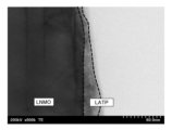
- FIG. It is a scanning transmission electron microscope image of Example 1 of the present invention, (a) represents the vicinity of the interface between the oxide active material and the coating layer, and (b) represents an enlarged region A of (a). It is a scanning transmission electron microscope image of Comparative Example 1 of the present invention.
- a lithium ion secondary battery 1 includes a positive electrode 2, a negative electrode 3, a non-aqueous electrolyte 5, and a separator 6, as shown in FIG. An external load 7 is connected.
- the positive electrode 2 is formed by stacking a positive electrode composite active material layer 11 on a positive electrode current collector 10, and is an intercalation electrode into which lithium ions can be intercalated and deintercalated.
- the positive electrode composite active material layer 11 contains a positive electrode composite active material 20, a conductive aid, and a binder.
- the negative electrode 3 is formed by stacking a negative electrode active material layer 13 on a negative electrode current collector 12, and is an intercalation electrode into which lithium ions can be intercalated and deintercalated.
- the negative electrode active material layer 13 contains a negative electrode active material 21, a conductive aid, and a binder.
- the positive electrode composite active material 20 is a coated positive electrode active material in which the surface of the oxide active material 30 is coated with the coating layer 31 .
- the oxide active material 30 is a lithium ion conductive active material, and has an average lithium desorption/insertion potential of 4.5 V or more with respect to the deposition potential of Li (also indicated as vs. Li + /Li)5. It is preferably 0 V or less. That is, the oxide active material 30 preferably has an operating potential of 4.5 V or more and 5.0 V or less based on lithium metal.
- the potential of lithium ion insertion/extraction reaction (hereinafter also referred to as voltage) (vs. Li + /Li) is, for example, the charge/discharge of a half-cell using the oxide active material 30 as the working electrode and the lithium metal as the counter electrode.
- the plateau with the lowest voltage value may be 4.5 V (vs. Li + /Li) or more, and the plateau with the highest voltage value is 5.0 V (vs. Li + / Li) or less.
- the oxide active material 30 is not particularly limited, a spinel-type lithium manganese oxide represented by the following formula (1) is preferable.
- x and y respectively satisfy 0 ⁇ x ⁇ 0.2 and 0 ⁇ y ⁇ 0.8
- M is Al, Mg, Zn, Ni, Co, Fe, Ti, Cu, and Cr. At least one selected from the group consisting of
- the particle diameter of the oxide active material 30 is not particularly limited, but the median diameter d50 is preferably 5 ⁇ m or more, more preferably 10 ⁇ m or more, and even more preferably 20 ⁇ m or more. Within this range, the difference from the particle size of the coating layer 31 can be ensured, and the coating of the coating layer 31 is facilitated.
- the median diameter d50 of the oxide active material 30 is preferably 100 ⁇ m or less, more preferably 80 ⁇ m or less, even more preferably 50 ⁇ m or less, and particularly preferably 30 ⁇ m or less.
- the coating layer 31 is composed of a lithium ion conductive oxide containing phosphorus as an element, and is preferably composed of an intercalation material that functions alone as a positive electrode active material.
- the lithium ion conductive oxide used in the coating layer 31 of the present embodiment is a lithium phosphate-based lithium ion conductive oxide represented by the following formula (1).
- LiaAbDcPO4 ( 1 ) (In the above formula (1), a, b, and c satisfy 0.9 ⁇ a ⁇ 1.1, 0 ⁇ b ⁇ 1, 0 ⁇ c ⁇ 1, 0.9 ⁇ b + c ⁇ 1.1, and A is at least one selected from the group consisting of Co, Mn, Ni, Fe, Cu and Cr, and D is Mg, Ca, Sr, Ba, Ti, Zn, B, Al, Ga, In, Si, Ge, Sc and at least one selected from the group consisting of Y.)
- the lithium ion conductive oxide forming the coating layer 31 preferably has an average particle diameter of 30 nm or more and 500 nm or less calculated using the X-ray small angle scattering method.
- the median diameter d50 of the oxide active material 30 is preferably 100 or more and 10000 or less, and more preferably 300 or more and 5000 or less when the average particle diameter of the lithium ion conductive oxide constituting the coating layer 31 is 1. more preferably 500 or more and 2000 or less, and particularly preferably 1000 or less.
- the coating of the lithium ion conductive oxide on the oxide active material 30 is preferred over the aggregation of the lithium ion conductive oxides and the formation of aggregates of the oxide active material 30 and the lithium ion conductive oxide. becomes dominant, and the lithium ion conductive oxide can easily cover the surface of the oxide active material 30 to form the coating layer 31 .
- the coating layer 31 is preferably 0.5 parts by mass or more, more preferably 1 part by mass or more, and even more preferably 2 parts by mass or more with respect to 100 parts by mass of the oxide active material 30. .
- the coating layer 31 is preferably 10 parts by mass or less, more preferably 5 parts by mass or less, and even more preferably 4 parts by mass or less with respect to 100 parts by mass of the oxide active material 30. .
- the coating layer 31 constitutes a continuous layer that closely covers the surface shape of the oxide active material 30 .
- the thickness of the coating layer 31 is thinner than the average particle size of the lithium ion conductive oxide, preferably 20 nm or less, more preferably 15 nm or less.
- the thickness of the coating layer 31 is preferably 5 nm or more. Within this range, it is possible to suppress the amount of gas generated while suppressing resistance loss in the coating layer 31 .
- Coating layer 31 is preferably amorphous in a range of 2 nm from the interface with oxide active material 30 from the viewpoint of reducing the interfacial resistance between oxide active material 30 and coating layer 31 . 90% or more of the region of the coating layer 31 is preferably amorphous, and 95% or more of the region is preferably amorphous.
- Lithium titanate is preferably used as the negative electrode active material 21 from the viewpoint that lithium deposition is less likely to occur and safety is improved.
- lithium titanates lithium titanate having a spinel structure is particularly preferable for the negative electrode active material 21 because the expansion and contraction of the active material in the reaction of intercalation and deintercalation of lithium ions is small.
- Lithium titanate may contain, for example, trace amounts of elements other than lithium and titanium, such as Nb.
- the conductive aid is not particularly limited, but a carbon material is preferable.
- the carbon material is preferably at least one selected from natural graphite, artificial graphite, vapor-grown carbon fiber, carbon nanotube, acetylene black, ketjen black, and furnace black.
- the amount of the conductive aid contained in the positive electrode 2 is preferably 1 part by weight or more and 30 parts by weight or less with respect to 100 parts by weight of the positive electrode composite active material 20 .
- the amount of the conductive aid contained in the negative electrode 3 is preferably 1 part by weight or more and 30 parts by weight or less with respect to 100 parts by weight of the negative electrode active material 21 .
- the binder is not particularly limited, but for both the positive electrode 2 and the negative electrode 3, for example, from the group consisting of polyvinylidene fluoride (PVdF), polytetrafluoroethylene (PTFE), styrene-butadiene rubber, polyimide, and derivatives thereof At least one selected can be used.
- PVdF polyvinylidene fluoride
- PTFE polytetrafluoroethylene
- styrene-butadiene rubber polyimide
- derivatives thereof At least one selected can be used.
- the binder is preferably dissolved or dispersed in a non-aqueous solvent or water for ease of production of the positive electrode 2 and the negative electrode 3 .
- Non-aqueous solvents include, but are not limited to, N-methyl-2-pyrrolidone (NMP), dimethylformamide, dimethylacetamide, methyl ethyl ketone, methyl acetate, ethyl acetate, and tetrahydrofuran.
- NMP N-methyl-2-pyrrolidone
- dimethylformamide dimethylacetamide
- methyl ethyl ketone methyl acetate
- ethyl acetate tetrahydrofuran.
- a dispersant and a thickener may be added to these.
- the amount of the binder contained in the positive electrode 2 is preferably 1 part by weight or more and 30 parts by weight or less with respect to 100 parts by weight of the positive electrode composite active material 20 .
- the amount of the binder contained in the negative electrode 3 is preferably 1 part by weight or more and 30 parts by weight or less with respect to 100 parts by weight of the negative electrode active material 21 .
- the current collectors 10 and 12 are not particularly limited, but are preferably made of aluminum or an aluminum alloy because they are stable under the positive electrode reaction atmosphere and the negative electrode reaction atmosphere, and are JIS standard 1030, 1050, 1085, 1N90, 1N99. High-purity aluminum represented by, for example, is more preferable.
- the current collectors 10 and 12 may also be made of a metal other than aluminum (copper, SUS, nickel, titanium, and alloys thereof) coated with a metal that does not react with the potentials of the positive electrode 2 and negative electrode 3 .
- the non-aqueous electrolytic solution 5 is not particularly limited, but may be a non-aqueous electrolytic solution in which a solute is dissolved in a non-aqueous solvent, a gel electrolyte in which a polymer is impregnated with a non-aqueous electrolytic solution in which a solute is dissolved in a non-aqueous solvent, or the like. can be used.
- the non-aqueous solvent preferably contains a cyclic aprotic solvent and/or a chain aprotic solvent.
- cyclic aprotic solvents include cyclic carbonates, cyclic esters, cyclic sulfones and cyclic ethers.
- chain aprotic solvent a chain carbonate, a chain carboxylic acid ester, a chain ether, and a solvent generally used as a solvent for non-aqueous electrolytes, such as acetonitrile, may be used.
- aprotic solvents include dimethyl carbonate, methyl ethyl carbonate, diethyl carbonate, dipropyl carbonate, methyl propyl carbonate, ethylene carbonate, propylene carbonate, butylene carbonate, ⁇ -butyl lactone, 1,2-dimethoxy Ethane, sulfolane, dioxolane, methyl propionate, and the like can be used. These solvents may be used singly or in combination of two or more kinds. is preferably used.
- dimethyl carbonate, methyl ethyl carbonate, diethyl carbonate, dipropyl carbonate, and methyl propyl carbonate have high stability at high temperatures and high lithium conductivity at low temperatures. It is preferable to mix one or more of the chain carbonates exemplified in (1) with one or more of the cyclic compounds exemplified by ethylene carbonate, propylene carbonate, butylene carbonate, and ⁇ -butyl lactone.
- Particularly preferred is a mixture of one or more chain carbonates exemplified by dimethyl carbonate, methylethyl carbonate and diethyl carbonate and one or more cyclic carbonates exemplified by ethylene carbonate, propylene carbonate and butylene carbonate.
- the solute used in the non-aqueous electrolyte 5 is not particularly limited, but examples include LiClO 4 , LiBF 4 , LiPF 6 , LiAsF 6 , LiCF 3 SO 3 , LiBOB (Lithium Bis (Oxalato) Borate), LiN(SO 2 CF 3 ) 2 and the like are preferable because they are easily dissolved in a solvent.
- the non-aqueous electrolyte 5 may further contain a vinyl group-containing cyclic siloxane such as 2,4,6,8-tetravinyl-2,4,6,8-tetramethylcyclotetrasiloxane (4VC4S) as an additive. good.
- a vinyl group-containing cyclic siloxane such as 2,4,6,8-tetravinyl-2,4,6,8-tetramethylcyclotetrasiloxane (4VC4S) as an additive. good.
- the non-aqueous electrolyte 5 may be included in the positive electrode 2, the negative electrode 3, and the separator 6 in advance, or after winding or laminating the separator 6 between the positive electrode 2 side and the negative electrode 3 side. may be added.
- the separator 6 is placed between the positive electrode 2 and the negative electrode 3, and may have any structure as long as it is insulating and can contain the non-aqueous electrolytic solution 5. As shown in FIG. Examples of the separator 6 include nylon, cellulose, polysulfone, polyethylene, polypropylene, polybutene, polyacrylonitrile, polyimide, polyamide, polyethylene terephthalate, and woven fabrics, nonwoven fabrics, microporous membranes, etc. of composites of two or more thereof. .
- the separator 6 may contain various plasticizers, antioxidants, and flame retardants, or may be coated with metal oxide or the like.
- the method for manufacturing the lithium ion secondary battery 1 of the present embodiment mainly includes an active material forming step for forming the positive electrode composite active material 20, a positive electrode forming step for forming the positive electrode 2, and a negative electrode forming step for forming the negative electrode 3. and a secondary battery assembling process for assembling the positive electrode 2, the negative electrode 3, and the non-aqueous electrolyte 5.
- the negative electrode forming process and the secondary battery assembling process are the same as the conventional processes, so the description is omitted. do.
- the lithium ion conductive oxide is pulverized by a pulverizing device such as a ball mill to form lithium ion conductive oxide particles (pulverization step).
- the lithium ion conductive oxide is a phosphorus-containing lithium ion conductive oxide similar to that of the coating layer 31 described above, and can be selected from materials similar to those of the coating layer 31 described above.
- the lithium ion conductive oxide before the pulverization step is phosphate compound particles having an olivine-type crystal structure, and the lithium ion conductive oxide particles after pulverization partially have a crystal structure. Destroyed and completely or partially amorphous.
- XRD X-ray diffraction
- the lithium ion conductive oxide particles preferably have a BET specific surface area of 20 m 2 /g or more and 80 m 2 /g or less.
- the lithium ion conductive oxide particles preferably have a BET specific surface area equivalent diameter (dBET) of 30 nm or more, more preferably 50 nm or more.
- the lithium ion conductive oxide particles preferably have a BET specific surface area equivalent diameter (dBET) of 500 nm or less, more preferably 450 nm or less.
- the lithium ion conductive oxide particles (phosphate-based compound particles) pulverized in a pulverization step are dispersed in a dispersion solvent to form a fine particle fluid (fine particle fluid forming step).
- the dispersion solvent used at this time is preferably one or a plurality of alcohol solutions, and more preferably ethanol from the viewpoint of volatility and safety.
- the particulate fluid formed at this time is a transparent sol in a sol state, and is an electrolytic sol having fluidity.
- the oxide active material A coating layer 31 is formed on the surface of the oxide active material 30 by a mechanical coating method for mechanically contacting the material 30 and the lithium ion conductive oxide in the fine particle fluid.
- the particulate fluid is ground into the oxide active material 30 by a grinding device such as a grinding mill to form a ground material (ground material forming step).
- the treatment temperature in the grinding device is preferably 5° C. or higher, more preferably 8° C. or higher, and even more preferably 10° C. or higher.
- the treatment temperature in the grinding device is preferably 120° C. or less, more preferably 100° C. or less, further preferably 80° C. or less, and even more preferably 70° C. or less.
- the temperature is preferably 50° C. or lower, and particularly preferably 50° C. or lower.
- the treatment time in the grinding device at this time is preferably 5 minutes or longer, more preferably 10 minutes or longer.
- the processing time in the grinding device at this time is preferably 90 minutes or less, more preferably 60 minutes or less.
- the atmosphere in the grinding device is preferably an inert gas atmosphere or an air atmosphere.
- the ground material is heat-treated to remove the dispersion solvent from the ground material to form the positive electrode composite active material 20 (removal step).
- the heat treatment temperature at this time is preferably over 50° C., more preferably 100° C. or higher, even more preferably 300° C. or higher, and particularly preferably 350° C. or higher. If the heat treatment temperature is lower than 50° C., the adhesion between the oxide active material 30 and the coating layer 31 becomes insufficient, and the coating layer 31 may peel off during charging and discharging of the battery, leading to deterioration of the long-term reliability of the battery. . On the other hand, if the heat treatment temperature is too high, the crystal structure of the coating layer 31 may change, the Li ion conductivity may decrease, and the battery may not charge and discharge normally. Therefore, the heat treatment temperature is preferably less than 600.degree. C., and more preferably 500.degree.
- the heat treatment time is preferably 30 minutes or longer, more preferably 1 hour or longer. Although the upper limit of the heat treatment time is not particularly limited, it is, for example, 3 hours or less. The above is the active material forming step.
- the positive electrode forming step is performed.
- the positive electrode composite active material 20 obtained in the active material forming step is mixed with a conductive aid and a binder to prepare a positive electrode mixture, and the positive electrode mixture is applied to the positive electrode current collector 10 ( positive electrode coating step).
- the positive electrode current collector 10 coated with the positive electrode mixture is dried to form the positive electrode 2 (positive electrode drying step).
- the above is the positive electrode forming process.
- the positive electrode 2 formed by the positive electrode forming process described above is assembled together with the negative electrode 3 formed by the negative electrode forming process and the non-aqueous electrolyte 5 in the same manner as in the prior art to complete the lithium ion secondary battery 1 .
- the coating layer 31 uniformly covers the oxide active material 30, so the area in contact with the non-aqueous electrolyte 5 is reduced and gas generation can be suppressed. Further, even if the non-aqueous electrolyte 5 and the additive are partially decomposed, the decomposed product can fill the gaps in the coating of the coating layer 31 to form a good film, so further decomposition of the non-aqueous electrolyte 5 can be suppressed. It becomes possible.
- the oxide active material 30 is composed of a lithium manganese oxide having a spinel crystal structure
- the coating layer 31 is a phosphate-based material that can be used as a positive electrode active material. Composed of compounds. Therefore, lithium ion insertion/extraction reactions tend to occur smoothly.
- the positive electrode composite active material 20 of the present embodiment since the vicinity of the interface between the coating layer 31 and the oxide active material 30 is amorphous, the volume change of the oxide active material 30 with the progress of charging and discharging is The amorphous portion of the coating layer 31 functions as a buffer even if a crack occurs. Therefore, cracking and peeling of the coating layer 31 are less likely to occur.
- the fine particle fluid in which the lithium ion conductive oxide particles are dispersed in the dispersion solvent is ground into the oxide active material 30, and the Since the heat treatment is applied, a thin coating layer 31 of good quality can be formed on the surface of the oxide active material 30 while maintaining the amorphous state.
- each constituent member can be freely replaced or added between the embodiments.
- Example 1 (i) Preparation of positive electrode First, lithium iron phosphate (LiFePO 4 , hereinafter also referred to as LFP) powder having a surface area of 9.5 m 2 /g and a median diameter of 1.5 ⁇ m was mixed with a predetermined amount of ethanol as a solvent, Planetary ball milling was performed for 3 hours using zirconia balls with a diameter of 0.5 mm. After removing the zirconia balls from the treated mixture with a sieve, the mixture was dried at 120° C. to remove the ethanol. As a result, LFP fine powder having a BET value (BET surface area) of 20 m 2 /g to 80 m 2 /g was obtained. Next, the LFP fine powder was mixed with ethanol to obtain a slurry (fine particle fluid) in which the LFP fine powder was dispersed in ethanol with a solid content of 16.4% by weight.
- LFP lithium iron phosphate
- LNMO Spinel-type lithium nickel manganate
- a grinding mill manufactured by Hosokawa Micron Corporation, product name: Nobilta
- a rotor load power 1.5 kW. was added in two batches so that the amount of added was 4.5 g (equivalent to 2.4 wt %).
- the rotor rotation speed was kept in the range of 2600 rpm to 3000 rpm, and the mixture was treated at room temperature for 10 minutes in an air atmosphere to obtain an LNMO surface-coated with LFP (hereinafter also referred to as surface-coated LNMO).
- the resulting surface-coated LNMO was heat-treated at 350° C. for 1 hour to obtain a positive electrode composite active material.
- PVdF polyvinylidene fluoride
- a slurry was prepared by dispersing the mixture in N-methyl-2-pyrrolidone (NMP).
- NMP N-methyl-2-pyrrolidone
- the binder used was prepared in an N-methyl-2-pyrrolidone (NMP) solution having a solid concentration of 5% by weight, and NMP was further added to adjust the viscosity so as to facilitate the later-described coating.
- the positive electrode was produced by vacuum drying at 170°C.
- the negative electrode was produced by vacuum-drying at 170°C.
- Two sheets of aluminum laminate films were prepared as exterior materials, and after forming a recess for the battery portion and a recess for the gas trapping portion by pressing, the electrode laminate was put therein.
- the outer periphery leaving a space for non-aqueous electrolyte injection is heat-sealed at 180 ° C.
- ethylene carbonate, propylene carbonate, and ethyl methyl carbonate are removed from the unsealed portion on a volume basis, ethylene carbonate/propylene carbonate/ LiPF 6 was dissolved in a solvent mixed with ethyl methyl carbonate at a ratio of 15/15/70 at a ratio of 1 mol/L, and after adding a nonaqueous electrolyte, the unsealed portion was heated to 180°C for 7 seconds while reducing the pressure. It was heat sealed with The obtained battery was subjected to constant current charging at a current value corresponding to 0.2 C until the battery voltage reached the final voltage of 3.4 V, and charging was stopped. Then, after standing in an environment of 60° C.
- Example 2 was obtained in the same manner as in Example 1, except that the coating amount of LFP fine powder was adjusted to 6.9 g (equivalent to 3.6 wt %) in the preparation of the positive electrode.
- Li 1.3 Al 0.3 Ti 1.7 (PO 4 ) 3 (hereinafter also referred to as LATP) was prepared as an active material for the positive electrode by the following method.
- a predetermined amount of Li 2 CO 3 , AlPO 4 , TiO 2 , NH 4 H 2 PO 4 and ethanol as a solvent were mixed as starting materials, and subjected to planetary ball mill treatment at 150 G for 1 hour using zirconia balls with a diameter of 3 mm. . After removing the zirconia balls from the treated mixture with a sieve, the mixture was dried at 120° C. to remove the ethanol. Thereafter, treatment was performed at 800° C. for 2 hours to obtain LATP powder.
- Comparative Example 1 was prepared in the same manner as in Example 1 except that the LATP powder described above was used.
- Comparative Example 2 was prepared in the same manner as in Comparative Example 1, except that the coating amount of the LATP fine powder was adjusted to 6.9 g (equivalent to 3.6 wt %) in the preparation of the positive electrode.
- Comparative Example 3 was prepared in the same manner as in Example 1, except that LNMO without surface coating was used in the preparation of the positive electrode.
- Comparative Example 4 was prepared in the same manner as in Example 1, except that the surface-coated LNMO was heat-treated at 600° C. for 1 hour in the preparation of the positive electrode.
- Comparative Example 5 was prepared in the same manner as in Example 1, except that the surface-coated LNMO was heat-treated at 50° C. for 1 hour in the preparation of the positive electrode.
- Comparative Example 7 (i) In the preparation of the positive electrode, LFP fine powder was dispersed in ethanol, and LNMO was added while stirring so that the weight of the LFP fine powder was 3%, and stirring was continued for 1 hour. Thereafter, ethanol was removed under reduced pressure and then heated at 120° C. to further remove ethanol to obtain LNMO surface-coated with LFP. The resulting surface-coated LNMO was heat treated at 350° C. for 1 hour. Comparative Example 7 was obtained in the same manner as Example 1, except that the surface-coated LNMO was used to prepare the positive electrode.
- the weight of the lithium ion secondary battery was measured with an electronic balance.
- the weight in water was measured using a hydrometer (manufactured by Alpha Mirage Co., Ltd., product number: MDS-3000), and the buoyancy was calculated by taking the difference between these weights.
- the volume of the lithium ion secondary battery was calculated by dividing this buoyancy by the density of water (1.0 g/cm 3 ).
- the amount of generated gas was calculated by comparing the volume after aging (that is, the volume after charging by applying voltage and then discharging) and the volume after the following cycle characteristic evaluation. Those with a gas generation amount of 5 ml or less were judged to be good.
- the stability of the cycle characteristics was evaluated by taking the discharge capacity at the 500th time assuming that the discharge capacity at the first time was 100, as a discharge capacity retention rate (%). A discharge capacity retention rate of 90% or more at the 500th cycle was judged as good, and a discharge capacity retention rate of less than 90% was judged as unsatisfactory.
- Example 1 and 2 and Comparative Examples 1-3 are shown in Table 1, and the evaluation results of Example 1 and Comparative Examples 4-7 are shown in Table 2. Further, a scanning transmission electron microscope image of Example 1 is shown in FIG. 2, and a scanning transmission electron microscope image of Comparative Example 1 is shown in FIG.
- Examples 1 and 2 using LFP as the coating layer had comparable capacity retention rates and a small amount of gas generation compared to Comparative Examples 1 and 2 using LATP as the coating layer. became.
- the thickness of the coating layer was thicker than the particle size before grinding, whereas Examples 1 and 2 using LFP as the coating layer In , the thickness of the coating layer was thinner than the particle size before milling.
- the amount of gas generated was less than in Comparative Example 3 in which LNMO was not coated with LFP, and the capacity retention ratio was high.
- the gas generation amount was 10 ml or less and the capacity retention rate was 90% or more, and the gas generation amount was compared to other Comparative Examples 4 to 7 coated with LFP. was small and the capacity retention ratio was high.
- the heat treatment temperature is preferably in the range of more than 50° C. and less than 600° C., and more preferably 100° C. or more and 500° C. or less. It was suggested.
- Example 1 compared to Comparative Example 6, in which the pulverization time in the pulverization step was short and the particle size was large, the amount of generated gas was small and the capacity retention ratio was high. That is, in Example 1 with a large BET surface area, compared to Comparative Example 6 with a small BET surface area, the amount of generated gas was small and the capacity retention ratio was high. From this result, it was suggested that the amount of generated gas can be reduced and the capacity retention rate can be increased by reducing the size of the particle size of the LFP fine powder and increasing the surface area.
- Example 1 in which LFP was coated by mechanical coating, produced a smaller amount of generated gas and a higher capacity retention rate than Comparative Example 7, in which LFP was coated by evaporation to dryness. From this result, it was suggested that by coating the LFP with mechanical coating, the amount of generated gas can be reduced and the capacity retention rate can be improved.
- Example 1 As shown in FIG. 2(a), a continuous LFP layer of 5 nm to 15 nm was confirmed on the surface of the LNMO. That is, the coating layer of Example 1 was a thin and uniform layer, and the difference between the maximum thickness and the minimum thickness was within 15 nm. In LNMO, regular lattice fringes were confirmed as shown in FIG. 2(b), suggesting that the spinel crystal structure was maintained. On the other hand, no lattice fringes were observed throughout the LFP, suggesting that it was amorphous at least in the range of 2 nm from the interface with the LNMO.
- the coating layer of Comparative Example 1 has an distorted shape with different thicknesses depending on the position as shown in FIG. It was a layer. This suggests that a thin and uniform layer can be formed by forming the coating layer with LFP.
Landscapes
- Chemical & Material Sciences (AREA)
- Chemical Kinetics & Catalysis (AREA)
- Electrochemistry (AREA)
- General Chemical & Material Sciences (AREA)
- Inorganic Chemistry (AREA)
- Battery Electrode And Active Subsutance (AREA)
Abstract
本発明は、従来に比べて均一な被覆層を備え、非水電解液の分解によるガスの発生を抑制できる正極複合活物質及び正極複合活物質の製造方法を提供する。 酸化物活物質と、酸化物活物質の表面を覆う被覆層を有し、酸化物活物質は、スピネル型の結晶構のリチウムマンガン系酸化物で構成されており、被覆層は、式(1)で表されるリン酸塩系化合物で構成されており、被覆層の厚みは、5nm以上20nm以下である構成とする。 LiaAbDcPO4・・・(1) (式(1)は、a、b、cが0.9<a<1.1、0<b≦1、0≦c<1、0.9<b+c<1.1を満たし、AがCo、Mn、Ni、Fe、Cu及びCrからなる群から選択される少なくとも1種であり、DがMg、Ca、Sr、Ba、Ti、Zn、B、Al、Ga、In、Si、Ge、Sc、及びYからなる群から選択される少なくとも1種である。)
Description
本発明は、正極複合活物質及び正極複合活物質の製造方法に関する。
従来から、リチウムイオン二次電池は、電気自動車の車載用電源等の用途として注目されており、更なる高エネルギー密度化が求められている。
リチウムイオン二次電池の正極活物質としては、例えば、リチウムニッケルマンガン酸化物(Lithium Nickel Manganese Oxide)(以下、LNMOともいう)がある(例えば、特許文献1)。
LNMOは、作動電圧がリチウムの析出電位基準で4.7Vであり、正極活物質材料として使用されている従来のリチウムインサーション材料(例えば、コバルト酸リチウムは4V)に比べて高く、高エネルギー密度化に向けて期待されている。
リチウムイオン二次電池の正極活物質としては、例えば、リチウムニッケルマンガン酸化物(Lithium Nickel Manganese Oxide)(以下、LNMOともいう)がある(例えば、特許文献1)。
LNMOは、作動電圧がリチウムの析出電位基準で4.7Vであり、正極活物質材料として使用されている従来のリチウムインサーション材料(例えば、コバルト酸リチウムは4V)に比べて高く、高エネルギー密度化に向けて期待されている。
しかしながら、LNMOは、作動電圧が高く、酸化雰囲気下で反応が進行するため、非水電解液の一部が分解してガスが発生してしまう問題がある。
そこで、特許文献2では、LNMOの表面にLATPを被覆することで、LNMOが直接非水電解液に晒されなくし、ガスの発生量を抑制することが可能とされている。
そこで、特許文献2では、LNMOの表面にLATPを被覆することで、LNMOが直接非水電解液に晒されなくし、ガスの発生量を抑制することが可能とされている。
しかしながら、特許文献2の二次電池について検討したところ、被覆層が形成される際にLNMOの表面上にナノ粒子が凝集して被覆層が形成されるため、局所的に厚みが異なる部分が生じ、安定して均一な被覆層が形成されにくい問題があった。
そこで、本発明は、従来に比べて均一な被覆層を備え、非水電解液の分解によるガスの発生を抑制できる正極複合活物質及び正極複合活物質の製造方法を提供することを目的とする。
上記した課題を解決するための本発明の一つの様相は、非水電解液を電解質とするリチウムイオン二次電池の正極の一部を構成する正極複合活物質であって、酸化物活物質と、前記酸化物活物質の表面を覆う被覆層を有し、前記酸化物活物質は、スピネル型の結晶構造を有するリチウムマンガン系酸化物で構成されており、前記被覆層は、下記の式(1)で表されるリン酸塩系化合物で構成されており、前記被覆層の厚みは、5nm以上20nm以下である、正極複合活物質である。
LiaAbDcPO4・・・(1)
(前記式(1)は、a、b、cが0.9<a<1.1、0<b≦1、0≦c<1、0.9<b+c<1.1を満たし、AがCo、Mn、Ni、Fe、Cu及びCrからなる群から選択される少なくとも1種であり、DがMg、Ca、Sr、Ba、Ti、Zn、B、Al、Ga、In、Si、Ge、Sc、及びYからなる群から選択される少なくとも1種である。)
LiaAbDcPO4・・・(1)
(前記式(1)は、a、b、cが0.9<a<1.1、0<b≦1、0≦c<1、0.9<b+c<1.1を満たし、AがCo、Mn、Ni、Fe、Cu及びCrからなる群から選択される少なくとも1種であり、DがMg、Ca、Sr、Ba、Ti、Zn、B、Al、Ga、In、Si、Ge、Sc、及びYからなる群から選択される少なくとも1種である。)
ここで「被覆層の厚み」は、例えば、透過型電子顕微鏡(TEM)や走査型電子顕微鏡(SEM)などの顕微鏡によって直接観察し、10nm以上離れた特定の3点以上の測定点における厚みを算術平均することで求めることができる。
本様相によれば、スピネル型の結晶構造を有するリチウムマンガン系酸化物で構成された酸化物活物質の表面を上記の式(1)を満たすリン酸塩系化合物で構成された被覆層が覆う。その結果、従来に比べて、酸化物活物質が非水電解液に接することを抑制でき、表面での誘電分極も緩和できるので、非水電解液が分解されることによるガスの発生を抑制できる。
本様相によれば、上記の式(1)を満たすリン酸塩系化合物で構成された被覆層を備えるため、被覆層が従来に比べて均一な層となりやすい。
本様相によれば、被覆層の厚みが薄くてもガスの発生を抑制でき、リン酸塩系化合物による抵抗損失を抑制できる。
本様相によれば、上記の式(1)を満たすリン酸塩系化合物で構成された被覆層を備えるため、被覆層が従来に比べて均一な層となりやすい。
本様相によれば、被覆層の厚みが薄くてもガスの発生を抑制でき、リン酸塩系化合物による抵抗損失を抑制できる。
好ましい様相は、前記被覆層は、前記酸化物活物質との界面から2nmの範囲において非晶質である。
ここでいう「非晶質」とは、透過型電子顕微鏡にて50万倍に拡大して観察したときに規則的に配列した格子縞が見えない状態をいう。
本様相によれば、被覆層の酸化物活物質との界面近傍が非晶質となっているため、酸化物活物質と被覆層との間の界面抵抗を小さくできる。
好ましい様相は、前記酸化物活物質は、下記の式(2)で表される化合物である。
Li1+xMyMn2-x-yO4・・・(2)
前記式(2)は、x、yがそれぞれ0≦x≦0.2、0<y≦0.8を満たし、MがAl、Mg、Zn、Ni、Co、Fe、Ti、Cu、及びCrよりなる群から選ばれる少なくとも1種である。
Li1+xMyMn2-x-yO4・・・(2)
前記式(2)は、x、yがそれぞれ0≦x≦0.2、0<y≦0.8を満たし、MがAl、Mg、Zn、Ni、Co、Fe、Ti、Cu、及びCrよりなる群から選ばれる少なくとも1種である。
本発明の一つの様相は、非水電解液を電解質とするリチウムイオン二次電池の正極の一部を構成し、酸化物活物質と、前記酸化物活物質の表面を覆う被覆層を有する正極複合活物質の製造方法であって、リン酸塩系化合物粒子を分散溶媒に分散させ、微粒子流動体を形成する微粒子流動体形成工程と、前記微粒子流動体を酸化物活物質に摩砕させて摩砕物を形成する摩砕物形成工程と、前記摩砕物を熱処理し、前記分散溶媒を除去し、前記被覆層を形成する除去工程と、を含み、前記リン酸塩系化合物粒子は、前記被覆層の厚み以上の平均粒径を有するものであって、かつ下記の式(1)で表されるリン酸塩系化合物で構成されている、正極複合活物質の製造方法である。
LiaAbDcPO4・・・(1)
(前記式(1)は、a、b、cが0.9<a<1.1、0<b≦1、0≦c<1、0.9<b+c<1.1を満たし、AがCo、Mn、Ni、Fe、Cu及びCrからなる群から選択される少なくとも1種であり、DがMg、Ca、Sr、Ba、Ti、Zn、B、Al、Ga、In、Si、Ge、Sc、及びYからなる群から選択される少なくとも1種である。)
LiaAbDcPO4・・・(1)
(前記式(1)は、a、b、cが0.9<a<1.1、0<b≦1、0≦c<1、0.9<b+c<1.1を満たし、AがCo、Mn、Ni、Fe、Cu及びCrからなる群から選択される少なくとも1種であり、DがMg、Ca、Sr、Ba、Ti、Zn、B、Al、Ga、In、Si、Ge、Sc、及びYからなる群から選択される少なくとも1種である。)
ここでいう「平均粒径」は、算術平均粒子径を表し、各種方法によって求めることができる。例えば、「平均粒径」は、透過型電子顕微鏡(TEM)や走査型電子顕微鏡(SEM)などの顕微鏡によって直接観察し、算術平均径によって求めてもよいし、比表面積計測法(BET法)によって比表面積から算出して求めてもよいし、X線回折法(XRD)や、動的光散乱法(DLS)、レーザー回折・散乱法(LD)などによって計測して求めてもよい。以下、同様とする。
本様相によれば、酸化物活物質の表面に良質で薄い被覆層を形成でき、従来に比べて非水電解液の分解によるガスの発生を抑制できる正極複合活物質を製造できる。
好ましい様相は、前記微粒子流動体形成工程よりも前にオリビン型の結晶構造を有するリン酸塩系化合物を粉砕し、前記リン酸塩系化合物粒子を形成する粉砕工程を含むことである。
本様相によれば、リン酸塩系化合物粒子を非晶質にしやすい。
好ましい様相は、前記リン酸塩系化合物粒子は、平均粒径が30nm以上500nm以下である。
好ましい様相は、前記被覆層の厚みは、5nm以上20nm以下である。
好ましい様相は、前記摩砕物を100℃以上500℃以下の温度で熱処理し、前記分散溶媒を除去することである。
本発明の正極複合活物質によれば、従来に比べて均一な被覆層を備え、非水電解液の分解によるガスの発生を抑制できる。
本発明の正極複合活物質の製造方法によれば、酸化物活物質の表面に良質で薄い被覆層を形成でき、従来に比べて非水電解液の分解によるガスの発生を抑制できる正極複合活物質を製造できる。
本発明の正極複合活物質の製造方法によれば、酸化物活物質の表面に良質で薄い被覆層を形成でき、従来に比べて非水電解液の分解によるガスの発生を抑制できる正極複合活物質を製造できる。
以下、本発明の実施形態について詳細に説明する。
本発明の第1実施形態のリチウムイオン二次電池1は、図1のように、正極2と、負極3と、非水電解液5と、セパレータ6を備えており、正極2と負極3に外部負荷7が接続されている。
正極2は、正極集電体10上に正極複合活物質層11が積層されたものであり、リチウムイオンが挿入・脱離が可能なインターカレーション電極である。
正極複合活物質層11は、正極複合活物質20、導電助剤、及びバインダーを有している。
負極3は、負極集電体12上に負極活物質層13が積層されたものであり、リチウムイオンが挿入・脱離が可能なインターカレーション電極である。
負極活物質層13は、負極活物質21、導電助剤、及びバインダーを有している。
正極2は、正極集電体10上に正極複合活物質層11が積層されたものであり、リチウムイオンが挿入・脱離が可能なインターカレーション電極である。
正極複合活物質層11は、正極複合活物質20、導電助剤、及びバインダーを有している。
負極3は、負極集電体12上に負極活物質層13が積層されたものであり、リチウムイオンが挿入・脱離が可能なインターカレーション電極である。
負極活物質層13は、負極活物質21、導電助剤、及びバインダーを有している。
正極複合活物質20は、酸化物活物質30の表面に被覆層31が被覆された被覆正極活物質である。
<酸化物活物質30>
酸化物活物質30は、リチウムイオン伝導性活物質であり、リチウムの脱離及び挿入の平均電位がLiの析出電位に対して(vs.Li+/Liとも示す)、4.5V以上5.0V以下であることが好ましい。すなわち、酸化物活物質30は、単体でのリチウム金属基準での作動電位が4.5V以上5.0V以下であることが好ましい。
リチウムイオン挿入・脱離反応の電位(以下、電圧ともいう)(vs.Li+/Li)は、例えば、酸化物活物質30を用いた動作極、リチウム金属を対極とした半電池の充放電特性を測定し、プラトー開始時、及び終了時の電圧値を読み取ることによって求めることができる。プラトーが2箇所以上あった場合は、もっとも低い電圧値のプラトーが4.5V(vs.Li+/Li)以上であればよく、もっとも高い電圧値のプラトーが5.0V(vs.Li+/Li)以下であればよい。
酸化物活物質30は、特に限定されないが、下記式(1)で表されるスピネル型のリチウムマンガン系酸化物が好ましい。
Li1+xMyMn2-x-yO4・・・(1)
前記式(1)中、x、yはそれぞれ0≦x≦0.2、0<y≦0.8を満たし、MはAl、Mg、Zn、Ni、Co、Fe、Ti、Cu、及びCrよりなる群から選ばれる少なくとも1種である。
Li1+xMyMn2-x-yO4・・・(1)
前記式(1)中、x、yはそれぞれ0≦x≦0.2、0<y≦0.8を満たし、MはAl、Mg、Zn、Ni、Co、Fe、Ti、Cu、及びCrよりなる群から選ばれる少なくとも1種である。
上記式(1)の中でも、MがNiであるNi置換リチウムマンガン化合物(LNMO)が好ましく、特にx=0、y=0.5、M=Niである、すなわちLiNi0.5Mn1.5O4が充放電サイクルの安定性効果が高いことから特に好ましい。
酸化物活物質30の粒径は、特に限定されないが、メジアン径d50が5μm以上であることが好ましく、10μm以上であることがより好ましく、20μm以上であることがさらに好ましい。
この範囲であれば、被覆層31の粒径との差を確保でき、被覆層31の被覆が容易となる。
また酸化物活物質30は、メジアン径d50が100μm以下であることが好ましく、80μm以下であることがより好ましく、50μm以下であることがさらに好ましく、30μm以下であることが特に好ましい。
この範囲であれば、被覆層31の粒径との差を確保でき、被覆層31の被覆が容易となる。
また酸化物活物質30は、メジアン径d50が100μm以下であることが好ましく、80μm以下であることがより好ましく、50μm以下であることがさらに好ましく、30μm以下であることが特に好ましい。
<被覆層31>
被覆層31は、元素としてリンを含有したリチウムイオン伝導性酸化物で構成されており、単独で正極活物質として機能するインターカレーション材料で構成されていることが好ましい。
本実施形態の被覆層31で使用されるリチウムイオン伝導性酸化物は、下記の式(1)で表されるリチウムリン酸系のリチウムイオン伝導性酸化物である。
LiaAbDcPO4・・・(1)
(前記式(1)は、a、b、cが0.9<a<1.1、0<b≦1、0≦c<1、0.9<b+c<1.1を満たし、AがCo、Mn、Ni、Fe、Cu及びCrからなる群から選択される少なくとも1種であり、DがMg、Ca、Sr、Ba、Ti、Zn、B、Al、Ga、In、Si、Ge、Sc、及びYからなる群から選択される少なくとも1種である。)
被覆層31を構成するリチウムイオン伝導性酸化物は、X線小角散乱法を用いて算出される平均粒径が30nm以上500nm以下であることが好ましい。
酸化物活物質30のメジアン径d50は、被覆層31を構成するリチウムイオン伝導性酸化物の平均粒径を1としたときに、100以上10000以下であることが好ましく、300以上5000以下であることがより好ましく、500以上2000以下であることがさらに好ましく、1000以下であることが特に好ましい。
この範囲であれば、リチウムイオン伝導性酸化物同士の凝集や酸化物活物質30とリチウムイオン伝導性酸化物の凝集体の生成よりも酸化物活物質30へのリチウムイオン伝導性酸化物の被覆が支配的となり、リチウムイオン伝導性酸化物が酸化物活物質30の表面を容易に被覆し、被覆層31を形成できる。
この範囲であれば、リチウムイオン伝導性酸化物同士の凝集や酸化物活物質30とリチウムイオン伝導性酸化物の凝集体の生成よりも酸化物活物質30へのリチウムイオン伝導性酸化物の被覆が支配的となり、リチウムイオン伝導性酸化物が酸化物活物質30の表面を容易に被覆し、被覆層31を形成できる。
100質量部の酸化物活物質30に対して被覆層31は、0.5質量部以上であることが好ましく、1質量部以上であることがより好ましく、2質量部以上であることがさらに好ましい。
また、100質量部の酸化物活物質30に対して被覆層31は、10質量部以下であることが好ましく、5質量部以下であることがより好ましく、4質量部以下であることがさらに好ましい。
また、100質量部の酸化物活物質30に対して被覆層31は、10質量部以下であることが好ましく、5質量部以下であることがより好ましく、4質量部以下であることがさらに好ましい。
被覆層31は、酸化物活物質30の表面形状を緻密に覆った連続した層を構成している。
被覆層31の厚みは、リチウムイオン伝導性酸化物の平均粒径よりも薄く、20nm以下であることが好ましく、15nm以下であることがより好ましい。
被覆層31の厚みは、5nm以上であることが好ましい。
この範囲であれば、被覆層31での抵抗損失を抑制しつつ、ガスの発生量を抑制できる。
被覆層31の厚みは、リチウムイオン伝導性酸化物の平均粒径よりも薄く、20nm以下であることが好ましく、15nm以下であることがより好ましい。
被覆層31の厚みは、5nm以上であることが好ましい。
この範囲であれば、被覆層31での抵抗損失を抑制しつつ、ガスの発生量を抑制できる。
被覆層31は、酸化物活物質30と被覆層31との間の界面抵抗を小さくする観点から、酸化物活物質30との界面から2nmの範囲において非晶質であることが好ましい。
被覆層31は、90%以上の領域が非晶質であることが好ましく、95%以上の領域が非晶質であることが好ましい。
被覆層31は、90%以上の領域が非晶質であることが好ましく、95%以上の領域が非晶質であることが好ましい。
<負極活物質21>
負極活物質21は、リチウム析出が起きにくく安全性が向上する観点からチタン酸リチウムを使用することが好ましい。
負極活物質21は、チタン酸リチウムの中でも、リチウムイオンの挿入・脱離の反応における活物質の膨張収縮が小さい点から、スピネル構造のチタン酸リチウムが特に好ましい。
チタン酸リチウムには、例えば、Nbなどのリチウム、チタン以外の元素が微量含まれていてもよい。
負極活物質21は、リチウム析出が起きにくく安全性が向上する観点からチタン酸リチウムを使用することが好ましい。
負極活物質21は、チタン酸リチウムの中でも、リチウムイオンの挿入・脱離の反応における活物質の膨張収縮が小さい点から、スピネル構造のチタン酸リチウムが特に好ましい。
チタン酸リチウムには、例えば、Nbなどのリチウム、チタン以外の元素が微量含まれていてもよい。
<導電助剤>
導電助剤としては、特に限定されないが、炭素材料が好ましい。
炭素材料は、天然黒鉛、人造黒鉛、気相成長炭素繊維、カーボンナノチューブ、アセチレンブラック、ケッチェンブラック、及びファーネスブラックから選ばれる少なくとも1種であることが好ましい。
正極2に含まれる導電助剤の量は、正極複合活物質20を100重量部に対して1重量部以上30重量部以下であることが好ましい。
負極3に含まれる導電助剤の量は、負極活物質21を100重量部に対して1重量部以上30重量部以下であることが好ましい。
上記範囲であれば、電極2,3の導電性を確保しつつ、バインダーとの接着性が維持され、集電体10,12との接着性を十分に得ることができる。
<バインダー>
バインダーは、特に限定されないが、正極2及び負極3のいずれについても、例えば、ポリフッ化ビニリデン(PVdF)、ポリテトラフルオロエチレン(PTFE)、スチレン-ブタジエンゴム、ポリイミド、及びそれらの誘導体からなる群より選ばれる少なくとも1種を用いることができる。
バインダーは、正極2及び負極3の作製しやすさから、非水溶媒又は水に溶解又は分散されていることが好ましい。
非水溶媒は、特に限定されないが、例えば、N-メチル-2-ピロリドン(NMP)、ジメチルホルムアミド、ジメチルアセトアミド、メチルエチルケトン、酢酸メチル、酢酸エチル、及びテトラヒドロフランなどを挙げることができる。これらに分散剤、増粘剤を加えてもよい。
正極2に含まれるバインダーの量は、正極複合活物質20を100重量部に対して1重量部以上30重量部以下であることが好ましい。
負極3に含まれるバインダーの量は、負極活物質21を100重量部に対して、好ましくは1重量部以上30重量部以下であることが好ましい。
上記範囲であれば、活物質20,21と導電助材との接着性が維持され集電体10,12との接着性を十分に得ることができる。
<集電体10,12>
集電体10,12は、特に限定されないが、正極反応雰囲気下及び負極反応雰囲気下で安定であることから、アルミニウム又はアルミニウム合金であることが好ましく、JIS規格1030、1050、1085、1N90、1N99等に代表される高純度アルミニウムであることがより好ましい。
集電体10,12は、アルミニウム以外の金属(銅、SUS、ニッケル、チタン、及びそれらの合金)の表面に正極2及び負極3の電位で反応しない金属を被覆したものも用いることもできる。
集電体10,12は、特に限定されないが、正極反応雰囲気下及び負極反応雰囲気下で安定であることから、アルミニウム又はアルミニウム合金であることが好ましく、JIS規格1030、1050、1085、1N90、1N99等に代表される高純度アルミニウムであることがより好ましい。
集電体10,12は、アルミニウム以外の金属(銅、SUS、ニッケル、チタン、及びそれらの合金)の表面に正極2及び負極3の電位で反応しない金属を被覆したものも用いることもできる。
<非水電解液5>
非水電解液5は、特に限定されないが、非水溶媒に溶質を溶解させた非水電解液、非水溶媒に溶質を溶解させた非水電解液を高分子に含浸させたゲル電解質などを用いることができる。
非水電解液5は、特に限定されないが、非水溶媒に溶質を溶解させた非水電解液、非水溶媒に溶質を溶解させた非水電解液を高分子に含浸させたゲル電解質などを用いることができる。
非水溶媒としては、環状の非プロトン性溶媒及び/又は鎖状の非プロトン性溶媒を含むことが好ましい。
環状の非プロトン性溶媒としては、環状カーボネート、環状エステル、環状スルホン及び環状エーテルなどが例示される。
鎖状の非プロトン性溶媒としては、鎖状カーボネート、鎖状カルボン酸エステル、鎖状エーテル、及びアセトニトリルなどの一般的に非水電解質の溶媒として用いられる溶媒を用いてもよい。
より具体的には、非プロトン性溶媒としては、ジメチルカーボネート、メチルエチルカーボネート、ジエチルカーボネート、ジプロピルカーボネート、メチルプロピルカーボネート、エチレンカーボネート、プロピレンカーボネート、ブチレンカーボネート、γ-ブチルラクトン、1,2-ジメトキシエタン、スルホラン、ジオキソラン、プロピオン酸メチルなどを用いることができる。
これら溶媒は、1種類で用いてもよいし、2種類以上混合して用いてもよいが、後述の溶質の溶解させやすさ、リチウムイオンの伝導性の高さから、2種類以上混合した溶媒を用いることが好ましい。
非プロトン性溶媒として2種類以上混合する場合、高温時の安定性が高く、且つ低温時のリチウム伝導性が高いことから、ジメチルカーボネート、メチルエチルカーボネート、ジエチルカーボネート、ジプロピルカーボネート、及びメチルプロピルカーボネートに例示される鎖状カーボネートのうち1種類以上と、エチレンカーボネート、プロピレンカーボネート、ブチレンカーボネート、及びγ-ブチルラクトンに例示される環状化合物のうち1種類以上との混合が好ましい。
ジメチルカーボネート、メチルエチルカーボネート、及びジエチルカーボネートに例示される鎖状カーボネートのうち1種類以上と、エチレンカーボネート、プロピレンカーボネート、ブチレンカーボネートに例示される環状カーボネートのうち1種類以上との混合が特に好ましい。
ジメチルカーボネート、メチルエチルカーボネート、及びジエチルカーボネートに例示される鎖状カーボネートのうち1種類以上と、エチレンカーボネート、プロピレンカーボネート、ブチレンカーボネートに例示される環状カーボネートのうち1種類以上との混合が特に好ましい。
非水電解液5に使用される溶質は、特に限定されないが、例えば、LiClO4、LiBF4、LiPF6、LiAsF6、LiCF3SO3、LiBOB(Lithium Bis (Oxalato) Borate)、LiN(SO2CF3)2などは溶媒に溶解しやすいことから好ましい。
非水電解液5は、さらに2,4,6,8-テトラビニル-2,4,6,8-テトラメチルシクロテトラシロキサン(4VC4S)等のビニル基含有環状シロキサンを添加剤として添加してもよい。
非水電解液5は、あらかじめ正極2、負極3、及びセパレータ6に含ませてもよいし、正極2側と負極3側との間にセパレータ6を配置したものを倦回、あるいは積層した後に添加してもよい。
<セパレータ6>
セパレータ6は、正極2と負極3との間に設置され、絶縁性かつ非水電解液5を含むことができる構造であればよい。
セパレータ6は、例えば、ナイロン、セルロース、ポリスルホン、ポリエチレン、ポリプロピレン、ポリブテン、ポリアクリロニトリル、ポリイミド、ポリアミド、ポリエチレンテレフタラート、及びそれらを2種類以上複合したものの織布、不織布、微多孔膜などが挙げられる。
セパレータ6は、正極2と負極3との間に設置され、絶縁性かつ非水電解液5を含むことができる構造であればよい。
セパレータ6は、例えば、ナイロン、セルロース、ポリスルホン、ポリエチレン、ポリプロピレン、ポリブテン、ポリアクリロニトリル、ポリイミド、ポリアミド、ポリエチレンテレフタラート、及びそれらを2種類以上複合したものの織布、不織布、微多孔膜などが挙げられる。
セパレータ6には、各種可塑剤、酸化防止剤、難燃剤が含まれてもよいし、金属酸化物等が被覆されていてもよい。
続いて、本実施形態のリチウムイオン二次電池1の製造方法について説明する。
本実施形態のリチウムイオン二次電池1の製造方法は、主に、正極複合活物質20を形成する活物質形成工程と、正極2を形成する正極形成工程と、負極3を形成する負極形成工程と、正極2と負極3と非水電解液5を組み立てる二次電池組立工程によって構成されており、負極形成工程と二次電池組立工程については、従来の工程と同様であるため、説明を省略する。
活物質形成工程では、まずボールミル等の粉砕装置によって、リチウムイオン伝導性酸化物を粉砕し、リチウムイオン伝導性酸化物粒子を形成する(粉砕工程)。
このとき、リチウムイオン伝導性酸化物は、上記した被覆層31と同様のリンを含むリチウムイオン伝導性酸化物であり、上記した被覆層31と同様の材料から選択できる。
このとき、粉砕工程前のリチウムイオン伝導性酸化物は、オリビン型の結晶構造を有したリン酸塩系化合物粒子であり、粉砕後のリチウムイオン伝導性酸化物粒子は、部分的に結晶構造が破壊され、全部又は部分的にアモルファス(非晶質)となっている。
本実施形態では、リチウムイオン伝導性酸化物粒子をX線回折(XRD)法で測定したときに、粉砕前には表れていたリチウムイオン伝導性酸化物粒子の固有の結晶ピークがハローパターンによって確認されない状態となっている。
このとき、リチウムイオン伝導性酸化物粒子は、BET比表面積が20m2/g以上80m2/g以下であることが好ましい。
リチウムイオン伝導性酸化物粒子は、BET比表面積換算径(dBET)が30nm以上であることが好ましく、50nm以上であることがより好ましい。
また、リチウムイオン伝導性酸化物粒子は、BET比表面積換算径(dBET)が500nm以下であることが好ましく、450nm以下であることがより好ましい。
これらの範囲であれば、酸化物活物質30の表面を均一に被覆することができ、緻密な被覆層31を形成できる。
なお、BET比表面積換算径(dBET)は、JIS Z8830(2013)に規定された方法に従って、窒素吸着法一点法により、窒素吸着BET比表面積を求め、dBET=6/(密度×BET比表面積)の式により求められる粒径である。
続いて、粉砕工程で粉砕し、微粒子化したリチウムイオン伝導性酸化物粒子(リン酸塩系化合物粒子)を分散溶媒に分散させ、微粒子流動体を形成する(微粒子流動体形成工程)。
このときに使用される分散溶媒は、一又は複数のアルコール溶液であることが好ましく、揮発性や安全性の点からエタノールであることがより好ましい。
このときに形成される微粒子流動体は、透明であってゾル状態の透明ゾルであり、流動性を有した電解質ゾルである。
このときに形成される微粒子流動体は、透明であってゾル状態の透明ゾルであり、流動性を有した電解質ゾルである。
続いて、せん断力、圧縮力、衝突力、及び遠心力の少なくとも1種のエネルギーを酸化物活物質30及び/又は被覆層31を構成するリチウムイオン伝導性酸化物に付与しつつ、酸化物活物質30と微粒子流動体内のリチウムイオン伝導性酸化物を機械的に接触させるメカニカルコーティング法によって、酸化物活物質30の表面に被覆層31を形成する。
本実施形態では、摩砕式ミル等の摩砕装置によって、微粒子流動体を酸化物活物質30に摩砕させ、摩砕物を形成する(摩砕物形成工程)。
本実施形態では、摩砕式ミル等の摩砕装置によって、微粒子流動体を酸化物活物質30に摩砕させ、摩砕物を形成する(摩砕物形成工程)。
このときの摩砕装置での処理温度は、5℃以上であることが好ましく、8℃以上であることがより好ましく、10℃以上であることがさらに好ましい。
このときの摩砕装置での処理温度は、120℃以下であることが好ましく、100℃以下であることがより好ましく、80℃以下であることがさらに好ましく、70℃以下であることがよりさらに好ましく、50℃以下であることが特に好ましい。
このときの摩砕装置での処理時間は、5分以上であることが好ましく、10分以上であることがより好ましい。
このときの摩砕装置での処理時間は、90分以下であることが好ましく、60分以下であることがより好ましい。
このときの摩砕装置での雰囲気は、不活性ガス雰囲気下又は空気雰囲気下であることが好ましい。
このときの摩砕装置での処理温度は、120℃以下であることが好ましく、100℃以下であることがより好ましく、80℃以下であることがさらに好ましく、70℃以下であることがよりさらに好ましく、50℃以下であることが特に好ましい。
このときの摩砕装置での処理時間は、5分以上であることが好ましく、10分以上であることがより好ましい。
このときの摩砕装置での処理時間は、90分以下であることが好ましく、60分以下であることがより好ましい。
このときの摩砕装置での雰囲気は、不活性ガス雰囲気下又は空気雰囲気下であることが好ましい。
続いて、摩砕物に対して熱処理を行い、摩砕物から分散溶媒を除去し、正極複合活物質20を形成する(除去工程)。
このときの熱処理温度は、50℃超過であることが好ましく、100℃以上であることがより好ましく、300℃以上であることがさらに好ましく、350℃以上であることが特に好ましい。
熱処理温度が50℃を下回ると、酸化物活物質30と被覆層31の密着性が不十分となり、電池の充放電時に被覆層31が剥離し、電池の長期信頼性の低下に繋がるおそれがある。
一方、熱処理温度が高くなりすぎると、被覆層31の結晶構造が変化し、Liイオン伝導度が低下して電池の充放電が正常に行われなくなる場合がある。そのため、熱処理温度は600℃未満であることが好ましく、被覆層31の結晶化を抑制する観点から500℃以下であることがより好ましい。
熱処理時間は、30分以上であることが好ましく、1時間以上であることがより好ましい。熱処理時間の上限は、特に限定されないが、例えば3時間以下である。
以上が活物質形成工程である。
活物質形成工程が終了すると、続いて正極形成工程に移行する。
正極形成工程では、まず、活物質形成工程によって得られた正極複合活物質20を導電助剤及びバインダーと混合して正極合剤を作成し、正極合剤を正極集電体10に塗布する(正極塗布工程)。
正極形成工程では、まず、活物質形成工程によって得られた正極複合活物質20を導電助剤及びバインダーと混合して正極合剤を作成し、正極合剤を正極集電体10に塗布する(正極塗布工程)。
続いて、正極合剤が塗布された正極集電体10を乾燥させて正極2が形成される(正極乾燥工程)。
以上が正極形成工程である。
以上が正極形成工程である。
上記した正極形成工程によって形成された正極2が、従来と同様、負極形成工程によって形成された負極3と非水電解液5とともに組み立てられて、リチウムイオン二次電池1が完成する。
本実施形態の正極複合活物質20によれば、被覆層31が酸化物活物質30を均一に被覆しているので、非水電解液5と接する面積が小さくなりガス発生が抑制できる。また、非水電解液5や添加剤が一部分解する場合でも、分解物が被覆層31の被覆の隙間を埋め良好な被膜を形成できるため、さらなる非水電解液5の分解を抑制することが可能となる。
本実施形態の正極複合活物質20によれば、酸化物活物質30としてスピネル型の結晶構造を有するリチウムマンガン系酸化物で構成され、被覆層31として正極活物質として使用可能なリン酸塩系化合物で構成されている。そのため、リチウムイオンの挿入・脱離反応がスムーズに起こりやすい。
本実施形態の正極複合活物質20によれば、被覆層31の酸化物活物質30との界面近傍が非晶質となっているので、充放電の進行に伴う酸化物活物質30の体積変化が生じても被覆層31の非晶質部分が緩衝体として機能する。そのため、被覆層31の割れ、剥がれが生じにくい。
本実施形態の正極複合活物質20によれば、リチウムイオン伝導性酸化物粒子を分散溶媒に分散させた微粒子流動体を酸化物活物質30に摩砕させ、100℃以上500℃以下の温度で熱処理を加えるので、非晶質を維持した状態で酸化物活物質30の表面に良質で薄い被覆層31を形成できる。
上記した実施形態は、本発明の技術的範囲に含まれる限り、各実施形態間で各構成部材を自由に置換や付加できる。
以下、実施例により本発明を具体的に説明する。なお、本発明は、以下の実施例に限定されるものではなく、その要旨を変更しない範囲で適宜変更して実施できる。
(実施例1)
(i)正極の作製
まず、表面積が9.5m2/g、メジアン径が1.5μmのリン酸鉄リチウム(LiFePO4、以下、LFPともいう)粉末に溶剤となるエタノールを所定量混合し、直径0.5mmのジルコニア球を用いて3時間遊星ボールミル処理を行った。処理後の混合物からジルコニア球を篩で取り除いた後、120℃で乾燥してエタノールを除去した。これにより、BET値(BET表面積)が20m2/g~80m2/gのLFP微粉末を得た。次に、前記LFP微粉末とエタノールを混合し、固形分が16.4重量%の、エタノールにLFP微粉末が分散したスラリー(微粒子流動体)を得た。
(i)正極の作製
まず、表面積が9.5m2/g、メジアン径が1.5μmのリン酸鉄リチウム(LiFePO4、以下、LFPともいう)粉末に溶剤となるエタノールを所定量混合し、直径0.5mmのジルコニア球を用いて3時間遊星ボールミル処理を行った。処理後の混合物からジルコニア球を篩で取り除いた後、120℃で乾燥してエタノールを除去した。これにより、BET値(BET表面積)が20m2/g~80m2/gのLFP微粉末を得た。次に、前記LFP微粉末とエタノールを混合し、固形分が16.4重量%の、エタノールにLFP微粉末が分散したスラリー(微粒子流動体)を得た。
正極の活物質として、メジアン径が5μmのスピネル型のニッケルマンガン酸リチウム(LiNi0.5Mn1.5O4、以下、LNMOともいう)を用いた。
LNMO30gを摩砕式ミル(ホソカワミクロン株式会社製、製品名:ノビルタ)に投入し、クリアランス0.6mm、ローター負荷動力1.5kW、2600rpmで回転させながら、LFP微粉末のエタノール分散スラリーをLFP微粉末の添加量が4.5g(2.4wt%相当)となるように二回に分けて投入した。その後、前記ローター回転数を2600rpm~3000rpmの範囲に保って空気雰囲気下、室温で10分間処理し、LFPで表面を被覆したLNMO(以下、表面被覆LNMOともいう)を得た。得られた表面被覆LNMOを350℃で1時間熱処理し、正極複合活物質を得た。
LNMO30gを摩砕式ミル(ホソカワミクロン株式会社製、製品名:ノビルタ)に投入し、クリアランス0.6mm、ローター負荷動力1.5kW、2600rpmで回転させながら、LFP微粉末のエタノール分散スラリーをLFP微粉末の添加量が4.5g(2.4wt%相当)となるように二回に分けて投入した。その後、前記ローター回転数を2600rpm~3000rpmの範囲に保って空気雰囲気下、室温で10分間処理し、LFPで表面を被覆したLNMO(以下、表面被覆LNMOともいう)を得た。得られた表面被覆LNMOを350℃で1時間熱処理し、正極複合活物質を得た。
得られた正極複合活物質、導電助剤としてのアセチレンブラック、及びバインダーとしてのポリフッ化ビニリデン(PVdF)を、それぞれ固形分濃度で90重量部、6重量部、及び4重量部含む混合物を作成し、当該混合物をN-メチル-2-ピロリドン(NMP)に分散させたスラリーを作製した。なお、前記バインダーは固形分濃度5重量%のN-メチル-2-ピロリドン(NMP)溶液に調整したものを使用し、後述の塗工をしやすいように、さらにNMPを加えて粘度調整した。
前記スラリーを20μmのアルミニウム箔に塗工した後に、120℃のオーブンで乾燥させた。この操作をアルミ箔の両面に対して実施した後、さらに170℃で真空乾燥することによって正極を作製した。
(ii)負極の作製
負極活物質として、スピネル型のチタン酸リチウム(Li4Ti5O12、以下、LTOともいう)を用いた。前記LTO、導電助材としてのアセチレンブラック、及びバインダーとしてのポリフッ化ビニリデン(PVdF)を、それぞれ固形分濃度で100重量部、5重量部、及び5重量部を含む混合物を作製し、当該混合物をN-メチル-2-ピロリドン(NMP)に分散させたスラリーを作製した。なお、バインダーは固形分濃度5重量%のNMP溶液に調製したものを使用し、後述の塗工をしやすいように、さらにNMPを加えて粘度調整した。
負極活物質として、スピネル型のチタン酸リチウム(Li4Ti5O12、以下、LTOともいう)を用いた。前記LTO、導電助材としてのアセチレンブラック、及びバインダーとしてのポリフッ化ビニリデン(PVdF)を、それぞれ固形分濃度で100重量部、5重量部、及び5重量部を含む混合物を作製し、当該混合物をN-メチル-2-ピロリドン(NMP)に分散させたスラリーを作製した。なお、バインダーは固形分濃度5重量%のNMP溶液に調製したものを使用し、後述の塗工をしやすいように、さらにNMPを加えて粘度調整した。
前記スラリーを20μmのアルミニウム箔に塗工した後に、120℃のオーブンで乾燥させた。この操作をアルミ箔の両面に対して実施した後、さらに170℃で真空乾燥することによって負極を作製した。
(iii)リチウムイオン二次電池の作製
上記(i)及び(ii)で作製した正極及び負極と、20μmのポリプロピレン製のセパレータを用いて、以下の手順で電池を作製した。
まず初めに、正極及び負極を80℃で12時間、減圧乾燥した。次に、負極/セパレータ/正極の順に正極を15枚、負極を16枚使用して積層した。最外層はどちらもセパレータとなるようにした。次に、両端の正極及び負極にアルミニウムタブを振動溶着させた。
上記(i)及び(ii)で作製した正極及び負極と、20μmのポリプロピレン製のセパレータを用いて、以下の手順で電池を作製した。
まず初めに、正極及び負極を80℃で12時間、減圧乾燥した。次に、負極/セパレータ/正極の順に正極を15枚、負極を16枚使用して積層した。最外層はどちらもセパレータとなるようにした。次に、両端の正極及び負極にアルミニウムタブを振動溶着させた。
外装材となる二枚のアルミラミネートフィルムを準備し、プレスにより電池部となる窪みとガス捕集部となる窪みを形成後、前記電極積層体を入れた。
非水電解質注液用のスペースを残した外周部を180℃×7秒でヒートシールし、未シール箇所から、エチレンカーボネート、プロピレンカーボネート、及びエチルメチルカーボネートを、体積基準でエチレンカーボネート/プロピレンカーボネート/エチルメチルカーボネート=15/15/70の割合で混合した溶媒に、LiPF6を1mol/Lとなる割合で溶解させ、非水電解質を入れた後に、減圧しながら未シール箇所を180℃×7秒でヒートシールした。
得られた電池を0.2C相当の電流値で電池電圧が終止電圧3.4Vに到達するまで定電流充電を行い、充電を停止した。その後、60℃の環境で24時間静置した後、0.2C相当の電流値で定電流放電を行い、電池電圧が2.5Vに達した時点で放電を停止した。放電停止後、ガス捕集部に溜まったガスを抜き取り、再シールを行った。以上の操作により、評価用のリチウムイオン二次電池を作製した。
(実施例2)
(i)正極の作製において、LFP微粉末の被覆量が6.9g(3.6wt%相当)になるように調整したこと以外は実施例1と同様にして、これを実施例2とした。
(i)正極の作製において、LFP微粉末の被覆量が6.9g(3.6wt%相当)になるように調整したこと以外は実施例1と同様にして、これを実施例2とした。
(比較例1)
(i)正極の作製において、正極の活物質として、Li1.3Al0.3Ti1.7(PO4)3(以下、LATPともいう)を以下の方法で調製した。
出発原料として、Li2CO3、AlPO4、TiO2、NH4H2PO4、溶剤となるエタノールを所定量混合し、直径3mmのジルコニア球を用いて150Gで1時間遊星ボールミル処理を行った。処理後の混合物からジルコニア球を篩で取り除いた後、120℃で乾燥してエタノールを除去した。その後、800℃で2時間処理を行い、LATP粉末を得た。
上記したLATP粉末を使用したこと以外は、実施例1と同様にしてこれを比較例1とした。
(i)正極の作製において、正極の活物質として、Li1.3Al0.3Ti1.7(PO4)3(以下、LATPともいう)を以下の方法で調製した。
出発原料として、Li2CO3、AlPO4、TiO2、NH4H2PO4、溶剤となるエタノールを所定量混合し、直径3mmのジルコニア球を用いて150Gで1時間遊星ボールミル処理を行った。処理後の混合物からジルコニア球を篩で取り除いた後、120℃で乾燥してエタノールを除去した。その後、800℃で2時間処理を行い、LATP粉末を得た。
上記したLATP粉末を使用したこと以外は、実施例1と同様にしてこれを比較例1とした。
(比較例2)
(i)正極の作製において、LATP微粉末の被覆量が6.9g(3.6wt%相当)になるように調整したこと以外は比較例1と同様にして、これを比較例2とした。
(i)正極の作製において、LATP微粉末の被覆量が6.9g(3.6wt%相当)になるように調整したこと以外は比較例1と同様にして、これを比較例2とした。
(比較例3)
(i)正極の作製において、表面被覆を行わないLNMOを使用する以外は、実施例1と同様にして、これを比較例3とした。
(i)正極の作製において、表面被覆を行わないLNMOを使用する以外は、実施例1と同様にして、これを比較例3とした。
(比較例4)
(i)正極の作製において、表面被覆LNMOを600℃、1時間の条件で熱処理したこと以外は実施例1と同様にして、これを比較例4とした。
(i)正極の作製において、表面被覆LNMOを600℃、1時間の条件で熱処理したこと以外は実施例1と同様にして、これを比較例4とした。
(比較例5)
(i)正極の作製において、表面被覆LNMOを50℃、1時間で熱処理したこと以外は実施例1と同様にして、これを比較例5とした。
(i)正極の作製において、表面被覆LNMOを50℃、1時間で熱処理したこと以外は実施例1と同様にして、これを比較例5とした。
(比較例6)
(i)正極の作製において、リン酸鉄リチウム粉末に溶剤となるエタノールを所定量混合し、0.5時間遊星ボールミル処理を行ったこと以外は実施例1と同様にして、これを比較例6とした。
(i)正極の作製において、リン酸鉄リチウム粉末に溶剤となるエタノールを所定量混合し、0.5時間遊星ボールミル処理を行ったこと以外は実施例1と同様にして、これを比較例6とした。
(比較例7)
(i)正極の作製において、LFP微粉末をエタノールに分散させ、撹拌しながら、LFP微粉末の重量が3%となるようにLNMOを添加し、1時間撹拌を続けた。その後、減圧によりエタノールを除去した後、120℃で加熱して更にエタノールを除去し、LFPで表面被覆したLNMOを得た。得られた表面被覆LNMOを350℃で1時間熱処理した。この表面被覆LNMOを使用して正極を調製する以外は実施例1と同様にして、これを比較例7とした。
(i)正極の作製において、LFP微粉末をエタノールに分散させ、撹拌しながら、LFP微粉末の重量が3%となるようにLNMOを添加し、1時間撹拌を続けた。その後、減圧によりエタノールを除去した後、120℃で加熱して更にエタノールを除去し、LFPで表面被覆したLNMOを得た。得られた表面被覆LNMOを350℃で1時間熱処理した。この表面被覆LNMOを使用して正極を調製する以外は実施例1と同様にして、これを比較例7とした。
(ガス発生量測定)
各実施例1,2及び比較例1~7におけるサイクル特性評価の前後のリチウムイオン二次電池のガス発生量の評価は、アルキメデス法、すなわちリチウムイオン二次電池の浮力を用いて評価した。ガス発生量の評価は下記の通りに行った。
各実施例1,2及び比較例1~7におけるサイクル特性評価の前後のリチウムイオン二次電池のガス発生量の評価は、アルキメデス法、すなわちリチウムイオン二次電池の浮力を用いて評価した。ガス発生量の評価は下記の通りに行った。
最初に、リチウムイオン二次電池の重量を電子天秤で測定した。次に、比重計(アルファミラージュ株式会社製、品番:MDS-3000)を用いて水中での重量を測定し、これら重量の差をとることによって浮力を算出した。この浮力を水の密度(1.0g/cm3)で除算することによって、リチウムイオン二次電池の体積を算出した。エージング後の体積(すなわち、電圧を印加して充電してから放電させた後の体積)と、下記のサイクル特性評価後の体積を比較することによって、発生したガス量を算出した。ガス発生量が5ml以下のものを良好と判断した。
(リチウムイオン二次電池のサイクル特性評価)
各実施例1,2及び比較例1~7で作製したリチウムイオン二次電池を、充放電装置(HJ1005SD8、北斗電工株式会社製)に接続し、サイクル運転を行った。60℃の環境下で、1.0C相当の電流値で電池電圧が終止電圧3.4Vに到達するまで定電流充電を行い、充電を停止した。続いて1.0C相当の電流値で定電流放電を行い、電池電圧が2.5Vに達した時点で放電を停止した。これを1サイクルとして充放電を繰り返した。サイクル特性の安定性は、1回目の放電容量を100としたときの500回目の放電容量を、放電容量維持率(%)として評価した。500回目の放電容量維持率が90%以上を良好、90%未満を不良とした。
各実施例1,2及び比較例1~7で作製したリチウムイオン二次電池を、充放電装置(HJ1005SD8、北斗電工株式会社製)に接続し、サイクル運転を行った。60℃の環境下で、1.0C相当の電流値で電池電圧が終止電圧3.4Vに到達するまで定電流充電を行い、充電を停止した。続いて1.0C相当の電流値で定電流放電を行い、電池電圧が2.5Vに達した時点で放電を停止した。これを1サイクルとして充放電を繰り返した。サイクル特性の安定性は、1回目の放電容量を100としたときの500回目の放電容量を、放電容量維持率(%)として評価した。500回目の放電容量維持率が90%以上を良好、90%未満を不良とした。
(走査透過型電子顕微鏡観察)
正極複合活物質を樹脂包埋し、シリコンウェハに挟んだ後、イオンミリング加工装置(Gatan社製、Model 691)によって薄片加工し、薄くなった部分に対して走査透過型電子顕微鏡(株式会社日立ハイテク製、HD-2700)によって観察を行った。
正極複合活物質を樹脂包埋し、シリコンウェハに挟んだ後、イオンミリング加工装置(Gatan社製、Model 691)によって薄片加工し、薄くなった部分に対して走査透過型電子顕微鏡(株式会社日立ハイテク製、HD-2700)によって観察を行った。
各実施例1,2及び比較例1~3の評価結果を表1に示し、実施例1及び比較例4~7の評価結果を表2に示す。また、実施例1の走査透過型電子顕微鏡画像を図2に示し、比較例1の走査透過型電子顕微鏡画像を図3に示す。


被覆層としてLFPを使用した実施例1,2は、表1のように、被覆層としてLATPを使用した比較例1,2に比べて、容量維持率が同程度であり、ガス発生量が小さくなった。
また、被覆層としてLATPを使用した比較例1,2では、摩砕前の粒径に比べて被覆層の厚みが厚くなったのに対して、被覆層としてLFPを使用した実施例1,2では、摩砕前の粒径に比べて被覆層の厚みが薄くなった。
LNMOにLFPを被覆した実施例1,2は、ガス発生量がLNMOにLFPを被覆していない比較例3に比べて少なく、容量維持率が高くなった。
また、被覆層としてLATPを使用した比較例1,2では、摩砕前の粒径に比べて被覆層の厚みが厚くなったのに対して、被覆層としてLFPを使用した実施例1,2では、摩砕前の粒径に比べて被覆層の厚みが薄くなった。
LNMOにLFPを被覆した実施例1,2は、ガス発生量がLNMOにLFPを被覆していない比較例3に比べて少なく、容量維持率が高くなった。
実施例1,2では、表1,表2のように、ガス発生量が10ml以下でかつ容量維持率が90%以上となり、LFPを被覆した他の比較例4~7に比べてガス発生量が少なく、容量維持率が高い結果となった。
熱処理温度が350℃の実施例1では、熱処理温度が600℃の比較例4や熱処理温度が50℃の比較例5に比べて発生ガス量が少なく、容量維持率も高い結果となった。
この結果から、ガス発生量の抑制と容量維持率の向上の観点から、熱処理温度は50℃超過600℃未満の範囲であることが好ましく、100℃以上500℃以下であることがより好ましいことが示唆された。
この結果から、ガス発生量の抑制と容量維持率の向上の観点から、熱処理温度は50℃超過600℃未満の範囲であることが好ましく、100℃以上500℃以下であることがより好ましいことが示唆された。
実施例1では、粉砕工程での粉砕時間が短く粒径が大きい比較例6に比べて、発生ガス量が少なく、容量維持率も高い結果となった。すなわち、BET表面積が大きい実施例1では、BET表面積が小さい比較例6に比べて、発生ガス量が少なく、容量維持率も高い結果となった。
この結果から、LFP微粉末の粒径の大きさを小さくし、表面積を大きくすることで発生ガス量が少なくでき、容量維持率も高くできることが示唆された。
この結果から、LFP微粉末の粒径の大きさを小さくし、表面積を大きくすることで発生ガス量が少なくでき、容量維持率も高くできることが示唆された。
メカニカルコーティングによってLFPを被覆した実施例1は、蒸発乾固によってLFPを被覆した比較例7に比べて発生ガス量が少なく、容量維持率も高い結果となった。
この結果から、メカニカルコーティングによってLFPを被覆することで発生ガス量が少なくでき、容量維持率を向上できると示唆された。
この結果から、メカニカルコーティングによってLFPを被覆することで発生ガス量が少なくでき、容量維持率を向上できると示唆された。
実施例1では、図2(a)のように、LNMOの表面に連続した5nm~15nmのLFPの層が確認された。すなわち、実施例1の被覆層は、薄く均一な層となっており、最大厚みと最小厚みの差が15nm以内となっていた。
LNMOは、図2(b)のように規則的な格子縞が確認され、スピネル型の結晶構造が維持されていることが示唆された。一方、LFPは、全体にわたって格子縞が確認されず、少なくともLNMOとの界面から2nmの範囲において非晶質であることが示唆された。
また、比較例1の被覆層は、図3のように、位置によって厚さが異なるいびつな形状であるのに対して、実施例1の被覆層は、図2(a)のように薄く均一な層となっていた。
このことから、被覆層をLFPで形成することで薄く均一な層が形成できることが示唆された。
LNMOは、図2(b)のように規則的な格子縞が確認され、スピネル型の結晶構造が維持されていることが示唆された。一方、LFPは、全体にわたって格子縞が確認されず、少なくともLNMOとの界面から2nmの範囲において非晶質であることが示唆された。
また、比較例1の被覆層は、図3のように、位置によって厚さが異なるいびつな形状であるのに対して、実施例1の被覆層は、図2(a)のように薄く均一な層となっていた。
このことから、被覆層をLFPで形成することで薄く均一な層が形成できることが示唆された。
上記の結果をまとめると以下の通りである。
(1)LNMOの表面にLFPを被覆することでLATPを被覆する場合よりもガス発生量を抑制できることがわかった。
(2)LFPを摩砕することで、摩砕前のLFPの粒径に対して摩砕によって形成される被覆層の厚みが薄くなることがわかった。
(3)熱処理温度を調整することで、ガス発生量の抑制と容量維持率の向上が期待できることがわかった。
(4)メカニカルコーティング法、特に摩砕を行うことでガス発生量の抑制と容量維持率の向上が期待できることがわかった。
(5)LFPのLNMOとの界面近傍を非晶質とすることで、ガス発生量の抑制と容量維持率の向上が期待できることがわかった。
(6)LFPの厚みが5nm~20nm程度であっても、十分にガス発生量を抑制でき、十分な容量維持率を確保できることがわかった。
(7)被覆層としてLFPを用いることで薄く均一な層が形成されることが示唆された。
1 リチウムイオン二次電池
2 正極
3 負極
5 非水電解液
10 正極集電体
11 正極複合活物質層
20 正極複合活物質
21 負極活物質
30 酸化物活物質
31 被覆層
2 正極
3 負極
5 非水電解液
10 正極集電体
11 正極複合活物質層
20 正極複合活物質
21 負極活物質
30 酸化物活物質
31 被覆層
Claims (8)
- 非水電解液を電解質とするリチウムイオン二次電池の正極の一部を構成する正極複合活物質であって、
酸化物活物質と、前記酸化物活物質の表面を覆う被覆層を有し、
前記酸化物活物質は、スピネル型の結晶構造を有するリチウムマンガン系酸化物で構成されており、
前記被覆層は、下記の式(1)で表されるリン酸塩系化合物で構成されており、
前記被覆層の厚みは、5nm以上20nm以下である、正極複合活物質。
LiaAbDcPO4・・・(1)
(前記式(1)は、a、b、cが0.9<a<1.1、0<b≦1、0≦c<1、0.9<b+c<1.1を満たし、AがCo、Mn、Ni、Fe、Cu及びCrからなる群から選択される少なくとも1種であり、DがMg、Ca、Sr、Ba、Ti、Zn、B、Al、Ga、In、Si、Ge、Sc、及びYからなる群から選択される少なくとも1種である。) - 前記被覆層は、前記酸化物活物質との界面から2nmの範囲において非晶質である、請求項1に記載の正極複合活物質。
- 前記酸化物活物質は、下記の式(2)で表される化合物である、請求項1又は2に記載の正極複合活物質。
Li1+xMyMn2-x-yO4・・・(2)
前記式(2)は、x、yがそれぞれ0≦x≦0.2、0<y≦0.8を満たし、MがAl、Mg、Zn、Ni、Co、Fe、Ti、Cu、及びCrよりなる群から選ばれる少なくとも1種である。 - 非水電解液を電解質とするリチウムイオン二次電池の正極の一部を構成し、酸化物活物質と、前記酸化物活物質の表面を覆う被覆層を有する正極複合活物質の製造方法であって、
リン酸塩系化合物粒子を分散溶媒に分散させ、微粒子流動体を形成する微粒子流動体形成工程と、
前記微粒子流動体を酸化物活物質に摩砕させて摩砕物を形成する摩砕物形成工程と、
前記摩砕物を熱処理し、前記分散溶媒を除去し、前記被覆層を形成する除去工程と、を含み、
前記リン酸塩系化合物粒子は、前記被覆層の厚み以上の平均粒径を有するものであって、かつ下記の式(1)で表されるリン酸塩系化合物で構成されている、正極複合活物質の製造方法。
LiaAbDcPO4・・・(1)
(前記式(1)は、a、b、cが0.9<a<1.1、0<b≦1、0≦c<1、0.9<b+c<1.1を満たし、AがCo、Mn、Ni、Fe、Cu及びCrからなる群から選択される少なくとも1種であり、DがMg、Ca、Sr、Ba、Ti、Zn、B、Al、Ga、In、Si、Ge、Sc、及びYからなる群から選択される少なくとも1種である。) - 前記微粒子流動体形成工程よりも前にオリビン型の結晶構造を有するリン酸塩系化合物を粉砕し、前記リン酸塩系化合物粒子を形成する粉砕工程を含む、請求項4に記載の正極複合活物質の製造方法。
- 前記リン酸塩系化合物粒子は、平均粒径が30nm以上500nm以下である、請求項4又は5に記載の正極複合活物質の製造方法。
- 前記被覆層の厚みは、5nm以上20nm以下である、請求項4~6のいずれか1項に記載の正極複合活物質の製造方法。
- 前記除去工程では、前記摩砕物を100℃以上500℃以下の温度で熱処理し、前記分散溶媒を除去する、請求項4~7のいずれか1項に記載の正極複合活物質の製造方法。
Applications Claiming Priority (2)
| Application Number | Priority Date | Filing Date | Title |
|---|---|---|---|
| JP2022017263 | 2022-02-07 | ||
| JP2022-017263 | 2022-08-12 |
Publications (1)
| Publication Number | Publication Date |
|---|---|
| WO2023149363A1 true WO2023149363A1 (ja) | 2023-08-10 |
Family
ID=87552403
Family Applications (1)
| Application Number | Title | Priority Date | Filing Date |
|---|---|---|---|
| PCT/JP2023/002566 WO2023149363A1 (ja) | 2022-02-07 | 2023-01-27 | 正極複合活物質及び正極複合活物質の製造方法 |
Country Status (1)
| Country | Link |
|---|---|
| WO (1) | WO2023149363A1 (ja) |
Citations (7)
| Publication number | Priority date | Publication date | Assignee | Title |
|---|---|---|---|---|
| JP2007103339A (ja) * | 2005-09-08 | 2007-04-19 | Sanyo Electric Co Ltd | 非水電解質二次電池 |
| JP2011502332A (ja) * | 2007-10-29 | 2011-01-20 | デジョン イーエム カンパニー リミテッド | リチウム二次電池用正極活物質、その製造方法、これを含むリチウム二次電池の正極及びリチウム二次電池 |
| JP2013191540A (ja) * | 2012-03-13 | 2013-09-26 | Samsung Corning Precision Materials Co Ltd | 正極活物質およびその製造方法並びにこれを利用した2次電池 |
| JP2016170942A (ja) * | 2015-03-12 | 2016-09-23 | トヨタ自動車株式会社 | 固体電池用正極活物質の製造方法 |
| JP2018116856A (ja) * | 2017-01-19 | 2018-07-26 | トヨタ自動車株式会社 | リチウムイオン二次電池用正極活物質 |
| CN112514109A (zh) * | 2018-04-19 | 2021-03-16 | A123系统有限责任公司 | 用于涂层阴极材料的方法和系统以及涂层阴极材料的用途 |
| JP2021136206A (ja) * | 2020-02-28 | 2021-09-13 | 太平洋セメント株式会社 | リチウムイオン二次電池用正極活物質複合体の製造方法 |
-
2023
- 2023-01-27 WO PCT/JP2023/002566 patent/WO2023149363A1/ja active Application Filing
Patent Citations (7)
| Publication number | Priority date | Publication date | Assignee | Title |
|---|---|---|---|---|
| JP2007103339A (ja) * | 2005-09-08 | 2007-04-19 | Sanyo Electric Co Ltd | 非水電解質二次電池 |
| JP2011502332A (ja) * | 2007-10-29 | 2011-01-20 | デジョン イーエム カンパニー リミテッド | リチウム二次電池用正極活物質、その製造方法、これを含むリチウム二次電池の正極及びリチウム二次電池 |
| JP2013191540A (ja) * | 2012-03-13 | 2013-09-26 | Samsung Corning Precision Materials Co Ltd | 正極活物質およびその製造方法並びにこれを利用した2次電池 |
| JP2016170942A (ja) * | 2015-03-12 | 2016-09-23 | トヨタ自動車株式会社 | 固体電池用正極活物質の製造方法 |
| JP2018116856A (ja) * | 2017-01-19 | 2018-07-26 | トヨタ自動車株式会社 | リチウムイオン二次電池用正極活物質 |
| CN112514109A (zh) * | 2018-04-19 | 2021-03-16 | A123系统有限责任公司 | 用于涂层阴极材料的方法和系统以及涂层阴极材料的用途 |
| JP2021136206A (ja) * | 2020-02-28 | 2021-09-13 | 太平洋セメント株式会社 | リチウムイオン二次電池用正極活物質複合体の製造方法 |
Similar Documents
| Publication | Publication Date | Title |
|---|---|---|
| US10263252B2 (en) | Negative electrode for non-aqueous electrolyte secondary battery, and non-aqueous electrolyte secondary battery | |
| US8178238B2 (en) | Positive-electrode active material for lithium-ion secondary battery, positive electrode, manufacturing method thereof, and lithium-ion secondary battery | |
| CN111670511B (zh) | 负极活性材料、包含所述负极活性材料的负极和包含所述负极的锂二次电池 | |
| CN106025191B (zh) | 锂离子二次电池用正极活性物质、锂离子二次电池用正极以及锂离子二次电池 | |
| CN107112499B (zh) | 非水电解质二次电池用负极和非水电解质二次电池 | |
| US8399132B2 (en) | Niobium oxide-containing electrode and lithium battery including the same | |
| WO2013021843A1 (ja) | 硫化物系固体電池 | |
| US10411265B2 (en) | Lithium ion secondary battery and method of manufacturing same | |
| JP5505479B2 (ja) | リチウムイオン二次電池用負極及びその負極を用いたリチウムイオン二次電池 | |
| JP5505480B2 (ja) | リチウムイオン二次電池用負極及びその負極を用いたリチウムイオン二次電池 | |
| JP2016189320A (ja) | リチウムイオン二次電池用正極活物質、リチウムイオン二次電池用正極およびこれを用いたリチウムイオン二次電池 | |
| JP7403908B2 (ja) | 導電材、これを含む電極形成用スラリー、電極及びこれを用いて製造されるリチウム二次電池 | |
| JP2016189321A (ja) | リチウムイオン二次電池用正極活物質、リチウムイオン二次電池用正極およびこれを用いたリチウムイオン二次電池 | |
| JP7358363B2 (ja) | 被覆正極活物質及びリチウムイオン二次電池の製造方法 | |
| US10971726B2 (en) | Lithium ion secondary battery and method for manufacturing lithium ion secondary battery | |
| JP2019164880A (ja) | リチウムイオン二次電池用正極活物質、リチウムイオン二次電池用正極およびこれを用いたリチウムイオン二次電池 | |
| WO2016152716A1 (ja) | リチウムイオン二次電池用負極および二次電池 | |
| US9466837B1 (en) | Battery having negative electrode including amorphous carbon | |
| JP2019160577A (ja) | リチウムイオン二次電池用正極活物質、リチウムイオン二次電池用正極およびリチウムイオン二次電池 | |
| KR101796248B1 (ko) | 리튬이차전지용 양극활물질 및 그 제조방법 | |
| WO2023149363A1 (ja) | 正極複合活物質及び正極複合活物質の製造方法 | |
| WO2023063303A1 (ja) | 正極複合活物質、リチウムイオン二次電池、及びリチウムイオン二次電池の製造方法 | |
| WO2019088171A1 (ja) | リチウムイオン二次電池 | |
| US20240014451A1 (en) | Positive electrode composite active substance, lithium ion secondary battery, composite active substance, method for producing positive electrode composite active substance, and method for producing lithium ion secondary battery | |
| JP2019160576A (ja) | リチウムイオン二次電池用正極活物質、リチウムイオン二次電池用正極およびリチウムイオン二次電池 |
Legal Events
| Date | Code | Title | Description |
|---|---|---|---|
| 121 | Ep: the epo has been informed by wipo that ep was designated in this application |
Ref document number: 23749679 Country of ref document: EP Kind code of ref document: A1 |
|
| WWE | Wipo information: entry into national phase |
Ref document number: 2023578534 Country of ref document: JP |