WO2023149264A1 - 制御システム、制御方法、及び記憶媒体 - Google Patents
制御システム、制御方法、及び記憶媒体 Download PDFInfo
- Publication number
- WO2023149264A1 WO2023149264A1 PCT/JP2023/001934 JP2023001934W WO2023149264A1 WO 2023149264 A1 WO2023149264 A1 WO 2023149264A1 JP 2023001934 W JP2023001934 W JP 2023001934W WO 2023149264 A1 WO2023149264 A1 WO 2023149264A1
- Authority
- WO
- WIPO (PCT)
- Prior art keywords
- information
- spatial information
- autonomous mobile
- mobile body
- control system
- Prior art date
Links
Images


Classifications
-
- G—PHYSICS
- G05—CONTROLLING; REGULATING
- G05D—SYSTEMS FOR CONTROLLING OR REGULATING NON-ELECTRIC VARIABLES
- G05D1/00—Control of position, course or altitude of land, water, air, or space vehicles, e.g. automatic pilot
- G05D1/02—Control of position or course in two dimensions
-
- G—PHYSICS
- G06—COMPUTING; CALCULATING OR COUNTING
- G06F—ELECTRIC DIGITAL DATA PROCESSING
- G06F16/00—Information retrieval; Database structures therefor; File system structures therefor
- G06F16/90—Details of database functions independent of the retrieved data types
- G06F16/907—Retrieval characterised by using metadata, e.g. metadata not derived from the content or metadata generated manually
- G06F16/909—Retrieval characterised by using metadata, e.g. metadata not derived from the content or metadata generated manually using geographical or spatial information, e.g. location
-
- G—PHYSICS
- G08—SIGNALLING
- G08G—TRAFFIC CONTROL SYSTEMS
- G08G1/00—Traffic control systems for road vehicles
- G08G1/16—Anti-collision systems
-
- G—PHYSICS
- G09—EDUCATION; CRYPTOGRAPHY; DISPLAY; ADVERTISING; SEALS
- G09B—EDUCATIONAL OR DEMONSTRATION APPLIANCES; APPLIANCES FOR TEACHING, OR COMMUNICATING WITH, THE BLIND, DEAF OR MUTE; MODELS; PLANETARIA; GLOBES; MAPS; DIAGRAMS
- G09B29/00—Maps; Plans; Charts; Diagrams, e.g. route diagram
-
- G—PHYSICS
- G09—EDUCATION; CRYPTOGRAPHY; DISPLAY; ADVERTISING; SEALS
- G09B—EDUCATIONAL OR DEMONSTRATION APPLIANCES; APPLIANCES FOR TEACHING, OR COMMUNICATING WITH, THE BLIND, DEAF OR MUTE; MODELS; PLANETARIA; GLOBES; MAPS; DIAGRAMS
- G09B29/00—Maps; Plans; Charts; Diagrams, e.g. route diagram
- G09B29/10—Map spot or coordinate position indicators; Map reading aids
Definitions
- the present invention relates to control systems, control methods, storage media, etc. that use information in a three-dimensional space.
- digital architecture an overall picture that connects data and systems between different organizations and members of society.
- a single processor divides a spatio-temporal area in time and space according to spatio-temporal management data provided by a user to generate a plurality of spatio-temporal divided areas. Also, in consideration of the temporal and spatial proximity of the spatio-temporal segments, an identifier expressed by a one-dimensional integer value is assigned to uniquely identify each of the plurality of spatio-temporal segments.
- a spatio-temporal data management system determines the arrangement of time-series data so that data in spatio-temporal divided areas with similar identifiers are arranged closely on the storage device.
- Patent Document 1 it is only within the processor that generated the data that the data regarding the generated area can be grasped by the identifier. Therefore, users of different systems cannot utilize the information of the spatial division area.
- the present invention provides a control system that can generate integrated spatial information using static information and dynamic information in a three-dimensional space.
- the control system of one aspect of the invention comprises: formatting means for formatting information of an object existing in a three-dimensional space defined by latitude/longitude/height as spatial information in association with a unique identifier; a first storage means for storing static information within said spatial information; a second storage means for storing dynamic information within said spatial information; An integrated spatial information generating means for generating integrated spatial information by reading and integrating the spatial information stored in the first storage means and the second storage means.
- control system capable of generating integrated spatial information using static information and dynamic information in a three-dimensional space.
- FIG. 1 is a diagram showing an overall configuration example of an autonomous mobile body control system according to Embodiment 1;
- FIG. (A) is a diagram showing an example of an input screen when a user inputs position information
- (B) is a diagram showing an example of a selection screen for selecting an autonomous mobile body to be used.
- (A) is a diagram showing an example of a screen for confirming the current position of an autonomous mobile body
- (B) is a diagram showing an example of a map display screen when confirming the current position of an autonomous mobile body.
- 2 is a functional block diagram showing an internal configuration example of 10 to 15 in FIG. 1;
- FIG. 1 is a diagram showing an overall configuration example of an autonomous mobile body control system according to Embodiment 1;
- FIG. (A) is a diagram showing an example of an input screen when a user inputs position information
- (B) is a diagram showing an example of a selection screen for selecting an autonomous mobile body to be used.
- (A) is a diagram showing an example
- FIG. 1 is a perspective view showing a mechanical configuration example of an autonomous mobile body 12 according to Embodiment 1.
- FIG. 3 is a block diagram showing a specific hardware configuration example of a control unit 10-2, a control unit 11-2, a control unit 12-2, a control unit 13-2, a control unit 14-3, and a control unit 15-2;
- FIG. 4 is a sequence diagram illustrating processing executed by the autonomous mobile body control system according to the first embodiment;
- FIG. 9 is a sequence diagram continued from FIG. 8;
- FIG. 10 is a sequence diagram continued from FIG. 9;
- (A) is a diagram showing latitude/longitude information of the earth, and
- (B) is a perspective view showing the predetermined space 100 of (A).
- 4 is a diagram schematically showing spatial information in space 100.
- FIG. (A) is a diagram showing route information using map information
- (B) is a diagram showing route information using position point cloud data using map information
- (C) is a map showing route information using unique identifiers. It is the displayed figure.
- 2 is a block diagram showing an example of the internal configuration of a conversion information holding device 14;
- FIG. (A) and (B) are diagrams showing examples of the state of a roadway and its surrounding space.
- 15(A) is a diagram showing a predetermined range 701-8 in the forward field of view of the autonomous mobile body 12 in the state of FIG. 15(A).
- FIG. FIG. 10 is a sequence diagram for explaining a method of creating a cost map and updating the cost map;
- the mobile body may be one in which the user can operate at least a part of the movement of the mobile body. That is, for example, various displays related to the moving route and the like may be displayed to the user, and the user may perform a part of the driving operation of the moving body with reference to the display.
- FIG. 1 is a diagram showing an overall configuration example of an autonomous mobile body control system according to Embodiment 1 of the present invention.
- the autonomous mobile body control system also abbreviated as control system
- the user interface 11 means a user terminal device.
- each device shown in FIG. 1 is connected via the Internet 16 by respective network connection units, which will be described later.
- network connection units such as LAN (Local Area Network) may be used.
- LAN Local Area Network
- part of the system control device 10, the user interface 11, the route determining device 13, the conversion information holding device 14, etc. may be configured as the same device.
- the system control device 10, the user interface 11, the autonomous mobile body 12, the route determination device 13, the conversion information holding device 14, and the sensor node 15 each contain information such as a CPU as a computer and ROM, RAM, HDD, etc. as storage media. Contains processing equipment. Details of the function and internal configuration of each device will be described later.
- screen images displayed on the user interface 11 when the user browses the current position of the autonomous mobile body 12 will be described with reference to FIGS. 3(A) and 3(B). Also, how the user operates the application in the autonomous mobile body control system will be explained using an example.
- the map display will be described on a two-dimensional plane for the sake of convenience. You can also enter information. That is, in this embodiment, the application can display a 3D map.
- Fig. 2(A) is a diagram showing an example of an input screen when a user inputs position information
- Fig. 2(B) is a diagram showing an example of a selection screen for selecting an autonomous mobile body to be used.
- the WEB page of the system control device 10 is displayed.
- the input screen 40 has a list display button 48 for displaying a list of autonomous mobile bodies to be used (for example, mobilities capable of automatic operation).
- a mobility list display screen 47 is displayed as shown in FIG. 2(B).
- the user first selects the autonomous mobile body to be used (for example, mobility capable of automatic operation) on the list display screen 47 .
- the autonomous mobile body to be used for example, mobility capable of automatic operation
- the list display screen 47 for example, mobilities M1 to M3 are displayed in a selectable manner, but the number is not limited to this.
- the screen automatically returns to the input screen 40 of FIG. 2(A). Also, the selected mobility name is displayed on the list display button 48 . After that, the user inputs the location to be set as the starting point in the input field 41 of "starting point".
- the user inputs the location to be set as a transit point in the input field 42 of "transit point 1". It is possible to add a waypoint, and when the add waypoint button 44 is pressed once, an input field 46 for "waypoint 2" is additionally displayed, and the waypoint to be added can be input. .
- additional input fields 46 are displayed, such as "waypoint 3" and "waypoint 4", and a plurality of additional waypoints can be input. can. Also, the user inputs a place to be set as the arrival point in the input field 43 of "arrival point". Although not shown in the figure, when the input fields 41 to 43, 46, etc. are clicked, a keyboard or the like for inputting characters is temporarily displayed.
- the text to be entered in the input field may be, for example, an address, latitude information and longitude information (hereinafter also referred to as latitude/longitude information), store name, telephone number, etc., to indicate a specific location. You may enable it to input information.
- FIG. 3A is a diagram showing an example of a screen for confirming the current position of an autonomous mobile body
- FIG. 3B is a diagram showing an example of a map display screen when confirming the current position of an autonomous mobile body.
- Reference numeral 50 in FIG. 3(A) denotes a confirmation screen, which is displayed when the user operates an operation button (not shown) after setting the movement route of the autonomous mobile body 12 on the screen as shown in FIG. 2(A). be.
- the current position of the autonomous mobile body 12 is displayed on the WEB page of the user interface 11, like the current position 56, for example. Therefore, the user can easily grasp the current position.
- the user can update the screen display information to display the latest state. Also, the user can change the place of departure, the waypoint, or the place of arrival by pressing the change waypoint/arrival place button 54 . That is, the user can change the location by inputting the location to be reset in the input field 51 of "departure point", the input field 52 of "route point 1", and the input field 53 of "arrival point".
- FIG. 3(B) shows an example of a map display screen 60 that switches from the confirmation screen 50 when the map display button 55 of FIG. 3(A) is pressed.
- the current location of the autonomous mobile body 12 can be confirmed more easily by displaying the current location 62 on the map.
- the return button 61 the display screen can be returned to the confirmation screen 50 of FIG. 3(A).
- the user can easily set a movement route for moving the autonomous mobile body 12 from a predetermined location to a predetermined location.
- a route setting application can also be applied to, for example, a taxi dispatch service, a drone home delivery service, and the like.
- FIG. 4 is a functional block diagram showing an internal configuration example of 10 to 15 in FIG. Some of the functional blocks shown in FIG. 4 are realized by causing a computer (not shown) included in each device to execute a computer program stored in a memory (not shown) as a storage medium.
- ASIC application specific integrated circuit
- DSP digital signal processor
- each functional block shown in FIG. 4 may not be built in the same housing, and may be configured by separate devices connected to each other via signal paths.
- the user interface 11 includes an operation section 11-1, a control section 11-2, a display section 11-3, an information storage section (memory/HDD) 11-4, and a network connection section 11-5.
- the user interface 11 is, for example, an information processing device such as a smart phone, a tablet terminal, or a smart watch.
- the operation unit 11-1 is composed of a touch panel, key buttons, etc., and is used for data input.
- the display unit 11-3 is, for example, a liquid crystal screen, and is used to display route information and other data.
- the display screen of the user interface 11 shown in FIGS. 2 and 3 is displayed on the display unit 11-3.
- the user can select a moving route, input information, confirm information, and the like. That is, the operation unit 11-1 and the display unit 11-3 provide an operation interface for the user to actually operate.
- a touch panel may be used as both the operation section and the display section.
- the control unit 11-2 incorporates a CPU as a computer, manages various applications in the user interface 11, manages modes such as information input and information confirmation, and controls communication processing. Also, it controls the processing in each part in the system controller.
- the information storage unit (memory/HDD) 11-4 is a recording medium for holding necessary information such as computer programs to be executed by the CPU.
- a network connection unit 11-5 controls communication performed via the Internet, LAN, wireless LAN, or the like.
- the user interface 11 of the present embodiment displays the departure point, waypoint, and arrival point input screen 40 on the browser screen of the system control device 10 .
- the user interface 11 can display the current position of the autonomous mobile body 12 by displaying the confirmation screen 50 and the map display screen 60 on the browser screen.
- the route determination device 13 includes a map information management unit 13-1, a control unit 13-2, a position/route information management unit 13-3, an information storage unit (memory/HDD) 13-4, and a network connection unit 13. -5.
- the map information management unit 13-1 holds wide-area map information, searches for route information indicating a route on the map based on designated predetermined position information, and uses the route information of the search result as a position/ It is transmitted to the route information management section 13-3.
- the map information is three-dimensional spatial map information including information such as topography and latitude/longitude/altitude.
- the map information also includes roadways, sidewalks, direction of travel, and regulation information related to road traffic laws such as traffic regulations.
- the map information also includes time-varying traffic regulation information, such as one-way streets depending on the time of day and pedestrian-only roads depending on the time of day.
- the control unit 13-2 incorporates a CPU as a computer, and controls processing in each unit within the route determination device 13. FIG.
- the position/route information management unit 13-3 manages the position information of the autonomous mobile body acquired via the network connection unit 13-5, and transmits the position information to the map information management unit 13-1. Manage the route information as the search result obtained from 13-1.
- the control unit 13-2 converts the route information managed by the position/route information management unit 13-3 into a predetermined data format according to a request from the external system, and transmits the converted data to the external system.
- the route determination device 13 is configured to search for a route in compliance with the Road Traffic Law or the like based on designated position information, and to output the route information in a predetermined data format. It is
- the conversion information holding device 14 in FIG. -5 and a network connection unit 14-6 functions as communication means for transmitting integrated spatial information, which will be described later, in response to a request from the outside.
- the conversion information holding device 14 assigns a unique identifier to a three-dimensional space defined by latitude/longitude/height, and associates spatial information about the state and time of objects existing in the space with the unique identifier. It functions as a formatter that formats.
- the conversion information holding device 14 also has a formatting step for formatting as described above.
- the position/route information management unit 14-1 manages predetermined position information acquired through the network connection unit 14-6, and transmits the position information to the control unit 14-3 in accordance with the request of the control unit 14-3.
- the control unit 14-3 incorporates a CPU as a computer, and controls processing in each unit within the conversion information holding device 14. FIG.
- the control unit 14-3 Based on the position information acquired from the position/route information management unit 14-1 and the format information managed by the format database 14-4, the control unit 14-3 converts the position information into a unique identifier defined by the format. Convert to Then, it is transmitted to the unique identifier management section 14-2.
- an identifier (hereinafter referred to as a unique identifier) is assigned to the space starting from a predetermined position, and the space is managed by the unique identifier.
- a unique identifier is assigned to the space starting from a predetermined position, and the space is managed by the unique identifier.
- the unique identifier management unit 14-2 manages the unique identifier converted by the control unit 14-3 and transmits it through the network connection unit 14-6.
- the format database 14-4 manages format information and transmits the format information to the control unit 14-3 in accordance with a request from the control unit 14-3.
- the conversion information holding device 14 manages information related to space acquired by external devices, devices, and networks in association with unique identifiers. In addition, it provides information on unique identifiers and associated spaces to external devices, devices, and networks.
- the conversion information holding device 14 acquires the unique identifier and the information in the space based on the predetermined position information, and can share the information with external devices, devices, and networks connected to itself. managed and provided to Further, the conversion information holding device 14 converts the position information specified by the system control device 10 into a unique identifier and provides the system control device 10 with the unique identifier.
- the system control device 10 includes a unique identifier management section 10-1, a control section 10-2, a position/path information management section 10-3, an information storage section (memory/HDD) 10-4, and a network connection section 10-. 5.
- the position/route information management unit 10-3 holds simple map information that associates terrain information with latitude/longitude information, and stores predetermined position information and route information obtained through the network connection unit 10-5. to manage.
- the position/route information management unit 10-3 can also divide the route information at predetermined intervals and generate position information such as the latitude/longitude of the divided locations.
- the unique identifier management unit 10-1 manages information obtained by converting position information and route information into unique identifiers.
- the control unit 10-2 has a CPU as a computer, controls the position information, route information, and unique identifier communication functions of the system control device 10, and controls processing in each component of the system control device 10.
- control unit 10 - 2 provides the user interface 11 with the WEB page and transmits predetermined position information acquired from the WEB page to the route determination device 13 . Further, it acquires predetermined route information from the route determination device 13 and transmits each position information of the route information to the conversion information holding device 14 . Then, the route information converted into the unique identifier acquired from the conversion information holding device 14 is transmitted to the autonomous mobile body 12 .
- the system control device 10 is configured to acquire predetermined position information designated by the user, transmit and receive position information and route information, generate position information, and transmit and receive route information using unique identifiers.
- the system control device 10 collects route information necessary for the autonomous mobile body 12 to move autonomously, and uses a unique identifier for the autonomous mobile body 12. provide route information.
- the system control device 10, the route determination device 13, and the conversion information holding device 14 function as servers, for example.
- the autonomous moving body 12 includes a detection unit 12-1, a control unit 12-2, a direction control unit 12-3, an information storage unit (memory/HDD) 12-4, a network connection unit 12-5, and a drive unit 12. -6.
- the detection unit 12-1 has, for example, a plurality of imaging elements, and has a function of performing distance measurement based on phase differences between a plurality of imaging signals obtained from the plurality of imaging elements.
- detection information such as obstacles such as surrounding terrain and building walls
- the detection unit 12-1 also has a self-position detection function such as GPS (Global Positioning System) and a direction detection function such as a geomagnetic sensor. Furthermore, based on the acquired detection information, self-position estimation information, and direction detection information, the control unit 12-2 can generate a three-dimensional map of cyberspace.
- a self-position detection function such as GPS (Global Positioning System)
- a direction detection function such as a geomagnetic sensor.
- the control unit 12-2 can generate a three-dimensional map of cyberspace.
- a 3D map of cyberspace is one that can express spatial information equivalent to the position of features in the real world as digital data.
- the autonomous mobile body 12 that exists in the real world and information on features around it are held as spatially equivalent information as digital data. Therefore, by using this digital data, efficient movement is possible.
- FIG. 5A is a diagram showing the spatial positional relationship between the autonomous mobile body 12 in the real world and a pillar 99 that exists as feature information around it.
- FIG. 5B shows the autonomous mobile body 12 and the pillar 99.
- FIG. 5B is a diagram showing a state of mapping in an arbitrary XYZ coordinate system space with the position P0 as the origin.
- the position of the autonomous mobile body 12 is determined from the latitude and longitude position information acquired by GPS or the like (not shown) mounted on the autonomous mobile body 12. identified as ⁇ 0. Also, the orientation of the autonomous mobile body 12 is specified by the difference between the orientation ⁇ Y acquired by an electronic compass (not shown) or the like and the moving direction 12Y of the autonomous mobile body 12 .
- the position of the pillar 99 is specified as the position of the vertex 99-1 from position information measured in advance.
- the distance measurement function of the autonomous mobile body 12 makes it possible to acquire the distance from ⁇ 0 of the autonomous mobile body 12 to the vertex 99-1.
- FIG. 5A when the moving direction 12Y is the axis of the XYZ coordinate system and ⁇ 0 is the origin, the coordinates (Wx, Wy, Wz) of the vertex 99-1 are shown.
- FIG. 5B shows a state in which the autonomous mobile body 12 and the pillar 99 are mapped in an arbitrary XYZ coordinate system space with P0 as the origin.
- the autonomous mobile body 12 is expressed as P1 and the pillar 99 as P2 in this arbitrary XYZ coordinate system space. be able to.
- the position P1 of ⁇ 0 in this space can be calculated from the latitude and longitude of ⁇ 0 and the latitude and longitude of P0.
- the column 99 can be calculated as P2.
- two of the autonomous mobile body 12 and the pillar 99 are represented by a three-dimensional map of cyber space, but of course, even if there are more, it is possible to treat them in the same way.
- a three-dimensional map is a mapping of the self-position and objects in the real world in a three-dimensional space.
- the autonomous mobile body 12 stores learning result data of object detection that has been machine-learned, for example, in an information storage unit (memory/HDD) 12-4. Objects can be detected. The detection information can also be acquired from an external system via the network connection unit 12-5 and reflected on the three-dimensional map.
- an information storage unit memory/HDD
- the control unit 12-2 has a CPU as a computer, controls movement, direction change, and autonomous running functions of the autonomous mobile body 12, and controls processing in each component of the autonomous mobile body 12.
- the direction control unit 12-3 changes the moving direction of the autonomous mobile body 12 by changing the driving direction of the driving unit 12-6.
- the driving unit 12-6 is composed of a driving device such as a motor, and generates a propulsion force for the autonomous mobile body 12.
- the autonomous mobile body 12 reflects its own position, detection information, and object detection information in a three-dimensional map, generates a route that maintains a certain distance from the surrounding terrain, buildings, obstacles, and objects, and performs autonomous driving. can be done.
- the route determination device 13 generates routes in consideration of, for example, regulatory information related to the Road Traffic Act.
- the autonomous mobile body 12 more accurately detects the positions of surrounding obstacles on the route determined by the route determination device 13, and generates a route based on its own size so as to move without touching them.
- the information storage unit (memory/HDD) 12-4 of the autonomous mobile body 12 can store the mobility type of the autonomous mobile body itself.
- the type of mobility is the type of mobile object, such as automobiles, bicycles, and drones. Formatted route information, which will be described later, can be generated based on this mobility format.
- FIG. 6 is a perspective view showing a mechanical configuration example of the autonomous mobile body 12 according to the first embodiment.
- the autonomous mobile body 12 will be described as an example of a traveling body having wheels, but is not limited to this, and may be a flying body such as a drone.
- the autonomous moving body 12 includes a detection unit 12-1, a control unit 12-2, a direction control unit 12-3, an information storage unit (memory/HDD) 12-4, a network connection unit 12-5, a drive unit 12-6 are mounted and each component is electrically connected to each other. At least two drive units 12-6 and direction control units 12-3 are provided in the autonomous mobile body 12.
- FIG. 6 the autonomous moving body 12 includes a detection unit 12-1, a control unit 12-2, a direction control unit 12-3, an information storage unit (memory/HDD) 12-4, a network connection unit 12-5, a drive unit 12-6 are mounted and each component is electrically connected to each other. At least two drive units 12-6 and direction control units 12-3 are provided in the autonomous mobile body 12.
- the direction control unit 12-3 changes the moving direction of the autonomous mobile body 12 by changing the direction of the driving unit 12-6 by rotating the shaft, and the driving unit 12-6 rotates the autonomous mobile body by rotating the shaft. Perform 12 forwards and backwards.
- the configuration described with reference to FIG. 6 is an example, and the present invention is not limited to this.
- an omniwheel or the like may be used to change the movement direction.
- the autonomous mobile body 12 is, for example, a mobile body using SLAM (Simultaneous Localization and Mapping) technology. Further, based on the detection information detected by the detection unit 12-1 or the like and the detection information of the external system acquired via the Internet 16, it is configured so that it can autonomously move along a designated predetermined route.
- SLAM Simultaneous Localization and Mapping
- the autonomous mobile body 12 can perform trace movement by tracing finely specified points, and can also generate route information by itself in the space between them while passing through roughly set points and move. It is possible. As described above, the autonomous mobile body 12 of this embodiment can autonomously move based on the route information using the unique identifier provided by the system control device 10 .
- the sensor node 15 is an external system such as a video surveillance system such as a roadside camera unit. , and a network connection unit 15-4.
- the detection unit 15-1 is an imaging unit composed of, for example, a camera, and acquires detection information of an area in which the detection unit 15-1 can detect itself, and has an object detection function and a distance measurement function.
- the control unit 15-2 incorporates a CPU as a computer, controls the detection of the sensor node 15, data storage, and data transmission functions, and controls processing in each unit within the sensor node 15. Further, the detection information acquired by the detection unit 15-1 is stored in the information storage unit (memory/HDD) 15-3 and transmitted to the conversion information holding device 14 through the network connection unit 15-4.
- the sensor node 15 is configured so that detection information such as image information detected by the detection unit 15-1, feature point information of a detected object, and position information can be stored in the information storage unit 15-3 and communicated. It is Also, the sensor node 15 provides the conversion information holding device 14 with detection information of the area detectable by itself.
- FIG. 7 is a block diagram showing a specific hardware configuration example of the control unit 10-2, the control unit 11-2, the control unit 12-2, the control unit 13-2, the control unit 14-3, and the control unit 15-2. It is a diagram. Note that the hardware configuration is not limited to that shown in FIG. Moreover, it is not necessary to have all the blocks shown in FIG.
- 21 is a CPU as a computer that manages the calculation and control of the information processing device.
- the RAM 22 is a recording medium that functions as a main memory of the CPU 21, an execution program area, an execution area for the program, and a data area.
- the ROM 23 is a recording medium in which an operation processing procedure (program) of the CPU 21 is recorded.
- the ROM 23 includes a program ROM that records basic software (OS), which is a system program for controlling the information processing device, and a data ROM that records information necessary for operating the system. Note that an HDD 29, which will be described later, may be used instead of the ROM 23.
- OS basic software
- HDD 29 which will be described later, may be used instead of the ROM 23.
- the network I/F 24 is a network interface (NETIF) that controls data transfer between information processing devices via the Internet 16 and diagnoses the connection status.
- a video RAM (VRAM) 25 develops an image to be displayed on the screen of the LCD 26 and controls the display.
- the LCD 26 is a display device such as a display (hereinafter referred to as LCD).
- the controller 27 is a controller (hereinafter referred to as KBC) for controlling input signals from the external input device 28 .
- the external input device 28 is an external input device (hereinafter referred to as KB) for receiving operations performed by the user, and a pointing device such as a keyboard or mouse is used, for example.
- the HDD 29 is a hard disk drive (hereinafter referred to as HDD) and is used for storing application programs and various data.
- the application program in this embodiment is a software program or the like that executes various processing functions in this embodiment.
- the CDD 30 is an external input/output device (hereinafter referred to as CDD). For example, it is for inputting/outputting data from/to a removable medium 31 as a removable data recording medium such as a CDROM drive, a DVD drive, a Blu-Ray (registered trademark) disk drive, and the like.
- a removable medium 31 as a removable data recording medium such as a CDROM drive, a DVD drive, a Blu-Ray (registered trademark) disk drive, and the like.
- the CDD 30 is used, for example, when reading the above application program from removable media.
- 31 is a removable medium such as a CDROM disk, DVD, Blu-Ray disk, etc., which is read by the CDD 30 .
- the removable medium may be a magneto-optical recording medium (eg, MO), a semiconductor recording medium (eg, memory card), or the like. It is also possible to store the application programs and data stored in the HDD 29 in the removable medium 31 and use them.
- Reference numeral 20 denotes a transmission bus (address bus, data bus, input/output bus, and control bus) for connecting the units described above.
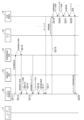
- FIG. 8 is a sequence diagram illustrating processing executed by the autonomous mobile body control system according to the first embodiment
- FIG. 9 is a sequence diagram following FIG. 8
- FIG. 10 is a sequence diagram following FIG. is.
- 8 to 10 show the processing executed by each device from when the user inputs position information to the user interface 11 until the current position information of the autonomous mobile body 12 is received. 8 to 10 are executed by the computers in the control units 10 to 15 executing the computer programs stored in the memory.
- step S201 the user uses the user interface 11 to access the WEB page provided by the system control device 10.
- step S202 the system control device 10 displays the position input screen as described with reference to FIG. 2 on the display screen of the WEB page.
- step S203 as described with reference to FIG. 2, the user selects an autonomous mobile object (mobility) and inputs position information (hereinafter referred to as position information) indicating a departure point, a transit point, and an arrival point.
- position information position information indicating a departure point, a transit point, and an arrival point.
- the location information may be a word (hereinafter referred to as a location word) that specifies a specific location such as a building name, station name, or address, or a specific location on a map displayed on a web page as a point (hereinafter referred to as a point). It may be a method to
- step S204 the system control device 10 saves the type information of the selected autonomous mobile body 12 and the input information such as the input position information.
- the system controller 10 stores the position word.
- the system control device 10 searches for the latitude and longitude corresponding to the point based on the simple map information stored in the position/route information management unit 10-3, Store latitude and longitude.
- step S205 the system control device 10 designates the type of route that can be moved (hereinafter referred to as route type) from the mobility type (moving body type) of the autonomous mobile body 12 designated by the user. Then, in step S206, it is transmitted to the route determination device 13 together with the positional information.
- route type the type of route that can be moved
- the type of mobility is, for example, a legally distinguished type of mobile object, such as a car, bicycle, or drone.
- the route types are, for example, general roads, expressways, motorways, predetermined sidewalks, roadside strips of general roads, and bicycle lanes.
- the route type is specified as a general road, a highway, a motorway, or the like.
- the mode of mobility is a bicycle, a predetermined sidewalk, a side strip of a general road, a bicycle lane, etc. are specified.
- step S207 the route determination device 13 inputs the received positional information into the owned map information as a departure point, a transit point, and an arrival point. If the positional information is a positional word, a search (preliminary search) is performed using the map information using the positional word, and the relevant latitude/longitude information is input. If the position information is latitude/longitude information, it is used by inputting it into the map information as it is. Furthermore, the route determination device 13 may search for routes in advance.
- step S208 the route determination device 13 searches for a route from the departure point to the arrival point via the intermediate points.
- the route to be searched is searched according to the route type. If a route has been searched in advance in step S208, the route searched in advance is appropriately changed based on the route type.
- step S209 the route determination device 13 outputs, as a result of the search, a route from the departure point to the arrival point via the waypoints (hereinafter referred to as route information) in GPX format (GPS eXchange Format), and system control is performed.
- route information a route from the departure point to the arrival point via the waypoints
- GPX format GPS eXchange Format
- GPX format files are mainly divided into three types: waypoints (point information without order), routes (point information with order with time information added), and tracks (collection of multiple point information: trajectory). is configured to
- latitude/longitude are described as attribute values of each point information, altitude, geoid height, GPS reception status/accuracy, etc. are described as child elements.
- the minimum element required for a GPX file is latitude/longitude information for a single point, and any other information is optional.
- a route is output as route information, and is a set of point information consisting of latitude/longitude having an order relationship. Note that the route information may be in another format as long as it satisfies the above requirements.
- FIG. 11(A) is a diagram showing latitude/longitude information of the earth
- FIG. 11(B) is a perspective view showing the predetermined space 100 in FIG. 11(A).
- the center of the predetermined space 100 is defined as the center 101.
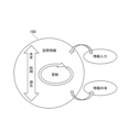
- FIG. 12 is a diagram schematically showing spatial information in the space 100. As shown in FIG.
- the format divides the three-dimensional space of the earth into spaces for each predetermined unit volume determined by the range starting from latitude/longitude/height.
- a unique identifier is added to the space to make it manageable.
- the space 100 is displayed as a predetermined three-dimensional space.
- a space 100 is defined by a center 101 of 20 degrees north latitude, 140 degrees east longitude, and height (altitude, altitude) H, and the width in the latitudinal direction is defined as D, the width in the longitudinal direction as W, and the width in the height direction as T. is a partitioned space. In addition, it is one space obtained by dividing the space of the earth into spaces determined by ranges starting from latitude/longitude/height. Incidentally, such divided space 100 is called a voxel (VOXEL).
- each of the arranged divided spaces has its horizontal position defined by latitude/longitude, overlaps in the height direction, and the position in the height direction is defined by height.
- the center 101 of the divided space is set as the starting point of latitude/longitude/height in FIG. 11B, the starting point is not limited to this. It is good as Also, the shape may be a substantially rectangular parallelepiped, and when considering the case of laying on a spherical surface such as the earth, it is better to set the top surface of the rectangular parallelepiped slightly wider than the bottom surface, so that it can be arranged without gaps.
- information on the types of objects that exist or can enter the range of the space 100 and time limits are associated with unique identifiers.
- the formatted spatial information is stored in chronological order from the past to the future. Note that, in the present embodiment, associating and linking are used in the same meaning.
- the conversion information holding device 14 associates with the unique identifier the spatial information regarding the types of objects that can exist or can enter a three-dimensional space defined by latitude/longitude/height and the time limit, and formats the format database 14-. Saved in 4.
- the spatial information is updated at predetermined update intervals based on information supplied by information supply means such as an external system (for example, the sensor node 15) communicatively connected to the conversion information holding device 14. Then, the information is shared with other external systems communicably connected to the conversion information holding device 14 . For applications that do not require time-related information, it is possible to use spatial information that does not contain time-related information. Also, non-unique identifiers may be used instead of unique identifiers.
- information about the type of an object that can exist or enter a three-dimensional space defined by latitude/longitude/height and the time limit (hereinafter referred to as spatial information) is associated with a unique identifier. formatted and stored in the database. Space-time can be managed by formatted spatial information.
- the conversion information holding device 14 of the first embodiment executes a formatting step of formatting and saving information about update intervals of spatial information in association with unique identifiers.
- the update interval information formatted in association with the unique identifier may be the update frequency, and the update interval information includes the update frequency.
- step S210 the system control device 10 confirms the interval between each piece of point information in the received route information. Then, the position point group data is created by matching the interval of the point information with the interval between the starting point positions of the divided spaces defined by the format.
- the system control device 10 thins out the point information in the route information according to the interval of the starting point positions of the divided spaces, and uses it as position point cloud data. do. Also, if the interval of point information is larger than the interval between the starting point positions of the divided spaces, the system control device 10 interpolates the point information within a range that does not deviate from the route information to obtain position point group data.
- step S211 in Fig. 9 the system control device 10 transmits the latitude/longitude information of each point information of the position point cloud data to the conversion information holding device 14 in the order of the route.
- step S212 the conversion information holding device 14 searches the format database 14-4 for a unique identifier corresponding to the received latitude/longitude information, and transmits it to the system control device 10 in step S213.
- step S214 the system control device 10 arranges the received unique identifiers in the same order as the original position point cloud data, and stores them as route information using the unique identifiers (hereinafter referred to as format route information).
- the system control device 10 as the route generation means acquires the spatial information from the database of the conversion information holding device 14, and based on the acquired spatial information and the type information of the mobile object, Generating route information about travel routes.
- FIG. 13(A) is an image diagram of route information displayed as map information
- FIG. 13(B) is an image diagram of route information using position point cloud data displayed as map information
- FIG. 13(C) is an image diagram using unique identifiers.
- FIG. 10 is an image diagram showing route information as map information;
- 120 is route information
- 121 is a non-movable area through which the autonomous mobile body 12 cannot pass
- 122 is a movable area where the autonomous mobile body 12 can move.
- the route information 120 generated by the route determining device 13 based on the positional information of the departure point, waypoints, and arrival points designated by the user passes through the departure point, waypoints, and arrival points, and is displayed on the map information. It is generated as a route passing over the movable area 122 .
- 123 is a plurality of pieces of position information on route information. After acquiring the route information 120 , the system control device 10 generates position information 123 arranged at predetermined intervals on the route information 120 .
- the position information 123 can be represented by latitude/longitude/height, respectively, and this position information 123 is called position point cloud data in the first embodiment. Then, the system control device 10 transmits the position information 123 (latitude/longitude/height of each point) one by one to the conversion information holding device 14 and converts them into unique identifiers.
- 124 is positional space information in which the positional information 123 is converted into a unique identifier one by one, and the spatial range defined by the unique identifier is represented by a rectangular frame.
- the location space information 124 is obtained by converting the location information into a unique identifier.
- the route represented by the route information 120 is converted into continuous position space information 124 and represented.
- Each piece of position space information 124 is associated with information about the types of objects that can exist or enter the space and the time limit. This continuous position space information 124 is called format route information in the first embodiment.
- step S215 the system control device 10 downloads the spatial information associated with each unique identifier of the format path information from the conversion information holding device 14.
- step S216 the system control device 10 converts the space information into a format that can be reflected in the three-dimensional map of the cyberspace of the autonomous mobile body 12, and information indicating the positions of multiple objects (obstacles) in the predetermined space.
- the cost map may be created with respect to the space of all routes in the format route information at first, or may be created in a form divided by fixed areas and updated sequentially.
- step S217 the system control device 10 associates the format route information and the cost map with the unique identification number (unique identifier) assigned to the autonomous mobile body 12 and stores them.
- the autonomous mobile body 12 monitors (hereinafter, polling) its own unique identification number via the network at predetermined time intervals, and downloads the associated cost map in step S218.
- the autonomous mobile body 12 reflects the latitude/longitude information of each unique identifier of the format route information as route information on the three-dimensional map of cyberspace created by itself.
- step S220 the autonomous mobile body 12 reflects the cost map on the three-dimensional map of cyberspace as obstacle information on the route. If the cost map is created in a form that is divided at regular intervals, after moving the area in which the cost map was created, download the cost map of the next area and update the cost map.
- step S221 the autonomous mobile body 12 moves along the route information while avoiding the objects (obstacles) entered in the cost map. That is, movement control is performed based on the cost map.
- step S222 the autonomous mobile body 12 moves while performing object detection, and moves while updating the cost map using the object detection information if there is a difference from the cost map. Also, in step S223, the autonomous mobile body 12 transmits difference information from the cost map to the system control device 10 together with the corresponding unique identifier.
- the system control device 10 that has acquired the difference information between the unique identifier and the cost map transmits the spatial information to the conversion information holding device 14 in step S224 of FIG. Update the spatial information of the unique identifier.
- the content of the spatial information updated here does not directly reflect the difference information from the cost map, but is abstracted by the system control device 10 and then sent to the conversion information holding device 14 . Details of the abstraction will be described later.
- step S226 the autonomous mobile body 12 moving based on the format route information informs the system controller 10 of the space it is currently passing through each time it passes through the divided space associated with each unique identifier. Send the associated unique identifier.
- the system control device 10 grasps the current position of the autonomous mobile body 12 on the format route information.
- the system control device 10 can grasp where the autonomous mobile body 12 is currently located in the format route information. Incidentally, the system control device 10 may stop holding the unique identifier of the space through which the autonomous mobile body 12 has passed, thereby reducing the holding data capacity of the format route information.
- step S227 the system control device 10 creates the confirmation screen 50 and the map display screen 60 described with reference to FIGS. do.
- the system control device 10 updates the confirmation screen 50 and the map display screen 60 each time a unique identifier indicating the current position is transmitted from the autonomous mobile body 12 to the system control device 10 .
- the sensor node 15 saves the detection information of the detection range, abstracts the detection information in step S229, and transmits it as spatial information to the conversion information holding device 14 in step S230. Abstraction is information such as whether or not an object exists, or whether or not the state of existence of the object has changed, and is not detailed information about the object.
- step S231 the conversion information holding device 14 stores the spatial information, which is the abstracted detection information, in association with the unique identifier of the position corresponding to the spatial information. This results in spatial information being stored in one unique identifier in the format database.
- the external system uses the spatial information in the conversion information holding device 14 to obtain the detected information in the sensor node 15 via the conversion information holding device 14. is obtained and utilized.
- the conversion information holding device 14 also has a function of connecting the communication standards of the external system and the sensor node 15 .
- the conversion information holding device 14 has a function of connecting data of multiple devices with a relatively small amount of data.
- steps S215 and S216 of FIG. 9 when the system control device 10 needs detailed object information when creating a cost map, detailed information is sent from an external system storing detailed detection information of spatial information. should be downloaded and used.
- the sensor node 15 updates the spatial information on the route of the format route information of the autonomous mobile body 12 .
- the sensor node 15 acquires detection information in step S232 of FIG. 10, generates abstracted spatial information in step S233, and transmits it to the conversion information holding device 14 in step S234.
- the conversion information holding device 14 stores the spatial information in the format database 14-4 in step S235.
- the system control device 10 checks changes in the spatial information in the managed format path information at predetermined time intervals, and downloads the spatial information in step S236 if there is a change. Then, in step S237, the cost map associated with the unique identification number assigned to the autonomous mobile body 12 is updated. In step S238, the autonomous mobile body 12 recognizes the update of the cost map by polling, and reflects it on the three-dimensional map of the cyberspace created by itself.
- the autonomous mobile body 12 can recognize in advance changes in the route that the autonomous mobile body 12 cannot recognize, and can respond to such changes.
- a unique identifier is transmitted in step S240.
- the system control device 10 Upon recognizing the unique identifier, the system control device 10 displays an arrival indication on the user interface 11 in step S241, and terminates the application. According to Embodiment 1, as described above, it is possible to provide a digital architecture format and an autonomous mobile body control system using the same.
- the format database 14-4 stores information (spatial information) about the types of objects that can exist or enter the space 100 and the time limit from the past. It is stored in chronological order such as the future. Further, the spatial information is updated based on information input from an external sensor or the like communicably connected to the conversion information holding device 14, and can be connected to the conversion information holding device 14 via a network by wired communication or wireless communication. Information is shared with other external systems.
- the type information of objects in the space is information that can be obtained from map information, such as roadways, sidewalks, and bicycle lanes on roads.
- map information such as roadways, sidewalks, and bicycle lanes on roads.
- information such as the traveling direction of mobility on a roadway, traffic regulations, etc. can also be defined as type information.
- type information it is also possible to define type information in the space itself.
- the conversion information holding device 14 can be connected to a system control device that manages information on roads and a system control device that manages information on sections other than roads.
- the system control device 10 can transmit position point cloud data collectively representing the position information 123 of FIG. Similarly, a system control device that manages information on roads and a system control device that manages information on sections other than roads can also transmit corresponding data to the conversion information holding device 14 .
- the corresponding data is the position point cloud data information managed by the system control device that manages road information and the system control device that manages information on sections other than roads.
- Each point of the position point cloud data is hereinafter referred to as a position point.
- the space information update interval differs according to the type of object existing in the space. That is, when the type of object existing in the space is a moving object, the length of time is set to be shorter than when the type of object existing in the space is not a moving object. Also, when the type of the object existing in the space is a road, the type of the object existing in the space is made shorter than in the case of the partition.
- the update interval of the space information about each object should be different according to the type of each object (eg moving body, road, section, etc.). Spatial information about the state and time of each of a plurality of objects existing in the space is associated with the unique identifier, formatted and stored. Therefore, the load for updating spatial information can be reduced.
- spatial information is associated with a cubic voxel (VOXEL) of each divided space region obtained by dividing the space region of the real world.
- Spatial information may be associated with and stored in three-dimensional spatial regions having various shapes such as rectangular parallelepiped shapes, polygonal polygon shapes, and spherical shapes in addition to cubic shapes.
- the autonomous mobile bodies for which spatial information is used include various types/ A size is assumed.
- the spatial information linked to the voxels of each divided space area in the format database 14-4 it is possible to determine an appropriate movement route of the autonomous mobile body.
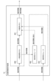
- FIG. 14 is a block diagram showing an internal configuration example of the conversion information holding device 14.
- the conversion information holding device 14 includes a temporary memory 200, a working memory 201, and storages 202 and 203 for saving.
- the temporary storage memory 200 and the work memory 201 are memories suitable for high-speed processing that can be written and read at high speed compared to the storage storages 202 and 203 .
- the storage storages 202 and 203 are slow in writing and reading (input/output) compared to the temporary storage memory 200 and the working memory 201, and are not suitable for high-speed processing, but they are large-capacity storages. be.
- the temporary storage memory 200 functions as first storage means for performing a first storage step of storing static information in spatial information.
- the storage for storage 203 functions as a second storage means for performing a second storage step of storing dynamic information in the spatial information.
- the temporary storage memory 200, which is the first storage means has an input/output speed lower than that of the storage storage 203, which is the second storage means.
- the temporary storage memory 200 and the working memory 201 are composed of memories with relatively high manufacturing costs per storage capacity
- the storage storages 202 and 203 are composed of memories with relatively low manufacturing costs per storage capacity. be done.
- the temporary storage memory 200 and the working memory 201 are composed of, for example, RAM (Random Access Memory) such as DRAM (Dynamic RAM) and SRAM (Static RAM), which are volatile memories. Volatile memory loses its data when the power is turned off.
- RAM Random Access Memory
- DRAM Dynamic RAM
- SRAM Static RAM
- the storage storages 202 and 203 are configured by ROM (Read Only Memory) such as EPROM (Erasable Programmable ROM) and EEPROM (Electrically EPROM), which are non-volatile memories, for example.
- ROM Read Only Memory
- EPROM Erasable Programmable ROM
- EEPROM Electrical EPROM
- Non-volatile memory retains its data even when the power is turned off.
- the storages 202 and 203 for preservation may be composed of flash memory, SSD (Solid State Drive), HDD (Hard Disk Drive), or the like.
- the temporary storage memory 200, working memory 201, and storage storages 202 and 203 are arranged, for example, in the format database 14-4 shown in FIG.
- the temporary storage memory 200 and the work memory 201 may be composed of one integrated memory, or may be composed of two or more divided storage areas within the same memory.
- the storages 202 and 203 may be configured as one integrated storage, and configured as two or more divided storage areas within the same storage.
- Either or both of the temporary storage memory 200 and the working memory 201 may be arranged in the information storage section 14-5. Either or both of the temporary storage memory 200 and the working memory 201 may be arranged in the control unit 14-3.
- Spatial information consists of dynamic information such as information on the presence of vehicles and pedestrians, information on the status of traffic lights (red/blue (green)/yellow), and static information such as information on road surfaces and the presence of structures.
- dynamic information and semi-dynamic information (semi-dynamic information) defined by a dynamic map are handled as dynamic information in this embodiment
- static information and semi-static information (semi-static information) defined by a dynamic map are treated as dynamic information in this embodiment.
- static information is treated as static information in this embodiment.
- the dynamic information in the dynamic map includes, for example, information transmitted/exchanged between moving objects, traffic signal display information, pedestrian/bicycle information at intersections, information on vehicles going straight through intersections, etc., and the update frequency in units of one second can be obtained.
- semi-dynamic information can be obtained within one minute at the time of observation, such as actual traffic congestion, temporary driving restrictions, temporary driving obstacles such as falling objects and disabled people, actual accident conditions, and narrow-area weather information. It refers to information for which the update frequency of is required.
- quasi-static information refers to information that requires an update frequency within one hour, such as traffic control information due to road construction or events, wide-area weather information, and traffic congestion forecasts.
- Static information is information that is required to be updated within one month, such as roads, structures on roads, lane information, road surface information, and permanent regulation information. So to speak, it refers to the map information that is the base of the dynamic map.
- dynamic information, semi-dynamic information, and semi-static information defined in the dynamic map are treated as dynamic information in this embodiment, and static information defined in the dynamic map is treated as static information in this embodiment. may be treated as information.
- the dynamic information defined by the dynamic map is handled as the dynamic information in this embodiment, and the semi-dynamic information, semi-static information, and static information defined in the dynamic map are treated as the static information in this embodiment. may be treated as information.
- the update frequency has a relationship of dynamic information>semi-dynamic information>semi-static information>static information
- the dynamic information is stored in the temporary storage memory 200 suitable for high-speed processing.
- the static information since the static information has the lowest update frequency, it is not stored in the temporary storage memory 200 but stored in the storage storage 203 . As a result, use of the storage area of the temporary storage memory 200 is suppressed.
- the dynamic information is stored in the temporary memory 200, it is also stored in the storage storage 202 so that the past situation can be investigated in the event of an accident or the like.
- the received dynamic information may be stored in the temporary storage memory 200 and concurrently stored directly in the storage storage 202 without going through the temporary storage memory 200 .
- the working memory 201 temporarily stores dynamic information read from the temporary memory 200 or the storage storage 202 and static information read from the storage storage 203 . Then, the dynamic information and static information that have undergone integration processing in the working memory 201 are transmitted to the system control device 10 or the like via the network connection unit 14-6 as communication means.
- the working memory 201 functions as a third storage means that reads, integrates and stores the respective spatial information stored in the first storage means and the second storage means. It also functions as integrated spatial information generating means for performing an integrated spatial information generating step for generating integrated spatial information.
- the control unit 14-3 controls the writing and reading of dynamic information and static information to/from the memory/storage.
- the dynamic information stored in the temporary storage memory 200 is deleted sequentially from the oldest information when the usage capacity of the temporary storage memory 200 exceeds a predetermined limit value.
- the system control device 10 downloads the spatial information from the conversion information holding device 14, converts it into a format that can be reflected in the three-dimensional map of the cyber space of the autonomous mobile body 12, and converts it into a predetermined Create a cost map in space. Then, the autonomous mobile body 12 downloads the cost map at predetermined time intervals and performs movement control based on the cost map.
- the spatial information is downloaded from the conversion information holding device 14.
- the spatial information includes static information and dynamic information, which are stored in different storage areas of the conversion information holding device 14. stored.
- the cost map necessary for controlling the movement of the autonomous mobile body 12 is created by combining these static information and dynamic information. A specific method of creating this cost map will be described with reference to FIGS. 15 to 20.
- FIG. Here, the object of movement control is assumed to be the autonomous mobile body 12 shown in FIG.
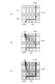
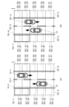
- FIGS. 15A and 15B are diagrams showing examples of the state of the roadway and its surrounding space, showing the state of looking down from above on the roadway 701-5 with one lane in each direction, its surroundings, and its space. ing.
- the upper side of the paper faces the north direction.
- Spaces 701-21 to 701-25 and 701-31 to 701-35 are spaces on the roadway 701-5, and the mobile body moves through these spaces.
- a building 701-7 exists in the spaces 701-14 and 701-15.
- FIG. 15(A) the mobile object 701-4 exists in the spaces 701-34 and 701-35, and the mobile object 701-4 is moving southward in the figure. After a certain period of time, the moving body 701-4 moves to the spaces 701-33 and 701-34 as shown in FIG. 15(B).
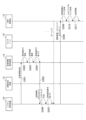
- FIG. 16 is a sequence diagram illustrating processing executed by the autonomous mobile control system according to the embodiment. Each step of the sequence shown in FIG. 16 is performed by the CPU as a computer in the control units 10, 12 to 15 executing the computer program stored in the memory.
- the cost map creation range in this embodiment is a predetermined range 701-8 in the course direction of the autonomous mobile body 12 in FIG.
- step S301 the system control device 10 transmits the position information of the predetermined range 701-8 in the course direction of the autonomous mobile body 12 to the conversion information holding device .
- the location information includes latitude/longitude information and the like of each point information of the location point cloud data.
- step S302 the conversion information holding device 14 searches the format database 14-4 for a unique identifier corresponding to the received latitude/longitude information. Then, in step S303, the conversion information holding device 14 reads out the spatial information associated with each unique identifier from the temporary storage memory 200 and the storage storage 203, copies it, and stores it in the working memory 201.
- FIG. 1 the conversion information holding device 14 searches the format database 14-4 for a unique identifier corresponding to the received latitude/longitude information.
- the spaces indicated by the unique identifier in the predetermined range 701-8 in the course direction of the autonomous mobile body 12 are spaces 701-14, 701-15, 701-24, 701-25, 701-34, 701-35. , 701-44 and 701-45. Get information about these spaces.
- objects such as a moving object 701-4, a roadway 701-5, a sidewalk 701-6, and a building 701-7 exist in these spaces.
- static objects such as the roadway 701-5, the sidewalk 701-6, and the building 701-7 are stored in the storage storage 203 as space static information for each unique identifier corresponding to the latitude/longitude information of each space.
- a moving object such as the moving object 701-4 is stored in the temporary storage memory 200 as spatial dynamic information for each unique identifier corresponding to the latitude/longitude information of each space.
- step S303 the conversion information holding device 14 integrates each piece of spatial information copied to the working memory 201 in step S304, associates it with each corresponding unique identifier, and transmits it to the system control device 10 in step S305. .
- step S306 the system control device 10 converts the acquired integrated space information into a format that can be reflected in the three-dimensional map of the cyber space of the autonomous mobile body 12, and the predetermined range 701-8 Create a cost map.
- the system control device 10 functions as control means for creating a cost map regarding movement control of moving bodies based on the integrated spatial information.
- FIG. 17 is a diagram showing a predetermined range 701-8 in the forward field of view of the autonomous mobile body 12 in the state of FIG. 15(A).
- spaces 701-14 and 701-15 where buildings 701-7 exist spaces 701-34 and 701-35 where moving objects 701-4 exist, and spaces 701-44 and 701 where sidewalks 701-6 exist.
- -45 is a space in which an obstacle may exist when the autonomous mobile body 12 moves. In other words, these spaces are recognized as costs, and can be represented as hatched lines in FIG. 17 when illustrated as a cost map.
- step S307 of FIG. 16 the system control device 10 associates (associates) the format route information and the cost map with the unique identification number assigned to the autonomous mobile body 12 and stores them.
- the autonomous mobile body 12 monitors (hereinafter, polls) its own unique identification number via the network at predetermined time intervals, and downloads the associated cost map in step S308.
- step S309 the autonomous mobile body 12 reflects the latitude/longitude information of each unique identifier of the format route information as route information on the three-dimensional map of cyberspace created by itself.
- step S310 the autonomous mobile body 12 reflects the cost map on the three-dimensional map of cyberspace as obstacle information on the route.
- the autonomous mobile body 12 moves along the route information while avoiding objects (obstacles) input in the cost map. That is, movement control is performed based on the cost map. Specifically, in FIG. 17, the autonomous mobile body 12 can move through spaces 701-24 and 701-25.
- static information and dynamic information data are acquired from the conversion information holding device 14, and the system control device generates a cost map.
- the spatial information of the dynamic information changes its state sequentially every second, for example.
- the state of spatial information of static information such as buildings hardly changes. Therefore, in updating the once generated cost map, it is desirable to update only the spatial information of the dynamic information from the viewpoint of the processing load of the conversion information holding device 14 in step S303 and the network load in information transmission in step S308. .
- FIG. 18 is a sequence diagram for explaining the method of creating a cost map and updating the cost map. Based on FIG. explain. The steps of the sequence shown in FIG. 18 are performed by the CPU as a computer in the control units 10, 12 to 15 executing the computer program stored in the memory.
- step S321 the system control device 10 transmits the position information of the predetermined range 701-8 in the course direction of the autonomous mobile body 12 to the conversion information holding device .
- the location information includes latitude/longitude information and the like of each point information of the location point cloud data.
- acquisition classification information indicating whether to acquire static information and dynamic information of each space corresponding to the predetermined range 701-8 or to acquire only dynamic information is sent together.
- the system control device 10 has created a cost map in the predetermined range 701-8, only dynamic information is acquired, and if no cost map has been created, static information and dynamic information are acquired. Send the acquisition classification information so as to acquire .
- the acquired classification information is G1 when static information and dynamic information of each space are acquired, and G0 when only dynamic information is acquired.
- step S322 the conversion information holding device 14 searches each unique identifier corresponding to the received latitude/longitude information from the format database 14-4. After that, if the acquired classification information is G1, the conversion information holding device 14 copies the spatial data from the temporary storage memory 200 and the storage storage 203 to the working memory 201 in step S323.
- steps S323 and S324 may be performed in parallel as shown in FIG. 18, or may be performed sequentially.
- the conversion information holding device 14 links each piece of spatial information copied to the working memory 201 in step S325 with each corresponding unique identifier, and transmits it to the system control device 10 in step S326.
- step S327 the system control device 10 converts the acquired space information into a format that can be reflected in the three-dimensional map of the cyber space of the autonomous mobile body 12, and the predetermined Create a cost map for range 701-8.
- step S328 only the acquired space information is updated for the cost map of the predetermined range 701-8.
- steps S327 and S328 may be performed in parallel as shown in FIG. 18, or may be performed sequentially.
- the spatial information of the spaces 701-34 and 701-35 in which the moving body 701-4 is present which is dynamic information, is obtained, and the cost map of the predetermined range 701-8 is calculated for the spaces 701-34 and 701- 35 information is updated.
- the moving object 701-4 remains in the space 701-34 while the moving object 701-4 no longer exists in the space 701-35.
- step S329 the system control device 10 associates the format route information and the cost map with the unique identification number assigned to the autonomous mobile body 12 and stores them.
- the autonomous mobile body 12 monitors (hereinafter, polls) its own unique identification number via the network at predetermined time intervals, and downloads the associated cost map in step S330.
- step S331 the autonomous mobile body 12 reflects the latitude/longitude information of each unique identifier of the format route information as route information on the three-dimensional map of cyberspace created by itself.
- step S332 the autonomous mobile body 12 reflects the cost map on the three-dimensional map of cyberspace as obstacle information on the route.
- step S333 the autonomous mobile body 12 moves along the route information while avoiding objects (obstacles) input in the cost map. That is, autonomous movement control is performed based on the cost map.
- the data of static information and dynamic information, or only the data of dynamic information is acquired from the conversion information holding device 14, and based on these information, the system control device generates a cost map Generate and update the .
- the system control device 10 generates and updates the cost map required for movement control of the autonomous mobile body 12.
- the cost map is generated and updated using the conversion information. An example performed by the holding device 14 will be described.
- FIG. 19 is a block diagram showing an internal configuration example of the conversion information holding device 14 according to the second embodiment.
- a first cost map 205 and a second cost map 206 are generated in working memory 201 .
- a first cost map 205 and a second cost map 206 are generated based on information in the temporary storage memory 200 and storage storage 202, respectively.
- the working memory 201 as integrated spatial information generating means can hold a plurality of cost maps.
- the first cost map 205 is a cost map to be used for movement control of the autonomous mobile body 12a.
- the second cost map 206 is a cost map for use in movement control of, for example, the autonomous mobile body 12b traveling on a sidewalk.
- the autonomous mobile body 12a is, for example, an automatic driving car that moves on a roadway
- the autonomous mobile body 12b is, for example, a parcel delivery robot that moves on a sidewalk.
- a moving body moving on a sidewalk roadways, other moving bodies, and buildings are determined as costs, and sidewalks are not determined as costs. That is, the cost map is made different according to the type of the autonomous mobile body and the place of travel. In this way, a cost map is generated that indicates whether or not the autonomous mobile body can pass through depending on the type of the autonomous mobile body and the travel location.
- FIG. 20 is a flowchart for explaining processing executed by the conversion information holding device 14 according to the second embodiment. 20 is performed by the CPU of the control section 14-3 of the conversion information holding device 14 executing the computer program stored in the memory.
- step S353 the control unit 14-3 creates a cost map within a predetermined space based on these pieces of information. Furthermore, in step S354, the control unit 14-3 determines whether or not a predetermined time T1 has elapsed.
- the predetermined time T1 is the elapsed time (period) from the creation of the cost map and the update of the static information of the cost map, for example several days. This is because static information such as buildings does not change in a short period of time.
- step S354 the process proceeds to step S357.
- the control unit 14-3 waits until a predetermined time T2 elapses.
- the predetermined time T2 is the elapsed time from the creation of the cost map and the update of the dynamic information of the cost map, and is, for example, several seconds. This is because there is a possibility that dynamic information such as a moving object changes its position in a short period of time.
- step S356 the cost map within the predetermined space is updated. If it is determined in step S359 that the cost map does not need to be updated in the future, this process ends. If not, the process returns to step S354 and continues.
- the static information and the dynamic information are acquired when the predetermined time T1 or the predetermined time T2 has passed, but it is not limited to this.
- Embodiment 2 the creation and updating of the first cost map for the autonomous mobile body 12a of FIG. 19 has been described using the flowchart of FIG. 20, but the creation and updating of the second cost map of FIG. can be implemented.
- a cost map for drone operations may be created.
- a plurality of cost maps are created in the conversion information holding device 14, but a plurality of cost maps may be created in the system control device 10, for example.
- Embodiments 1 and 2 in an autonomous mobile control system using spatial information in a three-dimensional space defined by latitude/longitude/height, static information is stored in a relatively low-speed storage storage. , and dynamic information is stored in relatively fast temporary memory. Therefore, network traffic and data processing load can be optimized.
- data input/output can be speeded up when high-speed access is required according to the position indicated by the unique identifier.
- the cost map is created from the static information and dynamic information stored in each storage location, the necessary data can be stored with low latency without high-speed access to all data. can be pulled out.
- cost maps are created according to the type of mobile object, a more appropriate cost map can be created.
- the cost map is created based on static information and dynamic information, and the cost map is updated based on the dynamic information, efficiency can be improved.
- the cost map may be created by using relatively distant information from a relatively low speed storage storage and relatively near information from a relatively high speed temporary storage memory. . That is, the static information may include spatial information relatively farther than the dynamic information.
- the area where the state changes frequently creates a cost map with information from a relatively high-speed temporary storage memory, and the road information and structure information between intersections are created.
- a cost map may be created with information from relatively slow storage storage.
- the size of the cost map creation range in this embodiment is not limited to a fixed value. , can be of any size. That is, there may be a plurality of sizes of cost maps relating to movement control of the moving body.
- the size of the cost map creation range may be changed depending on the mobile object.
- the first cost map for the autonomous mobile body 12a that moves on the roadway and the second cost map for the autonomous mobile body 12b that moves on the sidewalk are created.
- the moving speed of the moving object (cost object) moving on the roadway is relatively faster than the moving speed of the moving object (cost object) moving on the sidewalk.
- the size of the cost map may differ depending on the moving object whose movement is controlled.
- the size of the cost map creation range may be changed according to the position in space.
- the cost map creation range is enlarged, and for areas with a low possibility of changing conditions (such as other mobile narrow alleys, etc.), the cost map creation range may be reduced. That is, the size of the cost map may differ depending on the position in the three-dimensional space defined by latitude/longitude/height.
- the moving object will acquire cost information over a wider range to ensure that it moves while avoiding objects (obstacles such as people and other vehicles).
- objects obstacles such as people and other vehicles.
- the size of the cost map creation range may be changed according to the moving speed of the moving object that uses the cost map.
- the cost map creation range may be widened. That is, the size of the cost map may differ depending on the moving speed of the moving object.
- the mobile object of this embodiment is not limited to an autonomous mobile object such as an AGV (Automatic Guided Vehicle) or an AMR (Autonomous Mobile Robot).
- AGV Automatic Guided Vehicle
- AMR Automatic Mobile Robot
- it can be any mobile device that moves, such as automobiles, trains, ships, airplanes, robots, and drones.
- part of the control system of the present embodiment may or may not be mounted on those moving bodies.
- this embodiment can be applied to remote control of a moving object.
- the present invention may be realized by supplying a storage medium recording software program code (control program) for realizing the functions of the above-described embodiments to a system or apparatus. It is also achieved by the computer (or CPU or MPU) of the system or apparatus reading and executing the computer-readable program code stored in the storage medium.
- control program software program code
- the program code itself read from the storage medium implements the functions of the above-described embodiments, and the storage medium storing the program code constitutes the present invention.
Abstract
3次元空間における静的情報と動的情報を用いて統合空間情報を生成可能な制御システムであって、緯度/経度/高さによって定義される3次元の空間に存在する物体の情報を空間情報として固有識別子と関連付けてフォーマット化するフォーマット化手段と、前記空間情報の内の静的情報を保存する第1の記憶手段と、前記空間情報の内の動的情報を保存する第2の記憶手段と、前記第1の記憶手段と前記第2の記憶手段に保存された夫々の前記空間情報を読出して統合した統合空間情報を生成する統合空間情報生成手段と、を有する。
Description
本発明は、3次元空間における情報を用いる制御システム、制御方法、及び記憶媒体等に関するものである。
近年、自律走行モビリティや空間認識システムなどの技術革新に伴い、異なる組織や社会の構成員の間でデータやシステムをつなぐ全体像(以下、デジタルアーキテクチャ)の開発が促進されている。
特許文献1では、ユーザの提供する時空間管理データに従って単一のプロセッサが時空間領域を時間及び空間で分割して、複数の時空間分割領域を生成している。又、時空間分割領域の時間及び空間の近傍性を考慮して、複数の時空間分割領域の各々を一意に識別するための、一次元の整数値で表現される識別子を割り当てている。
そして、その識別子が近い時空間分割領域のデータが記憶装置上で近くに配置されるように、時系列データの配置を決定する時空間データ管理システムが開示されている。
しかしながら、上記特許文献1においては、生成された領域に関するデータを識別子で把握できるのはそれを生成したプロセッサ内でのみである。よって、異なるシステムのユーザがその空間分割領域の情報を活用することができない。
そこで、本発明は、3次元空間における静的情報と動的情報を用いて統合空間情報を生成可能な制御システムを提供する。
本発明の1側面の制御システムは、
緯度/経度/高さによって定義される3次元の空間に存在する物体の情報を空間情報として固有識別子と関連付けてフォーマット化するフォーマット化手段と、
前記空間情報の内の静的情報を保存する第1の記憶手段と、
前記空間情報の内の動的情報を保存する第2の記憶手段と、
前記第1の記憶手段と前記第2の記憶手段に保存された夫々の前記空間情報を読出して統合した統合空間情報を生成する統合空間情報生成手段と、を有することを特徴とする。
緯度/経度/高さによって定義される3次元の空間に存在する物体の情報を空間情報として固有識別子と関連付けてフォーマット化するフォーマット化手段と、
前記空間情報の内の静的情報を保存する第1の記憶手段と、
前記空間情報の内の動的情報を保存する第2の記憶手段と、
前記第1の記憶手段と前記第2の記憶手段に保存された夫々の前記空間情報を読出して統合した統合空間情報を生成する統合空間情報生成手段と、を有することを特徴とする。
本発明によれば、3次元空間における静的情報と動的情報を用いて統合空間情報を生成可能な制御システムを提供することが出来る。
以下、図面を参照して本発明の実施形態を説明する。ただし、本発明は以下の実施形態に限定されるものではない。尚、各図において、同一の部材または要素については同一の参照番号を付し、重複する説明は省略または簡略化する。
尚、実施形態においては自律移動体等の制御に適用した例について説明するが、移動体はユーザが移動体の移動に関して少なくとも一部を操作可能なものであっても良い。即ち、例えばユーザに対して移動経路等に関する各種表示等を行い、その表示を参照してユーザが移動体の運転操作の一部を行う構成であっても良い。
<実施形態1>
図1は本発明の実施形態1に係る自律移動体制御システムの全体構成例を示す図である。図1に示すように、本実施形態の自律移動体制御システム(制御システムと略すこともある。)は、システム制御装置10、ユーザインターフェース11、自律移動体12、経路決定装置13、変換情報保持装置14、センサノード15等を備える。尚、ここで、ユーザインターフェース11はユーザ端末装置を意味する。
図1は本発明の実施形態1に係る自律移動体制御システムの全体構成例を示す図である。図1に示すように、本実施形態の自律移動体制御システム(制御システムと略すこともある。)は、システム制御装置10、ユーザインターフェース11、自律移動体12、経路決定装置13、変換情報保持装置14、センサノード15等を備える。尚、ここで、ユーザインターフェース11はユーザ端末装置を意味する。
尚、本実施形態では、図1に示される各装置はインターネット16を介して、後述される夫々のネットワーク接続部によって接続されている。しかし、例えば、LAN(Local Area Network)等の他のネットワークシステムを用いてもかまわない。又、システム制御装置10、ユーザインターフェース11、経路決定装置13、変換情報保持装置14等の一部は同一装置として構成しても構わない。
システム制御装置10、ユーザインターフェース11、自律移動体12、経路決定装置13、変換情報保持装置14、センサノード15は夫々、コンピュータとしてのCPUや、記憶媒体としてのROM、RAM、HDD等からなる情報処理装置を含んでいる。各装置の機能及び内部構成の詳細については後に説明する。
次に、自律移動体制御システムによって提供されるサービスアプリケーションソフトウェア(以下、アプリと略す。)について説明する。尚、説明にあたっては、先ず、ユーザが位置情報を入力する際にユーザインターフェース11に表示される画面イメージを図2(A)、(B)を用いて説明する。
続いて、ユーザが自律移動体12の現在位置を閲覧する際のユーザインターフェース11に表示される画面イメージを図3(A)、図3(B)を用いて説明する。また、自律移動体制御システムにおいて、どのようにアプリに対してユーザの操作がなされるのかを例を用いて説明する。
尚、本説明において、便宜上、地図表示は二次元の平面で説明するが、本実施の形態において、ユーザは「高さ」も含めた3次元的な位置指定が可能であり、「高さ」情報を入力することもできる。即ち、本実施形態ではアプリは3次元地図を表示することができる。
図2(A)はユーザが位置情報を入力する際の入力画面の例を示す図、図2(B)は使用する自律移動体を選択するための選択画面の例を示す図である。ユーザがユーザインターフェース11の表示画面を操作して、インターネット16にアクセスし、自律移動体制御システムの例えば経路設定アプリを選択すると、システム制御装置10のWEBページが表示される。
WEBページに先ず表示されるのは、自律移動体12を移動させる際に、出発地、経由地、到着地を設定するための出発地、経由地、到着地の入力画面40である。入力画面40には使用する自律移動体(例えば、自動運転可能なモビリティ)の一覧を表示させるための一覧表示ボタン48がある。ユーザが一覧表示ボタン48を押下すると、図2(B)で示すようにモビリティの一覧表示画面47が表示される。
ユーザは先ず、一覧表示画面47において使用する自律移動体(例えば、自動運転可能なモビリティ)を選択する。一覧表示画面47においては例えばM1~M3のモビリティが選択可能に表示されているが、数はこれに限定されない。
ユーザがM1~M3のいずれかのモビリティをタッチ操作やクリック操作等によって選択すると、自動的に図2(A)の入力画面40に戻る。又、一覧表示ボタン48には、選択されたモビリティ名が表示される。その後ユーザは出発地として設定する場所を「出発地」の入力フィールド41に入力する。
又、ユーザは経由地として設定する場所を「経由地1」の入力フィールド42に入力する。尚、経由地は追加可能となっており、経由地の追加ボタン44を1回押下すると、「経由地2」の入力フィールド46が1つ追加表示され、追加する経由地を入力することができる。
経由地の追加ボタン44を押下する度に、「経由地3」、「経由地4」のように、入力フィールド46が押下に応じて追加表示され、追加する経由地を複数地点入力することができる。又、ユーザは到着地として設定する場所を「到着地」の入力フィールド43に入力する。尚、図には示していないが、入力フィールド41~43、46等をクリックすると、文字を入力するためのキーボード等が一時的に表示される。
そして、ユーザは決定ボタン45を押下することにより、自律移動体12の移動経路を設定することができる。図2の例では、出発地として”AAA”、経由地1として”BBB”、到着地として”CCC”と設定している。入力フィールドに入力する文言は、例えば住所等であってもよいし、緯度情報および経度情報(以下、緯度/経度情報とも記載する)や店名や電話番号などの、特定の位置を示すための位置情報を入力できるようにしてもよい。
図3(A)は自律移動体の現在位置を確認するための画面の例を示す図、図3(B)は自律移動体の現在位置を確認する際の地図表示画面の例を示す図である。
図3(A)の50は確認画面であり、図2(A)のような画面で自律移動体12の移動経路を設定した後に、不図示の操作ボタンの操作をユーザがすることによって表示される。
図3(A)の50は確認画面であり、図2(A)のような画面で自律移動体12の移動経路を設定した後に、不図示の操作ボタンの操作をユーザがすることによって表示される。
確認画面50では、自律移動体12の現在位置が例えば現在地56のように、ユーザインターフェース11のWEBページに表示される。従ってユーザは容易に現在位置を把握できる。
又、ユーザは更新ボタン57を押下することにより、画面表示情報を更新して最新状態を表示することができる。又、ユーザは経由地/到着地変更ボタン54を押下することにより、出発地、経由地、または到着地を変更することができる。即ち、ユーザは「出発地」の入力フィールド51、「経由地1」の入力フィールド52、「到着地」の入力フィールド53に夫々再設定したい場所を入力することで変更することができる。
図3(B)には、図3(A)の地図表示ボタン55を押下した場合に、確認画面50から切り替わる地図表示画面60の例が示されている。地図表示画面60では、現在地62の位置を地図上で表示することによって、自律移動体12の現在地をよりわかりやすく確認する。又、ユーザが戻るボタン61を押下した場合には、図3(A)の確認画面50に表示画面を戻すことができる。
以上のように、ユーザはユーザインターフェース11の操作により、自律移動体12を所定の場所から所定の場所まで移動するための移動経路を容易に設定できる。尚、このような経路設定アプリは、例えばタクシーの配車サービスや、ドローンの宅配サービスなどにも適用することができる。
次に図1における10~15の構成例と機能例に関して図4を用いて詳細に説明する。図4は、図1の10~15の内部構成例を示した機能ブロック図である。尚、図4に示される機能ブロックの一部は、各装置に含まれる不図示のコンピュータに、不図示の記憶媒体としてのメモリに記憶されたコンピュータプログラムを実行させることによって実現されている。
しかし、それらの一部又は全部をハードウェアで実現するようにしても構わない。ハードウェアとしては、専用回路(ASIC)やプロセッサ(リコンフィギュラブルプロセッサ、DSP)などを用いることができる。
又、図4に示される夫々の機能ブロックは、同じ筐体に内蔵されていなくても良く、互いに信号路を介して接続された別々の装置により構成しても良い。
図4において、ユーザインターフェース11は操作部11-1、制御部11-2、表示部11-3、情報記憶部(メモリ/HDD)11-4、ネットワーク接続部11-5を備える。ユーザインターフェース11は、例えば、スマートフォン、タブレット端末、またはスマートウォッチ等の情報処理装置である。
操作部11-1は、タッチパネルやキーボタンなどで構成されており、データの入力のために用いられる。表示部11-3は例えば液晶画面などであり、経路情報やその他のデータを表示するために用いられる。
図2、図3において示したユーザインターフェース11の表示画面は表示部11-3に表示される。ユーザは表示部11-3に表示されたメニューを用いて、移動経路の選択、情報の入力、情報の確認等を行うことができる。つまり操作部11-1及び表示部11-3はユーザが実際に操作をするための操作用のインターフェースを提供している。尚、操作部11-1と表示部11-3を別々に設ける代わりに、タッチパネルによって操作部と表示部を兼用しても良い。
制御部11-2は、コンピュータとしてのCPUを内蔵し、ユーザインターフェース11における各種アプリの管理や、情報入力、情報確認などのモード管理を行い、通信処理を制御する。又、システム制御装置内の各部における処理を制御する。
情報記憶部(メモリ/HDD)11-4は、例えばCPUが実行するためのコンピュータプログラム等の、必要な情報を保有しておくための記録媒体である。ネットワーク接続部11-5は、インターネットやLAN、無線LANなどを介して行われる通信を制御する。
このように、本実施形態のユーザインターフェース11は、システム制御装置10のブラウザ画面に出発地、経由地、および到着地を入力画面40を表示する。また、ユーザによる出発地点、経由地点、到着地点といった位置情報の入力受付が可能である。ユーザインターフェース11は、ブラウザ画面に確認画面50及び地図表示画面60を表示することで、自律移動体12の現在位置を表示することができる。
図4における、経路決定装置13は、地図情報管理部13-1、制御部13-2、位置/経路情報管理部13-3、情報記憶部(メモリ/HDD)13-4、ネットワーク接続部13-5を備える。地図情報管理部13-1は、広域の地図情報を保有しており、指定された所定の位置情報に基づいて地図上のルートを示す経路情報を探索するとともに、探索結果の経路情報を位置/経路情報管理部13-3に送信する。
本実施形態では、地図情報は地形や緯度/経度/高度といった情報を含む3次元空間の地図情報である。また地図情報は、車道、歩道、進行方向、および交通規制といった道路交通法に関わる規制情報なども含む。
又、例えば地図情報は、時間帯によって一方通行となる場合や、時間帯によって歩行者専用道路となるものなど、時間によって変化する交通規制情報も、それぞれの時間情報とともに含む。制御部13-2は、コンピュータとしてのCPUを内蔵し、経路決定装置13内の各部における処理を制御する。
位置/経路情報管理部13-3は、ネットワーク接続部13-5を介して取得した自律移動体の位置情報を管理するとともに、地図情報管理部13-1に位置情報送信し、地図情報管理部13-1から取得した探索結果としての経路情報を管理する。制御部13-2は、外部システムの要求に従って、位置/経路情報管理部13-3で管理されている経路情報を所定のデータ形式に変換するとともに、外部システムに送信する。
以上のように、本実施形態においては、経路決定装置13は、指定された位置情報に基づいて道路交通法等に則した経路を探索し、経路情報を所定のデータ形式で出力できるように構成されている。
図4における、変換情報保持装置14は、位置/経路情報管理部14-1、固有識別子管理部14-2、制御部14-3、フォーマットデータベース14-4、情報記憶部(メモリ/HDD)14-5、ネットワーク接続部14-6を備える。ここで、ネットワーク接続部14-6は、後述の統合空間情報を外部からの要求に応じて送信する通信手段として機能している。
又、変換情報保持装置14は、緯度/経度/高さによって定義される3次元の空間に固有識別子を付与し、その空間に存在する物体の状態と時間に関する空間情報を上記固有識別子と関連付けてフォーマット化するフォーマット化手段として機能している。又、変換情報保持装置14は、上記のようなフォーマット化を行うフォーマット化ステップを有する。
位置/経路情報管理部14-1は、ネットワーク接続部14-6を通して取得した所定の位置情報を管理するとともに、制御部14-3の要求に従って位置情報を制御部14-3に送信する。制御部14-3は、コンピュータとしてのCPUを内蔵し、変換情報保持装置14内の各部における処理を制御する。
制御部14-3は、位置/経路情報管理部14-1から取得した位置情報と、フォーマットデータベース14-4で管理されているフォーマットの情報に基づいて、位置情報をフォーマットで規定された固有識別子に変換する。そして、固有識別子管理部14-2に送信する。
フォーマットについては後に詳しく説明するが、所定の位置を起点とした空間に識別子(以下、固有識別子)を割り振り、固有識別子によって空間を管理するものである。本実施形態においては、所定の位置情報を基に、対応する固有識別子や空間内の情報を取得することができる。
固有識別子管理部14-2は、制御部14-3にて変換した固有識別子を管理するとともにネットワーク接続部14-6を通じて送信する。フォーマットデータベース14-4は、フォーマットの情報を管理するとともに、制御部14-3の要求に従って、フォーマットの情報を制御部14-3に送信する。
又、ネットワーク接続部14-6を通じて取得した空間内の情報をフォーマットを用いて管理する。変換情報保持装置14は、外部の機器、装置、ネットワークにより取得された空間に関する情報を、固有識別子と紐づけて管理する。又、外部の機器、装置、ネットワークに対して固有識別子及びそれに紐づく空間に関する情報を提供する。
以上のように、変換情報保持装置14は、所定の位置情報を基に、固有識別子と空間内の情報を取得し、その情報を自身に接続された外部の機器、装置、ネットワークが共有できる状態に管理、提供する。又、変換情報保持装置14は、システム制御装置10に指定された位置情報を、固有識別子に変換し、システム制御装置10に提供する。
図4において、システム制御装置10は固有識別子管理部10-1、制御部10-2、位置/経路情報管理部10-3、情報記憶部(メモリ/HDD)10-4、ネットワーク接続部10-5を備える。位置/経路情報管理部10-3は、地形情報と緯度/経度情報の対応付けをした簡易的な地図情報を保持するとともに、ネットワーク接続部10-5を通して取得した所定の位置情報及び経路情報を管理する。
また位置/経路情報管理部10-3は、経路情報を所定の間隔で区切るとともに、区切った場所の緯度/経度といった位置情報を生成することもできる。固有識別子管理部10-1は、位置情報及び経路情報を固有識別子に変換した情報を管理する。
制御部10-2は、コンピュータとしてのCPUを有し、システム制御装置10の位置情報、経路情報、固有識別子の通信機能の制御を司り、システム制御装置10の各構成要素における処理を制御する。
又、制御部10-2は、ユーザインターフェース11にWEBページを提供するとともに、WEBページから取得した所定の位置情報を、経路決定装置13に送信する。又、経路決定装置13から所定の経路情報を取得し、経路情報の各位置情報を変換情報保持装置14に送信する。そして、変換情報保持装置14から取得した固有識別子に変換された経路情報を自律移動体12に送信する。
以上のように、システム制御装置10はユーザの指定する所定の位置情報の取得、位置情報及び経路情報の送受信、位置情報の生成、固有識別子を用いた経路情報の送受信を行えるように構成されている。
又、システム制御装置10は、ユーザインターフェース11に入力された位置情報に基づいて、自律移動体12が自律移動を行うのに必要な経路情報を収集するとともに、自律移動体12に固有識別子を用いた経路情報を提供する。尚、本実施形態では、システム制御装置10と経路決定装置13、変換情報保持装置14は例えばサーバーとして機能している。
図4において、自律移動体12は検出部12-1、制御部12-2、方向制御部12-3、情報記憶部(メモリ/HDD)12-4、ネットワーク接続部12-5、駆動部12-6を備える。検出部12-1は、例えば複数の撮像素子を有し、複数の撮像素子から得られた複数の撮像信号の位相差に基づき測距を行う機能を有する。
又、周辺の地形・建物の壁などの障害物といった検出情報(以下、検出情報)を取得し、検出情報と地図情報に基づき自己位置を推定する自己位置推定機能を有する。
又、検出部12-1は、GPS(Global Positioning System)などの自己位置検出機能と、例えば地磁気センサなどの方向検出機能を有する。更に、取得した検出情報と自己位置推定情報と方向検出情報を基に、制御部12-2はサイバー空間の3次元マップを生成することができる。
ここで、サイバー空間の3次元マップとは、現実世界の地物位置と等価な空間情報を、デジタルデータとして表現可能なものである。このサイバー空間の3次元マップ内には、現実世界に存在する自律移動体12や、その周辺の地物情報が、デジタルデータとして空間的に等価な情報として保持されている。従って、このデジタルデータを用いることで、効率的な移動が可能である。
以下図5を例として、本実施形態で用いるサイバー空間の3次元マップについて説明する。図5(A)は、現実世界における自律移動体12とその周辺の地物情報として存在する柱99の空間的位置関係を示した図、図5(B)は自律移動体12と柱99を、位置P0を原点とする任意のXYZ座標系空間にマッピングした状態を示した図である。
図5(A)、(B)において、自律移動体12の位置は、自律移動体12に搭載された不図示のGPS等によって取得された緯度経度の位置情報から、自律移動体12内の位置α0として特定される。又、自律移動体12の方位は不図示の電子コンパス等によって取得された方位αYと自律移動体12に移動方向12Yの差分によって特定される。
又、柱99の位置は、予め測定された位置情報から頂点99-1の位置として特定される。また自律移動体12の測距機能によって、自律移動体12のα0から頂点99-1までの距離を取得することが可能である。図5(A)においては移動方向12YをXYZ座標系の軸としてα0を原点とした場合に、頂点99-1の座標(Wx,Wy,Wz)として示される。
サイバー空間の3次元マップでは、この様に取得された情報がデジタルデータとして管理され、図5(B)のような空間情報としてシステム制御装置10、経路決定装置13等で再構成することが可能である。図5(B)においては、自律移動体12と柱99を、P0を原点とする任意のXYZ座標系空間にマッピングした状態を示している。
P0を現実世界の所定の緯度経度に設定し、現実世界の方位北をY軸方向に取ることで、この任意のXYZ座標系空間で自律移動体12を、P1と柱99をP2として表現することができる。
具体的には、α0の緯度経度とP0の緯度経度から、この空間におけるα0の位置P1を算出できる。又、同様に柱99をP2として算出できる。この例では、自律移動体12と柱99の2つをサイバー空間の3次元マップで表現しているが、勿論もっと多数あっても同様に扱うことが可能である。以上のように、3次元空間に現実世界の自己位置や物体をマッピングしたものが3次元マップである。
図4に戻り、自律移動体12は、機械学習を行った物体検出の学習結果データを、例えば情報記憶部(メモリ/HDD)12-4に記憶しており、機械学習を用いて撮影画像から物体検出することができる。尚、検出情報に関しては、ネットワーク接続部12-5を経由して、外部のシステムから取得して、3次元マップに反映することもできる。
尚、制御部12-2は、コンピュータとしてのCPUを有し、自律移動体12の移動、方向転換、自律走行機能の制御を司り、自律移動体12の各構成要素における処理を制御する。
方向制御部12-3は、駆動部12-6の駆動方向を変更することで、自律移動体12の移動方向の変更を行う。駆動部12-6は、モータなどの駆動装置からなり、自律移動体12の推進力を発生させる。自律移動体12は3次元マップ内に自己位置及び検出情報、物体検出情報を反映し、周辺の地形・建物・障害物・物体から一定の間隔を保った経路を生成し、自律走行を行うことができる。
尚、経路決定装置13は例えば道路交通法に関わる規制情報を考慮した経路生成を行う。一方、自律移動体12は経路決定装置13による経路において、周辺障害物の位置をより正確に検出し、自分のサイズに基づき、それらに接触せずに移動するための経路生成を行う。
又、自律移動体12の情報記憶部(メモリ/HDD)12-4には自律移動体自身のモビリティ形式を格納することも出来る。このモビリティ形式とは移動体の種別等であり、例えば自動車、自転車、ドローンなどの種別を意味する。このモビリティ形式に基づいて、後述するフォーマット経路情報の生成を行うことが出来る。
ここで本実施形態における自律移動体12の本体構成例について図6を用いて説明する。図6は実施形態1に係る自律移動体12のメカ的な構成例を示す斜視図である。尚、本実施形態においては、自律移動体12は、車輪を有する走行体の例を説明するがこの限りではなく、ドローンなどの飛行体であっても良い。
図6において、自律移動体12には検出部12-1、制御部12-2、方向制御部12-3、情報記憶部(メモリ/HDD)12-4、ネットワーク接続部12-5、駆動部12-6が搭載されており、各構成要素は互いに電気的に接続されている。駆動部12-6、方向制御部12-3は自律移動体12に少なくとも2つ以上配備されている。
方向制御部12-3は軸の回転駆動により駆動部12-6の方向を変更することで、自律移動体12の移動方向を変更し、駆動部12-6は、軸の回転により自律移動体12の前進、後退を行う。尚、図6を用いて説明した構成は1例であって、これに限定するものではなく、例えば移動方向の変更を、オムニホイール等を用いて行っても良い。
尚、自律移動体12は例えばSLAM(Simultaneous Localization and Mapping)技術を用いた移動体である。又、検出部12-1等により検出した検出情報や、インターネット16を介して取得した外部システムの検出情報を基に、指定された所定の経路を自律移動できるように構成されている。
自律移動体12は細かく指定された地点をトレースするようなトレース移動も可能であるし、大まかに設定された地点を通過しながらその間の空間においては自身で経路情報を生成し、移動することも可能である。以上のように、本実施形態の自律移動体12は、システム制御装置10により提供された固有識別子を用いた経路情報に基づき自律移動を行うことができる。
図4に戻り、センサノード15は、例えばロードサイドカメラユニットのような映像監視システムなどの外部システムであり、検出部15-1、制御部15-2、情報記憶部(メモリ/HDD)15-3、ネットワーク接続部15-4を備える。検出部15-1は、例えばカメラ等で構成される撮影部であり、自身が検出可能なエリアの検出情報を取得するとともに、物体検出機能、測距機能を有する。
制御部15-2は、コンピュータとしてのCPUを内蔵し、センサノード15の検出、データ保管、データ送信機能の制御を司り、センサノード15内の各部における処理を制御する。又、検出部15-1で取得した検出情報を情報記憶部(メモリ/HDD)15-3に保管するとともに、ネットワーク接続部15-4を通じて変換情報保持装置14に送信する。
以上のように、センサノード15は、検出部15-1で検出した画像情報、検出した物体の特徴点情報、位置情報などの検出情報を情報記憶部15-3に保存及び通信できるように構成されている。又、センサノード15は、自身が検出可能なエリアの検出情報を、変換情報保持装置14に提供する。
次に、図4における各制御部の具体的なハードウェア構成に関して説明する。図7は、制御部10-2、制御部11-2、制御部12-2、制御部13-2、制御部14-3、制御部15-2の具体的なハードウェア構成例を示すブロック図である。尚、図7に示すハードウェア構成に限定されない。又、図7に示す各ブロックを全て備えている必要はない。
図7において、21は情報処理装置の演算・制御を司るコンピュータとしてのCPUである。RAM22は、CPU21の主メモリとして、及び実行プログラムの領域や該プログラムの実行エリアならびにデータエリアとして機能する記録媒体である。ROM23はCPU21の動作処理手順(プログラム)を記録している記録媒体である。
ROM23は情報処理装置の機器制御を行うシステムプログラムである基本ソフト(OS)を記録したプログラムROMと、システムを稼働するために必要な情報等が記録されているデータROMとを備える。尚、ROM23の代わりに、後述のHDD29を用いても良い。
ネットワークI/F24はネットワークインターフェース(NETIF)であり、インターネット16を介して情報処理装置間のデータ転送を行うための制御や接続状況の診断を行う。25はビデオRAM(VRAM)であり、LCD26の画面に表示させるための画像を展開し、その表示の制御を行う。LCD26はディスプレイ等の表示装置(以下、LCDと記す)である。
コントローラ27は外部入力装置28からの入力信号を制御するためのコントローラ(以下、KBCと記す)である。外部入力装置28は利用者が行う操作を受け付けるための外部入力装置(以下、KBと記す)であり、例えばキーボードやマウス等のポインティングデバイスが用いられる。
HDD29はハードディスクドライブ(以下、HDDと記す)であり、アプリケーションプログラムや各種データ保存用に用いられる。本実施形態におけるアプリケーションプログラムとは、本実施形態における各種処理機能を実行するソフトウェアプログラム等である。
CDD30は外部入出力装置(以下、CDDと記す)である。例えばCDROMドライブ、DVDドライブ、Blu-Ray(登録商標)ディスクドライブ等の、取り外し可能なデータ記録媒体としてのリムーバブル・メディア31とデータを入出力するためのものである。
CDD30は、上述したアプリケーションプログラムをリムーバブル・メディアから読み出す場合等に用いられる。31はCDD30によって読み出しされる、例えば、CDROMディスク、DVD、Blu―Rayディスク等のリムーバブル・メディアである。
尚、リムーバブル・メディアは、光磁気記録媒体(例えば、MO)、半導体記録媒体(例えば、メモリカード)等であっても良い。尚、HDD29に格納するアプリケーションプログラムやデータをリムーバブル・メディア31に格納して利用することも可能である。20は上述した各ユニット間を接続するための伝送バス(アドレスバス、データバス、入出力バス、及び制御バス)である。
次に、図2、図3で説明したアプリを実現するための自律移動体制御システムにおける制御動作の詳細について図8~図10を用いて説明する。図8は実施形態1に係る自律移動体制御システムが実行する処理を説明するシーケンス図であり、図9は、図8の続きのシーケンス図であり、図10は、図9の続きのシーケンス図である。
図8~図10は、ユーザがユーザインターフェース11に位置情報を入力してから自律移動体12の現在位置情報を受け取るまでの、各装置が実行する処理を示している。尚、10~15の制御部内のコンピュータがメモリに記憶されたコンピュータプログラムを実行することによって図8~図10のシーケンスの各ステップの動作が行われる。
先ず、ステップS201において、ユーザが、ユーザインターフェース11を用いて、システム制御装置10が提供するWEBページにアクセスする。ステップS202において、システム制御装置10はWEBページの表示画面に図2で説明したような位置入力画面を表示させる。ステップS203において、図2で説明したように、ユーザは自律移動体(モビリティ)を選択し、出発地点、経由地、および到着地点を示す位置情報(以下、位置情報)を入力する。
位置情報は、例えば建物名や駅名や住所など、特定の場所を指定するワード(以下、位置ワード)でもよいし、WEBページに表示された地図の特定の位置をポイント(以下、ポイント)として指定する手法でもよい。
ステップS204において、システム制御装置10は選択された自律移動体12の移動体の種別情報と、入力された位置情報などの入力情報とを保存する。この時、システム制御装置10は位置情報が位置ワードの場合は、位置ワードを保存する。また、位置情報がポイントの場合は、システム制御装置10は、位置/経路情報管理部10-3に保存してある簡易的な地図情報を基に、ポイントに該当する緯度および経度を探索し、緯度および経度を保存する。
次に、ステップS205において、システム制御装置10はユーザによって指定された自律移動体12のモビリティ形式(移動体の種別)から、移動できる経路の種別(以下、経路種別)を指定する。そして、ステップS206において、位置情報とともに経路決定装置13に送信する。
前述のように、モビリティ形式とは、例えば、法的に区別された移動体の種別等であり、例えば自動車、自転車、ドローンなどの種別等である。又、経路種別は、例えば、一般道、高速道路、自動車専用道路、所定の歩道、一般道の路側帯および自転車専用レーンである。例えばモビリティ形式が自動車である場合、経路種別は一般道や高速道路、自動車専用道路等が指定される。また、モビリティ形式が自転車である場合、所定の歩道、一般道の路側帯、自転車専用レーンなどが指定される。
ステップS207において、経路決定装置13は、受信した位置情報を、所有する地図情報に出発地点、経由地、および到着地点として入力する。位置情報が位置ワードの場合は、位置ワードにより地図情報で探索(事前探索)し、該当する緯度/経度情報を入力する。位置情報が緯度/経度情報の場合はそのまま地図情報に入力して使用する。更に経路決定装置13は経路を事前に探索してもよい。
続いて、ステップS208で、経路決定装置13は出発地点から経由地点を経由して到着地点までの経路を探索する。この時、探索する経路は経路種別に則った経路を検索する。なお、ステップS208において経路を事前探索していた場合は、経路種別に基づいて事前に探索した経路を適宜変更する。
そして、ステップS209で、経路決定装置13は探索の結果として、出発地点から経由地点を経由して到着地点までの経路(以下、経路情報)をGPX形式(GPS eXchange Format)で出力し、システム制御装置10に送信する。
GPX形式のファイルは、ウェイポイント(順序関係を持たない地点情報)、ルート(時間情報を付加した順序関係を持つ地点情報)、トラック(複数の地点情報の集合体:軌跡)の3種類で主に構成されている。
更に、各地点情報の属性値として緯度/経度、子要素として標高やジオイド高、GPS受信状況・精度などが記載される。GPXファイルに必要な最小要素は、単一ポイントの緯度/経度情報で、それ以外の情報の記述は任意である。経路情報として出力するのはルートであり、順序関係を持つ緯度/経度からなる地点情報の集合体である。尚、経路情報は上記を満足できれば他の形式であっても良い。
ここで、変換情報保持装置14のフォーマットデータベース14-4で管理しているフォーマットの構成例に関して図11(A)、図11(B)、図12を参照して詳しく説明する。
図11(A)は地球の緯度/経度情報を示す図であり、図11(B)は図11(A)の所定の空間100を示す斜視図である。又、図11(B)において所定の空間100の中心を中心101とする。図12は空間100内の空間情報を模式的に示した図である。
図11(A)、図11(B)において、フォーマットは、地球の3次元空間を、緯度/経度/高さを起点とした範囲によって決定される所定の単位体積ごとの空間に分割し、夫々の空間に固有識別子を付加して管理可能とするものである。例えばここでは所定の3次元の空間として空間100を表示する。
空間100は、中心101が北緯20度、東経140度、高さ(高度、標高)Hにより規定され、緯度方向の幅をD、経度方向の幅をW、高さ方向の幅をTと規定された分割空間である。又、地球の空間を緯度/経度/高さを起点とした範囲によって決定される空間に分割した1つの空間である。尚、このような分割された空間100をボクセル(VOXEL)と呼ぶ。
図11(A)においては便宜上、空間100のみを表示しているが、フォーマットの規定においては前述のとおり空間100と同じように規定された空間が緯度/経度/高さ方向に並んで配置されているものとする。そして配置された各分割空間は夫々緯度/経度によって水平位置を定義されているとともに、高さ方向にも重なりを持ち、高さによって高さ方向の位置を定義されているものとする。
尚、図11(B)において緯度/経度/高さの起点として、分割空間の中心101を設定しているが、これに限定するものではなく、例えば空間の角部や、底面の中心を起点としても良い。又、形状も略直方体であればよく、地球のような球体表面上に敷き詰める場合を考えた時は、直方体の底面よりも天面のほうをわずかに広く設定したほうが、より隙間なく配置できる。
図12において空間100を例にすると、フォーマットデータベース14-4には空間100の範囲に存在又は進入可能な物体の種別と時間制限に関する情報(空間情報)が夫々固有識別子と関連付けて(紐づけて)フォーマット化されて保存されている。又、フォーマット化された空間情報は、過去から未来といった時系列に保管されている。尚、本実施形態においては、関連付けると紐づけるとは同じ意味で用いる。
即ち、変換情報保持装置14は、緯度/経度/高さによって定義される3次元の空間に存在又は進入可能な物体の種別と時間制限に関する空間情報を固有識別子と関連付けてフォーマット化しフォーマットデータベース14-4に保存している。
空間情報は、変換情報保持装置14に通信可能に接続された外部システム(例えばセンサノード15)などの情報供給手段により供給された情報に基づき所定の更新間隔で更新される。そして、変換情報保持装置14に通信可能に接続された他の外部システムに情報共有される。尚、時間に関する情報を必要としない用途においては、時間に関する情報を含まない空間情報を使用することも可能である。又、固有識別子の代わりに、固有でない識別子を用いても良い。
以上のように、実施形態1では、緯度/経度/高さによって定義される3次元の空間に存在又は進入可能な物体の種別と時間制限に関する情報(以下、空間情報)を固有識別子と関連付けてフォーマット化してデータベースに保存している。そしてフォーマット化された空間情報によって時空間を管理可能としている。
又、実施形態1の変換情報保持装置14は、空間情報の更新間隔に関する情報も固有識別子と関連付けてフォーマット化し保存するフォーマット化ステップを実行している。尚、固有識別子と関連付けてフォーマット化する更新間隔に関する情報は更新頻度であっても良く、更新間隔に関する情報は更新頻度を含む。
図8に戻り、自律移動体制御システムが実行する処理の続きを説明する。ステップS210において、システム制御装置10は、受信した経路情報内の各地点情報間の間隔を確認する。そして、地点情報の間隔とフォーマットで規定する分割空間の起点位置同士の間隔とを整合したものを位置点群データとして作成する。
この時、地点情報の間隔が分割空間の起点位置同士の間隔より小さい場合、システム制御装置10は分割空間の起点位置間隔に合わせて経路情報内の地点情報を間引いたものを位置点群データとする。又、地点情報の間隔が分割空間の起点位置同士の間隔より大きい場合、システム制御装置10は経路情報から逸脱しない範囲で地点情報を補間して位置点群データとする。
次に、図9のステップS211に示すように、システム制御装置10は、位置点群データの各地点情報の緯度/経度情報を、変換情報保持装置14に、経路の順番に送信する。又、ステップS212において、変換情報保持装置14は受信した緯度/経度情報に該当する固有識別子をフォーマットデータベース14-4から探索し、ステップS213において、システム制御装置10に送信する。
ステップS214において、システム制御装置10は受信した固有識別子を元の位置点群データと同じ順に並べ、固有識別子を用いた経路情報(以下、フォーマット経路情報)として保管する。このように、ステップS214においては、経路生成手段としてのシステム制御装置10は、変換情報保持装置14のデータベースから空間情報を取得し、取得した空間情報と、移動体の種別情報に基づき移動体の移動経路に関する経路情報を生成している。
ここで、経路情報から位置点群データを生成し、固有識別子を用いた経路情報に変換する過程を、図13(A)、図13(B)、図13(C)を参照して詳細に説明する。図13(A)は経路情報を地図情報で表示したイメージ図、図13(B)は位置点群データを用いた経路情報を地図情報で表示したイメージ図、図13(C)は固有識別子を用いた経路情報を地図情報で表示したイメージ図である。
図13(A)において、120は経路情報、121は自律移動体12が通過できない移動不可領域、122は自律移動体12が移動可能な移動可能領域である。ユーザが指定した出発地点、経由地点、到着地点の位置情報をもとに、経路決定装置13により生成された経路情報120は、出発地点、経由地点、到着地点を通過し、かつ地図情報上で移動可能領域122上を通る経路として生成されている。
図13(B)において、123は経路情報上の複数の位置情報である。経路情報120を取得したシステム制御装置10は、経路情報120上に、所定の間隔で配置した位置情報123を生成する。
位置情報123は夫々緯度/経度/高さで表すことができ、これら位置情報123を実施形態1では位置点群データと呼ぶ。そして、システム制御装置10はこれら位置情報123(各点の緯度/経度/高さ)を1つずつ変換情報保持装置14に送信し、固有識別子に変換する。
図13(C)において、124は位置情報123を1つずつ固有識別子に変換し、固有識別子が規定する空間範囲を四角い枠で表現した位置空間情報である。位置情報を固有識別子に変換することで、位置空間情報124が得られる。これにより、経路情報120が表現していた経路を、連続した位置空間情報124に変換して表現する。
尚、各位置空間情報124には、空間の範囲に存在又は進入可能な物体の種別と時間制限に関する情報が紐づけられている。この連続した位置空間情報124を実施形態1ではフォーマット経路情報と呼ぶ。
図9に戻り、自律移動体制御システムが実行する処理の続きを説明する。ステップS214の次に、ステップS215において、システム制御装置10はフォーマット経路情報の各固有識別子に紐づけられた空間情報を変換情報保持装置14からダウンロードする。
そしてステップS216で、システム制御装置10は、空間情報を、自律移動体12のサイバー空間の3次元マップに反映できる形式に変換して、所定空間内の複数物体(障害物)の位置を示す情報(以下、コストマップ)を作成する。コストマップは、フォーマット経路情報のすべての経路の空間に関して初めに作成しても良いし、一定領域で区切った形で作成し、順次更新していく方法で作成しても良い。
次に、ステップS217において、システム制御装置10は、フォーマット経路情報とコストマップを、自律移動体12に割り当てられた固有識別番号(固有識別子)に紐づけて保管する。
自律移動体12は所定時間間隔で、自己の固有識別番号をネットワークを介して監視(以下、ポーリング)しており、ステップS218において、紐づけられたコストマップをダウンロードする。自律移動体12はステップS219において、フォーマット経路情報の各固有識別子の緯度/経度情報を、自己が作成したサイバー空間の3次元マップに対して経路情報として反映させる。
次に、ステップS220において、自律移動体12はコストマップをルート上の障害物情報としてサイバー空間の3次元マップに反映する。コストマップが一定間隔で区切った形で作成されている場合は、コストマップが作成された領域を移動した後に、次の領域のコストマップをダウンロードし、コストマップを更新する。
ステップS221において、自律移動体12は、経路情報に沿ってコストマップで入力された物体(障害物)を回避しながら移動する。即ち、コストマップに基づき移動制御を行う。
この時、ステップS222において、自律移動体12は物体検出を行いながら移動し、コストマップとの差異があれば物体検出情報を用いてコストマップを更新しつつ移動する。又、ステップS223において、自律移動体12はコストマップとの差異情報を、対応する固有識別子とともにシステム制御装置10に送信する。
固有識別子と、コストマップとの差異情報を取得したシステム制御装置10は、図10のステップS224において、変換情報保持装置14に空間情報を送信し、ステップS225で、変換情報保持装置14は該当する固有識別子の空間情報を更新する。
ここで更新する空間情報の内容は、コストマップとの差異情報をそのまま反映するわけではなく、システム制御装置10にて抽象化されてから変換情報保持装置14に送信される。抽象化の詳細な内容に関しては後述する。
フォーマット経路情報に基づき移動している自律移動体12は、ステップS226において、各固有識別子に紐づけられた分割空間を通過するごとにシステム制御装置10に対して現在自身が通過している空間に紐づけられた固有識別子を送信する。
もしくはポーリング時に、自身の固有識別番号に紐づけても良い。システム制御装置10は、自律移動体12から受け取る、空間の固有識別子情報を基に、フォーマット経路情報上の自律移動体12の現在位置を把握する。
ステップS226を繰り返すことで、システム制御装置10はフォーマット経路情報の中で、自律移動体12が現在どこにいるのかを把握することができる。尚、自律移動体12が通過した空間の固有識別子に関して、システム制御装置10は保持することをやめてもよく、それによりフォーマット経路情報の保持データ容量を削減することもできる。
ステップS227において、システム制御装置10は把握した自律移動体12の現在位置情報を基に、図2及び図3で説明した確認画面50及び地図表示画面60を作成し、WEBページの表示画面に表示する。自律移動体12により、現在位置を示す固有識別子がシステム制御装置10に送信されるたびに、システム制御装置10は確認画面50及び地図表示画面60を更新する。
一方、図8のステップS228において、センサノード15は検出範囲の検出情報を保存するとともに、ステップS229において検出情報を抽象化して、ステップS230において空間情報として変換情報保持装置14に送信する。抽象化とは、例えば物体が存在しているか否か、物体の存在状態に変化があったか否かといった情報であり、物体に関する詳細情報ではない。
物体に関する詳細情報はセンサノード内のメモリに保管される。そして、ステップS231において、変換情報保持装置14は、抽象化された検出情報である空間情報を、空間情報に対応する位置の固有識別子に紐づけて保管する。これにより、フォーマットデータベース内の1つの固有識別子に空間情報が格納されることになる。
又、センサノード15とは異なる外部システムが空間情報を活用する場合、外部システムは変換情報保持装置14内の空間情報を基に、変換情報保持装置14を経由してセンサノード15内の検出情報を取得して活用する。この時、変換情報保持装置14は外部システムとセンサノード15の通信規格をつなぐ機能も有する。
上記のような空間情報の格納をセンサノード15に限らず複数デバイス間で行うことで、変換情報保持装置14は比較的軽量なデータ量にて複数のデバイスのデータをつなぐ機能を有する。尚、図9のステップS215、S216においてシステム制御装置10がコストマップを作成の際に詳細な物体情報を必要とする場合は、空間情報の詳細な検出情報を保管している外部システムから詳細情報をダウンロードして使用すれば良い。
ここで、自律移動体12のフォーマット経路情報の経路上において、センサノード15が空間情報を更新したとする。この時、図10のステップS232でセンサノード15は検出情報を取得し、ステップS233で抽象化された空間情報を生成して、ステップS234で変換情報保持装置14に送信する。変換情報保持装置14は、ステップS235で空間情報をフォーマットデータベース14-4に格納する。
システム制御装置10は、管理するフォーマット経路情報における空間情報の変化を所定の時間間隔で確認しており、変化があればステップS236で空間情報をダウンロードする。そして、ステップS237で自律移動体12に割り当てられた固有識別番号に紐づけられたコストマップを更新する。自律移動体12はステップS238において、ポーリングにてコストマップの更新を認識し、自己が作成したサイバー空間の3次元マップに反映する。
以上のように、複数デバイスで共有された空間情報を活用することで、自律移動体12は自己が認識できないルート上の変化を事前に認識でき、その変化に対応することができる。上記一連のシステムを遂行し、ステップS239で自律移動体12が到着地点に到着した場合には、ステップS240で固有識別子を送信する。
これにより固有識別子を認識したシステム制御装置10は、ステップS241で、到着表示をユーザインターフェース11に表示し、アプリを終了する。実施形態1によれば、以上のようにしてデジタルアーキテクチャのフォーマット及びそれを用いた自律移動体制御システムを提供することができる。
図11(A)、(B)、図12で説明したように、フォーマットデータベース14-4には空間100の範囲に存在又は進入可能な物体の種別と時間制限に関する情報(空間情報)が過去から未来といった時系列に保管されている。又、空間情報は、変換情報保持装置14に通信可能に接続された外部センサなどから入力された情報に基づき更新され、変換情報保持装置14に有線通信又は無線通信でネットワークを介して接続可能な他の外部システムに情報共有されている。
これらの空間情報の1つとして、空間内の物体の種別情報がある。ここでの空間内の物体の種別情報は例えば道路における車道、歩道、自転車専用道路等、地図情報より取得可能な情報である。また他には車道におけるモビリティの進行方向や交通規制等の情報も同様に種別情報と定義することが出来る。更に後述するように空間自体に種別情報を定義することも出来る。
以上、図4を用いて、変換情報保持装置14と自律移動体12の制御を行うシステム制御装置10等の連携動作の説明を行った。しかし、変換情報保持装置14はシステム制御装置10以外にも、道路の情報を管理するシステム制御装置や、道路以外の区画の情報を管理するシステム制御装置と接続することができる。
即ち、前述のように、システム制御装置10は図13(B)の位置情報123を総称した位置点群データを変換情報保持装置14に送信できる。それと同様に、道路の情報を管理するシステム制御装置や、道路以外の区画の情報を管理するシステム制御装置もそれに相当するデータを変換情報保持装置14に送信できる。
それに相当するデータとは、道路の情報を管理するシステム制御装置や、道路以外である区画の情報を管理するシステム制御装置が管理する位置点群データの情報である。尚、位置点群データの各々の点を位置点と以降呼ぶこととする。
送信した後は、フォーマットデータベース14-4の固有識別子に紐づけて格納し、適宜その情報を更新することで、現在の現実世界の情報を正確に変換情報保持装置14に反映し、自律移動体12の移動に支障がないようにする。
尚、実施形態1では、空間情報の更新間隔は、その空間に存在する物体の種類に応じて異なる。即ち、その空間に存在する物体の種類が移動体の場合には、その空間に存在する物体の種類が移動体でない場合よりも短くなるようにする。又、空間に存在する物体の種類が道路の場合には、空間に存在する物体の種類が区画の場合よりも短くなるようにする。
又、空間に複数の物体が存在する場合には、夫々の物体に関する空間情報の更新間隔は、夫々の物体の種類(例えば移動体、道路、区画等)に応じて夫々異なるようにする。そして、空間に存在する複数の物体の夫々の状態と時間に関する空間情報を固有識別子と関連付けてフォーマット化して保存するように構成している。従って、空間情報の更新のための負荷を低減することができる。
次に、変換情報保持装置14の構成例について説明する。ここでは、現実世界の空間領域を分割して得られる各分割空間領域の立方体形状のボクセル(VOXEL)に、空間情報が紐づけられる場合について説明する。立方体形状の他、直方体形状、多角形のポリゴン形状、球形状などの各種形状の三次元空間領域に、空間情報が紐づけられて格納されても良い。
本実施形態の自律移動体制御システムにおいては、空間情報を利用する対象の自律移動体として、自動車、トラック、ドローン、飛行機、AGV(無人搬送車)、AMR(搬送ロボット)など、様々な種類/大きさのものが想定される。フォーマットデータベース14-4内の、各分割空間領域のボクセルに紐づけられる空間情報を利用することで、自律移動体の適切な移動経路を決定することができる。
図14は、変換情報保持装置14の内部構成例を示したブロック図である。変換情報保持装置14は、一時記憶用メモリ200、作業用メモリ201、保存用ストレージ202,203を備える。一時記憶用メモリ200と作業用メモリ201は、保存用ストレージ202,203と比較して、高速で書き込み及び読出しができる、高速処理に適したメモリである。
一方、保存用ストレージ202,203は、一時記憶用メモリ200と作業用メモリ201と比較して、書き込み及び読出し(入出力)が低速であり、高速処理には適さないが、大容量のストレージである。
ここで、一時記憶用メモリ200は、空間情報の内の静的情報を保存する第1の記憶ステップを行う第1の記憶手段として機能している。又、保存用ストレージ203は、空間情報の内の動的情報を保存する第2の記憶ステップを行う第2の記憶手段として機能している。又、前述のように、第1の記憶手段である一時記憶用メモリ200は、前記第2の記憶手段としての保存用ストレージ203よりも入出力が低速である。
例えば、一時記憶用メモリ200と作業用メモリ201は、記憶容量当たりの製造コストが比較的高いメモリで構成され、保存用ストレージ202,203は、記憶容量当たりの製造コストが比較的低いメモリで構成される。
一時記憶用メモリ200と作業用メモリ201は、例えば、揮発性メモリであるDRAM(Dynamic RAM)やSRAM(Static RAM)などのRAM(Random Access Memory)で構成される。揮発性メモリは、電源がオフになるとデータが消える。
保存用ストレージ202,203は、例えば、不揮発性メモリであるEPROM(Erasable Programmable ROM)やEEPROM(Electrically EPROM)などのROM(Read Only Memory)などで構成される。不揮発性メモリは、電源がオフになってもデータが消えない。保存用ストレージ202,203は、フラッシュメモリやSSD(Solid State Drive)、HDD(Hard Disk Drive)などで構成されてもよい。
一時記憶用メモリ200、作業用メモリ201、保存用ストレージ202,203は、例えば図4に示したフォーマットデータベース14-4内に配置されている。尚、一時記憶用メモリ200と作業用メモリ201は、統合された一つのメモリで構成され、同一メモリ内の分割された2つ以上の記憶領域で構成されてもよい。また、保存用ストレージ202,203は統合された一つのストレージで構成され、同一ストレージ内の分割された2つ以上の記憶領域で構成されてもよい。
また、一時記憶用メモリ200と作業用メモリ201のどちらか一方または両方が情報記憶部14-5内に配置されてもよい。また、一時記憶用メモリ200と作業用メモリ201のどちらか一方または両方が制御部14-3内に配置されてもよい。
空間情報は、車両や歩行者の有無に関する情報、信号の状態(赤/青(緑)/黄)に関する情報などの動的情報と、路面や構造物の有無に関する情報などの静的情報とを含む。例えば、ダイナミックマップで定義される動的情報と準動的情報(准動的情報)を、本実施形態における動的情報として取り扱い、ダイナミックマップで定義される静的情報と準静的情報(准静的情報)を、本実施形態における静的情報として取り扱う。
尚、ダイナミックマップにおける動的情報は例えば、移動体間で発信・交換される情報や信号現示情報、交差点内歩行者・自転車情報、交差点直進車情報など、1秒単位での更新頻度が求められる情報を指す。又、準動的情報は、観測時点における実際の渋滞状況や一時的な走行規制、落下物や故障者など一時的な走行障害状況、実際の事故状態、狭域気象情報など、1分以内での更新頻度が求められる情報を指す。
又、準静的情報は、道路工事やイベントなどによる交通規制情報、広域気象情報、渋滞予測など、1時間以内での更新頻度が求められる情報を指す。又、静的情報は、道路や道路上の構造物、車線情報、路面情報、恒久的な規制情報など、1カ月以内の更新頻度が求められる情報。いわばダイナミックマップのベースとなる地図情報を指す。
ただし、ダイナミックマップで定義される動的情報と準動的情報と準静的情報を、本実施形態における動的情報として取り扱い、ダイナミックマップで定義される静的情報を、本実施形態における静的情報として取り扱ってもよい。また、ダイナミックマップで定義される動的情報を、本実施形態における動的情報として取り扱い、ダイナミックマップで定義される準動的情報と準静的情報と静的情報を、本実施形態における静的情報として取り扱ってもよい。
本実施形態では、更新頻度が動的情報>準動的情報>準静的情報>静的情報の関係にあるので、動的情報は高速処理に適した一時記憶用メモリ200に格納される。一方、静的情報は更新頻度が最も低いので、一時記憶用メモリ200には格納されず、保存用ストレージ203に格納される。これにより、一時記憶用メモリ200の記憶領域の使用が抑制される。
本実施形態では、動的情報は、一時記憶用メモリ200に格納された後、事故などが発生した場合に過去の状況が調べられるように保存用ストレージ202にも格納される。但し、受信した動的情報を、一時記憶用メモリ200に格納されるとともに、並行して、一時記憶用メモリ200を介さずに直接、保存用ストレージ202にも格納されるようにしてもよい。
作業用メモリ201には、一時記憶用メモリ200または保存用ストレージ202から読み出された動的情報と、保存用ストレージ203から読み出された静的情報が一時的に格納される。そして、作業用メモリ201で統合処理などが施された動的情報と静的情報は、通信手段としてのネットワーク接続部14-6を介して、システム制御装置10などに送信される。
作業用メモリ201は、第1の記憶手段と第2の記憶手段に保存された夫々の空間情報を読出して統合して記憶する第3の記憶手段として機能している。又、統合空間情報を生成するための統合空間情報生成ステップを行う統合空間情報生成手段としても機能している。
動的情報と静的情報のメモリ/ストレージへの書き込みと読み出しの制御は、制御部14-3が行う。一時記憶用メモリ200に格納された動的情報は、一時記憶用メモリ200の使用容量が所定の制限値を超えると、古い情報から順次消去されていく。
次に、本実施形態における、コストマップの生成及び更新をシステム制御装置で行う手法について説明する。前述のように自律移動体12の動作にあたって、システム制御装置10は空間情報を変換情報保持装置14からダウンロードし、自律移動体12のサイバー空間の3次元マップに反映できる形式に変換して、所定空間内のコストマップを作成する。そして、自律移動体12は所定時間間隔でコストマップをダウンロードし、コストマップに基づき移動制御を行う。
ここでコストマップの生成に際して、空間情報を変換情報保持装置14からダウンロードするが、前述の通り空間情報には静的情報と動的情報が存在し、それぞれ変換情報保持装置14の異なる記憶領域に格納されている。
従って本実施形態においては、自律移動体12の移動制御を行うのに必要なコストマップはこれら静的情報と動的情報を組み合わせて作成する。このコストマップ作成の具体的な方法について、図15~図20を用いて説明する。ここで移動制御対象は図15に示す自律移動体12とする。
図15(A)、(B)は、車道及びその周囲の空間の状態の例を示す図であり、片側一車線の車道701-5とその周辺部及びその空間を上空より見下ろした状態を示している。尚、図15(A)、(B)においては紙面の上側が北方向になっている。図のように、北方向と南方向に走行可能な片側一車線の車道701-5とその両脇に歩道701-6、また車道701-5の傍らには建物701-7が存在している。
図15(A)の状態から図15(B)の状態に変化するものとする。自律移動体12は車道701-5を左側通行で北方向に進んでおり、反対車線では移動体701-4が南方向に移動している。
図15に示す車道701-5及びその周囲の空間は、空間701-11~701-15、701-21~701-25、701-31~701-35、701-41~701-45のように区切られている。空間701-21~701-25、701-31~701-35は車道701-5上の空間であり、移動体はこの空間を進む。又、空間701-14、701-15には建物701-7が存在している。
図15(A)においては空間701-34、701-35に移動体701-4が存在し、移動体701-4は図中を南方向に移動している。すると一定時間後には図15(B)に示すように移動体701-4が空間701-33、701-34に移動する。
一方、建物701-7のような物体は移動することがほぼ無く、状態の変化はほぼ無い。このように自律移動体12の移動にあたって障害となり得る周囲の情報は、対象となる空間に存在する物体によって、逐次変化する場合と、変化が生じにくい場合とがある。
自律移動体制御システムにおける自律移動体の移動経路を示すフォーマット経路情報の作成及び空間情報からコストマップの作成については、図9のステップS211~S216で説明したように行われる。ここで、自律移動体12の進路方向のコストマップを作成する手順について図16~図18を用いて説明する。
図16は、実施形態に係る自律移動体制御システムが実行する処理を説明するシーケンス図である。尚、10、12~15の制御部内のコンピュータとしてのCPUがメモリに記憶されたコンピュータプログラムを実行することによって図16のシーケンスの各ステップの動作が行われる。
尚、本実施例におけるコストマップ作成範囲は図15における自律移動体12の進路方向の所定の範囲701-8とする。
先ず始めにステップS301において、システム制御装置10は、自律移動体12の進路方向の所定の範囲701-8の位置情報を変換情報保持装置14に送信する。位置情報は、位置点群データの各地点情報の緯度/経度情報等を含む。
続いて、変換情報保持装置14はステップS302において、受信した緯度/経度情報に該当する固有識別子をフォーマットデータベース14-4よりから探索する。そして、ステップS303において、変換情報保持装置14は、各固有識別子に紐づく空間情報を一時記憶用メモリ200及び保存用ストレージ203から読出して複製し、作業用メモリ201に保存する。
図15では、自律移動体12の進路方向の所定の範囲701-8における固有識別子が示す空間は、空間701-14、701-15、701-24、701-25、701-34、701-35、701-44、701-45である。これらの空間の情報を取得する。
図15に示すように、これらの空間においては、移動体701-4、車道701-5、歩道701-6、建物701-7といった物体が存在する。この中で車道701-5、歩道701-6、建物701-7といった静的物体は、各空間の緯度/経度情報に該当する各固有識別子における空間の静的情報として保存用ストレージ203に格納されている。一方、移動体701-4といった移動物体については、各空間の緯度/経度情報に該当する各固有識別子における空間の動的情報として一時記憶用メモリ200に格納されている。
ステップS303に続いて、変換情報保持装置14は、ステップS304において作業用メモリ201に複製した夫々の空間情報を統合し、該当する各固有識別子に紐づけ、ステップS305においてシステム制御装置10に送信する。
その後、ステップS306において、システム制御装置10は、取得した統合された前記空間情報を自律移動体12の前記サイバー空間の3次元マップに反映できる形式に変換して、前記所定の範囲701-8のコストマップを作成する。ここで、システム制御装置10は、統合空間情報に基づき、移動体の移動制御に関するコストマップを作成する制御手段として機能している。
図17は図15(A)の状態における自律移動体12の前方視野における所定の範囲701-8を示す図である。図17の、建物701-7が存在する空間701-14、701-15、移動体701-4が存在する空間701-34、701-35、歩道701-6が存在する空間701-44、701-45は自律移動体12の移動に際して障害物が存在し得る空間である。つまりこれらの空間はコストとして認識され、コストマップとして図示すると図17に示す斜線のように表現することが出来る。
図16のステップS307において、システム制御装置10は、前記フォーマット経路情報と前記コストマップを、自律移動体12に割り当てられた固有識別番号に紐づけて(関連付けて)保管する。自律移動体12は所定時間間隔で、自己の前記固有識別番号を、ネットワークを介して監視(以下、ポーリング)しており、ステップS308において、紐づけられたコストマップをダウンロードする。
自律移動体12はステップS309において、前記フォーマット経路情報の各固有識別子の緯度/経度情報を、自己が作成したサイバー空間の3次元マップに対して経路情報として反映させる。
次に、ステップS310において、自律移動体12は前記コストマップをルート上の障害物情報としてサイバー空間の3次元マップに反映する。ステップS311において、自律移動体12は、前記経路情報に沿って前記コストマップで入力された物体(障害物)を回避しながら移動する。即ち、コストマップに基づき移動制御を行う。具体的には、図17においては自律移動体12は空間701-24、701-25を進むことが可能ということになる。
以上説明したように、本実施形態においては、変換情報保持装置14より静的情報と動的情報のデータを取得し、システム制御装置がコストマップを生成する。
尚、前述のようにコストマップは所定の時間間隔で更新することが望ましい。図15に記載したように動的情報の空間情報は例えば1秒単位で逐次状態が変化する。一方、建物のような静的情報の空間情報の状態はほぼ変化しない。そのため一度生成したコストマップの更新においては、ステップS303における変換情報保持装置14の処理負荷やステップS308における情報送信でのネットワーク負荷等の観点から、動的情報の空間情報のみを更新することが望ましい。
次に、図18はコストマップ作成及びコストマップの更新方法について説明するためのシーケンス図であり、図18に基づき、自律移動体12の進路方向のコストマップ作成及び作成したコストマップの更新方法について説明する。尚、10、12~15の制御部内のコンピュータとしてのCPUがメモリに記憶されたコンピュータプログラムを実行することによって図18のシーケンスの各ステップの動作が行われる。
先ず初めに、ステップS321において、システム制御装置10は、自律移動体12の進路方向の所定の範囲701-8の位置情報を変換情報保持装置14に送信する。位置情報は、位置点群データの各地点情報の緯度/経度情報等を含む。本実施形態では、この時、所定の範囲701-8に該当する各空間の静的情報及び動的情報を取得するか、動的情報のみを取得するかの取得分類情報を合わせて送付する。
具体的には、例えば前記所定の範囲701-8においてシステム制御装置10がコストマップを作成済であれば動的情報のみを取得し、コストマップを作成していなければ静的情報及び動的情報を取得するように、取得分類情報を送付する。ここで取得分類情報は各空間の静的情報及び動的情報を取得する場合はG1、動的情報のみを所得する場合はG0とする。
続いて、変換情報保持装置14はステップS322において、受信した緯度/経度情報に該当する各固有識別子をフォーマットデータベース14-4よりから探索する。その後、取得分類情報がG1であれば、ステップS323において変換情報保持装置14は空間データを一時記憶用メモリ200及び保存用ストレージ203から作業用メモリ201に複製する。
一方、取得分類情報がG0であれば、ステップS324において変換情報保持装置14は空間データを一時記憶用メモリ200から作業用メモリ201に複製する。尚、このとき、ステップS323とステップS324は図18のように並行して行っても良いし、順次行っても良い。
続いて、変換情報保持装置14は、ステップS325において作業用メモリ201に複製した夫々の空間情報を該当する各固有識別子に紐づけ、ステップS326においてシステム制御装置10に送信する。
その後、取得分類情報がG1であればステップS327において、システム制御装置10は、取得した前記空間情報を自律移動体12の前記サイバー空間の3次元マップに反映できる形式に変換して、前記所定の範囲701-8のコストマップを作成する。
一方、取得分類情報がG0であればステップS328において、前記所定の範囲701-8のコストマップについて、取得した前記空間情報のみ更新を行う。尚、このとき、ステップS327とステップS328は図18のように並行して行っても良いし、順次行っても良い。
例えば図15(A)の状態で生成された所定の範囲701-8のコストマップにおいて、所定時間後に図15(B)の状態で所定の範囲701-8のコストマップを更新する場合について説明する。
その場合は、動的情報である移動体701-4が存在する空間701-34、701-35の空間情報が取得され、所定の範囲701-8のコストマップについて、空間701-34、701-35の情報が更新される。具体的には、空間701-34には移動体701-4が存在したままとまり、空間701-35には移動体701-4が存在しなくなる。
ステップS328に続いて、ステップS329において、システム制御装置10は、前記フォーマット経路情報と前記コストマップを、自律移動体12に割り当てられた固有識別番号に紐づけて保管する。自律移動体12は所定時間間隔で、自己の前記固有識別番号を、ネットワークを介して監視(以下、ポーリング)しており、ステップS330において、紐づけられたコストマップをダウンロードする。
自律移動体12はステップS331において、前記フォーマット経路情報の各固有識別子の緯度/経度情報を、自己が作成したサイバー空間の3次元マップに対して経路情報として反映させる。
次に、ステップS332において、自律移動体12は、前記コストマップをルート上の障害物情報としてサイバー空間の3次元マップに反映する。ステップS333において、自律移動体12は、前記経路情報に沿って前記コストマップで入力された物体(障害物)を回避しながら移動する。即ち、コストマップに基づき自律移動制御を行う。
以上説明したように、本実施形態では、変換情報保持装置14より静的情報と動的情報のデータ、又は動的情報のデータのみを取得し、それらの情報に基づき、システム制御装置がコストマップを生成及び更新する。
<実施形態2>
尚、実施形態1では、自律移動体12の移動制御に必要なコストマップの生成及び更新をシステム制御装置10で行う例を説明したが、実施形態2では、コストマップの生成及び更新を変換情報保持装置14で行う例を説明する。
尚、実施形態1では、自律移動体12の移動制御に必要なコストマップの生成及び更新をシステム制御装置10で行う例を説明したが、実施形態2では、コストマップの生成及び更新を変換情報保持装置14で行う例を説明する。
図19は、実施形態2に係る変換情報保持装置14の内部構成例を示したブロック図である。図14に示した構成に加え、作業用メモリ201内に第1コストマップ205、第2コストマップ206が生成される。第1コストマップ205、第2コストマップ206はそれぞれ一時記憶用メモリ200及び保存用ストレージ202の情報に基づき生成される。このように、実施形態2では、統合空間情報生成手段としての作業用メモリ201は、複数の前記コストマップを保持可能となっている。
ここで第1コストマップ205は、自律移動体12aの移動制御に利用するためのコストマップである。また、第2コストマップ206は歩道を走行する例えば自律移動体12bの移動制御に利用するためのコストマップである。自律移動体12aは例えば車道を移動する自動運転車であり、自律移動体12bは例えば歩道を移動する荷物配送ロボットである。
車道を移動する移動体にとっては、車道はコスト(=障害物)とは判定せず他の移動体や建物、歩道はコストと判定する。一方、歩道を移動する移動体にとっては、車道や他の移動体、建物はコストと判定し、歩道はコストとは判定しない。即ち、自律移動体の種類や走行場所に応じてコストマップを異ならせる。このようにして自律移動体の種類や走行場所に応じて自律移動体が通行できるか否かを示すコストマップが生成される。
ここで第1コストマップ205の作成及び更新する処理について図20を用いて説明する。図20は、実施形態2に係る変換情報保持装置14が実行する処理を説明するフローチャートである。尚、変換情報保持装置14の制御部14-3のCPUがメモリに記憶されたコンピュータプログラムを実行することによって図20の各ステップの動作が行われる。
図20のステップS351において、制御部14-3は、保存用ストレージ203より所定空間内の静的情報を取得し、この静的情報を、自律移動体12aに対応した障害物の位置を示す情報(=コスト)に変換する。続いて、ステップS352において、制御部14-3は、一時記憶用メモリ200より、前記所定空間内の動的情報を取得し、この動的情報を自律移動体12aに対応した障害物の位置を示す情報(=コスト)に変換する。
その後ステップS353において、制御部14-3は、これらの情報に基づき所定空間内のコストマップを作成する。更にステップS354において、制御部14-3は、事前に定められた所定時間T1が経過したかを判別する。ここで所定時間T1はコストマップ作成及びコストマップの静的情報の更新からの経過時間(期間)であり、例えば数日とする。これは建物等の静的情報は短時間では変化しないためである。
ステップS354でYesの場合、制御部14-3は、ステップS355において保存用ストレージ203より前記所定空間内の静的情報を取得する。そして、静的情報を自律移動体12aに対応した障害物の位置を示す情報(=コスト)に変換する。その後、ステップS356において前記所定空間内のコストマップを更新する。
ステップS354においてNoと判定された場合は、ステップS357に進む。ステップS357において、制御部14-3は、事前に定められた所定時間T2が経過するまで待つ。ここで所定時間T2はコストマップ作成及びコストマップの動的情報の更新からの経過時間で、例えば数秒とする。これは移動体等の動的情報は短時間でその位置等が変化する可能性があるからである。
ステップS357でYesと判定された場合にはステップS358へ進み、制御部14-3は、一時記憶用メモリ200より前記所定空間内の動的情報を取得し、動的情報を自律移動体12aに対応した障害物の位置を示す情報(=コスト)に変換する。
その後、ステップS356において前記所定空間内のコストマップを更新する。ステップS359においてコストマップの今後の更新が不要と判断された場合は本処理を終了するが、そうでない場合はステップS354に戻り処理を継続する。
尚、図20のフローにおいて、所定時間T1や所定時間T2を経過した場合に静的情報や動的情報を取得しているが、これに限定されるものではない。例えば、一時記憶用メモリ200や保存用ストレージ203に格納されている空間情報が更新されたことを検出し、これに基づき静的情報や動的情報を取得し、コストマップを更新しても良い。
実施形態2では図19の自律移動体12a用の第1コストマップの作成及び更新について図20のフローチャートを用いて説明したが、図19の第2コストマップの作成及び更新についても同様のフローで実施することが出来る。
又、実施形態2では車道を移動する自律移動体12a用の第1コストマップ、歩道を移動する自律移動体12b用の第2コストマップを作成する例について説明したが、これに限定されない。例えばドローン運航用のコストマップを作成しても良い。又、実施形態2においては、変換情報保持装置14内に複数のコストマップを作成することを記載したが、例えばシステム制御装置10内に複数のコストマップを作成しても良い。
このように、実施形態1,2によれば、緯度/経度/高さによって定義される3次元空間の空間情報を用いた自律移動体制御システムにおいて、静的情報は比較的低速な保存用ストレージに保存し、動的情報は比較的高速な一時記憶用メモリに保存している。従って、ネットワークトラフィックやデータ処理負荷を適正化することができる。
又、固有識別子が示す位置に応じて高速アクセスが必要な場合にデータの入出力を高速化できる。又、夫々の保存場所に保存された静的情報と動的情報によりコストマップを作成しているので、全てのデータを高速アクセスすることなく、必要なデータを低遅延でデータを格納し、データを引き出すことが可能になる。
又、移動体の種類に応じて異なるコストマップを作成しているので、より適正なコストマップを作成できる。又、静的情報と動的情報に基づきコストマップを作成し、コストマップの更新は動的情報に基づき行うようにしているので効率を向上できる。
尚、移動体から見て比較的遠方の情報は比較的低速な保存用ストレージから、比較的近傍の情報は比較的高速な一時記憶用メモリからの情報でコストマップを作成するようにしても良い。即ち、静的情報は前記動的情報よりも比較的遠方の空間情報を含むようにしても良い。
又、移動体の動作時に、状態の変化の頻度が高い領域(例えば交差点など)は比較的高速な一時記憶用メモリからの情報でコストマップを作成し、交差点間の道路情報や構造物情報は比較的低速な保存用ストレージからの情報でコストマップを作成しても良い。
尚、本実施例におけるコストマップ作成範囲は図15における自律移動体12の進路方向の所定の範囲701-8としたが、コストマップ作成範囲の大きさは一定の値に限定されるものではなく、任意の大きさとすることが出来る。即ち、移動体の移動制御に関するコストマップの大きさが複数種あっても良い。
例えば、移動体によってコストマップ作成範囲の大きさを変えても良い。実施形態2では車道を移動する自律移動体12a用の第1コストマップ、歩道を移動する自律移動体12b用の第2コストマップを作成することを記載した。
一例として、この第2コストマップの大きさと比較して第1コストマップの大きさを大きくするといったことが出来る。歩道を移動する移動体(コストとなる物体)の移動速度に対して、車道を移動する移動体(コストとなる物体)の移動速度は比較的速いことが想定される。
そのため、歩道を移動する自律移動体に対して、車道を移動する自律移動体はより広範囲のコスト情報を取得することが望ましいためである。このように、コストマップの大きさは、移動制御する移動体によって異なるようにしても良い。
その他には、空間の位置に応じてコストマップ作成範囲の大きさを変更しても良い。一例として、状態の変化の可能性が高い領域(例えば交通量の多い交差点など)はコストマップ作成範囲を大きくし、状態の変化の可能性が低い領域(他の移動体などが進入する可能性が低い狭い路地など)はコストマップ作成範囲を小さくしてもよい。即ち、コストマップの大きさは、緯度/経度/高さによって定義される3次元空間の位置によって異なるようにしても良い。
状態の変化の可能性が高い領域については、移動体がより広範囲にコスト情報を取得することで物体(人や他車などの障害物)を回避しながら移動することを確実にする。一方、状態の変化の可能性が低い領域についてはコストマップ作成範囲を小さくすることで、ネットワークトラフィックやデータ処理負荷を適正化することが出来る。
またその他には、コストマップを使用する移動体の移動速度によってコストマップ作成範囲の大きさを変更しても良い。一例として、移動体の移動速度が速い場合は、コストマップ作成範囲を大きくしても良い。即ち、コストマップの大きさは、移動体の移動速度によって異なるようにしても良い。
こうすることで移動体からの遠方までのコスト情報を取得することが出来る。一方、移動体の移動速度が遅い場合は、コストマップ作成範囲を小さくする。こうすることで移動体が到達するまで時間のかかる遠方のコスト情報を不必要に取得することがなくなり、ネットワークトラフィックやデータ処理負荷を適正化することが出来る。
尚、上述の実施形態においては自律移動体に制御システムを適用した例について説明した。しかし、本実施形態の移動体は、AGV(Automatic Guided Vehicle)やAMR(Autonomous Mobile Robot)などの自律移動体に限らない。
例えば自動車、列車、船舶、飛行機、ロボット、ドローンなどの移動をする移動装置であればどのようなものであってもよい。また、本実施形態の制御システムは一部がそれらの移動体に搭載されていても良いし、搭載されていなくても良い。又、移動体をリモートでコントロールする場合にも本実施形態を適用することができる。
以上、本発明をその好適な実施形態に基づいて詳述してきたが、本発明は上記実施形態に限定されるものではなく、本発明の趣旨に基づき種々の変形が可能であり、それらを本発明の範囲から除外するものではない。尚、本発明は上記の複数の実施形態の組み合わせを含む。
尚、本発明は、前述した実施形態の機能を実現するソフトウェアのプログラムコード(制御プログラム)を記録した記憶媒体を、システムあるいは装置に供給することによって実現してもよい。そして、そのシステムあるいは装置のコンピュータ(又はCPUやMPU)が記憶媒体に格納されたコンピュータ読取可能なプログラムコードを読み出し実行することによっても達成される。
その場合、記憶媒体から読み出されたプログラムコード自体が前述した実施形態の機能を実現することになり、そのプログラムコードを記憶した記憶媒体は本発明を構成することになる。
(関連出願の相互参照)
本出願は、先に出願された、2022年2月1日に出願された日本特許出願第2022-014166号、2022年8月2日に出願された日本特許出願第2022-123097号、2023年1月5日に出願された日本特許出願第2023-00491号の利益を主張するものである。また、上記日本特許出願の内容は本明細書において参照によりその全体が本明細書に組み込まれる。
本出願は、先に出願された、2022年2月1日に出願された日本特許出願第2022-014166号、2022年8月2日に出願された日本特許出願第2022-123097号、2023年1月5日に出願された日本特許出願第2023-00491号の利益を主張するものである。また、上記日本特許出願の内容は本明細書において参照によりその全体が本明細書に組み込まれる。
Claims (15)
- 緯度/経度/高さによって定義される3次元の空間に存在する物体の情報を空間情報として固有識別子と関連付けてフォーマット化するフォーマット化手段と、
前記空間情報の内の静的情報を保存する第1の記憶手段と、
前記空間情報の内の動的情報を保存する第2の記憶手段と、
前記第1の記憶手段と前記第2の記憶手段に保存された夫々の前記空間情報を読出して統合した統合空間情報を生成する統合空間情報生成手段と、を有することを特徴とする制御システム。 - 更に、前記統合空間情報を外部からの要求に応じて送信する通信手段を有することを特徴とする請求項1に記載の制御システム。
- 前記動的情報は前記静的情報よりも更新頻度が大きいことを特徴とする請求項1に記載の制御システム。
- 前記静的情報は前記動的情報よりも比較的遠方の前記空間情報を含むことを特徴とする請求項1に記載の制御システム。
- 前記第1の記憶手段は、前記第2の記憶手段よりも入出力が低速であることを特徴とする請求項1に記載の制御システム。
- 前記統合空間情報生成手段は、前記第1の記憶手段から読出した前記空間情報と、前記第2の記憶手段から読出した前記空間情報を統合して記憶する第3の記憶手段を含むことを特徴とする請求項1に記載の制御システム。
- 前記統合空間情報に基づき、移動体の移動制御に関するコストマップを作成する制御手段を有することを特徴とする請求項1に記載の制御システム。
- 前記コストマップは、前記移動体の種類に応じて異なることを特徴とする請求項7に記載の制御システム。
- 前記移動体の移動制御に関する前記コストマップの大きさが複数種あることを特徴とする請求項7に記載の制御システム。
- 前記コストマップの大きさは前記移動制御する前記移動体によって異なることを特徴とする請求項7に記載の制御システム。
- 前記コストマップの大きさは前記緯度/経度/高さによって定義される3次元空間の位置によって異なることを特徴とする請求項7に記載の制御システム。
- 前記コストマップの大きさは前記移動体の移動速度によって異なることを特徴とする請求項7に記載の制御システム。
- 前記統合空間情報生成手段は、複数のコストマップを保持可能なことを特徴とする請求項1に記載の制御システム。
- 緯度/経度/高さによって定義される3次元の空間に存在する物体の情報を空間情報として固有識別子と関連付けてフォーマット化するフォーマット化ステップと、
前記空間情報の内の静的情報を保存する第1の記憶ステップと、
前記空間情報の内の動的情報を保存する第2の記憶ステップと、
前記第1の記憶ステップと前記第2の記憶ステップに保存された夫々の前記空間情報を読出して統合した統合空間情報を生成する統合空間情報生成ステップと、を有することを特徴とする制御方法。 - 以下の制御方法の各工程を実行させるためのコンピュータプログラムを記憶した記憶媒体であって、制御方法は、
緯度/経度/高さによって定義される3次元の空間に存在する物体の情報を空間情報として固有識別子と関連付けてフォーマット化するフォーマット化ステップと、
前記空間情報の内の静的情報を保存する第1の記憶ステップと、
前記空間情報の内の動的情報を保存する第2の記憶ステップと、
前記第1の記憶ステップと前記第2の記憶ステップに保存された夫々の前記空間情報を読出して統合した統合空間情報を生成する統合空間情報生成ステップと、を有する。
Applications Claiming Priority (6)
| Application Number | Priority Date | Filing Date | Title |
|---|---|---|---|
| JP2022014166 | 2022-02-01 | ||
| JP2022-014166 | 2022-02-01 | ||
| JP2022123097 | 2022-08-02 | ||
| JP2022-123097 | 2022-08-02 | ||
| JP2023000491A JP2023112665A (ja) | 2022-02-01 | 2023-01-05 | 制御システム、制御方法、及びコンピュータプログラム |
| JP2023-000491 | 2023-01-05 |
Publications (1)
| Publication Number | Publication Date |
|---|---|
| WO2023149264A1 true WO2023149264A1 (ja) | 2023-08-10 |
Family
ID=87552163
Family Applications (1)
| Application Number | Title | Priority Date | Filing Date |
|---|---|---|---|
| PCT/JP2023/001934 WO2023149264A1 (ja) | 2022-02-01 | 2023-01-23 | 制御システム、制御方法、及び記憶媒体 |
Country Status (1)
| Country | Link |
|---|---|
| WO (1) | WO2023149264A1 (ja) |
Citations (5)
| Publication number | Priority date | Publication date | Assignee | Title |
|---|---|---|---|---|
| JP2017068639A (ja) * | 2015-09-30 | 2017-04-06 | セコム株式会社 | 自律移動ロボット |
| WO2018083999A1 (ja) * | 2016-11-01 | 2018-05-11 | パナソニック インテレクチュアル プロパティ コーポレーション オブ アメリカ | 表示方法及び表示装置 |
| WO2019167457A1 (ja) * | 2018-02-28 | 2019-09-06 | ソニー株式会社 | 情報処理装置、情報処理方法、プログラム、及び移動体 |
| JP2019176311A (ja) * | 2018-03-28 | 2019-10-10 | 住友電気工業株式会社 | 車載装置、その制御方法及びコンピュータプログラム |
| JP2020178311A (ja) * | 2019-04-22 | 2020-10-29 | キヤノン株式会社 | 通信装置、制御方法およびプログラム |
-
2023
- 2023-01-23 WO PCT/JP2023/001934 patent/WO2023149264A1/ja unknown
Patent Citations (5)
| Publication number | Priority date | Publication date | Assignee | Title |
|---|---|---|---|---|
| JP2017068639A (ja) * | 2015-09-30 | 2017-04-06 | セコム株式会社 | 自律移動ロボット |
| WO2018083999A1 (ja) * | 2016-11-01 | 2018-05-11 | パナソニック インテレクチュアル プロパティ コーポレーション オブ アメリカ | 表示方法及び表示装置 |
| WO2019167457A1 (ja) * | 2018-02-28 | 2019-09-06 | ソニー株式会社 | 情報処理装置、情報処理方法、プログラム、及び移動体 |
| JP2019176311A (ja) * | 2018-03-28 | 2019-10-10 | 住友電気工業株式会社 | 車載装置、その制御方法及びコンピュータプログラム |
| JP2020178311A (ja) * | 2019-04-22 | 2020-10-29 | キヤノン株式会社 | 通信装置、制御方法およびプログラム |
Similar Documents
| Publication | Publication Date | Title |
|---|---|---|
| CN110914777B (zh) | 用于自主车辆的高清地图以及路线存储管理系统 | |
| US10495470B2 (en) | Map having computer executable instructions embedded therein | |
| US20140358427A1 (en) | Enhancing driving navigation via passive drivers feedback | |
| CN111693055B (zh) | 道路网络变化检测和所检测的变化的本地传播 | |
| GB2413021A (en) | Navigation aid | |
| WO2023149264A1 (ja) | 制御システム、制御方法、及び記憶媒体 | |
| US20230206763A1 (en) | Systems and methods for determining utilization of an area for vehicle parking | |
| JP2023112665A (ja) | 制御システム、制御方法、及びコンピュータプログラム | |
| US20230150551A1 (en) | Systems and methods for determining an attention level of an occupant of a vehicle | |
| WO2023149288A1 (ja) | 情報処理装置、情報処理方法、及び記憶媒体 | |
| WO2023149353A1 (ja) | 制御システム、制御方法、及び記憶媒体 | |
| WO2023149370A1 (ja) | 制御システム、制御方法、及び記憶媒体 | |
| WO2023149346A1 (ja) | 情報処理装置、制御システム、制御方法、及び記憶媒体 | |
| WO2023149292A1 (ja) | 情報処理システム、制御方法、及び記憶媒体 | |
| WO2023149349A1 (ja) | 制御システム、制御方法、及び記憶媒体 | |
| WO2023149308A1 (ja) | 制御システム、制御方法、及び記憶媒体 | |
| WO2023149373A1 (ja) | 制御システム、制御方法、及び記憶媒体 | |
| JP2023112672A (ja) | 情報処理装置、情報処理方法、及びコンピュータプログラム | |
| WO2023149358A1 (ja) | 制御システム、制御方法、及び記憶媒体 | |
| JP2023112658A (ja) | 制御システム、制御方法、及びコンピュータプログラム | |
| WO2023149376A1 (ja) | 制御システム、制御方法、及び記憶媒体 | |
| JP2023112666A (ja) | 制御システム、制御方法、及びコンピュータプログラム | |
| JP2023112659A (ja) | 情報処理装置、制御システム、制御方法、及びコンピュータプログラム | |
| JP2023112657A (ja) | 情報処理システム、制御方法、及びコンピュータプログラム | |
| JP2023112656A (ja) | 制御システム、制御方法、及びコンピュータプログラム |
Legal Events
| Date | Code | Title | Description |
|---|---|---|---|
| 121 | Ep: the epo has been informed by wipo that ep was designated in this application |
Ref document number: 23749580 Country of ref document: EP Kind code of ref document: A1 |