WO2023149264A1 - Système de commande, procédé de commande et support de stockage - Google Patents
Système de commande, procédé de commande et support de stockage Download PDFInfo
- Publication number
- WO2023149264A1 WO2023149264A1 PCT/JP2023/001934 JP2023001934W WO2023149264A1 WO 2023149264 A1 WO2023149264 A1 WO 2023149264A1 JP 2023001934 W JP2023001934 W JP 2023001934W WO 2023149264 A1 WO2023149264 A1 WO 2023149264A1
- Authority
- WO
- WIPO (PCT)
- Prior art keywords
- information
- spatial information
- autonomous mobile
- mobile body
- control system
- Prior art date
Links
Images


Classifications
-
- G—PHYSICS
- G05—CONTROLLING; REGULATING
- G05D—SYSTEMS FOR CONTROLLING OR REGULATING NON-ELECTRIC VARIABLES
- G05D1/00—Control of position, course or altitude of land, water, air, or space vehicles, e.g. automatic pilot
- G05D1/02—Control of position or course in two dimensions
-
- G—PHYSICS
- G06—COMPUTING; CALCULATING OR COUNTING
- G06F—ELECTRIC DIGITAL DATA PROCESSING
- G06F16/00—Information retrieval; Database structures therefor; File system structures therefor
- G06F16/90—Details of database functions independent of the retrieved data types
- G06F16/907—Retrieval characterised by using metadata, e.g. metadata not derived from the content or metadata generated manually
- G06F16/909—Retrieval characterised by using metadata, e.g. metadata not derived from the content or metadata generated manually using geographical or spatial information, e.g. location
-
- G—PHYSICS
- G08—SIGNALLING
- G08G—TRAFFIC CONTROL SYSTEMS
- G08G1/00—Traffic control systems for road vehicles
- G08G1/16—Anti-collision systems
-
- G—PHYSICS
- G09—EDUCATION; CRYPTOGRAPHY; DISPLAY; ADVERTISING; SEALS
- G09B—EDUCATIONAL OR DEMONSTRATION APPLIANCES; APPLIANCES FOR TEACHING, OR COMMUNICATING WITH, THE BLIND, DEAF OR MUTE; MODELS; PLANETARIA; GLOBES; MAPS; DIAGRAMS
- G09B29/00—Maps; Plans; Charts; Diagrams, e.g. route diagram
-
- G—PHYSICS
- G09—EDUCATION; CRYPTOGRAPHY; DISPLAY; ADVERTISING; SEALS
- G09B—EDUCATIONAL OR DEMONSTRATION APPLIANCES; APPLIANCES FOR TEACHING, OR COMMUNICATING WITH, THE BLIND, DEAF OR MUTE; MODELS; PLANETARIA; GLOBES; MAPS; DIAGRAMS
- G09B29/00—Maps; Plans; Charts; Diagrams, e.g. route diagram
- G09B29/10—Map spot or coordinate position indicators; Map reading aids
Definitions
- the present invention relates to control systems, control methods, storage media, etc. that use information in a three-dimensional space.
- digital architecture an overall picture that connects data and systems between different organizations and members of society.
- a single processor divides a spatio-temporal area in time and space according to spatio-temporal management data provided by a user to generate a plurality of spatio-temporal divided areas. Also, in consideration of the temporal and spatial proximity of the spatio-temporal segments, an identifier expressed by a one-dimensional integer value is assigned to uniquely identify each of the plurality of spatio-temporal segments.
- a spatio-temporal data management system determines the arrangement of time-series data so that data in spatio-temporal divided areas with similar identifiers are arranged closely on the storage device.
- Patent Document 1 it is only within the processor that generated the data that the data regarding the generated area can be grasped by the identifier. Therefore, users of different systems cannot utilize the information of the spatial division area.
- the present invention provides a control system that can generate integrated spatial information using static information and dynamic information in a three-dimensional space.
- the control system of one aspect of the invention comprises: formatting means for formatting information of an object existing in a three-dimensional space defined by latitude/longitude/height as spatial information in association with a unique identifier; a first storage means for storing static information within said spatial information; a second storage means for storing dynamic information within said spatial information; An integrated spatial information generating means for generating integrated spatial information by reading and integrating the spatial information stored in the first storage means and the second storage means.
- control system capable of generating integrated spatial information using static information and dynamic information in a three-dimensional space.
- FIG. 1 is a diagram showing an overall configuration example of an autonomous mobile body control system according to Embodiment 1;
- FIG. (A) is a diagram showing an example of an input screen when a user inputs position information
- (B) is a diagram showing an example of a selection screen for selecting an autonomous mobile body to be used.
- (A) is a diagram showing an example of a screen for confirming the current position of an autonomous mobile body
- (B) is a diagram showing an example of a map display screen when confirming the current position of an autonomous mobile body.
- 2 is a functional block diagram showing an internal configuration example of 10 to 15 in FIG. 1;
- FIG. 1 is a diagram showing an overall configuration example of an autonomous mobile body control system according to Embodiment 1;
- FIG. (A) is a diagram showing an example of an input screen when a user inputs position information
- (B) is a diagram showing an example of a selection screen for selecting an autonomous mobile body to be used.
- (A) is a diagram showing an example
- FIG. 1 is a perspective view showing a mechanical configuration example of an autonomous mobile body 12 according to Embodiment 1.
- FIG. 3 is a block diagram showing a specific hardware configuration example of a control unit 10-2, a control unit 11-2, a control unit 12-2, a control unit 13-2, a control unit 14-3, and a control unit 15-2;
- FIG. 4 is a sequence diagram illustrating processing executed by the autonomous mobile body control system according to the first embodiment;
- FIG. 9 is a sequence diagram continued from FIG. 8;
- FIG. 10 is a sequence diagram continued from FIG. 9;
- (A) is a diagram showing latitude/longitude information of the earth, and
- (B) is a perspective view showing the predetermined space 100 of (A).
- 4 is a diagram schematically showing spatial information in space 100.
- FIG. (A) is a diagram showing route information using map information
- (B) is a diagram showing route information using position point cloud data using map information
- (C) is a map showing route information using unique identifiers. It is the displayed figure.
- 2 is a block diagram showing an example of the internal configuration of a conversion information holding device 14;
- FIG. (A) and (B) are diagrams showing examples of the state of a roadway and its surrounding space.
- 15(A) is a diagram showing a predetermined range 701-8 in the forward field of view of the autonomous mobile body 12 in the state of FIG. 15(A).
- FIG. FIG. 10 is a sequence diagram for explaining a method of creating a cost map and updating the cost map;
- the mobile body may be one in which the user can operate at least a part of the movement of the mobile body. That is, for example, various displays related to the moving route and the like may be displayed to the user, and the user may perform a part of the driving operation of the moving body with reference to the display.
- FIG. 1 is a diagram showing an overall configuration example of an autonomous mobile body control system according to Embodiment 1 of the present invention.
- the autonomous mobile body control system also abbreviated as control system
- the user interface 11 means a user terminal device.
- each device shown in FIG. 1 is connected via the Internet 16 by respective network connection units, which will be described later.
- network connection units such as LAN (Local Area Network) may be used.
- LAN Local Area Network
- part of the system control device 10, the user interface 11, the route determining device 13, the conversion information holding device 14, etc. may be configured as the same device.
- the system control device 10, the user interface 11, the autonomous mobile body 12, the route determination device 13, the conversion information holding device 14, and the sensor node 15 each contain information such as a CPU as a computer and ROM, RAM, HDD, etc. as storage media. Contains processing equipment. Details of the function and internal configuration of each device will be described later.
- screen images displayed on the user interface 11 when the user browses the current position of the autonomous mobile body 12 will be described with reference to FIGS. 3(A) and 3(B). Also, how the user operates the application in the autonomous mobile body control system will be explained using an example.
- the map display will be described on a two-dimensional plane for the sake of convenience. You can also enter information. That is, in this embodiment, the application can display a 3D map.
- Fig. 2(A) is a diagram showing an example of an input screen when a user inputs position information
- Fig. 2(B) is a diagram showing an example of a selection screen for selecting an autonomous mobile body to be used.
- the WEB page of the system control device 10 is displayed.
- the input screen 40 has a list display button 48 for displaying a list of autonomous mobile bodies to be used (for example, mobilities capable of automatic operation).
- a mobility list display screen 47 is displayed as shown in FIG. 2(B).
- the user first selects the autonomous mobile body to be used (for example, mobility capable of automatic operation) on the list display screen 47 .
- the autonomous mobile body to be used for example, mobility capable of automatic operation
- the list display screen 47 for example, mobilities M1 to M3 are displayed in a selectable manner, but the number is not limited to this.
- the screen automatically returns to the input screen 40 of FIG. 2(A). Also, the selected mobility name is displayed on the list display button 48 . After that, the user inputs the location to be set as the starting point in the input field 41 of "starting point".
- the user inputs the location to be set as a transit point in the input field 42 of "transit point 1". It is possible to add a waypoint, and when the add waypoint button 44 is pressed once, an input field 46 for "waypoint 2" is additionally displayed, and the waypoint to be added can be input. .
- additional input fields 46 are displayed, such as "waypoint 3" and "waypoint 4", and a plurality of additional waypoints can be input. can. Also, the user inputs a place to be set as the arrival point in the input field 43 of "arrival point". Although not shown in the figure, when the input fields 41 to 43, 46, etc. are clicked, a keyboard or the like for inputting characters is temporarily displayed.
- the text to be entered in the input field may be, for example, an address, latitude information and longitude information (hereinafter also referred to as latitude/longitude information), store name, telephone number, etc., to indicate a specific location. You may enable it to input information.
- FIG. 3A is a diagram showing an example of a screen for confirming the current position of an autonomous mobile body
- FIG. 3B is a diagram showing an example of a map display screen when confirming the current position of an autonomous mobile body.
- Reference numeral 50 in FIG. 3(A) denotes a confirmation screen, which is displayed when the user operates an operation button (not shown) after setting the movement route of the autonomous mobile body 12 on the screen as shown in FIG. 2(A). be.
- the current position of the autonomous mobile body 12 is displayed on the WEB page of the user interface 11, like the current position 56, for example. Therefore, the user can easily grasp the current position.
- the user can update the screen display information to display the latest state. Also, the user can change the place of departure, the waypoint, or the place of arrival by pressing the change waypoint/arrival place button 54 . That is, the user can change the location by inputting the location to be reset in the input field 51 of "departure point", the input field 52 of "route point 1", and the input field 53 of "arrival point".
- FIG. 3(B) shows an example of a map display screen 60 that switches from the confirmation screen 50 when the map display button 55 of FIG. 3(A) is pressed.
- the current location of the autonomous mobile body 12 can be confirmed more easily by displaying the current location 62 on the map.
- the return button 61 the display screen can be returned to the confirmation screen 50 of FIG. 3(A).
- the user can easily set a movement route for moving the autonomous mobile body 12 from a predetermined location to a predetermined location.
- a route setting application can also be applied to, for example, a taxi dispatch service, a drone home delivery service, and the like.
- FIG. 4 is a functional block diagram showing an internal configuration example of 10 to 15 in FIG. Some of the functional blocks shown in FIG. 4 are realized by causing a computer (not shown) included in each device to execute a computer program stored in a memory (not shown) as a storage medium.
- ASIC application specific integrated circuit
- DSP digital signal processor
- each functional block shown in FIG. 4 may not be built in the same housing, and may be configured by separate devices connected to each other via signal paths.
- the user interface 11 includes an operation section 11-1, a control section 11-2, a display section 11-3, an information storage section (memory/HDD) 11-4, and a network connection section 11-5.
- the user interface 11 is, for example, an information processing device such as a smart phone, a tablet terminal, or a smart watch.
- the operation unit 11-1 is composed of a touch panel, key buttons, etc., and is used for data input.
- the display unit 11-3 is, for example, a liquid crystal screen, and is used to display route information and other data.
- the display screen of the user interface 11 shown in FIGS. 2 and 3 is displayed on the display unit 11-3.
- the user can select a moving route, input information, confirm information, and the like. That is, the operation unit 11-1 and the display unit 11-3 provide an operation interface for the user to actually operate.
- a touch panel may be used as both the operation section and the display section.
- the control unit 11-2 incorporates a CPU as a computer, manages various applications in the user interface 11, manages modes such as information input and information confirmation, and controls communication processing. Also, it controls the processing in each part in the system controller.
- the information storage unit (memory/HDD) 11-4 is a recording medium for holding necessary information such as computer programs to be executed by the CPU.
- a network connection unit 11-5 controls communication performed via the Internet, LAN, wireless LAN, or the like.
- the user interface 11 of the present embodiment displays the departure point, waypoint, and arrival point input screen 40 on the browser screen of the system control device 10 .
- the user interface 11 can display the current position of the autonomous mobile body 12 by displaying the confirmation screen 50 and the map display screen 60 on the browser screen.
- the route determination device 13 includes a map information management unit 13-1, a control unit 13-2, a position/route information management unit 13-3, an information storage unit (memory/HDD) 13-4, and a network connection unit 13. -5.
- the map information management unit 13-1 holds wide-area map information, searches for route information indicating a route on the map based on designated predetermined position information, and uses the route information of the search result as a position/ It is transmitted to the route information management section 13-3.
- the map information is three-dimensional spatial map information including information such as topography and latitude/longitude/altitude.
- the map information also includes roadways, sidewalks, direction of travel, and regulation information related to road traffic laws such as traffic regulations.
- the map information also includes time-varying traffic regulation information, such as one-way streets depending on the time of day and pedestrian-only roads depending on the time of day.
- the control unit 13-2 incorporates a CPU as a computer, and controls processing in each unit within the route determination device 13. FIG.
- the position/route information management unit 13-3 manages the position information of the autonomous mobile body acquired via the network connection unit 13-5, and transmits the position information to the map information management unit 13-1. Manage the route information as the search result obtained from 13-1.
- the control unit 13-2 converts the route information managed by the position/route information management unit 13-3 into a predetermined data format according to a request from the external system, and transmits the converted data to the external system.
- the route determination device 13 is configured to search for a route in compliance with the Road Traffic Law or the like based on designated position information, and to output the route information in a predetermined data format. It is
- the conversion information holding device 14 in FIG. -5 and a network connection unit 14-6 functions as communication means for transmitting integrated spatial information, which will be described later, in response to a request from the outside.
- the conversion information holding device 14 assigns a unique identifier to a three-dimensional space defined by latitude/longitude/height, and associates spatial information about the state and time of objects existing in the space with the unique identifier. It functions as a formatter that formats.
- the conversion information holding device 14 also has a formatting step for formatting as described above.
- the position/route information management unit 14-1 manages predetermined position information acquired through the network connection unit 14-6, and transmits the position information to the control unit 14-3 in accordance with the request of the control unit 14-3.
- the control unit 14-3 incorporates a CPU as a computer, and controls processing in each unit within the conversion information holding device 14. FIG.
- the control unit 14-3 Based on the position information acquired from the position/route information management unit 14-1 and the format information managed by the format database 14-4, the control unit 14-3 converts the position information into a unique identifier defined by the format. Convert to Then, it is transmitted to the unique identifier management section 14-2.
- an identifier (hereinafter referred to as a unique identifier) is assigned to the space starting from a predetermined position, and the space is managed by the unique identifier.
- a unique identifier is assigned to the space starting from a predetermined position, and the space is managed by the unique identifier.
- the unique identifier management unit 14-2 manages the unique identifier converted by the control unit 14-3 and transmits it through the network connection unit 14-6.
- the format database 14-4 manages format information and transmits the format information to the control unit 14-3 in accordance with a request from the control unit 14-3.
- the conversion information holding device 14 manages information related to space acquired by external devices, devices, and networks in association with unique identifiers. In addition, it provides information on unique identifiers and associated spaces to external devices, devices, and networks.
- the conversion information holding device 14 acquires the unique identifier and the information in the space based on the predetermined position information, and can share the information with external devices, devices, and networks connected to itself. managed and provided to Further, the conversion information holding device 14 converts the position information specified by the system control device 10 into a unique identifier and provides the system control device 10 with the unique identifier.
- the system control device 10 includes a unique identifier management section 10-1, a control section 10-2, a position/path information management section 10-3, an information storage section (memory/HDD) 10-4, and a network connection section 10-. 5.
- the position/route information management unit 10-3 holds simple map information that associates terrain information with latitude/longitude information, and stores predetermined position information and route information obtained through the network connection unit 10-5. to manage.
- the position/route information management unit 10-3 can also divide the route information at predetermined intervals and generate position information such as the latitude/longitude of the divided locations.
- the unique identifier management unit 10-1 manages information obtained by converting position information and route information into unique identifiers.
- the control unit 10-2 has a CPU as a computer, controls the position information, route information, and unique identifier communication functions of the system control device 10, and controls processing in each component of the system control device 10.
- control unit 10 - 2 provides the user interface 11 with the WEB page and transmits predetermined position information acquired from the WEB page to the route determination device 13 . Further, it acquires predetermined route information from the route determination device 13 and transmits each position information of the route information to the conversion information holding device 14 . Then, the route information converted into the unique identifier acquired from the conversion information holding device 14 is transmitted to the autonomous mobile body 12 .
- the system control device 10 is configured to acquire predetermined position information designated by the user, transmit and receive position information and route information, generate position information, and transmit and receive route information using unique identifiers.
- the system control device 10 collects route information necessary for the autonomous mobile body 12 to move autonomously, and uses a unique identifier for the autonomous mobile body 12. provide route information.
- the system control device 10, the route determination device 13, and the conversion information holding device 14 function as servers, for example.
- the autonomous moving body 12 includes a detection unit 12-1, a control unit 12-2, a direction control unit 12-3, an information storage unit (memory/HDD) 12-4, a network connection unit 12-5, and a drive unit 12. -6.
- the detection unit 12-1 has, for example, a plurality of imaging elements, and has a function of performing distance measurement based on phase differences between a plurality of imaging signals obtained from the plurality of imaging elements.
- detection information such as obstacles such as surrounding terrain and building walls
- the detection unit 12-1 also has a self-position detection function such as GPS (Global Positioning System) and a direction detection function such as a geomagnetic sensor. Furthermore, based on the acquired detection information, self-position estimation information, and direction detection information, the control unit 12-2 can generate a three-dimensional map of cyberspace.
- a self-position detection function such as GPS (Global Positioning System)
- a direction detection function such as a geomagnetic sensor.
- the control unit 12-2 can generate a three-dimensional map of cyberspace.
- a 3D map of cyberspace is one that can express spatial information equivalent to the position of features in the real world as digital data.
- the autonomous mobile body 12 that exists in the real world and information on features around it are held as spatially equivalent information as digital data. Therefore, by using this digital data, efficient movement is possible.
- FIG. 5A is a diagram showing the spatial positional relationship between the autonomous mobile body 12 in the real world and a pillar 99 that exists as feature information around it.
- FIG. 5B shows the autonomous mobile body 12 and the pillar 99.
- FIG. 5B is a diagram showing a state of mapping in an arbitrary XYZ coordinate system space with the position P0 as the origin.
- the position of the autonomous mobile body 12 is determined from the latitude and longitude position information acquired by GPS or the like (not shown) mounted on the autonomous mobile body 12. identified as ⁇ 0. Also, the orientation of the autonomous mobile body 12 is specified by the difference between the orientation ⁇ Y acquired by an electronic compass (not shown) or the like and the moving direction 12Y of the autonomous mobile body 12 .
- the position of the pillar 99 is specified as the position of the vertex 99-1 from position information measured in advance.
- the distance measurement function of the autonomous mobile body 12 makes it possible to acquire the distance from ⁇ 0 of the autonomous mobile body 12 to the vertex 99-1.
- FIG. 5A when the moving direction 12Y is the axis of the XYZ coordinate system and ⁇ 0 is the origin, the coordinates (Wx, Wy, Wz) of the vertex 99-1 are shown.
- FIG. 5B shows a state in which the autonomous mobile body 12 and the pillar 99 are mapped in an arbitrary XYZ coordinate system space with P0 as the origin.
- the autonomous mobile body 12 is expressed as P1 and the pillar 99 as P2 in this arbitrary XYZ coordinate system space. be able to.
- the position P1 of ⁇ 0 in this space can be calculated from the latitude and longitude of ⁇ 0 and the latitude and longitude of P0.
- the column 99 can be calculated as P2.
- two of the autonomous mobile body 12 and the pillar 99 are represented by a three-dimensional map of cyber space, but of course, even if there are more, it is possible to treat them in the same way.
- a three-dimensional map is a mapping of the self-position and objects in the real world in a three-dimensional space.
- the autonomous mobile body 12 stores learning result data of object detection that has been machine-learned, for example, in an information storage unit (memory/HDD) 12-4. Objects can be detected. The detection information can also be acquired from an external system via the network connection unit 12-5 and reflected on the three-dimensional map.
- an information storage unit memory/HDD
- the control unit 12-2 has a CPU as a computer, controls movement, direction change, and autonomous running functions of the autonomous mobile body 12, and controls processing in each component of the autonomous mobile body 12.
- the direction control unit 12-3 changes the moving direction of the autonomous mobile body 12 by changing the driving direction of the driving unit 12-6.
- the driving unit 12-6 is composed of a driving device such as a motor, and generates a propulsion force for the autonomous mobile body 12.
- the autonomous mobile body 12 reflects its own position, detection information, and object detection information in a three-dimensional map, generates a route that maintains a certain distance from the surrounding terrain, buildings, obstacles, and objects, and performs autonomous driving. can be done.
- the route determination device 13 generates routes in consideration of, for example, regulatory information related to the Road Traffic Act.
- the autonomous mobile body 12 more accurately detects the positions of surrounding obstacles on the route determined by the route determination device 13, and generates a route based on its own size so as to move without touching them.
- the information storage unit (memory/HDD) 12-4 of the autonomous mobile body 12 can store the mobility type of the autonomous mobile body itself.
- the type of mobility is the type of mobile object, such as automobiles, bicycles, and drones. Formatted route information, which will be described later, can be generated based on this mobility format.
- FIG. 6 is a perspective view showing a mechanical configuration example of the autonomous mobile body 12 according to the first embodiment.
- the autonomous mobile body 12 will be described as an example of a traveling body having wheels, but is not limited to this, and may be a flying body such as a drone.
- the autonomous moving body 12 includes a detection unit 12-1, a control unit 12-2, a direction control unit 12-3, an information storage unit (memory/HDD) 12-4, a network connection unit 12-5, a drive unit 12-6 are mounted and each component is electrically connected to each other. At least two drive units 12-6 and direction control units 12-3 are provided in the autonomous mobile body 12.
- FIG. 6 the autonomous moving body 12 includes a detection unit 12-1, a control unit 12-2, a direction control unit 12-3, an information storage unit (memory/HDD) 12-4, a network connection unit 12-5, a drive unit 12-6 are mounted and each component is electrically connected to each other. At least two drive units 12-6 and direction control units 12-3 are provided in the autonomous mobile body 12.
- the direction control unit 12-3 changes the moving direction of the autonomous mobile body 12 by changing the direction of the driving unit 12-6 by rotating the shaft, and the driving unit 12-6 rotates the autonomous mobile body by rotating the shaft. Perform 12 forwards and backwards.
- the configuration described with reference to FIG. 6 is an example, and the present invention is not limited to this.
- an omniwheel or the like may be used to change the movement direction.
- the autonomous mobile body 12 is, for example, a mobile body using SLAM (Simultaneous Localization and Mapping) technology. Further, based on the detection information detected by the detection unit 12-1 or the like and the detection information of the external system acquired via the Internet 16, it is configured so that it can autonomously move along a designated predetermined route.
- SLAM Simultaneous Localization and Mapping
- the autonomous mobile body 12 can perform trace movement by tracing finely specified points, and can also generate route information by itself in the space between them while passing through roughly set points and move. It is possible. As described above, the autonomous mobile body 12 of this embodiment can autonomously move based on the route information using the unique identifier provided by the system control device 10 .
- the sensor node 15 is an external system such as a video surveillance system such as a roadside camera unit. , and a network connection unit 15-4.
- the detection unit 15-1 is an imaging unit composed of, for example, a camera, and acquires detection information of an area in which the detection unit 15-1 can detect itself, and has an object detection function and a distance measurement function.
- the control unit 15-2 incorporates a CPU as a computer, controls the detection of the sensor node 15, data storage, and data transmission functions, and controls processing in each unit within the sensor node 15. Further, the detection information acquired by the detection unit 15-1 is stored in the information storage unit (memory/HDD) 15-3 and transmitted to the conversion information holding device 14 through the network connection unit 15-4.
- the sensor node 15 is configured so that detection information such as image information detected by the detection unit 15-1, feature point information of a detected object, and position information can be stored in the information storage unit 15-3 and communicated. It is Also, the sensor node 15 provides the conversion information holding device 14 with detection information of the area detectable by itself.
- FIG. 7 is a block diagram showing a specific hardware configuration example of the control unit 10-2, the control unit 11-2, the control unit 12-2, the control unit 13-2, the control unit 14-3, and the control unit 15-2. It is a diagram. Note that the hardware configuration is not limited to that shown in FIG. Moreover, it is not necessary to have all the blocks shown in FIG.
- 21 is a CPU as a computer that manages the calculation and control of the information processing device.
- the RAM 22 is a recording medium that functions as a main memory of the CPU 21, an execution program area, an execution area for the program, and a data area.
- the ROM 23 is a recording medium in which an operation processing procedure (program) of the CPU 21 is recorded.
- the ROM 23 includes a program ROM that records basic software (OS), which is a system program for controlling the information processing device, and a data ROM that records information necessary for operating the system. Note that an HDD 29, which will be described later, may be used instead of the ROM 23.
- OS basic software
- HDD 29 which will be described later, may be used instead of the ROM 23.
- the network I/F 24 is a network interface (NETIF) that controls data transfer between information processing devices via the Internet 16 and diagnoses the connection status.
- a video RAM (VRAM) 25 develops an image to be displayed on the screen of the LCD 26 and controls the display.
- the LCD 26 is a display device such as a display (hereinafter referred to as LCD).
- the controller 27 is a controller (hereinafter referred to as KBC) for controlling input signals from the external input device 28 .
- the external input device 28 is an external input device (hereinafter referred to as KB) for receiving operations performed by the user, and a pointing device such as a keyboard or mouse is used, for example.
- the HDD 29 is a hard disk drive (hereinafter referred to as HDD) and is used for storing application programs and various data.
- the application program in this embodiment is a software program or the like that executes various processing functions in this embodiment.
- the CDD 30 is an external input/output device (hereinafter referred to as CDD). For example, it is for inputting/outputting data from/to a removable medium 31 as a removable data recording medium such as a CDROM drive, a DVD drive, a Blu-Ray (registered trademark) disk drive, and the like.
- a removable medium 31 as a removable data recording medium such as a CDROM drive, a DVD drive, a Blu-Ray (registered trademark) disk drive, and the like.
- the CDD 30 is used, for example, when reading the above application program from removable media.
- 31 is a removable medium such as a CDROM disk, DVD, Blu-Ray disk, etc., which is read by the CDD 30 .
- the removable medium may be a magneto-optical recording medium (eg, MO), a semiconductor recording medium (eg, memory card), or the like. It is also possible to store the application programs and data stored in the HDD 29 in the removable medium 31 and use them.
- Reference numeral 20 denotes a transmission bus (address bus, data bus, input/output bus, and control bus) for connecting the units described above.
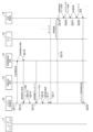
- FIG. 8 is a sequence diagram illustrating processing executed by the autonomous mobile body control system according to the first embodiment
- FIG. 9 is a sequence diagram following FIG. 8
- FIG. 10 is a sequence diagram following FIG. is.
- 8 to 10 show the processing executed by each device from when the user inputs position information to the user interface 11 until the current position information of the autonomous mobile body 12 is received. 8 to 10 are executed by the computers in the control units 10 to 15 executing the computer programs stored in the memory.
- step S201 the user uses the user interface 11 to access the WEB page provided by the system control device 10.
- step S202 the system control device 10 displays the position input screen as described with reference to FIG. 2 on the display screen of the WEB page.
- step S203 as described with reference to FIG. 2, the user selects an autonomous mobile object (mobility) and inputs position information (hereinafter referred to as position information) indicating a departure point, a transit point, and an arrival point.
- position information position information indicating a departure point, a transit point, and an arrival point.
- the location information may be a word (hereinafter referred to as a location word) that specifies a specific location such as a building name, station name, or address, or a specific location on a map displayed on a web page as a point (hereinafter referred to as a point). It may be a method to
- step S204 the system control device 10 saves the type information of the selected autonomous mobile body 12 and the input information such as the input position information.
- the system controller 10 stores the position word.
- the system control device 10 searches for the latitude and longitude corresponding to the point based on the simple map information stored in the position/route information management unit 10-3, Store latitude and longitude.
- step S205 the system control device 10 designates the type of route that can be moved (hereinafter referred to as route type) from the mobility type (moving body type) of the autonomous mobile body 12 designated by the user. Then, in step S206, it is transmitted to the route determination device 13 together with the positional information.
- route type the type of route that can be moved
- the type of mobility is, for example, a legally distinguished type of mobile object, such as a car, bicycle, or drone.
- the route types are, for example, general roads, expressways, motorways, predetermined sidewalks, roadside strips of general roads, and bicycle lanes.
- the route type is specified as a general road, a highway, a motorway, or the like.
- the mode of mobility is a bicycle, a predetermined sidewalk, a side strip of a general road, a bicycle lane, etc. are specified.
- step S207 the route determination device 13 inputs the received positional information into the owned map information as a departure point, a transit point, and an arrival point. If the positional information is a positional word, a search (preliminary search) is performed using the map information using the positional word, and the relevant latitude/longitude information is input. If the position information is latitude/longitude information, it is used by inputting it into the map information as it is. Furthermore, the route determination device 13 may search for routes in advance.
- step S208 the route determination device 13 searches for a route from the departure point to the arrival point via the intermediate points.
- the route to be searched is searched according to the route type. If a route has been searched in advance in step S208, the route searched in advance is appropriately changed based on the route type.
- step S209 the route determination device 13 outputs, as a result of the search, a route from the departure point to the arrival point via the waypoints (hereinafter referred to as route information) in GPX format (GPS eXchange Format), and system control is performed.
- route information a route from the departure point to the arrival point via the waypoints
- GPX format GPS eXchange Format
- GPX format files are mainly divided into three types: waypoints (point information without order), routes (point information with order with time information added), and tracks (collection of multiple point information: trajectory). is configured to
- latitude/longitude are described as attribute values of each point information, altitude, geoid height, GPS reception status/accuracy, etc. are described as child elements.
- the minimum element required for a GPX file is latitude/longitude information for a single point, and any other information is optional.
- a route is output as route information, and is a set of point information consisting of latitude/longitude having an order relationship. Note that the route information may be in another format as long as it satisfies the above requirements.
- FIG. 11(A) is a diagram showing latitude/longitude information of the earth
- FIG. 11(B) is a perspective view showing the predetermined space 100 in FIG. 11(A).
- the center of the predetermined space 100 is defined as the center 101.
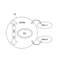
- FIG. 12 is a diagram schematically showing spatial information in the space 100. As shown in FIG.
- the format divides the three-dimensional space of the earth into spaces for each predetermined unit volume determined by the range starting from latitude/longitude/height.
- a unique identifier is added to the space to make it manageable.
- the space 100 is displayed as a predetermined three-dimensional space.
- a space 100 is defined by a center 101 of 20 degrees north latitude, 140 degrees east longitude, and height (altitude, altitude) H, and the width in the latitudinal direction is defined as D, the width in the longitudinal direction as W, and the width in the height direction as T. is a partitioned space. In addition, it is one space obtained by dividing the space of the earth into spaces determined by ranges starting from latitude/longitude/height. Incidentally, such divided space 100 is called a voxel (VOXEL).
- each of the arranged divided spaces has its horizontal position defined by latitude/longitude, overlaps in the height direction, and the position in the height direction is defined by height.
- the center 101 of the divided space is set as the starting point of latitude/longitude/height in FIG. 11B, the starting point is not limited to this. It is good as Also, the shape may be a substantially rectangular parallelepiped, and when considering the case of laying on a spherical surface such as the earth, it is better to set the top surface of the rectangular parallelepiped slightly wider than the bottom surface, so that it can be arranged without gaps.
- information on the types of objects that exist or can enter the range of the space 100 and time limits are associated with unique identifiers.
- the formatted spatial information is stored in chronological order from the past to the future. Note that, in the present embodiment, associating and linking are used in the same meaning.
- the conversion information holding device 14 associates with the unique identifier the spatial information regarding the types of objects that can exist or can enter a three-dimensional space defined by latitude/longitude/height and the time limit, and formats the format database 14-. Saved in 4.
- the spatial information is updated at predetermined update intervals based on information supplied by information supply means such as an external system (for example, the sensor node 15) communicatively connected to the conversion information holding device 14. Then, the information is shared with other external systems communicably connected to the conversion information holding device 14 . For applications that do not require time-related information, it is possible to use spatial information that does not contain time-related information. Also, non-unique identifiers may be used instead of unique identifiers.
- information about the type of an object that can exist or enter a three-dimensional space defined by latitude/longitude/height and the time limit (hereinafter referred to as spatial information) is associated with a unique identifier. formatted and stored in the database. Space-time can be managed by formatted spatial information.
- the conversion information holding device 14 of the first embodiment executes a formatting step of formatting and saving information about update intervals of spatial information in association with unique identifiers.
- the update interval information formatted in association with the unique identifier may be the update frequency, and the update interval information includes the update frequency.
- step S210 the system control device 10 confirms the interval between each piece of point information in the received route information. Then, the position point group data is created by matching the interval of the point information with the interval between the starting point positions of the divided spaces defined by the format.
- the system control device 10 thins out the point information in the route information according to the interval of the starting point positions of the divided spaces, and uses it as position point cloud data. do. Also, if the interval of point information is larger than the interval between the starting point positions of the divided spaces, the system control device 10 interpolates the point information within a range that does not deviate from the route information to obtain position point group data.
- step S211 in Fig. 9 the system control device 10 transmits the latitude/longitude information of each point information of the position point cloud data to the conversion information holding device 14 in the order of the route.
- step S212 the conversion information holding device 14 searches the format database 14-4 for a unique identifier corresponding to the received latitude/longitude information, and transmits it to the system control device 10 in step S213.
- step S214 the system control device 10 arranges the received unique identifiers in the same order as the original position point cloud data, and stores them as route information using the unique identifiers (hereinafter referred to as format route information).
- the system control device 10 as the route generation means acquires the spatial information from the database of the conversion information holding device 14, and based on the acquired spatial information and the type information of the mobile object, Generating route information about travel routes.
- FIG. 13(A) is an image diagram of route information displayed as map information
- FIG. 13(B) is an image diagram of route information using position point cloud data displayed as map information
- FIG. 13(C) is an image diagram using unique identifiers.
- FIG. 10 is an image diagram showing route information as map information;
- 120 is route information
- 121 is a non-movable area through which the autonomous mobile body 12 cannot pass
- 122 is a movable area where the autonomous mobile body 12 can move.
- the route information 120 generated by the route determining device 13 based on the positional information of the departure point, waypoints, and arrival points designated by the user passes through the departure point, waypoints, and arrival points, and is displayed on the map information. It is generated as a route passing over the movable area 122 .
- 123 is a plurality of pieces of position information on route information. After acquiring the route information 120 , the system control device 10 generates position information 123 arranged at predetermined intervals on the route information 120 .
- the position information 123 can be represented by latitude/longitude/height, respectively, and this position information 123 is called position point cloud data in the first embodiment. Then, the system control device 10 transmits the position information 123 (latitude/longitude/height of each point) one by one to the conversion information holding device 14 and converts them into unique identifiers.
- 124 is positional space information in which the positional information 123 is converted into a unique identifier one by one, and the spatial range defined by the unique identifier is represented by a rectangular frame.
- the location space information 124 is obtained by converting the location information into a unique identifier.
- the route represented by the route information 120 is converted into continuous position space information 124 and represented.
- Each piece of position space information 124 is associated with information about the types of objects that can exist or enter the space and the time limit. This continuous position space information 124 is called format route information in the first embodiment.
- step S215 the system control device 10 downloads the spatial information associated with each unique identifier of the format path information from the conversion information holding device 14.
- step S216 the system control device 10 converts the space information into a format that can be reflected in the three-dimensional map of the cyberspace of the autonomous mobile body 12, and information indicating the positions of multiple objects (obstacles) in the predetermined space.
- the cost map may be created with respect to the space of all routes in the format route information at first, or may be created in a form divided by fixed areas and updated sequentially.
- step S217 the system control device 10 associates the format route information and the cost map with the unique identification number (unique identifier) assigned to the autonomous mobile body 12 and stores them.
- the autonomous mobile body 12 monitors (hereinafter, polling) its own unique identification number via the network at predetermined time intervals, and downloads the associated cost map in step S218.
- the autonomous mobile body 12 reflects the latitude/longitude information of each unique identifier of the format route information as route information on the three-dimensional map of cyberspace created by itself.
- step S220 the autonomous mobile body 12 reflects the cost map on the three-dimensional map of cyberspace as obstacle information on the route. If the cost map is created in a form that is divided at regular intervals, after moving the area in which the cost map was created, download the cost map of the next area and update the cost map.
- step S221 the autonomous mobile body 12 moves along the route information while avoiding the objects (obstacles) entered in the cost map. That is, movement control is performed based on the cost map.
- step S222 the autonomous mobile body 12 moves while performing object detection, and moves while updating the cost map using the object detection information if there is a difference from the cost map. Also, in step S223, the autonomous mobile body 12 transmits difference information from the cost map to the system control device 10 together with the corresponding unique identifier.
- the system control device 10 that has acquired the difference information between the unique identifier and the cost map transmits the spatial information to the conversion information holding device 14 in step S224 of FIG. Update the spatial information of the unique identifier.
- the content of the spatial information updated here does not directly reflect the difference information from the cost map, but is abstracted by the system control device 10 and then sent to the conversion information holding device 14 . Details of the abstraction will be described later.
- step S226 the autonomous mobile body 12 moving based on the format route information informs the system controller 10 of the space it is currently passing through each time it passes through the divided space associated with each unique identifier. Send the associated unique identifier.
- the system control device 10 grasps the current position of the autonomous mobile body 12 on the format route information.
- the system control device 10 can grasp where the autonomous mobile body 12 is currently located in the format route information. Incidentally, the system control device 10 may stop holding the unique identifier of the space through which the autonomous mobile body 12 has passed, thereby reducing the holding data capacity of the format route information.
- step S227 the system control device 10 creates the confirmation screen 50 and the map display screen 60 described with reference to FIGS. do.
- the system control device 10 updates the confirmation screen 50 and the map display screen 60 each time a unique identifier indicating the current position is transmitted from the autonomous mobile body 12 to the system control device 10 .
- the sensor node 15 saves the detection information of the detection range, abstracts the detection information in step S229, and transmits it as spatial information to the conversion information holding device 14 in step S230. Abstraction is information such as whether or not an object exists, or whether or not the state of existence of the object has changed, and is not detailed information about the object.
- step S231 the conversion information holding device 14 stores the spatial information, which is the abstracted detection information, in association with the unique identifier of the position corresponding to the spatial information. This results in spatial information being stored in one unique identifier in the format database.
- the external system uses the spatial information in the conversion information holding device 14 to obtain the detected information in the sensor node 15 via the conversion information holding device 14. is obtained and utilized.
- the conversion information holding device 14 also has a function of connecting the communication standards of the external system and the sensor node 15 .
- the conversion information holding device 14 has a function of connecting data of multiple devices with a relatively small amount of data.
- steps S215 and S216 of FIG. 9 when the system control device 10 needs detailed object information when creating a cost map, detailed information is sent from an external system storing detailed detection information of spatial information. should be downloaded and used.
- the sensor node 15 updates the spatial information on the route of the format route information of the autonomous mobile body 12 .
- the sensor node 15 acquires detection information in step S232 of FIG. 10, generates abstracted spatial information in step S233, and transmits it to the conversion information holding device 14 in step S234.
- the conversion information holding device 14 stores the spatial information in the format database 14-4 in step S235.
- the system control device 10 checks changes in the spatial information in the managed format path information at predetermined time intervals, and downloads the spatial information in step S236 if there is a change. Then, in step S237, the cost map associated with the unique identification number assigned to the autonomous mobile body 12 is updated. In step S238, the autonomous mobile body 12 recognizes the update of the cost map by polling, and reflects it on the three-dimensional map of the cyberspace created by itself.
- the autonomous mobile body 12 can recognize in advance changes in the route that the autonomous mobile body 12 cannot recognize, and can respond to such changes.
- a unique identifier is transmitted in step S240.
- the system control device 10 Upon recognizing the unique identifier, the system control device 10 displays an arrival indication on the user interface 11 in step S241, and terminates the application. According to Embodiment 1, as described above, it is possible to provide a digital architecture format and an autonomous mobile body control system using the same.
- the format database 14-4 stores information (spatial information) about the types of objects that can exist or enter the space 100 and the time limit from the past. It is stored in chronological order such as the future. Further, the spatial information is updated based on information input from an external sensor or the like communicably connected to the conversion information holding device 14, and can be connected to the conversion information holding device 14 via a network by wired communication or wireless communication. Information is shared with other external systems.
- the type information of objects in the space is information that can be obtained from map information, such as roadways, sidewalks, and bicycle lanes on roads.
- map information such as roadways, sidewalks, and bicycle lanes on roads.
- information such as the traveling direction of mobility on a roadway, traffic regulations, etc. can also be defined as type information.
- type information it is also possible to define type information in the space itself.
- the conversion information holding device 14 can be connected to a system control device that manages information on roads and a system control device that manages information on sections other than roads.
- the system control device 10 can transmit position point cloud data collectively representing the position information 123 of FIG. Similarly, a system control device that manages information on roads and a system control device that manages information on sections other than roads can also transmit corresponding data to the conversion information holding device 14 .
- the corresponding data is the position point cloud data information managed by the system control device that manages road information and the system control device that manages information on sections other than roads.
- Each point of the position point cloud data is hereinafter referred to as a position point.
- the space information update interval differs according to the type of object existing in the space. That is, when the type of object existing in the space is a moving object, the length of time is set to be shorter than when the type of object existing in the space is not a moving object. Also, when the type of the object existing in the space is a road, the type of the object existing in the space is made shorter than in the case of the partition.
- the update interval of the space information about each object should be different according to the type of each object (eg moving body, road, section, etc.). Spatial information about the state and time of each of a plurality of objects existing in the space is associated with the unique identifier, formatted and stored. Therefore, the load for updating spatial information can be reduced.
- spatial information is associated with a cubic voxel (VOXEL) of each divided space region obtained by dividing the space region of the real world.
- Spatial information may be associated with and stored in three-dimensional spatial regions having various shapes such as rectangular parallelepiped shapes, polygonal polygon shapes, and spherical shapes in addition to cubic shapes.
- the autonomous mobile bodies for which spatial information is used include various types/ A size is assumed.
- the spatial information linked to the voxels of each divided space area in the format database 14-4 it is possible to determine an appropriate movement route of the autonomous mobile body.
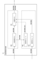
- FIG. 14 is a block diagram showing an internal configuration example of the conversion information holding device 14.
- the conversion information holding device 14 includes a temporary memory 200, a working memory 201, and storages 202 and 203 for saving.
- the temporary storage memory 200 and the work memory 201 are memories suitable for high-speed processing that can be written and read at high speed compared to the storage storages 202 and 203 .
- the storage storages 202 and 203 are slow in writing and reading (input/output) compared to the temporary storage memory 200 and the working memory 201, and are not suitable for high-speed processing, but they are large-capacity storages. be.
- the temporary storage memory 200 functions as first storage means for performing a first storage step of storing static information in spatial information.
- the storage for storage 203 functions as a second storage means for performing a second storage step of storing dynamic information in the spatial information.
- the temporary storage memory 200, which is the first storage means has an input/output speed lower than that of the storage storage 203, which is the second storage means.
- the temporary storage memory 200 and the working memory 201 are composed of memories with relatively high manufacturing costs per storage capacity
- the storage storages 202 and 203 are composed of memories with relatively low manufacturing costs per storage capacity. be done.
- the temporary storage memory 200 and the working memory 201 are composed of, for example, RAM (Random Access Memory) such as DRAM (Dynamic RAM) and SRAM (Static RAM), which are volatile memories. Volatile memory loses its data when the power is turned off.
- RAM Random Access Memory
- DRAM Dynamic RAM
- SRAM Static RAM
- the storage storages 202 and 203 are configured by ROM (Read Only Memory) such as EPROM (Erasable Programmable ROM) and EEPROM (Electrically EPROM), which are non-volatile memories, for example.
- ROM Read Only Memory
- EPROM Erasable Programmable ROM
- EEPROM Electrical EPROM
- Non-volatile memory retains its data even when the power is turned off.
- the storages 202 and 203 for preservation may be composed of flash memory, SSD (Solid State Drive), HDD (Hard Disk Drive), or the like.
- the temporary storage memory 200, working memory 201, and storage storages 202 and 203 are arranged, for example, in the format database 14-4 shown in FIG.
- the temporary storage memory 200 and the work memory 201 may be composed of one integrated memory, or may be composed of two or more divided storage areas within the same memory.
- the storages 202 and 203 may be configured as one integrated storage, and configured as two or more divided storage areas within the same storage.
- Either or both of the temporary storage memory 200 and the working memory 201 may be arranged in the information storage section 14-5. Either or both of the temporary storage memory 200 and the working memory 201 may be arranged in the control unit 14-3.
- Spatial information consists of dynamic information such as information on the presence of vehicles and pedestrians, information on the status of traffic lights (red/blue (green)/yellow), and static information such as information on road surfaces and the presence of structures.
- dynamic information and semi-dynamic information (semi-dynamic information) defined by a dynamic map are handled as dynamic information in this embodiment
- static information and semi-static information (semi-static information) defined by a dynamic map are treated as dynamic information in this embodiment.
- static information is treated as static information in this embodiment.
- the dynamic information in the dynamic map includes, for example, information transmitted/exchanged between moving objects, traffic signal display information, pedestrian/bicycle information at intersections, information on vehicles going straight through intersections, etc., and the update frequency in units of one second can be obtained.
- semi-dynamic information can be obtained within one minute at the time of observation, such as actual traffic congestion, temporary driving restrictions, temporary driving obstacles such as falling objects and disabled people, actual accident conditions, and narrow-area weather information. It refers to information for which the update frequency of is required.
- quasi-static information refers to information that requires an update frequency within one hour, such as traffic control information due to road construction or events, wide-area weather information, and traffic congestion forecasts.
- Static information is information that is required to be updated within one month, such as roads, structures on roads, lane information, road surface information, and permanent regulation information. So to speak, it refers to the map information that is the base of the dynamic map.
- dynamic information, semi-dynamic information, and semi-static information defined in the dynamic map are treated as dynamic information in this embodiment, and static information defined in the dynamic map is treated as static information in this embodiment. may be treated as information.
- the dynamic information defined by the dynamic map is handled as the dynamic information in this embodiment, and the semi-dynamic information, semi-static information, and static information defined in the dynamic map are treated as the static information in this embodiment. may be treated as information.
- the update frequency has a relationship of dynamic information>semi-dynamic information>semi-static information>static information
- the dynamic information is stored in the temporary storage memory 200 suitable for high-speed processing.
- the static information since the static information has the lowest update frequency, it is not stored in the temporary storage memory 200 but stored in the storage storage 203 . As a result, use of the storage area of the temporary storage memory 200 is suppressed.
- the dynamic information is stored in the temporary memory 200, it is also stored in the storage storage 202 so that the past situation can be investigated in the event of an accident or the like.
- the received dynamic information may be stored in the temporary storage memory 200 and concurrently stored directly in the storage storage 202 without going through the temporary storage memory 200 .
- the working memory 201 temporarily stores dynamic information read from the temporary memory 200 or the storage storage 202 and static information read from the storage storage 203 . Then, the dynamic information and static information that have undergone integration processing in the working memory 201 are transmitted to the system control device 10 or the like via the network connection unit 14-6 as communication means.
- the working memory 201 functions as a third storage means that reads, integrates and stores the respective spatial information stored in the first storage means and the second storage means. It also functions as integrated spatial information generating means for performing an integrated spatial information generating step for generating integrated spatial information.
- the control unit 14-3 controls the writing and reading of dynamic information and static information to/from the memory/storage.
- the dynamic information stored in the temporary storage memory 200 is deleted sequentially from the oldest information when the usage capacity of the temporary storage memory 200 exceeds a predetermined limit value.
- the system control device 10 downloads the spatial information from the conversion information holding device 14, converts it into a format that can be reflected in the three-dimensional map of the cyber space of the autonomous mobile body 12, and converts it into a predetermined Create a cost map in space. Then, the autonomous mobile body 12 downloads the cost map at predetermined time intervals and performs movement control based on the cost map.
- the spatial information is downloaded from the conversion information holding device 14.
- the spatial information includes static information and dynamic information, which are stored in different storage areas of the conversion information holding device 14. stored.
- the cost map necessary for controlling the movement of the autonomous mobile body 12 is created by combining these static information and dynamic information. A specific method of creating this cost map will be described with reference to FIGS. 15 to 20.
- FIG. Here, the object of movement control is assumed to be the autonomous mobile body 12 shown in FIG.
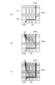
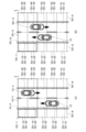
- FIGS. 15A and 15B are diagrams showing examples of the state of the roadway and its surrounding space, showing the state of looking down from above on the roadway 701-5 with one lane in each direction, its surroundings, and its space. ing.
- the upper side of the paper faces the north direction.
- Spaces 701-21 to 701-25 and 701-31 to 701-35 are spaces on the roadway 701-5, and the mobile body moves through these spaces.
- a building 701-7 exists in the spaces 701-14 and 701-15.
- FIG. 15(A) the mobile object 701-4 exists in the spaces 701-34 and 701-35, and the mobile object 701-4 is moving southward in the figure. After a certain period of time, the moving body 701-4 moves to the spaces 701-33 and 701-34 as shown in FIG. 15(B).
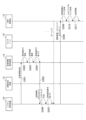
- FIG. 16 is a sequence diagram illustrating processing executed by the autonomous mobile control system according to the embodiment. Each step of the sequence shown in FIG. 16 is performed by the CPU as a computer in the control units 10, 12 to 15 executing the computer program stored in the memory.
- the cost map creation range in this embodiment is a predetermined range 701-8 in the course direction of the autonomous mobile body 12 in FIG.
- step S301 the system control device 10 transmits the position information of the predetermined range 701-8 in the course direction of the autonomous mobile body 12 to the conversion information holding device .
- the location information includes latitude/longitude information and the like of each point information of the location point cloud data.
- step S302 the conversion information holding device 14 searches the format database 14-4 for a unique identifier corresponding to the received latitude/longitude information. Then, in step S303, the conversion information holding device 14 reads out the spatial information associated with each unique identifier from the temporary storage memory 200 and the storage storage 203, copies it, and stores it in the working memory 201.
- FIG. 1 the conversion information holding device 14 searches the format database 14-4 for a unique identifier corresponding to the received latitude/longitude information.
- the spaces indicated by the unique identifier in the predetermined range 701-8 in the course direction of the autonomous mobile body 12 are spaces 701-14, 701-15, 701-24, 701-25, 701-34, 701-35. , 701-44 and 701-45. Get information about these spaces.
- objects such as a moving object 701-4, a roadway 701-5, a sidewalk 701-6, and a building 701-7 exist in these spaces.
- static objects such as the roadway 701-5, the sidewalk 701-6, and the building 701-7 are stored in the storage storage 203 as space static information for each unique identifier corresponding to the latitude/longitude information of each space.
- a moving object such as the moving object 701-4 is stored in the temporary storage memory 200 as spatial dynamic information for each unique identifier corresponding to the latitude/longitude information of each space.
- step S303 the conversion information holding device 14 integrates each piece of spatial information copied to the working memory 201 in step S304, associates it with each corresponding unique identifier, and transmits it to the system control device 10 in step S305. .
- step S306 the system control device 10 converts the acquired integrated space information into a format that can be reflected in the three-dimensional map of the cyber space of the autonomous mobile body 12, and the predetermined range 701-8 Create a cost map.
- the system control device 10 functions as control means for creating a cost map regarding movement control of moving bodies based on the integrated spatial information.
- FIG. 17 is a diagram showing a predetermined range 701-8 in the forward field of view of the autonomous mobile body 12 in the state of FIG. 15(A).
- spaces 701-14 and 701-15 where buildings 701-7 exist spaces 701-34 and 701-35 where moving objects 701-4 exist, and spaces 701-44 and 701 where sidewalks 701-6 exist.
- -45 is a space in which an obstacle may exist when the autonomous mobile body 12 moves. In other words, these spaces are recognized as costs, and can be represented as hatched lines in FIG. 17 when illustrated as a cost map.
- step S307 of FIG. 16 the system control device 10 associates (associates) the format route information and the cost map with the unique identification number assigned to the autonomous mobile body 12 and stores them.
- the autonomous mobile body 12 monitors (hereinafter, polls) its own unique identification number via the network at predetermined time intervals, and downloads the associated cost map in step S308.
- step S309 the autonomous mobile body 12 reflects the latitude/longitude information of each unique identifier of the format route information as route information on the three-dimensional map of cyberspace created by itself.
- step S310 the autonomous mobile body 12 reflects the cost map on the three-dimensional map of cyberspace as obstacle information on the route.
- the autonomous mobile body 12 moves along the route information while avoiding objects (obstacles) input in the cost map. That is, movement control is performed based on the cost map. Specifically, in FIG. 17, the autonomous mobile body 12 can move through spaces 701-24 and 701-25.
- static information and dynamic information data are acquired from the conversion information holding device 14, and the system control device generates a cost map.
- the spatial information of the dynamic information changes its state sequentially every second, for example.
- the state of spatial information of static information such as buildings hardly changes. Therefore, in updating the once generated cost map, it is desirable to update only the spatial information of the dynamic information from the viewpoint of the processing load of the conversion information holding device 14 in step S303 and the network load in information transmission in step S308. .
- FIG. 18 is a sequence diagram for explaining the method of creating a cost map and updating the cost map. Based on FIG. explain. The steps of the sequence shown in FIG. 18 are performed by the CPU as a computer in the control units 10, 12 to 15 executing the computer program stored in the memory.
- step S321 the system control device 10 transmits the position information of the predetermined range 701-8 in the course direction of the autonomous mobile body 12 to the conversion information holding device .
- the location information includes latitude/longitude information and the like of each point information of the location point cloud data.
- acquisition classification information indicating whether to acquire static information and dynamic information of each space corresponding to the predetermined range 701-8 or to acquire only dynamic information is sent together.
- the system control device 10 has created a cost map in the predetermined range 701-8, only dynamic information is acquired, and if no cost map has been created, static information and dynamic information are acquired. Send the acquisition classification information so as to acquire .
- the acquired classification information is G1 when static information and dynamic information of each space are acquired, and G0 when only dynamic information is acquired.
- step S322 the conversion information holding device 14 searches each unique identifier corresponding to the received latitude/longitude information from the format database 14-4. After that, if the acquired classification information is G1, the conversion information holding device 14 copies the spatial data from the temporary storage memory 200 and the storage storage 203 to the working memory 201 in step S323.
- steps S323 and S324 may be performed in parallel as shown in FIG. 18, or may be performed sequentially.
- the conversion information holding device 14 links each piece of spatial information copied to the working memory 201 in step S325 with each corresponding unique identifier, and transmits it to the system control device 10 in step S326.
- step S327 the system control device 10 converts the acquired space information into a format that can be reflected in the three-dimensional map of the cyber space of the autonomous mobile body 12, and the predetermined Create a cost map for range 701-8.
- step S328 only the acquired space information is updated for the cost map of the predetermined range 701-8.
- steps S327 and S328 may be performed in parallel as shown in FIG. 18, or may be performed sequentially.
- the spatial information of the spaces 701-34 and 701-35 in which the moving body 701-4 is present which is dynamic information, is obtained, and the cost map of the predetermined range 701-8 is calculated for the spaces 701-34 and 701- 35 information is updated.
- the moving object 701-4 remains in the space 701-34 while the moving object 701-4 no longer exists in the space 701-35.
- step S329 the system control device 10 associates the format route information and the cost map with the unique identification number assigned to the autonomous mobile body 12 and stores them.
- the autonomous mobile body 12 monitors (hereinafter, polls) its own unique identification number via the network at predetermined time intervals, and downloads the associated cost map in step S330.
- step S331 the autonomous mobile body 12 reflects the latitude/longitude information of each unique identifier of the format route information as route information on the three-dimensional map of cyberspace created by itself.
- step S332 the autonomous mobile body 12 reflects the cost map on the three-dimensional map of cyberspace as obstacle information on the route.
- step S333 the autonomous mobile body 12 moves along the route information while avoiding objects (obstacles) input in the cost map. That is, autonomous movement control is performed based on the cost map.
- the data of static information and dynamic information, or only the data of dynamic information is acquired from the conversion information holding device 14, and based on these information, the system control device generates a cost map Generate and update the .
- the system control device 10 generates and updates the cost map required for movement control of the autonomous mobile body 12.
- the cost map is generated and updated using the conversion information. An example performed by the holding device 14 will be described.
- FIG. 19 is a block diagram showing an internal configuration example of the conversion information holding device 14 according to the second embodiment.
- a first cost map 205 and a second cost map 206 are generated in working memory 201 .
- a first cost map 205 and a second cost map 206 are generated based on information in the temporary storage memory 200 and storage storage 202, respectively.
- the working memory 201 as integrated spatial information generating means can hold a plurality of cost maps.
- the first cost map 205 is a cost map to be used for movement control of the autonomous mobile body 12a.
- the second cost map 206 is a cost map for use in movement control of, for example, the autonomous mobile body 12b traveling on a sidewalk.
- the autonomous mobile body 12a is, for example, an automatic driving car that moves on a roadway
- the autonomous mobile body 12b is, for example, a parcel delivery robot that moves on a sidewalk.
- a moving body moving on a sidewalk roadways, other moving bodies, and buildings are determined as costs, and sidewalks are not determined as costs. That is, the cost map is made different according to the type of the autonomous mobile body and the place of travel. In this way, a cost map is generated that indicates whether or not the autonomous mobile body can pass through depending on the type of the autonomous mobile body and the travel location.
- FIG. 20 is a flowchart for explaining processing executed by the conversion information holding device 14 according to the second embodiment. 20 is performed by the CPU of the control section 14-3 of the conversion information holding device 14 executing the computer program stored in the memory.
- step S353 the control unit 14-3 creates a cost map within a predetermined space based on these pieces of information. Furthermore, in step S354, the control unit 14-3 determines whether or not a predetermined time T1 has elapsed.
- the predetermined time T1 is the elapsed time (period) from the creation of the cost map and the update of the static information of the cost map, for example several days. This is because static information such as buildings does not change in a short period of time.
- step S354 the process proceeds to step S357.
- the control unit 14-3 waits until a predetermined time T2 elapses.
- the predetermined time T2 is the elapsed time from the creation of the cost map and the update of the dynamic information of the cost map, and is, for example, several seconds. This is because there is a possibility that dynamic information such as a moving object changes its position in a short period of time.
- step S356 the cost map within the predetermined space is updated. If it is determined in step S359 that the cost map does not need to be updated in the future, this process ends. If not, the process returns to step S354 and continues.
- the static information and the dynamic information are acquired when the predetermined time T1 or the predetermined time T2 has passed, but it is not limited to this.
- Embodiment 2 the creation and updating of the first cost map for the autonomous mobile body 12a of FIG. 19 has been described using the flowchart of FIG. 20, but the creation and updating of the second cost map of FIG. can be implemented.
- a cost map for drone operations may be created.
- a plurality of cost maps are created in the conversion information holding device 14, but a plurality of cost maps may be created in the system control device 10, for example.
- Embodiments 1 and 2 in an autonomous mobile control system using spatial information in a three-dimensional space defined by latitude/longitude/height, static information is stored in a relatively low-speed storage storage. , and dynamic information is stored in relatively fast temporary memory. Therefore, network traffic and data processing load can be optimized.
- data input/output can be speeded up when high-speed access is required according to the position indicated by the unique identifier.
- the cost map is created from the static information and dynamic information stored in each storage location, the necessary data can be stored with low latency without high-speed access to all data. can be pulled out.
- cost maps are created according to the type of mobile object, a more appropriate cost map can be created.
- the cost map is created based on static information and dynamic information, and the cost map is updated based on the dynamic information, efficiency can be improved.
- the cost map may be created by using relatively distant information from a relatively low speed storage storage and relatively near information from a relatively high speed temporary storage memory. . That is, the static information may include spatial information relatively farther than the dynamic information.
- the area where the state changes frequently creates a cost map with information from a relatively high-speed temporary storage memory, and the road information and structure information between intersections are created.
- a cost map may be created with information from relatively slow storage storage.
- the size of the cost map creation range in this embodiment is not limited to a fixed value. , can be of any size. That is, there may be a plurality of sizes of cost maps relating to movement control of the moving body.
- the size of the cost map creation range may be changed depending on the mobile object.
- the first cost map for the autonomous mobile body 12a that moves on the roadway and the second cost map for the autonomous mobile body 12b that moves on the sidewalk are created.
- the moving speed of the moving object (cost object) moving on the roadway is relatively faster than the moving speed of the moving object (cost object) moving on the sidewalk.
- the size of the cost map may differ depending on the moving object whose movement is controlled.
- the size of the cost map creation range may be changed according to the position in space.
- the cost map creation range is enlarged, and for areas with a low possibility of changing conditions (such as other mobile narrow alleys, etc.), the cost map creation range may be reduced. That is, the size of the cost map may differ depending on the position in the three-dimensional space defined by latitude/longitude/height.
- the moving object will acquire cost information over a wider range to ensure that it moves while avoiding objects (obstacles such as people and other vehicles).
- objects obstacles such as people and other vehicles.
- the size of the cost map creation range may be changed according to the moving speed of the moving object that uses the cost map.
- the cost map creation range may be widened. That is, the size of the cost map may differ depending on the moving speed of the moving object.
- the mobile object of this embodiment is not limited to an autonomous mobile object such as an AGV (Automatic Guided Vehicle) or an AMR (Autonomous Mobile Robot).
- AGV Automatic Guided Vehicle
- AMR Automatic Mobile Robot
- it can be any mobile device that moves, such as automobiles, trains, ships, airplanes, robots, and drones.
- part of the control system of the present embodiment may or may not be mounted on those moving bodies.
- this embodiment can be applied to remote control of a moving object.
- the present invention may be realized by supplying a storage medium recording software program code (control program) for realizing the functions of the above-described embodiments to a system or apparatus. It is also achieved by the computer (or CPU or MPU) of the system or apparatus reading and executing the computer-readable program code stored in the storage medium.
- control program software program code
- the program code itself read from the storage medium implements the functions of the above-described embodiments, and the storage medium storing the program code constitutes the present invention.
Abstract
L'invention concerne un système de commande qui est capable de générer des informations spatiales intégrées à l'aide d'informations statiques et d'informations dynamiques dans un espace tridimensionnel, le système de commande comprenant : un moyen de formatage destiné à formater des informations concernant un objet présent dans un espace tridimensionnel défini par la latitude, la longitude et l'altitude en tant qu'informations spatiales en association avec un identifiant unique; un premier moyen de stockage destiné à stocker des informations statiques parmi les informations spatiales; un second moyen de stockage destiné à stocker des informations dynamiques parmi les informations spatiales; et un moyen de génération d'informations spatiales intégrées pour lire les informations spatiales respectives stockées par le premier moyen de stockage et le second moyen de stockage, et pour générer des informations spatiales intégrées.
Applications Claiming Priority (6)
| Application Number | Priority Date | Filing Date | Title |
|---|---|---|---|
| JP2022014166 | 2022-02-01 | ||
| JP2022-014166 | 2022-02-01 | ||
| JP2022123097 | 2022-08-02 | ||
| JP2022-123097 | 2022-08-02 | ||
| JP2023000491A JP2023112665A (ja) | 2022-02-01 | 2023-01-05 | 制御システム、制御方法、及びコンピュータプログラム |
| JP2023-000491 | 2023-01-05 |
Publications (1)
| Publication Number | Publication Date |
|---|---|
| WO2023149264A1 true WO2023149264A1 (fr) | 2023-08-10 |
Family
ID=87552163
Family Applications (1)
| Application Number | Title | Priority Date | Filing Date |
|---|---|---|---|
| PCT/JP2023/001934 WO2023149264A1 (fr) | 2022-02-01 | 2023-01-23 | Système de commande, procédé de commande et support de stockage |
Country Status (1)
| Country | Link |
|---|---|
| WO (1) | WO2023149264A1 (fr) |
Citations (5)
| Publication number | Priority date | Publication date | Assignee | Title |
|---|---|---|---|---|
| JP2017068639A (ja) * | 2015-09-30 | 2017-04-06 | セコム株式会社 | 自律移動ロボット |
| WO2018083999A1 (fr) * | 2016-11-01 | 2018-05-11 | パナソニック インテレクチュアル プロパティ コーポレーション オブ アメリカ | Procédé d'affichage, et dispositif d'affichage |
| WO2019167457A1 (fr) * | 2018-02-28 | 2019-09-06 | ソニー株式会社 | Dispositif de traitement d'informations, procédé de traitement d'informations, programme et corps mobile |
| JP2019176311A (ja) * | 2018-03-28 | 2019-10-10 | 住友電気工業株式会社 | 車載装置、その制御方法及びコンピュータプログラム |
| JP2020178311A (ja) * | 2019-04-22 | 2020-10-29 | キヤノン株式会社 | 通信装置、制御方法およびプログラム |
-
2023
- 2023-01-23 WO PCT/JP2023/001934 patent/WO2023149264A1/fr unknown
Patent Citations (5)
| Publication number | Priority date | Publication date | Assignee | Title |
|---|---|---|---|---|
| JP2017068639A (ja) * | 2015-09-30 | 2017-04-06 | セコム株式会社 | 自律移動ロボット |
| WO2018083999A1 (fr) * | 2016-11-01 | 2018-05-11 | パナソニック インテレクチュアル プロパティ コーポレーション オブ アメリカ | Procédé d'affichage, et dispositif d'affichage |
| WO2019167457A1 (fr) * | 2018-02-28 | 2019-09-06 | ソニー株式会社 | Dispositif de traitement d'informations, procédé de traitement d'informations, programme et corps mobile |
| JP2019176311A (ja) * | 2018-03-28 | 2019-10-10 | 住友電気工業株式会社 | 車載装置、その制御方法及びコンピュータプログラム |
| JP2020178311A (ja) * | 2019-04-22 | 2020-10-29 | キヤノン株式会社 | 通信装置、制御方法およびプログラム |
Similar Documents
| Publication | Publication Date | Title |
|---|---|---|
| CN110914777B (zh) | 用于自主车辆的高清地图以及路线存储管理系统 | |
| US10495470B2 (en) | Map having computer executable instructions embedded therein | |
| US20140358427A1 (en) | Enhancing driving navigation via passive drivers feedback | |
| CN111693055B (zh) | 道路网络变化检测和所检测的变化的本地传播 | |
| GB2413021A (en) | Navigation aid | |
| WO2023149264A1 (fr) | Système de commande, procédé de commande et support de stockage | |
| US20230206763A1 (en) | Systems and methods for determining utilization of an area for vehicle parking | |
| JP2023112665A (ja) | 制御システム、制御方法、及びコンピュータプログラム | |
| US20230150551A1 (en) | Systems and methods for determining an attention level of an occupant of a vehicle | |
| WO2023149288A1 (fr) | Dispositif de traitement d'informations, procédé de traitement d'informations et support de stockage | |
| WO2023149353A1 (fr) | Système de commande, procédé de commande et support d'enregistrement | |
| WO2023149370A1 (fr) | Système de commande, procédé de commande et support de stockage | |
| WO2023149346A1 (fr) | Dispositif de traitement d'informations, système de commande, procédé de commande, et support de stockage | |
| WO2023149292A1 (fr) | Système de traitement d'informations, procédé de commande et support de stockage | |
| WO2023149349A1 (fr) | Système de commande, procédé de commande et support de stockage | |
| WO2023149308A1 (fr) | Système de commande, procédé de commande et support d'enregistrement | |
| WO2023149373A1 (fr) | Système de commande, procédé de commande et support de stockage | |
| JP2023112672A (ja) | 情報処理装置、情報処理方法、及びコンピュータプログラム | |
| WO2023149358A1 (fr) | Système de commande, procédé de commande et support de stockage | |
| JP2023112658A (ja) | 制御システム、制御方法、及びコンピュータプログラム | |
| WO2023149376A1 (fr) | Système de commande, procédé de commande et support de stockage | |
| JP2023112666A (ja) | 制御システム、制御方法、及びコンピュータプログラム | |
| JP2023112659A (ja) | 情報処理装置、制御システム、制御方法、及びコンピュータプログラム | |
| JP2023112657A (ja) | 情報処理システム、制御方法、及びコンピュータプログラム | |
| JP2023112656A (ja) | 制御システム、制御方法、及びコンピュータプログラム |
Legal Events
| Date | Code | Title | Description |
|---|---|---|---|
| 121 | Ep: the epo has been informed by wipo that ep was designated in this application |
Ref document number: 23749580 Country of ref document: EP Kind code of ref document: A1 |