WO2023145747A1 - ステータ及びモータ - Google Patents
ステータ及びモータ Download PDFInfo
- Publication number
- WO2023145747A1 WO2023145747A1 PCT/JP2023/002167 JP2023002167W WO2023145747A1 WO 2023145747 A1 WO2023145747 A1 WO 2023145747A1 JP 2023002167 W JP2023002167 W JP 2023002167W WO 2023145747 A1 WO2023145747 A1 WO 2023145747A1
- Authority
- WO
- WIPO (PCT)
- Prior art keywords
- insulator
- teeth
- fitting portion
- stator
- fitting
- Prior art date
- Legal status (The legal status is an assumption and is not a legal conclusion. Google has not performed a legal analysis and makes no representation as to the accuracy of the status listed.)
- Ceased
Links
Images



Classifications
-
- H—ELECTRICITY
- H02—GENERATION; CONVERSION OR DISTRIBUTION OF ELECTRIC POWER
- H02K—DYNAMO-ELECTRIC MACHINES
- H02K3/00—Details of windings
- H02K3/32—Windings characterised by the shape, form or construction of the insulation
- H02K3/34—Windings characterised by the shape, form or construction of the insulation between conductors or between conductor and core, e.g. slot insulation
Definitions
- the present disclosure generally relates to stators and motors, and more particularly relates to stators including teeth and insulators covering at least a portion of the teeth, and motors including the stators.
- insulating paper is arranged on the slot walls of the teeth of the stator core constituting the motor, and coils are formed around the teeth via the insulating paper.
- recesses and protrusions are formed on at least one of the surface of the insulating paper on the side of the slot wall surface and the surface on the side of the coil.
- the concave portion serves as a cooling medium flow path.
- an electrically insulating insulator may be provided around the teeth.
- An object of the present disclosure is to provide a stator and motor that can reduce the possibility of insulator damage.
- a stator includes a plurality of annularly arranged tooth blocks.
- Each of the plurality of tooth blocks has teeth, insulators, and windings.
- the teeth extend radially.
- the insulator has electrical insulation.
- the insulator covers the teeth.
- the winding is wound around the insulator.
- the insulator includes a first surface facing the teeth.
- the tooth includes a second surface facing the insulator.
- the insulator has a first fitting portion on the first opposing surface.
- the tooth has a second fitting portion that fits with the first fitting portion on the second facing surface.
- a motor includes the stator and the rotor.
- the rotor has a rotor shaft. The rotor rotates with respect to the stator.
- the present disclosure has the advantage of reducing the possibility of insulator damage.
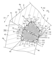
- FIG. 1 is a front cross-sectional view (described later) of a main part of a stator according to Embodiment 1.
- FIG. FIG. 2 is a front view of a motor provided with the same stator.
- FIG. 3 is a perspective view of the insulator of the stator as seen from above.
- FIG. 4 is a perspective view of the insulator of the stator as seen from below.
- FIG. 5 is a front cross-sectional view of a main part of a stator according to a first modified example.
- FIG. 6 is a front cross-sectional view of essential parts of a stator according to a second modification.
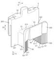
- FIG. 7 is a perspective view of the insulator of the stator according to Embodiment 2 as seen from below.
- FIG. 1 is a front cross-sectional view of a main part of a stator 3 according to Embodiment 1.
- FIG. FIG. 2 is a front view of the motor 1 including the stator 3 according to Embodiment 1.
- FIG. The front cross-sectional view is a cross-sectional view when the motor is cut along a plane perpendicular to the axial direction D3.
- the rotor shaft 21 has a cylindrical shape.
- “Axial direction” is a direction parallel to the rotation axis of the rotor shaft 21 .
- the “radial direction” is the direction from the center of the rotor shaft 21 toward the side surface of the rotor shaft 21 .
- “Circumferential” is the direction of rotation of the rotor shaft. The axial, radial and circumferential directions are orthogonal to each other.
- the stator 3 of this embodiment includes a plurality of tooth blocks TB1 arranged in a ring.
- Each of the plurality of tooth blocks TB1 has teeth 4 , insulators 5 and windings 6 .
- illustration of the insulator 5, the winding 6, and the insulating sheet 7, which will be described later, is omitted.
- the teeth 4 extend in the radial direction D2.
- the insulator 5 has electrical insulation.
- the insulator 5 covers at least part of the teeth 4 .
- Winding 6 is wound around insulator 5 .
- Insulator 5 includes a first opposing surface 5 e facing teeth 4 .
- Teeth 4 include second opposing surfaces 4 e facing insulator 5 .
- the insulator 5 has a first fitting portion G1 on the first opposing surface 5e.
- the tooth 4 has a second fitting portion P1 that fits with the first fitting portion G1 on the second opposing surface 4e.
- the contact area between the insulator 5 and the teeth 4 is larger than when the first fitting portion G1 and the second fitting portion P1 are not provided. Therefore, when pressure is applied to the insulator 5, the pressure can be relieved, and the possibility of damage to the insulator 5 can be reduced. Therefore, deterioration of the electrical insulation performance of the insulator 5 due to damage to the insulator 5 can be suppressed.
- Damage to the insulator 5 is, for example, cracking, chipping, breakage, and the like. Further, by increasing the contact area between the insulator 5 and the teeth 4, the possibility of occurrence of an abnormality in the stage prior to the damage of the insulator 5 can be reduced.
- An abnormality that precedes damage to the insulator 5 is, for example, whitening of the insulator 5 .
- Whitening of the insulator 5 is a phenomenon in which the color of the surface of the insulator 5 becomes white. Whitening of the insulator 5 occurs when a local stress is applied to the insulator 5 and the structure of the material forming the insulator 5 is deformed.
- a motor 1 includes a stator 3 and a rotor 2 .
- the rotor 2 has a rotor shaft 21 .
- Rotor 2 rotates with respect to stator 3 .
- the motor 1 may further include a motor housing. The motor housing accommodates the stator 3 and the rotor 2 .
- Rotor 2 has, for example, a rotor core 20, a rotor shaft 21, and a plurality of (six in FIG. 2) permanent magnets 22, as shown in FIG.
- the rotor core 20 is made of a magnetic material.
- the rotor core 20 has a cylindrical shape.
- the rotor core 20 has a first through hole at its center through which the rotor shaft 21 is passed. Further, the rotor core 20 has a plurality of second through holes around the first through holes, into which a plurality of permanent magnets 22 are inserted.
- the plurality of permanent magnets 22 are arranged radially around the rotor shaft 21 when viewed from the axial direction of the rotor shaft 21, for example.
- the rotor 2 rotates relative to the stator 3 due to the electromagnetic interaction between the magnetic flux generated from the windings 6 (coils) of the stator 3 and the plurality of permanent magnets 22 .
- the circumferential direction D1 referred to in this embodiment matches the rotation direction of the rotor 2 .
- the radial direction D ⁇ b>2 referred to in this embodiment coincides with the radial direction of the rotor shaft 21 .
- the axial direction D ⁇ b>3 referred to in this embodiment matches the axial direction of the rotor shaft 21 .
- the circumferential direction D1, the radial direction D2, and the axial direction D3 are orthogonal to each other.
- one direction of the axial direction D3 is defined as upward, and the other direction is defined as downward.
- the term “outer side” means the side farther from the center of the motor 1 along the radial direction D2 with respect to a certain object
- the term “inner side” means the side farther from the center of the motor 1 along the radial direction D2 with respect to the same object. means the side closer to the center of the motor 1 along.
- a rotor shaft 21 is arranged at the center of the motor 1 when viewed from the axial direction D3.
- the stator 3 includes a plurality of (nine in FIG. 2) tooth blocks TB1.
- a plurality of tooth blocks TB1 have the same configuration.
- Each of the plurality of tooth blocks TB1 has teeth 4, insulators 5, windings 6, and insulating sheets 7. The surfaces of teeth 4 are covered with insulators 5 , and windings 6 are wound around teeth 4 from above insulators 5 .
- the stator 3 is formed by coupling the plurality of tooth blocks TB1 to each other.
- a plurality of tooth blocks TB1 are annularly coupled to surround the rotor 2 .
- the teeth 4 are made of a magnetic material.
- the tooth 4 includes a trunk portion 41 , two outer protrusions 42 and two inner protrusions 43 .
- the tooth 4 has an outer peripheral surface 4a and an inner peripheral surface 4b along the circumferential direction D1. That is, the outer peripheral surface 4 a is the outer surface of the tooth 4 , and the inner peripheral surface 4 b is the inner surface of the tooth 4 .
- the tooth 4 has an outer side surface 4c and an inner side surface 4d between the outer peripheral surface 4a and the inner peripheral surface 4b. In two adjacent teeth 4, the outer side surfaces 4c are in contact with each other, and a space is formed between the inner side surfaces 4d.
- drum 41 is a rectangular parallelepiped shape, for example.
- the trunk portion 41 extends in the radial direction D2.
- the two outer protrusions 42 include the outer peripheral surface 4a and protrude from the side portion of the body portion 41 along the circumferential direction D1. That is, the two outer protrusions 42 are formed in the vicinity of the outer end of the trunk portion 41 .
- the two outer protrusions 42 protrude in opposite directions.
- the two inner protrusions 43 include the inner peripheral surface 4b and protrude from the side portion of the body portion 41 along the circumferential direction D1.
- the two inner protrusions 43 protrude in opposite directions. That is, the two inner protrusions 43 are formed in the vicinity of the body portion 41 including the inner end.
- each of the outer protrusions 42 is provided with projections and recesses, and is coupled to each other by fitting the projections and recesses. In this manner, two tooth blocks TB1 adjacent to each other are coupled to each other at the outer protrusions 42. As shown in FIG.
- a slot ST1 is formed between two teeth 4 adjacent to each other.
- Slot ST1 is hollow.
- a portion of the insulator 5, a portion of the winding 6, and the insulating sheet 7 are arranged in the slot ST1.
- the slot ST1 is surrounded by the body portion 41, the outer protrusion 42, and the inner protrusion 43 of each of the two teeth 4. As shown in FIG.
- the tooth 4 has a plurality of second fitting portions P1 on the face 4e (second face 4e) facing the insulator 5 . More specifically, the tooth 4 has a plurality of second fitting portions P1 on each surface (inner surface 4d) facing the slot ST1. That is, the trunk portion 41, the two outer protrusions 42, and the two inner protrusions 43 are each provided with a plurality of second fitting portions P1.
- the second facing surface 4e forms part of the inner surface 4d.
- the facing surface 4 e facing the insulator 5 may not directly face the insulator 5 , and another member may be interposed between the facing surface 4 e and the insulator 5 .
- another member may be interposed between the facing surface 4 e and the insulator 5 .
- an insulating sheet 7 may be interposed between the facing surface 4e and the insulator 5, as shown in FIG.
- Each second fitting portion P1 is a convex portion.
- the second fitting portion P1 extends in the axial direction D3. That is, the second fitting portion P1 is formed in a convex shape extending in the axial direction D3. In a cross section orthogonal to the axial direction D3, the cross-sectional shape of the second fitting portion P1 is semicircular.
- the second fitting portion P1 is formed in a semi-cylindrical shape as a whole.
- the second fitting portion P1 is formed, for example, across both ends of the tooth 4 in the axial direction D3.
- the plurality of second fitting portions P1 are arranged at regular intervals in a direction intersecting the axial direction D3.
- the second facing surface 4e forms part of the inner side surface 4d, but the second facing surface 4e may form the entire inner side surface 4d.
- the insulator 5 shown in FIG. 1 has electrical insulation.
- the insulator 5 is made of synthetic resin, for example.
- the insulator 5 is a member with a fixed shape, such as a molded product.
- the insulator 5 covers at least part of the teeth 4 .
- part of the insulator 5 is inserted into the slot ST1. Thereby, the insulator 5 is provided so as to surround the body portion 41 of the tooth 4 .
- FIG. 3 is a perspective view of the insulator 5 of the stator 3 according to Embodiment 1 as viewed from above.
- FIG. 4 is a perspective view of the insulator 5 of the stator 3 according to Embodiment 1 as seen from below.
- the insulator 5 has a winding portion 51 , a first flange portion 52 and a second flange portion 53 .
- the shape of the winding portion 51 is a rectangular parallelepiped. Both end surfaces of the winding portion 51 in the radial direction D2 are open. One end surface (lower surface) of the winding portion 51 in the axial direction D3 is open. The winding portion 51 covers the body portion 41 of the tooth 4 .
- the winding portion 51 has a first side portion 511 , a second side portion 512 and a top portion 513 .
- the top portion 513 covers the trunk portion 41 from the axial direction D3. That is, the top portion 513 covers the upper surface of the trunk portion 41 .
- the first side portion 511 and the second side portion 512 face each other in the circumferential direction D1.
- the first side portion 511 and the second side portion 512 protrude from the top portion 513 in the axial direction D3.
- the first side portion 511 and the second side portion 512 cover the surface of the body portion 41 along the radial direction D2 and the axial direction D3.
- the lengths of the first side portion 511 and the second side portion 512 in the axial direction D3 are, for example, equal to the thickness of the teeth 4 in the axial direction D3.
- the first collar portion 52 is connected to the outer edge of the winding portion 51 .
- the first collar portion 52 has a side piece 521 , a side piece 522 and a main piece 523 .
- the main piece 523 covers a region of the tooth 4 including at least a portion of the two outer protrusions 42 from the axial direction D3. That is, the main piece 523 partially covers the top surface of the tooth 4 .
- the side piece 521 and the side piece 522 protrude from the main piece 523 in the axial direction D3.
- the side piece 521 protrudes from the first side portion 511 in one direction in the circumferential direction D1, and the side piece 522 protrudes from the second side portion 512 in the other direction in the circumferential direction D1.
- the side piece 521 covers the inner surface of one outer protrusion 42 .
- the side piece 522 covers the inner surface of the other outer protrusion 42 .
- the second collar portion 53 is connected to the inner end of the winding portion 51 .
- the second collar portion 53 has a side piece 531 , a side piece 532 and a main piece 533 .
- the main piece 533 covers a region including at least a portion of the two inner projections 43 of the teeth 4 from the axial direction D3. That is, the main piece 533 partially covers the upper surface of the tooth 4 .
- the side piece 531 and the side piece 532 protrude from the main piece 533 in the axial direction D3.
- the side piece 531 protrudes from the first side portion 511 in one direction in the circumferential direction D1, and the side piece 532 protrudes from the second side portion 512 in the other direction in the circumferential direction D1.
- the side piece 531 covers the outer surface of one inner protrusion 43 .
- the side piece 532 covers the outer surface of the other inner protrusion 43 .
- the first side portion 511, the second side portion 512, the side piece 521, the side piece 522, the side piece 531, and the side piece 532 of the insulator 5 are arranged in the slot ST1, and face the tooth 4. 5e (first opposing surface 5e).
- the surfaces 5 e facing the teeth 4 may not directly face the teeth 4 , and another member may be interposed between the surfaces 5 e and the teeth 4 .
- an insulating sheet 7 may be interposed between the facing surface 5e and the teeth 4.
- FIG. 1 an insulating sheet 7 may be interposed between the facing surface 5e and the teeth 4.
- the first side portion 511, the second side portion 512, the side piece 521, the side piece 522, the side piece 531, and the side piece 532 are each formed in a plate shape, for example.
- the first side portion 511, the second side portion 512, the side piece 521, the side piece 522, the side piece 531, and the side piece 532 each have a plurality of first fitting portions G1 on the surface 5e facing the tooth 4. have.
- the first fitting portion G1 is a recess.
- the first fitting portion G1 extends in the axial direction D3. That is, the first fitting portion G1 is formed in a groove shape extending in the axial direction D3. In a cross section orthogonal to the axial direction D3, the cross-sectional shape of the first fitting portion G1 is semicircular.
- the shape of the first fitting portion G1 is a shape along the second fitting portion P1.
- the first side portion 511 and the second side portion 512 have a plurality of first fitting portions G1 on the surface 5e facing the body portion 41, and the side piece 521 and the side piece 522 face the outer projecting portion 42.
- the surface 5 e has a plurality of first fitting portions G ⁇ b>1
- the side piece 531 and the side piece 532 have a plurality of first fitting portions G ⁇ b>1 on the surface 5 e facing the inner protrusion 43 .
- the length of each first fitting portion G1 in the axial direction D3 is, for example, equal to the length of the first side portion 511 and the second side portion 512 in the axial direction D3.
- the plurality of first fitting portions G1 extend in a direction intersecting the axial direction D3. are evenly spaced.
- the cross-sectional shape of the first fitting portion G1 is semicircular. More specifically, the shape of the first fitting portion G1 in a cross section orthogonal to the axial direction D3 is semicircular.
- the depth of the first fitting portion G1 is preferably about 1/2 of the thickness of the peripheral portion of the first fitting portion G1. Thereby, the contact area between the insulator 5 and the teeth 4 can be ensured while ensuring the strength of the insulator 5 . It is preferable that the depth of the first fitting portion G1 is, for example, greater than 1/3 of the thickness of the peripheral portion of the first fitting portion G1. Also, the depth of the first fitting portion G1 is preferably smaller than, for example, 2/3 of the thickness of the peripheral portion of the first fitting portion G1.
- the first fitting part G1 has the same shape as the second fitting part P1 and is slightly larger than the second fitting part P1.
- the first fitting portion G1 is fitted to the second fitting portion P1. That is, the second fitting portion P1 (projection) is inserted into the first fitting portion G1 (recess).
- An insulating sheet 7 is sandwiched between the first fitting portion G1 and the second fitting portion P1 (see FIG. 1).
- the plurality of first fitting portions G1 and the plurality of second fitting portions P1 are in one-to-one correspondence, and the corresponding first fitting portions G1 and second fitting portions P1 are mated.
- the winding 6 includes, for example, a linear conductor made of copper or a copper alloy, and an insulator covering the conductor.
- the windings 6 are wound around the body portions 41 of the teeth 4 .
- An insulator 5 is interposed between the winding 6 and the teeth 4 . That is, the winding 6 is wound around the trunk portion 41 via the insulator 5 .
- the insulating sheet 7 has electrical insulation.
- the insulating sheet 7 is, for example, insulating paper or a resin sheet.
- the insulating sheet 7 deforms more easily than the insulator 5 .
- the insulating sheet 7 is arranged in the slot ST1. A portion of the insulating sheet 7 is sandwiched between the teeth 4 and the insulator 5 .
- the insulating sheet 7 includes a first portion 71, a second portion 8 and a third portion 9.
- the insulating sheet 7 is manufactured in a planar shape, for example, and by folding the insulating sheet 7, the first portion 71, the second portion 8, and the third portion 9 are distinguished from each other along the fold lines.
- the thickness direction of each portion of the insulating sheet 7 intersects with the axial direction D3.
- the first portion 71 is sandwiched between the tooth 4 and the insulator 5 . More specifically, first portion 71 is arranged between tooth 4 and winding 6 . Furthermore, the insulator 5 is arranged between the winding 6 and the first portion 71 .
- the first portion 71 has an intermediate portion 711 , an outer portion 712 and an inner portion 713 .
- the outer end of the intermediate portion 711 is connected to the outer portion 712
- the inner end of the intermediate portion 711 is connected to the inner portion 713 .
- the intermediate portion 711 is in contact with the trunk portion 41 of the tooth 4 .
- the outer portion 712 is in contact with the outer protrusion 42 of the tooth 4 .
- the inner portion 713 is in contact with the inner protrusion 43 of the tooth 4 .
- the second portion 8 is connected to the outer portion 712. That is, the second portion 8 is connected to the first portion 71 at a position apart from the trunk portion 41 of the tooth 4 .
- the second part 8 covers part of the winding 6 . More specifically, the second portion 8 covers a region of the winding 6 that is distant from the body portion 41 and close to the outer protrusion 42 .
- Winding 6 is arranged between second portion 8 and intermediate portion 711 . That is, the winding 6 is arranged between the second portion 8 and the body portion 41 .
- the third portion 9 is connected to the inner portion 713. That is, the third portion 9 is connected to the first portion 71 at a position apart from the body portion 41 of the tooth 4 in the radial direction D2.
- a third portion 9 covers part of the winding 6 . More specifically, the third portion 9 covers a region of the winding 6 that is distant from the body portion 41 and close to the inner protrusion 43 .
- Winding 6 is arranged between third portion 9 and intermediate portion 711 . That is, the winding 6 is arranged between the third portion 9 and the body portion 41 .
- a second portion 8 and a third portion 9 of the insulating sheet 7 of each tooth block TB1 are arranged between two windings 6 of two tooth blocks TB1 adjacent to each other. This increases the electrical insulation between the two windings 6 compared to the case where neither of the two tooth blocks TB1 has the insulating sheet 7 .
- Each of the plurality of tooth blocks TB1 is in contact with adjacent tooth blocks TB1 in the circumferential direction D1 in the region where the windings 6 are provided. More specifically, each of the plurality of tooth blocks TB1 is in contact with adjacent tooth blocks TB1 in the circumferential direction D1 within the slot ST1. More specifically, two tooth blocks TB1 adjacent to each other in the circumferential direction D1 are in contact with each other at the second portion 8 and the third portion 9 of the insulating sheet 7 .
- the insulator 5 and the teeth 4 of the present embodiment are fitted at the first fitting portion G1 and the second fitting portion P1, and when the first fitting portion G1 and the second fitting portion P1 are not provided, , the contact area between the insulator 5 and the teeth 4 is large. Therefore, the pressure applied to the insulator 5 is easily distributed to the teeth 4 , thereby reducing the pressure acting on the insulator 5 . As a result, it is possible to reduce the possibility of damage to the insulator 5 and the possibility of occurrence of an abnormality in the pre-stage of damage.
- the slot ST1 is provided with a molding member M1 for molding the windings 6 . That is, each of the plurality of tooth blocks TB1 preferably further has a molding member M1 for molding the windings 6. As shown in FIG. Mold member M1 has thermal conductivity. The molding member M1 is formed, for example, by solidifying a molding material such as a liquid synthetic resin. In FIG. 1, the mold member M1 is illustrated with dots. As shown in FIG. 1, the molding member M1 is provided at least between the winding 6 and the second portion 8 of the insulating sheet 7 and between the winding 6 and the third portion 9 of the insulating sheet 7. preferably.
- FIG. 5 is a front cross-sectional view of main parts of a stator 3A according to a first modified example. Configurations similar to those of the first embodiment are denoted by the same reference numerals, and descriptions thereof are omitted.
- the stator 3A of this first modified example differs from the above-described first embodiment in the shape of each first fitting portion G1 of the insulator 5 . That is, in the first modified example, the cross-sectional shape of the first fitting portion G1 is triangular. More specifically, the shape of the first fitting portion G1 in a cross section orthogonal to the axial direction D3 is triangular. The first fitting portion G1 extends in the axial direction D3.
- the stator 3A of this first modified example differs from the above-described first embodiment in the shape of the second fitting portions P1 of the teeth 4 .
- the shape of the second fitting portion P1 is a shape along the first fitting portion G1. That is, in the first modified example, the cross-sectional shape of the second fitting portion P1 is triangular. More specifically, the shape of the second fitting portion P1 in a cross section perpendicular to the axial direction D3 is triangular.
- the second fitting portion P1 extends in the axial direction D3.
- the insulator 5 can relieve the pressure, thereby reducing the possibility of damage.
- FIG. 6 is a front cross-sectional view of main parts of a stator 3B according to a second modification. Configurations similar to those of the first embodiment are denoted by the same reference numerals, and descriptions thereof are omitted.
- the stator 3B of this second modified example differs from the above-described first embodiment in the shape of each first fitting portion G1 of the insulator 5 . That is, in the second modified example, the cross-sectional shape of the first fitting portion G1 is trapezoidal. More specifically, the shape of the first fitting portion G1 in a cross section orthogonal to the axial direction D3 is trapezoidal. The first fitting portion G1 extends in the axial direction D3.
- the stator 3B of this first modified example differs from the above-described first embodiment in the shape of the second fitting portions P1 of the teeth 4 .
- the shape of the second fitting portion P1 is a shape along the first fitting portion G1. That is, in the first modified example, the cross-sectional shape of the second fitting portion P1 is trapezoidal. More specifically, the shape of the second fitting portion P1 in a cross section orthogonal to the axial direction D3 is trapezoidal.
- the second fitting portion P1 extends in the axial direction D3.
- the insulator 5 can relieve the pressure, thereby reducing the possibility of damage.
- the first fitting portions G1 may not be provided on all of the faces 5e facing the teeth 4. That is, the first fitting portion G1 is configured by one or more of the first side portion 511, the second side portion 512, the side piece 521, the side piece 522, the side piece 531, and the side piece 532 of the insulator 5. It is sufficient if it is provided.
- the first fitting portion G1 is formed on the surface 5e facing the tooth 4. It does not have to be provided throughout.
- the first fitting portion G1 may be provided only in a part of the surface 5e facing the tooth 4 in the first side portion 511.
- the first fitting portion G1 may be provided only in a part of the surface 5e facing the tooth 4 in the second side portion 512. As shown in FIG.
- the first fitting portion G1 is provided at least in a region of the insulator 5 where damage such as cracks is likely to occur.
- the first fitting portion G1 is preferably provided at least in a region of the first side portion 511 adjacent to the side piece 521 . It is also preferable that the first fitting portion G1 is provided at least in a region of the first side portion 511 adjacent to the side piece 531 . It is also preferable that the first fitting portion G1 is provided at least in a region of the side piece 521 adjacent to the first side portion 511 . It is also preferable that the first fitting portion G1 is provided at least in a region of the side piece 531 adjacent to the first side portion 511 .
- the first fitting portion G1 be provided at least in a region of the second side portion 512 adjacent to the side piece 522 . It is also preferable that the first fitting portion G1 is provided at least in a region of the second side portion 512 adjacent to the side piece 532 . It is also preferable that the first fitting portion G1 is provided at least in a region of the side piece 522 adjacent to the second side portion 512 . It is also preferable that the first fitting portion G1 is provided at least in a region of the side piece 532 adjacent to the second side portion 512 .
- the second fitting portion P1 may be provided in a region facing the first fitting portion G1.
- the second fitting portion P1 may be provided in one or more of the trunk portion 41, the two outer protrusions 42, and the two inner protrusions 43.
- the number of first fitting portions G1 is not limited to a plurality, as long as the insulator 5 is provided with one or more first fitting portions G1.
- the number of second fitting portions P1 is not limited to a plurality, and the teeth 4 may be provided with one or more second fitting portions P1.
- Each of the plurality of first fitting portions G1 may be a projection, and each of the plurality of second fitting portions P1 may be a recess.
- each of the plurality of first fitting portions G1 and the plurality of second fitting portions P1 may be a combination of a convex portion and a concave portion.
- a part of the molding member M1 may be provided in the concave portion of the first fitting portion G1 or the second fitting portion P1.
- the shape of the insulator 5 is not limited to the shape shown in the first embodiment.
- the insulator 5 includes a first member and a second member.
- the second member may cover at least a portion of the teeth 4 from the other direction (bottom).
- the insulator 5 may be integrally molded with the teeth 4 .
- the insulating sheet 7 may be arranged between the winding 6 and the insulator 5.
- the insulating sheet 7 is not an essential component.
- the rotor 2 is arranged outside the stator 3 .
- the stator 3 may be arranged outside the rotor 2 .
- the motor 1 is not limited to the inner rotor type, and may be of the outer rotor type.
- tooth blocks TB1 are individually manufactured and then combined.
- a plurality of tooth blocks TB1 may be manufactured so as to be arranged in a C-shape as a whole, and then the tooth blocks TB1 at both ends may be joined together to manufacture a plurality of tooth blocks TB1 so as to be arranged in an annular shape. .
- the number of tooth blocks TB1 is not limited to nine. Also, the shape of the teeth 4 can be changed as appropriate.
- the mutually facing inner protrusions 43 of two tooth blocks TB1 adjacent to each other may be coupled to each other.
- Two teeth blocks TB1 adjacent to each other need only be joined at least one of the outer projection 42 and the inner projection 43 .
- a holding member for holding the plurality of tooth blocks TB1 may be provided on the inner peripheral surface or the outer peripheral surface of the plurality of tooth blocks TB1.
- the tooth 4 does not have to have the two inner protrusions 43 .
- the stator 3 may be provided in the generator.
- FIG. 7 is a bottom perspective view of the insulator 5 of the stator 3 according to the second embodiment. Configurations similar to those of the first embodiment are denoted by the same reference numerals, and descriptions thereof are omitted. Note that the configuration (including modifications) of the first embodiment may be applied to the second embodiment as appropriate.
- the stator 3 of this embodiment differs from the above-described first embodiment in terms of the arrangement and shape of each first fitting portion G1 of the insulator 5C. That is, in the present embodiment, the insulator 5C has a plurality of first fitting portions G1, and the plurality of first fitting portions G1 are scattered in plan view. Each first fitting portion G1 is a recess.
- each of the first side portion 511, the second side portion 512, the side piece 521, the side piece 522, the side piece 531, and the side piece 532 is dotted with a plurality of first fitting portions G1.
- Planar view WHEREIN The shape of each 1st fitting part G1 is circular.
- the shape of the first fitting portion G1 in a cross section orthogonal to the axial direction D3 is, for example, semicircular.
- the three-dimensional shape of each first fitting portion G1 is, for example, a hemispherical shape.
- stator 3 of this embodiment differs from the first embodiment described above in terms of the arrangement and shape of the second fitting portions P1 of the teeth 4 .
- the plurality of second fitting portions P1 are provided at positions facing the plurality of first fitting portions G1. That is, in the present embodiment, the tooth 4 has a plurality of second fitting portions P1, and the plurality of second fitting portions P1 are scattered in plan view.
- the shape of each second fitting portion P1 is a shape along the first fitting portion G1.
- Each second fitting portion P1 is a convex portion.
- each 2nd fitting part P1 is circular.
- the shape of the second fitting portion P1 in a cross section perpendicular to the axial direction D3 is, for example, semicircular.
- the three-dimensional shape of each second fitting portion P1 is, for example, a hemispherical shape.
- the insulator 5C can relieve the pressure, thereby reducing the possibility of damage.
- Modification of Embodiment 2 Modifications of the second embodiment are listed below. The following modified examples may be implemented in combination as appropriate. Further, the following modifications may be realized by appropriately combining with each modification of the first embodiment.
- the three-dimensional shape of the first fitting part G1 and the second fitting part P1 is not limited to a hemispherical shape, and may be, for example, a cone shape or a truncated cone shape.
- the shape of the second fitting portion P1 in the cross section orthogonal to the axial direction D3 is not limited to a semicircular shape, and may be triangular or trapezoidal, for example.
- Each of the plurality of first fitting portions G1 may be a projection, and each of the plurality of second fitting portions P1 may be a recess.
- each of the plurality of first fitting portions G1 and the plurality of second fitting portions P1 may be a combination of a convex portion and a concave portion.
- the first fitting portion G1 does not have to be provided on all of the surfaces 5e facing the teeth 4. That is, the first fitting portion G1 is configured by one or more of the first side portion 511, the second side portion 512, the side piece 521, the side piece 522, the side piece 531, and the side piece 532 of the insulator 5C. It is sufficient if it is provided.
- the second fitting portion P1 may be provided in a region facing the first fitting portion G1.
- the second fitting portion P1 may be provided in one or more of the trunk portion 41, the two outer protrusions 42, and the two inner protrusions 43.
- the stator (3, 3A, 3B) includes a plurality of tooth blocks (TB1) arranged in a ring.
- Each of the plurality of tooth blocks (TB1) has teeth (4), insulators (5, 5C), and windings (6).
- Teeth (4) extend in the radial direction (D2).
- the insulators (5, 5C) have electrical insulation. Insulators (5, 5C) cover at least part of the teeth (4).
- a winding (6) is wound around an insulator (5, 5C).
- the insulator (5, 5C) includes a first opposing surface (5e) facing the teeth (4).
- Teeth (4) include second opposing surfaces (4e) facing insulators (5, 5C).
- the insulator (5, 5C) has a first fitting portion (G1) on the first opposing surface (5e).
- the tooth (4) has a second fitting portion (P1) that fits with the first fitting portion (G1) on the second opposing surface (4e).
- the contact area between the insulators (5, 5C) and the teeth (4) is larger than when the first fitting portion (G1) and the second fitting portion (P1) are absent. Therefore, when pressure is applied to the insulators (5, 5C), the pressure can be relieved, and the possibility of damage to the insulators (5, 5C) can be reduced.
- the cross-sectional shape of the first fitting portion (G1) is triangular.
- the cross-sectional shape of the first fitting portion (G1) is trapezoidal.
- the cross-sectional shape of the first fitting portion (G1) is semicircular.
- the insulator (5C) has a plurality of first fitting portions (G1).
- Planar view WHEREIN A some 1st fitting part (G1) is scattered.
- the first fitting portion (G1) is arranged with a plurality of tooth blocks (TB1). It extends in an axial direction (D3) perpendicular to both the circumferential direction (D1) and the radial direction (D2).
- the first fitting portion (G1) is a concave portion.
- the second fitting portion (P1) is a convex portion.
- each of the plurality of tooth blocks (TB1) molds the winding (6). It further comprises a mold member (M1).
- the winding (6) can release heat to the teeth (4) via the mold member (M1). That is, it is possible to improve the efficiency of heat radiation from the windings (6) to the teeth (4).
- each of the plurality of tooth blocks (TB1) is arranged in the adjacent tooth block (TB1). Contact.
- the pressure that the insulators (5, 5C) receive from the adjacent tooth blocks (TB1) can be relieved by the first fitting portion (G1) and the second fitting portion (P1).
- Configurations other than the first aspect are not essential to the stator (3, 3A, 3B) and can be omitted as appropriate.
- a motor (1) according to a tenth aspect includes a stator (3, 3A, 3B) according to any one of the first to ninth aspects, and a rotor (2).
- the rotor (2) has a rotor shaft (21). The rotor (2) rotates relative to the stator (3, 3A, 3B).
- stator and motor of the present disclosure it is possible to reduce the possibility of damage to the insulator of the stator. This makes it possible to obtain a highly reliable stator and motor. That is, the stator and motor of the present disclosure are industrially useful.
Landscapes
- Engineering & Computer Science (AREA)
- Power Engineering (AREA)
- Insulation, Fastening Of Motor, Generator Windings (AREA)
Priority Applications (2)
| Application Number | Priority Date | Filing Date | Title |
|---|---|---|---|
| JP2023576932A JPWO2023145747A1 (https=) | 2022-01-28 | 2023-01-25 | |
| CN202380017702.8A CN118591968A (zh) | 2022-01-28 | 2023-01-25 | 定子和电动机 |
Applications Claiming Priority (2)
| Application Number | Priority Date | Filing Date | Title |
|---|---|---|---|
| JP2022012415 | 2022-01-28 | ||
| JP2022-012415 | 2022-01-28 |
Publications (1)
| Publication Number | Publication Date |
|---|---|
| WO2023145747A1 true WO2023145747A1 (ja) | 2023-08-03 |
Family
ID=87472050
Family Applications (1)
| Application Number | Title | Priority Date | Filing Date |
|---|---|---|---|
| PCT/JP2023/002167 Ceased WO2023145747A1 (ja) | 2022-01-28 | 2023-01-25 | ステータ及びモータ |
Country Status (3)
| Country | Link |
|---|---|
| JP (1) | JPWO2023145747A1 (https=) |
| CN (1) | CN118591968A (https=) |
| WO (1) | WO2023145747A1 (https=) |
Citations (5)
| Publication number | Priority date | Publication date | Assignee | Title |
|---|---|---|---|---|
| JP2010263675A (ja) * | 2009-04-30 | 2010-11-18 | Mitsubishi Electric Corp | 電機子 |
| JP5815163B1 (ja) * | 2014-08-01 | 2015-11-17 | 三菱電機株式会社 | 電動機の固定子 |
| WO2016208555A1 (ja) * | 2015-06-25 | 2016-12-29 | 三菱電機株式会社 | 電動機の固定子 |
| JP2017017981A (ja) * | 2015-06-30 | 2017-01-19 | エルジー イノテック カンパニー リミテッド | インシュレータ及びこれを含むモータ |
| JP2019180166A (ja) * | 2018-03-30 | 2019-10-17 | 株式会社マキタ | 電動作業機 |
-
2023
- 2023-01-25 CN CN202380017702.8A patent/CN118591968A/zh active Pending
- 2023-01-25 JP JP2023576932A patent/JPWO2023145747A1/ja active Pending
- 2023-01-25 WO PCT/JP2023/002167 patent/WO2023145747A1/ja not_active Ceased
Patent Citations (5)
| Publication number | Priority date | Publication date | Assignee | Title |
|---|---|---|---|---|
| JP2010263675A (ja) * | 2009-04-30 | 2010-11-18 | Mitsubishi Electric Corp | 電機子 |
| JP5815163B1 (ja) * | 2014-08-01 | 2015-11-17 | 三菱電機株式会社 | 電動機の固定子 |
| WO2016208555A1 (ja) * | 2015-06-25 | 2016-12-29 | 三菱電機株式会社 | 電動機の固定子 |
| JP2017017981A (ja) * | 2015-06-30 | 2017-01-19 | エルジー イノテック カンパニー リミテッド | インシュレータ及びこれを含むモータ |
| JP2019180166A (ja) * | 2018-03-30 | 2019-10-17 | 株式会社マキタ | 電動作業機 |
Also Published As
| Publication number | Publication date |
|---|---|
| CN118591968A (zh) | 2024-09-03 |
| JPWO2023145747A1 (https=) | 2023-08-03 |
Similar Documents
| Publication | Publication Date | Title |
|---|---|---|
| US7649295B2 (en) | Insulation structure of rotary electrical machinery | |
| CN103688445B (zh) | 电动机的定子和永磁式旋转电机 | |
| JP4457785B2 (ja) | ディスク型回転電機のステータ構造 | |
| US7474028B2 (en) | Motor | |
| JP5288064B1 (ja) | モータ | |
| CN111628594B (zh) | 电能与机械能的转换器 | |
| JP7211883B2 (ja) | ステータおよびモータ | |
| US20090243421A1 (en) | Electric motor stator and permanent magnet-type electric motor using the same | |
| TWI673936B (zh) | 軸向間隙型旋轉電機 | |
| JP2021097451A (ja) | インシュレータを有するステータ及びブラシレスモータ | |
| WO2023145747A1 (ja) | ステータ及びモータ | |
| JP2007306740A (ja) | 電動モータ | |
| WO2023145746A1 (ja) | ステータ及びモータ | |
| JP2022175072A (ja) | モータ | |
| JP7188371B2 (ja) | 電気エネルギーと力学的エネルギーとの変換器 | |
| JP7205454B2 (ja) | ステータ、ステータアッセンブリ、電気エネルギーと力学的エネルギーとの変換器 | |
| JP2007259581A (ja) | ステータ、ステータコア及びステータコア保持部材 | |
| JP7188370B2 (ja) | 電気エネルギーと力学的エネルギーとの変換器 | |
| CN116783797A (zh) | 电机 | |
| JP2007244069A (ja) | ステータコアの製造方法及びステータコア | |
| WO2023145745A1 (ja) | ステータ及びモータ | |
| WO2021079777A1 (ja) | インシュレータ、モータ、送風機および空気調和機 | |
| WO2025120773A1 (ja) | 固定子コイル用絶縁性キャップ及び回転電機用固定子 | |
| US20250088062A1 (en) | Stator and rotatary electrical machine | |
| JP7436764B1 (ja) | コイルユニット、コイルアセンブリ及びエネルギー変換器 |
Legal Events
| Date | Code | Title | Description |
|---|---|---|---|
| 121 | Ep: the epo has been informed by wipo that ep was designated in this application |
Ref document number: 23746958 Country of ref document: EP Kind code of ref document: A1 |
|
| ENP | Entry into the national phase |
Ref document number: 2023576932 Country of ref document: JP Kind code of ref document: A |
|
| WWE | Wipo information: entry into national phase |
Ref document number: 202380017702.8 Country of ref document: CN |
|
| NENP | Non-entry into the national phase |
Ref country code: DE |
|
| 122 | Ep: pct application non-entry in european phase |
Ref document number: 23746958 Country of ref document: EP Kind code of ref document: A1 |