WO2023145694A1 - 培養装置 - Google Patents
培養装置 Download PDFInfo
- Publication number
- WO2023145694A1 WO2023145694A1 PCT/JP2023/001960 JP2023001960W WO2023145694A1 WO 2023145694 A1 WO2023145694 A1 WO 2023145694A1 JP 2023001960 W JP2023001960 W JP 2023001960W WO 2023145694 A1 WO2023145694 A1 WO 2023145694A1
- Authority
- WO
- WIPO (PCT)
- Prior art keywords
- humidity
- culture
- value
- steam supply
- steam
- Prior art date
- Legal status (The legal status is an assumption and is not a legal conclusion. Google has not performed a legal analysis and makes no representation as to the accuracy of the status listed.)
- Ceased
Links
Images




Classifications
-
- C—CHEMISTRY; METALLURGY
- C12—BIOCHEMISTRY; BEER; SPIRITS; WINE; VINEGAR; MICROBIOLOGY; ENZYMOLOGY; MUTATION OR GENETIC ENGINEERING
- C12M—APPARATUS FOR ENZYMOLOGY OR MICROBIOLOGY; APPARATUS FOR CULTURING MICROORGANISMS FOR PRODUCING BIOMASS, FOR GROWING CELLS OR FOR OBTAINING FERMENTATION OR METABOLIC PRODUCTS, i.e. BIOREACTORS OR FERMENTERS
- C12M29/00—Means for introduction, extraction or recirculation of materials, e.g. pumps
- C12M29/06—Nozzles; Sprayers; Spargers; Diffusers
- C12M29/08—Air lift
-
- C—CHEMISTRY; METALLURGY
- C12—BIOCHEMISTRY; BEER; SPIRITS; WINE; VINEGAR; MICROBIOLOGY; ENZYMOLOGY; MUTATION OR GENETIC ENGINEERING
- C12M—APPARATUS FOR ENZYMOLOGY OR MICROBIOLOGY; APPARATUS FOR CULTURING MICROORGANISMS FOR PRODUCING BIOMASS, FOR GROWING CELLS OR FOR OBTAINING FERMENTATION OR METABOLIC PRODUCTS, i.e. BIOREACTORS OR FERMENTERS
- C12M41/00—Means for regulation, monitoring, measurement or control, e.g. flow regulation
- C12M41/12—Means for regulation, monitoring, measurement or control, e.g. flow regulation of temperature
- C12M41/14—Incubators; Climatic chambers
-
- C—CHEMISTRY; METALLURGY
- C12—BIOCHEMISTRY; BEER; SPIRITS; WINE; VINEGAR; MICROBIOLOGY; ENZYMOLOGY; MUTATION OR GENETIC ENGINEERING
- C12M—APPARATUS FOR ENZYMOLOGY OR MICROBIOLOGY; APPARATUS FOR CULTURING MICROORGANISMS FOR PRODUCING BIOMASS, FOR GROWING CELLS OR FOR OBTAINING FERMENTATION OR METABOLIC PRODUCTS, i.e. BIOREACTORS OR FERMENTERS
- C12M41/00—Means for regulation, monitoring, measurement or control, e.g. flow regulation
- C12M41/12—Means for regulation, monitoring, measurement or control, e.g. flow regulation of temperature
-
- C—CHEMISTRY; METALLURGY
- C12—BIOCHEMISTRY; BEER; SPIRITS; WINE; VINEGAR; MICROBIOLOGY; ENZYMOLOGY; MUTATION OR GENETIC ENGINEERING
- C12M—APPARATUS FOR ENZYMOLOGY OR MICROBIOLOGY; APPARATUS FOR CULTURING MICROORGANISMS FOR PRODUCING BIOMASS, FOR GROWING CELLS OR FOR OBTAINING FERMENTATION OR METABOLIC PRODUCTS, i.e. BIOREACTORS OR FERMENTERS
- C12M41/00—Means for regulation, monitoring, measurement or control, e.g. flow regulation
- C12M41/30—Means for regulation, monitoring, measurement or control, e.g. flow regulation of concentration
- C12M41/34—Means for regulation, monitoring, measurement or control, e.g. flow regulation of concentration of gas
-
- C—CHEMISTRY; METALLURGY
- C12—BIOCHEMISTRY; BEER; SPIRITS; WINE; VINEGAR; MICROBIOLOGY; ENZYMOLOGY; MUTATION OR GENETIC ENGINEERING
- C12M—APPARATUS FOR ENZYMOLOGY OR MICROBIOLOGY; APPARATUS FOR CULTURING MICROORGANISMS FOR PRODUCING BIOMASS, FOR GROWING CELLS OR FOR OBTAINING FERMENTATION OR METABOLIC PRODUCTS, i.e. BIOREACTORS OR FERMENTERS
- C12M41/00—Means for regulation, monitoring, measurement or control, e.g. flow regulation
- C12M41/48—Automatic or computerized control
Definitions
- the present invention relates to a culture device.
- the culture chamber is humidified by heating and evaporating the liquid stored in the culture chamber with a heater.
- the liquid is heated by a heater to evaporate and the liquid is evaporated by an ultrasonic oscillator at the same time (see Patent Document 1, for example).
- the purpose of the present disclosure is to achieve both rapid increase in humidity in the culture chamber and prevention of condensation in the culture chamber in a culture apparatus.
- the culture device is a culture chamber for storing the culture; a first steam supply unit that supplies steam to the culture chamber by natural vaporization; a second steam supply unit that supplies steam to the culture chamber by forced vaporization; a humidity sensor that detects the humidity in the culture chamber; a control device that humidifies the culture chamber so that the humidity of the culture chamber reaches a target value by the first steam supply unit and the second steam supply unit; The control device is After the humidity in the culture chamber is humidified to the judgment value by the first steam supply unit and the second steam supply unit, the second steam supply unit is stopped, and the humidity in the culture chamber is increased by the first steam supply unit. Humidify to the target value.
- the culture apparatus in the culture apparatus, it is possible to achieve both early increase in humidity in the culture room and prevention of condensation in the culture room.
- the side facing the user when in use is defined as the front side (front side) of the culture device 1, and the opposite side is defined as the rear side (back side) of the culture device 1.
- the left and right sides of the culture device 1 when the user views the culture device 1 from the front are defined as the left and right sides, respectively.
- the side away from the surface on which the culture device 1 is installed is the upper side (top side) of the culture device 1, and the opposite side is the lower side (bottom side) of the culture device 1.
- FIG. 1 is a schematic longitudinal section of the culture device 1 viewed from the right side.
- the culturing apparatus 1 is an apparatus for culturing cultures such as cells or microorganisms housed in a culturing chamber 20 formed inside a substantially box-shaped housing 10 .
- the housing 10 includes an inner box 11 , an outer box 12 , an outer door 13 and an inner door 14 .
- the inner box 11 is substantially box-shaped, has the culture chamber 20 inside, and has an opening 21 of the culture chamber 20 on the front side.
- the outer box 12 is substantially box-shaped and covers the outer side of the inner box 11 except for the opening 21 .
- the inner box 11 and the outer box 12 are made of metal plates.
- a heat insulating material 15 is arranged between the inner box 11 and the outer box 12 .
- the outer door 13 and inner door 14 open and close the opening 21 .
- a packing P is arranged on the outer edge of the outer door 13 .
- a plurality of heaters 30 for heating the incubation chamber 20 are arranged in the housing 10 .
- Each of the plurality of heaters 30 is formed in a plate shape.
- the plurality of heaters 30 are formed by arranging cord heaters (not shown) on a metal plate.
- the rated outputs of the plurality of heaters 30 may be different from each other or may be the same as each other.
- a plurality of heaters 30 are arranged on the outside of the inner box 11, a top surface heater 31 arranged on the top surface of the inner box 11, a bottom surface heater 32 arranged on the bottom surface of the inner box 11, and a rear surface of the inner box 11. and side heaters (not shown) arranged on the left and right sides of the inner case 11 .
- the plurality of heaters 30 also includes an outer door heater 34 arranged on the outer door 13 .
- a duct 22 extending vertically is arranged on the inner rear surface of the inner box 11.
- a gas passage K is formed inside the duct 22 .
- a circulation blower 23 is arranged in the gas passage K. As shown in FIG. By operating the circulation blower 23, the air in the culture chamber 20 is sucked from the suction port 22a formed in the upper part of the duct 22, and the air flows into the culture chamber 20 from the outlet 22b provided in the lower part of the duct 22. blown out. This provides forced air circulation as indicated by the thick arrows.
- an indoor temperature sensor 24 and gas supply devices 25a and 25b are arranged inside the duct 22 .
- the room temperature sensor 24 detects the temperature of the culture room 20. Specifically, the indoor temperature sensor 24 is arranged near the suction port 22a and detects the temperature of the air sucked from the suction port 22a.
- the gas supply devices 25 a and 25 b supply adjustment gases (for example, CO 2 gas, O 2 gas and N 2 (nitrogen) gas) for adjusting the O 2 gas concentration and the CO 2 gas concentration of the culture chamber 20 to the culture chamber 20 . supply.
- adjustment gases for example, CO 2 gas, O 2 gas and N 2 (nitrogen) gas
- a humidifying dish D (reserving part in the present disclosure) for storing liquid (specifically, water) that becomes vapor for humidification is installed.
- the water stored in the humidifying tray D is sterilized by being irradiated with ultraviolet rays by a UV lamp (not shown).
- the water stored in the humidifying tray D evaporates (naturally vaporizes) approximately in proportion to the difference between the saturated vapor pressure corresponding to the temperature of the water and the vapor pressure of the gaseous water in the culture chamber 20 .
- the humidifying dish D constitutes a steam supply unit (first steam supply unit in the present disclosure) that supplies steam to the culture chamber 20 by natural vaporization.
- steam is supplied to the culture chamber 20 by natural vaporization, so the amount of steam supplied changes according to the humidity in the culture chamber 20 .
- the bottom heater 32 (heating unit in the present disclosure) that heats the water stored in the humidifying tray D is provided, and the humidifying tray D and the bottom heater 32 naturally vaporize the water.
- a steam supply unit 60 (first steam supply unit in the present disclosure) that supplies steam to the incubation chamber 20 is configured.
- the bottom heater 32 heats the water stored in the humidifying tray D to a temperature below the boiling point, it is called heating.
- the water stored in the humidifying tray D is heated by the bottom heater 32 and naturally vaporized.
- steam is supplied to the culture chamber 20 by natural vaporization, so the amount of steam supplied changes according to the humidity in the culture chamber 20 .
- humidification is performed using the steam supply unit 60 having the humidifying tray D and the bottom heater 32, and when the humidity is not relatively high, the bottom heater 32 may not be used (without heating), and humidification may be performed using a steam supply unit having only the humidifying tray D.
- FIG. 2 is a front view showing an outline of the inside of the culture room 20.
- a humidity sensor 26 is arranged on the inner rear surface of the culture chamber 20 .
- a humidity sensor 26 detects the humidity in the incubation chamber 20 .
- Humidity sensor 26 is arranged on the left side of air outlet 22b at the bottom of the inner rear surface of culture chamber 20 . It goes without saying that the position of the humidity sensor 26 is not limited to the position shown in FIG.
- the rear surface and bottom surface of the outer case 12 of the housing 10 are covered with a cover 16 .
- a space between the back surface of the outer casing 12 and the cover forms a machine room M for arranging various devices.
- the machine room M is provided with an electric equipment box 16a.
- a control device 40 is housed in the electrical equipment box 16a.
- the culture device 1 further includes an outside air temperature sensor 17, a steam supply device 18 and a dehumidification member 19.
- the outside air temperature sensor 17 detects the temperature around the culture device 1 .
- the steam supply device 18 supplies steam to the incubation chamber 20.
- the steam supply device 18 includes a steam generation section 18a and a steam supply section 18b.
- the steam generator 18a is arranged in the electrical box 16a and has a heater (not shown).
- the steam generator 18a is supplied with water by a pump (not shown) from a tank (not shown) in which water for generating steam is stored, heats the water with a heater, and evaporates to generate steam.
- the steam supply part 18 b is tubular and supplies the steam generated by the steam generation part 18 a to the culture chamber 20 .
- the steam supply device 18 the water supplied from the tank is heated by the heater and forcedly vaporized.
- the water supplied from the tank is called heating because it is heated to a temperature above its boiling point and vaporized.
- the steam generation unit 18a and the steam supply unit 18b of the steam supply device 18 constitute a steam supply unit (second steam supply unit in the present disclosure) that supplies steam to the culture chamber 20 by forced vaporization. . Since the steam supply device 18 supplies steam to the culture chamber 20 by forced vaporization, a desired amount of steam can be supplied regardless of the humidity of the culture chamber 20 .
- the controller 40 controls the pump to adjust the amount of water supplied to the steam generator 18a per unit time, and the amount of steam supplied to the culture chamber 20 per unit time. .
- the dehumidifying member 19 dehumidifies so that the humidity inside the culture chamber 20 does not become too high.
- the dehumidifying member 19 is made of metal and has a bar shape.
- a first end of the dehumidifying member 19 is located above the humidifying dish D in the culture chamber 20 .
- a second end of the dehumidifying member 19 is positioned inside the electrical equipment box 16a.
- a cooling device 19 a (for example, a Peltier element) for cooling the dehumidifying member 19 is attached to the second end of the dehumidifying member 19 .
- a heat insulating material 19 b is wound between the first end and the second end of the dehumidifying member 19 .
- the controller 40 controls the cooling device 19a so that the temperature of the first end of the dehumidifying member 19 is lower than the temperature of the culture chamber 20 based on the values detected by the indoor temperature sensor 24 and the outdoor temperature sensor 17. do. If the humidity in the incubation chamber 20 becomes relatively high, water droplets are generated only at the first end of the dehumidifying member 19 . That is, it is possible to prevent water droplets from forming on other parts of the culture chamber 20 (for example, the inner surface of the inner box 11) and the culture.
- the dehumidification member 19 may be controlled based on the detection value of the humidity sensor 26 in addition to the indoor temperature sensor 24 and the outdoor temperature sensor 17 .
- the cooling device 19a is arranged so that the temperature of the first end of the dehumidifying member 19 is lower than the room temperature of the culture chamber 20 when the detected value of the humidity sensor 26 is equal to or higher than a predetermined threshold value. to control.
- the predetermined threshold is a value lower than 100%, such as 90%.
- Water droplets generated at the first end of the dehumidifying member 19 fall on the humidifying tray D and are sterilized by being irradiated with ultraviolet rays from the UV lamp. Therefore, even when water droplets are generated, the water droplets are prevented from adversely affecting the culture.
- the culture apparatus 1 receives commands to start and stop the culture apparatus 1 and inputs of various setting values for the culture chamber 20 from an operation unit 50 provided on the outer door 13 .
- Various set values for the culture chamber 20 include a set temperature, a set concentration of O 2 gas, a set concentration of CO 2 gas, and the like.
- the operation unit 50 has a display unit that displays the state of the culture device 1 .
- control device 40 controls the circulation fan 23 and the gas supply device so that the inside of the housing 10 (the culture chamber 20) has an atmosphere suitable for culturing the culture. 25a, 25b and a plurality of heaters 30, etc. are controlled.
- the control device 40 starts the culture operation when the power of the culture device 1 is turned on.
- the control device 40 controls the circulation fan 23 and the plurality of heaters 30 based on the detection value of the room temperature sensor 24 so that the temperature of the culture chamber 20 becomes the set temperature input to the operation unit 50.
- Controls the amount of energization The amounts of electricity supplied to the top surface heater 31, the bottom surface heater 32, the back surface heater 33, the side surface heaters, and the outer door heater 34 are controlled to have a predetermined ratio.
- the predetermined ratio is derived in advance through experiments or the like and stored in the control device 40 so that the temperature distribution in the incubation chamber 20 is uniform.
- the control device 40 controls the gas supply device 25a , 25b.
- the control device 40 controls the temperature of the culture chamber 20 based on the detection value of the room temperature sensor 24 so that it reaches the set temperature input to the operation unit 50.
- feedback control for example, PID (Proportional Integral Differential) control
- PID Proportional Integral Differential
- the target value is a humidity suitable for culturing the culture, and a humidity at which dew condensation does not occur in the culture chamber 20 .
- a target value is, for example, 95%.
- the actual humidity in the culture chamber 20 stabilizes at a value determined by the temperature of the culture chamber 20 and the temperature of the water stored in the humidifying tray D. The actual humidity value of this stable incubation chamber 20 is referred to as the reached humidity value.
- the temperature of the water stored in the humidifying tray D changes temporarily due to, for example, replacement of the water, it will eventually stabilize at a constant value based on the amount of electricity supplied to the bottom heater 32 . Therefore, the reached humidity value is almost equal to the target value.
- the energization amount of the bottom heater 32 is stabilized at the first energization amount
- the actual humidity in the culture chamber 20 is stabilized at approximately the target value.
- the temperature of the water stored in the humidifying tray D after being stabilized does not change during normal use, such as opening and closing the door for a short period of time, due to the high specific heat of the water.
- the control device 40 performs normal humidification control to humidify the incubation chamber 20 by activating the heater without activating the steam supply device 18, and rapid humidification control to humidify the incubation chamber 20 by activating the heater and the steam supply device 18. Select one of control and humidify the incubation chamber 20 so that the humidity in the incubation chamber 20 reaches the target value.
- the control device 40 selects one of normal humidification control and rapid humidification control based on information input to the operation unit 50 .
- Rapid humidification control is control for humidifying the incubation chamber 20 earlier than normal humidification control.
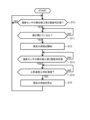
- FIG. 3 is a flowchart that is executed regardless of which of normal humidification control and rapid humidification control is selected.
- FIG. 4 is a flowchart that is executed in parallel with the flowchart shown in FIG. 3 when rapid humidification control is selected.
- the control device 40 executes only the flowchart of FIG.
- the control device 40 executes the flowchart of FIG. 3 will be described below.
- the heat generated by the bottom heater 32 evaporates the water stored in the humidifying tray D, thereby humidifying the culture chamber 20 so that the humidity of the culture chamber 20 reaches the target value. .
- the control device 40 determines in S1 whether or not there is an opening/closing history of the doors 13 and 14. Specifically, the control device 40 determines whether or not the doors 13 and 14 have been opened and closed between the current time and a predetermined time (for example, 20 minutes) before the current time. When the doors 13 and 14 are opened, high-humidity air leaks from the culture chamber 20, and the humidity in the culture chamber 20 is lowered. The predetermined time is sufficient for the humidity in the incubation chamber 20 to rise from a relatively low humidity (eg, 30% or less) to a relatively high humidity (eg, 85% or more) by opening the doors 13 and 14. It is defined. It should be noted that the control device 40 may determine in S1 whether or not it is within a predetermined time from when the power was turned on.
- a predetermined time for example, 20 minutes
- the control device 40 If there is no opening/closing history of the doors 13 and 14 (NO in S1), the control device 40 continues to control the bottom heater 32 with the first amount of electricity. On the other hand, if there is an opening/closing history of the doors 13 and 14 (YES in S1), the controller 40 humidifies the incubation chamber 20 by increasing the amount of electricity supplied to the bottom heater 32 in S2.
- the control device 40 sets the energization amount of the bottom heater 32 to a second energization amount that is larger than the first energization amount.
- the output of the bottom heater 32 and thus the amount of evaporation of the water stored in the humidifying tray D per unit time increases. Therefore, when the humidity in the culture room 20 becomes relatively low due to the opening of the doors 13 and 14, the culture room 20 can be humidified early.
- the incubation chamber 20 is humidified while the amount of power supplied to the bottom heater 32 remains the first amount of power.
- the amount of electricity supplied to the bottom heater 32 is not increased. Therefore, it is possible to prevent condensation from occurring due to an increase in the amount of electricity supplied to the bottom heater 32 when the humidity in the incubation chamber 20 is relatively low.
- the second energization amount is preset to a constant value that does not change according to the outside air temperature, the set temperature, and the predetermined ratio. It is defined.
- the humidity in the incubation chamber 20 can be stably and quickly humidified without being affected by the outside air temperature and the set temperature.
- the control device 40 determines whether the detected value of the indoor temperature sensor 24 is greater than the temperature determination value.
- the temperature determination value is determined in advance by actually measuring it through an experiment or the like, and is stored in the control device 40 in advance.
- the temperature determination value is, for example, set to a value lower than the set temperature by a predetermined value (for example, 0.2).
- a predetermined value for example, 0.2.
- control device 40 may determine the detection value of the humidity sensor 26 in addition to determining the detection value of the room temperature sensor 24 in S3. Specifically, it is determined whether the detected value of the room temperature sensor 24 is equal to or less than the temperature judgment value and the detection value of the humidity sensor 26 is equal to or less than the first humidity judgment value.
- the first humidity determination value is determined in advance by actually measuring it through an experiment or the like, and is stored in the control device 40 in advance. Also, the first humidity determination value is determined in consideration of the detection error of the humidity sensor 26, which is the difference between the detection value of the humidity sensor 26 and the actual humidity of the incubation chamber 20, as described below. The magnitude of the detection error of humidity sensor 26 differs for each humidity sensor used as humidity sensor 26 .
- the first humidity judgment value is set to a value smaller than the value obtained by subtracting the magnitude of the detection error of the humidity sensor 26 from the target value. Therefore, the actual humidity in the incubation chamber 20 when the detected value of the humidity sensor 26 is the first humidity judgment value becomes a value smaller than the target value.
- the first humidity judgment value is set at 80%, for example. Thereby, it is possible to prevent condensation from occurring while the control device 40 is executing S3.
- the control device 40 When the detected value of the indoor temperature sensor 24 is equal to or lower than the temperature judgment value (NO in S3), the control device 40 continues to control the bottom heater 32 with the second amount of power. On the other hand, when the temperature of the incubation chamber 20 rises and the detection value of the room temperature sensor 24 becomes greater than the temperature determination value (YES in S3), the controller 40 reduces the amount of power supplied to the bottom heater 32 in S4. Return to continue humidifying the incubation chamber 20 .
- the amount of power supplied to the bottom heater 32 stabilizes at the first amount of power supplied to the culture chamber 20 as described above.
- the actual humidity stabilizes at the reached humidity value, ie approximately the target value.
- the control device 40 executes the flowcharts of FIGS. 3 and 4 in parallel.
- the control device 40 executes the flowchart of FIG. 3 in the same manner as described above.
- the operation of the culture device 1 when the control device 40 executes the flowchart of FIG. 4 will be described below.
- the steam supply 18 is inactive.
- the control device 40 determines in S10 whether or not the detected value of the humidity sensor 26 is equal to or less than the second humidity determination value.
- the second humidity judgment value is determined in advance by actual measurement such as an experiment so as to be lower than a value obtained by subtracting the magnitude of the detection error of the humidity sensor 26 from the target value. , are pre-stored in the control device 40 .
- the second humidity judgment value is set at 80%, for example. If the detected value of humidity sensor 26 is greater than the second humidity determination value (NO in S10), control device 40 keeps steam supply device 18 in a non-operating state.
- control device 40 determines in S11 whether doors 13 and 14 are closed.
- control device 40 keeps the steam supply device 18 inactive.
- control device 40 starts supplying steam in S12. As a result, the supply of steam is started when the doors 13 and 14 are open, and it is possible to prevent the steam from leaking out of the culture chamber 20 and splashing on the user or the like.
- the control device 40 Based on the value detected by the humidity sensor 26, the control device 40 adjusts the amount of steam supplied by the steam supply device 18 per unit time through feedback control (for example, PID control).
- PID control the control device 40 controls the steam supply device 18 so that the amount of steam supplied by the steam supply device 18 per unit time is continuously reduced as the detected value of the humidity sensor 26 approaches the target value. do.
- the control device 40 may perform feedback control that changes the amount of steam stepwise according to the range of the detection value of the humidity sensor 26 .
- the amount of steam supplied by the steam supply device 18 per unit time is greater than the amount of evaporation of water stored in the humidifying tray D per unit time when the bottom heater 32 is controlled by the first power supply amount. big. As a result, the humidity in the incubation chamber 20 can be stabilized and humidified at an early stage.
- the control device 40 determines whether or not the detected value of the humidity sensor 26 is equal to or greater than the third humidity determination value.
- the third humidity determination value is determined in advance by actually measuring it through an experiment or the like, and is stored in the control device 40 in advance.
- the third humidity judgment value is determined based on the detection error of the humidity sensor 26, like the first humidity judgment value. Specifically, the third humidity determination value is set to a value smaller than the value obtained by subtracting the magnitude of the detection error of the humidity sensor 26 from the target value. Therefore, the actual humidity in the culture chamber 20 when the detected value of the humidity sensor 26 is the third humidity judgment value becomes a value smaller than the target value.
- the third humidity judgment value is preferably a value that is at least 5% lower than the target value. As a result, even if the humidity sensor 26 has a detection error, the actual humidity in the incubation chamber 20 exceeds the target value. can be prevented. Furthermore, by setting the third humidity judgment value to a value that is at least 10% smaller than the target value, in addition to the detection error of the humidity sensor 26, even if the detection of the humidity sensor 26 is delayed, The actual humidity in 20 can be prevented from exceeding the target value.
- the third humidity judgment value is set at 80%.
- the third humidity judgment value may be the same value as the above first humidity judgment value, or may be a different value.
- control device 40 When the detected value of the humidity sensor 26 is smaller than the third humidity judgment value (NO in S13), the control device 40 continues the supply of steam by the steam supply device 18. On the other hand, when the humidity in incubation room 20 rises and the detected value of humidity sensor 26 becomes equal to or higher than the third humidity determination value (YES in S13), control device 40 executes S14. By stopping the supply of steam in S12 based on the third humidity judgment value which is smaller than the target value in S13, even if the humidity sensor 26 has a detection error, the humidity in the incubation chamber 20 increases. and no condensation occurs. In other words, the culture chamber 20 can be humidified without causing dew condensation due to the detection error of the humidity sensor 26 .
- the third humidity judgment value is determined to be a value equal to or higher than the second humidity judgment value.
- control device 40 determines whether or not the rate of increase, which is the rate of increase per unit time of the detected value of the humidity sensor 26, is equal to or less than the determination rate. Control device 40 calculates the rising speed based on the detection value of humidity sensor 26 .
- the incubation chamber 20 when the incubation chamber 20 is humidified only by the steam evaporated from the humidifying tray D in the absence of steam supply from the steam supply device 18, the actual humidity in the incubation chamber 20 reaches the reached humidity value. It was found that the actual increase in the humidity in the incubation chamber 20 per unit time decreased linearly as it approached. That is, in this case, it was found that the amount of increase in the actual humidity in the incubation chamber 20 per unit time is proportional to the difference between the reached humidity value and the actual humidity in the incubation chamber 20 . The slope of this proportional relationship is defined as the humidifying tray rising speed coefficient. Furthermore, it was found that although the attained humidity value varies depending on the set temperature, the humidifying tray rising speed coefficient does not vary significantly depending on the set temperature, and the variation is about ⁇ 20%.
- the rate of increase which is the amount of increase per unit time of the detected value of the humidity sensor 26, can be calculated without being affected by the detection error of the humidity sensor 26. Then, regardless of the detection error of the humidity sensor 26, the rate of increase is equal to the amount of increase per unit time of the actual humidity in the culture chamber 20.
- FIG. when there is no change in the temperature of the water stored in the humidifying tray D, such as when the door is temporarily opened or closed, the reached humidity value is substantially equal to the target value. Therefore, when the energization amount of the bottom heater 32 is stabilized at the first energization amount, the actual humidity in the culture chamber 20 is stabilized substantially at the target value. That is, by calculating the rising speed, the difference between the actual humidity in the incubation chamber 20 and the target value can be indirectly detected without being affected by the detection error of the humidity sensor 26 .
- the actual humidity in the culture chamber 20 reaches a target value that is substantially equal to the target value at which dew condensation does not occur in the culture chamber 20. Humidity value stabilizes. Dew condensation does not occur in the culture chamber 20 when the atmosphere in the culture chamber 20 is stable and suitable for culture.
- control device 40 controls the supply of steam by the steam supply device 18 so that the actual humidity in the incubation chamber 20 becomes equal to the target value based on the rising speed, thereby preventing dew condensation due to the influence of the detection error of the humidity sensor 26.
- Humidification of the culture chamber 20 can be performed without generating
- the determination speed in S14 is determined in advance based on the supply of steam by the steam supply device 18, the above-mentioned attained humidity value and the humidifying tray rising speed coefficient actually measured by experiment or the like, without considering the detection error of the humidity sensor 26. and stored in the control device 40 in advance. Specifically, the actual humidity in the culture chamber 20 when the rising speed is the judgment speed is higher than the actual humidity in the culture chamber 20 when the detection value of the humidity sensor 26 is the third humidity judgment value, and , the determination speed is determined so that the humidity is lower than the target value.
- the determination speed is set to a value corresponding to a value (for example, 85%) that is 10% lower than the target value (95%) at which the actual humidity of the culture room 20 is approximately equal to the reached humidity value.
- the actual humidity in the incubation chamber 20 is 10% lower than the target value
- the actual humidity in the incubation chamber 20 due to evaporation of the water stored in the humidifying dish D is determined from the attained humidity value and the humidifying dish rising speed coefficient. It was found through experiments and the like that the amount of increase per unit time is 1%/minute. Further, in this case, feedback control is performed so that the amount of steam supplied by the steam supply device 18 is 2%/min.
- the determination speed is determined by the amount of increase per unit time (1%/min) of the actual humidity in the incubation chamber 20 due to the evaporation of the water stored in the humidifying tray D, and the amount of steam supplied by the steam supply device 18. (2%/min) is defined as 3%/min.
- the humidity in the culture room 20 can be quickly increased without causing condensation. can.
- the determination speed By setting the determination speed to a value corresponding to a value (for example, 90%) lower than the target value by 5% or more, even if the detection of the humidity sensor 26 is delayed, the actual humidity in the incubation chamber 20 can be prevented from exceeding the target value.
- control device 40 continues supply of steam by steam supply device 18 .
- the control device 40 controls the steam supply device 18 differently from S12. Specifically, the amount of steam supplied by the steam supply device 18 per unit time is adjusted by feedback control based on the rate of rise instead of the detected value of the humidity sensor 26 . In controlling the amount of steam, the amount of steam may be changed stepwise according to the range of the rising speed, or may be changed continuously according to the rising speed like PID control. In PID control, the control device 40 controls the steam supply device 18 so that the amount of steam supplied by the steam supply device 18 per unit time decreases as the rising speed approaches zero.
- the steam supply device 18 may be controlled so that the amount of steam supplied by the steam supply device 18 is 4% RH/min, that is, 2/3 times.
- the amount of steam supplied by the steam supply device 18 and the amount of increase per unit time in the actual humidity of the incubation chamber 20 due to the evaporation of the water stored in the humidifying tray D can be calculated. can be kept constant, and humidification can be stably performed up to the reached humidity value.
- the amount of steam supplied by the steam supply device 18 and the amount of increase per unit time of the actual humidity in the incubation chamber 20 due to the evaporation of the water stored in the humidifying tray D The ratio can be kept below 3:1. As a result, even if there is some error in the amount of steam supplied by the steam supply device 18, the humidity in the culture chamber 20 can be quickly increased without causing dew condensation.
- the control device 40 stops the supply of steam in S15. Specifically, the control device 40 stops the operation of the steam supply device 18 .
- the control device 40 operates the bottom heater 32 to humidify the incubation chamber 20.
- the control device 40 does not operate the steam supply device 18, and operates the bottom heater 32.
- the incubation chamber 20 is humidified by allowing the When the atmosphere in the culture chamber 20 becomes suitable for culture, the actual humidity in the culture chamber 20 is maintained at the reached humidity value, that is, approximately at the target value.
- the bottom heater 32 may be controlled by the control device 40 so as to change the temperature of the water stored in the humidifying tray D according to the target value.
- the steam supply device 18 supplies steam, so that the culture chamber 20 is humidified earlier than in the normal humidification control. be. Further, when the rising speed becomes equal to or less than the judgment speed after the detected value of the humidity sensor 26 becomes equal to or higher than the third humidity judgment value, the control device 40 does not operate the steam supply device 18, and operates the bottom heater 32 to cultivate the Humidify the chamber 20 . As a result, it is possible to prevent the humidity in the incubation chamber 20 from overshooting. Therefore, it is possible to prevent condensation from occurring in the culture chamber 20 due to the humidity in the culture chamber 20 overshooting and becoming relatively high.
- control device 40 controls the steam supply device 18 so that the amount of steam supplied by the steam supply device 18 per unit time decreases as the detected value of the humidity sensor 26 approaches the target value. Therefore, it is possible to reliably prevent dew condensation from occurring in the culture chamber 20 due to the humidity in the culture chamber 20 overshooting and becoming relatively high.
- the actual humidity in the incubation chamber 20 corresponding to the determination speed is closer to the attained humidity value (target value) than the actual humidity in the incubation chamber 20 corresponding to the third humidity determination value, the actual humidity in the incubation chamber 20 Steam can be supplied by the steam supply device 18 until the difference between the humidity and the desired value becomes relatively small. Therefore, the humidity in the culture room 20 can be raised early.
- the third humidity judgment value is set at 80%. As a result, even if the water stored in the humidifying tray D is exhausted, the rapid humidification control is executed due to the decrease in the humidity in the culture chamber 20. Therefore, the humidity in the culture chamber 20 is quickly increased to perform the third humidity determination. value can be kept.
- the control device 40 determines whether or not the detected value of the humidity sensor 26 is equal to or less than the second humidity determination value and whether or not the rising speed is equal to or greater than the second determination speed.
- the second determination speed is determined so as to be between the actual humidity in the incubation chamber 20 when the detected value is the third humidity determination value.
- the water stored in the humidifying tray D is cold water, condensation may occur on the humidifying tray D even if the humidity in the culture chamber 20 is not so high (for example, about 50%). be.
- the present inventors have found that when the culture chamber 20 is humidified only by the steam evaporated from the humidifying dish D in the absence of steam supply from the steam supply device 18, and when cold water is stored in the humidifying dish D, the culture chamber Before the humidity of 20 rises to the first reaching humidity value corresponding to the reaching humidity value approximately equal to the target value, it stabilizes once at the second reaching humidity value lower than the first reaching humidity value, and the humidifying dish D It has been found that when the water stored in is warmed up, it rises from the second ultimate humidity value to the first ultimate humidity value and finally stabilizes at the first ultimate humidity value.
- the present inventors found that when the rapid humidification control is selected, the humidity in the incubation chamber 20 rises from the second reaching humidity value to the first reaching humidity value, and then finally reaches the first reaching humidity value. It was found that dew condensation occurs on the outside of the humidifying tray D when steam is supplied by the steam supply device 18 until the humidity value is stabilized. That is, when the rapid humidification control is selected, by supplying steam from the steam supply device 18 so that the humidity in the incubation chamber 20 does not exceed the second target humidity value, It has been found that the occurrence of dew condensation can be suppressed.
- the second ultimate humidity value depends on the temperature of the cold water stored in the humidifying tray D by the user, the second ultimate humidity value is grasped without measuring the temperature of the water stored in the humidifying tray D. was difficult. Therefore, the present inventors found that when the incubation chamber 20 is humidified only by the steam evaporated from the humidifying dish D in the absence of steam supply from the steam supply device 18 as described above, the actual humidity of the incubation chamber 20 reaches Utilizing the fact that the amount of increase per unit time of the actual humidity in the incubation chamber 20 decreases linearly as it approaches the humidity value, the humidity in the incubation chamber 20 can be determined without grasping the second humidity value reached. , steam is supplied by the steam supply device 18 so as not to exceed the second ultimate humidity value.
- the third humidity judgment value is set to a value (for example, 40%) much lower than the first and second attainment humidity values, and the judgment speed is set to the vapor supply device 18 in the same manner as described above.
- 3% / min which is the judgment speed when the supply amount of , until the humidity in the incubation chamber 20 reaches from the third humidity judgment value to the second reached humidity value, the control device 40 makes the judgment in S14. That is, the difference between the actual humidity in the incubation chamber 20 and the second reached humidity value is accurately calculated by the rate of increase regardless of the detection error of the humidity sensor 26, so that the actual humidity in the incubation chamber 20 can be increased.
- the incubation chamber 20 can be humidified without exceeding the second ultimate humidity value. That is, even when cold water is stored in the humidifying tray D, the humidity in the culture chamber 20 can be increased without causing dew condensation in the culture chamber 20 .
- the water droplets adhere to the outside of the humidifying tray D when the humidity in the culture chamber 20 exceeds the second ultimate humidity due to the supply of steam by the steam supply device 18. Less often, the water droplets may evaporate before the humidity in incubation chamber 20 finally stabilizes at the first reached humidity value. That is, no condensation occurs on the outside of the humidifying tray D during the culture operation. Further, by setting the third humidity determination value relatively high as described above, the humidity in the culture chamber 20 can be kept relatively high even if the water stored in the humidifying tray D is exhausted. Further, in the present embodiment, the third humidity judgment value is set at 80%.
- the humidity sensor 26 Even if a detection error occurs, the humidity in the culture room 20 can be increased without causing dew condensation in the culture room 20 .
- FIG. 5 is another example of a flowchart executed in the rapid humidification control of the culture apparatus 1.
- the configuration of the culture apparatus 1 according to the second embodiment is the same as that of the culture apparatus 1 according to the above-described first embodiment, but part of the rapid humidification control according to the second embodiment is replaced with the rapid humidification control according to the first embodiment. It differs from humidification control.
- the flowchart shown in FIG. 5 is substantially the same as the flowchart shown in FIG. 4, but S14 in the flowchart shown in FIG. 4 is not performed, and the process proceeds from S13 to S15. Therefore, here, explanations overlapping with the explanation of the flowchart shown in FIG. 4 are omitted.
- S10 to S12 in the flowchart shown in FIG. 5 are the same as S10 to S13 in the flowchart shown in FIG.
- control device 40 executes S15. Also here, by stopping the supply of steam in S12 based on the third humidity judgment value which is smaller than the target value in S13, even if the humidity sensor 26 has a detection error, the humidity in the incubation chamber 20 is is not too high and condensation does not occur. In other words, the culture chamber 20 can be humidified without causing dew condensation due to the detection error of the humidity sensor 26 .
- the control device 40 stops the supply of steam by the steam supply device 18 in S15. That is, when the detected value of the humidity sensor 26 becomes equal to or higher than the third humidity determination value, the control device 40 does not operate the steam supply device 18 and operates the bottom heater 32 to humidify the incubation chamber 20 .
- the control device 40 After stopping the supply of steam by the steam supply device 18, the control device 40 activates the bottom heater 32 to heat the incubation chamber 20 based on the flowchart of FIG. 3, which is executed in parallel with the flowchart of FIG. Humidify. In other words, the controller 40 humidifies the incubation chamber 20 by activating the bottom heater 32 without activating the steam supply device 18 .
- the controller 40 humidifies the incubation chamber 20 by activating the bottom heater 32 without activating the steam supply device 18 .
- the bottom heater 32 may be controlled by the control device 40 so as to change the temperature of the water stored in the humidifying tray D according to the target value.
- the steam supply device 18 supplies steam, so that the culture chamber 20 is humidified earlier than in the normal humidification control. be. Further, after the detected value of the humidity sensor 26 becomes equal to or higher than the third humidity judgment value, the control device 40 does not operate the steam supply device 18 and humidifies the incubation chamber 20 by operating the bottom heater 32 . As a result, it is possible to prevent the humidity in the incubation chamber 20 from overshooting. Therefore, it is possible to prevent condensation from occurring in the culture chamber 20 due to the humidity in the culture chamber 20 overshooting and becoming relatively high.
- the culture device 1 according to the third embodiment further includes an input unit 51 into which target values are input.
- the input unit 51 is, for example, a touch panel provided in the operation unit 50 .
- control device 40 selects one of the first humidification mode and the second humidification mode to humidify the incubation chamber 20 .
- the first humidification mode is a mode in which the control device 40 humidifies the incubation chamber 20 using the steam supply section 60 and the steam supply device 18 described above.
- the second humidification mode is a mode in which the controller 40 humidifies the incubation chamber 20 using the steam supply device 18 without using the steam supply unit 60 described above. Specifically, in the second humidification mode, the control device 40 does not operate the bottom heater 32 but operates the steam supply device 18, so that the detected value of the humidity sensor 26 is equal to the target value input to the input unit 51. In this mode, the incubation chamber 20 is humidified so that the The target value in the second humidification mode is the value input by the user through the input unit 51, and is the humidity of the incubation chamber 20 desired by the user.
- the culture chamber 20 is humidified only by the steam supplied by the steam supply device 18 .
- the humidifying dish D installed in the incubation chamber 20 may be removed from the incubation chamber 20 .
- Selection of the first humidification mode or the second humidification mode is performed according to the target value, for example.
- the target humidity is 80 to 90%
- the second humidification mode is selected and only the steam supply device 18 is used to humidify the incubation chamber 20 .
- the target humidity is 90% or higher
- the first humidification mode is selected and the incubation chamber 20 is humidified using the steam supply unit 60 and the steam supply device 18 .
- the humidification control described in the first embodiment is performed.
- the control device 40 When switching from the first humidification mode to the second humidification mode, the control device 40 displays a message indicating that the liquid stored in the humidifying dish D is to be discarded or that the humidifying dish D is removed from the incubation chamber 20. The operation may be performed on the display section of the operation section 50 . Further, when switching from the second humidification mode to the first humidification mode, the control device 40 operates displays such as the fact that the humidifying dish D is to store the liquid, the humidifying dish D to be installed in the culture chamber 20, and the like. You may make it perform to the display part of the part 50. FIG.
- FIG. 6 is a flowchart executed when the second humidification mode is selected. The operation of the culture device 1 when the control device 40 executes the flowchart of FIG. 6 will be described below. At the start of the flow chart of FIG. 6, the steam supply 18 is inactive.
- control device 40 determines whether the doors 13 and 14 are closed. If doors 13 and 14 are open (NO in S20), control device 40 keeps steam supply device 18 in a non-operating state. On the other hand, if doors 13 and 14 are closed (YES at S20), controller 40 activates steam supply device 18 to start supplying steam at S21. As a result, the supply of steam is started when the doors 13 and 14 are open, and it is possible to prevent the steam from leaking out of the culture chamber 20 and splashing on the user or the like.
- the control device 40 starts supplying steam at a predetermined first supply amount.
- the first supply amount is the amount of steam supplied per unit time for quickly increasing the humidity in the incubation chamber 20 .
- the first supply amount is, for example, the amount of water stored in the humidifying tray D that evaporates per unit time when water is stored in the humidifying tray D and the bottom heater 32 is controlled by the second energization amount. It is determined to be larger than the quantity.
- the control device 40 determines whether or not the detected value of the humidity sensor 26 has reached or exceeded the fourth humidity determination value.
- the fourth humidity determination value is determined in advance so as to prevent the humidity in the culture chamber 20 from overshooting and becoming relatively high when the supply amount of steam is the first supply amount, and is stored in the control device 40. It is When the target value in the second humidification mode is 95%, the fourth humidity determination value is, for example, 95% of the target value, that is, a value corresponding to 90.2%.
- the control device 40 When the detected value of the humidity sensor 26 is smaller than the fourth humidity judgment value (NO in S22), the control device 40 continues to supply steam at the first supply amount. On the other hand, when the humidity in the incubation chamber 20 rises and the detected value of the humidity sensor 26 becomes equal to or higher than the fourth humidity judgment value (YES in S22), the controller 40 reduces the supply amount of steam in S23. Reduce.
- control device 40 supplies steam at a second supply amount that is smaller than the first supply amount.
- the second supply amount is a supply amount of steam per unit time for quickly increasing the humidity in the culture chamber 20 and preventing the humidity in the culture chamber 20 from overshooting and becoming relatively high.
- the control device 40 determines whether or not the detected value of the humidity sensor 26 has become equal to or greater than the fifth humidity determination value.
- the fifth humidity judgment value is larger than the fourth humidity judgment value, and is preset to suppress the humidity in the culture chamber 20 from overshooting and becoming relatively high when the supply amount of steam is the second supply amount. defined and stored in the controller 40 .
- the fifth humidity determination value is, for example, 99.5% of the target value, that is, a value corresponding to 94.5%.
- the control device 40 When the detected value of the humidity sensor 26 is smaller than the fifth humidity determination value (NO in S24), the control device 40 continues to supply steam at the second supply amount. On the other hand, when the humidity in the incubation chamber 20 rises and the detected value of the humidity sensor 26 becomes equal to or higher than the fifth humidity judgment value (YES in S24), the controller 40 reduces the supply amount of steam in S25. Reduce.
- control device 40 supplies steam at a third supply amount that is smaller than the second supply amount.
- the third supply amount is the supply amount of steam per unit time for reliably suppressing the overshoot of the humidity in the incubation chamber 20 to a relatively high level.
- the control device 40 determines whether or not the detected value of the humidity sensor 26 has reached or exceeded the sixth humidity determination value.
- the sixth humidity judgment value is larger than the fifth humidity judgment value, and is designed to reliably suppress the humidity in the culture chamber 20 from overshooting and becoming relatively high when the supply amount of steam is the third supply amount. pre-determined to It is stored in the control device 40 .
- the sixth humidity determination value is, for example, 99.95% of the target value, that is, a value corresponding to 94.9%.
- the control device 40 When the detected value of the humidity sensor 26 is smaller than the sixth humidity judgment value (NO in S26), the control device 40 continues to supply steam at the third supply amount. On the other hand, when the humidity in the incubation chamber 20 rises and the detected value of the humidity sensor 26 becomes equal to or higher than the sixth humidity judgment value (YES in S26), the controller 40 reduces the supply amount of steam in S27. Stop. At this time, the detected value of the humidity sensor 26 is almost equal to the target value.
- control device 40 operates the steam supply device 18 so that the steam supply amount is reduced step by step as the humidity in the incubation chamber 20 approaches the target value. Therefore, it is possible to set the humidity of the culture room 20 to the target value input from the input unit 51 while suppressing the overshoot of the humidity of the culture room 20 .
- control device 40 may adjust the supply amount of steam by executing PID control instead of the flowchart of FIG.
- control device 40 may prevent condensation from occurring in the dehumidifying member 19 in the second humidification mode. In this case, the control device 40 does not operate the cooling device 19a. As a result, the humidity of the culture apparatus 1 can be accurately adjusted to the user's desired target value.
- the present disclosure is suitably used as a culture device.
Landscapes
- Chemical & Material Sciences (AREA)
- Engineering & Computer Science (AREA)
- Organic Chemistry (AREA)
- Zoology (AREA)
- Health & Medical Sciences (AREA)
- Life Sciences & Earth Sciences (AREA)
- Bioinformatics & Cheminformatics (AREA)
- Wood Science & Technology (AREA)
- Sustainable Development (AREA)
- Microbiology (AREA)
- Biotechnology (AREA)
- Biomedical Technology (AREA)
- Biochemistry (AREA)
- General Engineering & Computer Science (AREA)
- General Health & Medical Sciences (AREA)
- Genetics & Genomics (AREA)
- Analytical Chemistry (AREA)
- Physics & Mathematics (AREA)
- Thermal Sciences (AREA)
- Computer Hardware Design (AREA)
- Apparatus Associated With Microorganisms And Enzymes (AREA)
Priority Applications (4)
| Application Number | Priority Date | Filing Date | Title |
|---|---|---|---|
| EP23746905.1A EP4450610A4 (en) | 2022-01-26 | 2023-01-23 | CULTURAL DEVICE |
| CN202380017837.4A CN118574920A (zh) | 2022-01-26 | 2023-01-23 | 培养装置 |
| JP2023576903A JP7724314B2 (ja) | 2022-01-26 | 2023-01-23 | 培養装置 |
| US18/779,974 US20240376420A1 (en) | 2022-01-26 | 2024-07-22 | Culture device |
Applications Claiming Priority (2)
| Application Number | Priority Date | Filing Date | Title |
|---|---|---|---|
| JP2022010203 | 2022-01-26 | ||
| JP2022-010203 | 2022-01-26 |
Related Child Applications (1)
| Application Number | Title | Priority Date | Filing Date |
|---|---|---|---|
| US18/779,974 Continuation US20240376420A1 (en) | 2022-01-26 | 2024-07-22 | Culture device |
Publications (1)
| Publication Number | Publication Date |
|---|---|
| WO2023145694A1 true WO2023145694A1 (ja) | 2023-08-03 |
Family
ID=87472009
Family Applications (1)
| Application Number | Title | Priority Date | Filing Date |
|---|---|---|---|
| PCT/JP2023/001960 Ceased WO2023145694A1 (ja) | 2022-01-26 | 2023-01-23 | 培養装置 |
Country Status (5)
| Country | Link |
|---|---|
| US (1) | US20240376420A1 (https=) |
| EP (1) | EP4450610A4 (https=) |
| JP (1) | JP7724314B2 (https=) |
| CN (1) | CN118574920A (https=) |
| WO (1) | WO2023145694A1 (https=) |
Cited By (1)
| Publication number | Priority date | Publication date | Assignee | Title |
|---|---|---|---|---|
| WO2024241953A1 (ja) * | 2023-05-24 | 2024-11-28 | Phcホールディングス株式会社 | 培養装置及び湿度センサの校正方法 |
Citations (7)
| Publication number | Priority date | Publication date | Assignee | Title |
|---|---|---|---|---|
| JP2013066435A (ja) * | 2011-09-22 | 2013-04-18 | Panasonic Healthcare Co Ltd | ヒートパイプを備えた培養装置 |
| JP2013523086A (ja) * | 2010-03-25 | 2013-06-17 | フラウンホーファー−ゲゼルシャフト ツル フェルデルング デル アンゲヴァンテン フォルシュング エー ファウ | インキュベータ装置、およびそれを動作させる方法 |
| JP5727187B2 (ja) | 2010-09-30 | 2015-06-03 | パナソニックヘルスケアホールディングス株式会社 | インキュベータ |
| WO2015136794A1 (ja) * | 2014-03-10 | 2015-09-17 | 株式会社Screenホールディングス | 撮像装置、撮像システムおよびインキュベーター |
| CN106591125A (zh) * | 2016-12-31 | 2017-04-26 | 宁波华仪宁创智能科技有限公司 | 新型细胞培养箱的加湿装置及方法 |
| CN212560302U (zh) * | 2020-07-20 | 2021-02-19 | 苏州安泰空气技术有限公司 | 一种带有分流装置的防凝露培养箱结构 |
| JP2022010203A (ja) | 2017-05-08 | 2022-01-14 | 株式会社コナミデジタルエンタテインメント | ゲーム装置、及び、ゲーム装置のプログラム |
Family Cites Families (4)
| Publication number | Priority date | Publication date | Assignee | Title |
|---|---|---|---|---|
| DE2924446C2 (de) * | 1979-06-18 | 1982-09-16 | W.C. Heraeus Gmbh, 6450 Hanau | Verfahren und Vorrichtung zum Kultivieren von Zellen und Geweben von Menschen und Tieren oder von Mikroorganismen |
| DE102011111754A1 (de) * | 2011-08-24 | 2013-02-28 | Thermo Electron Led Gmbh | Brutschrank mit verbesserter Innenraum-Befeuchtung |
| JP5887023B2 (ja) * | 2013-03-22 | 2016-03-16 | パナソニックヘルスケアホールディングス株式会社 | 培養装置 |
| CN211947072U (zh) | 2019-12-30 | 2020-11-17 | 深圳富佑细胞生物技术股份有限公司 | 植物细胞培养罐系统 |
-
2023
- 2023-01-23 EP EP23746905.1A patent/EP4450610A4/en active Pending
- 2023-01-23 CN CN202380017837.4A patent/CN118574920A/zh active Pending
- 2023-01-23 WO PCT/JP2023/001960 patent/WO2023145694A1/ja not_active Ceased
- 2023-01-23 JP JP2023576903A patent/JP7724314B2/ja active Active
-
2024
- 2024-07-22 US US18/779,974 patent/US20240376420A1/en active Pending
Patent Citations (7)
| Publication number | Priority date | Publication date | Assignee | Title |
|---|---|---|---|---|
| JP2013523086A (ja) * | 2010-03-25 | 2013-06-17 | フラウンホーファー−ゲゼルシャフト ツル フェルデルング デル アンゲヴァンテン フォルシュング エー ファウ | インキュベータ装置、およびそれを動作させる方法 |
| JP5727187B2 (ja) | 2010-09-30 | 2015-06-03 | パナソニックヘルスケアホールディングス株式会社 | インキュベータ |
| JP2013066435A (ja) * | 2011-09-22 | 2013-04-18 | Panasonic Healthcare Co Ltd | ヒートパイプを備えた培養装置 |
| WO2015136794A1 (ja) * | 2014-03-10 | 2015-09-17 | 株式会社Screenホールディングス | 撮像装置、撮像システムおよびインキュベーター |
| CN106591125A (zh) * | 2016-12-31 | 2017-04-26 | 宁波华仪宁创智能科技有限公司 | 新型细胞培养箱的加湿装置及方法 |
| JP2022010203A (ja) | 2017-05-08 | 2022-01-14 | 株式会社コナミデジタルエンタテインメント | ゲーム装置、及び、ゲーム装置のプログラム |
| CN212560302U (zh) * | 2020-07-20 | 2021-02-19 | 苏州安泰空气技术有限公司 | 一种带有分流装置的防凝露培养箱结构 |
Non-Patent Citations (1)
| Title |
|---|
| See also references of EP4450610A4 |
Cited By (1)
| Publication number | Priority date | Publication date | Assignee | Title |
|---|---|---|---|---|
| WO2024241953A1 (ja) * | 2023-05-24 | 2024-11-28 | Phcホールディングス株式会社 | 培養装置及び湿度センサの校正方法 |
Also Published As
| Publication number | Publication date |
|---|---|
| EP4450610A4 (en) | 2025-04-16 |
| JP7724314B2 (ja) | 2025-08-15 |
| US20240376420A1 (en) | 2024-11-14 |
| EP4450610A1 (en) | 2024-10-23 |
| JPWO2023145694A1 (https=) | 2023-08-03 |
| CN118574920A (zh) | 2024-08-30 |
Similar Documents
| Publication | Publication Date | Title |
|---|---|---|
| JP3197696B2 (ja) | 培養装置 | |
| JP5570191B2 (ja) | インキュベータ | |
| US8227239B2 (en) | Culture apparatus | |
| RU2711938C2 (ru) | Способ эксплуатации увлажнительного модуля, увлажнительный модуль и климатический шкаф, имеющий увлажнительный модуль | |
| WO2018212029A1 (ja) | インキュベータ | |
| JP6713344B2 (ja) | インキュベータ | |
| JP2011521705A5 (https=) | ||
| JP7724314B2 (ja) | 培養装置 | |
| JP7269258B2 (ja) | 培養装置 | |
| JP6181927B2 (ja) | 蒸気式加湿器及びその排水制御方法 | |
| KR20130068035A (ko) | 가습량조절방법 및 이를 이용한 가습장치 | |
| JP2001116303A (ja) | 加湿装置 | |
| KR101867758B1 (ko) | 연료전지 스택의 퍼지 제어 장치 및 방법 | |
| JPWO2023145694A5 (https=) | ||
| JP2020092715A (ja) | インキュベータ | |
| WO2024241953A1 (ja) | 培養装置及び湿度センサの校正方法 | |
| JP7793034B2 (ja) | 培養装置 | |
| JP4036563B2 (ja) | 恒温・恒湿空気供給装置 | |
| JP7557884B2 (ja) | 蒸気加湿装置 | |
| JP2008215635A (ja) | 加湿器、加湿器給水方法および空気調和機 | |
| JP6901747B2 (ja) | 加湿槽付き空調機 | |
| WO2023068061A1 (ja) | 培養装置 | |
| KR101801831B1 (ko) | 박막 증착 장치 및 방법 | |
| CN119088107A (zh) | 湿度发生装置 | |
| JP2001314148A (ja) | 冷凍パン生地用自動発酵庫 |
Legal Events
| Date | Code | Title | Description |
|---|---|---|---|
| 121 | Ep: the epo has been informed by wipo that ep was designated in this application |
Ref document number: 23746905 Country of ref document: EP Kind code of ref document: A1 |
|
| ENP | Entry into the national phase |
Ref document number: 2023576903 Country of ref document: JP Kind code of ref document: A |
|
| WWE | Wipo information: entry into national phase |
Ref document number: 202380017837.4 Country of ref document: CN |
|
| ENP | Entry into the national phase |
Ref document number: 2023746905 Country of ref document: EP Effective date: 20240718 |
|
| NENP | Non-entry into the national phase |
Ref country code: DE |