WO2023145083A1 - 動作モードを選択する機能を有するツールを切り換える装置、教示装置、制御装置、ロボットシステム、及び方法 - Google Patents
動作モードを選択する機能を有するツールを切り換える装置、教示装置、制御装置、ロボットシステム、及び方法 Download PDFInfo
- Publication number
- WO2023145083A1 WO2023145083A1 PCT/JP2022/003626 JP2022003626W WO2023145083A1 WO 2023145083 A1 WO2023145083 A1 WO 2023145083A1 JP 2022003626 W JP2022003626 W JP 2022003626W WO 2023145083 A1 WO2023145083 A1 WO 2023145083A1
- Authority
- WO
- WIPO (PCT)
- Prior art keywords
- robot
- tool
- mode
- teaching
- function
- Prior art date
- Legal status (The legal status is an assumption and is not a legal conclusion. Google has not performed a legal analysis and makes no representation as to the accuracy of the status listed.)
- Ceased
Links
Images


Classifications
-
- G—PHYSICS
- G05—CONTROLLING; REGULATING
- G05B—CONTROL OR REGULATING SYSTEMS IN GENERAL; FUNCTIONAL ELEMENTS OF SUCH SYSTEMS; MONITORING OR TESTING ARRANGEMENTS FOR SUCH SYSTEMS OR ELEMENTS
- G05B19/00—Programme-control systems
- G05B19/02—Programme-control systems electric
- G05B19/42—Recording and playback systems, i.e. in which the programme is recorded from a cycle of operations, e.g. the cycle of operations being manually controlled, after which this record is played back on the same machine
- G05B19/425—Teaching successive positions by numerical control, i.e. commands being entered to control the positioning servo of the tool head or end effector
-
- B—PERFORMING OPERATIONS; TRANSPORTING
- B25—HAND TOOLS; PORTABLE POWER-DRIVEN TOOLS; MANIPULATORS
- B25J—MANIPULATORS; CHAMBERS PROVIDED WITH MANIPULATION DEVICES
- B25J9/00—Programme-controlled manipulators
- B25J9/16—Programme controls
- B25J9/1656—Programme controls characterised by programming, planning systems for manipulators
Definitions
- the present disclosure relates to a device, a teaching device, a control device, a robot system, and a method for switching tools having a function of selecting an operation mode.
- Patent Document 1 A tool that has a function of switching the operation mode of a robot is known (for example, Patent Document 1).
- a device for switching tools having a function of selecting an operation mode of a robot includes a tool switching unit that switches a tool whose function is to be enabled from a first tool to a second tool.
- a method for switching a tool having a function of selecting an operation mode of a robot is performed by a processor switching the tool for which the function is enabled from a first tool to a second tool.
- the operator can easily switch tools that enable the function of selecting the operation mode without adding software or changing settings.
- the work involved in constructing or modifying the robot system can be simplified.
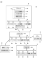
- FIG. 1 is a schematic diagram of a robot system according to one embodiment
- FIG. 2 is a block diagram of the robot system shown in FIG. 1
- FIG. 2 is a schematic diagram of the mode switching device shown in FIG. 1
- FIG. An example of the mode selection image data for selecting driving mode is shown.
- An example of image data for inputting tool switching is shown.
- 2 is a block diagram showing another function of the robot system shown in FIG. 1;
- FIG. Another example of image data for inputting tool switching is shown.
- It is a schematic diagram of a robot system according to another embodiment.
- FIG. 1 The robot system 10 includes a robot 12 , a control device 14 , a teaching device 16 , a host controller 18 and a mode switching device 20 .
- the robot 12 is a vertical multi-joint robot and has a robot base 22 , a swing trunk 24 , a lower arm section 26 , an upper arm section 28 , a wrist section 30 and an end effector 32 .
- the robot base 22 is fixed on the floor of the work cell or on an automated guided vehicle (AGV).
- the swing barrel 24 is provided on the robot base 22 so as to be rotatable about a vertical axis.
- the lower arm 26 is provided on the swing barrel 24 so as to be rotatable about the horizontal axis, and the upper arm 28 is rotatably provided at the tip of the lower arm 26 .
- the wrist portion 30 is provided at the distal end portion of the upper arm portion 28 so as to be rotatable about two axes perpendicular to each other.
- the end effector 32 is detachably attached to the tip of the wrist 30 (so-called wrist flange).
- the end effector 32 is a robot hand, a welding torch, a laser processing head, or the like, and performs predetermined work (work handling, welding, laser processing, etc.) on the work.
- a plurality of servo motors 34 are provided in the robot base 22, the swing body 24, the lower arm section 26, the upper arm section 28, and the wrist section 30, respectively.
- the servomotor 34 rotates each movable component of the robot 12 (that is, the swing body 24, the lower arm 26, the upper arm 28, and the wrist 30) around the drive shaft in response to commands from the control device 14. Let In this way, the robot 12 operates according to commands from the control device 14 to move the end effector 32 to an arbitrary target position.
- controller 14 controls the motion of the robot 12 .
- controller 14 is a computer having processor 40 , memory 42 , I/O interface 44 , input device 46 , and display device 48 .
- the processor 40 has a CPU, GPU, or the like, is communicatively connected to a memory 42, an I/O interface 44, an input device 46, and a display device 48 via a bus 50, and controls the robot while communicating with these components. Arithmetic processing is performed to realize functions.
- the memory 42 has RAM, ROM, etc., and temporarily or permanently stores various data.
- the I/O interface 44 has, for example, an Ethernet (registered trademark) port, a USB port, an optical fiber connector, or an HDMI (registered trademark) terminal, and exchanges data with external devices under instructions from the processor 40. Communicate by wire or wirelessly.
- the input device 46 has push buttons, a keyboard, a mouse, a touch panel, or the like, and receives input data from the operator.
- the display device 48 has a liquid crystal display, an organic EL display, or the like, and visually displays various data under commands from the processor 40 .
- the input device 46 and the display device 48 may be integrated into the housing of the control device 14, or may be externally attached to the housing of the control device 14 as separate bodies. .
- the teaching device 16 teaches the robot 12 a predetermined motion.
- the teaching device 16 is, for example, a portable computer such as a teaching pendant or tablet terminal device, and has a processor 60, a memory 62, an I/O interface 64, an input device 66, and a display device 68.
- the configurations of the processor 60, memory 62, I/O interface 64, input device 66, and display device 68 are the same as those of the processor 40, memory 42, I/O interface 44, input device 46, and display device 48 described above. Therefore, redundant description is omitted.
- the input device 66 and the display device 68 are integrated in the housing 16a of the teaching device 16, as shown in FIG.
- the input device 66 includes an emergency stop button 66a.
- the emergency stop button 66a is for stopping the robot 12 in an emergency.
- the processor 60 is communicatively connected to a memory 62, an I/O interface 64, an input device 66, and a display device 68 via a bus 70, and communicates with these components to perform arithmetic processing for realizing teaching functions. conduct.
- the processor 60 of the teaching device 16 sends teaching commands CMt to the servo motors 34 of the robot 12 via the control device 14 according to input data to the input device 66, and jogs the robot 12 according to the teaching commands CMt. It is configured so that it can be The operator operates the input device 66 to teach the robot 12 a predetermined motion, and the processor 60 generates a motion program PG that causes the robot 12 to perform the taught predetermined motion.
- the host controller 18 gives commands to the control device 14 to control the control device 14 .
- the host controller 18 is, for example, a programmable logic controller (PLC) or a computer such as a desktop PC, and includes a processor 80, a memory 82, an I/O interface 84, an input device 86, and a display device 88.
- PLC programmable logic controller
- the configurations of the processor 80, memory 82, I/O interface 84, input device 86, and display device 88 are the same as those of the processor 40, memory 42, I/O interface 44, input device 46, and display device 48 described above. Therefore, redundant description is omitted.
- Processor 80 is communicatively connected to memory 82, I/O interface 84, input device 86, and display device 88 via bus 90, and while communicating with these components, performs arithmetic processing for realizing host control functions. I do. For example, the processor 80 sends a command to the control device 14 according to a pre-determined production management scheme, and operates the robot 12 under the control of the control device 14 to perform a predetermined work.
- the mode switching device 20 has a function FC for selecting one of a plurality of operation modes OM in which the controller 14 operates the robot 12 .
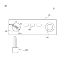
- An example of the mode switching device 20 is shown in FIG.
- Mode switching device 20 has housing 100 , physical switch 102 , emergency stop button 104 , program execution button 108 and physical key 106 .
- the housing 100 is hollow and accommodates therein electronic components (such as LSIs) that implement the functions of the mode switching device 20 .
- the physical switch 102 is for selecting one of a plurality of operation modes OM of the robot 12, and is rotatably provided on the housing 100 so as to be exposed to the outside of the housing 100. .
- the operation mode OM includes a teaching mode OM1, an operation confirmation mode OM2, and an automatic operation mode OM3.
- the teaching mode OM1 is an operation mode OM in which the operator teaches the robot 12 a predetermined operation using the teaching device 16 to create an operation program PG for the robot 12 .
- the operator operates the input device 66 of the teaching device 16 to give a teaching command CMt to the control device 14, and the control device 14 jogs the robot 12 according to the teaching command CMt.
- an operator instructs the robot 12 to provide a plurality of teaching points TP for positioning an end effector (or TCP) when performing work on a workpiece, and a plurality of teaching points TP defined by the teaching points TP. It teaches the movement path MP of the end effector (or TCP).
- the operator teaches the robot 12 a predetermined motion for performing work on the work.
- the operator operates the robot 12 at the first speed V1 in order to teach the robot 12 a predetermined motion.
- the processor 40 of the control device 14 limits the movement speed of the robot 12 (for example, the end effector 32) to a first speed V1 or less.
- the operation confirmation mode OM2 is an operation mode OM that causes the robot 12 to try a predetermined operation taught in the teaching mode OM1 in order to confirm the predetermined operation.
- the operator causes the robot 12 to test-execute the incomplete motion program PG′ generated during the teaching in the teaching mode OM1, thereby instructing the robot 12 to perform the motion taught (that is, the motion). Appropriateness of program PG').
- the operator operates the input device 66 of the teaching device 16 to give an operation confirmation command CMv to the controller 14, and the controller 14 instructs the robot 12 according to the operation confirmation command CMv.
- the robot 12 is operated at a second speed V2 (>V1) higher than the first speed V1 according to the motion program PG' created at this time.
- the processor 40 in order to confirm the operation taught to the robot 12 (specifically, the operation of the robot 12 according to the operation program PG'), the processor 40 follows the operation confirmation command CMv to perform the operation at a higher speed. to operate the robot 12 at a second speed V2 of .
- the second speed V2 is, for example, the speed defined in the operation program PG'.
- the operator confirms the attempted motion of the robot 12 in the motion confirmation mode OM2, executes the teaching mode OM1 again, and adds or corrects the teaching point TP (or movement path MP) defined in the motion program PG'. do.
- the processor 60 generates a formal motion program PG for executing work on the workpiece, and provides the generated motion program PG to the controller 14 .
- operation program PG operation conditions such as the speed V3 of the robot 12 are defined together with the taught point TP and movement path MP.
- the processor 40 of the control device 14 is operating the robot 12 in the teaching mode OM1 and the operation confirmation mode OM2, tools other than the teaching device 16 (that is, the control device 14, the host controller 18, the mode switching device 20) It is prohibited to command the execution of the operation program PG (or PG') from the input devices (input devices 46, 66, 86).
- the automatic operation mode OM3 is, for example, an operation mode OM in which the robot 12 is automatically operated according to the operation program PG in order to cause the robot 12 to perform actual work on the workpiece within the work cell.
- the operator operates the program execution button 108 of the mode switching device 20 or the input device 86 of the host controller 18 to give the automatic operation start command CMa to the control device 14 .
- the processor 40 of the control device 14 starts the automatic operation mode OM3, and automatically operates the robot 12 according to the operation program PG at the speed V3 specified in the operation program PG. .
- This speed V3 can be equal to or higher than the above speed V2 (V3 ⁇ V2).
- transmission of the automatic operation start command CMa from the input device 66 of the teaching device 16 to the control device 14 is prohibited.
- transmission of the teaching command CMt and the operation confirmation command CMv from the input device 66 of the teaching device 16 to the control device 14 is prohibited during the automatic operation mode OM3.
- the I/O interface 44 of the control device 14 includes the servo motors 34 of the robot 12, the I/O interface 64 of the teaching device 16, the I/O interface 84 of the host controller 18, and , the mode switching device 20 (specifically, the physical switch 102, the emergency stop button 104, and the program execution button 108) so as to be able to communicate by wire or wirelessly.
- the physical switch 102 selects one of the above-described teaching mode OM1, operation confirmation mode OM2, and automatic operation mode OM3.
- "AUTO”, “T1”, and “T2” are displayed on the housing 100, and the physical switch 102 rotates with respect to the housing 100 so that these "AUTO”, “T1”, and “T2” are displayed.
- "T1" or "T2" can be selected.
- AUTO corresponds to the automatic operation mode OM3
- T1 corresponds to the teaching mode OM1
- T2 corresponds to the operation confirmation mode OM2.
- the operator selects the operation mode OM to be executed by the control device 14 from “AUTO” (automatic operation mode OM3), "T1” (teaching mode OM1), and “T2” (operation mode OM3).
- a confirmation mode OM2) can be selected. Note that FIG. 3 shows a state in which the physical switch 102 selects “AUTO” (automatic operation mode OM3).
- the mode switching device 20 transmits a teaching mode selection command CM1 to the control device 14, and changes the operation mode OM executed by the control device 14 to the teaching mode. Go to OM1.
- the operator can use the teaching device 16 to operate the robot 12 at the first speed V1 via the control device 14 in the teaching mode OM1 to teach the robot 12 the motion.
- the mode switching device 20 transmits an operation confirmation mode selection command CM2 to the control device 14, and selects the operation mode OM executed by the control device 14. to the operation check mode OM2.
- the operator uses the teaching device 16 to operate the robot 12 at the second speed V2 via the control device 14 in the operation confirmation mode OM2, and confirms the operation taught to the robot 12 (for example, operation operation confirmation of the program PG').
- the mode switching device 20 transmits an automatic operation mode selection command CM3 to the control device 14, and the operation mode OM is executed by the control device 14. to the automatic operation mode OM3.
- the operator can operate the program execution button 108 of the mode switching device 20 or the host controller 18 to automatically operate the robot 12 according to the operation program PG.
- the physical key 106 can be inserted into and removed from a keyhole 102a formed in the physical switch 102.
- the physical switch 102 can be rotated. 102 becomes operational.
- the rotation of the physical switch 102 is restricted and the physical switch 102 becomes inoperable.
- the program execution button 108 can cause the control device 14 to start the automatic operation mode OM3. Specifically, the operator operates the program execution button 108 with "AUTO" selected by the physical switch 102 . Then, the mode switching device 20 transmits the automatic operation start command CMa to the control device 14 following the automatic operation mode selection command CM3.
- the processor 40 of the control device 14 shifts the operation mode OM to the automatic operation mode OM3 in response to the automatic operation mode selection command CM3. As a result, the processor 40 becomes ready to accept the automatic operation start command CMa, but prohibits acceptance of the teaching command CMt and the operation confirmation command CMv.
- the processor 40 causes the robot 12 to automatically operate according to the operation program PG as described above.
- the emergency stop button 104 is for stopping the robot 12 in an emergency.
- the processor 40 of the control device 14 automatically operates the robot 12 in the automatic operation mode OM3 (or operates the robot 12 according to the operation program PG' in the operation confirmation mode OM2)
- the operator When emergency stop button 104 is pressed, mode switching device 20 gives control device 14 an emergency stop command CMs.
- the control device 14 In response to the emergency stop command CMs, the control device 14, for example, stops the command (current command) to each servomotor 34, or activates a brake mechanism that brakes the rotating shaft of each servomotor 34. , the robot 12 is brought to an emergency stop.
- the mode switching device 20 has a function FC for selecting the operation mode OM (that is, the teaching mode OM1, the operation confirmation mode OM2, or the automatic operation mode OM3) in which the robot 12 is operated by the control device 14.
- the teaching device 16 like the mode switching device 20, has a function FC for selecting the operation mode OM of the robot 12.
- processor 60 of teaching device 16 generates mode selection image data 200 for accepting selection of operation mode OM, and displays it on display device 68 .
- FIG. 4 shows an example of the mode selection image data 200. As shown in FIG.
- the mode selection image data 200 is a graphical user interface (GUI) that allows the operator to select the operation mode OM, and includes T1 button image data 202, T2 button image data 204, and AUTO button image data 206.
- GUI graphical user interface
- the T1 button image data 202, the T2 button image data 204, and the AUTO button image data 206 correspond to the teaching mode OM1, the operation confirmation mode OM2, and the automatic operation mode OM3, respectively.
- the operator clicks on the image of the T1 button image data 202, the T2 button image data 204, or the AUTO button image data 206 to select the teaching mode OM1 and the operation confirmation mode.
- OM2 or automatic operation mode OM3 can be selected.
- processor 60 when processor 60 receives input IPm for selecting T1 button image data 202 in mode selection image data 200 from input device 66, processor 60 transmits teaching mode selection command CM1 to control device 14, and control device 14 to the teaching mode OM1.
- the processor 60 when the processor 60 receives an input IPm for selecting the T2 button image data 204 from the input device 66, the processor 60 transmits an operation confirmation mode selection command CM2 to the control device 14, and selects the operation mode OM executed by the control device 14 as an operation mode. It shifts to confirmation mode OM2.
- the processor 60 receives the input IPm for selecting the AUTO button image data 206 from the input device 66, it transmits an automatic operation mode selection command CM3 to the control device 14, and selects the operation mode OM executed by the control device 14 as automatic.
- the operation teaching mode OM3 is entered.
- the processor 60 transmits an emergency stop command CMs to the control device 14, Make an emergency stop.
- the processor 80 of the host controller 18 generates mode selection image data 200 and displays it on the display device 88 in the same manner as the teaching device 16 .
- processor 80 receives input IPm for selecting T1 button image data 202, T2 button image data 204, or AUTO button image data 206 from input device 86, processor 80 issues teaching mode selection command CM1, operation check mode selection command CM2, or An automatic operation mode selection command CM3 is transmitted to the control device 14, and the operation mode OM executed by the control device 14 is shifted to the teaching mode OM1, the operation confirmation mode OM2, or the automatic operation teaching mode OM3.
- control device 14 also has a function FC for selecting the operation mode OM of the robot 12, like the teaching device 16.
- input device 46 of controller 14 may include physical switch 102 described above.
- the operator operates the physical switch 102 to select "AUTO” (automatic operation mode OM3), "T1" (teaching mode OM1), or "T2" (operation confirmation mode OM2).
- AUTO automatic operation mode OM3
- T1 teaching mode OM1
- T2 operation confirmation mode OM2
- the processor 40 of the control device 14 generates the mode selection image data 200 and displays it on the display device 48 in the same way as the teaching device 16 does.
- processor 40 receives input IPm for selecting T1 button image data 202, T2 button image data 204, or AUTO button image data 206 from input device 46
- processor 40 issues teaching mode selection command CM1, operation check mode selection command CM2, or
- An automatic operation mode selection command CM3 is transmitted to the control device 14, and the operation mode OM executed by the control device 14 is shifted to the teaching mode OM1, the operation confirmation mode OM2, or the automatic operation teaching mode OM3.
- the processor 40 of the control device 14 Before displaying the mode selection image data 200 on the display device 48, 68 or 88, the processor 40 of the control device 14, the processor 60 of the teaching device 16, or the processor 80 of the host controller 18 receives the function FC from the operator. An input IPd of the digital key DK for enabling use may be accepted.
- the digital key DK can be, for example, a password or operator identification information (employee number, etc.).
- the processor 40, 60 or 80 receives the input IPd through the input device 46, 66 or 86, it displays the mode selection image data 200 on the display device 48, 68 or 88 so that the operator can select the operation mode OM. do.
- the processor 40, 60 or 80 generates digital key image data (not shown) for entering the digital key DK and displays it on the display device 48, 68 or 88 prior to the mode selection image data 200. You may
- each of the control device 14, the teaching device 16, the host controller 18, and the mode switching device 20 controls the operation mode OM of the robot 12 (the teaching mode OM1, the operation confirmation mode OM2, or the automatic It has a function FC for selecting the operation teaching mode OM3). Accordingly, the control device 14, the teaching device 16, the host controller 18, and the mode switching device 20 constitute tools 14, 16, 18, and 20, respectively, having a function FC for selecting the operation mode OM.
- the robot system 10 shown in FIG. 2 may further include a safety fence surrounding the robot 12.
- the teaching mode OM1 or the operation confirmation mode OM2 is selected as the operation mode OM
- the automatic operation mode OM3 is selected as the operation mode OM.
- the operation mode OM may be used separately inside and outside the safety fence.
- the processor 60 of the teaching device 16 switches the tool 14, 16, 18 or 20 for which the function FC is valid among these tools 14, 16, 18 and 20. Specifically, processor 60 generates image data 210 shown in FIG. 5 and displays it on display device 68 . Thus, in the present embodiment, processor 60 functions as image generator 112 ( FIG. 2 ) that generates image data 210 .
- the image data 210 includes tool switching image data 212 and operation mode display image data 214.
- the tool switching image data 212 is for switching the tool whose function FC is valid among the control device 14 , the teaching device 16 , the host controller 18 and the mode switching device 20 .
- the tools connected to the robot system 10 are “control device” (control device 14), “teaching device” (teaching device 16), “upper controller” (upper controller 18), and A “mode switching device” (mode switching device 20) is selectively displayed, and the operator operates the input device 66 to change the tool switching image data 212 to the control device 14, the teaching device 16, the host controller 18, or the A mode switching device 20 can be used for switching.
- the processor 60 may acquire information IDe that identifies the tools 14 , 16 , 18 or 20 that are connected to each other in the robot system 10 .
- a control device 14 a teaching device 16, a host controller 18, and a mode switching device 20 are connected.
- the processor 60 of the teaching device 16 outputs a signal SC indicating that the control device 14 is connected to the robot system 10, a signal ST indicating that the teaching device 16 is connected, and the host controller 18.
- a signal SH indicating that the mode switching device 20 has been connected and a signal SM indicating that the mode switching device 20 has been connected are sent from the control device 14, the teaching device 16, the host controller 18, and the mode switching device 20, respectively. get.
- the signal SC includes information IDe1 (eg, identification number) identifying the control device 14 as additional information
- the signal ST includes information IDe2 (eg, identification number) identifying the teaching device 16 as additional information
- the signal SH may include information IDe3 for identifying the host controller 18 as additional information
- the signal SM may include information IDe4 for identifying the mode switching device 20 as additional information.
- the processor 60 of the teaching device 16 detects the tools (that is, the control device 14 , the teaching device 16, host controller 18, and mode switching device 20) are selectively displayed in the tool switching image data 212.
- FIG. 1 The processor 60 of the teaching device 16 detects the tools (that is, the control device 14 , the teaching device 16, host controller 18, and mode switching device 20) are selectively displayed in the tool switching image data 212.
- the operation mode display image data 214 is the operation mode OM ("AUTO" in the example shown in FIG. 5) selectable by the tool (the teaching device 16 in the example shown in FIG. Automatic operation mode OM3, "T1”: teaching mode OM1, and "T2": operation confirmation mode OM2) are displayed.
- AUTO operation mode in the example shown in FIG. 5
- T1 teaching mode OM1
- T2 operation confirmation mode OM2
- a database of operation modes OM selectable by a plurality of tools 14, 16, 18 and 20 may be stored in memory 62 in advance.
- the processor 60 reads from the database the operation modes OM that can be selected by the tools 14, 16, 18 or 20 displayed in the tool switching image data 212 and displays them in the operation mode display image data 214. good.
- the information of the operating modes OM selectable by the tools 14, 16, 18 and 20 may be the signals S C , S T , S H and S M described above (e.g. identification information IDe1, IDe2, IDe3, IDe4 ) and processor 60 may obtain information of selectable modes of operation OM from said signals S C , S T , S H and S M .
- the processor 60 receives a signal SIP corresponding to the input IPs from the input device 66, and switches the tool enabling the function FC to the mode switching device 20 according to the signal SIP.
- the processor 60 enables only the function FC of the mode switching device 20 according to the signal SIP , while enabling the function FC of the control device 14, the teaching device 16, and the host controller 18, which are other tools. to the control device 14.
- the processor 40 of the control device 14 can receive the teaching mode selection command CM1, the operation confirmation mode selection command CM2, or the automatic operation mode selection command CM3 transmitted by the function FC of the mode switching device 20. Become.
- the processor 40 rejects the teaching mode selection command CM1, the operation confirmation mode selection command CM2, or the automatic operation mode selection command CM3 transmitted by the function FC of the control device 14, the teaching device 16, and the host controller 18. .
- the function FC of the mode switching device 20 designated by the tool switching image data 212 is enabled, and the mode switching device 20 can select the operation mode OM. 18 becomes invalid, and the control device 14, the teaching device 16 and the host controller 18 cannot select the operation mode OM.
- the processor 60 receives a signal SIP corresponding to the input IPs from the input device 66, and transmits a tool enabling the function FC to the teaching device 16 (or the host controller 18) according to the signal SIP. switch. Then, the processor 60 (or 80) generates mode selection image data 200 shown in FIG. Acceptable.
- the processor 40 selects tools for enabling the function FC of the control device 14, the teaching device 16, the host controller 18, and the mode switching device 20 in response to the predetermined signal SIP . switch between. Therefore, the processor 40 switches the tool that enables the function FC from the first tool (eg, the control device 14, the teaching device 16, or the host controller 18) to the second tool (eg, the mode switching device 20). It functions as the tool switching unit 114 (FIG. 2).
- the processor 40 receives input IPs for switching the tool that enables the function FC to the second tool (for example, the mode switching device 20) via the input device 66.
- the tool that enables the function FC is switched from the first tool to the second tool. Therefore, processor 40 functions as input reception unit 116 (FIG. 2) that receives input IPs.
- control device 14, the teaching device 16, the host controller 18, and the mode switching device 20 may be given a predetermined priority.
- the function FC of the mode switching device 20 should be given top priority due to safety standards for industrial robots. In this case, mode switching device 20 is given the highest priority.
- the processor 60 of the teaching device 16 outputs signals S C , S T , S H and S M are obtained from the control device 14, the teaching device 16, the upper controller 18 and the mode switching device 20, respectively.
- processor 60 recognizes from signal SM indicating connection of mode switching device 20 that mode switching device 20 given the highest priority has been connected.
- the processor 60 collects signals S C , S T , S H and S M indicating connection each time the control device 14 , the teaching device 16 , and the host controller 18 are activated (that is, turned on).
- the processor 60 functions as the tool switching unit 114, and selects the tools that enable the function FC among the connected control device 14, the teaching device 16, the host controller 18, and the mode switching device 20 in order of priority. is automatically switched to the mode switching device 20 in which is the highest. In this way, when processor 60 receives signal SM indicating that mode switching device 20 with the highest priority has been connected, processor 60 provides a tool for enabling function FC to mode switching device 20. switch automatically.
- the teaching device 16 and the host controller 18 are connected to the control device 14, and the function FC of the teaching device 16 is enabled.
- the processor 60 receives the signal SM indicating the connection of the mode switching device 20 and functions as the tool switching unit 114.
- the teaching device 16 is automatically switched to the mode switching device 20 to function and enable the function FC.
- each of the plurality of tools 14, 16, 18 and 20 may be given priority.
- the first priority is given to the mode switching device 20
- the second priority is given to the teaching device 16
- the third priority is given to the host controller 18, and the fourth priority is given to the control device 14. obtain.
- the processor 40 enables the function FC in the connected tools 14, 16, 18 and 20 upon receipt of the signals S C , S T , S H and S M indicating connection. Automatically switch tools according to priority. The priority given to the tools 14, 16, 18 and 20 can be arbitrarily determined by the operator.
- the operator may 16 or the host controller 18 to input IPs specifying a tool other than the mode switching device 20 (that is, the control device 14, the teaching device 16, or the host controller 18) through the image data 210 shown in FIG. 60 may generate a warning signal SAL indicating that the function FC of a tool other than the mode switching device 20 cannot be activated.
- the processor 60 generates a warning signal SAL of image data or audio data stating that "the function to select the operation mode cannot be used with a tool other than the mode switching device", and the display device 68 or the teaching device 16 provides It may be output through a speaker (not shown).
- the processor 60 instead of generating the warning signal S AL (or in addition to generating the warning signal S AL ), the processor 60 sends the above-described emergency stop commands CMs to the controller 14 to stop the operation of the robot 12. You can stop it.
- the processor 60 functions as the image generation unit 112, the tool switching unit 114, and the input reception unit 116, and the operation mode OM (teaching mode OM1, operation confirmation mode OM2) of the robot 12 , or switching the tools 14, 16, 18, 20 having the function FC to select the automatic operation mode OM3).
- the image generation unit 112, the tool switching unit 114, and the input reception unit 116 constitute the device 110 (FIG. 2) for switching the tools 14, 16, 18, and 20. That is, in the present embodiment, the functions of the device 110 (the image generation unit 112, the tool switching unit 114, and the input reception unit 116) are implemented in the teaching device 16, and the processor 60 of the teaching device 16 perform a function.
- the device 110 is implemented in the teaching device 16 as a functional module implemented by a computer program executed by the processor 60 .
- the tool switching unit 114 switches the tool whose function FC is valid from the first tool (for example, the control device 14, the teaching device 16, or the host controller 18) to the second tool. Switching to a tool (eg, mode switching device 20).
- a tool eg, mode switching device 20
- the operator when constructing or modifying the robot system 10, for example, the operator can use the tools 14, 16, 18, 18, 18, 18, 18, 18, 18, 18, 18, 18, 18, 18, 18, 18, 18, 18, 18, 8 20 can be easily switched. As a result, the work involved in building or modifying the robot system 10 can be simplified.
- the operation mode OM includes a teaching mode OM1, an operation confirmation mode OM2, and an automatic operation mode OM3.
- the operator can switch the function FC for selecting the teaching mode OM1 related to safety, the operation confirmation mode OM2 and the automatic operation mode OM3 among the tools 14, 16, 18 and 20. , while ensuring its own safety, the robot 12 can be taught, checked, and automatically operated.
- the tools 14, 16, 18, and 20 include a control device 14 that controls the robot 12, a teaching device 16 that operates the robot 12 and teaches the robot 12 a predetermined motion, It includes a host controller 18 that gives commands to the control device 14 and a mode switching device 20 that has a physical switch 102 . According to this configuration, the operator can arbitrarily switch tools for which the function FC is valid among the control device 14, the teaching device 16, the host controller 18, and the mode switching device 20 according to the work.
- the input reception unit 116 receives input IPs for switching the tools 14, 16, 18, and 20 that enable the function FC. According to this configuration, the operator can arbitrarily designate the tool 14, 16, 18 or 20 for which the function FC is valid.
- the present embodiment further includes an image generating unit 112 that generates image data 210 (FIG. 5) for receiving input IPs, and an input receiving unit 116 receives input IPs through the image data 210.
- an image generating unit 112 that generates image data 210 (FIG. 5) for receiving input IPs
- an input receiving unit 116 receives input IPs through the image data 210.
- the tool switching unit 114 outputs a signal (eg, the signal S M ), the tool that validates the function FC is switched to the second tool.
- a signal eg, the signal S M
- the tool that enables the function FC can be automatically switched to the second tool.
- the tool switching unit 114 acquires the signals S C , S T , S H and S M when the device 110 (that is, the teaching device 16) is activated (that is, the power is turned on). are doing.
- the device 110 that is, the teaching device 16
- the power is turned on.
- the device 110 when the device 110 is activated, the presence or absence of the connection of the second tool (for example, the mode switching device 20) is recognized from the signals S C , S T , S H and S M , and the function FC is enabled.
- a tool can be automatically switched to the second tool.
- the plurality of tools 16, 18 and 20 are given a predetermined priority, and the tool switching unit 114 selects the highest priority among the plurality of tools 16, 18 and 20.
- the tool 20 having the highest priority is automatically assigned to enable the function FC. are switching.
- the mode switching device 20 when the function FC of the mode switching device 20 should have the highest priority from the viewpoint of safety standards, when the mode switching device 20 is connected to the control device 14, a tool for enabling the function FC is provided. , the mode switching device 20 can be automatically switched. Therefore, work safety can be ensured.
- the robot 12 is a collaborative robot capable of performing work in collaboration with an operator, and further includes a force sensor 36 .
- a force sensor 36 is provided, for example, between the wrist 30 and the end effector 32 or between the robot base 22 and the floor of the work cell to detect an external force F applied to the robot 12 .
- the processor 40 emergency stops the operation of the robot 12 when the detected external force F exceeds a predetermined threshold value Fth (F>Fth).
- Fth a predetermined threshold value
- the operator does not manually select the teaching mode OM1, the operation confirmation mode OM2, or the automatic operation mode OM3. Even if it is executed, the safety of the operator can be ensured.
- the control device 14 can execute any of the teaching mode OM1, the operation confirmation mode OM2, and the automatic operation mode OM3.
- An optional operation mode OM4 is set.
- the processor 40 of the control device 14 acquires a signal SR indicating that the robot 12 has been connected.
- This signal SR may include, for example, information IDr for identifying the robot 12 (for example, the identification number of the robot 12) as additional information.
- the processor 60 of the teaching device 16 acquires the signal S R from the control device 14 and can recognize from the signal S R (identification information IDr) that the robot 12 is a collaborative robot. In response, processor 60 sets optional operating mode OM4. Specifically, processor 60 transmits an arbitrary operation mode setting command CM4 to control device 14 .
- the processor 40 of the control device 14 Upon receiving the arbitrary operation mode setting command CM4, the processor 40 of the control device 14 sets the operation mode OM of the robot 12 to the arbitrary operation mode OM4. In this optional operation mode OM4, the processor 40 is in a state where it can accept any of the teaching command CMt, the operation confirmation command CMv, and the automatic operation start command CMa. In response to the automatic operation start command CMa, the robot 12 can be made to perform any operation in the teaching mode OM1, the operation confirmation mode OM2, and the automatic operation mode OM3.
- the operator can issue the teaching command CMt, the operation confirmation command CMv, or the automatic operation start command without manually selecting the operation mode OM using the function FC of the tool 14, 16, 18 or 20.
- a command CMa is given to the control device 14, and the robot 12 can be made to perform an action according to the given teaching command CMt, action confirmation command CMv, or automatic operation start command CMa.
- the operator operates the input device 66 of the teaching device 16 to select "T1" (teaching mode OM1) in the mode selection image data 200 (FIG. 4) (in other words, Suppose that a teaching command CMt for jogging the robot 12 is given to the control device 14 without transmitting the teaching mode selection command CM1 to the control device 14).
- the processor 40 of the control device 14 jogs the robot 12 according to the received teaching command CMt.
- the operator operates the input device 66 of the teaching device 16 to input the operation confirmation mode selection command CM2 without selecting "T2" (operation confirmation mode OM2) in the mode selection image data 200 (in other words, the operation confirmation mode selection command CM2).
- operation confirmation mode OM2 operation confirmation mode selection command
- CMv operation confirmation command CMv is given to the control device 14 to cause the robot 12 to attempt the motion of the incomplete motion program PG′ without transmitting it to the control device 14 .
- the processor 40 of the control device 14 ends the jog operation of the robot 12 and starts the trial operation of the operation program PG' according to the received operation confirmation command CMv.
- the operator operates the input device 66 of the teaching device 16 to select "AUTO" (automatic operation mode OM3) in the mode selection image data 200 (in other words, the automatic operation mode selection command CM3 is input.
- AUTO automatic operation mode OM3
- the processor 40 of the control device 14 ends the trial operation of the operation program PG', and automatically operates the robot 12 according to the operation program PG in response to the received automatic operation start command CMa.
- the processor 60 of the teaching device 16 acquires the signal SR indicating that the robot 12 is connected to the device 110, and the robot 12 (collaborative robot) attached to the signal SR .
- the control device 14 sets an arbitrary operation mode OM4 in which any of the teaching mode OM1, the operation confirmation mode OM2, and the automatic operation mode OM3 can be executed according to the information IDr that identifies the robot.
- the processor 60 functions as an operation mode setting unit 118 (FIG. 6) that sets the optional operation mode OM4.
- the operation mode setting unit 118 can be implemented in the teaching device 16 as a functional module implemented by a computer program (for example, software) executed by the processor 60 .
- Operation mode setting unit 118 constitutes device 110 together with image generation unit 112 , tool switching unit 114 , and input reception unit 116 described above.
- the processor 60 displays the image data "optional operation mode" representing the optional operation mode OM4 in the tool switching image data 212, as shown in the image data 210 of FIG. may Then, in the operation mode display image data 214, the processor 60 displays the operation mode OM that the processor 40 of the control device 14 causes the robot 12 to execute at this time (in the example shown in FIG. 7, "T1": teaching mode OM1). may be displayed.
- the processor 60 activates the function FC of the tool 20 when it recognizes that the tool 20 given the highest priority is connected to the apparatus 110 during the optional operation mode OM4. good too.
- the processor 60 activates the function FC of the tool 20 when it recognizes that the tool 20 given the highest priority is connected to the apparatus 110 during the optional operation mode OM4. good too.
- the mode switching device 20 given the highest priority is connected to the controller 14 while the controller 14 is executing the arbitrary operation mode OM4. .
- the processor 60 of the teaching device 16 acquires the signal SM indicating the connection of the mode switching device 20 through the control device 14, thereby connecting the mode switching device 20 to the device 110 (that is, the teaching device 16). I can recognize that it has been done. Then, the processor 60 ends the operation (for example, jog operation) of the robot 12 currently being executed in the arbitrary operation mode OM4, functions as the tool switching unit 114, and enables the function FC of the mode switching device 20. and
- the operator can select the operation mode OM by operating the physical switch 102 of the mode switching device 20. Then, the processor 60 shifts the operation mode OM of the robot 12 from the optional operation mode OM4 to the operation mode OM selected by the mode switching device 20 (for example, the automatic operation mode OM3).
- the robot 12 as a collaborative robot can be operated in the teaching mode OM1, the operation confirmation mode OM2, or the automatic operation mode OM3 manually selected by the operator.
- the operation mode setting unit 118 sets the optional operation mode OM4 according to the information IDr that identifies the robot 12 .
- the robot 12 capable of emergency stop can be caused to arbitrarily execute any operation of the teaching mode OM1, the operation confirmation mode OM2, or the automatic operation mode OM3.
- the teaching and automatic operation of the robot 12 can be arbitrarily executed while ensuring the safety of the operator.
- the processor 60 when recognizing that the tool 20 given the highest priority during optional operation mode OM4 is connected to the apparatus 110, performs the functions of the tool 20.
- FC is enabled. According to this configuration, the operator can arbitrarily select the operation mode OM to be executed through the function FC of the tool 20 even for the robot 12 capable of emergency stop. This can further enhance the safety of the operator's work.
- robot 12 is a collaborative robot
- the robot 12 is not limited to a collaborative robot, and may be any type of robot that ensures operator safety.
- robot 12 may be a robot that is relatively small in size (eg, smaller than an operator), or a robot with a low maximum operating speed or maximum operating torque.
- the robot system 10 shown in FIG. Sometimes.
- the processor 60 activates the function FC of the tool 20 so that the operator can
- the work involved in constructing or modifying the robot system 10 can be simplified without adding or changing settings.
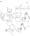
- the robot system 120 includes robots 12A and 12B, control devices 14A, 14B and 14C, a teaching device 16, a host controller 18, a mode switching device 20, peripheral devices 122, and a communication network 124.
- Peripheral devices 122 are, for example, belt conveyors, automatic guided vehicles (AGV), etc., and are arranged around the robots 12A and 12B to assist the robots 12A and 12B in their work.
- AGV automatic guided vehicles
- the controllers 14A, 14B, and 14C control the operations of the robot 12A, the robot 12B, and the peripheral device 122, respectively.
- the communication network 124 is, for example, a LAN such as an intranet, or the Internet, and connects the control devices 14A, 14B and 14C and the host controller 18 so as to be able to communicate with each other.
- host controller 18 is installed in a first building, while robots 12A and 12B, controllers 14A, 14B and 14C, teaching device 16, mode switching device 20, and peripheral device 122 are installed in the first building. It is installed in a second building (that is, a production line) that is separate from the first building.
- the host controller 18 gives commands to the control devices 14A, 14B and 14C through the communication network 124 according to a pre-determined production management scheme, and individually operates the robot 12A, the robot 12B, and the peripheral equipment 122, thereby get the job done.
- Each of the controllers 14A, 14B and 14C, the teaching device 16, the host controller 18, and the mode switching device 20 constitutes a tool having a function FC.
- the device 110 described above (that is, the image generation unit 112, the tool switching unit 114, the input reception unit 116, and the operation mode setting unit 118) is controlled by any one of the control devices 14A, 14B and 14C, the teaching device 16, and the host controller 18.
- the controller 14A, 14B or 14C, the teaching device 16, or the processor 40, 60 or 80 of the host controller 18 functions as the device 110.
- FIG. 1 the controller 14A, 14B or 14C, the teaching device 16, or the processor 40, 60 or 80 of the host controller 18 functions as the device 110.
- the control devices 14A and 14B each select the operation mode OM selected by the function FC of the mode switching device 20 (that is, "T1" (teaching mode OM1), "T2" (operation confirmation mode OM2), or In “AUTO” (automatic operation mode OM3)), the robots 12A and 12B are operated respectively.
- the operator can collectively select the operation modes OM of the robots 12A and 12B by the mode switching device 20 in which the function FC is enabled.
- the controller 14C may be omitted from the robot system 120, and the host controller 18 may directly give commands to the peripheral device 122 to control the peripheral device 122.
- the tool switching unit 114 when a plurality of tools 14 (14A, 14B, 14C), 16, 18, 20 each having a function FC are connected to the device 110 at the same time, the tool switching unit 114
- the tool's function FC may be temporarily disabled.
- the device 110 is mounted on the control device 14A, and the control devices 14B and 14C, the teaching device 16, and the host controller 18 are connected to the control device 14A.
- the processor 40 of the controller 14A outputs a signal SC_B indicating that the controller 14B is connected, a signal SC_C that indicates that the controller 14C is connected, and a signal S that indicates that the teaching device 16 is connected.
- T and a signal SH indicating that the host controller 18 is connected are obtained from the control devices 14B and 14C, the teaching device 16, and the host controller 18, respectively.
- the processor 40 of the controller 14A determines that the controllers 14B and 14C, the teaching device 16, and the host controller 18 simultaneously send signals to the controller 14A (that is, the device 110). You can recognize that you are connected. At this time, the processor 40 of the control device 14A functions as the tool switching section 114 and temporarily disables the function FC of the control devices 14B and 14C, the teaching device 16, and the host controller 18.
- FIG. 1 the processor 40 of the controller 14A determines that the controllers 14B and 14C, the teaching device 16, and the host controller 18 simultaneously send signals to the controller 14A (that is, the device 110). You can recognize that you are connected. At this time, the processor 40 of the control device 14A functions as the tool switching section 114 and temporarily disables the function FC of the control devices 14B and 14C, the teaching device 16, and the host controller 18.
- the operator is prohibited from operating the control device 14B or 14C, the teaching device 16, or the input device 46, 66 or 86 of the host controller 18 to select the operation mode OM of the robots 12A and 12B.
- the teaching device 16, or the host controller 18 may generate a warning signal indicating that the is disabled.
- control device 14A After that, the operator operates the input device 46 of the control device 14A to switch the tool for enabling the function FC through the tool switching image data 212 displayed in the image data 210 of FIG. Input IPs for switching to 14C, teaching device 16, or host controller 18 are provided to control device 14A.
- the processor 40 of the control device 14A functions as the tool switching unit 114 and selects the tool for enabling the function FC according to the signal SIP of the input IPs. Or switch to host controller 18 (i.e. second tool) and operator can select operation mode OM of robots 12A and 12B using function FC of said second tool 14A, 14B, 14C, 16 or 18 becomes.
- the mode switching device 20 given the highest priority is connected to the control device 14A.
- the processor 40 of the control device 14A may automatically switch the tool enabling the function FC to the mode switching device 20 having the highest priority.
- mode switching device 20 when mode switching device 20 is simultaneously connected to controller 14A in addition to controllers 14B and 14C, teach device 16, and host controller 18, processor 40 of controller 14A may , 14C, teaching device 16, host controller 18, and mode switching device 20 may be temporarily disabled.
- the tool switching unit 114 switches the function FC of the plurality of tools. is temporarily disabled. According to this configuration, it is possible to reliably prevent the operation mode OM from being selected with a plurality of tools 14 (14A, 14B, 14C), 16, 18, 20, thereby ensuring operator safety. .
- control device 14 (14A, 14B, 14C), the teaching device 16, the host controller 18, and the mode switching device 20, which are physical devices, are exemplified as tools having the function FC.
- any type of equipment may be connected to the robot system 10 or 120 (that is, the device 110) as a tool having the function FC.
- a tool with a functional FC is not limited to physical equipment, and may be software.
- another computer 150 (not shown) is connected to the controller 14, and multiple tools A and B as software are installed in the computer 150.
- Each of these tools A and B is configured to be able to execute the function FC on software.
- the operator can operate the input device (keyboard, etc.) of the computer 150 to activate the tool A or B on the computer 150, and use the function FC of the tool A or B to select the operation mode OM. ing.
- the tool switching unit 114 switches the tool whose function FC is valid among the control device 14, the teaching device 16, the host controller 18, the mode switching device 20, the tool A, and the tool B.
- the processor 60 of the teaching device 16 generates image data 210 shown in FIG. ' (control device 14), 'teaching device' (teaching device 16), 'host controller' (host controller 18), 'mode switching device' (mode switching device 20), 'tool A' and 'tool B'. can be displayed explicitly.
- a tool having a function FC is not limited to physical equipment, and may be configured from software.
- the teaching device 16 performs the function of teaching the motion of the robot 12 (or the robots 12A and 12B) has been described.
- the robot teaching function is not limited to this, and may be implemented in the control device 14 (or the control device 14A, 14B or 14C), for example.
- two or more teaching devices 16, upper controllers 18, or mode switching devices 20 may be connected to the control device 14.
- the input reception unit 116 and the image generation unit 112 can be omitted from the device 110 .
- the processor 40 without accepting input IPs from the operator, according to the priority, The tools that enable feature FC can be switched between a plurality of tools 14 (14A, 14B, 14C), 16, 18, 20.
- FIG. 1
- the device 110 that is, the image generation unit 112, the tool switching unit 114, the input reception unit 116, and the operation mode setting unit 118
- the functions of the device 110 may be implemented in the control device 14 or the host controller 18, for example.
- the processor 40 or 80 of the controller 14 or higher controller 18 functions as the device 110 .
- the processor 40 continues the optional operation mode OM4 and instructs the teaching device 16'.
- the robot 12 may be caused to perform a jog operation, a trial operation, or an automatic operation in accordance with a teaching command CMt, an operation confirmation command CMv, or an automatic operation start command CMa from.
- the processor 40 may enable the functional FC of the connected tool 16, 18 or 20. good.
- the teaching device 16 with the function FC is connected to the control device 14 during the optional operation mode OM4.
- the processor 40 of the control device 14 acquires the signal ST indicating that the teaching device 16 has been connected, functions as the tool switching section 114, and switches the function FC of the teaching device 16 according to the signal ST . is valid. Accordingly, the operator can select the operation mode OM of the robot 12 by operating the teaching device 16 using the function FC. It should be noted that if a plurality of tools 16, 18 and 20, each given a priority as described above, are connected to controller 14 during optional operation mode OM4, processor 40 will determine which tool 20 has the highest priority. Function FC may be enabled.
- processor 40 of controller 14 may automatically switch operation mode OM from teaching mode OM1, operation confirmation mode OM2, or automatic operation mode OM3 to optional operation mode OM4.
- the operator may apply an external force F to any part of the robot 12 (for example, the end effector 32).
- the processor 40 of the control device 14 obtains detection data of the external force F detected by the force sensor 36, and obtains the magnitude and direction of the external force F based on the detection data.
- the processor 40 operates the robot 12 according to the detected external force F to move the end effector 32 in the direction of the applied external force F (so-called direct teaching function DT).
- the robot 12 moves the end effector 32 in the direction of the external force F applied by the operator, thereby performing work in cooperation with the operator.
- the processor 40, 60 or 80 When the processor 40, 60 or 80 acquires the information IDr identifying the robot 12 as a collaborative robot, the processor 40, 60 or 80 functions as the operation mode setting unit 118 to set the predetermined operation mode instead of the arbitrary operation mode OM4 described above.
- OM may be set and fixed.
- the processor 40, 60 or 80 may set the direct teach mode OM5 according to the information IDr.
- This direct teaching mode OM5 is an operation mode OM that causes the processor 40 of the control device 14 to perform the above-described direct teaching function DT. Therefore, the operator can move the robot 12 in any direction by applying an external force F to the robot 12 in the direct teaching mode OM5.
- the processor 40, 60 or 80 acquires the signal SR from the control device 14 and functions as the operation mode setting unit 118. Then, a direct teach mode setting command CM5 is given to the controller 14 according to the information IDr attached to the signal SR .
- the processor 40 of the control device 14 receives the direct teach mode setting command CM5, it sets the operation mode OM of the robot 12 to the direct teach mode OM5 and fixes the operation mode OM of the robot 12 to the direct teach mode OM5.
- the processor 40 becomes ready to execute the direct teaching function DT.
- the processor 40, 60 or 80 recognizes that the tool 20 given the highest priority is connected to the device 110 during the direct teach mode OM5, the function FC of the tool 20 is is enabled, and the operation mode OM can be switched to the teaching mode OM1, the operation confirmation mode OM2, or the automatic operation mode OM3 by the function FC.
- the processor 40 of the controller 14 may automatically switch the operation mode OM from the teaching mode OM1, the operation confirmation mode OM2, or the automatic operation mode OM3 to the direct teaching mode OM5.
- the functions of the device 110 are implemented in the control device 14 and the tools 16, 18 and 20 having the function FC are not connected to the control device 14.
- the processor 40 of the control device 14 functions as the operation mode setting unit 118 to set the above-described direct teaching mode OM5. good too.
- the processor 40 changes the operation mode OM from the direct teach mode OM5 to an arbitrary operation mode. It may be automatically switched to mode OM4. In this case, the processor 40 causes the robot 12 to perform a jog operation, a trial operation, or an automatic operation in accordance with the teaching command CMt, the operation confirmation command CMv, or the automatic operation start command CMa from the teaching device 16' as the arbitrary operation mode OM4. may be executed.
- the operation mode OM is not limited to the teaching mode OM1, operation confirmation mode OM2, automatic operation mode OM3, arbitrary operation mode OM4, and direct teaching mode OM5 described above.
- the operation mode OM includes a high-speed operation mode in which the robot 12 is operated at a speed higher than the normal speed, and a high-precision operation mode in which the robot 12 is operated at a speed lower than the normal speed to increase the positioning accuracy of the teaching point TP (or the movement path MP).
- Any operation mode may be included, such as an operation mode, an energy-saving operation mode that reduces the power consumption of the robot 12, or the like.
- the robot 12 is not limited to a vertical multi-joint robot, and may be any type of robot such as a horizontal multi-joint robot or a parallel sync robot.
- a vertical multi-joint robot any type of robot such as a horizontal multi-joint robot or a parallel sync robot.
- robot system 12 robot 14 control device 16 teaching device 18 host controller 20 mode switching device 40, 60, 80 processor 102 physical switch 110 device 112 image generation unit 114 tool switching unit 116 input reception unit 118 operation mode setting unit
Landscapes
- Engineering & Computer Science (AREA)
- Robotics (AREA)
- Mechanical Engineering (AREA)
- Physics & Mathematics (AREA)
- General Physics & Mathematics (AREA)
- Automation & Control Theory (AREA)
- Numerical Control (AREA)
- Manipulator (AREA)
Priority Applications (7)
| Application Number | Priority Date | Filing Date | Title |
|---|---|---|---|
| CN202280089778.7A CN118647487A (zh) | 2022-01-31 | 2022-01-31 | 对具有选择动作模式的功能的工具进行切换的装置、示教装置、控制装置、机器人系统以及方法 |
| PCT/JP2022/003626 WO2023145083A1 (ja) | 2022-01-31 | 2022-01-31 | 動作モードを選択する機能を有するツールを切り換える装置、教示装置、制御装置、ロボットシステム、及び方法 |
| DE112022005637.1T DE112022005637T5 (de) | 2022-01-31 | 2022-01-31 | Gerät zum wechseln von werkzeugen mit einer funktion zum wählen der betriebsart, lehrgerät, steuergerät, roboter-system, und verfahren hierzu |
| JP2023531539A JP7460854B2 (ja) | 2022-01-31 | 2022-01-31 | 動作モードを選択する機能を有するツールを切り換える装置、教示装置、制御装置、ロボットシステム、及び方法 |
| TW112102592A TWI887599B (zh) | 2022-01-31 | 2023-01-19 | 切換具有選擇動作模式功能之工具之運算處理裝置、教示裝置、控制裝置、機器人系統及工具切換方法 |
| TW114119166A TW202533930A (zh) | 2022-01-31 | 2023-01-19 | 設定動作模式之裝置、教示裝置、控制裝置、機器人系統及方法 |
| JP2024035253A JP2024056066A (ja) | 2022-01-31 | 2024-03-07 | 動作モードを選択する機能を有するツールを切り換える装置、教示装置、制御装置、ロボットシステム、及び方法 |
Applications Claiming Priority (1)
| Application Number | Priority Date | Filing Date | Title |
|---|---|---|---|
| PCT/JP2022/003626 WO2023145083A1 (ja) | 2022-01-31 | 2022-01-31 | 動作モードを選択する機能を有するツールを切り換える装置、教示装置、制御装置、ロボットシステム、及び方法 |
Publications (1)
| Publication Number | Publication Date |
|---|---|
| WO2023145083A1 true WO2023145083A1 (ja) | 2023-08-03 |
Family
ID=87470978
Family Applications (1)
| Application Number | Title | Priority Date | Filing Date |
|---|---|---|---|
| PCT/JP2022/003626 Ceased WO2023145083A1 (ja) | 2022-01-31 | 2022-01-31 | 動作モードを選択する機能を有するツールを切り換える装置、教示装置、制御装置、ロボットシステム、及び方法 |
Country Status (5)
| Country | Link |
|---|---|
| JP (2) | JP7460854B2 (enExample) |
| CN (1) | CN118647487A (enExample) |
| DE (1) | DE112022005637T5 (enExample) |
| TW (2) | TW202533930A (enExample) |
| WO (1) | WO2023145083A1 (enExample) |
Cited By (1)
| Publication number | Priority date | Publication date | Assignee | Title |
|---|---|---|---|---|
| WO2025046677A1 (ja) * | 2023-08-28 | 2025-03-06 | ファナック株式会社 | 数値制御装置及び数値制御システム |
Citations (5)
| Publication number | Priority date | Publication date | Assignee | Title |
|---|---|---|---|---|
| JPS6140609A (ja) * | 1984-08-02 | 1986-02-26 | Amada Co Ltd | ロボツトの操作装置 |
| JPH1177571A (ja) * | 1997-09-04 | 1999-03-23 | Meidensha Corp | ロボットの教示方法、ロボットの加工制御方法及びロボット制御装置 |
| WO2006137239A1 (ja) * | 2005-06-20 | 2006-12-28 | Kabushiki Kaisha Yaskawa Denki | 自動機械システムおよびその通信制御方法 |
| JP2010052106A (ja) * | 2008-08-29 | 2010-03-11 | Digital Electronics Corp | 機器制御システム |
| JP2019195852A (ja) * | 2018-05-07 | 2019-11-14 | 川崎重工業株式会社 | 装置を動作させるためのシステム |
Family Cites Families (4)
| Publication number | Priority date | Publication date | Assignee | Title |
|---|---|---|---|---|
| JP2719460B2 (ja) * | 1991-07-09 | 1998-02-25 | ファナック株式会社 | 教示操作盤接続装置 |
| JP2796048B2 (ja) * | 1993-11-11 | 1998-09-10 | 三菱電機株式会社 | ロボット制御装置及びそのティーチングボックス |
| JP2007061965A (ja) * | 2005-08-31 | 2007-03-15 | Victor Co Of Japan Ltd | ロボット装置における起動モード設定方法 |
| JP5623050B2 (ja) | 2009-09-29 | 2014-11-12 | ソフトバンクBb株式会社 | 通信システム |
-
2022
- 2022-01-31 JP JP2023531539A patent/JP7460854B2/ja active Active
- 2022-01-31 DE DE112022005637.1T patent/DE112022005637T5/de active Pending
- 2022-01-31 CN CN202280089778.7A patent/CN118647487A/zh active Pending
- 2022-01-31 WO PCT/JP2022/003626 patent/WO2023145083A1/ja not_active Ceased
-
2023
- 2023-01-19 TW TW114119166A patent/TW202533930A/zh unknown
- 2023-01-19 TW TW112102592A patent/TWI887599B/zh active
-
2024
- 2024-03-07 JP JP2024035253A patent/JP2024056066A/ja active Pending
Patent Citations (5)
| Publication number | Priority date | Publication date | Assignee | Title |
|---|---|---|---|---|
| JPS6140609A (ja) * | 1984-08-02 | 1986-02-26 | Amada Co Ltd | ロボツトの操作装置 |
| JPH1177571A (ja) * | 1997-09-04 | 1999-03-23 | Meidensha Corp | ロボットの教示方法、ロボットの加工制御方法及びロボット制御装置 |
| WO2006137239A1 (ja) * | 2005-06-20 | 2006-12-28 | Kabushiki Kaisha Yaskawa Denki | 自動機械システムおよびその通信制御方法 |
| JP2010052106A (ja) * | 2008-08-29 | 2010-03-11 | Digital Electronics Corp | 機器制御システム |
| JP2019195852A (ja) * | 2018-05-07 | 2019-11-14 | 川崎重工業株式会社 | 装置を動作させるためのシステム |
Cited By (1)
| Publication number | Priority date | Publication date | Assignee | Title |
|---|---|---|---|---|
| WO2025046677A1 (ja) * | 2023-08-28 | 2025-03-06 | ファナック株式会社 | 数値制御装置及び数値制御システム |
Also Published As
| Publication number | Publication date |
|---|---|
| JP7460854B2 (ja) | 2024-04-02 |
| TWI887599B (zh) | 2025-06-21 |
| JP2024056066A (ja) | 2024-04-19 |
| TW202346042A (zh) | 2023-12-01 |
| DE112022005637T5 (de) | 2024-09-19 |
| JPWO2023145083A1 (enExample) | 2023-08-03 |
| CN118647487A (zh) | 2024-09-13 |
| TW202533930A (zh) | 2025-09-01 |
Similar Documents
| Publication | Publication Date | Title |
|---|---|---|
| JP6266300B2 (ja) | 工作機械 | |
| JP2013528121A (ja) | 産業用ロボットの運動又はシーケンスをプログラミング又は設定する方法 | |
| JP4905451B2 (ja) | 自動機械システム | |
| JP7108103B2 (ja) | 機械の教示に用いる機械教示端末、教示システム、プログラム及び安全確認方法 | |
| US20170312912A1 (en) | Robot control apparatus which displays operation program including state of additional axis | |
| JP7460854B2 (ja) | 動作モードを選択する機能を有するツールを切り換える装置、教示装置、制御装置、ロボットシステム、及び方法 | |
| JP2014117774A (ja) | ロボット制御システム | |
| US11358281B2 (en) | Control method by robot system and robot system | |
| JP6414317B2 (ja) | 産業機械システム | |
| KR102403021B1 (ko) | 로봇 교시 장치 및 이를 이용한 로봇 교시 방법 | |
| TWI895687B (zh) | 雷射加工系統及雷射加工方法 | |
| JP2008093743A (ja) | 自動機械システム | |
| JP7594643B2 (ja) | ロボットシステム | |
| WO2024134902A1 (ja) | ロボットの姿勢を調整する装置、方法、及びコンピュータプログラム | |
| KR20170055845A (ko) | 용접 로봇 제어시스템 및 그의 로봇 인식방법 | |
| EP4461476A1 (en) | Operating device and program | |
| WO2023162248A1 (ja) | 教示操作盤およびロボット制御システム | |
| JP4213990B2 (ja) | ロボットの教示装置 | |
| TWI901964B (zh) | 機器人之控制裝置、機器人系統、及機器人之控制方法 | |
| CN112743539A (zh) | 机器人系统 | |
| WO2024004170A1 (ja) | ロボットの制御装置、ロボットシステム、及びロボットの制御方法 | |
| JP3174218B2 (ja) | 工業用ロボットの制御方法 | |
| US20250238017A1 (en) | Method for switching between operational modes in tele-manufacturing systems | |
| CN113905857A (zh) | 示教系统 | |
| JP2005118968A (ja) | ロボットシステム |
Legal Events
| Date | Code | Title | Description |
|---|---|---|---|
| WWE | Wipo information: entry into national phase |
Ref document number: 2023531539 Country of ref document: JP |
|
| 121 | Ep: the epo has been informed by wipo that ep was designated in this application |
Ref document number: 22923946 Country of ref document: EP Kind code of ref document: A1 |
|
| WWE | Wipo information: entry into national phase |
Ref document number: 202280089778.7 Country of ref document: CN |
|
| 122 | Ep: pct application non-entry in european phase |
Ref document number: 22923946 Country of ref document: EP Kind code of ref document: A1 |