WO2023145083A1 - 動作モードを選択する機能を有するツールを切り換える装置、教示装置、制御装置、ロボットシステム、及び方法 - Google Patents
動作モードを選択する機能を有するツールを切り換える装置、教示装置、制御装置、ロボットシステム、及び方法 Download PDFInfo
- Publication number
- WO2023145083A1 WO2023145083A1 PCT/JP2022/003626 JP2022003626W WO2023145083A1 WO 2023145083 A1 WO2023145083 A1 WO 2023145083A1 JP 2022003626 W JP2022003626 W JP 2022003626W WO 2023145083 A1 WO2023145083 A1 WO 2023145083A1
- Authority
- WO
- WIPO (PCT)
- Prior art keywords
- robot
- tool
- mode
- teaching
- function
- Prior art date
Links
- 238000000034 method Methods 0.000 title claims description 5
- 230000006870 function Effects 0.000 claims description 137
- 238000012790 confirmation Methods 0.000 claims description 63
- 230000033001 locomotion Effects 0.000 claims description 29
- 230000002093 peripheral effect Effects 0.000 claims description 9
- 230000009471 action Effects 0.000 claims description 3
- 230000008859 change Effects 0.000 abstract description 8
- 239000012636 effector Substances 0.000 description 12
- 230000004044 response Effects 0.000 description 9
- 210000000707 wrist Anatomy 0.000 description 7
- 238000010586 diagram Methods 0.000 description 5
- 238000004891 communication Methods 0.000 description 4
- 238000004519 manufacturing process Methods 0.000 description 3
- 230000005540 biological transmission Effects 0.000 description 2
- 238000004590 computer program Methods 0.000 description 2
- 238000001514 detection method Methods 0.000 description 2
- 238000003466 welding Methods 0.000 description 2
- 239000004973 liquid crystal related substance Substances 0.000 description 1
- 230000007246 mechanism Effects 0.000 description 1
- 239000013307 optical fiber Substances 0.000 description 1
Images


Classifications
-
- B—PERFORMING OPERATIONS; TRANSPORTING
- B25—HAND TOOLS; PORTABLE POWER-DRIVEN TOOLS; MANIPULATORS
- B25J—MANIPULATORS; CHAMBERS PROVIDED WITH MANIPULATION DEVICES
- B25J9/00—Programme-controlled manipulators
- B25J9/16—Programme controls
- B25J9/1656—Programme controls characterised by programming, planning systems for manipulators
-
- G—PHYSICS
- G05—CONTROLLING; REGULATING
- G05B—CONTROL OR REGULATING SYSTEMS IN GENERAL; FUNCTIONAL ELEMENTS OF SUCH SYSTEMS; MONITORING OR TESTING ARRANGEMENTS FOR SUCH SYSTEMS OR ELEMENTS
- G05B19/00—Programme-control systems
- G05B19/02—Programme-control systems electric
- G05B19/42—Recording and playback systems, i.e. in which the programme is recorded from a cycle of operations, e.g. the cycle of operations being manually controlled, after which this record is played back on the same machine
Definitions
- the present disclosure relates to a device, a teaching device, a control device, a robot system, and a method for switching tools having a function of selecting an operation mode.
- Patent Document 1 A tool that has a function of switching the operation mode of a robot is known (for example, Patent Document 1).
- a device for switching tools having a function of selecting an operation mode of a robot includes a tool switching unit that switches a tool whose function is to be enabled from a first tool to a second tool.
- a method for switching a tool having a function of selecting an operation mode of a robot is performed by a processor switching the tool for which the function is enabled from a first tool to a second tool.
- the operator can easily switch tools that enable the function of selecting the operation mode without adding software or changing settings.
- the work involved in constructing or modifying the robot system can be simplified.
- FIG. 1 is a schematic diagram of a robot system according to one embodiment
- FIG. 2 is a block diagram of the robot system shown in FIG. 1
- FIG. 2 is a schematic diagram of the mode switching device shown in FIG. 1
- FIG. An example of the mode selection image data for selecting driving mode is shown.
- An example of image data for inputting tool switching is shown.
- 2 is a block diagram showing another function of the robot system shown in FIG. 1;
- FIG. Another example of image data for inputting tool switching is shown.
- It is a schematic diagram of a robot system according to another embodiment.
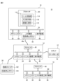
- FIG. 1 The robot system 10 includes a robot 12 , a control device 14 , a teaching device 16 , a host controller 18 and a mode switching device 20 .
- the robot 12 is a vertical multi-joint robot and has a robot base 22 , a swing trunk 24 , a lower arm section 26 , an upper arm section 28 , a wrist section 30 and an end effector 32 .
- the robot base 22 is fixed on the floor of the work cell or on an automated guided vehicle (AGV).
- the swing barrel 24 is provided on the robot base 22 so as to be rotatable about a vertical axis.
- the lower arm 26 is provided on the swing barrel 24 so as to be rotatable about the horizontal axis, and the upper arm 28 is rotatably provided at the tip of the lower arm 26 .
- the wrist portion 30 is provided at the distal end portion of the upper arm portion 28 so as to be rotatable about two axes perpendicular to each other.
- the end effector 32 is detachably attached to the tip of the wrist 30 (so-called wrist flange).
- the end effector 32 is a robot hand, a welding torch, a laser processing head, or the like, and performs predetermined work (work handling, welding, laser processing, etc.) on the work.
- a plurality of servo motors 34 are provided in the robot base 22, the swing body 24, the lower arm section 26, the upper arm section 28, and the wrist section 30, respectively.
- the servomotor 34 rotates each movable component of the robot 12 (that is, the swing body 24, the lower arm 26, the upper arm 28, and the wrist 30) around the drive shaft in response to commands from the control device 14. Let In this way, the robot 12 operates according to commands from the control device 14 to move the end effector 32 to an arbitrary target position.
- controller 14 controls the motion of the robot 12 .
- controller 14 is a computer having processor 40 , memory 42 , I/O interface 44 , input device 46 , and display device 48 .
- the processor 40 has a CPU, GPU, or the like, is communicatively connected to a memory 42, an I/O interface 44, an input device 46, and a display device 48 via a bus 50, and controls the robot while communicating with these components. Arithmetic processing is performed to realize functions.
- the memory 42 has RAM, ROM, etc., and temporarily or permanently stores various data.
- the I/O interface 44 has, for example, an Ethernet (registered trademark) port, a USB port, an optical fiber connector, or an HDMI (registered trademark) terminal, and exchanges data with external devices under instructions from the processor 40. Communicate by wire or wirelessly.
- the input device 46 has push buttons, a keyboard, a mouse, a touch panel, or the like, and receives input data from the operator.
- the display device 48 has a liquid crystal display, an organic EL display, or the like, and visually displays various data under commands from the processor 40 .
- the input device 46 and the display device 48 may be integrated into the housing of the control device 14, or may be externally attached to the housing of the control device 14 as separate bodies. .
- the teaching device 16 teaches the robot 12 a predetermined motion.
- the teaching device 16 is, for example, a portable computer such as a teaching pendant or tablet terminal device, and has a processor 60, a memory 62, an I/O interface 64, an input device 66, and a display device 68.
- the configurations of the processor 60, memory 62, I/O interface 64, input device 66, and display device 68 are the same as those of the processor 40, memory 42, I/O interface 44, input device 46, and display device 48 described above. Therefore, redundant description is omitted.
- the input device 66 and the display device 68 are integrated in the housing 16a of the teaching device 16, as shown in FIG.
- the input device 66 includes an emergency stop button 66a.
- the emergency stop button 66a is for stopping the robot 12 in an emergency.
- the processor 60 is communicatively connected to a memory 62, an I/O interface 64, an input device 66, and a display device 68 via a bus 70, and communicates with these components to perform arithmetic processing for realizing teaching functions. conduct.
- the processor 60 of the teaching device 16 sends teaching commands CMt to the servo motors 34 of the robot 12 via the control device 14 according to input data to the input device 66, and jogs the robot 12 according to the teaching commands CMt. It is configured so that it can be The operator operates the input device 66 to teach the robot 12 a predetermined motion, and the processor 60 generates a motion program PG that causes the robot 12 to perform the taught predetermined motion.
- the host controller 18 gives commands to the control device 14 to control the control device 14 .
- the host controller 18 is, for example, a programmable logic controller (PLC) or a computer such as a desktop PC, and includes a processor 80, a memory 82, an I/O interface 84, an input device 86, and a display device 88.
- PLC programmable logic controller
- the configurations of the processor 80, memory 82, I/O interface 84, input device 86, and display device 88 are the same as those of the processor 40, memory 42, I/O interface 44, input device 46, and display device 48 described above. Therefore, redundant description is omitted.
- Processor 80 is communicatively connected to memory 82, I/O interface 84, input device 86, and display device 88 via bus 90, and while communicating with these components, performs arithmetic processing for realizing host control functions. I do. For example, the processor 80 sends a command to the control device 14 according to a pre-determined production management scheme, and operates the robot 12 under the control of the control device 14 to perform a predetermined work.
- the mode switching device 20 has a function FC for selecting one of a plurality of operation modes OM in which the controller 14 operates the robot 12 .
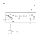
- An example of the mode switching device 20 is shown in FIG.
- Mode switching device 20 has housing 100 , physical switch 102 , emergency stop button 104 , program execution button 108 and physical key 106 .
- the housing 100 is hollow and accommodates therein electronic components (such as LSIs) that implement the functions of the mode switching device 20 .
- the physical switch 102 is for selecting one of a plurality of operation modes OM of the robot 12, and is rotatably provided on the housing 100 so as to be exposed to the outside of the housing 100. .
- the operation mode OM includes a teaching mode OM1, an operation confirmation mode OM2, and an automatic operation mode OM3.
- the teaching mode OM1 is an operation mode OM in which the operator teaches the robot 12 a predetermined operation using the teaching device 16 to create an operation program PG for the robot 12 .
- the operator operates the input device 66 of the teaching device 16 to give a teaching command CMt to the control device 14, and the control device 14 jogs the robot 12 according to the teaching command CMt.
- an operator instructs the robot 12 to provide a plurality of teaching points TP for positioning an end effector (or TCP) when performing work on a workpiece, and a plurality of teaching points TP defined by the teaching points TP. It teaches the movement path MP of the end effector (or TCP).
- the operator teaches the robot 12 a predetermined motion for performing work on the work.
- the operator operates the robot 12 at the first speed V1 in order to teach the robot 12 a predetermined motion.
- the processor 40 of the control device 14 limits the movement speed of the robot 12 (for example, the end effector 32) to a first speed V1 or less.
- the operation confirmation mode OM2 is an operation mode OM that causes the robot 12 to try a predetermined operation taught in the teaching mode OM1 in order to confirm the predetermined operation.
- the operator causes the robot 12 to test-execute the incomplete motion program PG′ generated during the teaching in the teaching mode OM1, thereby instructing the robot 12 to perform the motion taught (that is, the motion). Appropriateness of program PG').
- the operator operates the input device 66 of the teaching device 16 to give an operation confirmation command CMv to the controller 14, and the controller 14 instructs the robot 12 according to the operation confirmation command CMv.
- the robot 12 is operated at a second speed V2 (>V1) higher than the first speed V1 according to the motion program PG' created at this time.
- the processor 40 in order to confirm the operation taught to the robot 12 (specifically, the operation of the robot 12 according to the operation program PG'), the processor 40 follows the operation confirmation command CMv to perform the operation at a higher speed. to operate the robot 12 at a second speed V2 of .
- the second speed V2 is, for example, the speed defined in the operation program PG'.
- the operator confirms the attempted motion of the robot 12 in the motion confirmation mode OM2, executes the teaching mode OM1 again, and adds or corrects the teaching point TP (or movement path MP) defined in the motion program PG'. do.
- the processor 60 generates a formal motion program PG for executing work on the workpiece, and provides the generated motion program PG to the controller 14 .
- operation program PG operation conditions such as the speed V3 of the robot 12 are defined together with the taught point TP and movement path MP.
- the processor 40 of the control device 14 is operating the robot 12 in the teaching mode OM1 and the operation confirmation mode OM2, tools other than the teaching device 16 (that is, the control device 14, the host controller 18, the mode switching device 20) It is prohibited to command the execution of the operation program PG (or PG') from the input devices (input devices 46, 66, 86).
- the automatic operation mode OM3 is, for example, an operation mode OM in which the robot 12 is automatically operated according to the operation program PG in order to cause the robot 12 to perform actual work on the workpiece within the work cell.
- the operator operates the program execution button 108 of the mode switching device 20 or the input device 86 of the host controller 18 to give the automatic operation start command CMa to the control device 14 .
- the processor 40 of the control device 14 starts the automatic operation mode OM3, and automatically operates the robot 12 according to the operation program PG at the speed V3 specified in the operation program PG. .
- This speed V3 can be equal to or higher than the above speed V2 (V3 ⁇ V2).
- transmission of the automatic operation start command CMa from the input device 66 of the teaching device 16 to the control device 14 is prohibited.
- transmission of the teaching command CMt and the operation confirmation command CMv from the input device 66 of the teaching device 16 to the control device 14 is prohibited during the automatic operation mode OM3.
- the I/O interface 44 of the control device 14 includes the servo motors 34 of the robot 12, the I/O interface 64 of the teaching device 16, the I/O interface 84 of the host controller 18, and , the mode switching device 20 (specifically, the physical switch 102, the emergency stop button 104, and the program execution button 108) so as to be able to communicate by wire or wirelessly.
- the physical switch 102 selects one of the above-described teaching mode OM1, operation confirmation mode OM2, and automatic operation mode OM3.
- "AUTO”, “T1”, and “T2” are displayed on the housing 100, and the physical switch 102 rotates with respect to the housing 100 so that these "AUTO”, “T1”, and “T2” are displayed.
- "T1" or "T2" can be selected.
- AUTO corresponds to the automatic operation mode OM3
- T1 corresponds to the teaching mode OM1
- T2 corresponds to the operation confirmation mode OM2.
- the operator selects the operation mode OM to be executed by the control device 14 from “AUTO” (automatic operation mode OM3), "T1” (teaching mode OM1), and “T2” (operation mode OM3).
- a confirmation mode OM2) can be selected. Note that FIG. 3 shows a state in which the physical switch 102 selects “AUTO” (automatic operation mode OM3).
- the mode switching device 20 transmits a teaching mode selection command CM1 to the control device 14, and changes the operation mode OM executed by the control device 14 to the teaching mode. Go to OM1.
- the operator can use the teaching device 16 to operate the robot 12 at the first speed V1 via the control device 14 in the teaching mode OM1 to teach the robot 12 the motion.
- the mode switching device 20 transmits an operation confirmation mode selection command CM2 to the control device 14, and selects the operation mode OM executed by the control device 14. to the operation check mode OM2.
- the operator uses the teaching device 16 to operate the robot 12 at the second speed V2 via the control device 14 in the operation confirmation mode OM2, and confirms the operation taught to the robot 12 (for example, operation operation confirmation of the program PG').
- the mode switching device 20 transmits an automatic operation mode selection command CM3 to the control device 14, and the operation mode OM is executed by the control device 14. to the automatic operation mode OM3.
- the operator can operate the program execution button 108 of the mode switching device 20 or the host controller 18 to automatically operate the robot 12 according to the operation program PG.
- the physical key 106 can be inserted into and removed from a keyhole 102a formed in the physical switch 102.
- the physical switch 102 can be rotated. 102 becomes operational.
- the rotation of the physical switch 102 is restricted and the physical switch 102 becomes inoperable.
- the program execution button 108 can cause the control device 14 to start the automatic operation mode OM3. Specifically, the operator operates the program execution button 108 with "AUTO" selected by the physical switch 102 . Then, the mode switching device 20 transmits the automatic operation start command CMa to the control device 14 following the automatic operation mode selection command CM3.
- the processor 40 of the control device 14 shifts the operation mode OM to the automatic operation mode OM3 in response to the automatic operation mode selection command CM3. As a result, the processor 40 becomes ready to accept the automatic operation start command CMa, but prohibits acceptance of the teaching command CMt and the operation confirmation command CMv.
- the processor 40 causes the robot 12 to automatically operate according to the operation program PG as described above.
- the emergency stop button 104 is for stopping the robot 12 in an emergency.
- the processor 40 of the control device 14 automatically operates the robot 12 in the automatic operation mode OM3 (or operates the robot 12 according to the operation program PG' in the operation confirmation mode OM2)
- the operator When emergency stop button 104 is pressed, mode switching device 20 gives control device 14 an emergency stop command CMs.
- the control device 14 In response to the emergency stop command CMs, the control device 14, for example, stops the command (current command) to each servomotor 34, or activates a brake mechanism that brakes the rotating shaft of each servomotor 34. , the robot 12 is brought to an emergency stop.
- the mode switching device 20 has a function FC for selecting the operation mode OM (that is, the teaching mode OM1, the operation confirmation mode OM2, or the automatic operation mode OM3) in which the robot 12 is operated by the control device 14.
- the teaching device 16 like the mode switching device 20, has a function FC for selecting the operation mode OM of the robot 12.
- processor 60 of teaching device 16 generates mode selection image data 200 for accepting selection of operation mode OM, and displays it on display device 68 .
- FIG. 4 shows an example of the mode selection image data 200. As shown in FIG.
- the mode selection image data 200 is a graphical user interface (GUI) that allows the operator to select the operation mode OM, and includes T1 button image data 202, T2 button image data 204, and AUTO button image data 206.
- GUI graphical user interface
- the T1 button image data 202, the T2 button image data 204, and the AUTO button image data 206 correspond to the teaching mode OM1, the operation confirmation mode OM2, and the automatic operation mode OM3, respectively.
- the operator clicks on the image of the T1 button image data 202, the T2 button image data 204, or the AUTO button image data 206 to select the teaching mode OM1 and the operation confirmation mode.
- OM2 or automatic operation mode OM3 can be selected.
- processor 60 when processor 60 receives input IPm for selecting T1 button image data 202 in mode selection image data 200 from input device 66, processor 60 transmits teaching mode selection command CM1 to control device 14, and control device 14 to the teaching mode OM1.
- the processor 60 when the processor 60 receives an input IPm for selecting the T2 button image data 204 from the input device 66, the processor 60 transmits an operation confirmation mode selection command CM2 to the control device 14, and selects the operation mode OM executed by the control device 14 as an operation mode. It shifts to confirmation mode OM2.
- the processor 60 receives the input IPm for selecting the AUTO button image data 206 from the input device 66, it transmits an automatic operation mode selection command CM3 to the control device 14, and selects the operation mode OM executed by the control device 14 as automatic.
- the operation teaching mode OM3 is entered.
- the processor 60 transmits an emergency stop command CMs to the control device 14, Make an emergency stop.
- the processor 80 of the host controller 18 generates mode selection image data 200 and displays it on the display device 88 in the same manner as the teaching device 16 .
- processor 80 receives input IPm for selecting T1 button image data 202, T2 button image data 204, or AUTO button image data 206 from input device 86, processor 80 issues teaching mode selection command CM1, operation check mode selection command CM2, or An automatic operation mode selection command CM3 is transmitted to the control device 14, and the operation mode OM executed by the control device 14 is shifted to the teaching mode OM1, the operation confirmation mode OM2, or the automatic operation teaching mode OM3.
- control device 14 also has a function FC for selecting the operation mode OM of the robot 12, like the teaching device 16.
- input device 46 of controller 14 may include physical switch 102 described above.
- the operator operates the physical switch 102 to select "AUTO” (automatic operation mode OM3), "T1" (teaching mode OM1), or "T2" (operation confirmation mode OM2).
- AUTO automatic operation mode OM3
- T1 teaching mode OM1
- T2 operation confirmation mode OM2
- the processor 40 of the control device 14 generates the mode selection image data 200 and displays it on the display device 48 in the same way as the teaching device 16 does.
- processor 40 receives input IPm for selecting T1 button image data 202, T2 button image data 204, or AUTO button image data 206 from input device 46
- processor 40 issues teaching mode selection command CM1, operation check mode selection command CM2, or
- An automatic operation mode selection command CM3 is transmitted to the control device 14, and the operation mode OM executed by the control device 14 is shifted to the teaching mode OM1, the operation confirmation mode OM2, or the automatic operation teaching mode OM3.
- the processor 40 of the control device 14 Before displaying the mode selection image data 200 on the display device 48, 68 or 88, the processor 40 of the control device 14, the processor 60 of the teaching device 16, or the processor 80 of the host controller 18 receives the function FC from the operator. An input IPd of the digital key DK for enabling use may be accepted.
- the digital key DK can be, for example, a password or operator identification information (employee number, etc.).
- the processor 40, 60 or 80 receives the input IPd through the input device 46, 66 or 86, it displays the mode selection image data 200 on the display device 48, 68 or 88 so that the operator can select the operation mode OM. do.
- the processor 40, 60 or 80 generates digital key image data (not shown) for entering the digital key DK and displays it on the display device 48, 68 or 88 prior to the mode selection image data 200. You may
- each of the control device 14, the teaching device 16, the host controller 18, and the mode switching device 20 controls the operation mode OM of the robot 12 (the teaching mode OM1, the operation confirmation mode OM2, or the automatic It has a function FC for selecting the operation teaching mode OM3). Accordingly, the control device 14, the teaching device 16, the host controller 18, and the mode switching device 20 constitute tools 14, 16, 18, and 20, respectively, having a function FC for selecting the operation mode OM.
- the robot system 10 shown in FIG. 2 may further include a safety fence surrounding the robot 12.
- the teaching mode OM1 or the operation confirmation mode OM2 is selected as the operation mode OM
- the automatic operation mode OM3 is selected as the operation mode OM.
- the operation mode OM may be used separately inside and outside the safety fence.
- the processor 60 of the teaching device 16 switches the tool 14, 16, 18 or 20 for which the function FC is valid among these tools 14, 16, 18 and 20. Specifically, processor 60 generates image data 210 shown in FIG. 5 and displays it on display device 68 . Thus, in the present embodiment, processor 60 functions as image generator 112 ( FIG. 2 ) that generates image data 210 .
- the image data 210 includes tool switching image data 212 and operation mode display image data 214.
- the tool switching image data 212 is for switching the tool whose function FC is valid among the control device 14 , the teaching device 16 , the host controller 18 and the mode switching device 20 .
- the tools connected to the robot system 10 are “control device” (control device 14), “teaching device” (teaching device 16), “upper controller” (upper controller 18), and A “mode switching device” (mode switching device 20) is selectively displayed, and the operator operates the input device 66 to change the tool switching image data 212 to the control device 14, the teaching device 16, the host controller 18, or the A mode switching device 20 can be used for switching.
- the processor 60 may acquire information IDe that identifies the tools 14 , 16 , 18 or 20 that are connected to each other in the robot system 10 .
- a control device 14 a teaching device 16, a host controller 18, and a mode switching device 20 are connected.
- the processor 60 of the teaching device 16 outputs a signal SC indicating that the control device 14 is connected to the robot system 10, a signal ST indicating that the teaching device 16 is connected, and the host controller 18.
- a signal SH indicating that the mode switching device 20 has been connected and a signal SM indicating that the mode switching device 20 has been connected are sent from the control device 14, the teaching device 16, the host controller 18, and the mode switching device 20, respectively. get.
- the signal SC includes information IDe1 (eg, identification number) identifying the control device 14 as additional information
- the signal ST includes information IDe2 (eg, identification number) identifying the teaching device 16 as additional information
- the signal SH may include information IDe3 for identifying the host controller 18 as additional information
- the signal SM may include information IDe4 for identifying the mode switching device 20 as additional information.
- the processor 60 of the teaching device 16 detects the tools (that is, the control device 14 , the teaching device 16, host controller 18, and mode switching device 20) are selectively displayed in the tool switching image data 212.
- FIG. 1 The processor 60 of the teaching device 16 detects the tools (that is, the control device 14 , the teaching device 16, host controller 18, and mode switching device 20) are selectively displayed in the tool switching image data 212.
- the operation mode display image data 214 is the operation mode OM ("AUTO" in the example shown in FIG. 5) selectable by the tool (the teaching device 16 in the example shown in FIG. Automatic operation mode OM3, "T1”: teaching mode OM1, and "T2": operation confirmation mode OM2) are displayed.
- AUTO operation mode in the example shown in FIG. 5
- T1 teaching mode OM1
- T2 operation confirmation mode OM2
- a database of operation modes OM selectable by a plurality of tools 14, 16, 18 and 20 may be stored in memory 62 in advance.
- the processor 60 reads from the database the operation modes OM that can be selected by the tools 14, 16, 18 or 20 displayed in the tool switching image data 212 and displays them in the operation mode display image data 214. good.
- the information of the operating modes OM selectable by the tools 14, 16, 18 and 20 may be the signals S C , S T , S H and S M described above (e.g. identification information IDe1, IDe2, IDe3, IDe4 ) and processor 60 may obtain information of selectable modes of operation OM from said signals S C , S T , S H and S M .
- the processor 60 receives a signal SIP corresponding to the input IPs from the input device 66, and switches the tool enabling the function FC to the mode switching device 20 according to the signal SIP.
- the processor 60 enables only the function FC of the mode switching device 20 according to the signal SIP , while enabling the function FC of the control device 14, the teaching device 16, and the host controller 18, which are other tools. to the control device 14.
- the processor 40 of the control device 14 can receive the teaching mode selection command CM1, the operation confirmation mode selection command CM2, or the automatic operation mode selection command CM3 transmitted by the function FC of the mode switching device 20. Become.
- the processor 40 rejects the teaching mode selection command CM1, the operation confirmation mode selection command CM2, or the automatic operation mode selection command CM3 transmitted by the function FC of the control device 14, the teaching device 16, and the host controller 18. .
- the function FC of the mode switching device 20 designated by the tool switching image data 212 is enabled, and the mode switching device 20 can select the operation mode OM. 18 becomes invalid, and the control device 14, the teaching device 16 and the host controller 18 cannot select the operation mode OM.
- the processor 60 receives a signal SIP corresponding to the input IPs from the input device 66, and transmits a tool enabling the function FC to the teaching device 16 (or the host controller 18) according to the signal SIP. switch. Then, the processor 60 (or 80) generates mode selection image data 200 shown in FIG. Acceptable.
- the processor 40 selects tools for enabling the function FC of the control device 14, the teaching device 16, the host controller 18, and the mode switching device 20 in response to the predetermined signal SIP . switch between. Therefore, the processor 40 switches the tool that enables the function FC from the first tool (eg, the control device 14, the teaching device 16, or the host controller 18) to the second tool (eg, the mode switching device 20). It functions as the tool switching unit 114 (FIG. 2).
- the processor 40 receives input IPs for switching the tool that enables the function FC to the second tool (for example, the mode switching device 20) via the input device 66.
- the tool that enables the function FC is switched from the first tool to the second tool. Therefore, processor 40 functions as input reception unit 116 (FIG. 2) that receives input IPs.
- control device 14, the teaching device 16, the host controller 18, and the mode switching device 20 may be given a predetermined priority.
- the function FC of the mode switching device 20 should be given top priority due to safety standards for industrial robots. In this case, mode switching device 20 is given the highest priority.
- the processor 60 of the teaching device 16 outputs signals S C , S T , S H and S M are obtained from the control device 14, the teaching device 16, the upper controller 18 and the mode switching device 20, respectively.
- processor 60 recognizes from signal SM indicating connection of mode switching device 20 that mode switching device 20 given the highest priority has been connected.
- the processor 60 collects signals S C , S T , S H and S M indicating connection each time the control device 14 , the teaching device 16 , and the host controller 18 are activated (that is, turned on).
- the processor 60 functions as the tool switching unit 114, and selects the tools that enable the function FC among the connected control device 14, the teaching device 16, the host controller 18, and the mode switching device 20 in order of priority. is automatically switched to the mode switching device 20 in which is the highest. In this way, when processor 60 receives signal SM indicating that mode switching device 20 with the highest priority has been connected, processor 60 provides a tool for enabling function FC to mode switching device 20. switch automatically.
- the teaching device 16 and the host controller 18 are connected to the control device 14, and the function FC of the teaching device 16 is enabled.
- the processor 60 receives the signal SM indicating the connection of the mode switching device 20 and functions as the tool switching unit 114.
- the teaching device 16 is automatically switched to the mode switching device 20 to function and enable the function FC.
- each of the plurality of tools 14, 16, 18 and 20 may be given priority.
- the first priority is given to the mode switching device 20
- the second priority is given to the teaching device 16
- the third priority is given to the host controller 18, and the fourth priority is given to the control device 14. obtain.
- the processor 40 enables the function FC in the connected tools 14, 16, 18 and 20 upon receipt of the signals S C , S T , S H and S M indicating connection. Automatically switch tools according to priority. The priority given to the tools 14, 16, 18 and 20 can be arbitrarily determined by the operator.
- the operator may 16 or the host controller 18 to input IPs specifying a tool other than the mode switching device 20 (that is, the control device 14, the teaching device 16, or the host controller 18) through the image data 210 shown in FIG. 60 may generate a warning signal SAL indicating that the function FC of a tool other than the mode switching device 20 cannot be activated.
- the processor 60 generates a warning signal SAL of image data or audio data stating that "the function to select the operation mode cannot be used with a tool other than the mode switching device", and the display device 68 or the teaching device 16 provides It may be output through a speaker (not shown).
- the processor 60 instead of generating the warning signal S AL (or in addition to generating the warning signal S AL ), the processor 60 sends the above-described emergency stop commands CMs to the controller 14 to stop the operation of the robot 12. You can stop it.
- the processor 60 functions as the image generation unit 112, the tool switching unit 114, and the input reception unit 116, and the operation mode OM (teaching mode OM1, operation confirmation mode OM2) of the robot 12 , or switching the tools 14, 16, 18, 20 having the function FC to select the automatic operation mode OM3).
- the image generation unit 112, the tool switching unit 114, and the input reception unit 116 constitute the device 110 (FIG. 2) for switching the tools 14, 16, 18, and 20. That is, in the present embodiment, the functions of the device 110 (the image generation unit 112, the tool switching unit 114, and the input reception unit 116) are implemented in the teaching device 16, and the processor 60 of the teaching device 16 perform a function.
- the device 110 is implemented in the teaching device 16 as a functional module implemented by a computer program executed by the processor 60 .
- the tool switching unit 114 switches the tool whose function FC is valid from the first tool (for example, the control device 14, the teaching device 16, or the host controller 18) to the second tool. Switching to a tool (eg, mode switching device 20).
- a tool eg, mode switching device 20
- the operator when constructing or modifying the robot system 10, for example, the operator can use the tools 14, 16, 18, 18, 18, 18, 18, 18, 18, 18, 18, 18, 18, 18, 18, 18, 18, 18, 18, 8 20 can be easily switched. As a result, the work involved in building or modifying the robot system 10 can be simplified.
- the operation mode OM includes a teaching mode OM1, an operation confirmation mode OM2, and an automatic operation mode OM3.
- the operator can switch the function FC for selecting the teaching mode OM1 related to safety, the operation confirmation mode OM2 and the automatic operation mode OM3 among the tools 14, 16, 18 and 20. , while ensuring its own safety, the robot 12 can be taught, checked, and automatically operated.
- the tools 14, 16, 18, and 20 include a control device 14 that controls the robot 12, a teaching device 16 that operates the robot 12 and teaches the robot 12 a predetermined motion, It includes a host controller 18 that gives commands to the control device 14 and a mode switching device 20 that has a physical switch 102 . According to this configuration, the operator can arbitrarily switch tools for which the function FC is valid among the control device 14, the teaching device 16, the host controller 18, and the mode switching device 20 according to the work.
- the input reception unit 116 receives input IPs for switching the tools 14, 16, 18, and 20 that enable the function FC. According to this configuration, the operator can arbitrarily designate the tool 14, 16, 18 or 20 for which the function FC is valid.
- the present embodiment further includes an image generating unit 112 that generates image data 210 (FIG. 5) for receiving input IPs, and an input receiving unit 116 receives input IPs through the image data 210.
- an image generating unit 112 that generates image data 210 (FIG. 5) for receiving input IPs
- an input receiving unit 116 receives input IPs through the image data 210.
- the tool switching unit 114 outputs a signal (eg, the signal S M ), the tool that validates the function FC is switched to the second tool.
- a signal eg, the signal S M
- the tool that enables the function FC can be automatically switched to the second tool.
- the tool switching unit 114 acquires the signals S C , S T , S H and S M when the device 110 (that is, the teaching device 16) is activated (that is, the power is turned on). are doing.
- the device 110 that is, the teaching device 16
- the power is turned on.
- the device 110 when the device 110 is activated, the presence or absence of the connection of the second tool (for example, the mode switching device 20) is recognized from the signals S C , S T , S H and S M , and the function FC is enabled.
- a tool can be automatically switched to the second tool.
- the plurality of tools 16, 18 and 20 are given a predetermined priority, and the tool switching unit 114 selects the highest priority among the plurality of tools 16, 18 and 20.
- the tool 20 having the highest priority is automatically assigned to enable the function FC. are switching.
- the mode switching device 20 when the function FC of the mode switching device 20 should have the highest priority from the viewpoint of safety standards, when the mode switching device 20 is connected to the control device 14, a tool for enabling the function FC is provided. , the mode switching device 20 can be automatically switched. Therefore, work safety can be ensured.
- the robot 12 is a collaborative robot capable of performing work in collaboration with an operator, and further includes a force sensor 36 .
- a force sensor 36 is provided, for example, between the wrist 30 and the end effector 32 or between the robot base 22 and the floor of the work cell to detect an external force F applied to the robot 12 .
- the processor 40 emergency stops the operation of the robot 12 when the detected external force F exceeds a predetermined threshold value Fth (F>Fth).
- Fth a predetermined threshold value
- the operator does not manually select the teaching mode OM1, the operation confirmation mode OM2, or the automatic operation mode OM3. Even if it is executed, the safety of the operator can be ensured.
- the control device 14 can execute any of the teaching mode OM1, the operation confirmation mode OM2, and the automatic operation mode OM3.
- An optional operation mode OM4 is set.
- the processor 40 of the control device 14 acquires a signal SR indicating that the robot 12 has been connected.
- This signal SR may include, for example, information IDr for identifying the robot 12 (for example, the identification number of the robot 12) as additional information.
- the processor 60 of the teaching device 16 acquires the signal S R from the control device 14 and can recognize from the signal S R (identification information IDr) that the robot 12 is a collaborative robot. In response, processor 60 sets optional operating mode OM4. Specifically, processor 60 transmits an arbitrary operation mode setting command CM4 to control device 14 .
- the processor 40 of the control device 14 Upon receiving the arbitrary operation mode setting command CM4, the processor 40 of the control device 14 sets the operation mode OM of the robot 12 to the arbitrary operation mode OM4. In this optional operation mode OM4, the processor 40 is in a state where it can accept any of the teaching command CMt, the operation confirmation command CMv, and the automatic operation start command CMa. In response to the automatic operation start command CMa, the robot 12 can be made to perform any operation in the teaching mode OM1, the operation confirmation mode OM2, and the automatic operation mode OM3.
- the operator can issue the teaching command CMt, the operation confirmation command CMv, or the automatic operation start command without manually selecting the operation mode OM using the function FC of the tool 14, 16, 18 or 20.
- a command CMa is given to the control device 14, and the robot 12 can be made to perform an action according to the given teaching command CMt, action confirmation command CMv, or automatic operation start command CMa.
- the operator operates the input device 66 of the teaching device 16 to select "T1" (teaching mode OM1) in the mode selection image data 200 (FIG. 4) (in other words, Suppose that a teaching command CMt for jogging the robot 12 is given to the control device 14 without transmitting the teaching mode selection command CM1 to the control device 14).
- the processor 40 of the control device 14 jogs the robot 12 according to the received teaching command CMt.
- the operator operates the input device 66 of the teaching device 16 to input the operation confirmation mode selection command CM2 without selecting "T2" (operation confirmation mode OM2) in the mode selection image data 200 (in other words, the operation confirmation mode selection command CM2).
- operation confirmation mode OM2 operation confirmation mode selection command
- CMv operation confirmation command CMv is given to the control device 14 to cause the robot 12 to attempt the motion of the incomplete motion program PG′ without transmitting it to the control device 14 .
- the processor 40 of the control device 14 ends the jog operation of the robot 12 and starts the trial operation of the operation program PG' according to the received operation confirmation command CMv.
- the operator operates the input device 66 of the teaching device 16 to select "AUTO" (automatic operation mode OM3) in the mode selection image data 200 (in other words, the automatic operation mode selection command CM3 is input.
- AUTO automatic operation mode OM3
- the processor 40 of the control device 14 ends the trial operation of the operation program PG', and automatically operates the robot 12 according to the operation program PG in response to the received automatic operation start command CMa.
- the processor 60 of the teaching device 16 acquires the signal SR indicating that the robot 12 is connected to the device 110, and the robot 12 (collaborative robot) attached to the signal SR .
- the control device 14 sets an arbitrary operation mode OM4 in which any of the teaching mode OM1, the operation confirmation mode OM2, and the automatic operation mode OM3 can be executed according to the information IDr that identifies the robot.
- the processor 60 functions as an operation mode setting unit 118 (FIG. 6) that sets the optional operation mode OM4.
- the operation mode setting unit 118 can be implemented in the teaching device 16 as a functional module implemented by a computer program (for example, software) executed by the processor 60 .
- Operation mode setting unit 118 constitutes device 110 together with image generation unit 112 , tool switching unit 114 , and input reception unit 116 described above.
- the processor 60 displays the image data "optional operation mode" representing the optional operation mode OM4 in the tool switching image data 212, as shown in the image data 210 of FIG. may Then, in the operation mode display image data 214, the processor 60 displays the operation mode OM that the processor 40 of the control device 14 causes the robot 12 to execute at this time (in the example shown in FIG. 7, "T1": teaching mode OM1). may be displayed.
- the processor 60 activates the function FC of the tool 20 when it recognizes that the tool 20 given the highest priority is connected to the apparatus 110 during the optional operation mode OM4. good too.
- the processor 60 activates the function FC of the tool 20 when it recognizes that the tool 20 given the highest priority is connected to the apparatus 110 during the optional operation mode OM4. good too.
- the mode switching device 20 given the highest priority is connected to the controller 14 while the controller 14 is executing the arbitrary operation mode OM4. .
- the processor 60 of the teaching device 16 acquires the signal SM indicating the connection of the mode switching device 20 through the control device 14, thereby connecting the mode switching device 20 to the device 110 (that is, the teaching device 16). I can recognize that it has been done. Then, the processor 60 ends the operation (for example, jog operation) of the robot 12 currently being executed in the arbitrary operation mode OM4, functions as the tool switching unit 114, and enables the function FC of the mode switching device 20. and
- the operator can select the operation mode OM by operating the physical switch 102 of the mode switching device 20. Then, the processor 60 shifts the operation mode OM of the robot 12 from the optional operation mode OM4 to the operation mode OM selected by the mode switching device 20 (for example, the automatic operation mode OM3).
- the robot 12 as a collaborative robot can be operated in the teaching mode OM1, the operation confirmation mode OM2, or the automatic operation mode OM3 manually selected by the operator.
- the operation mode setting unit 118 sets the optional operation mode OM4 according to the information IDr that identifies the robot 12 .
- the robot 12 capable of emergency stop can be caused to arbitrarily execute any operation of the teaching mode OM1, the operation confirmation mode OM2, or the automatic operation mode OM3.
- the teaching and automatic operation of the robot 12 can be arbitrarily executed while ensuring the safety of the operator.
- the processor 60 when recognizing that the tool 20 given the highest priority during optional operation mode OM4 is connected to the apparatus 110, performs the functions of the tool 20.
- FC is enabled. According to this configuration, the operator can arbitrarily select the operation mode OM to be executed through the function FC of the tool 20 even for the robot 12 capable of emergency stop. This can further enhance the safety of the operator's work.
- robot 12 is a collaborative robot
- the robot 12 is not limited to a collaborative robot, and may be any type of robot that ensures operator safety.
- robot 12 may be a robot that is relatively small in size (eg, smaller than an operator), or a robot with a low maximum operating speed or maximum operating torque.
- the robot system 10 shown in FIG. Sometimes.
- the processor 60 activates the function FC of the tool 20 so that the operator can
- the work involved in constructing or modifying the robot system 10 can be simplified without adding or changing settings.
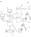
- the robot system 120 includes robots 12A and 12B, control devices 14A, 14B and 14C, a teaching device 16, a host controller 18, a mode switching device 20, peripheral devices 122, and a communication network 124.
- Peripheral devices 122 are, for example, belt conveyors, automatic guided vehicles (AGV), etc., and are arranged around the robots 12A and 12B to assist the robots 12A and 12B in their work.
- AGV automatic guided vehicles
- the controllers 14A, 14B, and 14C control the operations of the robot 12A, the robot 12B, and the peripheral device 122, respectively.
- the communication network 124 is, for example, a LAN such as an intranet, or the Internet, and connects the control devices 14A, 14B and 14C and the host controller 18 so as to be able to communicate with each other.
- host controller 18 is installed in a first building, while robots 12A and 12B, controllers 14A, 14B and 14C, teaching device 16, mode switching device 20, and peripheral device 122 are installed in the first building. It is installed in a second building (that is, a production line) that is separate from the first building.
- the host controller 18 gives commands to the control devices 14A, 14B and 14C through the communication network 124 according to a pre-determined production management scheme, and individually operates the robot 12A, the robot 12B, and the peripheral equipment 122, thereby get the job done.
- Each of the controllers 14A, 14B and 14C, the teaching device 16, the host controller 18, and the mode switching device 20 constitutes a tool having a function FC.
- the device 110 described above (that is, the image generation unit 112, the tool switching unit 114, the input reception unit 116, and the operation mode setting unit 118) is controlled by any one of the control devices 14A, 14B and 14C, the teaching device 16, and the host controller 18.
- the controller 14A, 14B or 14C, the teaching device 16, or the processor 40, 60 or 80 of the host controller 18 functions as the device 110.
- FIG. 1 the controller 14A, 14B or 14C, the teaching device 16, or the processor 40, 60 or 80 of the host controller 18 functions as the device 110.
- the control devices 14A and 14B each select the operation mode OM selected by the function FC of the mode switching device 20 (that is, "T1" (teaching mode OM1), "T2" (operation confirmation mode OM2), or In “AUTO” (automatic operation mode OM3)), the robots 12A and 12B are operated respectively.
- the operator can collectively select the operation modes OM of the robots 12A and 12B by the mode switching device 20 in which the function FC is enabled.
- the controller 14C may be omitted from the robot system 120, and the host controller 18 may directly give commands to the peripheral device 122 to control the peripheral device 122.
- the tool switching unit 114 when a plurality of tools 14 (14A, 14B, 14C), 16, 18, 20 each having a function FC are connected to the device 110 at the same time, the tool switching unit 114
- the tool's function FC may be temporarily disabled.
- the device 110 is mounted on the control device 14A, and the control devices 14B and 14C, the teaching device 16, and the host controller 18 are connected to the control device 14A.
- the processor 40 of the controller 14A outputs a signal SC_B indicating that the controller 14B is connected, a signal SC_C that indicates that the controller 14C is connected, and a signal S that indicates that the teaching device 16 is connected.
- T and a signal SH indicating that the host controller 18 is connected are obtained from the control devices 14B and 14C, the teaching device 16, and the host controller 18, respectively.
- the processor 40 of the controller 14A determines that the controllers 14B and 14C, the teaching device 16, and the host controller 18 simultaneously send signals to the controller 14A (that is, the device 110). You can recognize that you are connected. At this time, the processor 40 of the control device 14A functions as the tool switching section 114 and temporarily disables the function FC of the control devices 14B and 14C, the teaching device 16, and the host controller 18.
- FIG. 1 the processor 40 of the controller 14A determines that the controllers 14B and 14C, the teaching device 16, and the host controller 18 simultaneously send signals to the controller 14A (that is, the device 110). You can recognize that you are connected. At this time, the processor 40 of the control device 14A functions as the tool switching section 114 and temporarily disables the function FC of the control devices 14B and 14C, the teaching device 16, and the host controller 18.
- the operator is prohibited from operating the control device 14B or 14C, the teaching device 16, or the input device 46, 66 or 86 of the host controller 18 to select the operation mode OM of the robots 12A and 12B.
- the teaching device 16, or the host controller 18 may generate a warning signal indicating that the is disabled.
- control device 14A After that, the operator operates the input device 46 of the control device 14A to switch the tool for enabling the function FC through the tool switching image data 212 displayed in the image data 210 of FIG. Input IPs for switching to 14C, teaching device 16, or host controller 18 are provided to control device 14A.
- the processor 40 of the control device 14A functions as the tool switching unit 114 and selects the tool for enabling the function FC according to the signal SIP of the input IPs. Or switch to host controller 18 (i.e. second tool) and operator can select operation mode OM of robots 12A and 12B using function FC of said second tool 14A, 14B, 14C, 16 or 18 becomes.
- the mode switching device 20 given the highest priority is connected to the control device 14A.
- the processor 40 of the control device 14A may automatically switch the tool enabling the function FC to the mode switching device 20 having the highest priority.
- mode switching device 20 when mode switching device 20 is simultaneously connected to controller 14A in addition to controllers 14B and 14C, teach device 16, and host controller 18, processor 40 of controller 14A may , 14C, teaching device 16, host controller 18, and mode switching device 20 may be temporarily disabled.
- the tool switching unit 114 switches the function FC of the plurality of tools. is temporarily disabled. According to this configuration, it is possible to reliably prevent the operation mode OM from being selected with a plurality of tools 14 (14A, 14B, 14C), 16, 18, 20, thereby ensuring operator safety. .
- control device 14 (14A, 14B, 14C), the teaching device 16, the host controller 18, and the mode switching device 20, which are physical devices, are exemplified as tools having the function FC.
- any type of equipment may be connected to the robot system 10 or 120 (that is, the device 110) as a tool having the function FC.
- a tool with a functional FC is not limited to physical equipment, and may be software.
- another computer 150 (not shown) is connected to the controller 14, and multiple tools A and B as software are installed in the computer 150.
- Each of these tools A and B is configured to be able to execute the function FC on software.
- the operator can operate the input device (keyboard, etc.) of the computer 150 to activate the tool A or B on the computer 150, and use the function FC of the tool A or B to select the operation mode OM. ing.
- the tool switching unit 114 switches the tool whose function FC is valid among the control device 14, the teaching device 16, the host controller 18, the mode switching device 20, the tool A, and the tool B.
- the processor 60 of the teaching device 16 generates image data 210 shown in FIG. ' (control device 14), 'teaching device' (teaching device 16), 'host controller' (host controller 18), 'mode switching device' (mode switching device 20), 'tool A' and 'tool B'. can be displayed explicitly.
- a tool having a function FC is not limited to physical equipment, and may be configured from software.
- the teaching device 16 performs the function of teaching the motion of the robot 12 (or the robots 12A and 12B) has been described.
- the robot teaching function is not limited to this, and may be implemented in the control device 14 (or the control device 14A, 14B or 14C), for example.
- two or more teaching devices 16, upper controllers 18, or mode switching devices 20 may be connected to the control device 14.
- the input reception unit 116 and the image generation unit 112 can be omitted from the device 110 .
- the processor 40 without accepting input IPs from the operator, according to the priority, The tools that enable feature FC can be switched between a plurality of tools 14 (14A, 14B, 14C), 16, 18, 20.
- FIG. 1
- the device 110 that is, the image generation unit 112, the tool switching unit 114, the input reception unit 116, and the operation mode setting unit 118
- the functions of the device 110 may be implemented in the control device 14 or the host controller 18, for example.
- the processor 40 or 80 of the controller 14 or higher controller 18 functions as the device 110 .
- the processor 40 continues the optional operation mode OM4 and instructs the teaching device 16'.
- the robot 12 may be caused to perform a jog operation, a trial operation, or an automatic operation in accordance with a teaching command CMt, an operation confirmation command CMv, or an automatic operation start command CMa from.
- the processor 40 may enable the functional FC of the connected tool 16, 18 or 20. good.
- the teaching device 16 with the function FC is connected to the control device 14 during the optional operation mode OM4.
- the processor 40 of the control device 14 acquires the signal ST indicating that the teaching device 16 has been connected, functions as the tool switching section 114, and switches the function FC of the teaching device 16 according to the signal ST . is valid. Accordingly, the operator can select the operation mode OM of the robot 12 by operating the teaching device 16 using the function FC. It should be noted that if a plurality of tools 16, 18 and 20, each given a priority as described above, are connected to controller 14 during optional operation mode OM4, processor 40 will determine which tool 20 has the highest priority. Function FC may be enabled.
- processor 40 of controller 14 may automatically switch operation mode OM from teaching mode OM1, operation confirmation mode OM2, or automatic operation mode OM3 to optional operation mode OM4.
- the operator may apply an external force F to any part of the robot 12 (for example, the end effector 32).
- the processor 40 of the control device 14 obtains detection data of the external force F detected by the force sensor 36, and obtains the magnitude and direction of the external force F based on the detection data.
- the processor 40 operates the robot 12 according to the detected external force F to move the end effector 32 in the direction of the applied external force F (so-called direct teaching function DT).
- the robot 12 moves the end effector 32 in the direction of the external force F applied by the operator, thereby performing work in cooperation with the operator.
- the processor 40, 60 or 80 When the processor 40, 60 or 80 acquires the information IDr identifying the robot 12 as a collaborative robot, the processor 40, 60 or 80 functions as the operation mode setting unit 118 to set the predetermined operation mode instead of the arbitrary operation mode OM4 described above.
- OM may be set and fixed.
- the processor 40, 60 or 80 may set the direct teach mode OM5 according to the information IDr.
- This direct teaching mode OM5 is an operation mode OM that causes the processor 40 of the control device 14 to perform the above-described direct teaching function DT. Therefore, the operator can move the robot 12 in any direction by applying an external force F to the robot 12 in the direct teaching mode OM5.
- the processor 40, 60 or 80 acquires the signal SR from the control device 14 and functions as the operation mode setting unit 118. Then, a direct teach mode setting command CM5 is given to the controller 14 according to the information IDr attached to the signal SR .
- the processor 40 of the control device 14 receives the direct teach mode setting command CM5, it sets the operation mode OM of the robot 12 to the direct teach mode OM5 and fixes the operation mode OM of the robot 12 to the direct teach mode OM5.
- the processor 40 becomes ready to execute the direct teaching function DT.
- the processor 40, 60 or 80 recognizes that the tool 20 given the highest priority is connected to the device 110 during the direct teach mode OM5, the function FC of the tool 20 is is enabled, and the operation mode OM can be switched to the teaching mode OM1, the operation confirmation mode OM2, or the automatic operation mode OM3 by the function FC.
- the processor 40 of the controller 14 may automatically switch the operation mode OM from the teaching mode OM1, the operation confirmation mode OM2, or the automatic operation mode OM3 to the direct teaching mode OM5.
- the functions of the device 110 are implemented in the control device 14 and the tools 16, 18 and 20 having the function FC are not connected to the control device 14.
- the processor 40 of the control device 14 functions as the operation mode setting unit 118 to set the above-described direct teaching mode OM5. good too.
- the processor 40 changes the operation mode OM from the direct teach mode OM5 to an arbitrary operation mode. It may be automatically switched to mode OM4. In this case, the processor 40 causes the robot 12 to perform a jog operation, a trial operation, or an automatic operation in accordance with the teaching command CMt, the operation confirmation command CMv, or the automatic operation start command CMa from the teaching device 16' as the arbitrary operation mode OM4. may be executed.
- the operation mode OM is not limited to the teaching mode OM1, operation confirmation mode OM2, automatic operation mode OM3, arbitrary operation mode OM4, and direct teaching mode OM5 described above.
- the operation mode OM includes a high-speed operation mode in which the robot 12 is operated at a speed higher than the normal speed, and a high-precision operation mode in which the robot 12 is operated at a speed lower than the normal speed to increase the positioning accuracy of the teaching point TP (or the movement path MP).
- Any operation mode may be included, such as an operation mode, an energy-saving operation mode that reduces the power consumption of the robot 12, or the like.
- the robot 12 is not limited to a vertical multi-joint robot, and may be any type of robot such as a horizontal multi-joint robot or a parallel sync robot.
- a vertical multi-joint robot any type of robot such as a horizontal multi-joint robot or a parallel sync robot.
- robot system 12 robot 14 control device 16 teaching device 18 host controller 20 mode switching device 40, 60, 80 processor 102 physical switch 110 device 112 image generation unit 114 tool switching unit 116 input reception unit 118 operation mode setting unit
Abstract
例えば、ロボットの動作モードを選択する機能を有するロボットシステムを構築又は改変するときに、該機能を有効とする機器を変更したい場合がある。従来、このように機能を有効とする機器を変更するために、ソフトウェアの追加又は設定変更等が必要となり、その結果、ロボットシステムの構築又は改変等に掛かる作業が煩雑化していた。 ロボット12の動作モードを選択する機能を有する機器14,16,18,20を切り換える装置110は、該機能を有効とする機器14,16,18,20を、第1のツール14,16,18から第2のツール20へ切り換える機器切換部114を備える。
Description
本開示は、動作モードを選択する機能を有するツールを切り換える装置、教示装置、制御装置、ロボットシステム、及び方法に関する。
ロボットの動作モードを切り換える機能を有するツールが知られている(例えば、特許文献1)。
例えば、ロボットの動作モードを選択する機能を実行するツールを備えたロボットシステムを構築又は改変するときに、該機能を有効とするツールを変更したい場合がある。従来、このように機能を有効とするツールを変更するために、ソフトウェアの追加又は設定変更等が必要となり、その結果、ロボットシステムの構築又は改変等に掛かる作業が煩雑化していた。
本開示の一態様において、ロボットの動作モードを選択する機能を有するツールを切り換える装置は、機能を有効とするツールを、第1のツールから第2のツールに切り換えるツール切換部を備える。
本開示の他の態様においてロボットの動作モードを選択する機能を有するツールを切り換える方法は、プロセッサが、機能を有効とするツールを、第1のツールから第2のツールに切り換える。
本開示の他の態様においてロボットの動作モードを選択する機能を有するツールを切り換える方法は、プロセッサが、機能を有効とするツールを、第1のツールから第2のツールに切り換える。
本開示によれば、オペレータは、ソフトウェアの追加又は設定変更することなく、動作モードを選択する機能を有効とするツールを簡単に切り換ることができる。その結果、ロボットシステムの構築又は改変等に掛かる作業を簡単化できる。
以下、本開示の実施の形態を図面に基づいて詳細に説明する。なお、以下に説明する種々の実施形態において、同様の要素には同じ符号を付し、重複する説明を省略する。まず、図1及び図2を参照して、一実施形態に係るロボットシステム10について説明する。ロボットシステム10は、ロボット12、制御装置14、教示装置16、上位コントローラ18、及びモード切換装置20を備える。
本実施形態においては、ロボット12は、垂直多関節ロボットであって、ロボットベース22、旋回胴24、下腕部26、上腕部28、手首部30、及びエンドエフェクタ32を有する。ロボットベース22は、作業セルの床、又は無人搬送車(AGV)の上に固定される。旋回胴24は、鉛直軸周りに回動可能となるようにロボットベース22に設けられている。下腕部26は、水平軸周りに回動可能となるように旋回胴24に設けられ、上腕部28は、下腕部26の先端部に回動可能に設けられている。手首部30は、上腕部28の先端部に、互いに直交する2つの軸周りに回動可能に設けられている。
エンドエフェクタ32は、手首部30の先端部(いわゆる、手首フランジ)に着脱可能に取り付けられる。エンドエフェクタ32は、ロボットハンド、溶接トーチ、又はレーザ加工ヘッド等であって、ワークに対して所定の作業(ワークハンドリング、溶接、又はレーザ加工等)を行う。
ロボットベース22、旋回胴24、下腕部26、上腕部28、及び手首部30には、複数のサーボモータ34(図2)がそれぞれ設けられている。サーボモータ34は、制御装置14からの指令に応じて、ロボット12の各可動コンポーネント(すなわち、旋回胴24、下腕部26、上腕部28、及び手首部30)を駆動軸周りにそれぞれ回動させる。こうして、ロボット12は、制御装置14からの指令に応じて動作し、エンドエフェクタ32を任意の目的位置へ移動させる。
制御装置14は、ロボット12の動作を制御する。具体的には、制御装置14は、プロセッサ40、メモリ42、I/Oインターフェース44、入力装置46、及び表示装置48を有するコンピュータである。プロセッサ40は、CPU又はGPU等を有し、メモリ42、I/Oインターフェース44、入力装置46、及び表示装置48とバス50を介して通信可能に接続され、これらコンポーネントと通信しつつ、ロボット制御機能を実現するための演算処理を行う。
メモリ42は、RAM又はROM等を有し、各種データを一時的又は恒久的に記憶する。I/Oインターフェース44は、例えば、イーサネット(登録商標)ポート、USBポート、光ファイバコネクタ、又はHDMI(登録商標)端子を有し、プロセッサ40からの指令の下、外部機器との間でデータを有線又は無線で通信する。
入力装置46は、押しボタン、キーボード、マウス、又はタッチパネル等を有し、オペレータからの入力データを受け付ける。表示装置48は、液晶ディスプレイ又は有機ELディスプレイ等を有し、プロセッサ40からの指令の下、各種データを視認可能に表示する。なお、入力装置46及び表示装置48は、制御装置14の筐体に一体に組み込まれてもよいし、又は、制御装置14の筐体とは別体として該筐体に外付けされてもよい。
教示装置16は、ロボット12に所定の動作を教示する。具体的には、教示装置16は、例えば、教示ペンダント又はタブレット型端末装置等の携帯型コンピュータであって、プロセッサ60、メモリ62、I/Oインターフェース64、入力装置66、及び表示装置68を有する。なお、プロセッサ60、メモリ62、I/Oインターフェース64、入力装置66、及び表示装置68の構成は、上述のプロセッサ40、メモリ42、I/Oインターフェース44、入力装置46、及び表示装置48と同様であるので、重複する説明を省略する。
入力装置66及び表示装置68は、図1に示すように、教示装置16の筐体16aに一体に組み込まれている。入力装置66は、緊急停止ボタン66aを含む。緊急停止ボタン66aは、ロボット12を緊急停止させるためのものである。プロセッサ60は、メモリ62、I/Oインターフェース64、入力装置66、及び表示装置68とバス70を介して通信可能に接続され、これらコンポーネントと通信しつつ、教示機能を実現するための演算処理を行う。
教示装置16のプロセッサ60は、入力装置66への入力データに応じて、制御装置14を介してロボット12のサーボモータ34へ教示指令CMtを送り、該教示指令CMtに従って、該ロボット12をジョグ動作させることができるように構成されている。オペレータは、入力装置66を操作することでロボット12に所定の動作を教示し、プロセッサ60は、教示された該所定の動作をロボット12に実行させる動作プログラムPGを生成する。
上位コントローラ18は、制御装置14に指令を与えて該制御装置14を制御する。具体的には、上位コントローラ18は、例えば、プログラマブルロジックコントローラ(PLC)、又はデスクトップ型PC等のコンピュータであって、プロセッサ80、メモリ82、I/Oインターフェース84、入力装置86、及び表示装置88を有する。なお、プロセッサ80、メモリ82、I/Oインターフェース84、入力装置86、及び表示装置88の構成は、上述のプロセッサ40、メモリ42、I/Oインターフェース44、入力装置46、及び表示装置48と同様であるので、重複する説明を省略する。
プロセッサ80は、メモリ82、I/Oインターフェース84、入力装置86、及び表示装置88とバス90を介して通信可能に接続され、これらコンポーネントと通信しつつ、上位制御機能を実現するための演算処理を行う。例えば、プロセッサ80は、予め策定された生産管理スキームに従って、制御装置14へ指令を送り、該制御装置14の制御の下でロボット12を動作させることで、所定の作業を遂行する。
モード切換装置20は、制御装置14がロボット12を動作させる複数の動作モードOMのうちの1つを選択する機能FCを有する。図3に、モード切換装置20の一例を示す。モード切換装置20は、筐体100、物理スイッチ102、緊急停止ボタン104、プログラム実行ボタン108、及び物理キー106を有する。筐体100は、中空であって、その内部にモード切換装置20の機能を実現する電子部品(LSI等)を収容する。物理スイッチ102は、ロボット12の複数の動作モードOMのうちの1つを選択するためのものであって、筐体100の外部に露出するように該筐体100に回転可能に設けられている。
本実施形態においては、動作モードOMは、教示モードOM1、動作確認モードOM2、及び自動運転モードOM3を含む。教示モードOM1は、オペレータが教示装置16を用いてロボット12に所定の動作を教示することで、ロボット12の動作プログラムPGを作成する動作モードOMである。この教示モードOM1の間、オペレータは、教示装置16の入力装置66を操作することで制御装置14に教示指令CMtを与え、該教示指令CMtに従って、制御装置14は、ロボット12をジョグ動作させる。
オペレータは、ロボット12をジョグ動作させることで、該ロボット12に、ワークに対する作業を実行するときにエンドエフェクタ(又は、TCP)を位置決めする複数の教示点TP、及び該複数の教示点TPによって画定される、エンドエフェクタ(又は、TCP)の移動経路MPを教示する。こうして、オペレータは、この教示モードOM1において、ワークに対する作業を実行するための所定の動作をロボット12に教示する。
より具体的には、教示モードOM1においては、オペレータは、ロボット12に所定の動作を教示するために、該ロボット12を第1の速度V1で動作させる。制御装置14のプロセッサ40は、教示指令CMtに従ってロボット12を動作させるとき、該ロボット12(例えば、エンドエフェクタ32)の移動速度を、第1の速度V1以下に制限する。例えば、第1の速度V1は、V1=250[mm/sec]に設定される。
一方、動作確認モードOM2は、教示モードOM1で教示した所定の動作を確認するために、ロボット12に該所定の動作を試行させる動作モードOMである。具体的には、オペレータは、上述の教示モードOM1における教示の途中で生成された未完の動作プログラムPG’を試験的にロボット12に実行させることで、該ロボット12に教示した動作(つまり、動作プログラムPG’の適否)を確認する。
オペレータは、この動作確認モードOM2において、教示装置16の入力装置66を操作することで制御装置14に動作確認指令CMvを与え、該動作確認指令CMvに従って、制御装置14は、ロボット12に教示した所定の動作の確認のために、該ロボット12を、この時点で作成された動作プログラムPG’に従って、第1の速度V1よりも速い第2の速度V2(>V1)で動作させる。
ここで、教示モードOM1では、上述のようにロボット12(エンドエフェクタ32)の移動速度が制限されるので、目的とするロボット12の移動軌跡、及び実行する作業のサイクルタイムを確認することができない。そこで、動作確認モードOM2では、ロボット12に教示した動作(具体的には、動作プログラムPG’に従ったロボット12の動作)の確認のために、プロセッサ40は、動作確認指令CMvに従って、より高速の第2の速度V2でロボット12を動作させる。
第2の速度V2は、例えば、動作プログラムPG’に規定された速度である。オペレータは、動作確認モードOM2で試行したロボット12の動作を確認し、再度、教示モードOM1を実行し、動作プログラムPG’に規定されている教示点TP(又は移動経路MP)等を追加又は修正する。
このような教示の結果、プロセッサ60は、ワークに対する作業を実行するための正式な動作プログラムPGを生成し、生成した該動作プログラムPGを、制御装置14に提供する。動作プログラムPGには、教示された教示点TP及び移動経路MPとともに、ロボット12の速度V3等の動作条件が規定されている。
なお、制御装置14のプロセッサ40が教示モードOM1及び動作確認モードOM2でロボット12を動作させている間は、教示装置16以外のツール(つまり、制御装置14、上位コントローラ18、モード切換装置20)の入力装置(入力装置46、66、86)から動作プログラムPG(又はPG’)の実行を指令することが禁止される。
自動運転モードOM3は、例えば、作業セル内でロボット12にワークに対する実際の作業を実行させるために、動作プログラムPGに従ってロボット12を自動で動作させる動作モードOMである。本実施形態においては、オペレータは、モード切換装置20のプログラム実行ボタン108、又は上位コントローラ18の入力装置86を操作することで、制御装置14に自動運転開始指令CMaを与える。
該自動運転開始指令CMaに応じて、制御装置14のプロセッサ40は、自動運転モードOM3を開始し、動作プログラムPGに従ってロボット12を、動作プログラムPGに規定されている速度V3で、自動で動作させる。この速度V3は、上述の速度V2以上(V3≧V2)となり得る。その一方で、教示装置16の入力装置66から自動運転開始指令CMaを制御装置14へ送信することが禁止される。また、自動運転モードOM3の間は、教示装置16の入力装置66から制御装置14へ教示指令CMt及び動作確認指令CMvを送信することも禁止される。
以上のような通信を行うために、制御装置14のI/Oインターフェース44は、ロボット12の各サーボモータ34、教示装置16のI/Oインターフェース64、上位コントローラ18のI/Oインターフェース84、及び、モード切換装置20(具体的には、物理スイッチ102、緊急停止ボタン104、及びプログラム実行ボタン108)と、有線又は無線で通信可能に接続されている。
再度、図3を参照して、物理スイッチ102は、上述した教示モードOM1、動作確認モードOM2、及び自動運転モードOM3のうちの1つを選択する。本実施形態においては、筐体100に、「AUTO」、「T1」、及び「T2」が表示されており、物理スイッチ102は、筐体100に対して回転することで、これら「AUTO」、「T1」、又は「T2」を選択できるようになっている。
ここで、「AUTO」は、自動運転モードOM3に対応し、「T1」は、教示モードOM1に対応し、「T2」は、動作確認モードOM2に対応している。オペレータは、物理スイッチ102を手動で回転させることで、制御装置14に実行させる運転モードOMを、「AUTO」(自動運転モードOM3)、「T1」(教示モードOM1)、及び「T2」(動作確認モードOM2)の中から選択できるようになっている。なお、図3は、物理スイッチ102によって「AUTO」(自動運転モードOM3)が選択されている状態を示している。
オペレータが物理スイッチ102によって「T1」(教示モードOM1)を選択すると、モード切換装置20は、教示モード選択指令CM1を制御装置14に送信し、制御装置14が実行する動作モードOMを、教示モードOM1に移行する。その結果、オペレータは、教示装置16を用いて、教示モードOM1として制御装置14を介してロボット12を第1の速度V1で動作させ、ロボット12に動作を教示することが可能となる。
また、オペレータが物理スイッチ102によって「T2」(動作確認モードOM2)を選択すると、モード切換装置20は、動作確認モード選択指令CM2を制御装置14に送信し、制御装置14が実行する動作モードOMを、動作確認モードOM2に移行する。その結果、オペレータは、教示装置16を用いて、動作確認モードOM2として制御装置14を介してロボット12を第2の速度V2で動作させ、ロボット12に教示した動作を確認すること(例えば、動作プログラムPG’の動作確認)が可能となる。
一方、オペレータが物理スイッチ102によって「AUTO」(自動運転モードOM3)を選択すると、モード切換装置20は、自動運転モード選択指令CM3を制御装置14に送信し、制御装置14が実行する動作モードOMを、自動運転モードOM3に移行する。その結果、オペレータは、モード切換装置20のプログラム実行ボタン108、又は上位コントローラ18を操作して、動作プログラムPGに従ってロボット12を自動運転させることが可能となる。
物理キー106は、物理スイッチ102に形成された鍵穴102aに挿抜可能であって、該物理キー106を鍵穴102aに挿入すると、物理スイッチ102が回転可能になり、これにより、オペレータは、該物理スイッチ102を操作可能になる。その一方で、物理キー106が鍵穴102aから抜去されると、物理スイッチ102の回転が規制され、該物理スイッチ102が操作不能となる。
プログラム実行ボタン108は、制御装置14に自動運転モードOM3を開始させることができる。具体的には、オペレータは、物理スイッチ102によって「AUTO」を選択した状態で、プログラム実行ボタン108を操作する。そうすると、モード切換装置20は、自動運転モード選択指令CM3に続いて、自動運転開始指令CMaを制御装置14へ送信する。
制御装置14のプロセッサ40は、自動運転モード選択指令CM3に応じて、動作モードOMを自動運転モードOM3に移行する。これにより、プロセッサ40は、自動運転開始指令CMaを受け付け可能な状態となる一方、教示指令CMt及び動作確認指令CMvの受け付けを禁止する。自動運転モードOM3への移行後に自動運転開始指令CMaを受け付けると、プロセッサ40は、上述のように動作プログラムPGに従ってロボット12を自動運転させる。
緊急停止ボタン104は、ロボット12を緊急停止させるためのものである。例えば、制御装置14のプロセッサ40が、自動運転モードOM3でロボット12を自動運転しているとき(又は、動作確認モードOM2で動作プログラムPG’に従ってロボット12を動作させているとき)に、オペレータが緊急停止ボタン104を押すと、モード切換装置20は、緊急停止指令CMsを制御装置14に与える。
該緊急停止指令CMsに応じて、制御装置14は、例えば、各サーボモータ34への指令(電流指令)を停止するか、又は、各サーボモータ34の回転シャフトを制動するブレーキ機構を作動させることで、ロボット12を緊急停止させる。上述のように、モード切換装置20は、制御装置14によってロボット12を動作させる動作モードOM(すなわち、教示モードOM1、動作確認モードOM2、又は自動運転モードOM3)を選択する機能FCを有している。
教示装置16は、モード切換装置20と同様に、ロボット12の動作モードOMを選択する機能FCを有する。具体的には、教示装置16のプロセッサ60は、動作モードOMの選択を受け付けるためのモード選択画像データ200を生成し、表示装置68に表示する。図4に、モード選択画像データ200の一例を示す。
モード選択画像データ200は、オペレータに動作モードOMを選択可能とするためのグラフィカルユーザインターフェース(GUI)であって、T1ボタン画像データ202、T2ボタン画像データ204、及びAUTOボタン画像データ206を含む。T1ボタン画像データ202、T2ボタン画像データ204、及びAUTOボタン画像データ206は、それぞれ、教示モードOM1、動作確認モードOM2、及び自動運転モードOM3に対応している。
オペレータは、教示装置16の入力装置66を操作することで、T1ボタン画像データ202、T2ボタン画像データ204、又はAUTOボタン画像データ206を画像上でクリックすることで、教示モードOM1、動作確認モードOM2、又は自動運転モードOM3を選択することができるようになっている。
具体的には、プロセッサ60は、入力装置66から、モード選択画像データ200においてT1ボタン画像データ202を選択する入力IPmを受け付けると、教示モード選択指令CM1を制御装置14に送信し、制御装置14が実行する動作モードOMを、教示モードOM1に移行する。
また、プロセッサ60は、入力装置66からT2ボタン画像データ204を選択する入力IPmを受け付けると、動作確認モード選択指令CM2を制御装置14に送信し、制御装置14が実行する動作モードOMを、動作確認モードOM2に移行する。一方、プロセッサ60は、入力装置66からAUTOボタン画像データ206を選択する入力IPmを受け付けると、自動運転モード選択指令CM3を制御装置14に送信し、制御装置14が実行する動作モードOMを、自動運転教示モードOM3に移行する。また、教示モードOM1、動作確認モードOM2、又は自動運転教示モードOM3の間に、オペレータが緊急停止ボタン66aを押すと、プロセッサ60は、緊急停止指令CMsを制御装置14に送信し、ロボット12の動作を緊急停止させる。
上位コントローラ18は、教示装置16と同様に、ロボット12の動作モードOMを選択する機能FCを有する。上位コントローラ18のプロセッサ80は、教示装置16と同様にモード選択画像データ200を生成し、表示装置88に表示する。プロセッサ80は、入力装置86から、T1ボタン画像データ202、T2ボタン画像データ204、又はAUTOボタン画像データ206を選択する入力IPmを受け付けると、教示モード選択指令CM1、動作確認モード選択指令CM2、又は自動運転モード選択指令CM3を制御装置14に送信し、制御装置14が実行する動作モードOMを、教示モードOM1、動作確認モードOM2、又は自動運転教示モードOM3に移行する。
また、本実施形態においては、制御装置14も、教示装置16と同様に、ロボット12の動作モードOMを選択する機能FCを有する。一例として、制御装置14の入力装置46は、上述の物理スイッチ102を含んでもよい。この場合、オペレータは、該物理スイッチ102を操作することで、「AUTO」(自動運転モードOM3)、「T1」(教示モードOM1)、又は「T2」(動作確認モードOM2)を選択し、これにより、制御装置14が実行する動作モードOMを、教示モードOM1、動作確認モードOM2、又は自動運転教示モードOM3に移行する。
他の例として、制御装置14のプロセッサ40は、教示装置16と同様にモード選択画像データ200を生成し、表示装置48に表示する。プロセッサ40は、入力装置46から、T1ボタン画像データ202、T2ボタン画像データ204、又はAUTOボタン画像データ206を選択する入力IPmを受け付けると、教示モード選択指令CM1、動作確認モード選択指令CM2、又は自動運転モード選択指令CM3を制御装置14に送信し、制御装置14が実行する動作モードOMを、教示モードOM1、動作確認モードOM2、又は自動運転教示モードOM3に移行する。
なお、制御装置14のプロセッサ40、教示装置16のプロセッサ60、又は上位コントローラ18のプロセッサ80は、モード選択画像データ200を表示装置48、68又は88に表示する前に、オペレータから、機能FCを使用可能とするためのデジタルキーDKの入力IPdを受け付けてもよい。
デジタルキーDKは、例えば、パスワード、又はオペレータの識別情報(社員番号等)であり得る。プロセッサ40、60又は80は、入力装置46、66又は86を通して入力IPdを受け付けたときに、モード選択画像データ200を表示装置48、68又は88に表示し、オペレータが動作モードOMを選択可能とする。この場合において、プロセッサ40、60又は80は、デジタルキーDKを入力するためのデジタルキー画像データ(図示せず)を生成し、モード選択画像データ200の前に表示装置48、68又は88に表示してもよい。
以上のように、本実施形態においては、制御装置14、教示装置16、上位コントローラ18、及びモード切換装置20の各々が、ロボット12の動作モードOM(教示モードOM1、動作確認モードOM2、又は自動運転教示モードOM3)を選択する機能FCを有している。したがって、制御装置14、教示装置16、上位コントローラ18、及びモード切換装置20は、それぞれ、動作モードOMを選択する機能FCを有するツール14、16、18及び20を構成する。
なお、図2に示すロボットシステム10は、ロボット12の周囲を取り囲む安全柵をさらに備えてもよい。オペレータが安全柵の内側にいる場合に、動作モードOMとして、教示モードOM1又は動作確認モードOM2を選択し、オペレータが安全柵の外側にいる場合に、動作モードOMとして自動運転モードOM3を選択し、安全柵内外で動作モードOMを切り分けて使うようにしてもよい。
ここで、機能FCを各々有する複数のツール14、16、18及び20がロボットシステム10に接続された場合、作業の安全性の観点から、1つのツール14、16、18又は20の機能FCのみを有効とする一方で、その他のツール14、16、18又は20の機能FCを無効とする必要があり得る。
本実施形態においては、教示装置16のプロセッサ60は、機能FCを有効とするツール14、16、18又は20を、これら複数のツール14、16、18及び20の間で切り換える。具体的には、プロセッサ60は、図5に示す画像データ210を生成し、表示装置68に表示する。このように、本実施形態においては、プロセッサ60は、画像データ210を生成する画像生成部112(図2)として機能する。
図5に示す例では、画像データ210は、ツール切換画像データ212、及び動作モード表示画像データ214を含む。ツール切換画像データ212は、機能FCを有効とするツールを、制御装置14、教示装置16、上位コントローラ18、及びモード切換装置20の間で切り換えるためのものである。
ツール切換画像データ212には、ロボットシステム10に接続されているツールとして、「制御装置」(制御装置14)、「教示装置」(教示装置16)、「上位コントローラ」(上位コントローラ18)、及び「モード切換装置」(モード切換装置20)が選択的に表示され、オペレータは、入力装置66を操作することによって、ツール切換画像データ212において、制御装置14、教示装置16、上位コントローラ18、又はモード切換装置20に切り換えることができるようになっている。
なお、プロセッサ60は、ロボットシステム10において互いに接続されたツール14、16、18又は20を識別する情報IDeを取得してもよい。例えば、図1に示すように、ロボットシステム10において、制御装置14、教示装置16、上位コントローラ18、及びモード切換装置20が接続されたとする。
この場合、教示装置16のプロセッサ60は、ロボットシステム10に制御装置14が接続されたことを示す信号SCと、教示装置16が接続されたことを示す信号STと、上位コントローラ18が接続されたことを示す信号SHと、モード切換装置20が接続されたことを示す信号SMとを、該制御装置14、該教示装置16、該上位コントローラ18、及び該モード切換装置20からそれぞれ取得する。
この場合において、信号SCは、制御装置14を識別する情報IDe1(例えば、識別番号)を付帯情報として含み、信号STは、教示装置16を識別する情報IDe2(例えば、識別番号)を付帯情報として含み、信号SHは、上位コントローラ18を識別する情報IDe3を付帯情報として含み、信号SMは、モード切換装置20を識別する情報IDe4を付帯情報として含んでもよい。
教示装置16のプロセッサ60は、取得した信号SC、ST、SM及びSMに付帯されている識別情報IDe1、IDe2、IDe3、IDe4によって識別されるツール(つまり、制御装置14、教示装置16、上位コントローラ18、及びモード切換装置20)を、ツール切換画像データ212に選択的に表示する。
動作モード表示画像データ214は、ツール切換画像データ212に表示されているツール(図5に示す例では、教示装置16)で選択可能な動作モードOM(図5に示す例では、「AUTO」:自動運転モードOM3、「T1」:教示モードOM1、及び「T2」:動作確認モードOM2)を表示する。
例えば、複数のツール14、16、18及び20で選択可能な動作モードOMのデータベースがメモリ62に予め格納されてもよい。この場合において、プロセッサ60は、ツール切換画像データ212に表示されているツール14、16、18又は20で選択可能な動作モードOMを該データベースから読み出し、動作モード表示画像データ214に表示してもよい。
代替的には、ツール14、16、18及び20で選択可能な動作モードOMの情報は、上述した信号SC、ST、SH及びSM(例えば、識別情報IDe1、IDe2、IDe3、IDe4)に含まれ、プロセッサ60は、選択可能な動作モードOMの情報を、該信号SC、ST、SH及びSMから取得してもよい。
例えば、オペレータが、入力装置66を操作して、ツール切換画像データ212においてモード切換装置20を指定する入力IPsをしたとする。この場合、プロセッサ60は、入力装置66から該入力IPsに応じた信号SIPを受け付け、該信号SIPに応じて、機能FCを有効とするツールを、モード切換装置20に切り換える。
より具体的には、プロセッサ60は、信号SIPに応じて、モード切換装置20の機能FCのみを有効とする一方、その他のツールである制御装置14、教示装置16及び上位コントローラ18の機能FCを無効とする指令CMfを、制御装置14に送信する。制御装置14のプロセッサ40は、該指令CMfを受けると、モード切換装置20の機能FCによって送信される教示モード選択指令CM1、動作確認モード選択指令CM2、又は自動運転モード選択指令CM3を受け付け可能となる。
その一方で、プロセッサ40は、制御装置14、教示装置16、及び上位コントローラ18の機能FCによって送信される教示モード選択指令CM1、動作確認モード選択指令CM2、又は自動運転モード選択指令CM3を拒絶する。こうして、ツール切換画像データ212で指定されたモード切換装置20の機能FCのみが有効となって、モード切換装置20で動作モードOMを選択可能になる一方、制御装置14、教示装置16及び上位コントローラ18の機能FCが無効となって、これら制御装置14、教示装置16及び上位コントローラ18で動作モードOMを選択できなくなる。
一方、オペレータが、ツール切換画像データ212において教示装置16(又は上位コントローラ18)を指定する入力IPsをしたとする。この場合、プロセッサ60は、入力装置66から該入力IPsに応じた信号SIPを受け付け、該信号SIPに応じて、機能FCを有効とするツールを、教示装置16(又は上位コントローラ18)に切り換える。そして、プロセッサ60(又は80)は、図4に示すモード選択画像データ200を生成して表示装置68(又は88)に表示し、該モード選択画像データ200を通して動作モードOMを選択する入力IPmを受け付け可能となる。
このように、本実施形態においては、プロセッサ40は、所定の信号SIPに応じて、機能FCを有効とするツールを、制御装置14、教示装置16、上位コントローラ18、及びモード切換装置20の間で切り換える。したがって、プロセッサ40は、機能FCを有効とするツールを、第1のツール(例えば、制御装置14、教示装置16、又は上位コントローラ18)から第2のツール(例えば、モード切換装置20)に切り換えるツール切換部114(図2)として機能する。
また、本実施形態においては、プロセッサ40は、入力装置66を介して、機能FCを有効とするツールを第2のツール(例えば、モード切換装置20)に切り換える入力IPsを受け付け、該入力IPsの信号SIPに応じて、機能FCを有効とするツールを、第1のツールから第2のツールに切り換えている。したがって、プロセッサ40は、入力IPsを受け付ける入力受付部116(図2)として機能する。
ここで、制御装置14、教示装置16、上位コントローラ18、及びモード切換装置20に、予め定められた優先順位が与えられる場合がある。例えば、産業用ロボットの安全規格上、モード切換装置20の機能FCを最優先すべき場合がある。この場合、モード切換装置20に最上位の優先順位が与えられることになる。
このような場合において、制御装置14、教示装置16、上位コントローラ18、及びモード切換装置20が互いに接続されると、教示装置16のプロセッサ60は、上述のように、接続を示す信号SC、ST、SH及びSMを、該制御装置14、該教示装置16、該上位コントローラ18、及び該モード切換装置20からそれぞれ取得する。
次いで、プロセッサ60は、モード切換装置20の接続を示す信号SMから、最上位の優先順位が付与されているモード切換装置20が接続されたことを認識する。なお、プロセッサ60は、制御装置14、教示装置16、及び上位コントローラ18が起動(つまり、電源ONに)される毎に、接続を示す信号SC、ST、SH及びSMを収集してもよい。
そして、プロセッサ60は、ツール切換部114として機能して、接続されている制御装置14、教示装置16、上位コントローラ18、及びモード切換装置20のうち、機能FCを有効とするツールを、優先順位が最上位であるモード切換装置20に自動で切り換える。このように、プロセッサ60は、優先順位が最上位であるモード切換装置20が接続されたことを示す信号SMを受け付けたときに、機能FCを有効とするツールを、該モード切換装置20に自動で切り換える。
他の例として、制御装置14に、教示装置16及び上位コントローラ18が接続されており、例えば教示装置16の機能FCが有効とされていたとする。この状態で、制御装置14に優先順位が最上位であるモード切換装置20が新たに接続された場合、プロセッサ60は、モード切換装置20の接続を示す信号SMを受け付け、ツール切換部114として機能して、機能FCを有効とするツールを、教示装置16からモード切換装置20に自動で切り換える。
なお、複数のツール14、16、18、20のうち、最上位の優先順位のみが、モード切換装置20に与えられてもよい。この場合において、優先順位が最上位であるモード切換装置20が制御装置14に接続されていない場合は、オペレータは、制御装置14、教示装置16又は上位コントローラ18を操作して、図5に示す画像データ210を通して、機能FCを有効とするツールを、制御装置14、教示装置16及び上位コントローラ18の間で任意に切り換えることができる。
代替的には、複数のツール14、16、18及び20の各々に、優先順位が付与されてもよい。例えば、優先順位1位がモード切換装置20に与えられ、優先順位2位が教示装置16に与えられ、優先順位3位が上位コントローラ18に与えられ、優先順位4位が制御装置14に与えられ得る。
この場合、プロセッサ40は、接続を示す信号SC、ST、SH及びSMを受け付けたときに、接続されているツール14、16、18及び20の中で、機能FCを有効とするツールを、優先順位に従って自動で切り換える。ツール14、16、18及び20に対して如何なる優先順位を与えるかは、オペレータによって任意に定められ得る。
なお、上述のように最上位の優先順位が与えられたモード切換装置20が制御装置14に接続されているとき(つまり、信号SMを受け付けたとき)に、オペレータが制御装置14、教示装置16又は上位コントローラ18を操作して、図5に示す画像データ210を通してモード切換装置20以外のツール(すなわち、制御装置14、教示装置16又は上位コントローラ18)を指定する入力IPsをした場合、プロセッサ60は、モード切換装置20以外のツールの機能FCを有効にできない旨を表す警告信号SALを生成してもよい。
例えば、プロセッサ60は、「モード切換装置以外のツールでは動作モードを選択する機能を使用できません」という画像データ又は音声データの警告信号SALを生成し、表示装置68、又は教示装置16に設けられたスピーカ(図示せず)を通して、出力してもよい。代替的には、プロセッサ60は、警告信号SALを生成する代わりに(又は、警告信号SALを生成するとともに)、上述の緊急停止指令CMsを制御装置14に送信し、ロボット12の動作を停止させてもよい。
以上のように、本実施形態においては、プロセッサ60が、画像生成部112、ツール切換部114、及び入力受付部116として機能して、ロボット12の動作モードOM(教示モードOM1、動作確認モードOM2、又は自動運転モードOM3)を選択する機能FCを有するツール14、16、18、20を切り換えている。
したがって、画像生成部112、ツール切換部114、及び入力受付部116は、ツール14、16、18、20を切り換える装置110(図2)を構成する。つまり、本実施形態においては、装置110(画像生成部112、ツール切換部114、及び入力受付部116)の機能が、教示装置16に実装され、該教示装置16のプロセッサ60が、装置110の機能を実行する。例えば、装置110は、プロセッサ60が実行するコンピュータプログラムにより実現される機能モジュールとして、教示装置16に実装される。
上述のように、本実施形態においては、ツール切換部114は、機能FCを有効とするツールを、第1のツール(例えば、制御装置14、教示装置16、又は上位コントローラ18)から第2のツール(例えば、モード切換装置20)に切り換えている。この構成によれば、例えばロボットシステム10を構築又は改変する場合において、オペレータは、ソフトウェアの追加又は設定変更することなく、動作モードOMを選択する機能FCを有効とするツール14、16、18、20を簡単に切り換えることができる。その結果、ロボットシステム10の構築又は改変等に掛かる作業を簡単化できる。
また、本実施形態においては、動作モードOMは、教示モードOM1、動作確認モードOM2、及び自動運転モードOM3を含む。この構成によれば、オペレータは、安全性に関連する教示モードOM1、動作確認モードOM2及び自動運転モードOM3を選択する機能FCを、ツール14、16、18及び20の間で切り換えることができるので、自身の安全性を確保しつつ、ロボット12の教示、動作確認、及び自動運転を実行できる。
また、本実施形態においては、ツール14、16、18、20は、ロボット12を制御する制御装置14と、該ロボット12を動作させて該ロボット12に所定の動作を教示する教示装置16と、制御装置14に指令を与える上位コントローラ18と、物理スイッチ102を有するモード切換装置20とを含む。この構成によれば、オペレータは、作業に応じて、機能FCを有効とするツールを、制御装置14、教示装置16、上位コントローラ18、及びモード切換装置20の間で任意に切り換えることができる。
また、本実施形態においては、入力受付部116は、機能FCを有効とするツール14、16、18、20を切り換える入力IPsを受け付けている。この構成によれば、オペレータは、機能FCを有効とするツール14、16、18又は20を任意に指定することができる。
また、本実施形態においては、入力IPsを受け付けるための画像データ210(図5)を生成する画像生成部112をさらに備え、入力受付部116は、画像データ210を通して入力IPsを受け付けている。この構成によれば、オペレータは、画像データ210を視認しつつ、機能FCを有効とするツール14、16、18又は20を簡単に指定できる。
また、本実施形態においては、ツール切換部114は、第2のツール(例えば、モード切換装置20)が装置110(つまり、教示装置16)に接続されたことを示す信号(例えば、信号SM)に応じて、機能FCを有効とするツールを、該第2のツールに切り換えている。この構成によれば、第2のツール(モード切換装置20)の接続時に、機能FCを有効とするツールを第2のツールに自動で切り換えることができる。
また、本実施形態においては、ツール切換部114は、装置110(すなわち、教示装置16)が起動されたときに(つまり、電源ON)、信号SC、ST、SH及びSMを取得している。この構成によれば、装置110の起動時に信号SC、ST、SH及びSMから第2のツール(例えば、モード切換装置20)の接続の有無を認識し、機能FCを有効とするツールを該第2のツールに自動で切り換えることができる。
また、本実施形態においては、複数のツール16、18及び20には、予め定められた優先順位が与えられ、ツール切換部114は、複数のツール16、18及び20のうち、優先順位が最上位であるツール(モード切換装置)20が装置110に接続されたことを示す信号SMを受け付けたときに、機能FCを有効とするツールを、優先順位が最上位であるツール20に自動で切り換えている。
この構成によれば、例えば安全規格の観点からモード切換装置20の機能FCを最優先すべき場合において、該モード切換装置20を制御装置14に接続したときに、機能FCを有効にするツールを、該モード切換装置20に自動で切り換えることができる。したがって、作業の安全性を確実に確保できる。
次に、図6を参照して、ロボットシステム10の他の機能について説明する。図6に示すロボットシステム10においては、ロボット12は、オペレータと協働で作業を実行可能な協働ロボットであって、力センサ36をさらに備える。力センサ36は、例えば、手首部30とエンドエフェクタ32との間、又は、ロボットベース22と作業セルの床との間に設けられ、ロボット12に加えられた外力Fを検出する。
一方、プロセッサ40は、検出された外力Fが所定の閾値Fthを超えた場合(F>Fth)にロボット12の動作を緊急停止させる。これにより、仮に、ロボット12の動作中に該ロボット12とオペレータとが接触したとしても、ロボット12を自動で緊急停止させ、オペレータの安全を確保できる。
このようなロボット12においては、オペレータが教示モードOM1、動作確認モードOM2、又は自動運転モードOM3を手動で選択せずに、これら動作モードOM1、OM2及びOM3のいずれかの動作をロボット12に直接実行させたとしても、オペレータの安全を確保でき得る。本実施形態においては、教示装置16のプロセッサ60は、ロボット12の接続を認識したときに、制御装置14が、教示モードOM1、動作確認モードOM2、及び自動運転モードOM3のいずれの動作も実行可能となる任意動作モードOM4を設定する。
具体的には、協働ロボットとしてのロボット12が制御装置14に接続されたとき、該制御装置14のプロセッサ40は、ロボット12が接続されたことを示す信号SRを取得する。この信号SRは、例えば、ロボット12を識別する情報IDr(例えば、ロボット12の識別番号)を、付帯情報として含んでもよい。
教示装置16のプロセッサ60は、制御装置14から信号SRを取得し、該信号SR(識別情報IDr)から、ロボット12が協働ロボットであることを認識できる。これに応じて、プロセッサ60は、任意動作モードOM4を設定する。具体的には、プロセッサ60は、任意動作モード設定指令CM4を制御装置14に送信する。
制御装置14のプロセッサ40は、任意動作モード設定指令CM4を受け付けると、ロボット12の動作モードOMを、任意動作モードOM4に設定する。この任意動作モードOM4においては、プロセッサ40は、上述の教示指令CMt、動作確認指令CMv、及び自動運転開始指令CMaのいずれも受け付け可能な状態となり、受け付けた教示指令CMt、動作確認指令CMv、又は自動運転開始指令CMaに応じて、教示モードOM1、動作確認モードOM2、及び自動運転モードOM3のいずれの動作もロボット12に実行させることができる状態となる。
この任意動作モードOM4においては、オペレータは、ツール14、16、18又は20の機能FCを使用して動作モードOMを手動で選択することなく、教示指令CMt、動作確認指令CMv、又は自動運転開始指令CMaを制御装置14に与え、与えた教示指令CMt、動作確認指令CMv、又は自動運転開始指令CMaに応じた動作をロボット12に実行させることができる。
例えば、オペレータが、任意動作モードOM4の間に、教示装置16の入力装置66を操作して、モード選択画像データ200(図4)で「T1」(教示モードOM1)を選択することなく(換言すれば、教示モード選択指令CM1を制御装置14に送信することなく)、ロボット12をジョグ動作させるための教示指令CMtを制御装置14に与えたとする。この場合、制御装置14のプロセッサ40は、受け付けた教示指令CMtに応じて、ロボット12をジョグ動作させる。
続いて、オペレータが、教示装置16の入力装置66を操作して、モード選択画像データ200で「T2」(動作確認モードOM2)を選択することなく(換言すれば、動作確認モード選択指令CM2を制御装置14に送信することなく)、未完の動作プログラムPG’の動作をロボット12に試行させるための動作確認指令CMvを制御装置14に与えたとする。この場合、制御装置14のプロセッサ40は、ロボット12のジョグ動作を終了し、受け付けた動作確認指令CMvに応じて、動作プログラムPG’の試行動作を開始する。
続いて、オペレータが、教示装置16の入力装置66を操作して、モード選択画像データ200で「AUTO」(自動運転モードOM3)を選択することなく(換言すれば、自動運転モード選択指令CM3を制御装置14に送信することなく)、自動運転開始指令CMaを制御装置14に与えたとする。この場合、制御装置14のプロセッサ40は、動作プログラムPG’の試行動作を終了し、受け付けた自動運転開始指令CMaに応じて、動作プログラムPGに従ってロボット12を自動運転させる。
このように、本実施形態においては、教示装置16のプロセッサ60は、ロボット12が装置110に接続されたことを示す信号SRを取得し、該信号SRに付帯されたロボット12(協働ロボット)を識別する情報IDrに応じて、制御装置14が、教示モードOM1、動作確認モードOM2、及び自動運転モードOM3のいずれの動作も実行可能となる任意動作モードOM4を設定する。
したがって、プロセッサ60は、任意動作モードOM4を設定する動作モード設定部118(図6)として機能する。この動作モード設定部118は、プロセッサ60が実行するコンピュータプログラム(例えば、ソフトウェア)により実現される機能モジュールとして、教示装置16に実装され得る。動作モード設定部118は、上述の画像生成部112、ツール切換部114、及び入力受付部116とともに、装置110を構成する。
なお、任意動作モードOM4を設定したとき、プロセッサ60は、図7の画像データ210に示すように、任意動作モードOM4を表す「任意動作モード」という画像データを、ツール切換画像データ212に表示してもよい。そして、プロセッサ60は、動作モード表示画像データ214において、このときに制御装置14のプロセッサ40がロボット12に実行させている動作モードOM(図7に示す例では、「T1」:教示モードOM1)を表示してもよい。
ここで、プロセッサ60は、任意動作モードOM4の間に、最上位の優先順位が与えられているツール20が装置110に接続されたことを認識したときに、該ツール20の機能FCを有効としてもよい。例えば、図6に示すロボットシステム10において、制御装置14が任意動作モードOM4を実行しているときに、最上位の優先順位が与えられたモード切換装置20が該制御装置14に接続されたとする。
この場合、教示装置16のプロセッサ60は、モード切換装置20の接続を示す信号SMを、制御装置14を通して取得し、これにより、装置110(つまり、教示装置16)にモード切換装置20が接続されたことを認識できる。そして、プロセッサ60は、任意動作モードOM4としてこの時点で実行していたロボット12の動作(例えば、ジョグ動作)を終了し、ツール切換部114として機能して、モード切換装置20の機能FCを有効とする。
これにより、オペレータは、モード切換装置20の物理スイッチ102を操作することで、動作モードOMを選択可能になる。そして、プロセッサ60は、ロボット12の動作モードOMを、任意動作モードOM4から、モード切換装置20によって選択された動作モードOM(例えば、自動運転モードOM3)に移行する。その結果、協働ロボットとしてのロボット12を、オペレータが手動で選択した教示モードOM1、動作確認モードOM2、又は自動運転モードOM3で動作させることができる。
以上のように、本実施形態においては、動作モード設定部118は、ロボット12を識別する情報IDrに応じて、任意動作モードOM4を設定する。この構成によれば、例えば、緊急停止可能なロボット12(協働ロボット)に、教示モードOM1、動作確認モードOM2、又は自動運転モードOM3のいずれの動作を任意に実行させることができる。これにより、オペレータの安全を確保しつつ、ロボット12の教示及び自動運転を任意に実行できる。
また、本実施形態においては、プロセッサ60は、任意動作モードOM4の間に最上位の優先順位が与えられているツール20が装置110に接続されたことを認識したときに、該ツール20の機能FCを有効としている。この構成によれば、緊急停止可能なロボット12に対しても、オペレータは、ツール20の機能FCを通して、実行する動作モードOMを任意に選択できる。これにより、オペレータの作業の安全性をさらに高めることができる。
なお、本実施形態においては、ロボット12が、協働ロボットである場合について述べた。しかしながら、ロボット12は、協働ロボットに限定されず、オペレータの安全性が確保できる如何なるタイプのロボットであってもよい。例えば、ロボット12は、寸法が比較的小型(例えば、オペレータよりも小型)であるロボット、又は、最大動作速度若しくは最大動作トルクが低く設定されているロボットであってもよい。
このような安全性の高いロボット12の場合、仮に、オペレータが近くにいる状態で該ロボット12が動作確認モードOM2又は自動運転モードOM3を実行したとしても、オペレータの安全を確保でき得る。したがって、この場合、教示装置16のプロセッサ60は、制御装置14から、このような安全性の高いロボット12の信号SR(例えば、識別情報IDr)を受け付けたとき、該信号SRに応じて、任意動作モードOM4を設定してもよい。
また、上述したような協働ロボット又は安全性の高いロボットの場合、図6に示すロボットシステム10は、オペレータの安全を確保するための安全柵自体が不要となるので、該安全柵を省略することがある。しかしながら、よりオペレータの安全を確保するために、安全柵を設けて、安全柵の内外でロボットの動作モードOMを切り分けるようにロボットシステム10を変更したい場合があり得る。このようなロボットシステムにおいて、最上位の優先順位が与えられているツール20が装置110に接続されたときに、プロセッサ60が該ツール20の機能FCを有効とすることで、オペレータは、ソフトウェアの追加又は設定変更することなく、ロボットシステム10の構築又は改変等に掛かる作業を簡単化できる。
次に、図8を参照して、他の実施形態に係るロボットシステム120について説明する。ロボットシステム120は、ロボット12A及び12B、制御装置14A、14B及び14C、教示装置16、上位コントローラ18、モード切換装置20、周辺機器122、並びに、通信ネットワーク124を備える。
ロボット12A及び12Bの構成は、上述のロボット12と同様であり、また、制御装置14A、14B及び14Cの構成は、上述の制御装置14と同様であるので、重複する説明を省略する。周辺機器122は、例えば、ベルトコンベア、又は無人搬送車(AGV)等であって、ロボット12A及び12Bの周囲に配置されて、該ロボット12A及び12Bの作業を補助する。
制御装置14A、14B及び14Cは、それぞれ、ロボット12A、ロボット12B、及び周辺機器122の動作を制御する。通信ネットワーク124は、例えば、イントラネット等のLAN、又はインターネットであって、制御装置14A、14B及び14C、並びに上位コントローラ18を、互いに通信可能に接続する。
例えば、上位コントローラ18は、第1の建物内に設置される一方、ロボット12A及び12B、制御装置14A、14B及び14C、教示装置16、モード切換装置20、並びに周辺機器122は、第1の建物とは別の第2の建物内(つまり、製造ライン)に設置される。
上位コントローラ18は、予め策定された生産管理スキームに従って、通信ネットワーク124を通して制御装置14A、14B及び14Cに指令を与え、ロボット12A、ロボット12B、及び周辺機器122を個々に動作させることによって、所定の作業を遂行する。制御装置14A、14B及び14C、教示装置16、上位コントローラ18、並びにモード切換装置20の各々は、機能FCを有するツールを構成する。
上述の装置110(つまり、画像生成部112、ツール切換部114、入力受付部116、動作モード設定部118)は、制御装置14A、14B及び14C、教示装置16、並びに上位コントローラ18のうちのいずれに実装されてもよい。この場合、制御装置14A、14B若しくは14C、教示装置16、又は上位コントローラ18のプロセッサ40、60又は80が、装置110として機能する。
例えば、装置110が制御装置14Aに実装され、該制御装置14Aのプロセッサ40が、ツール切換部114として機能して、機能FCを有効とするツールを、モード切換装置20に切り換えたとする。この場合、制御装置14A及び14Bは、それぞれ、モード切換装置20の機能FCによって選択されている動作モードOM(つまり、「T1」(教示モードOM1)、「T2」(動作確認モードOM2)、又は「AUTO」(自動運転モードOM3))で、ロボット12A及び12Bをそれぞれ動作させる。
すなわち、この場合、オペレータは、機能FCが有効となっているモード切換装置20によって、ロボット12A及び12Bの動作モードOMを一括で選択できる。なお、ロボットシステム120から制御装置14Cを省略し、上位コントローラ18が周辺機器122に直接的に指令を与えて、該周辺機器122を制御してもよい。
なお、上述の実施形態において、機能FCを各々有する複数のツール14(14A、14B、14C)、16、18、20が装置110に同時に接続された場合に、ツール切換部114は、該複数のツールの機能FCを一時的に無効にしてもよい。例えば、図8に示すロボットシステム120において、装置110が制御装置14Aに実装され、且つ、該制御装置14Aに、制御装置14B及び14C、教示装置16、並びに上位コントローラ18が接続されたとする。
制御装置14Aのプロセッサ40は、制御装置14Bが接続されたことを示す信号SC_Bと、制御装置14Cが接続されたことを示す信号SC_Cと、教示装置16が接続されたことを示す信号STと、上位コントローラ18が接続されたことを示す信号SHとを、該制御装置14B及び14C、該教示装置16、並びに該上位コントローラ18からそれぞれ取得する。
制御装置14Aのプロセッサ40は、これら信号SC_B、SC_C、ST及びSHから、制御装置14B及び14C、教示装置16、並びに上位コントローラ18が、制御装置14A(つまり、装置110)に同時に接続されたことを認識できる。このとき、制御装置14Aのプロセッサ40は、ツール切換部114として機能して、これら制御装置14B及び14C、教示装置16、並びに上位コントローラ18の機能FCを、一時的に無効にする。
その結果、オペレータは、制御装置14B若しくは14C、教示装置16、又は上位コントローラ18の入力装置46、66又は86を操作してロボット12A及び12Bの動作モードOMを選択することが禁止される。このとき、制御装置14Aのプロセッサ40は、制御装置14B若しくは14C、教示装置16、又は上位コントローラ18の入力装置46、66又は86を通して機能FCを使用するための入力IPmを受け付けたとき、機能FCが無効となっていることを示す警告信号を生成してもよい。
その後、オペレータは、制御装置14Aの入力装置46を操作して、図5の画像データ210に表示されているツール切換画像データ212を通して、機能FCを有効とするツールを、制御装置14A、14B若しくは14C、教示装置16、又は上位コントローラ18に切り換える入力IPsを制御装置14Aに与える。
そうすると、制御装置14Aのプロセッサ40は、ツール切換部114として機能して、入力IPsの信号SIPに応じて、機能FCを有効とするツールを、制御装置14A、14B若しくは14C、教示装置16、又は上位コントローラ18(つまり、第2のツール)に切り換え、オペレータは、該第2のツール14A、14B、14C、16又は18の機能FCを用いて、ロボット12A及び12Bの動作モードOMを選択可能となる。
なお、制御装置14B及び14C、教示装置16、並びに上位コントローラ18の機能FCを一時的に無効にしている間に、最上位の優先順位が与えられたモード切換装置20が制御装置14Aに接続されたことを示す信号SMを受け付けたとき、制御装置14Aのプロセッサ40は、機能FCを有効とするツールを、優先順位が最上位のモード切換装置20に自動で切り換えてもよい。
代替的には、制御装置14B及び14C、教示装置16、並びに上位コントローラ18に加えて、モード切換装置20が制御装置14Aに同時に接続されたときに、制御装置14Aのプロセッサ40は、制御装置14B及び14C、教示装置16、上位コントローラ18、並びにモード切換装置20の機能FCを一時的に無効にしてもよい。
以上のように、本実施形態においては、ツール切換部114は、ツール14(14A、14B、14C)、16、18、20が装置110に同時に接続された場合に、該複数のツールの機能FCを一時的に無効している。この構成によれば、複数のツール14(14A、14B、14C)、16、18、20で動作モードOMを選択することを確実に防止し、以って、オペレータの安全を確保することができる。
なお、上述の実施形態においては、機能FCを有するツールとして、物理的な機器である制御装置14(14A、14B、14C)、教示装置16、上位コントローラ18、モード切換装置20を例示した。しかしながら、これに限らず、機能FCを有するツールとして、如何なるタイプの機器がロボットシステム10又は120(つまり、装置110)に接続されてもよい。
また、機能FCを有するツールは、物理的な機器に限らず、ソフトウェアであってもよい。例えば、図1及び図2に示すロボットシステム10において、他のコンピュータ150(図示せず)が制御装置14に接続され、該コンピュータ150に、ソフトウェアとしての複数のツールA及びBがインストールされる。
これらツールA及びBの各々は、ソフトウェア上で機能FCを実行することができるように構成されている。オペレータは、コンピュータ150の入力装置(キーボード等)を操作して、ツールA又はBをコンピュータ150上で起動し、該ツールA又はBの機能FCを用いて、動作モードOMを選択できるようになっている。
この場合において、ツール切換部114は、機能FCを有効とするツールを、制御装置14、教示装置16、上位コントローラ18、モード切換装置20、ツールA、及びツールBの間で切り換える。例えば、装置110が教示装置16に実装されている場合において、教示装置16のプロセッサ60は、図5に示す画像データ210を生成し、該画像データ210のツール切換画像データ212において、「制御装置」(制御装置14)、「教示装置」(教示装置16)、「上位コントローラ」(上位コントローラ18)、「モード切換装置」(モード切換装置20)、「ツールA」及び「ツールB」を選択的に表示してもよい。
そして、オペレータは、入力装置66を操作することによって、ツール切換画像データ212において、教示装置16、上位コントローラ18、モード切換装置20、ツールA、又はツールBに切り換えることができるように構成されてもよい。このように、機能FCを有するツールは、物理的な機器に限らず、ソフトウェアから構成されてもよい。
なお、上述の実施形態においては、教示装置16が、ロボット12(又は、ロボット12A及び12B)の動作を教示する機能を実行する場合について述べた。しかしながら、これに限らず、ロボット教示機能が、例えば、制御装置14(又は、制御装置14A、14B又は14C)に実装されてもよい。
また、上述の実施形態において、2つ以上の教示装置16、上位コントローラ18、又はモード切換装置20が、制御装置14に接続されてもよい。また、装置110から、入力受付部116及び画像生成部112を省略することもできる。例えば、上述したようにツール14(14A、14B、14C)、16、18、20に優先順位が付与されている場合、プロセッサ40は、オペレータからの入力IPsを受け付けることなく、該優先順位に従って、機能FCを有効とするツールを、複数のツール14(14A、14B、14C)、16、18、20の間で切り換えることができる。
なお、上述のロボットシステム10においては、装置110(つまり、画像生成部112、ツール切換部114、入力受付部116、動作モード設定部118)が、教示装置16に実装される場合について述べた。しかしながら、これに限らず、装置110の機能は、例えば、制御装置14又は上位コントローラ18に実装されてもよい。この場合、制御装置14又は上位コントローラ18のプロセッサ40又は80が、装置110として機能する。
例えば、図6に示す実施形態において、装置110の機能が制御装置14に実装され、制御装置14に、機能FCを有するツール16、18及び20が接続されていないとする。このときに、制御装置14に、協働ロボットとしてのロボット12が接続されると、制御装置14のプロセッサ40は、動作モード設定部118として機能して、上述の任意動作モードOM4を設定する。
この任意動作モードOM4の間に、例えば、機能FCを有していない他の教示装置16’が制御装置14に接続されたとすると、プロセッサ40は、任意動作モードOM4を継続し、教示装置16’からの教示指令CMt、動作確認指令CMv、又は自動運転開始指令CMaに従って、ロボット12に、ジョグ動作、試行動作、又は自動運転を実行させてもよい。
一方、任意動作モードOM4の間に、機能FCを有するツール16、18又は20が制御装置14に接続された場合、プロセッサ40は、接続されたツール16、18又は20の機能FCを有効としてもよい。例えば、任意動作モードOM4の間に、機能FCを有する教示装置16が制御装置14に接続されたとする。
この場合、制御装置14のプロセッサ40は、教示装置16が接続されたことを示す信号STを取得し、ツール切換部114として機能して、該信号STに応じて教示装置16の機能FCを有効とする。これにより、オペレータは、教示装置16を操作することで、機能FCによってロボット12の動作モードOMを選択可能となる。なお、任意動作モードOM4の間に、上述の優先順位がそれぞれ与えられた複数のツール16、18及び20が制御装置14に接続された場合、プロセッサ40は、優先順位が最上位のツール20の機能FCを有効としてもよい。
反対に、機能FCによって選択された動作モードOM(例えば、教示モードOM1、動作確認モードOM2、又は自動運転モードOM3)の間に、該機能FCを有するツール16、18又は20が制御装置14から取り外された場合、制御装置14のプロセッサ40は、運転モードOMを、教示モードOM1、動作確認モードOM2又は自動運転モードOM3から、任意動作モードOM4に自動で切り換えてもよい。
なお、協働ロボットとしてのロボット12と協働作業を実行するとき、オペレータは、ロボット12の任意の部位(例えば、エンドエフェクタ32)に外力Fを加えてもよい。この場合、制御装置14のプロセッサ40は、上述の力センサ36が検出した外力Fの検出データを取得し、該検出データに基づいて、該外力Fの大きさとその方向とを求める。
そして、プロセッサ40は、検出された外力Fに従ってロボット12を動作させて、エンドエフェクタ32を、加えられた外力Fの方向へ移動させる(いわゆる、ダイレクトティーチ機能DT)。こうして、ロボット12は、オペレータが加えた外力Fの方向へエンドエフェクタ32を移動させ、これにより、オペレータと協働で作業を実行する。
プロセッサ40、60又は80は、協働ロボットとしてのロボット12を識別する情報IDrを取得したときに、動作モード設定部118として機能して、上述の任意動作モードOM4の代わりに、所定の動作モードOMを設定して固定してもよい。一例として、プロセッサ40、60又は80は、情報IDrに応じて、ダイレクトティーチモードOM5を設定してもよい。
このダイレクトティーチモードOM5は、制御装置14のプロセッサ40に上述のダイレクトティーチ機能DTを実行させる動作モードOMである。よって、オペレータは、このダイレクトティーチモードOM5において、ロボット12に外力Fを加えることで該ロボット12を任意の方向へ移動可能となる。
具体的には、プロセッサ40、60又は80は、協働ロボットとしてのロボット12が制御装置14に接続されたとき、上述の信号SRを制御装置14から取得し、動作モード設定部118として機能して、信号SRに付帯された情報IDrに応じて、ダイレクトティーチモード設定指令CM5を制御装置14に与える。制御装置14のプロセッサ40は、ダイレクトティーチモード設定指令CM5を受け付けると、ロボット12の動作モードOMを、ダイレクトティーチモードOM5に設定し、ロボット12の動作モードOMを該ダイレクトティーチモードOM5に固定する。
こうして、プロセッサ40は、ダイレクトティーチ機能DTを実行可能な状態となる。なお、プロセッサ40、60又は80は、ダイレクトティーチモードOM5の間に、最上位の優先順位が与えられているツール20が装置110に接続されたことを認識したときに、該ツール20の機能FCを有効とし、動作モードOMを、機能FCによって教示モードOM1、動作確認モードOM2、又は自動運転モードOM3に切り換え可能となってもよい。
反対に、機能FCによって選択された動作モードOM(例えば、教示モードOM1、動作確認モードOM2、又は自動運転モードOM3)の間に、該機能FCを有するツール16、18又は20が制御装置14から取り外された場合、制御装置14のプロセッサ40は、運転モードOMを、教示モードOM1、動作確認モードOM2又は自動運転モードOM3から、ダイレクトティーチモードOM5に自動で切り換えてもよい。
また、図6に示す実施形態において、装置110の機能が制御装置14に実装され、制御装置14に、機能FCを有するツール16、18及び20が接続されていないとする。このときに、制御装置14に、協働ロボットとしてのロボット12が接続されると、制御装置14のプロセッサ40は、動作モード設定部118として機能して、上述のダイレクトティーチモードOM5を設定してもよい。
このダイレクトティーチモードOM5の間に、例えば、機能FCを有していない他の教示装置16’が制御装置14に接続されたとすると、プロセッサ40は、運転モードOMを、ダイレクトティーチモードOM5から任意動作モードOM4に自動で切り換えてもよい。この場合、プロセッサ40は、任意動作モードOM4として、教示装置16’からの教示指令CMt、動作確認指令CMv、又は自動運転開始指令CMaに従って、ロボット12に、ジョグ動作、試行動作、又は自動運転を実行させてもよい。
反対に、任意動作モードOM4の間に教示装置16’が制御装置14から取り外された場合、制御装置14のプロセッサ40は、運転モードOMを、任意動作モードOM4からダイレクトティーチモードOM5に自動で切り換えてもよい。
なお、動作モードOMは、上述した教示モードOM1、動作確認モードOM2、自動運転モードOM3、任意動作モードOM4、及びダイレクトティーチモードOM5に限定されない。例えば、動作モードOMは、ロボット12を通常速度よりも高速で動作させる高速動作モード、ロボット12を通常速度よりも低速で動作させて教示点TP(又は移動経路MP)の位置決め精度を高める高精度動作モード、ロボット12の消費電力を低減する省エネ動作モード等、如何なる動作モードを含んでもよい。
また、ロボット12は、垂直多関節ロボットに限らず、例えば、水平多関節ロボット、又はパラレルシンクロボット等、如何なるタイプのロボットであってもよい。以上、実施形態を通じて本開示を説明したが、上述の実施形態は、特許請求の範囲に係る発明を限定するものではない。
10 ロボットシステム
12 ロボット
14 制御装置
16 教示装置
18 上位コントローラ
20 モード切換装置
40,60,80 プロセッサ
102 物理スイッチ
110 装置
112 画像生成部
114 ツール切換部
116 入力受付部
118 動作モード設定部
12 ロボット
14 制御装置
16 教示装置
18 上位コントローラ
20 モード切換装置
40,60,80 プロセッサ
102 物理スイッチ
110 装置
112 画像生成部
114 ツール切換部
116 入力受付部
118 動作モード設定部
Claims (14)
- ロボットの動作モードを選択する機能を有するツールを切り換える装置であって、
前記機能を有効とする前記ツールを、第1の前記ツールから第2の前記ツールに切り換えるツール切換部を備える、装置。 - 前記ツールは、
前記動作モードを選択するための物理スイッチを有するモード切換装置と、
前記ロボット又は該ロボットの周辺機器の制御装置と、
前記ロボットを動作させ、該ロボットに前記所定の動作を教示する教示装置と、
前記制御装置又は前記周辺機器に指令を与える上位コントローラと、の少なくとも1つを含む、請求項1に記載の装置。 - 前記ロボットを識別する情報に応じて、所定の前記動作モードを設定して固定する動作モード設定部をさらに備える、請求項1又は2に記載の装置。
- 前記動作モードは、
前記ロボットに所定の動作を教示する教示モードと、
前記所定の動作を確認するために該ロボットに該所定の動作を試行させる動作確認モードと、
前記所定の動作のための動作プログラムに従って前記ロボットを自動で動作させる自動運転モードと、の少なくとも1つを含む、請求項1~3のいずれか1項に記載の装置。 - 前記ロボットを識別する情報に応じて、前記教示モード、前記動作確認モード、及び前記自動運転モードのいずれの動作も実行可能となる任意動作モードを設定する動作モード設定部をさらに備える、請求項4に記載の装置。
- 前記機能を有効とする前記ツールを前記第2のツールに切り換える入力を受け付ける入力受付部をさらに備える、請求項1~5のいずれか1項に記載の装置。
- 前記入力を受け付けるための画像データを生成する画像生成部をさらに備え、
前記入力受付部は、前記画像データを通して前記入力を受け付ける、請求項6に記載の装置。 - 前記ツール切換部は、前記第2のツールが前記装置に接続されたことを示す信号に応じて、前記機能を有効とする前記ツールを前記第2のツールに切り換える、項求項1~7のいずれか1項の記載の装置。
- 前記ツール切換部は、前記装置が起動されたときに前記信号を取得する、請求項8に記載の装置。
- 前記ツールには、予め定められた優先順位が与えられ、
前記ツール切換部は、前記優先順位が最上位である前記第2のツールが前記装置に接続されたことを示す前記信号を受け付けたときに、前記機能を有効とする前記ツールを前記第2のツールに自動で切り換える、請求項8又は9に記載の装置。 - 前記ツール切換部は、複数の前記ツールが前記装置に同時に接続されたことを示す信号を受け付けたときに、該複数のツールの前記機能を一時的に無効にする、請求項1~10のいずれか1項に記載の装置。
- 請求項1~11のいずれか1項に記載の装置を備える、前記ロボットの教示装置又は制御装置。
- ロボットと、
前記ロボットの動作モードを選択する機能を有するツールと、
請求項1~11のいずれか1項に記載の装置と、を備える、ロボットシステム。 - ロボットの動作モードを選択する機能を有するツールを切り換える方法であって、
プロセッサが、前記機能を有効とする前記ツールを、第1の前記ツールから第2の前記ツールに切り換える、方法。
Priority Applications (4)
| Application Number | Priority Date | Filing Date | Title |
|---|---|---|---|
| JP2023531539A JP7460854B2 (ja) | 2022-01-31 | 2022-01-31 | 動作モードを選択する機能を有するツールを切り換える装置、教示装置、制御装置、ロボットシステム、及び方法 |
| PCT/JP2022/003626 WO2023145083A1 (ja) | 2022-01-31 | 2022-01-31 | 動作モードを選択する機能を有するツールを切り換える装置、教示装置、制御装置、ロボットシステム、及び方法 |
| TW112102592A TW202346042A (zh) | 2022-01-31 | 2023-01-19 | 切換具有選擇動作模式功能之工具之裝置、教示裝置、控制裝置、機器人系統及方法 |
| JP2024035253A JP2024056066A (ja) | 2022-01-31 | 2024-03-07 | 動作モードを選択する機能を有するツールを切り換える装置、教示装置、制御装置、ロボットシステム、及び方法 |
Applications Claiming Priority (1)
| Application Number | Priority Date | Filing Date | Title |
|---|---|---|---|
| PCT/JP2022/003626 WO2023145083A1 (ja) | 2022-01-31 | 2022-01-31 | 動作モードを選択する機能を有するツールを切り換える装置、教示装置、制御装置、ロボットシステム、及び方法 |
Publications (1)
| Publication Number | Publication Date |
|---|---|
| WO2023145083A1 true WO2023145083A1 (ja) | 2023-08-03 |
Family
ID=87470978
Family Applications (1)
| Application Number | Title | Priority Date | Filing Date |
|---|---|---|---|
| PCT/JP2022/003626 WO2023145083A1 (ja) | 2022-01-31 | 2022-01-31 | 動作モードを選択する機能を有するツールを切り換える装置、教示装置、制御装置、ロボットシステム、及び方法 |
Country Status (3)
| Country | Link |
|---|---|
| JP (2) | JP7460854B2 (ja) |
| TW (1) | TW202346042A (ja) |
| WO (1) | WO2023145083A1 (ja) |
Citations (5)
| Publication number | Priority date | Publication date | Assignee | Title |
|---|---|---|---|---|
| JPS6140609A (ja) * | 1984-08-02 | 1986-02-26 | Amada Co Ltd | ロボツトの操作装置 |
| JPH1177571A (ja) * | 1997-09-04 | 1999-03-23 | Meidensha Corp | ロボットの教示方法、ロボットの加工制御方法及びロボット制御装置 |
| WO2006137239A1 (ja) * | 2005-06-20 | 2006-12-28 | Kabushiki Kaisha Yaskawa Denki | 自動機械システムおよびその通信制御方法 |
| JP2010052106A (ja) * | 2008-08-29 | 2010-03-11 | Digital Electronics Corp | 機器制御システム |
| JP2019195852A (ja) * | 2018-05-07 | 2019-11-14 | 川崎重工業株式会社 | 装置を動作させるためのシステム |
-
2022
- 2022-01-31 JP JP2023531539A patent/JP7460854B2/ja active Active
- 2022-01-31 WO PCT/JP2022/003626 patent/WO2023145083A1/ja active Application Filing
-
2023
- 2023-01-19 TW TW112102592A patent/TW202346042A/zh unknown
-
2024
- 2024-03-07 JP JP2024035253A patent/JP2024056066A/ja active Pending
Patent Citations (5)
| Publication number | Priority date | Publication date | Assignee | Title |
|---|---|---|---|---|
| JPS6140609A (ja) * | 1984-08-02 | 1986-02-26 | Amada Co Ltd | ロボツトの操作装置 |
| JPH1177571A (ja) * | 1997-09-04 | 1999-03-23 | Meidensha Corp | ロボットの教示方法、ロボットの加工制御方法及びロボット制御装置 |
| WO2006137239A1 (ja) * | 2005-06-20 | 2006-12-28 | Kabushiki Kaisha Yaskawa Denki | 自動機械システムおよびその通信制御方法 |
| JP2010052106A (ja) * | 2008-08-29 | 2010-03-11 | Digital Electronics Corp | 機器制御システム |
| JP2019195852A (ja) * | 2018-05-07 | 2019-11-14 | 川崎重工業株式会社 | 装置を動作させるためのシステム |
Also Published As
| Publication number | Publication date |
|---|---|
| JP7460854B2 (ja) | 2024-04-02 |
| JPWO2023145083A1 (ja) | 2023-08-03 |
| TW202346042A (zh) | 2023-12-01 |
| JP2024056066A (ja) | 2024-04-19 |
Similar Documents
| Publication | Publication Date | Title |
|---|---|---|
| JP3708083B2 (ja) | ロボット教示装置 | |
| CN106891321B (zh) | 作业装置 | |
| JP4905451B2 (ja) | 自動機械システム | |
| JP4697116B2 (ja) | 自動機械システム | |
| JP2015082285A (ja) | 工作機械 | |
| JP2009028871A (ja) | ロボット制御装置 | |
| JP2014117774A (ja) | ロボット制御システム | |
| JP7108103B2 (ja) | 機械の教示に用いる機械教示端末、教示システム、プログラム及び安全確認方法 | |
| WO2023145083A1 (ja) | 動作モードを選択する機能を有するツールを切り換える装置、教示装置、制御装置、ロボットシステム、及び方法 | |
| JP6414317B2 (ja) | 産業機械システム | |
| WO2023162248A1 (ja) | 教示操作盤およびロボット制御システム | |
| KR20170055845A (ko) | 용접 로봇 제어시스템 및 그의 로봇 인식방법 | |
| CN106808476B (zh) | 作业装置以及作业装置中的示教方法 | |
| US11358281B2 (en) | Control method by robot system and robot system | |
| JP7128387B1 (ja) | レーザ加工システム、及びレーザ加工方法 | |
| WO2024004170A1 (ja) | ロボットの制御装置、ロボットシステム、及びロボットの制御方法 | |
| JP6381203B2 (ja) | ロボット装置および教示装置 | |
| US20220184814A1 (en) | Robot system | |
| KR102109176B1 (ko) | 제어기 일체형 포터블 용접로봇 시스템 | |
| WO2024009359A1 (ja) | レーザ加工ヘッド、及びレーザ加工システム | |
| US11794339B2 (en) | Robot system | |
| JP3174218B2 (ja) | 工業用ロボットの制御方法 | |
| JP2597278B2 (ja) | 教示装置 | |
| JP2009279725A (ja) | ロボット制御装置 | |
| JP2004334710A (ja) | ロボットの教示装置 |
Legal Events
| Date | Code | Title | Description |
|---|---|---|---|
| WWE | Wipo information: entry into national phase |
Ref document number: 2023531539 Country of ref document: JP |
|
| 121 | Ep: the epo has been informed by wipo that ep was designated in this application |
Ref document number: 22923946 Country of ref document: EP Kind code of ref document: A1 |