WO2023145015A1 - 検査装置および膜質検査方法 - Google Patents
検査装置および膜質検査方法 Download PDFInfo
- Publication number
- WO2023145015A1 WO2023145015A1 PCT/JP2022/003391 JP2022003391W WO2023145015A1 WO 2023145015 A1 WO2023145015 A1 WO 2023145015A1 JP 2022003391 W JP2022003391 W JP 2022003391W WO 2023145015 A1 WO2023145015 A1 WO 2023145015A1
- Authority
- WO
- WIPO (PCT)
- Prior art keywords
- sample
- light
- signal
- charged particle
- film quality
- Prior art date
- Legal status (The legal status is an assumption and is not a legal conclusion. Google has not performed a legal analysis and makes no representation as to the accuracy of the status listed.)
- Ceased
Links
Images





Classifications
-
- H—ELECTRICITY
- H01—ELECTRIC ELEMENTS
- H01J—ELECTRIC DISCHARGE TUBES OR DISCHARGE LAMPS
- H01J37/00—Discharge tubes with provision for introducing objects or material to be exposed to the discharge, e.g. for the purpose of examination or processing thereof
- H01J37/02—Details
- H01J37/22—Optical, image processing or photographic arrangements associated with the tube
- H01J37/226—Optical arrangements for illuminating the object; optical arrangements for collecting light from the object
-
- G—PHYSICS
- G01—MEASURING; TESTING
- G01N—INVESTIGATING OR ANALYSING MATERIALS BY DETERMINING THEIR CHEMICAL OR PHYSICAL PROPERTIES
- G01N23/00—Investigating or analysing materials by the use of wave or particle radiation, e.g. X-rays or neutrons, not covered by groups G01N3/00 – G01N17/00, G01N21/00 or G01N22/00
- G01N23/22—Investigating or analysing materials by the use of wave or particle radiation, e.g. X-rays or neutrons, not covered by groups G01N3/00 – G01N17/00, G01N21/00 or G01N22/00 by measuring secondary emission from the material
- G01N23/225—Investigating or analysing materials by the use of wave or particle radiation, e.g. X-rays or neutrons, not covered by groups G01N3/00 – G01N17/00, G01N21/00 or G01N22/00 by measuring secondary emission from the material using electron or ion
-
- H—ELECTRICITY
- H01—ELECTRIC ELEMENTS
- H01J—ELECTRIC DISCHARGE TUBES OR DISCHARGE LAMPS
- H01J37/00—Discharge tubes with provision for introducing objects or material to be exposed to the discharge, e.g. for the purpose of examination or processing thereof
- H01J37/02—Details
- H01J37/04—Arrangements of electrodes and associated parts for generating or controlling the discharge, e.g. electron-optical arrangement or ion-optical arrangement
- H01J37/10—Lenses
-
- H—ELECTRICITY
- H01—ELECTRIC ELEMENTS
- H01J—ELECTRIC DISCHARGE TUBES OR DISCHARGE LAMPS
- H01J37/00—Discharge tubes with provision for introducing objects or material to be exposed to the discharge, e.g. for the purpose of examination or processing thereof
- H01J37/02—Details
- H01J37/22—Optical, image processing or photographic arrangements associated with the tube
-
- H—ELECTRICITY
- H01—ELECTRIC ELEMENTS
- H01J—ELECTRIC DISCHARGE TUBES OR DISCHARGE LAMPS
- H01J37/00—Discharge tubes with provision for introducing objects or material to be exposed to the discharge, e.g. for the purpose of examination or processing thereof
- H01J37/02—Details
- H01J37/22—Optical, image processing or photographic arrangements associated with the tube
- H01J37/224—Luminescent screens or photographic plates for imaging; Apparatus specially adapted therefor, e. g. cameras, TV-cameras, photographic equipment or exposure control; Optical subsystems specially adapted therefor, e. g. microscopes for observing image on luminescent screen
-
- H—ELECTRICITY
- H01—ELECTRIC ELEMENTS
- H01J—ELECTRIC DISCHARGE TUBES OR DISCHARGE LAMPS
- H01J37/00—Discharge tubes with provision for introducing objects or material to be exposed to the discharge, e.g. for the purpose of examination or processing thereof
- H01J37/02—Details
- H01J37/244—Detectors; Associated components or circuits therefor
-
- H—ELECTRICITY
- H01—ELECTRIC ELEMENTS
- H01J—ELECTRIC DISCHARGE TUBES OR DISCHARGE LAMPS
- H01J37/00—Discharge tubes with provision for introducing objects or material to be exposed to the discharge, e.g. for the purpose of examination or processing thereof
- H01J37/26—Electron or ion microscopes; Electron or ion diffraction tubes
- H01J37/28—Electron or ion microscopes; Electron or ion diffraction tubes with scanning beams
Definitions
- the present disclosure relates to an inspection device and a film quality inspection method using the same.
- Patent Document 1 describes an SEM equipped with ultraviolet light for static elimination. It is known that electrification of an insulating film can be removed by irradiation with ultraviolet light.
- Patent Literature 2 describes an SEM equipped with charge control electrodes that control the electric field on the sample. It is known that the charge amount of a sample charged by electron beam irradiation can be controlled by controlling the voltage of the charge control electrode.
- the film quality of the semiconductor film and insulating film is important.
- the performance of a transistor is greatly affected by the properties of the gate insulating film, the properties of the interface between the gate insulating film and its contacting layer, and the like. If defects exist in the insulating film or interface, electric charges are accumulated in the defects due to the application of an electric field during device driving, which adversely affects the device operation.
- it is effective to apply an electric field to the film to be inspected and measure changes in its characteristics in the same manner as during device operation.
- the film quality can be inspected by electrical property inspection in which the device is actually operated.
- the inspection after completion cannot prevent defects from being incorporated in the mass production process.
- it is possible to measure the film quality under the application of an electric field by fabricating electrodes sandwiching the film to be inspected and applying a voltage between the electrodes. is time consuming and costly.
- film quality refers to the material characteristics of a film due to charges, distortions, defects, or the state of the underlying layer, the state of the interface, or the like contained in the material formed into the film.
- the film to be inspected includes a wide range of films formed in the manufacturing process of semiconductor devices, regardless of the manufacturing method or material of the film. For example, films processed such as annealing after deposition, films obtained by thermally oxidizing a semiconductor substrate (thermal oxide film), and films formed by ion implantation in a semiconductor substrate are also included. Materials are also included in both inorganic materials and organic materials.
- An inspection apparatus for inspecting the film quality of a film formed on a sample, comprising a charged particle source for irradiating the sample with a charged particle beam, and a first light for irradiating the sample.
- a light detection system for detecting signal light generated by irradiating the sample with the first light; and a charge control electrode for controlling the electric field on the sample or irradiating the sample with the second light.
- a film quality inspection method which is one aspect of the present invention, is a film quality inspection method for inspecting the film quality of a film formed on a sample, wherein the sample is irradiated with a charged particle beam to charge the sample, thereby determining the electronic state of the sample. is modulated, the sample is irradiated with probe light, the signal light generated by the irradiation of the probe light onto the sample is detected, and the detection signal of the signal light modulated according to the modulation of the electronic state of the sample is Based on this, the film quality of the film formed on the sample is estimated.
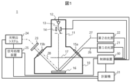
- FIG. 1 is a schematic configuration diagram of an inspection apparatus of Example 1.
- FIG. It is an example of a control sequence for controlling the electronic state of a sample. It is an example of a control sequence for controlling the electronic state of a sample. It is an example of a control sequence for controlling the electronic state of a sample. It is an example of a detected signal spectrum. It is an example of a detected signal spectrum. It is an example of a data structure of a database for estimating film quality. It is a control flow for film quality inspection that can be estimated from the electric field dependence of the detected signal.
- FIG. It is an example of a control sequence for controlling the electronic state of a sample. It is an example of a control sequence for controlling the electronic state of a sample. It is an example of a detected signal spectrum. It is an example of a detected signal spectrum. It is an example of a data structure of a database for estimating film quality. It is a control flow for film quality inspection that can be estimated from the electric field dependence of the detected signal.
- FIG. 10 is a diagram showing changes in intensity of detection signals when sweeping the voltage applied to the charge control electrode; It is an example of the data structure of a database for estimating the film quality obtained from the electric field dependence of the detection signal. It is an example of a display of the result of a film-quality test. It is an example of a setting/measurement screen (setting tab). It is an example of a setting/measurement screen (measurement tab). It is an example of a result output screen.
- FIG. 11 is a schematic configuration diagram of an inspection apparatus of Modification 1; It is a figure which shows the relationship between a signal electron detection amount and an energy filter voltage.
- FIG. 11 is a schematic configuration diagram of an inspection apparatus of modification 2;
- FIG. 11 is a schematic configuration diagram of an inspection apparatus of Example 2;
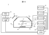
- FIG. 11 is a schematic configuration diagram of an inspection apparatus of Example 3;
- FIG. 11 is a schematic configuration diagram of an inspection apparatus of Example 4;
- the inspection apparatus of this embodiment evaluates film quality by optical inspection. That is, although a specific example will be described later, the material characteristics of the film are detected as the optical characteristics of the film, and information about the film quality is obtained from the detected optical characteristics.
- the electronic state of the sample to be inspected is modulated and controlled by charge control of the film to be inspected and/or internal electric field control by light irradiation.
- the purpose of controlling the electric field strength on the film to be inspected can be roughly divided into two.
- the first is to optimize the conditions of optical inspection. For example, by performing an optical inspection under an electric field strength that can obtain the maximum signal light intensity, it is possible to perform an inspection with a high SNR, and improve the inspection throughput.
- the second is to examine field-dependent film quality. Information on the film quality can be obtained by changing the applied electric field strength and detecting changes in the detection signal for the material properties that depend on the electric field strength. Details will be described later.
- the object to be inspected is an insulating film formed on a semiconductor wafer and its interface, but the application of this technology is not limited to this.
- Film quality measurement under an electric field is also effective for, for example, semiconductor films, organic films, and their interfaces.
- Fig. 1 shows a schematic configuration of the inspection apparatus 1 of the first embodiment.
- the inspection apparatus 1 has, as main components, a charged particle beam device for controlling the electronic state of the sample to be inspected in the sample, a light irradiation system for irradiating the sample with probe light, and It has a photodetection system for detecting signal light and a control system for controlling them.
- the charged particle beam device includes a sample chamber 10 and a lens barrel 11, the insides of which are kept in a vacuum atmosphere by an exhaust mechanism (not shown).
- a sample chamber 10 accommodates a sample 16 such as a semiconductor wafer.
- a charged particle source 12 for generating a charged particle beam 13 to irradiate a sample 16 and a blanker 14 for chopping the charged particle source 12 are accommodated in the lens barrel 11 .
- the charged particle source 12 it is sufficient to generate the charged particle beam 13 for charging the sample 16, and an electron gun, a flood gun, an ion source, or the like can be used.
- charged particle optical components such as lenses and deflectors that form a charged particle optical system for guiding the charged particle beam 13 to the sample 16 may be provided.
- a charge control electrode 17 is provided near the sample 16 to control the charge amount of the sample 16 by controlling the electric field on the sample 16 .
- the electric field directly above the sample 16 is controlled by applying a voltage to the charge control electrode 17 .
- the electric field applied to the charge control electrode 17 causes secondary charged particles generated when the charged particle beam 13 is applied to the sample 16 to move away from or push back from the sample 16, thereby controlling the charged state of the sample 16.
- the charge control electrode 17 is arranged at a position separated from the sample 16 by several to 30 mm, for example. For this reason, it is desirable to use a metal mesh or a perforated electrode plate so as not to interfere with irradiation of the charged particle beam 13 or probe light 26 or pump light 27 (to be described later) onto the sample 16 .
- the charge of the sample 16 can be quickly removed by using ultraviolet light as disclosed in Patent Document 1.
- ultraviolet light As disclosed in Patent Document 1.
- a second light source 22 is provided to irradiate the sample 16 with light (referred to as pump light (second light) 27).
- pump light second light
- the electronic state of the sample to be inspected can be controlled, and by selecting the wavelength of the pump light 27, the content of the electronic state to be controlled can be changed.
- the second light source 22 can be configured in the same manner as the first light source 21 described later.
- the inspection apparatus 1 includes a first light source 21 that irradiates the sample 16 with probe light (first light) 26 in order to optically inspect a film to be inspected formed on the sample 16 .
- a white light source such as a xenon lamp, a laser, an LED, or the like can be used.
- a white light source can also be used after being monochromatized through a monochromator.
- the light irradiation system includes optical components such as lenses and mirrors constituting an optical system for guiding the probe light 26 to the sample 16 and a polarizer for controlling the polarization of the probe light 26. ing.
- the first light source 21 is arranged outside the sample chamber 10, and the probe light 26 is introduced into the sample chamber 10 through the view port 15a provided in the sample chamber 10.
- the pump light 27 is also introduced into the sample chamber 10 through the viewport 15a, but the probe light 26 and the pump light 27 may be introduced into the sample chamber 10 through different viewports.
- Signal light 28 is generated by irradiating the sample 16 with the probe light 26 .
- the signal light 28 includes reflected light, scattered light (including Raman scattered light), emitted light, and diffracted light.
- the photodetection system detects signal light 28 and includes an optical filter 23 , a photodetection system 24 and a signal processor 25 .
- the optical filter 23 is a filter that removes light other than the signal light 28
- the light detection system 24 detects the signal light 28 by receiving the light transmitted through the viewport 15 b through the optical filter 23 .
- a power meter, photodiode, spectrometer, or the like can be used according to the signal light 28 to be detected.
- the signal processor 25 processes the detection signals of the photodetection system obtained under the electric field conditions inside a plurality of samples.
- the signal processor 25 is, for example, a lock-in amplifier, and extracts the modulation intensity, phase, etc. of the detection signal from the photodetection system 24 .
- the signal light 28 detected by the photodetection system 24 is determined according to the film quality of the film to be inspected. For example, information such as interfacial electric field, defects, and strain can be obtained by detecting reflected light, information such as vibration level, stress, and strain can be obtained by detecting scattered light (including Raman scattered light), and luminescence can be detected. By detecting the diffracted light, information such as structural periodicity and refractive index can be obtained.
- the control device 30 controls components of the inspection device 1 .
- the control device 30 controls the operation of the charged particle beam device, the light irradiation system, and the light detection system, for example, based on inspection conditions input from the computer 31 .
- the control device 30 is implemented by a program executed by a processor such as a CPU. Alternatively, for example, it may be configured by FPGA (Field-Programmable Gate Array), ASIC (Application Specific Integrated Circuit), or the like.
- the computer 31 executes the inspection by the inspection device 1, the setting of measurement conditions, and the estimation of the film quality based on the detection signal from the photodetection system.
- the calculator 31 stores various databases or conversion formulas necessary for setting conditions and estimating film quality.
- the setting of inspection and measurement conditions includes the setting of the following parameters. These parameters are set by the user through the GUI of the computer 31 .
- the conditions of the charged particle beam 13 that charges the sample include acceleration voltage, current amount, irradiation area, irradiation position, and irradiation cycle by a blanker.
- the conditions of the charge control electrode 17 for controlling the charge amount of the sample include the voltage value and its application period.
- the conditions of the pump light 27 that control static electricity removal or the internal electric field of the sample include wavelength, intensity, polarization, irradiation period, and the like.
- Conditions of the probe light 26 include wavelength, intensity, polarization, and the like.
- Detector conditions of the photodetection system 24 include gain and the like.
- Figures 2A to 2C show an example of a control sequence that modulates the electronic state of the sample. Both examples are control sequences for controlling the electronic state of the sample 16 by three action sources, the charged particle beam 13 , the charge control electrode 17 and the pump light 27 .
- the conditions of the charged particle beam 13 and charge control electrode 17 are fixed, and the conditions of the pump light 27 are modulated.
- the parameter to be modulated may be wavelength or polarization, but intensity is used here.
- the intensity of the pump light 27 is ON, the charge of the sample 16 is removed or the electric field inside the sample is controlled depending on the wavelength of the pump light 27 .
- FIG. 2B the conditions of the charged particle beam 13 and the pump light 27 are fixed, and the conditions of the charge control electrode 17 are modulated.
- FIG. 2C fixes the conditions of the charge control electrode 17 and the pump light 27 and modulates the conditions of the charged particle beam 13 .
- Any parameter of at least one of the three action sources may be modulated so that the electronic state of the sample 16 is modulated.
- the modulation patterns of the multiple sources may be the same or different.
- the pump light 27 has a short wavelength and is used for the purpose of neutralizing the film to be inspected, and if it is sufficient to control only the presence or absence of the charge on the sample, the charge control electrode 17 can be eliminated.
- the second light source 22 when the charged particle beam 13 and charge control electrode 17 modulate the charge amount of the sample, the second light source 22 can be omitted.
- the second light source 22 capable of irradiating light with a wavelength longer than that of the ultraviolet light, and the If it is desired to reset the charge amount, it is effective to provide the second light source 22 capable of irradiating ultraviolet light.
- the detection signal output by the photodetection system after detecting the signal light 28 is sampled according to a sampling trigger.
- the sampling trigger is synchronized with the modulation of the electronic state of the sample.
- the intensity S A of the signal light 28 when the source to be modulated is in the first state the intensity of the pump light 27 is OFF in the example of FIG. 2A
- the source to be modulated is in the second state
- the intensity S B of the signal light 28 can be obtained when the intensity of the pump light 27 is ON
- information about the film quality of the film to be inspected can be obtained.
- the sampling trigger has various aspects depending on the configuration of the photodetection system, and is not limited to any particular aspect.
- the second light source 22 modulates the pump light 27 in synchronization with the synchronization signal from the control device 30 and the photodetection system continuously outputs detection signals from the signal processing device 25 .
- the computer 31 can receive the synchronization signal from the control device 30 and sample the detection signal from the signal processing device 25 with a sampling trigger synchronized with the synchronization signal.
- the photodetection system 24 continuously outputs a detection signal
- the signal processing device 25 receives a synchronization signal from the control device 30, and the detection from the photodetection system 24 is performed by a sampling trigger synchronized with the synchronization signal. It may be configured to sample a signal and perform signal processing. Further, in the photodetection system, the photodetection system 24 may receive a synchronizing signal from the control device 30 and may detect the signal light 28 by a sampling trigger synchronized with the synchronizing signal. This configuration is preferred when the detector of photodetection system 24 is a spectrometer.
- Signal processing of the signal processing device 25 in the photodetection system will be described.
- the detector in the photodetection system 24 is a power meter and the signal light 28 is the reflected light of the probe light 26 .
- the signal intensity S A of the signal light 28 in the first state and the signal intensity S B of the signal light 28 in the second state are assumed.
- the signal processing device 25 normalizes the difference between the signal intensities obtained in the two electronic states and outputs it as a detection signal.
- the detection signal is expressed as (Equation 1), which means the rate of change in reflectance.
- FIG. 3A shows the case where the voltage of the charge control electrode 17 is set to 0V
- FIG. 3B shows the case where the voltage of the charge control electrode 17 is set to +3V.
- the calculator 31 estimates the film quality, for example, the strain and dopant concentration of the semiconductor at the interface between the insulating film and the semiconductor, from the intensity and shape of the detected signal spectrum as shown in FIG. 3A or 3B.
- the obtained detection signal spectrum has, for example, a relationship represented by (Equation 3) (Non-Patent Document 1).
- A is intensity
- ⁇ is phase
- E energy
- ECP critical point energy
- ⁇ broadening factor
- n is a coefficient dependent on the material of the film to be inspected.
- (Formula 3) is fitted to the obtained detection signal spectrum. Fitting parameters (A, ⁇ , E CP , ⁇ ) included in (Equation 3) are obtained by fitting.
- the computer 31 holds film quality information for various combinations of fit parameters as a database.
- FIG. 4 shows an example of the database.
- FIG. 4 is an example data structure of the database 41 for estimating the film quality.
- film strain amounts (Strain) for combinations of fit parameters (A, ⁇ , E CP , ⁇ ) are registered.
- the computer 31 compares the fit parameter obtained from (Equation 3) with the database 41 to estimate the strain amount of the film to be inspected.
- the database 41 may register the film quality information as a function with the fit parameter as an argument, and the registration form is not limited.
- This example is an example in which a model formula such as Equation 3 and a database 41 are used when strain measurement is performed using the signal light 28 as the reflected light of the probe light 26.
- the signal light 28 is scattered light
- a model formula or database corresponding to the object may be used.
- the computer 31 stores the relationship between the parameters obtained from the detection signal and the film quality as a database, and estimates the film quality information from the parameters detected from the signal light 28 .
- the computer 31 has a database corresponding to the detection signal from the photodetection system and the analytical expression used in the film quality inspection performed by the inspection apparatus 1, and uses the database corresponding to the inspection to be performed to estimate the film quality.
- FIG. 5 shows a control flow for film quality inspection that can be estimated from the electric field dependence of such detection signals.
- a case of estimating the movable charge amount of a film to be inspected by applying the control sequence of FIG. 2A will be described as an example.
- variable parameter is the voltage applied to the charge control electrode 17 .
- a control sequence for film quality measurement is set. As described above, the control sequence of FIG. 2A is set (S02). After executing the control sequence and measuring the signal light 28 while changing the variable parameter (S03 to S06), and obtaining the detection signal for the range of the set variable parameter, a feature quantity indicating the dependence of the detection signal on the variable parameter is obtained. is calculated (S07).
- the computer 31 has a database of film quality information with respect to feature amounts that indicate variable parameter dependency of detection signals. This database is referenced to estimate the film quality of the film to be inspected (S08).
- FIG. 6 shows changes in intensity of the detection signal ( ⁇ R/R) when the voltage applied to the charge control electrode 17 is swept in the forward direction (from negative to positive) and the reverse direction (from positive to negative).
- the horizontal axis is the surface potential V s of the sample 16 . Since the surface potential Vs has a relationship with the applied voltage Vcc of the charge control electrode 17 as shown in (Equation 4), it can be obtained by converting from the applied voltage Vcc . (Formula 4) is obtained by simulation or the like.
- FIG. 7 is an example data structure of the database 51 for estimating the film quality obtained from the electric field dependence of the detection signal.
- the movable charge amount of the film is registered with respect to the combination of the feature amounts (V1, V2, ⁇ V) that indicate the electric field intensity dependence of the detection signal.
- the computer 31 compares the feature values (here, voltages V1, V2 and hysteresis that provide a specific reflectance) representing the electric field intensity dependence obtained from the measurement results as shown in FIG. Estimate the amount of mobile charge in the target membrane.
- the database 51 may register the film quality information as a function with the feature amount as an argument, and the registration form is not limited.
- FIG. 8 shows a display example of the result of optical inspection by the inspection device 1.
- Optical inspection is performed, for example, on user-designated chip sections on a semiconductor wafer.
- Optical inspection may be performed on the entire chip section.
- the film quality for each chip section subjected to optical inspection is displayed as a wafer heat map 60 .
- chip sections 62 are displayed in the wafer 61. For example, if the inspected film quality is defective, a chip section with a higher defect density is displayed in a darker color. This allows the user to visually recognize the film quality for each chip section.
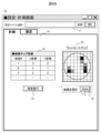
- FIG. 9A shows an example of a setting/measurement screen 70, which is a GUI (Graphical User Interface) for measuring film quality with the inspection device 1 and displaying the results.
- the setting/measurement screen 70 is provided with a setting file selection section 71, which can call the setting file saved in the computer 31 in the past measurement. For example, when inspecting different film qualities for the same wafer, the user's workload can be reduced by utilizing the past settings.
- control sequence tab 72 By selecting the control sequence tab included in the setting tab 72, the control sequences of FIGS. 2A to 2C or other control sequences can be selected.
- the laser modulation tab 73 is selected, and in this case, as shown in the sequence diagram 74, the control sequence for modulating the pump light shown as FIG. 2A is selected.
- an electron beam is used as the charged particle beam
- a laser beam is used as the pump light.
- the user opens the laser modulation tab 73 and sets the conditions for modulating the electronic state of the wafer in the electron beam condition setting section 75, charge control electrode condition setting section 76, and laser condition setting section 77. Furthermore, in this example, in order to estimate the film quality from the electric field dependence of the detection signal, the charge control electrode condition setting unit 76 is set to sweep the applied voltage. In this case, a sweep range setting section 78 is displayed, and the user sets the range for sweeping the applied voltage. When the above settings are completed, the save button 79 is pressed to save the set contents.
- the user After completing the condition setting, the user opens the measurement tab 81 as shown in FIG. 9B.
- the user designates a chip section for optical inspection in the inspection chip section setting section 82 and presses an inspection execution button 83 .
- optical inspection is performed on the designated chip section under the conditions set in the setting tab 72 .
- a wafer heat map is displayed on the wafer heat map display section 84 to simply show the inspection results to the user.
- the user confirms the inspection result and presses the save button 85 to save the optical inspection result.
- a result data file to be displayed in detail is called from a result file selection section 91 provided on the result output screen 90 .
- a wafer heat map display section 92 and a histogram display section 93 that display the same wafer heat map as the setting/measurement screen 70 are provided.
- the histogram displayed on the histogram display section 93 indicates the appearance frequency (the number of chip sections) of shades indicating the defect density in the wafer heat map displayed on the wafer heat map display section 92 .
- the inspection chip section measurement result display section 94 displays the measurement result of the detection signal in a specific chip section and the estimated film quality information.
- FIG. 10A shows a modification of the inspection apparatus 1 shown in FIG.
- the sample surface potential Vs is converted from the voltage Vcc applied to the charge control electrode 17 using (Equation 4). ) is obtained by simulations, etc.
- an error may occur between the value obtained from (Formula 4) and the true sample surface potential Vs.
- the inspection apparatus 1b of FIG. 10A has an energy filter 101 and a signal electron detector 102 as a mechanism for actually measuring the sample surface potential Vs of the sample 16.
- the signal electron detector 102 is a detector for detecting signal electrons 100 generated by irradiation of the sample 16 with the charged particle beam 13, and the signal electrons 100 to be detected are secondary electrons. may be reflected electrons (backscattered electrons).
- a negative voltage is applied to the energy filter 101 by the controller 30 , and only signal electrons that can overcome the electric field barrier caused by the negative voltage are detected by the signal electron detector 102 . That is, the amount of signal electrons detected by the signal electron detector 102 depends on the voltage of the energy filter 101 .
- the computer 31 of the inspection apparatus 1b calculates the sample surface potential Vs from the energy of the signal electrons 100.
- FIG. 10B shows the relationship between the amount of detected signal electrons and the energy filter voltage.
- a signal electron spectrum can be acquired by detecting the signal electron detection amount while changing the negative voltage applied to the energy filter 101 .
- the amount of shift depends on the sample surface potential Vs. This is because the force for pulling back the signal electrons 100 toward the sample changes depending on the sample surface potential Vs. If the signal electron spectrum 103 is the signal electron spectrum when the sample 16 is uncharged, the signal electron spectra 104 and 105 are the signal electron spectra when the sample 16 is positively charged and negatively charged, respectively.
- the sample surface potential Vs is defined as the voltage at which the differential value of the signal electron spectrum is maximum
- the potentials in the uncharged, positively charged, and negatively charged states are potentials V 0 , V 1 , and V 2 , respectively.
- the sample surface potential Vs can be actually measured without using the conversion formula (Equation 4).
- the signal electron spectrum 103 can be obtained by measuring the sample 16 in a state in which the charge is removed by the short wavelength pump light 27 such as ultraviolet light.
- the energy of the signal electrons 100 is discriminated using the energy filter 101, but the sample surface potential V It is possible to measure s .
- FIG. 11 shows a modification of the inspection apparatus 1 shown in FIG. Similar to Modification 1, Modification 2 also makes it possible to actually measure the sample surface potential Vs.
- the inspection apparatus 1 c has a surface potential meter 110 as a mechanism for actually measuring the sample surface potential Vs of the sample 16 .
- the sample 16 is moved to the position of the surface potential meter 110 provided in the sample chamber 10, and the sample surface potential Vs is measured.
- Example 1 the sample 16 is placed in a vacuum atmosphere, and it takes time to evacuate, which reduces the throughput of inspection measurement.
- Example 2 is a configuration example in which the sample 16 is placed in the air.
- the charged particle source 12 is arranged inside a lens barrel 11 that is in a vacuum atmosphere, and the lens barrel 11 is provided with a partition wall 120 for keeping the inside in a vacuum atmosphere.
- the charged particle beam 13 emitted from the charged particle source 12 passes through the partition wall 120 and is emitted to the atmosphere, and the sample 16 is irradiated with the beam.
- the charged particle source 12 is an electrode that generates ions by corona discharge in the atmosphere, the column 11 and the partition wall 120 for keeping the charged particle source in a vacuum atmosphere can be eliminated.
- Example 3 photoelectrons generated by irradiating a metal electrode with excitation light are used as charged particles.
- the inspection apparatus 3 of the third embodiment uses an electron beam source with a simple configuration as a charged particle beam source, and detects photoelectrons generated by irradiating the sample 16 and/or the charge control electrode 17 with short-wavelength light.
- the exchange can modulate the charge amount of the sample 16 .
- the third light source 131 and the fourth light source 132 are light sources that generate light with a wavelength of less than 400 nm, and their outputs are controlled by the control device 30 .
- the third light source 131 and the fourth light source 132 can be configured similarly to the first light source 21, respectively.
- a third light source 131 and a fourth light source 132 are arranged outside the sample chamber 10, and light from these light sources is introduced into the sample chamber 10 through a viewport 15c provided in the sample chamber 10. .
- the charge control electrode 17 is irradiated with the first excitation light (third light) 133 from the third light source 131 .
- a first photoelectron 135 is generated from a place irradiated with the first excitation light 133 . If the potential of the charge control electrode 17 is more negative than that of the sample 16 , the first photoelectrons 135 receive a force toward the sample and irradiate the sample 16 . Therefore, the sample 16 is negatively charged.
- the sample 16 is irradiated with the second excitation light (fourth light) 134 from the fourth light source 132 .
- a second photoelectron 136 is generated from a place irradiated with the second excitation light 134 . If the potential of the charge control electrode 17 is more positive than that of the sample 16 , the second photoelectrons 136 receive a force toward the charge control electrode and move away from the sample 16 . Therefore, the sample 16 is positively charged.
- the potential of the sample 16 can be modulated and controlled by the first photoelectrons 135 and the second photoelectrons 136 caused by the first excitation light 133 and the second excitation light 134 .
- the third light source 131 and the fourth light source 132 can also be used as one light source. Control.
- the configuration may be such that both the charge control electrode 17 and the sample 16 are irradiated with the excitation light at the same time.
- the third light source and the fourth light source may be arranged in a vacuum in order to avoid absorption of short wavelength light in the atmosphere.
- the arrangement of the charge control electrode 17 and the charged particle source 12 interferes with the probe light (first light) 26 and the pump light (second light) 27, and the light irradiation system , the photodetection system cannot be placed near the sample 16 . Therefore, it is difficult to focus the light on the sample, and the spatial resolution of the measurement is limited.
- an optical system such as an objective lens for probe light and signal light is arranged directly above the sample in order to obtain a high spatial resolution.
- an optical lens 141 for irradiating the sample 16 with the probe light 26 and the pump light 27 is positioned directly above the sample, and the optical axis thereof extends in a direction perpendicular to the film to be inspected formed on the sample. is located in Since the probe light 26 and the pump light 27 are focused on the sample 16 by the optical lens 141, measurement with high spatial resolution is possible.
- the charged particle source 12 is obliquely arranged with respect to the optical axis of the optical lens 141 , and the charged particle beam 13 passes between the optical lens 141 and the sample 16 and obliquely irradiates the sample 16 .
- the optical lens 141 also functions as a charge control electrode. That is, a transparent conductive film 17b is formed on the optical lens 141, and a voltage can be applied by the controller 30 while allowing the probe light 26, the pump light 27, and the signal light 28 to pass therethrough.
- a transparent conductive film 17b ITO, ITZO or the like may be used, or a metal thin film such as aluminum or gold may be used.
- the charge control electrode may be a transparent electrode and arranged under the optical lens 141 separately from the optical lens 141 .
- the probe light 26 and the pump light 27 are integrated on the same optical path using a dichroic mirror 142 having different transmission/reflection characteristics depending on the wavelength of the light.
- Signal light 28 propagates back through the optical path of probe light 26 , is reflected by beam splitter 143 , passes through optical filter 23 and is detected by photodetection system 24 .
- the probe light 26 is focused on the sample 16 by the optical lens 141, so that film quality measurement can be performed with high spatial resolution.
- the optical lens 141 is arranged in the vicinity of the sample 16, there is also the advantage that the detection rate for scattered light and emitted light from the sample 16 is improved.
- FIG. 14 illustrates only representative optical components that constitute the optical system, and omits general elements such as lenses and mirrors.
Landscapes
- Chemical & Material Sciences (AREA)
- Analytical Chemistry (AREA)
- Physics & Mathematics (AREA)
- Health & Medical Sciences (AREA)
- Life Sciences & Earth Sciences (AREA)
- Biochemistry (AREA)
- General Health & Medical Sciences (AREA)
- General Physics & Mathematics (AREA)
- Immunology (AREA)
- Pathology (AREA)
- Testing Or Measuring Of Semiconductors Or The Like (AREA)
Priority Applications (5)
| Application Number | Priority Date | Filing Date | Title |
|---|---|---|---|
| KR1020247019418A KR20240105432A (ko) | 2022-01-28 | 2022-01-28 | 검사 장치 및 막질 검사 방법 |
| PCT/JP2022/003391 WO2023145015A1 (ja) | 2022-01-28 | 2022-01-28 | 検査装置および膜質検査方法 |
| JP2023576531A JP7686797B2 (ja) | 2022-01-28 | 2022-01-28 | 検査装置および膜質検査方法 |
| US18/722,800 US20250046569A1 (en) | 2022-01-28 | 2022-01-28 | Inspection device and film quality inspection method |
| TW111150350A TWI856467B (zh) | 2022-01-28 | 2022-12-28 | 檢查裝置及膜質檢查方法 |
Applications Claiming Priority (1)
| Application Number | Priority Date | Filing Date | Title |
|---|---|---|---|
| PCT/JP2022/003391 WO2023145015A1 (ja) | 2022-01-28 | 2022-01-28 | 検査装置および膜質検査方法 |
Publications (1)
| Publication Number | Publication Date |
|---|---|
| WO2023145015A1 true WO2023145015A1 (ja) | 2023-08-03 |
Family
ID=87470952
Family Applications (1)
| Application Number | Title | Priority Date | Filing Date |
|---|---|---|---|
| PCT/JP2022/003391 Ceased WO2023145015A1 (ja) | 2022-01-28 | 2022-01-28 | 検査装置および膜質検査方法 |
Country Status (5)
| Country | Link |
|---|---|
| US (1) | US20250046569A1 (https=) |
| JP (1) | JP7686797B2 (https=) |
| KR (1) | KR20240105432A (https=) |
| TW (1) | TWI856467B (https=) |
| WO (1) | WO2023145015A1 (https=) |
Cited By (2)
| Publication number | Priority date | Publication date | Assignee | Title |
|---|---|---|---|---|
| WO2025253595A1 (ja) * | 2024-06-06 | 2025-12-11 | 株式会社日立ハイテク | 光照射装置、計測装置、および荷電粒子線装置 |
| WO2025262940A1 (ja) * | 2024-06-21 | 2025-12-26 | 株式会社日立ハイテク | 荷電粒子線装置および試料観察方法 |
Citations (7)
| Publication number | Priority date | Publication date | Assignee | Title |
|---|---|---|---|---|
| JPH11118738A (ja) * | 1997-10-14 | 1999-04-30 | Advantest Corp | 微小な測定対象物を高速に分析できる分析装置 |
| JP2000357483A (ja) * | 1999-06-11 | 2000-12-26 | Hitachi Ltd | 荷電粒子線画像に基づく検査または計測方法およびその装置並びに荷電粒子線装置 |
| JP2008027737A (ja) * | 2006-07-21 | 2008-02-07 | Hitachi High-Technologies Corp | パターン検査・計測装置 |
| JP2009043960A (ja) * | 2007-08-09 | 2009-02-26 | Panasonic Corp | 欠陥画像自動収集方法 |
| JP2010097768A (ja) * | 2008-10-15 | 2010-04-30 | Topcon Corp | 複合型観察装置 |
| US20150125065A1 (en) * | 2013-11-04 | 2015-05-07 | Kla-Tencor Corporation | Method and System for Correlating Optical Images with Scanning Electron Microscopy Images |
| JP2017535914A (ja) * | 2014-09-17 | 2017-11-30 | オルボテック エルティーディーOrbotech Ltd. | 検査、テスト、デバッグ、及び表面の改変のための電子ビーム誘導プラズマ(eBIP)の適用 |
Family Cites Families (5)
| Publication number | Priority date | Publication date | Assignee | Title |
|---|---|---|---|---|
| JP4828162B2 (ja) | 2005-05-31 | 2011-11-30 | 株式会社日立ハイテクノロジーズ | 電子顕微鏡応用装置および試料検査方法 |
| KR102347057B1 (ko) * | 2015-08-12 | 2022-01-03 | 케이엘에이 코포레이션 | 전자 빔 이미지에서의 결함 위치 결정 |
| WO2020234987A1 (ja) * | 2019-05-21 | 2020-11-26 | 株式会社日立ハイテク | 荷電粒子線装置 |
| JP7148467B2 (ja) * | 2019-08-30 | 2022-10-05 | 株式会社日立ハイテク | 荷電粒子線装置 |
| WO2022091180A1 (ja) * | 2020-10-26 | 2022-05-05 | 株式会社日立ハイテク | 荷電粒子線装置 |
-
2022
- 2022-01-28 WO PCT/JP2022/003391 patent/WO2023145015A1/ja not_active Ceased
- 2022-01-28 US US18/722,800 patent/US20250046569A1/en active Pending
- 2022-01-28 JP JP2023576531A patent/JP7686797B2/ja active Active
- 2022-01-28 KR KR1020247019418A patent/KR20240105432A/ko active Pending
- 2022-12-28 TW TW111150350A patent/TWI856467B/zh active
Patent Citations (7)
| Publication number | Priority date | Publication date | Assignee | Title |
|---|---|---|---|---|
| JPH11118738A (ja) * | 1997-10-14 | 1999-04-30 | Advantest Corp | 微小な測定対象物を高速に分析できる分析装置 |
| JP2000357483A (ja) * | 1999-06-11 | 2000-12-26 | Hitachi Ltd | 荷電粒子線画像に基づく検査または計測方法およびその装置並びに荷電粒子線装置 |
| JP2008027737A (ja) * | 2006-07-21 | 2008-02-07 | Hitachi High-Technologies Corp | パターン検査・計測装置 |
| JP2009043960A (ja) * | 2007-08-09 | 2009-02-26 | Panasonic Corp | 欠陥画像自動収集方法 |
| JP2010097768A (ja) * | 2008-10-15 | 2010-04-30 | Topcon Corp | 複合型観察装置 |
| US20150125065A1 (en) * | 2013-11-04 | 2015-05-07 | Kla-Tencor Corporation | Method and System for Correlating Optical Images with Scanning Electron Microscopy Images |
| JP2017535914A (ja) * | 2014-09-17 | 2017-11-30 | オルボテック エルティーディーOrbotech Ltd. | 検査、テスト、デバッグ、及び表面の改変のための電子ビーム誘導プラズマ(eBIP)の適用 |
Cited By (2)
| Publication number | Priority date | Publication date | Assignee | Title |
|---|---|---|---|---|
| WO2025253595A1 (ja) * | 2024-06-06 | 2025-12-11 | 株式会社日立ハイテク | 光照射装置、計測装置、および荷電粒子線装置 |
| WO2025262940A1 (ja) * | 2024-06-21 | 2025-12-26 | 株式会社日立ハイテク | 荷電粒子線装置および試料観察方法 |
Also Published As
| Publication number | Publication date |
|---|---|
| TWI856467B (zh) | 2024-09-21 |
| US20250046569A1 (en) | 2025-02-06 |
| TW202331771A (zh) | 2023-08-01 |
| JPWO2023145015A1 (https=) | 2023-08-03 |
| KR20240105432A (ko) | 2024-07-05 |
| JP7686797B2 (ja) | 2025-06-02 |
Similar Documents
| Publication | Publication Date | Title |
|---|---|---|
| CN112219111B (zh) | 使用于晶片噪声公害识别的扫描式电子显微镜及光学图像相关 | |
| US8586920B2 (en) | Charged particle beam apparatus | |
| JP7148467B2 (ja) | 荷電粒子線装置 | |
| JP6998469B2 (ja) | 電子線装置 | |
| JP2012032239A (ja) | 試料検査装置及び試料検査方法 | |
| TWI856467B (zh) | 檢查裝置及膜質檢查方法 | |
| US12326410B2 (en) | Electron spectroscopy based techniques for determining various chemical and electrical characteristics of samples | |
| JP5009506B2 (ja) | 試料の1つ又は複数の特性を決定するための方法とシステム | |
| US20240353352A1 (en) | Methods And Systems For Nanoscale Imaging Based On Second Harmonic Signal Generation And Through-Focus Scanning Optical Microscopy | |
| JP2002181725A (ja) | 微小異物解析方法、分析装置、半導体装置の製造方法および液晶表示装置の製造方法 | |
| JP5074262B2 (ja) | 帯電電位測定方法、及び荷電粒子顕微鏡 | |
| KR100955434B1 (ko) | 측정된 기초 스펙트럼을 사용하거나 및/또는 획득된스펙트럼에 기초한 박막의 비파괴적 특성화 | |
| US11107655B2 (en) | Charged particle beam device | |
| US12392733B2 (en) | Combined ocd and photoreflectance method and system | |
| JP2014182984A (ja) | 試料検査装置及び試料の検査方法 | |
| CN116952952B (zh) | 固体材料中电子点缺陷的探测方法、探测装置和系统 | |
| TW202500976A (zh) | 使用二次諧波產生之基於介面之缺陷檢查 | |
| KR20070113655A (ko) | 박막의 두께 측정 방법 및 이를 수행하기 위한 장치 | |
| JP6677943B2 (ja) | 顕微分光データ測定装置および方法 | |
| JP3361777B2 (ja) | マスク検査方法および検査装置 | |
| WO2024029060A1 (ja) | 試料測定装置 | |
| JP2957482B2 (ja) | 表面分析法およびその装置 | |
| TW202548966A (zh) | X射線光電子能譜(xps)測量 | |
| JP2010062255A (ja) | 半導体装置の解析方法および半導体解析装置 |
Legal Events
| Date | Code | Title | Description |
|---|---|---|---|
| 121 | Ep: the epo has been informed by wipo that ep was designated in this application |
Ref document number: 22923879 Country of ref document: EP Kind code of ref document: A1 |
|
| WWE | Wipo information: entry into national phase |
Ref document number: 2023576531 Country of ref document: JP |
|
| WWE | Wipo information: entry into national phase |
Ref document number: 1020247019418 Country of ref document: KR |
|
| WWE | Wipo information: entry into national phase |
Ref document number: 18722800 Country of ref document: US |
|
| NENP | Non-entry into the national phase |
Ref country code: DE |
|
| 122 | Ep: pct application non-entry in european phase |
Ref document number: 22923879 Country of ref document: EP Kind code of ref document: A1 |