WO2023139910A1 - 巻線負荷再現装置、マグネットワイヤ絶縁被膜の検査装置、マグネットワイヤ絶縁被膜の検査方法、および回転電機の製造方法 - Google Patents
巻線負荷再現装置、マグネットワイヤ絶縁被膜の検査装置、マグネットワイヤ絶縁被膜の検査方法、および回転電機の製造方法 Download PDFInfo
- Publication number
- WO2023139910A1 WO2023139910A1 PCT/JP2022/043008 JP2022043008W WO2023139910A1 WO 2023139910 A1 WO2023139910 A1 WO 2023139910A1 JP 2022043008 W JP2022043008 W JP 2022043008W WO 2023139910 A1 WO2023139910 A1 WO 2023139910A1
- Authority
- WO
- WIPO (PCT)
- Prior art keywords
- magnet wire
- load
- winding
- insulation coating
- reproducing
- Prior art date
- Legal status (The legal status is an assumption and is not a legal conclusion. Google has not performed a legal analysis and makes no representation as to the accuracy of the status listed.)
- Ceased
Links
Images






Classifications
-
- G—PHYSICS
- G01—MEASURING; TESTING
- G01N—INVESTIGATING OR ANALYSING MATERIALS BY DETERMINING THEIR CHEMICAL OR PHYSICAL PROPERTIES
- G01N27/00—Investigating or analysing materials by the use of electric, electrochemical, or magnetic means
- G01N27/02—Investigating or analysing materials by the use of electric, electrochemical, or magnetic means by investigating impedance
- G01N27/04—Investigating or analysing materials by the use of electric, electrochemical, or magnetic means by investigating impedance by investigating resistance
- G01N27/20—Investigating the presence of flaws
-
- G—PHYSICS
- G01—MEASURING; TESTING
- G01R—MEASURING ELECTRIC VARIABLES; MEASURING MAGNETIC VARIABLES
- G01R31/00—Arrangements for testing electric properties; Arrangements for locating electric faults; Arrangements for electrical testing characterised by what is being tested not provided for elsewhere
-
- G—PHYSICS
- G01—MEASURING; TESTING
- G01R—MEASURING ELECTRIC VARIABLES; MEASURING MAGNETIC VARIABLES
- G01R31/00—Arrangements for testing electric properties; Arrangements for locating electric faults; Arrangements for electrical testing characterised by what is being tested not provided for elsewhere
- G01R31/12—Testing dielectric strength or breakdown voltage ; Testing or monitoring effectiveness or level of insulation, e.g. of a cable or of an apparatus, for example using partial discharge measurements; Electrostatic testing
-
- G—PHYSICS
- G01—MEASURING; TESTING
- G01R—MEASURING ELECTRIC VARIABLES; MEASURING MAGNETIC VARIABLES
- G01R31/00—Arrangements for testing electric properties; Arrangements for locating electric faults; Arrangements for electrical testing characterised by what is being tested not provided for elsewhere
- G01R31/50—Testing of electric apparatus, lines, cables or components for short-circuits, continuity, leakage current or incorrect line connections
- G01R31/72—Testing of electric windings
Definitions
- This application relates to a winding load reproduction device, a magnet wire insulation coating inspection device, a magnet wire insulation coating inspection method, and a rotating electric machine manufacturing method.
- the magnet wires wound around the coils of the motor and transformer are electrically insulated by coating the surface with varnish. If defects such as flaws, air bubbles, pinholes and cracks are present in the varnish insulating film, they become electrically weak points, which can become starting points of breakdown when a voltage is applied.
- Patent Document 1 As a method for detecting film defects, a method for detecting defects before the magnet wire to be used is wound is disclosed (for example, Patent Document 1). Also, a method of immersing a wound coil in a conductive liquid to identify the position of a defect is disclosed (for example, Patent Document 2).
- the purpose of this application is to disclose a technique for solving the above-mentioned problems, and to reproduce the load applied to the magnet wire insulation coating when manufacturing a wound product, and to provide an apparatus and an inspection method for detecting defects in the insulation coating that occur.
- the winding load reproduction device disclosed in the present application includes a load reproduction mechanism that reproduces at least one load of friction or stretching on the insulation coating of the magnet wire, and simulates the occurrence of defects in the insulation coating of the magnet wire in the manufacture of wound products.
- a magnet wire insulation coating inspection apparatus disclosed in the present application includes a winding load reproduction device and a defect detection device for detecting defects in the magnet wire insulation coating.
- the magnet wire insulation coating inspection method disclosed in the present application is a method for detecting defects in the insulation coating of a magnet wire, and includes a back tensioner load reproduction step of reproducing the load on the insulation coating due to friction by applying a dynamic friction force to the passing magnet wire and pressing it from both sides, a winding nozzle load reproduction step of reproducing the load on the insulation coating due to friction with the end of the winding nozzle during winding of the magnet wire, and generating periodic and sharp tension fluctuations in the flow path of the magnet wire, so that the insulation coating is affected by tension fluctuations. It comprises a tension fluctuation load reproduction step of reproducing a load, and a defect detection step of detecting a defect of the insulating coating of the magnet wire.
- the method for manufacturing a rotating electrical machine disclosed in the present application includes the step of manufacturing a rotating electrical machine using a wound iron core using a magnet wire of the same lot as a magnet wire inspected by a magnet wire insulation coating inspection method and found to have no problem in the frequency of occurrence of defects in the insulation coating of the magnet wire due to a winding load.
- the winding load reproducing apparatus disclosed in the present application it is possible to reproduce the load applied to the magnet wire insulation coating when manufacturing the wound product.
- the magnet wire insulation coating inspection apparatus disclosed in the present application it is possible to provide an apparatus that reproduces the load applied to the magnet wire insulation coating when manufacturing a wound product and detects defects in the insulation coating that occur.
- the magnet wire insulation coating inspection method disclosed in the present application it is possible to reproduce the load applied to the magnet wire insulation coating when manufacturing a wound product, and to provide a method for detecting defects in the insulation coating that occurs.
- FIG. 1 is an overall configuration diagram of an inspection apparatus for a magnet wire insulating coating according to Embodiment 1.
- FIG. 4 is a schematic configuration diagram of a back tensioner load reproduction unit of the winding load reproduction device according to Embodiment 1;
- FIG. 4 is a schematic configuration diagram of a winding nozzle load reproduction unit of the winding load reproduction device according to Embodiment 1;
- FIG. 4 is a schematic configuration diagram of a tension fluctuation load reproducing section of the winding load reproducing device according to Embodiment 1.
- FIG. 4 is a perspective view of a dummy core rotating body of the tension fluctuation load reproducing section of the winding load reproducing device according to Embodiment 1.
- FIG. 4 is a schematic configuration diagram of a core corner load reproduction unit of the winding load reproduction device according to Embodiment 1.
- FIG. 4 is a perspective view of a corner reproduction rotor of a core corner load reproduction unit of the winding load reproduction device according to Embodiment 1.
- FIG. 4 is a schematic configuration diagram of a core corner load reproduction unit of the winding load reproduction device according to Embodiment 1.
- FIG. 1 is a perspective view of a corner reproduction rotor of a core corner load reproduction unit of the winding load reproduction device according to Embodiment 1.
- FIG. 4 is a schematic configuration diagram of a core corner load reproduction unit of the winding load reproduction device according to Embodiment 1.
- FIG. 2 is a configuration diagram of
- FIG. 10B is a structural conceptual diagram of an inspection object (rectangular wire type) of the magnet wire insulation coating inspection apparatus according to Embodiment 1.
- FIG. FIG. 4 is another block diagram of the defect detection device of the magnet wire insulation coating inspection device according to the first embodiment;
- FIG. 2 is a structural conceptual diagram of a conductive liquid replenishing mechanism of the magnet wire insulation coating inspection apparatus according to Embodiment 1;
- 4 is a flow chart of a magnet wire insulation coating inspection method according to Embodiment 1.
- FIG. FIG. 4 is an explanatory diagram of an example of application of the magnet wire insulation coating inspection method according to Embodiment 1 to a rotating electrical machine;
- FIG. 15A is a structural diagram of a wet electrode of a magnet wire insulation coating inspection apparatus according to Embodiment 2.
- FIG. 15B is a perspective view of a wet electrode of the magnet wire insulation coating inspection apparatus according to Embodiment 2.
- FIG. FIG. 16A is a structural diagram of a wet electrode of a magnet wire insulation coating inspection apparatus according to Embodiment 2.
- FIG. 16B is a perspective view of a wet electrode of the magnet wire insulation coating inspection apparatus according to Embodiment 2.
- FIG. 10 is a configuration diagram of a defect detection device of a magnet wire insulation coating inspection device according to Embodiment 3;
- Embodiment 1 is provided with a load reproduction mechanism that reproduces at least one load of friction or stretching on the insulation coating of the magnet wire, and simulates the occurrence of defects in the insulation coating of the magnet wire in the manufacture of wound products. Further, Embodiment 1 relates to a magnet wire insulation coating inspection apparatus equipped with a winding load reproducing apparatus. Furthermore, the present invention relates to a magnet wire insulation film inspection method using a winding load reproduction device, and a method of manufacturing a rotating electrical machine using a wound iron core using a magnet wire inspected by the magnet wire insulation film inspection method and found to have no problem in the frequency of occurrence of insulation film defects due to winding load.
- FIG. 1 is an overall configuration diagram of the magnet wire insulation coating inspection device
- FIG. 2 is a schematic configuration diagram of the back tensioner load reproduction unit of the winding load reproduction device
- FIG. 3 is a schematic configuration diagram of the winding nozzle load reproduction unit
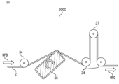
- FIG. 4 is a schematic configuration diagram of the tension fluctuation load reproduction unit
- FIG. 6, a perspective view of a corner reproducing rotor
- FIG. 9 a configuration diagram of a defect detection device of an inspection device for a magnet wire insulation coating
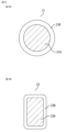
- FIG. 10A a structural conceptual diagram of an inspection object (round wire type)
- FIG. Description will be made based on FIG. 13, which is a flow chart of the insulating coating inspection method
- FIG. 13 is a flow chart of the insulating coating inspection method
- FIG. 13 is a flow chart of the insulating coating inspection method
- a magnet wire insulation coating inspection apparatus 100 according to Embodiment 1 includes a winding load reproduction apparatus 300, a defect detection apparatus 400, and a wire sweeping apparatus (servo motor 5, etc.) in order to inspect a magnet wire to be inspected.
- the wire sweeping device is a device for sweeping the magnet wire 2 to be inspected, It has a supply bobbin 1, a tensioner 3, a winding bobbin 4, a servomotor 5, and traverse mechanisms 6A and 6B.
- the arrow "WPD" represents the traveling direction of the magnet wire 2.
- FIG. 2 and subsequent figures When there is no need to distinguish between the traverse mechanisms 6A and 6B, they are referred to as the traverse mechanism 6 as appropriate.
- a magnet wire 2 as a material is pulled out from a supply bobbin 1 placed so that its axial direction is perpendicular to the ground.
- the drawn magnet wire 2 passes through the tensioner 3 , the winding load reproduction device 300 , the defect detection device 400 , the traverse mechanism 6 , and is wound on the winding bobbin 4 .
- the axial direction of the winding bobbin 4 is perpendicular to the traveling direction of the magnet wire 2 , and the axis rotates when power is transmitted from the servomotor 5 .
- the magnet wire 2 in the section from the tensioner 3 to the winding bobbin 4 is kept at a predetermined tension by the tensioner 3 .
- the magnet wire 2 is installed so as to be electrically connected through the end of the supply bobbin 1 on the winding start side.
- a chain and gears may be employed as the power transmission system as long as it is a mechanism for rotating the shaft of the winding bobbin 4.
- the winding load reproduction device 300 is arranged in the region between the traverse mechanism 6A and the traverse mechanism 6B after the tensioner 3, and installed at a place where the flow line of the magnet wire 2 crosses.
- the defect detection device 400 is arranged in an area between the winding load reproduction device 300 and the traverse mechanism 6B, and installed at a place where the flow line of the magnet wire 2 crosses.
- the winding load reproducing device 300 has a function of reproducing the load applied to the magnet wire in the course from being supplied from the bobbin to being wound around the core when production is performed by a general motor coil winding machine. That is, the winding load reproduction device 300 has a load reproduction mechanism that reproduces at least one load of friction or stretching on the insulation coating of the magnet wire, and can simulate the occurrence of defects in the insulation coating of the magnet wire in the manufacture of wound products.
- the magnet wire mainly has (1) a load due to friction with a tensioner, (2) a load due to friction with a winding nozzle, (3) a load due to tension fluctuations that occur when winding on a rectangular parallelepiped core, and (4) a load due to bending at the core corners when winding on a rectangular parallelepiped motor core.
- the winding load reproduction device 300 includes a back tensioner load reproduction section 300A, a winding nozzle load reproduction section 300B, a tension fluctuation load reproduction section 300C, and a core corner load reproduction section 300D as load reproduction mechanisms.
- the configuration, function, and operation of each load reproduction unit will be sequentially described with reference to FIGS. 2 to 8.
- the back tensioner load reproducing section 300A will be described with reference to FIG.
- the back tensioner load reproduction unit 300A reproduces the load due to friction with the tensioner in (1) above.
- P is "pressing".
- the back tensioner 31 sandwiches the magnet wire 2 between a plurality of sapphire plates 32, and applies dynamic friction to the passing magnet wire 2 to press it from both sides.
- An air cylinder or the like is used for the pressing force and its adjustment.
- the sapphire plate is used in this embodiment, other crystalline materials and felt materials may be used instead. Even when assuming an actual coil winding process, it is installed in front of the winding nozzle load reproducing section 300B in FIG.
- the winding nozzle load reproducing section 300B will be described with reference to FIG.
- the winding nozzle load reproduction unit 300B reproduces the load caused by friction with the winding nozzle in (2) above.
- the winding nozzle load reproduction unit 300B is provided with a hollow winding nozzle 33, a pulley 34, and a movable pulley 35, through which the magnet wire 2 is passed.
- the winding nozzle 33 and the pulley 34 are fixed in the magnet wire insulation film inspection apparatus 100 .
- the winding nozzle load reproduction unit 300B includes a hollow winding nozzle 33, and reproduces the load on the insulating coating due to friction with the end of the winding nozzle during winding of the magnet wire 2 passing through the winding nozzle.
- the movable pulley 35 can move the fixed position back and forth along the traveling direction of the magnet wire 2 after passing through the movable pulley 35 .
- the frictional load on the winding nozzle 33 that the magnet wire 2 receives can be arbitrarily adjusted.
- FIG. 4 is a side view of the tension fluctuation load reproducing section 300C.
- FIG. 5 is a perspective view of the dummy core rotor 36. As shown in FIG. Even when assuming an actual coil winding process, it is installed in the rear part of the winding nozzle load reproducing section 300B.
- the tension fluctuation load reproducing section 300C includes a dummy core rotating body 36, a dancer roller 37, and a pulley .
- the passing magnet wire 2 is wound around the dummy core rotor 36 one or more times as shown in the perspective view of the dummy core rotor 36 in FIG.
- the dummy core rotator 36 rotates, it generates periodic and sharp tension fluctuations in the movement line path because of its square and rectangular cross-sectional shape. Therefore, the tension fluctuation load in the actual spindle winding can be reproduced.
- the dancer roller 37 absorbs tension fluctuations that occur in subsequent flow paths.
- a guide having a larger area than the cross-sectional shape is provided at the axial end of the dummy core rotor 36 so that the magnet wire 2 does not fall off during rotation.
- the side surface of the dummy core rotor 36 is desirably made of a material having a large frictional force so that the magnet wire 2 in contact therewith does not slip.
- the cross-sectional shape of the dummy core rotating body 36 can be matched with the cross-sectional shape of the motor core that is assumed to be used in production.
- the tension fluctuation load reproducing unit 300C includes the dancer roller 37 and the rectangular parallelepiped dummy core rotor 36.
- FIG. 6 is a side view of the core corner load reproducing section 300D.
- FIG. 7 is a perspective view of the corner reproduction rotator 38.
- FIG. 8 is a side view of a core corner load reproduction unit 300D using a round corner reproduction rotator 39.
- FIG. 6 is a side view of the core corner load reproducing section 300D.
- FIG. 7 is a perspective view of the corner reproduction rotator 38.
- FIG. 8 is a side view of a core corner load reproduction unit 300D using a round corner reproduction rotator 39.
- the core corner load reproduction unit 300 ⁇ /b>D includes a rectangular parallelepiped corner reproduction rotor 38 and a pulley 34 .
- the position of the pulley 34 is adjusted so that the passing magnet wire 2 is bent at a right angle at the corner reproducing rotor 38 as shown in the perspective view of the corner reproducing rotor 38 in FIG.
- the corner reproduction rotator 38 rotates, due to its square cross-sectional shape, a maximum 90° periodic bend occurs in the flow line path. Therefore, the bending load of the magnet wire at the core corner of the actual spindle winding can be reproduced.
- a guide having a larger area than the cross-sectional shape is provided to prevent the magnet wires 2 from falling off during rotation, as is the case with the dummy core rotor 36. It is desirable to use a material with a large frictional force for the side surface of the corner reproduction rotor 38 so that the magnet wire 2 in contact therewith does not slip.
- the cross-sectional shape of the corner reproduction rotator 38 can be matched with the radius of the corner of the motor core that is assumed to be used in production.
- the tension fluctuation load reproduction unit 300C can also reproduce the bending load of the magnet wire at the core corner by the dummy core rotor 36, but if the core corner load reproduction unit 300D is used, the circumference of the corner reproduction rotor 38 can be made shorter than the motor core. As a result, the bending load at the corners of the core can be reproduced on the magnet wire with a higher density than in the case of the motor core with the same wire length.
- the core corner load reproduction section in FIG. 8 is referred to as a continuous bending core corner load reproduction portion. When collectively described without distinction, it is described as a core corner load reproduction portion.
- the winding nozzle load reproduction unit 300B in FIG. 3 moves the movable pulley 35 directly below the nozzle exit and changes the route so that the magnet wire 2 is bent 90° at the nozzle exit.
- the load on the magnet wire in the magnet wire flow path of the flyer winding machine is basically the same as that of the spindle winding machine.
- a load close to the actual situation can be reproduced.
- the defect detection apparatus 400 includes a conductive liquid tank 41, a conductive liquid 42, wet electrodes 43A and 43B, a metal electrode 44 whose lower portion is immersed in the conductive liquid 42, and a clamp 45 that holds the wet electrode 43 as equipment for applying a partial discharge detection voltage to the magnet wire 2.
- the defect detection device 400 further includes a power supply 46 for applying a detection voltage between the conductor of the magnet wire 2 and the surface of the insulating coating, a partial discharge detection device 47, and a personal computer 48 as devices for detecting partial discharge.
- "D1" represents the electrode width of the wet electrode 43
- a personal computer is described as "PC”.
- the wet electrodes 43A and 43B are referred to as the wet electrode 43 when there is no particular need to distinguish between them.
- a conductive liquid 42 is held inside the conductive liquid tank 41 .
- Rectangular parallelepiped wet electrodes 43A and 43B made of a soft and hygroscopic felt material are provided above the conductive liquid tank 41 .
- a magnet wire 2 is arranged between the wet electrodes 43A and 43B.
- the wet electrodes 43A, 43B are held against the magnet wire 2 by clamps 45 fixed to the conductive liquid bath 41.
- FIG. That is, the rectangular parallelepiped wet electrodes 43A and 43B are in contact with each other so as to sandwich the magnet wire 2 therebetween.
- the wet electrode 43 whose lower part is immersed in the conductive liquid 42 is wet with the conductive liquid 42 because it is hygroscopic. Furthermore, since the wet electrode 43 is soft, it is pressed against the magnet wire 2 by the clamp 45, so that the wet electrode 43 is in contact with the entire circumference of the magnet wire 2 in the region of the electrode width D1. That is, the conductive liquid 42 is in contact with the entire circumference of the magnet wire 2 in the region of the electrode width D1 of the wet electrode 43 . This configuration allows the conductive liquid 42 to efficiently contact the surface of the magnet wire 2 .
- the magnet wire 2 slides while maintaining the contact area of the wet electrode 43 and the electrode width D1 by the winding operation on the winding bobbin 4 in FIG.
- a metal electrode 44 connected to a power supply 46 and a partial discharge detection device 47 is immersed in the conductive liquid 42 at its lower portion and used as an electrode for applying a partial discharge detection voltage to the conductive liquid 42 . Furthermore, since the wet electrodes 43A and 43B are wetted with the conductive liquid 42, when the power supply 46 is connected, the partial discharge detection voltage is applied to the entire circumference of the magnet wire 2 in the area of the electrode width D1 of the wet electrode 43.
- FIG. 10A is a round magnet wire 21, and is a cross-sectional view taken perpendicularly to the axial direction.
- the magnet wire 21 has a conductor 21A at the center of the shaft, and the entire surface of the conductor 21A is covered with an insulating film 21B with a predetermined film thickness.
- FIG. 10B is a rectangular wire-shaped magnet wire 22, and is a cross-sectional view taken perpendicularly to the axial direction.
- the basic configuration is the same as the round wire type shown in FIG. 10A except that the conductor 22A and the insulating coating 22B have square cross-sectional shapes.
- the magnet wire 21 (22) Since the magnet wire 21 (22) has such a configuration, it is possible to continuously detect electrical defects in the insulating coating 21B (22B) of the magnet wire 21 (22) by the following measuring method.
- the magnet wire 21 is for the round wire type
- the magnet wire 22 is for the rectangular wire type.
- the magnet wire 2 is used, and when necessary, the round magnet wire 21 is described as a representative example.
- each load reproduction unit of the winding load reproduction device 300 is individually attachable and detachable, it is possible to isolate and verify the cause of the defect. That is, according to the configuration of the present embodiment, it is possible to determine whether the defect occurring in the magnet wire 2 is the effect of the load due to the winding nozzle, the effect of the load due to the back tensioner 31, or the properties of the magnet wire strand. As a result, appropriate countermeasures can be taken in the development of wire wound products, such as changing the design of the nozzle tip shape of the winding machine, reducing the pressing force of the back tensioner 31, or changing the magnet wire 2 to a grade with high wear resistance.
- the magnet wire insulation coating inspection device 100 is assumed to be used for selecting magnet wire materials and considering the load design in the winding machine, and basically the inspected magnet wires are not reused for production.
- a stator used in a rotary electric machine may be manufactured using a magnet wire manufactured in the same production lot as a magnet wire that has been inspected and found to have no problem in the frequency of occurrence of insulation film defects due to winding load.
- the power supply 46 is connected to the conductor 21A of the magnet wire 2 and the metal electrode 44, and an AC voltage is applied to the outer peripheral surface of the magnet wire 2 in the area of the electrode width D1 of the wet electrode 43.
- the conductive liquid 42 is in direct contact with the conductor 21A inside the insulating coating 21B, so current is detected when voltage is applied, and the insulation defect can be detected in the electrode width D1 area.
- the magnet wire 2 when the winding operation is performed in the magnet wire insulation film inspection device 100 , the magnet wire 2 always passes through the electrode width D1 area of the wet electrode 43 of the defect detection device 400 . Therefore, it is possible to detect defects occurring during manufacturing and due to winding loads in the entire region of the magnet wire 2 unwound from the supply bobbin 1 .
- defects in the insulating coating can be detected. That is, by applying an AC voltage of a predetermined magnitude, partial discharge is generated between the conductive liquid 42 that wets the wet electrode 43 and the magnet wire 2, and the partial discharge detector 47 detects the electric charge.
- the discharge charge amount detected when the insulating coating 21B has defects such as air bubbles or cracks is greater than when there are no defects.
- the wet electrode 43 is soft, the rectangular wire magnet wire 22 shown in FIG. 10B is also applicable.
- the felt material is mentioned as the material of the wet electrode 43, it is sufficient that it is water-absorbent, soft enough to adhere along the curved surface of the magnet wire 2 used, and has conductivity.
- a sponge material such as sponge may be used. That is, the wet electrode 43 may be a sponge electrode.
- Volatile alcohols such as methyl alcohol and ethyl alcohol can be used for the conductive liquid 42 .
- the conductive liquid 42 may be a liquid other than alcohol, but it needs to have high conductivity and low viscosity to penetrate defects such as pinholes in the magnet wire 2 .
- the conductive liquid 42 must also have the property of being quickly removed after passing through the detection area of the electrode width D1 of the wet electrode 43 .
- the clamp 45 is used to press the wet electrodes 43A, 43B against the magnet wire 2, and also has the role of suppressing the evaporation of the conductive liquid 42 from the surfaces of the wet electrodes 43A, 43B in air.
- the material of the clamp 45 may be resin or metal, but by using a conductive metal material such as copper or iron, the metal electrode 44 can be eliminated as described below.
- a defect detection device 401 in FIG. 11 has the same basic configuration as the defect detection device 400 in FIG. 9, but differs in a method of applying an AC voltage for detecting partial discharge.
- a defect detection device 401 is used to distinguish from the defect detection device 400 in FIG.
- the power source 46 and the partial discharge detection device 47 are directly connected to the clamp 45 to apply AC voltage and detect partial discharge.
- the conductive liquid tank 41 uses an insulating material and selects a material that does not dissolve in the conductive liquid 42 .
- a rectangular parallelepiped box shape with an open top is described, but any cubic, columnar, or conical shape may be used as long as it can hold the conductive liquid 42 .
- a float may be provided, or a lid may be provided on the upper surface of the conductive liquid tank 41 .
- the conductive liquid replenishing mechanism 450 of the inspection apparatus 100 for the magnet wire insulating coating will be described with reference to FIG.
- the wet electrode 43 should always be wetted with the conductive liquid 42 during inspection of the magnet wire 2 .
- both ends of the wet electrode 43 must always be positioned below the liquid surface of the conductive liquid 42 .
- the conductive liquid supply mechanism 450 includes a liquid supply tank 51 and a liquid supply mechanism liquid tank 50 having a valve 52 .
- a liquid level switch 53 is installed in the conductive liquid tank 41 , and a valve 52 is opened and closed according to the signal of the liquid level switch 53 . Specifically, when the conductive liquid 42 in the conductive liquid tank 41 falls below a predetermined minimum water level, the valve 52 is opened to supply the conductive liquid 42 from the liquid supply tank 51 into the conductive liquid tank 41 . When the conductive liquid 42 reaches the upper limit water level, the valve 52 is closed to stop the supply of the conductive liquid 42 .
- a float-type liquid level switch may be used instead of the electric liquid level switch.
- the conductive liquid supply mechanism 450 By providing the conductive liquid supply mechanism 450 in this manner, the conductive liquid 42 can be stably and continuously supplied to the wet electrode 43 . As a result, the wet electrode 43 can be kept wet at all times, and by applying an AC voltage to the conductive liquid 42 or to the wet electrode 43 via the metal electrode 44, partial discharge of the insulating coating of the magnet wire 2 can be stably detected.
- the back tensioner load reproduction step is indicated as "BLS”
- the winding nozzle load reproduction step as "WNS”
- the tension fluctuation load reproduction step as "TFS”.
- step 01 (S01) it is selected whether or not to carry out the back tensioner load reproduction step (S02). If the back tensioner load reproduction step (S02) is to be performed, proceed to step 02 (S02), otherwise proceed to step 03 (S03).
- step (S02) the load due to friction with the tensioner in the winding manufacturing process is reproduced. That is, by applying a dynamic frictional force to the passing magnet wire 2 and pressing it from both sides, the load on the insulating coating due to friction is reproduced.
- step 02 (S02) the process proceeds to step 03 (S03).
- step 03 select whether to implement the winding nozzle load reproduction step (S04). If the winding nozzle load reproduction step (S04) is to be carried out, proceed to step 04 (S04), otherwise proceed to step 05 (S05).
- step (S04) the load due to friction with the winding nozzle in the winding manufacturing process is reproduced. In other words, the load on the insulating coating due to friction with the end of the winding nozzle during winding of the magnet wire is reproduced.
- step 04 (S04) the process proceeds to step 05 (S05).
- step 05 select whether or not to implement the tension fluctuation load reproduction step (S06). If the tension fluctuation load reproduction step (S06) is to be carried out, the process proceeds to step 06 (S06); otherwise, the process proceeds to step 07 (S07).
- step (S06) the load due to the tension fluctuation generated when winding the rectangular parallelepiped core in the winding manufacturing process is reproduced. That is, by generating periodic and steep tension fluctuations in the flow path of the magnet wires 2, the load on the insulating coating caused by the tension fluctuations is reproduced.
- step 06 (S06) the process proceeds to step 07 (S07).
- an AC voltage is applied between the conductor of the magnet wire and the surface of the insulation coating to detect partial discharge, thereby detecting defects in the insulation coating of the magnet wire.
- a core corner load reproduction step can be added before the defect detection step (S07). That is, the load on the insulating coating due to bending at the corners of the motor core during winding of the magnet wire is reproduced by generating periodic bending or continuous bending.
- FIG. 14 shows a manufacturing method of a rotating electrical machine including a step of manufacturing a rotating electrical machine 80 having a stator core 72 wound by a nozzle 71 of a winding machine with a magnet wire 2 that is found to have no problem in the frequency of occurrence of insulation coating defects due to a winding load by applying a magnet wire insulation coating inspection method. That is, with this method for manufacturing a rotating electric machine, it is possible to manufacture a rotating electric machine that uses magnet wires that have been inspected by a highly reliable magnet wire insulation coating inspection method.
- This rotating electrical machine 80 can also be manufactured by a rotating electrical machine manufacturing method including a step of manufacturing a rotating electrical machine using a stator core 72 wound with a magnet wire 2 that has been found to have no problem in the frequency of occurrence of insulation coating defects due to a winding load by applying a magnet wire insulation film inspection device.
- the winding load reproducing apparatus of Embodiment 1 it is possible to reproduce the load applied to the magnet wire insulation coating when manufacturing a wound product.
- the magnet wire insulation coating inspection apparatus it is possible to reproduce the load applied to the magnet wire insulation coating when manufacturing a wound product, and to provide an apparatus for detecting defects in the insulation coating that occurs.
- the inspection method of the magnet wire insulation coating it is possible to reproduce the load received by the magnet wire insulation coating when manufacturing a wound product, and to provide a method of detecting defects in the insulation coating that occur.
- the method for manufacturing a rotating electrical machine it is possible to provide a rotating electrical machine that uses magnet wires that have been inspected by the magnet wire insulation film inspection method and have been found to have no problem in the frequency of occurrence of insulation film defects due to winding load.
- Embodiment 2 The magnet wire insulation coating inspection apparatus according to the second embodiment uses, as a wet electrode, an electrode of a different form from that of the first embodiment.
- FIGS. 15A and 16A are structural diagrams of the wet electrodes, and FIGS.
- FIGS. 15A and 16A are structural diagrams of the wet electrodes, and FIGS.
- the same reference numerals are given to the same or corresponding parts as in the first embodiment. Note that clamps and conductive liquid are omitted in each figure for clarity.
- FIGS. 15A and 15B the U-shaped wet electrode 43C in FIGS. 15A and 15B will be described.
- 43 C of U-shaped wet electrodes are described as 43 C of wet electrodes.
- the wet electrode 43 shown in FIG. 6 of Embodiment 1 is divided into two, ie, a wet electrode 43A and a wet electrode 43B, and has a configuration in which the magnet wire 2 is sandwiched between them. However, it may be shaped like the wet electrode 43C shown in FIGS. 15A and 15B.
- FIG. 15A shows a front view of the wet electrode 43C
- FIG. 15B shows a perspective view.
- the wet electrode 43C is, for example, a long rectangular parallelepiped wet electrode about twice as long as the wet electrodes 43A and 43B shown in FIG.
- the bent portion is formed so as to wrap the magnet wire 2 .
- the two portions extending from the U-shaped bent portion are in contact as shown in FIG. 15A.
- the wet electrode 43C can be formed in a similar shape, it is not necessary to form the electrode in one long rectangular parallelepiped shape.
- the wet electrode 43C With this configuration of the wet electrode 43C, it is possible to eliminate minute gaps between the contact surfaces of the wet electrodes 43A and 43B and the upper and lower surfaces of the magnet wire 2 shown in FIG. Therefore, the conductive liquid 42 can be brought into contact with the surface of the magnet wire 2 efficiently and more reliably.
- FIGS. 16A and 16B show a spiral wet electrode 43D shown in FIGS. 16A and 16B.
- the spiral wet-type electrode 43D is described as the wet-type electrode 43D.
- FIG. 16A shows a front view of the wet electrode 43D
- FIG. 16B shows a perspective view.
- the wet electrode 43D is a single long wet electrode having a length of about 2.5 to 3 times that of the wet electrodes 43A and 43B shown in FIG.
- the number of times of winding may be two or more.
- the magnet wire insulation coating inspection apparatus uses, as a wet electrode, an electrode of a different form from that of the first embodiment. Therefore, the magnet wire insulation coating inspection apparatus of the second embodiment can reproduce the load applied to the magnet wire insulation coating when manufacturing a wound product, and can detect defects in the insulation coating that occur. Furthermore, it is possible to reliably bring the conductive liquid into contact with the surface of the magnet wire.
- Embodiment 3 The defect detection device of the magnet wire insulation coating inspection device of Embodiment 3 uses dry electrodes instead of wet electrodes.
- FIG. 17 is a configuration diagram of the defect detection apparatus.
- the same reference numerals are given to the same or corresponding parts as in the first embodiment.
- the defect detection device 410 is used to distinguish from the first embodiment.
- a defect detection device 410 of FIG. 17 is obtained by changing the wet electrode 43 of the defect detection device 400 of FIG. 6 to a dry electrode 60 and eliminating the conductive liquid tank 41 .
- a soft carbon and conductive polymer material brush that does not damage the enamel coating layer is used for the dry electrode 60 .
- a conductive sponge can also be used as the material of the dry electrode 60 .
- the dry electrode 60 is installed so that the tip of the brush contacts the surface of the magnet wire 2 .
- the brushes are arranged so as to sandwich the round magnet wire 2 from above and below. This is the same for rectangular wire type magnet wires.
- partial discharge detection when a defect in the insulation coating of the magnet wire 2 passes through the area of the dry electrode 60 to which a voltage is applied, a partial discharge occurs between the dry electrode 60 and the defect in the insulation coating, and is detected by the partial discharge detection device 47.
- the tip of the brush of the dry electrode 60 may momentarily leave the surface of the magnet wire 2.
- the distance is about several millimeters, partial discharge occurs between the insulation film defect and the brush even if the surface of the magnet wire 2 is not directly touched, and the defect can be detected.
- the conductive liquid tank 41 and the conductive liquid 42 are not required, and the liquid supply mechanism liquid tank 50 for holding the conductive liquid 42 constant and related equipment are also unnecessary. This simplifies the facility and facilitates the operation of the defect detection apparatus.
- the defect detection device of the magnet wire insulation film inspection device of Embodiment 3 uses dry electrodes instead of wet electrodes. Therefore, the magnet wire insulation coating inspection apparatus of the third embodiment can reproduce the load applied to the magnet wire insulation coating when manufacturing a wire product, and can detect defects in the insulation coating that occur. Furthermore, the defect detection device is simplified and the operation is facilitated.
- the winding load reproduction device of the present application has a load reproduction mechanism that reproduces at least one load of friction or stretching on the insulation coating of the magnet wire, and simulates the occurrence of defects in the insulation coating of the magnet wire in the manufacture of winding products, so it can be widely applied to defect detection devices that detect defects in the insulation coating of magnet wires.
Landscapes
- Physics & Mathematics (AREA)
- General Physics & Mathematics (AREA)
- Chemical & Material Sciences (AREA)
- Chemical Kinetics & Catalysis (AREA)
- Electrochemistry (AREA)
- Health & Medical Sciences (AREA)
- Life Sciences & Earth Sciences (AREA)
- Analytical Chemistry (AREA)
- Biochemistry (AREA)
- General Health & Medical Sciences (AREA)
- Immunology (AREA)
- Pathology (AREA)
- Engineering & Computer Science (AREA)
- Power Engineering (AREA)
- Testing Of Short-Circuits, Discontinuities, Leakage, Or Incorrect Line Connections (AREA)
Priority Applications (2)
| Application Number | Priority Date | Filing Date | Title |
|---|---|---|---|
| CN202280089177.6A CN118742820A (zh) | 2022-01-24 | 2022-11-21 | 绕线载荷再现装置、磁导线绝缘覆膜的检查装置、磁导线绝缘覆膜的检查方法以及旋转电机的制造方法 |
| JP2023575087A JP7592196B2 (ja) | 2022-01-24 | 2022-11-21 | 巻線負荷再現装置、マグネットワイヤ絶縁被膜の検査装置、マグネットワイヤ絶縁被膜の検査方法、および回転電機の製造方法 |
Applications Claiming Priority (2)
| Application Number | Priority Date | Filing Date | Title |
|---|---|---|---|
| JP2022-008389 | 2022-01-24 | ||
| JP2022008389 | 2022-01-24 |
Publications (1)
| Publication Number | Publication Date |
|---|---|
| WO2023139910A1 true WO2023139910A1 (ja) | 2023-07-27 |
Family
ID=87347994
Family Applications (1)
| Application Number | Title | Priority Date | Filing Date |
|---|---|---|---|
| PCT/JP2022/043008 Ceased WO2023139910A1 (ja) | 2022-01-24 | 2022-11-21 | 巻線負荷再現装置、マグネットワイヤ絶縁被膜の検査装置、マグネットワイヤ絶縁被膜の検査方法、および回転電機の製造方法 |
Country Status (3)
| Country | Link |
|---|---|
| JP (1) | JP7592196B2 (https=) |
| CN (1) | CN118742820A (https=) |
| WO (1) | WO2023139910A1 (https=) |
Citations (5)
| Publication number | Priority date | Publication date | Assignee | Title |
|---|---|---|---|---|
| JPS5495889U (https=) * | 1977-12-20 | 1979-07-06 | ||
| JP2003248028A (ja) * | 2002-02-25 | 2003-09-05 | Nissan Motor Co Ltd | コイル傷検査装置、およびその方法 |
| JP2010210386A (ja) * | 2009-03-10 | 2010-09-24 | Nissan Motor Co Ltd | 絶縁検査装置 |
| JP2016180629A (ja) * | 2015-03-23 | 2016-10-13 | 日立金属株式会社 | 部分放電測定方法および部分放電測定装置、並びに絶縁電線の製造方法 |
| WO2022153821A1 (ja) * | 2021-01-14 | 2022-07-21 | 三菱電機株式会社 | 欠陥検出装置、欠陥検出方法、欠陥検出システムおよび回転電機の製造方法 |
Family Cites Families (4)
| Publication number | Priority date | Publication date | Assignee | Title |
|---|---|---|---|---|
| KR102544287B1 (ko) * | 2016-10-31 | 2023-06-15 | 스미토모 덴키 고교 가부시키가이샤 | 알루미늄 합금선, 알루미늄 합금 연선, 피복 전선, 및 단자 부착 전선 |
| CN209906093U (zh) * | 2019-05-21 | 2020-01-07 | 杭州双晨电缆有限公司 | 一种电缆自动成圈装置 |
| CN112489879B (zh) * | 2020-09-24 | 2022-09-13 | 深圳市华亿电讯实业有限公司 | 一种电力电缆生产设备及生产工艺 |
| CN113138117B (zh) * | 2021-04-29 | 2022-11-25 | 安徽联信电缆集团有限公司 | 一种电缆生产加工用耐磨性检测装置 |
-
2022
- 2022-11-21 WO PCT/JP2022/043008 patent/WO2023139910A1/ja not_active Ceased
- 2022-11-21 JP JP2023575087A patent/JP7592196B2/ja active Active
- 2022-11-21 CN CN202280089177.6A patent/CN118742820A/zh active Pending
Patent Citations (5)
| Publication number | Priority date | Publication date | Assignee | Title |
|---|---|---|---|---|
| JPS5495889U (https=) * | 1977-12-20 | 1979-07-06 | ||
| JP2003248028A (ja) * | 2002-02-25 | 2003-09-05 | Nissan Motor Co Ltd | コイル傷検査装置、およびその方法 |
| JP2010210386A (ja) * | 2009-03-10 | 2010-09-24 | Nissan Motor Co Ltd | 絶縁検査装置 |
| JP2016180629A (ja) * | 2015-03-23 | 2016-10-13 | 日立金属株式会社 | 部分放電測定方法および部分放電測定装置、並びに絶縁電線の製造方法 |
| WO2022153821A1 (ja) * | 2021-01-14 | 2022-07-21 | 三菱電機株式会社 | 欠陥検出装置、欠陥検出方法、欠陥検出システムおよび回転電機の製造方法 |
Also Published As
| Publication number | Publication date |
|---|---|
| CN118742820A (zh) | 2024-10-01 |
| JP7592196B2 (ja) | 2024-11-29 |
| JPWO2023139910A1 (https=) | 2023-07-27 |
Similar Documents
| Publication | Publication Date | Title |
|---|---|---|
| JP7378649B2 (ja) | 欠陥検出装置、欠陥検出方法、欠陥検出システムおよび回転電機の製造方法 | |
| JPWO2022153821A5 (https=) | ||
| JP7592196B2 (ja) | 巻線負荷再現装置、マグネットワイヤ絶縁被膜の検査装置、マグネットワイヤ絶縁被膜の検査方法、および回転電機の製造方法 | |
| CN113252732A (zh) | 一种漆包线漆膜完整性检测装置和方法 | |
| JP5949612B2 (ja) | 絶縁特性の検査装置、絶縁特性の検査方法及び絶縁電線の製造方法 | |
| US3417593A (en) | Method and apparatus for forming square or rectangular wire | |
| JPH0310211B2 (https=) | ||
| US3384815A (en) | Moisture content measuring method and apparatus including a roller for periodically contacting a flexible travelling sheet member | |
| US3917995A (en) | Movable brush assembly for making electrical contact with the outer surface of an electrical cable | |
| KR102883752B1 (ko) | 세퍼레이터의 제조 방법 및 세퍼레이터의 제조 장치 | |
| JP2009295292A (ja) | 超電導線材ラッピング装置および絶縁被覆付超電導線材の製造方法 | |
| JP5617179B2 (ja) | 被膜付電線の絶縁破壊試験装置及び絶縁破壊試験方法 | |
| JP4775904B2 (ja) | 巻線機 | |
| JP5353324B2 (ja) | 絶縁検査装置 | |
| JP2001221819A (ja) | 導電性繊維の電気抵抗測定方法及びその測定装置 | |
| JP7651062B2 (ja) | コイル製造装置、コイル製造方法、ステーター製造方法および回転電機製造方法 | |
| JPH10253694A (ja) | ケーブルの試験方法および手段 | |
| CN220357127U (zh) | 一种电线加工用的耐压试验设备 | |
| JP2016095926A (ja) | 絶縁電線及びその製造方法 | |
| JP2018174154A (ja) | 絶縁電線の製造方法 | |
| CN116753853A (zh) | 一种电线表皮绝缘层检测设备及方法 | |
| Riedel et al. | Evaluation of different methods for removing the conductor insulation of stranded conductors | |
| JPWO2023139910A5 (https=) | ||
| JP7329698B2 (ja) | マグネットワイヤ被覆の検査装置、マグネットワイヤ被覆の検査方法、および電気機械の製造方法 | |
| JP7525902B2 (ja) | 絶縁ロープの絶縁性確認方法およびそれに用いる絶縁性確認装置 |
Legal Events
| Date | Code | Title | Description |
|---|---|---|---|
| 121 | Ep: the epo has been informed by wipo that ep was designated in this application |
Ref document number: 22922061 Country of ref document: EP Kind code of ref document: A1 |
|
| WWE | Wipo information: entry into national phase |
Ref document number: 2023575087 Country of ref document: JP |
|
| WWE | Wipo information: entry into national phase |
Ref document number: 202280089177.6 Country of ref document: CN |
|
| NENP | Non-entry into the national phase |
Ref country code: DE |
|
| 122 | Ep: pct application non-entry in european phase |
Ref document number: 22922061 Country of ref document: EP Kind code of ref document: A1 |