WO2023139674A1 - 造形システム及び造形方法 - Google Patents
造形システム及び造形方法 Download PDFInfo
- Publication number
- WO2023139674A1 WO2023139674A1 PCT/JP2022/001729 JP2022001729W WO2023139674A1 WO 2023139674 A1 WO2023139674 A1 WO 2023139674A1 JP 2022001729 W JP2022001729 W JP 2022001729W WO 2023139674 A1 WO2023139674 A1 WO 2023139674A1
- Authority
- WO
- WIPO (PCT)
- Prior art keywords
- heating
- force
- support
- modeling
- modeling system
- Prior art date
- Legal status (The legal status is an assumption and is not a legal conclusion. Google has not performed a legal analysis and makes no representation as to the accuracy of the status listed.)
- Ceased
Links
Images









Classifications
-
- B—PERFORMING OPERATIONS; TRANSPORTING
- B23—MACHINE TOOLS; METAL-WORKING NOT OTHERWISE PROVIDED FOR
- B23K—SOLDERING OR UNSOLDERING; WELDING; CLADDING OR PLATING BY SOLDERING OR WELDING; CUTTING BY APPLYING HEAT LOCALLY, e.g. FLAME CUTTING; WORKING BY LASER BEAM
- B23K26/00—Working by laser beam, e.g. welding, cutting or boring
- B23K26/34—Laser welding for purposes other than joining
- B23K26/342—Build-up welding
-
- B—PERFORMING OPERATIONS; TRANSPORTING
- B22—CASTING; POWDER METALLURGY
- B22F—WORKING METALLIC POWDER; MANUFACTURE OF ARTICLES FROM METALLIC POWDER; MAKING METALLIC POWDER; APPARATUS OR DEVICES SPECIALLY ADAPTED FOR METALLIC POWDER
- B22F10/00—Additive manufacturing of workpieces or articles from metallic powder
- B22F10/20—Direct sintering or melting
- B22F10/25—Direct deposition of metal particles, e.g. direct metal deposition [DMD] or laser engineered net shaping [LENS]
-
- B—PERFORMING OPERATIONS; TRANSPORTING
- B22—CASTING; POWDER METALLURGY
- B22F—WORKING METALLIC POWDER; MANUFACTURE OF ARTICLES FROM METALLIC POWDER; MAKING METALLIC POWDER; APPARATUS OR DEVICES SPECIALLY ADAPTED FOR METALLIC POWDER
- B22F12/00—Apparatus or devices specially adapted for additive manufacturing; Auxiliary means for additive manufacturing; Combinations of additive manufacturing apparatus or devices with other processing apparatus or devices
- B22F12/10—Auxiliary heating means
- B22F12/17—Auxiliary heating means to heat the build chamber or platform
-
- B—PERFORMING OPERATIONS; TRANSPORTING
- B22—CASTING; POWDER METALLURGY
- B22F—WORKING METALLIC POWDER; MANUFACTURE OF ARTICLES FROM METALLIC POWDER; MAKING METALLIC POWDER; APPARATUS OR DEVICES SPECIALLY ADAPTED FOR METALLIC POWDER
- B22F12/00—Apparatus or devices specially adapted for additive manufacturing; Auxiliary means for additive manufacturing; Combinations of additive manufacturing apparatus or devices with other processing apparatus or devices
- B22F12/30—Platforms or substrates
-
- B—PERFORMING OPERATIONS; TRANSPORTING
- B23—MACHINE TOOLS; METAL-WORKING NOT OTHERWISE PROVIDED FOR
- B23K—SOLDERING OR UNSOLDERING; WELDING; CLADDING OR PLATING BY SOLDERING OR WELDING; CUTTING BY APPLYING HEAT LOCALLY, e.g. FLAME CUTTING; WORKING BY LASER BEAM
- B23K26/00—Working by laser beam, e.g. welding, cutting or boring
- B23K26/70—Auxiliary operations or equipment
- B23K26/702—Auxiliary equipment
-
- B—PERFORMING OPERATIONS; TRANSPORTING
- B29—WORKING OF PLASTICS; WORKING OF SUBSTANCES IN A PLASTIC STATE IN GENERAL
- B29C—SHAPING OR JOINING OF PLASTICS; SHAPING OF MATERIAL IN A PLASTIC STATE, NOT OTHERWISE PROVIDED FOR; AFTER-TREATMENT OF THE SHAPED PRODUCTS, e.g. REPAIRING
- B29C64/00—Additive manufacturing, i.e. manufacturing of three-dimensional [3D] objects by additive deposition, additive agglomeration or additive layering, e.g. by 3D printing, stereolithography or selective laser sintering
- B29C64/10—Processes of additive manufacturing
- B29C64/141—Processes of additive manufacturing using only solid materials
- B29C64/153—Processes of additive manufacturing using only solid materials using layers of powder being selectively joined, e.g. by selective laser sintering or melting
-
- B—PERFORMING OPERATIONS; TRANSPORTING
- B29—WORKING OF PLASTICS; WORKING OF SUBSTANCES IN A PLASTIC STATE IN GENERAL
- B29C—SHAPING OR JOINING OF PLASTICS; SHAPING OF MATERIAL IN A PLASTIC STATE, NOT OTHERWISE PROVIDED FOR; AFTER-TREATMENT OF THE SHAPED PRODUCTS, e.g. REPAIRING
- B29C64/00—Additive manufacturing, i.e. manufacturing of three-dimensional [3D] objects by additive deposition, additive agglomeration or additive layering, e.g. by 3D printing, stereolithography or selective laser sintering
- B29C64/20—Apparatus for additive manufacturing; Details thereof or accessories therefor
- B29C64/245—Platforms or substrates
-
- B—PERFORMING OPERATIONS; TRANSPORTING
- B33—ADDITIVE MANUFACTURING TECHNOLOGY
- B33Y—ADDITIVE MANUFACTURING, i.e. MANUFACTURING OF THREE-DIMENSIONAL [3D] OBJECTS BY ADDITIVE DEPOSITION, ADDITIVE AGGLOMERATION OR ADDITIVE LAYERING, e.g. BY 3D PRINTING, STEREOLITHOGRAPHY OR SELECTIVE LASER SINTERING
- B33Y30/00—Apparatus for additive manufacturing; Details thereof or accessories therefor
Definitions
- the present invention for example, relates to the technical field of modeling systems capable of modeling objects.
- Patent Document 1 describes an example of a modeling apparatus that models a modeled object.
- One of the technical problems of such a modeling apparatus is to appropriately model a modeled object.
- a modeling apparatus capable of irradiating the object with an energy beam from above the object and capable of forming a modeled object on the object by supplying a modeling material to the irradiation position of the energy beam, a support device having three or more support members for supporting the object, and a heating device capable of heating the object from below the object, each of the three or more support members having a connection portion in contact with the object and a second direction in which the stiffness in the first direction crosses the first direction. and a supporting portion capable of supporting the object, wherein the second direction is a direction that intersects a plane including the connecting portions of the three or more supporting members.
- a modeling system comprising: a modeling device capable of irradiating an energy beam from above an object toward the object and capable of modeling a modeled object on the object by supplying a modeling material to the irradiation position of the energy beam; a support device supporting the object; a heating device capable of heating the object from below the object;
- a modeling device capable of irradiating an energy beam toward the object from above and supplying a modeling material to the irradiation position of the energy beam to form a modeled object on the object, a support device supporting the object, a heating device capable of heating the object, and a control device controlling the heating device, wherein the heating device is different from the first heating surface capable of heating the first portion of the object from below the object and the first portion from below the object. and a second heating surface capable of heating a second portion, wherein the control device is capable of controlling the heating device such that the temperature of the first heating surface and the temperature of the second heating surface are different temperatures.
- a modeling system comprising: a modeling device capable of irradiating an energy beam toward an object and capable of modeling a modeled object on the object by supplying a modeling material to the irradiation position of the energy beam; a supporting device supporting the object; and a heating device capable of heating the object;
- a modeling system comprising: a modeling device capable of irradiating an object with an energy beam and supplying a modeling material to an irradiation position of the energy beam to model a modeled object on the object; a support device supporting the object; a heating device capable of heating the object;
- a modeling device capable of irradiating an energy beam toward an object and capable of forming a modeled object on the object by supplying a modeling material to the irradiation position of the energy beam, a support device supporting the object, a heating device capable of heating the object, and a control device controlling the heating device, wherein the heating device has a first heating surface capable of heating a first portion of the object and a second heating surface capable of heating a second portion different from the first portion of the object.
- a modeling system is provided that includes:
- FIG. 1 is a block diagram showing the system configuration of the modeling system of this embodiment.
- FIG. 2 is a cross-sectional view showing the structure of the modeling system of this embodiment.
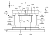
- FIG. 3 is a cross-sectional view showing the structure of the heating support unit.
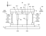
- FIG. 4 is a perspective view showing the structure of the heating support unit.
- FIG. 5 is a cross-sectional view showing the structure of the heating support unit.
- FIG. 6 is a cross-sectional view showing arrangement positions of a plurality of support portions.
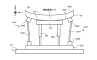
- FIG. 7 is a cross-sectional view showing the state of the heating support unit during a modeling period in which the modeling apparatus forms a modeled object on a workpiece.
- FIG. 8 is a cross-sectional view showing a state of a heating support unit that supports a deformed work.
- FIG. 9 is a cross-sectional view showing a state of a heating support unit that supports a deformed work.
- FIG. 10 is a cross-sectional view showing the state of the heating support unit that supports the deformed work.
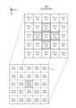
- FIG. 11 is a plan view showing the heating surface of the heating device in the first modified example.
- FIG. 12 is a plan view showing the heating surface of the heating device in the first modified example.
- FIG. 13 is a plan view showing the heating surface of the heating device in the first modified example.
- FIG. 14 is a block diagram showing a heating support unit in the second modified example.
- Each of FIGS. 15(a) to 15(b) is a plan view showing the heating surface of the heating device in the second modified example.
- a modeling system capable of processing a workpiece W, which is an example of an object.
- a modeling apparatus and a modeling method will be described below using a modeling system SYS that performs additional processing based on a laser build-up welding method (LMD: Laser Metal Deposition).
- LMD Laser Metal Deposition
- Additional processing based on the laser build-up welding method is an additional processing of forming a modeled object that is integrated with or separable from the workpiece W by melting the modeling material M supplied to the workpiece W with the modeling light EL (that is, an energy beam having the form of light).
- the modeling system SYS may perform additional processing based on a method different from the laser build-up welding method.
- the modeling system SYS may perform arbitrary processing (for example, removal processing) different from additional processing.
- Laser Overlay Welding includes Direct Metal Deposition, Directed Energy Deposition, Laser Cladding, Laser Engineered Net Shaping, Direct Light Fabrication, Laser Consolidation, Shape Deposition Manufacturing, Wire Feed Laser Deposition, Gas Through Wire, Laser Powder Fusion, Laser Metal Forming, Selective Laser Powder Remelting, Laser Direct It may also be called casting, laser powder deposition, laser additive manufacturing, laser rapid forming.
- each of the X-axis direction and the Y-axis direction is a horizontal direction (that is, a predetermined direction in a horizontal plane), and the Z-axis direction is a vertical direction (that is, a direction orthogonal to the horizontal plane, which is substantially a vertical direction).
- the directions of rotation (in other words, tilt directions) about the X-, Y-, and Z-axes are referred to as the .theta.X direction, the .theta.Y direction, and the .theta.Z direction, respectively.
- the Z-axis direction may be the direction of gravity.
- the XY plane may be set horizontally.
- FIG. 1 is a system configuration diagram showing the system configuration of the modeling system SYS of this embodiment.
- FIG. 2 is a cross-sectional view schematically showing the structure of the modeling system SYS of this embodiment.
- the modeling system SYS is capable of performing additional processing on the workpiece W.
- the modeling system SYS can model a modeled object on the workpiece W by performing additional processing on the workpiece W.
- FIG. Specifically, the modeling system SYS can form a modeled object integrated with (or separable from) the work W by performing additional processing on the work W.
- the additional processing performed on the work W corresponds to the processing of adding to the work W a modeled object integrated with (or separable from) the work W.
- the modeled object in the present embodiment may mean any object modeled by the modeling system SYS.
- the modeling system SYS can model a three-dimensional structure (that is, a three-dimensional structure having dimensions in all three-dimensional directions, in other words, a structure having dimensions in the X-axis direction, the Y-axis direction, and the Z-axis direction).
- the modeling system SYS can perform additional processing on the stage 31 .
- the modeling system SYS can perform additional processing on the object.
- the object placed on the stage 31 may be another three-dimensional structure (that is, an existing structure) modeled by the modeling system SYS.
- FIG. 2 shows an example in which the work W is an existing structure held by the stage 31 . Also, the description will be made below using an example in which the work W is an existing structure held by the stage 31 .
- the work W may be a repairable item with a defect.
- the modeling system SYS may perform repair processing for repairing the item requiring repair by performing additional processing for modeling a modeled object to compensate for the defective portion.
- the additional processing performed by the modeling system SYS may include additional processing of adding a modeled object to the workpiece W to compensate for the defect.
- the modeling system SYS can perform additional processing based on the laser build-up welding method.
- the modeling system SYS can be said to be a 3D printer that models an object using the layered modeling technology.
- the layered manufacturing technology may also be referred to as rapid prototyping, rapid manufacturing, or additive manufacturing.
- the modeling system SYS performs additional processing by processing the modeling material M using the modeling light EL, which is an energy beam.
- the modeling material M is a material that can be melted by irradiation with modeling light EL having a predetermined intensity or higher.
- a modeling material M for example, at least one of a metallic material and a resinous material can be used.
- the modeling material M other materials different from the metallic material and the resinous material may be used.
- the building material M is a powdery or granular material. That is, the modeling material M is a granular material. However, the modeling material M does not have to be granular.
- the modeling material M at least one of a wire-like modeling material and a gaseous modeling material may be used.
- the modeling system SYS includes a material supply source 1, a modeling device 2, a stage device 3, a measuring device 4, a light source 5, a gas supply source 6, and a control device 7, as shown in FIGS.
- the modeling device 2 and the stage device 3 may be housed in a chamber space 83IN inside the housing 8 .
- the material supply source 1 supplies the modeling material M to the modeling device 2 .
- the material supply source 1 supplies a desired amount of the modeling material M according to the required amount so that the required amount of the modeling material M is supplied to the modeling apparatus 2 per unit time for performing additional processing.
- the modeling apparatus 2 processes the modeling material M supplied from the material supply source 1 to model a modeled object.
- the modeling apparatus 2 includes a modeling head 21 and a head drive system 22 to model a modeled object.
- the modeling head 21 includes an irradiation optical system 211 and a material nozzle (that is, a supply system for supplying the modeling material M) 212 . 1 and 2, the modeling head 21 has a single irradiation optical system 211, but the modeling head 21 may have a plurality of irradiation optical systems 211.
- the irradiation optical system 211 is an optical system (for example, a condensing optical system) for emitting the modeling light EL.
- the irradiation optical system 211 is optically connected to the light source 5 that emits the shaping light EL via an optical transmission member 51 such as an optical fiber or a light pipe.
- the irradiation optical system 211 emits shaping light EL propagating from the light source 5 via the light transmission member 51 .
- the irradiation optical system 211 irradiates the shaping light EL from the irradiation optical system 211 downward (that is, to the -Z side).
- a stage 31 is arranged below the irradiation optical system 211 .
- the irradiation optical system 211 irradiates the work W with the emitted modeling light EL.
- the irradiation optical system 211 irradiates the workpiece W with the shaping light EL based on the information on the workpiece W.
- FIG. Specifically, the irradiation optical system 211 can irradiate the shaping light EL onto a target irradiation region EA set on the work W or in the vicinity of the work W as a region irradiated (typically, condensed) with the shaping light EL.
- the state of the irradiation optical system 211 can be switched under the control of the control device 7 between a state in which the target irradiation area EA is irradiated with the shaping light EL and a state in which the target irradiation area EA is not irradiated with the shaping light EL.
- the direction of the shaping light EL emitted from the irradiation optical system 211 is not limited to directly downward (that is, coinciding with the ⁇ Z-axis direction), and may be, for example, a direction inclined by a predetermined angle with respect to the Z-axis.
- the material nozzle 212 supplies (for example, injects, jets, ejects, or sprays) the modeling material M.
- the material nozzle 212 is physically connected to the material supply source 1 which is the supply source of the modeling material M via the supply pipe 11 and the mixing device 12 .
- the material nozzle 212 supplies the modeling material M supplied from the material supply source 1 through the supply pipe 11 and the mixing device 12 .
- the material nozzle 212 may pump the modeling material M supplied from the material supply source 1 through the supply pipe 11 .
- the modeling material M from the material supply source 1 and the gas for transportation may be mixed in the mixing device 12 and then pressure-fed to the material nozzle 212 via the supply pipe 11.
- the material nozzle 212 supplies the modeling material M with the gas for conveyance.
- the carrier gas for example, a purge gas supplied from the gas supply source 6 is used.
- gas supplied from a gas supply source different from the gas supply source 6 may be used as the carrier gas.
- the material nozzle 212 is drawn in the shape of a tube in FIG. 2, the shape of the material nozzle 212 is not limited to this shape.
- the material nozzle 212 supplies the modeling material M downward (that is, to the ⁇ Z side) from the material nozzle 212 .
- a stage 31 is arranged below the material nozzle 212 .
- the material nozzle 212 supplies the modeling material M toward the work W or the vicinity of the work W.
- the traveling direction of the modeling material M supplied from the material nozzle 212 is a direction inclined by a predetermined angle (an acute angle as an example) with respect to the Z-axis direction, but it may be on the -Z side (that is, directly below).
- the material nozzle 212 supplies the modeling material M to the irradiation position of the modeling light EL (that is, the target irradiation area EA irradiated with the modeling light EL from the irradiation optical system 211). For this reason, the material nozzle 212 and the irradiation optical system 211 are aligned so that the target supply area MA set on or near the workpiece W as the area in which the material nozzle 212 supplies the modeling material M matches (or at least partially overlaps) the target irradiation area EA. In this case, the modeling material M supplied from the material nozzle 212 is irradiated with the processing light EL emitted from the irradiation optical system 211 . As a result, the modeling material M melts. That is, a molten pool MP containing the molten modeling material M is formed on the workpiece W. As shown in FIG.
- the material nozzle 212 may supply the modeling material M to the molten pool MP formed by the modeling light EL emitted from the irradiation optical system 211 .
- the material nozzle 212 does not have to supply the modeling material M to the molten pool MP.
- the modeling system SYS may cause the irradiation optical system 211 to melt the modeling material M from the material nozzle 212 before it reaches the workpiece W, and adhere the molten modeling material M to the workpiece W.
- the head drive system 22 moves the modeling head 21 under the control of the control device 7 . That is, the head driving system 22 moves the irradiation optical system 211 and the material nozzle 212 under the control of the control device 7 .
- the head drive system 22 moves the shaping head 21 along at least one of the X-axis, Y-axis, Z-axis, ⁇ X direction, ⁇ Y direction and ⁇ Z direction, for example.
- the head drive system 22 moves the shaping head 21, the relative positions of the shaping head 21 and the stage 31 and the workpiece W placed on the stage 31 change.
- the target irradiation area EA and the target supply area MA furthermore, the molten pool MP
- the modeling material M supplied from the material nozzle 212 is irradiated with the modeling light EL emitted by the irradiation optical system 211 .
- a molten pool MP is formed on the workpiece W.
- the modeling light EL is no longer applied to the molten pool MP as the modeling head 21 moves, the modeling material M melted in the molten pool MP solidifies. That is, a modeled object corresponding to the deposit of the solidified modeling material M is formed.
- the modeling apparatus 2 repeats a series of modeling processes including the formation of the molten pool MP by irradiation of the modeling light EL and the solidification of the molten modeling material M while moving the modeling head 21 along at least one of the X-axis direction and the Y-axis direction. That is, the modeling apparatus 2 repeats a series of modeling processes including the formation of the molten pool MP by the irradiation of the modeling light EL and the solidification of the molten modeling material M while changing the positional relationship between the modeling head 21 and the workpiece W (further, the positional relationship between the modeling head 21 and the modeled object formed on the workpiece W).
- a structural layer corresponding to an aggregate of shaped objects formed in a pattern corresponding to the movement locus of the molten pool MP is formed.
- the modeling apparatus 2 sequentially forms a plurality of structural layers such that the plurality of structural layers are stacked. As a result, a three-dimensional structure corresponding to an assembly of multiple structural layers is additively formed.
- the stage device 3 includes a stage 31 , a stage drive system 32 and a heating support unit 33 .
- a workpiece W is placed on the stage 31 .
- the work W is placed on the stage 31 via the heating support unit 33 .
- the work W is supported by the heating support unit 33 .
- a heating support unit 33 that supports the workpiece W is placed on the stage 31 .
- the stage 31 may be regarded as supporting the work W via the heating support unit 33 .
- the stage 31 may be capable of holding the heating support unit 33 placed on the stage 31 .
- the stage 31 may include at least one of a mechanical chuck, an electrostatic chuck, a vacuum chuck, and the like to hold the heating support unit 33 .
- the stage 31 may not be able to hold the heating support unit 33 placed on the stage 31 .
- the heating support unit 33 may be placed on the stage 31 without clamping.
- the irradiation optical system 211 described above emits the shaping light EL during at least part of the period in which the workpiece W is placed on the stage 31 via the heating support unit 33 .
- the material nozzle 212 described above supplies the modeling material M during at least part of the period in which the workpiece W is placed on the stage 31 via the heating support unit 33 .
- the stage drive system 32 moves the stage 31 .
- the stage drive system 32 moves the stage 31 along at least one of the X-axis, Y-axis, Z-axis, ⁇ X direction, ⁇ Y direction and ⁇ Z direction.
- the stage drive system 32 moves the stage 31, the relative positions of the shaping head 21 and the stage 31 and the workpiece W placed on the stage 31 change.
- the target irradiation area EA and the target supply area MA (furthermore, the molten pool MP) move relative to the workpiece W.
- the heating support unit 33 can support the workpiece W.
- the heating support unit 33 may be capable of holding the workpiece W.
- the heating support unit 33 may include at least one of a mechanical chuck, an electrostatic chuck, a vacuum chuck, and the like to hold the work W.
- the heating support unit 33 may not be able to hold the workpiece W.
- the workpiece W may be clamplessly supported by the heating support unit 33 .
- the irradiation optical system 211 described above emits the shaping light EL during at least part of the period in which the work W is supported by the heating support unit 33 .
- the material nozzle 212 described above supplies the modeling material M during at least part of the period in which the work W is supported by the heating support unit 33 .
- the heating support unit 33 can heat the supported work W in addition to supporting the work W. That is, the heating support unit 33 has a function of supporting the work W and a function of heating the work W. As shown in FIG.
- heating support unit 33 The detailed structure of the heating support unit 33 will be described in detail later with reference to FIGS. 3 to 6.
- the light source 5 emits, for example, at least one of infrared light, visible light, and ultraviolet light as modeling light EL.
- the shaping light EL may contain a plurality of pulsed lights (that is, a plurality of pulsed beams).
- the shaping light EL may include continuous light (CW: Continuous Wave).
- the shaping light EL may be laser light.
- the light source 5 may include a laser light source (for example, a semiconductor laser such as a laser diode (LD: Laser Diode).
- the laser light source may include at least one of a fiber laser, a CO 2 laser, a YAG laser, an excimer laser, and the like.
- the shaping light EL may not be a laser light.
- the light source 5 may be any light source (for example, at least one of an LED (Light Emitting Diode) and a discharge lamp). may contain.
- the gas supply source 6 is a purge gas supply source for purging the chamber space 83 IN inside the housing 8 .
- the purge gas contains inert gas. Examples of inert gas include nitrogen gas and argon gas.
- the gas supply source 6 is connected to the chamber space 83 IN via a supply port 82 formed in the partition member 81 of the housing 8 and a supply pipe 61 connecting the gas supply source 6 and the supply port 82 .
- the gas supply source 6 supplies the purge gas to the chamber space 83IN through the supply pipe 61 and the supply port 82. As shown in FIG. As a result, the chamber space 83IN becomes a space purged with the purge gas.
- the purge gas supplied to the chamber space 83IN may be exhausted from an exhaust port (not shown) formed in the partition member 81 .
- the gas supply source 6 may be a cylinder containing an inert gas.
- the inert gas is nitrogen gas
- the gas supply source 6 may be a nitrogen gas generator that generates nitrogen gas using the atmosphere as a raw material.
- the purge gas supplied from the gas supply source 6 is supplied to the supply port 82 formed in the chamber space 83IN in order to purge the entire chamber space 83IN inside the housing 8.
- the purge gas may be supplied from a supply port (not shown) provided in the shaping head 21 so as to locally fill the space near the irradiation position of the shaping light EL by the irradiation optical system 211 with the purge gas.
- the material nozzle 212 that ejects the purge gas may locally fill the space in the vicinity of the irradiation position of the modeling light EL with the purge gas.
- a supply port for supplying the purge gas may be formed in the material nozzle 212, and the supply port supplied to the material nozzle 212 may locally fill the space in the vicinity of the irradiation position of the modeling light EL with the purge gas.
- the gas supply source 6 may supply the purge gas to the mixing device 12 to which the modeling material M from the material supply source 1 is supplied.
- the gas supply source 6 may be connected to the mixing device 12 via a supply pipe 62 that connects the gas supply source 6 and the mixing device 12 .
- gas source 6 supplies purge gas to mixing device 12 via supply tube 62 .
- the molding material M from the material supply source 1 may be supplied (specifically, pumped) through the supply pipe 11 toward the material nozzle 212 by the purge gas supplied from the gas supply source 6 through the supply pipe 62. That is, the gas supply source 6 may be connected to the material nozzle 212 via the supply pipe 62 , the mixing device 12 and the supply pipe 11 . In this case, the material nozzle 212 will supply the building material M together with the purge gas for pumping the building material M.
- the control device 7 controls the operation of the modeling system SYS.
- the control device 7 may control the modeling device 2 (for example, at least one of the modeling head 21 and the head drive system 22) included in the modeling system SYS so as to perform additional processing on the workpiece W.
- the control device 7 may control the stage device 3 (for example, the stage drive system 32) included in the modeling system SYS so as to perform additional processing on the workpiece W.
- the control device 7 may include, for example, an arithmetic device and a storage device.
- the computing device may include, for example, at least one of a CPU (Central Processing Unit) and a GPU (Graphics Processing Unit).
- a storage device may include, for example, memory.
- the control device 7 functions as a device that controls the operation of the modeling system SYS by the arithmetic device executing a computer program.
- This computer program is a computer program for causing the arithmetic device to perform (that is, to execute) an operation to be performed by the control device 7, which will be described later.
- this computer program is a computer program for causing the control device 7 to function so as to cause the modeling system SYS to perform operations described later.
- the computer program executed by the arithmetic device may be recorded in a storage device (that is, a recording medium) provided in the control device 7, or may be recorded in any storage medium (e.g., hard disk or semiconductor memory) that is built in the control device 7 or externally attached to the control device 7.
- the computing device may download the computer program to be executed from a device external to the control device 7 via the network interface.
- the control device 7 may control the emission mode of the shaping light EL by the irradiation optical system 211 .
- the emission mode may include, for example, at least one of the intensity of the shaping light EL and the emission timing of the shaping light EL.
- the emission mode may include, for example, at least one of the emission time of the pulsed light, the emission period of the pulsed light, and the ratio between the length of the emission time of the pulsed light and the emission period of the pulsed light (so-called duty ratio).
- the control device 7 may control the movement mode of the modeling head 21 by the head drive system 22 .
- the control device 7 may be called a head movement control section that controls movement of the modeling head 21 by the head drive system 22 .
- the control device 7 may control how the stage 31 is moved by the stage drive system 32 .
- the control device 7 may be referred to as a stage movement control section that controls movement of the stage 31 by the stage drive system 32 .
- the movement mode may include, for example, at least one of movement amount, movement speed, movement direction, and movement timing (movement timing).
- the control device 7 may be called a rotation control section that controls the rotation of the stage 31 by the stage drive system 32 .
- the movement mode of the stage 31 may include the rotation mode of the stage 31 .
- the rotation mode may include at least one of rotation amount (for example, rotation angle), rotation speed, rotation direction, and rotation timing (rotation timing).
- rotation amount for example, rotation angle
- rotation speed for example, rotation direction
- rotation timing rotation timing
- the control device 7 may be referred to as a tilt control section that controls the tilt of the stage 31 by the stage drive system 32.
- the movement mode of the stage 31 may include the tilt mode of the stage 31 .
- the tilt mode may include at least one of tilt amount (for example, tilt angle, typically tilt angle with respect to the horizontal XY plane), tilt speed, tilt direction, and tilt timing (tilt timing).
- control device 7 may control the supply mode of the modeling material M by the material nozzle 212 .
- the supply mode may include, for example, at least one of supply amount (especially supply amount per unit time) and supply timing (supply period).
- the control device 7 may control how the workpiece W is heated by the heating support unit 33 .
- the heating mode may include at least one of a heating rate, a heating time, a heating amount (for example, an amount of energy transferred from the heating support unit 33 to the work W to heat the work W), and a heating position.
- the control device 7 does not have to be provided inside the modeling system SYS.
- the control device 7 may be provided as a server or the like outside the modeling system SYS.
- the control device 7 and the modeling system SYS may be connected by a wired and/or wireless network (or data bus and/or communication line).
- a wired network a network using a serial bus interface represented by at least one of IEEE1394, RS-232x, RS-422, RS-423, RS-485 and USB may be used.
- a network using a parallel bus interface may be used as the wired network.
- a network using an Ethernet (registered trademark) interface represented by at least one of 10BASE-T, 100BASE-TX, and 1000BASE-T may be used.
- a network using radio waves may be used as the wireless network.
- An example of a network using radio waves is a network conforming to IEEE802.1x (for example, at least one of wireless LAN and Bluetooth (registered trademark)).
- a network using infrared rays may be used as the wireless network.
- a network using optical communication may be used as the wireless network.
- the control device 7 and the modeling system SYS may be configured to be able to transmit and receive various types of information via a network.
- control device 7 may be capable of transmitting information such as commands and control parameters to the modeling system SYS via a network.
- the modeling system SYS may include a receiving device that receives information such as commands and control parameters from the control device 7 via the network.
- the modeling system SYS may include a transmission device (that is, an output device that outputs information to the control device 7) that transmits information such as commands and control parameters to the control device 7 via the network.
- the first control device that performs part of the processing performed by the control device 7 may be provided inside the modeling system SYS, while the second control device that performs another part of the processing performed by the control device 7 may be provided outside the modeling system SYS.
- a computing model that can be constructed by machine learning may be implemented in the control device 7 by the computing device executing a computer program.
- An example of an arithmetic model that can be constructed by machine learning is an arithmetic model that includes a neural network (so-called artificial intelligence (AI)).
- learning the computational model may include learning neural network parameters (eg, at least one of weights and biases).
- the control device 7 may use the arithmetic model to control the operation of the modeling system SYS.
- the operation of controlling the operation of the modeling system SYS may include the operation of controlling the operation of the modeling system SYS using the arithmetic model.
- control device 7 may be equipped with an arithmetic model that has already been constructed by off-line machine learning using teacher data. Further, the arithmetic model installed in the control device 7 may be updated by online machine learning on the control device 7 .
- control device 7 may control the operation of the modeling system SYS using a computing model implemented in a device external to the control device 7 (that is, a device provided outside the modeling system SYS) in addition to or instead of the computing model implemented in the control device 7.
- the recording medium for recording the computer program executed by the control device 7, at least one of CD-ROM, CD-R, CD-RW, flexible disc, optical disc such as MO, DVD-ROM, DVD-RAM, DVD-R, DVD+R, DVD-RW, DVD+RW and Blu-ray (registered trademark), magnetic medium such as magnetic tape, magneto-optical disc, semiconductor memory such as USB memory, and any other arbitrary medium that can store the program may be used.
- the recording medium may include a device capable of recording a computer program (for example, a general-purpose device or a dedicated device in which the computer program is implemented in at least one form of software, firmware, etc.).
- each process and function included in the computer program may be realized by a logical processing block realized in the control device 7 by the control device 7 (that is, a computer) executing the computer program, or a predetermined gate array (FPGA (Field Programmable Gate Array), ASIC (Application Specific Integrated Circuit)) provided in the control device 7, etc. It may be implemented by hardware, or may be implemented in a form in which logical processing blocks and partial hardware modules that implement some elements of hardware are mixed.
- FPGA Field Programmable Gate Array
- ASIC Application Specific Integrated Circuit
- Heating support unit 33 Next, the heating support unit 33 will be further described.
- FIG. 3 is a sectional view showing the structure of the heating support unit 33.
- FIG. 4 is a perspective view showing the structure of the heating support unit 33. As shown in FIG.
- the heating support unit 33 includes a heating device 331, a temperature sensor 332, a force application device 333, a support device 334, and a cooling device 335.
- the heating device 331 is a device capable of heating the workpiece W.
- the heating device 331 may be any device as long as the work W can be heated.
- the heating device 331 may be a device capable of heating the work W by transferring heat to the work W.
- the heating device 331 may include a heater (for example, a cartridge heater) capable of heating the workpiece W using heat generated in a conductor through which current flows.
- the heating device 331 may include a heater (for example, a cartridge heater) capable of heating the workpiece W using resistance heating.
- the heating device 331 may include a heater (for example, an infrared radiation heater) capable of heating the workpiece W using electromagnetic waves such as infrared rays.
- heating device 331 may include other types of heaters.
- the heating device 331 is arranged below the workpiece W. In this case, the heating device 331 can heat the work W from below. Specifically, the heating device 331 is arranged so as to face the lower surface WSr of the workpiece W. As shown in FIG. The lower surface WSr is a surface facing downward (a surface facing the -Z side in the examples shown in FIGS. 3 and 4). In this case, the heating device 331 can heat the workpiece W via the lower surface WSr of the workpiece W. The heating device 331 can heat the work W by heating the lower surface WSr of the work W. As shown in FIG.
- the heating device 331 does not have to be arranged below the workpiece W.
- the heating device 331 may be arranged at any position as long as the workpiece W can be heated.
- the heating device 331 may be arranged on the side of the workpiece W. That is, the heating device 331 may heat the work W from the side thereof.
- the heating device 331 may be arranged above the workpiece W. That is, the heating device 331 may heat the work W from above.
- the lower surface Wsr of the work W is the surface opposite to the upper surface WSu of the work W.
- the upper surface WSu is a surface facing upward (a surface facing the +Z side in the examples shown in FIGS. 3 and 4).
- the irradiation optical system 211 irradiates the workpiece W with the modeling light EL from above, and the material nozzle 212 supplies the workpiece W with the modeling material M from above. Therefore, the upper surface WSu is a surface to which the modeling light EL is irradiated and the modeling material M is supplied.
- the heating device 331 heats the work W via the lower surface WSr of the work W, the heating device 331 does not adversely affect the irradiation of the modeling light EL and the supply of the modeling material M. That is, the modeling apparatus 2 can appropriately model a modeled object on the work W even when the work W is supported by the heating support unit 33 including the heating device 331 .
- the heating device 331 heats the work W by contacting at least part of the work W. For example, when the heating device 331 can heat the work W from below the work W as described above, the heating device 331 may heat the work W by contacting at least a portion of the lower surface WSr of the work W. For example, when the heating device 331 can heat the work W from the side of the work W as described above, the heating device 331 may heat the work W by contacting at least part of the side surface of the work W. In the following description, for convenience of description, an example in which the work W is heated by the heating device 331 contacting at least a portion of the lower surface WSr of the work W will be described.
- a heating device capable of heating the work W by contacting the work W may be used as the heating device 331 .
- a heating device capable of heating the work W without contacting the work W may be used as the heating device 331 .
- the heating device 331 may heat the work W without contacting the work W.
- the heating device 331 may heat the work W without contacting the work W.
- the surface of the heating device 331 that contacts at least part of the work W may be regarded as functioning as a heating surface 3311 for heating the work W.
- the heating device 331 may have a heating surface 3311 that contacts at least a portion of the workpiece W.
- the heating surface 3311 is typically a surface (in other words, a portion) of the heating device 331 that can transfer heat to the workpiece W.
- the heating surface 3311 may be a surface (in other words, a portion) capable of releasing heat transferred to the work W.
- the heating device 331 may heat the work W via the heating surface 3311 .
- the surface of the heating device 331 that can transmit heat to the work W may be regarded as functioning as the heating surface 3311 for heating the work W.
- the heating device 331 heats the workpiece W by contacting at least a portion of the lower surface WSr of the workpiece W.
- the heating device 331 has a heating surface 3311 that contacts at least part of the lower surface WSr of the workpiece W.
- the heating surface 3311 is typically a surface that faces at least a portion of the lower surface WSr of the workpiece W.
- the heating surface 3311 includes an upward facing surface (which in the example shown in FIGS. 3 and 4 is the surface facing the +Z side and may be referred to as the top surface).
- the heating device 331 may be in contact with at least a portion of the workpiece W via a heat conducting member 3313. That is, between the heating device 331 and the work W, a heat conducting member 3313 may be arranged.
- FIG. 5 shows an example of the heating device 331 that contacts at least a portion of the work W through a heat conducting member 3313.
- the heating surface 3311 which is the upper surface of the heating device 331, contacts at least a portion of the lower surface WSr of the workpiece W, as described above.
- the heating surface 3311 of the heating device 331 may be in contact with at least part of the lower surface WSr of the workpiece W via the heat conducting member 3313 . That is, between at least part of the heating surface 3311 and at least part of the lower surface WSr of the workpiece W, the heat conducting member 3313 may be arranged.
- the heat-conducting member 3313 is a member capable of transmitting heat generated by the heating device 331 to the workpiece W.
- the heating device 331 can heat the workpiece W via the heat conducting member 3313 .
- the heating device 331 can heat the workpiece W in contact with the heat conducting member 3313 by heating the heat conducting member 3313 .
- a heating surface 3311 of the heating device 331 can heat the lower surface WSr of the work W via a heat conducting member 3313 .
- the heating surface 3311 can heat the lower surface WSr of the workpiece W in contact with the heat conducting member 3313 by heating the heat conducting member 3313 .
- the heating device 331 can efficiently heat the work W even when the heating device 331 is not in direct contact with the work W.
- the heating device 331 can be considered to be in thermal contact with at least a part of the work W.
- a state in which the heating device 331 and at least a portion of the work W are in contact may include not only a “state in which the heating device 331 and at least a portion of the work W are in direct contact” but also a “state in which the heating device 331 and at least a portion of the work W are in indirect contact via another member such as the heat conducting member 3313”.
- a state in which the heating device 331 and at least a portion of the work W are in contact may also include a "state in which the heating device 331 and at least a portion of the work W are in thermal contact via another member such as the heat conducting member 3313.”
- the thermally conductive member 3313 may typically be a member having a higher thermal conductivity than the thermal conductivity of the air or the purge gas that fills the chamber space 83IN. In this case, even if a space (for example, a space of air or purge gas) is formed between at least a portion of the heating surface 3311 and at least a portion of the lower surface WSr of the work W, the heating device 331 can efficiently heat the work W via the heat conducting member 3313 as long as the space is filled with the heat conducting member 3313.
- a space for example, a space of air or purge gas
- the heat-conducting member 3313 may be any member as long as it can transmit the heat generated by the heating device 331 to the work W.
- the thermally conductive member 3313 may include at least one of thermally conductive paste and thermally conductive grease.
- thermally conductive grease can be used in a temperature range of -10 degrees to +800 degrees, for example.
- the stage device 3 may be provided with a supply port for supplying a gas capable of forming an airflow for guiding the gas to the recovery port.
- the open space may be used as an opening (space) for the recovery port to recover the gas and a space for the supply port to supply the gas.
- the heat conducting member 3313 may be arranged in a closed space separated from the machining space where the work W exists. In this case, the gas mentioned above is less likely to flow into the processing space.
- the temperature sensor 332 is a temperature detection device capable of detecting the temperature of the workpiece W.
- the temperature sensor 332 may be capable of detecting the temperature of the portion of the work W heated by the heating device 331 .
- the temperature sensor 332 may be capable of detecting the temperature of the lower surface WSr of the work W heated by the heating device 331 .
- the temperature sensor 332 may be capable of detecting the temperature of a portion of the work W to which the modeling apparatus 2 irradiates the modeling light EL.
- the temperature sensor 332 may be any device as long as the temperature of the workpiece W can be detected.
- temperature sensor 332 may include a thermocouple.
- the force applying device 333 is a device capable of applying force acting on the heating device 331 .
- the force applying device 333 is a device capable of applying force to the heating device 331 .
- the force applying device 333 is a device capable of applying a force acting to push the heating device 331 toward the work W to the heating device 331 .
- the force applying device 333 is a device capable of applying a force directed toward the work W from the heating device 331 to the heating device 331 .
- the heating device 331 is arranged below the workpiece W as described above.
- the force application device 333 may apply an upward force to the heating device 331 .
- the force application device 333 may apply a force acting to push the heating device 331 upward from below to the heating device 331 .
- the force applying device 333 may apply a force acting to push the heating device 331 toward the lower surface WSr of the workpiece W.
- the force applying device 333 may apply the force to the heating device 331 from below. That is, the force application device 333 may apply force to the heating device 331 from below the heating device 331 . Specifically, the force application device 333 may apply force to the lower surface 3312 of the heating device 331 . The force applying device 333 may apply a force to the lower surface 3312 of the heating device 331 so as to push the heating device 331 upward from below.
- the lower surface 3312 includes a surface located opposite to the heating surface 3311 , which is the upper surface of the heating device 331 .
- the force application device 333 may apply force to the heating device 331 by contacting the heating device 331 .
- the contact point between the force applying device 333 and the heating device 331 may be regarded as functioning as an action point where the force applied by the force applying device 333 acts on the heating device 331 .
- the force applying device 333 may apply the force to the heating device 331 by contacting the lower surface 3312 of the heating device 331.
- the contact point between the force applying device 333 and the lower surface 3312 of the heating device 331 may be regarded as functioning as an action point at which the force applied by the force applying device 333 acts on the heating device 331 .
- the force application device 333 may apply force to the heating device 331 without contacting the heating device 331 .
- the force applying device 333 may be any device as long as it can apply force to the heating device 331 .
- the force applying device 333 may be a device capable of applying force to the heating device 331 using an elastic member.
- force application device 333 may include an elastic member.
- elastic members include at least one of springs and compression coils.
- the force applying device 333 is supported by a cooling device 335 that can also function as a base member for supporting the force applying device 333 .
- the cooling device 335 may support the force applying device 333 from below the force applying device 333 .
- the force applying device 333 may be located on the cooling device 335 .
- the point at which the cooling device 335 supports the force applying device 333 (that is, the point at which the force applying device 333 and the cooling device 335 contact each other) may be regarded as functioning as a fulcrum that makes the force applying device 333 stationary.
- the force application device 333 may be supported by a support member (for example, the stage 31) different from the cooling device 335.
- the force applying device 333 may have a shape extending from the cooling device 335 that supports the force applying device 333 along the first extending direction (for example, the Z-axis direction in the examples shown in FIGS. 3 and 4) toward the heating device 331 to which the force applying device 333 applies force.
- the force applying device 333 may apply force to the heating device 331 by contacting the heating device 331 via a first end portion 3331 (for example, the +Z side end portion in the example shown in FIG. 3), which is one end of the force applying device 333 in the first stretching direction.
- the force applying device 333 may be supported by the cooling device 335 by being in contact with or connected to the cooling device 335 via a second end portion 3332 (for example, the ⁇ Z side end portion in the examples shown in FIGS. 3 and 4), which is the other end of the force applying device 333 in the first stretching direction.
- the second end portion 3332 is a portion of the force application device 333 located farther from the heating device 331 than the first end portion 3331 in the first stretching direction.
- Second end portion 3332 is the portion of force applicator 333 opposite first end portion 3331 .
- the heating support unit 33 may have a single force applying device 333 .
- the heating support unit 33 may comprise multiple force applying devices 333 .
- the heating support unit 33 comprises four force applying devices 333 .
- the plurality of force applying devices 333 may be arranged so that the force applied from the plurality of force applying devices 333 to the heating device 331 is not locally biased.
- the four force applying devices 333 are arranged at equal intervals in a 2 ⁇ 2 matrix arrangement.
- the force applying device 333 may be regarded as a device capable of applying to the heating device 331 a force acting to push the heating device 331 toward the heat conducting member 3313.
- the force applying device 333 may be regarded as a device capable of applying a force acting in a direction from the heating device 331 toward the heat conducting member 3313 to the heating device 331 . Even in this case, the force applying device 333 can apply a force acting to push the heating device 331 toward the work W to the heating device 331 by applying a force acting to push the heating device 331 toward the heat conducting member 3313.
- the state in which "the force applying device 333 applies a force acting to push the heating device 331 toward the work W to the heating device 331” is not only a state in which "the force applying device 333 applies a force acting to push the heating device 331 toward the work W in a situation where the heat conduction member 3313 is not disposed between the heating device 331 and the work W", but also a state in which "the heating device 331 and the work W are applied to the heating device 331.”
- the force applying device 333 applies a force acting to push the heating device 331 toward the heat conducting member 3313 (and, as a result, push the heating device 331 toward the work W) under the condition that the heat conducting member 3313 is arranged between W and the heating device 331.
- the support device 334 is a device capable of supporting the work W.
- the support device 334 supports the work W from below.
- the support device 334 supports the work W from below via the lower surface WSr of the work W. As shown in FIG.
- the support device 334 supports the work W from below by coming into contact with the lower surface WSr of the work W. As shown in FIG.
- the support device 334 includes a plurality of support members 3340 to support the workpiece W. Each support member 3340 supports the work W from below. Each support member 3340 supports the work W from below via the lower surface WSr of the work W. Each support member 3340 supports the work W from below by coming into contact with the lower surface WSr of the work W.
- the number of support members 3340 included in the support device 334 is set to a number that allows the support device 334 to use a plurality of support members 3340 to stably support the work W.
- the support device 334 may have three or more support members 3340 in order to achieve a state in which the support device 334 can stably support the workpiece W using a plurality of support members 3340 .
- the support device 334 includes four support members 3340 (specifically, a support member 3340#1, a support member 3340#2, a support member 3340#3 and a support member 3340#4). In this case, the support device 334 can stably support the work W using four support members 3340 .
- the support device 334 can stably support the workpiece W using the three support members 3340 . Even if the support device 334 includes five or more support members 3340, the support device 334 can stably support the work W using the five or more support members 3340. FIG. However, an increase in the number of support members 3340 included in the support device 334 may lead to an increase in the cost of the support device 334 . Accordingly, the number of support members 3340 included in the support device 334 may be three or four.
- the plurality of support members 3340 may be arranged so that the support device 334 can stably support the workpiece W using the plurality of support members 3340 .
- the four support members 3340#1 to 3340#4 are arranged in a 2 ⁇ 2 matrix at regular intervals. Furthermore, in the example shown in FIG. 4, the four support members 3340#1 to 3340#4 are arranged at or near the four corners of the workpiece W whose cross section along the XY plane is rectangular.
- Each support member 3340 includes a support portion 3341 , a connection portion 3342 and a connection portion 3343 .
- the supporting portion 3341, the connecting portion 3342 and the connecting portion 3343 included in the supporting member 3340#k are referred to as the supporting portion 3341#k, the connecting portion 3342#k and the connecting portion 3343#k, respectively.
- the support portion 3341 is a member for supporting the work W from below. Specifically, the support portion 3341 is connected to the work W via a connection portion 3342 that contacts the work W (for example, the lower surface WSr of the work W). As a result, the support portion 3341 supports the workpiece W via the connection portion 3342 .
- the weight of the work W is added to the support portion 3341 that supports the work W.
- the strength of the support portion 3341 may be such that the weight of the work W does not cause the support portion 3341 to deform or buckle.
- the rigidity of the support portion 3341 may be such that the weight of the work W does not cause the support portion 3341 to deform or buckle.
- the connecting portion 3342 that contacts the work W holds the work W.
- the connecting portion 3342 may include at least one of a mechanical chuck, an electrostatic chuck, a vacuum chuck, and the like to hold the work W.
- the connecting portion 3342 may not be able to hold the workpiece W.
- the support part 3341 is supported by a cooling device 335 that can also function as a base member for supporting the support part 3341 .
- the support portion 3341 is connected to the cooling device 335 via a connecting portion 3343 that contacts the cooling device 335 .
- the cooling device 335 may support the support portion 3341 from below the support portion 3341 .
- the cooling device 335 can support the support member 3340 from below the support member 3340 including the support portion 3341 .
- support member 3340 may be considered to be located on cooling device 335 .
- the support portion 3341 may have a shape extending from the cooling device 335 that supports the support portion 3341 along the second extension direction (for example, the Z-axis direction in the examples shown in FIGS. 3 and 4) toward the work W supported by the support portion 3341.
- the support portion 3341 may be able to support the work W by contacting the work W via a connection portion 3342 that is one end of the support member 3340 in the second extending direction (particularly, via an upper part of the connection portion 3342 facing upward).
- the support portion 3341 may be supported by the cooling device 335 by coming into contact with the cooling device 335 via a connection portion 3343 (for example, the end portion on the -Z side in the examples shown in FIGS.
- connection portion 3343 is a portion positioned farther from the work W than the connection portion 3342 (especially, the upper portion of the connection portion 3342 that contacts the work W) in the second extending direction.
- the connection portion 3343 is a portion located on the opposite side of the support portion 3341 from the connection portion 3342 (in particular, the upper portion of the connection portion 3342 that contacts the work W).
- the support part 3341 may be a member that satisfies a predetermined rigidity condition.
- the stiffness condition may include a condition that the stiffness of the support portion 3341 in the first stiffness direction is lower than the stiffness of the support portion 3341 in the second stiffness direction.
- the second rigid direction may be a direction intersecting the first rigid direction.
- the second rigid direction may be a direction that intersects a plane including a plurality of connecting portions 3342 provided on each of the plurality of supporting members 3340 .
- the plane including the connecting portions 3342#1 to 3342#4 is a plane along the XY plane. Therefore, the second rigid direction may be a direction that intersects the XY plane (for example, the Z-axis direction).
- the first rigid direction may be a direction along the XY plane.
- the support portion 3341 that satisfies the rigidity condition described above may satisfy the size condition that the size in the first rigidity direction (for example, the direction along the XY plane) is smaller than the size in the second rigidity direction (for example, the Z-axis direction). Conversely, the supporting portion 3341 that satisfies the size condition is more likely to satisfy the rigidity condition described above than the supporting portion 3341 that does not satisfy the size condition. This is because the smaller the size of the object in one direction, the lower the stiffness of the object in that one direction.
- a plate spring which is a thin plate member, is an example of the support portion 3341 that satisfies such rigidity and size conditions.
- the support portion 3341 is a leaf spring
- the supporting portion 3341 is not limited to the leaf spring.
- the support portion 3341 may include a member other than the leaf spring.
- a leaf spring is a type of elastic body. Therefore, the support portion 3341 may include an elastic body different from the leaf spring.
- the support portion 3341 may include an elastic body that satisfies the rigidity conditions described above.
- the support portion 3341 may include an elastic body that satisfies the size conditions described above.
- a leaf spring typically has a characteristic that the rigidity of the leaf spring in the thickness direction is lower than the rigidity of the leaf spring in each of the width direction and the length direction. Therefore, when the support portion 3341 is a leaf spring, the thickness direction of the leaf spring may be used as the above-described first rigidity direction, and either the width direction or the length direction of the leaf spring may be used as the above-described second rigidity direction.
- the length direction of the leaf spring may mean the longitudinal direction of the leaf spring (that is, the direction in which the leaf spring is stretched).
- the support portion 3341 which is a leaf spring, extends along the Z-axis direction (that is, the second extending direction extending from the cooling device 335 supporting the support portion 3341 toward the work W supported by the support portion 3341). Therefore, in the examples shown in FIGS. 3 and 4, the length direction of the leaf spring is the Z-axis direction. That is, in the examples shown in FIGS. 3 and 4, the longitudinal direction of the plate spring is used as the second rigidity direction.
- the width direction of the leaf spring may mean the direction of the larger size in the cross section of the leaf spring that intersects the longitudinal direction of the leaf spring.
- the thickness direction of the leaf spring may mean the direction of the smaller size in the cross section of the leaf spring that intersects the longitudinal direction of the leaf spring.
- the plurality of support portions 3341 may be arranged so that the thickness direction (that is, the first rigidity direction) of the plate springs forming each support portion 3341 satisfies the predetermined direction condition shown in FIG.
- the directional conditions will be described below with reference to FIG.
- FIG. 6 is a cross-sectional view showing the arrangement positions of the plurality of support portions 3341. As shown in FIG.
- the direction condition may include a first condition that the thickness direction (that is, the first rigidity direction) of the leaf springs forming each support portion 3341 is the direction from the center C1 of the lower surface WSr of the work W toward the connection portion 3342 for connecting each support portion 3341 to the work W.
- the first condition may include the condition that the thickness direction (that is, the first rigidity direction) of the leaf spring that constitutes the support portion 3341#1 is the direction from the center C1 toward the connection portion 3342#1 (specifically, the direction from the center C1 toward the -Y side).
- the first condition may include the condition that the thickness direction (that is, the first rigidity direction) of the leaf spring that constitutes the support portion 3341#2 is the direction from the center C1 toward the connection portion 3342#2 (specifically, the direction from the center C1 toward the +X side).
- the first condition may include a condition that the thickness direction (that is, the first rigidity direction) of the leaf spring that constitutes the support portion 3341#3 is the direction from the center C1 toward the connection portion 3342#3 (specifically, the direction toward the +Y side from the center C1).
- the first condition may include the condition that the thickness direction (that is, the first rigidity direction) of the leaf spring that constitutes the support portion 3341#4 is the direction from the center C1 toward the connection portion 3342#4 (specifically, the direction from the center C1 toward the ⁇ X side).
- the direction condition may include a second condition that the thickness direction (i.e., the first rigidity direction) of the leaf springs forming each support portion 3341 is the direction from the center of gravity C2 of the polygon PS connecting the plurality of connection portions 3342 of the support device 334 toward the connection portion 3342 for connecting each support portion 3341 to the workpiece W.
- the second condition may include a condition that the thickness direction (that is, the first rigidity direction) of the leaf spring that constitutes the support portion 3341#1 is the direction from the center of gravity C2 toward the connecting portion 3342#1 (specifically, the direction from the center of gravity C2 toward the -Y side).
- the second condition may include the condition that the thickness direction (that is, the first rigidity direction) of the leaf spring that constitutes the support portion 3341#2 is the direction from the center of gravity C2 toward the connecting portion 3342#2 (specifically, the direction toward the +X side from the center of gravity C2).
- the second condition may include a condition that the thickness direction (that is, the first rigidity direction) of the leaf spring that constitutes the support portion 3341#3 is the direction from the center of gravity C2 toward the connecting portion 3342#3 (specifically, the direction toward the +Y side from the center of gravity C2).
- the second condition may include the condition that the thickness direction (that is, the first rigidity direction) of the leaf spring that constitutes the support portion 3341#4 is the direction from the center of gravity C2 toward the connection portion 3342#4 (specifically, the direction from the center of gravity C2 toward the -X side).
- FIG. 6 shows an example in which the polygon PS has an outer shape smaller than the outer shape of the work W, and the center C1 coincides with the center of gravity C2.
- the polygon PS does not have to be smaller than the outer shape of the workpiece W, and the center C1 does not have to coincide with the center of gravity C2.
- the direction condition may include a second condition that the thickness direction (i.e., the first rigidity direction) of the plate springs forming each support portion 3341 is the direction from a predetermined point C3 within a polygon PS connecting a plurality of connection portions 3342 of the support device 334 toward the connection portion 3342 for connecting each support portion 3341 to the workpiece W.
- the second condition may include a condition that the thickness direction (that is, the first rigidity direction) of the leaf spring that constitutes the support portion 3341#1 is the direction from the point C3 to the connection portion 3342#1 (specifically, the direction from the point C3 to the -Y side).
- the second condition may include a condition that the thickness direction (that is, the first rigidity direction) of the leaf spring that constitutes the support portion 3341#2 is the direction from the point C3 toward the connection portion 3342#2 (specifically, the direction toward the +X side from the point C3).
- the second condition may include the condition that the thickness direction (that is, the first rigidity direction) of the leaf spring that constitutes the support portion 3341#3 is the direction from the point C3 toward the connection portion 3342#3 (specifically, the direction toward the +Y side from the point C3).
- the second condition may include a condition that the thickness direction (that is, the first rigidity direction) of the leaf spring that constitutes the support portion 3341#4 is the direction from the point C3 to the connection portion 3342#4 (specifically, the direction from the point C3 to the ⁇ X side).
- the heating device 331 described above may typically be arranged inside the polygon PS, as shown in FIG. However, at least part of the heating device 331 may be arranged outside the polygon PS.
- the cooling device 335 is a device capable of cooling an object to be cooled.
- the cooling device 335 may include an air cooling device capable of cooling the object to be cooled by using gas as a coolant.
- the cooling device 335 may include a water cooling device that can cool the object to be cooled by using liquid as a coolant.
- the cooling device 335 may include a chiller capable of cooling the object to be cooled by circulating a coolant including at least one of gas and liquid.
- the object to be cooled may include the force application device 333.
- the cooling device 335 may cool the force applying device 333 .
- the force applying device 333 is supported by the cooling device 335 by contacting the cooling device 335 via the second end portion 3332 of the force applying device 333 (for example, the ⁇ Z side end portion in the examples shown in FIGS. 3 and 4).
- cooling device 335 may cool force applying device 333 via second end portion 3332 .
- Cooling device 335 may cool force applying device 333 by cooling second end portion 3332 .
- the object to be cooled may include the support device 334.
- cooling device 335 may cool support device 334 .
- the support device 334 is supported by the cooling device 335 by coming into contact with the cooling device 335 via the connecting portion 3343 .
- cooling device 335 may cool support device 334 via connection 3343 .
- the cooling device 335 may cool the support device 334 by cooling the connecting portion 3343 .
- the heat from the work W (typically heat -supported unit 33 to the work W) is transmitted to the second end part 3332 via the support device 334, but the cross -sectional area of each support unit 3334 (the intersection of the support unit 3331) is small. Since the heat resistance of the support device 334 is increased, the amount of heat transmitted to the second end 3332 is small. Therefore, cooling can be efficiently performed by the cooling device 335 .
- the cooling device 335 may be placed on the stage 31 .
- the cooling device 335 may cool the stage 31 . That is, the object to be cooled may have the stage 31 .
- FIG. 7 is a cross-sectional view showing the state of the heating support unit 33 during the modeling period in which the modeling apparatus 2 forms a modeled object on the workpiece W. As shown in FIG.
- the modeling apparatus 2 irradiates the workpiece W with the modeling light EL during at least part of the modeling period in which the modeling apparatus 2 forms a modeled object on the workpiece W.
- the modeling apparatus 2 shapes a plurality of structural layers in order to form a three-dimensional structure corresponding to an assembly of the plurality of structural layers as a modeled object
- the modeling apparatus 2 irradiates the workpiece W with the modeling light EL when modeling the first structural layer constituting the three-dimensional structure.
- the modeling apparatus 2 irradiates the upper surface WSu of the workpiece W with the modeling light EL.
- the upper surface WSu of the workpiece W is heated by the shaping light EL.
- the modeling apparatus 2 when the modeling apparatus 2 models another structural layer on top of one structural layer that constitutes a three-dimensional structure, the modeling apparatus 2 irradiates the one structural layer with the modeling light EL. As a result, heat transferred from the shaping light EL to one structural layer may be transferred to the workpiece W via the one structural layer. As a result, the upper surface WSu of the workpiece W is heated by the shaping light EL.
- the temperature of the upper surface WSu of the workpiece W heated by the shaping light EL may be significantly different from the temperature of the lower surface WSr of the workpiece W that is not heated by the shaping light EL. That is, a relatively large temperature gradient may occur between the upper surface WSu of the workpiece W heated by the shaping light EL and the lower surface WSr of the workpiece W not heated by the shaping light EL. As a result, the work W may be deformed. For example, there is a possibility that the workpiece W will be warped and deformed.
- the heating device 331 heats the lower surface WSr of the workpiece W under the control of the control device 7. Specifically, the heating device 331 heats the lower surface WSr of the work W so that the difference between the temperature of the upper surface WSu of the work W and the temperature of the lower surface WSr of the work W becomes smaller (that is, the temperature gradient becomes gentler) than when the heating device 331 does not heat the lower surface WSr of the work W. As a result, compared to the case where the heating device 331 does not heat the lower surface WSr of the work W, the possibility of deformation of the work W is reduced. Therefore, the heating support unit 33 can suppress deformation of the work W by heating the lower surface WSr of the work W during at least part of the modeling period.
- the control device 7 may control the heating device 331 based on the temperature of the work W detected by the temperature sensor 332 .
- the control device 7 may control the heating device 331 based on the temperature of the upper surface WSu of the work W detected by the temperature sensor 332 and the temperature of the lower surface WSr of the work W detected by the temperature sensor 332.
- the control device 7 may control the heating device 331 so that the difference between the temperature of the lower surface WSr of the work W detected by the temperature sensor 332 and the target temperature becomes small.
- the target temperature may be the temperature of the upper surface WSu of the workpiece W expected when the modeling apparatus 2 irradiates the upper surface WSu of the workpiece W with the modeling light EL.
- An example of the target temperature is several hundred degrees (for example, 600 degrees).
- the force applying device 333 may apply a force acting to push the heating device 331 toward the workpiece W to the heating device 331.
- the heating device 331 is less likely to come out of contact with the workpiece W compared to the case where the force applying device 333 does not apply force.
- the possibility of the heating surface 3311 coming out of contact with the workpiece W is reduced.
- the heating device 331 is more likely to come into close contact with at least a portion of the work W compared to when the force applying device 333 does not apply force.
- the possibility that the heating surface 3311 is in close contact with at least a portion of the lower surface WSr of the workpiece W increases. Therefore, when the force applying device 333 applies force, the contact area between the heating surface 3311 and the lower surface WSr of the work W is more likely to increase than when the force applying device 333 does not apply force. In other words, the area of the surface portion of the heating surface 3311 that contacts the lower surface WSr of the workpiece W is likely to increase.
- the heating surface 3311 is more likely to be in close contact with at least a portion of the lower surface WSr of the work W, when the force applying device 333 applies force, the difference between the shape of the heating surface 3311 and the lower surface WSr of the work W at the boundary between the heating surface 3311 and the lower surface WSr of the work W becomes smaller than when the force applying device 333 does not apply the force.
- the larger the contact area between the heating surface 3311 and the lower surface WSr of the workpiece W and/or the smaller the difference between the shape of the heating surface 3311 and the lower surface WSr of the workpiece W the greater the amount of heat transferred from the heating surface 3311 to the lower surface WSr of the workpiece W per unit time.
- the force applying device 333 applies force
- the amount of heat transferred from the heating surface 3311 to the lower surface WSr of the work W per unit time is greater than when the force applying device 333 does not apply force.
- the heating device 331 can heat the workpiece W more efficiently than when the force applying device 333 does not apply force.
- the heat conducting member 3313 is arranged between the heating device 331 and the work W.
- the heating surface 3311 is more likely to come into close contact with at least part of the heat conducting member 3313 compared to when the force applying device 333 does not apply force.
- the heat conducting member 3313 is more likely to come into close contact with the lower surface WSr of the workpiece W. Therefore, when the force applying device 333 applies force, the contact area between the heat conducting member 3313 and the lower surface WSr of the work W is more likely to increase than when the force applying device 333 does not apply force.
- the heat conducting member 3313 is more likely to be in close contact with at least a portion of the lower surface WSr of the work W, when the force applying device 333 applies force, the difference between the shape of the heat conducting member 3313 and the shape of the lower surface WSr of the work W at the boundary between the heat conducting member 3313 and the lower surface WSr of the work W becomes smaller than when the force applying device 333 does not apply force.
- the force applying device 333 applies an excessively large force to the heating device 331, the work W may separate from the support member 3340 that supports the work W (in particular, the connection portion 3342 that contacts and holds the work W). As a result, a technical problem that the support device 334 cannot support the work W may occur. Therefore, in order to solve such a technical problem, the force with which the support device 334 supports the work W (for example, the force with which the connecting portion 3342 holds the work W) may be stronger than the force applied by the force applying device 333 to the heating device 331. In this case, the support device 334 can appropriately support the workpiece W even when the force application device 333 applies force to the heating device 331 .
- the workpiece W is fixed by the support device 334 even when the force application device 333 applies force to the heating device 331 .
- the force applied by the force applying device 333 to the heating device 331 does not cause the workpiece W to move upward.
- the force application device 333 applies force to the heating device 331 while the heating device 331 is heating the lower surface WSr of the workpiece W
- the heat generated by the heating device 331 may be transmitted to the force application device 333 that applies force to the heating device 331.
- force applicator 333 may be thermally affected.
- the force applicator 333 can be deformed by heat.
- the cooling device 335 cools the force applying device 333 . Therefore, compared to the case where the cooling device 335 does not cool the force applying device 333, the force applying device 333 is less likely to be affected by heat. Therefore, the force applying device 333 can appropriately apply force to the work W without being affected by the heat generated by the heating device 331 .
- the force applying device 333 can appropriately apply force to the workpiece W while the influence of the heat generated by the heating device 331 is reduced.
- the heat generated by the heating device 331 may be transmitted to the support device 334 that supports the work W through the work W.
- the support device 334 may be thermally affected.
- support device 334 can be deformed by heat.
- the cooling device 335 cools the support device 334 . Therefore, the support device 334 is less likely to be affected by heat than if the cooling device 335 did not cool the support device 334 . Therefore, the support device 334 can appropriately support the work W without being affected by the heat generated by the heating device 331 .
- the support device 334 can appropriately support the work W while the influence of the heat generated by the heating device 331 is reduced.
- each support portion 3331 of the support device 334 (the cross-sectional area of the plane intersecting with the longitudinal direction of the support portion 3331) is reduced to increase the thermal resistance of the support device 334, the amount of heat transferred from the heated work W to the support device 334 is reduced. can be approximated to uniformity.
- the cooling device 335 since the cooling device 335 is placed on the stage 31 and supports the force application device 333 and the support device 334, the heat generated by the heating device 331 is less likely to be transmitted to the stage 31 via the force application device 333 and the support device 334.
- the cooling device 335 may be regarded as functioning as a heat insulating device that suppresses the heat generated by the heating device 331 from being transferred to the stage 31 . Therefore, the stage 31 can support the work W without being affected by the heat generated by the heating device 331 . For example, the stage 31 can support the work W without being deformed due to heat generated by the heating device 331 .
- the heat generated by the heating device 331 is less likely to be transmitted to the stage 31 , the heat generated by the heating device 331 is less likely to be transmitted to the device positioned below the stage 31 . Therefore, the devices positioned below the stage 31 can operate properly without being affected by the heat generated by the heating device 331 .
- the stage drive system 32 is arranged below the stage 31 , the heat generated by the heating device 331 is less likely to be transmitted to the stage drive system 32 . Therefore, the stage driving system 32 can appropriately move the stage 31 without being affected by the heat generated by the heating device 331 .
- the heating device 331 heats the lower surface WSr of the work W as described above, the work W is less likely to be deformed, but the work W may be deformed in some cases.
- the force applying device 333 does not apply a force acting to push the heating device 331 toward the work W to the heating device 331, a gap may be formed between the lower surface WSr of the deforming work W and the heating surface 3311, as shown in FIG. That is, the shape of the deformed lower surface WSr of the workpiece W may differ from the shape of the heating surface 3311 .
- the heating device 331 may not be able to heat the work W efficiently.
- the force applying device 333 can apply a force to the heating device 331 to push the heating device 331 toward the work W, as described above, even when the work W is deformed.
- the force applying device 333 can deform the heating device 331 (in particular, the heating surface 3311) according to the deformed work W by using the force applied to the heating device 331.
- the force applying device 333 can move the heating device 331 (especially the heating surface 3311) upward when the workpiece W moves upward due to deformation. More specifically, as shown in FIG.
- the force applying device 333 can move upward at least a portion of the heating surface 3311 that faces the at least a portion of the upwardly moved lower surface WSr. Therefore, even when the work W is deformed, when the force applying device 333 applies force, the contact area between the heating surface 3311 and the lower surface WSr of the work W is more likely to increase than when the force applying device 333 does not apply the force.
- the heating device 331 can efficiently heat the work W even when the work W is deformed.
- the heating device 331 (especially the heating surface 3311) may be moved downward. More specifically, when at least a portion of the lower surface WSr of the work W moves downward due to deformation, at least a portion of the heating surface 3311 facing the at least a portion of the lower surface WSr that has moved downward may move downward.
- the force applied by the force applying device 333 to the heating device 331 may be a force that enables the heating device 331 (in particular, the heating surface 3311) to move downward when the workpiece W moves downward.
- the force applied by the force applying device 333 to the heating device 331 may be of a magnitude capable of achieving a state in which at least a portion of the heating surface 3311 facing at least a portion of the lower surface WSr that has moved downward moves downward when at least a portion of the lower surface WSr of the workpiece W moves downward.
- the heat conducting member 3313 is arranged between the heating device 331 and the work W.
- the contact area between the heat conducting member 3313 and the lower surface WSr of the work W is more likely to increase than when the force applying device 333 is not applying force.
- the difference between the shape of the heat conduction member 3313 and the shape of the lower surface WSr of the work W becomes smaller than when the force applying device 333 does not apply force. Therefore, the heating device 331 can efficiently heat the work W even when the work W is deformed.
- the support part 3341 when the support part 3341 satisfies the rigidity condition as described above, the support part 3341 can continue to support the deformed workpiece W appropriately.
- the rigidity condition is that the rigidity of the support portion 3341 in the first rigidity direction (for example, the thickness direction of the leaf spring, which is along the XY plane in FIG. 9) is lower than the rigidity of the support portion 3341 in the second rigidity direction (for example, the length direction of the leaf spring, which is the Z-axis direction in FIG. 9).
- the support portion 3341 is more likely to deform such that at least a portion of the support portion 3341 is displaced along the direction along the XY plane in accordance with the deformation of the workpiece W.
- the connecting part 3342 that connects the support part 3341 to the work W can follow the deformed work W because the support part 3341 is deformed. Therefore, the support portion 3341 can continue to support the deformed workpiece W.
- the rigidity of the support portion 3341 in the second rigidity direction (the Z-axis direction in FIG. 9) is relatively high, even if the work W is deformed, the support portion 3341 is less likely to buckle due to the weight of the work W. Therefore, the support portion 3341 can continue to support the deformed workpiece W appropriately.
- the rigidity of the single support member is relatively high when the support device 334 including the plurality of support portions 3341 is viewed as a single support member.
- the rigidity of the single support member is relatively high in the direction crossing the direction in which the plurality of support portions 3341 extend (for example, the length direction of the plate spring, which is the Z-axis direction in FIG. 9).
- the stiffness of the single support member in the direction along the XY plane is relatively high.
- each support portion 3341 has a characteristic that the rigidity in the thickness direction of the plate spring (the direction along the XY plane in the example shown in FIG. 9) is relatively low.
- the direction in which the rigidity of one support portion 3341 is relatively low intersects the direction in which the rigidity of another support portion 3341 different from the one support portion 3341 is relatively low.
- the direction in which the rigidity of support portions 3341#1 and 3341#3 is relatively low (Y-axis direction) intersects the direction in which the rigidity of support portions 3341#2 and 3341#4 is relatively low (X-axis direction).
- the support device 334 including the support portions 3341#1 to 3341#4 when the support device 334 including the support portions 3341#1 to 3341#4 is viewed as a single member, the rigidity in the X-axis direction of the single member is ensured to be relatively high by the support portions 3341#1 and 3342#3, and the rigidity in the Y-axis direction of the single member is ensured to be relatively high by the support portions 3341#2 and 3342#4. That is, when the support device 334 including the plurality of support portions 3341 is viewed as a single member, the rigidity of the single member is relatively high. As a result, the support portion 3341 can support the workpiece W appropriately.
- FIG. 10 shows the state of the heating support unit 33 when the stage 31 is rotated 90 degrees around the X axis.
- the direction condition is not satisfied, there is a possibility that all the directions in which the rigidity of the plurality of support portions 3341 becomes low match the direction of gravity. As a result, all of the plurality of support portions 3341 are deformed by gravity, and there is a possibility that the support device 334 will not be able to support the workpiece W appropriately.
- the direction condition is satisfied, there is a high possibility that the direction in which the rigidity of at least one of the plurality of support portions 3341 is low does not match the direction of gravity.
- the support device 334 can appropriately support the workpiece W while reducing the influence of gravity.
- the control device 7 may control the heating mode of the workpiece W by the heating support unit 33 based on the distance from the upper surface of the workpiece W to the uppermost structural layer modeled on the workpiece W.
- the distance from the upper surface of the work W to the top structural layer formed on the work W may indicate the height to the top structural layer formed on the work W (that is, the distance in the Z-axis direction).
- a modeling system SYSa in the first modified example differs from the modeling system SYS described above in that it includes a stage device 3 a instead of the stage device 3 .
- Other features of the modeling system SYSa may be the same as other features of the modeling system SYS.
- the stage device 3a differs from the stage device 3 in that it includes a heating support unit 33a instead of the heating support unit 33.
- FIG. Other features of stage device 3 a may be the same as other features of stage device 3 .
- the heating support unit 33a differs from the heating support unit 33 in that the heating device 331 is replaced with a heating device 331a.
- Other features of the heating support unit 33 a may be the same as other features of the heating support unit 33 . Therefore, the heating device 331a in the first modified example will be described below with reference to FIG.
- FIG. 11 is a plan view showing a heating surface 3311a of a heating device 331a in the first modified example.
- the heating device 331a differs from the heating device 331 having a single heating surface 3311 in that it has multiple heating surfaces 3311a.
- the heating device 331a includes 25 heating surfaces 3311a (specifically, heating surfaces 3311a#1 to 3311a#25).
- the number of heating surfaces 3311a is not limited to the number shown in FIG.
- Other features of the heating device 331 a may be the same as other features of the heating device 331 .
- At least two of the plurality of heating surfaces 3311a may be surfaces physically separated from each other. That is, at least two of the plurality of heating surfaces 3311a may be surfaces that are physically distinguishable from each other. At least two of the plurality of heating surfaces 3311a may be surfaces that are physically integrated with each other. That is, one surface portion of a certain single heating surface may be used as one heating surface 3311a, and another surface portion different from the one surface portion of the same single heating surface may be used as the other heating surface 3311a.
- Each heating surface 3311a can heat the workpiece W. Specifically, each heating surface 3311a can heat a lower surface portion Wr of the lower surface WSr of the workpiece W corresponding to each heating surface 3311a.
- the lower surface portion Wr of the lower surface WSr of the workpiece W corresponding to each heating surface 3311a typically includes at least a portion of the surface portion of the lower surface WSr of the workpiece W facing each heating surface 3311a.
- the heating surface 3311a#k (where k is a variable representing an integer between 1 and 25) can heat the lower surface portion Wr#k of the lower surface WSr corresponding to the heating surface 3311a#k.
- the lower surface portion Wr#k that can be heated by the heating surface 3311a#k may at least partially overlap with the lower surface portion Wr#m that can be heated by a different heating surface 3311a#m (m is a variable that is 1 or more and 25 or less and represents an integer different from the variable k). In this case, it may be considered that the heating surface 3311a#k can heat at least part of the lower surface portion Wr#m in addition to the lower surface portion Wr#k. Heating surface 3311a#k may be considered to include at least a portion of heating surface 3311a#m.
- At least a portion of the lower surface portion Wr#13 that can be heated by the heating surface 3311a#13 may at least partially overlap with at least a portion of the lower surface portion Wr#8 that is adjacent to the heating surface 3311a#13 and can be heated by the heating surface 3311a#8.
- the heating surface 3311a#13 can heat at least part of the lower surface portion Wr#8 in addition to the lower surface portion Wr#13.
- the heating surface 3311a#13 includes at least part of the heating surface 3311a#8.
- the lower surface portion Wr#k that can be heated by the heating surface 3311a#k does not have to overlap the lower surface portion Wr#m that can be heated by the heating surface 3311a#m.
- the heating surface 3311a#k may not be able to heat the lower surface portion Wr#m different from the lower surface portion Wr#k.
- the control device 7 may individually control the temperatures of the plurality of heating surfaces 3311a.
- the control device 7 may control the temperature of the heating surface 3311a#k (one heating surface 3311a of the plurality of heating surfaces 3311a) separately and independently from the temperature of the heating surface 3311a#m different from the heating surface 3311a#k (i.e., another heating surface 3311a different from the one heating surface 3311a of the plurality of heating surfaces 3311a).
- control device 7 may individually control the temperatures of the plurality of heating surfaces 3311a so that the difference between the temperature of the upper surface WSu of the workpiece W and the temperature of the lower surface WSr of the workpiece W is smaller (that is, the temperature gradient is gentler) than when the heating device 331a does not heat the lower surface WSr of the workpiece W.
- the temperature of each heating surface 3311a depends on the amount of heat generated by each heating surface 3311a. Therefore, the operation of controlling the temperature of each heating surface 3311a may be considered equivalent to the operation of controlling the amount of heat generated by each heating surface 3311a. Also, the temperature of the heating surface 3311a that heats the workpiece W (that is, generates heat) is usually different from the temperature of the heating surface 3311a that does not heat the workpiece W (that is, does not generate heat). Therefore, the operation of controlling the temperature of each heating surface 3311a may include an operation of switching the state of each heating surface 3311a between the heating state and the heating stop state.
- the heating state may mean a state in which each heating surface 3311a is heating the workpiece W. As shown in FIG.
- the heating stop state may mean a state in which each heating surface 3311a does not heat the workpiece W. As shown in FIG.
- the control device 7 may individually control the amount of heat transferred from the plurality of heating surfaces 3311a to the workpiece W per unit time. For example, the control device 7 may control the amount of heat transferred per unit time from the heating surface 3311a#k to the workpiece W (particularly the lower surface portion Wr#k) separately from the amount of heat transferred per unit time from the heating surface 3311a#m to the workpiece W (particularly the lower surface portion Wr#m).
- control device 7 may individually control the amount of heat transferred from the plurality of heating surfaces 3311a to the work W per unit time so that the difference between the temperature of the upper surface WSu of the work W and the temperature of the lower surface WSr of the work W becomes smaller (that is, the temperature gradient becomes gentler) than when the heating device 331a does not heat the lower surface WSr of the work W.
- the control device 7 may be regarded as controlling the distribution of the heating amount of the work W by the heating device 311 .
- the operation of controlling the temperature of each heating surface 3311a may be considered equivalent to the operation of controlling the distribution of the amount of heating of the work W by the heating device 311 .
- the control device 7 may control the heating device 331 so that the distribution of the heating amount of the work W by the heating device 311 becomes the desired first distribution.
- the desired first distribution may be a distribution that can realize a state in which the difference between the temperature of the upper surface WSu of the workpiece W and the temperature of the lower surface WSr of the workpiece W is smaller than when the heating device 331a does not heat the lower surface WSr of the workpiece W.
- the control device 7 may be regarded as controlling the temperature distribution of the workpiece W.
- FIG. The operation of controlling the temperature of each heating surface 3311a may be considered equivalent to the operation of controlling the temperature distribution of the workpiece W.
- the control device 7 may control the heating device 331 so that the temperature distribution of the work W becomes the desired second distribution.
- the desired second distribution may be a distribution capable of realizing a state in which the difference between the temperature of the upper surface WSu of the workpiece W and the temperature of the lower surface WSr of the workpiece W is smaller than when the heating device 331a does not heat the lower surface WSr of the workpiece W.
- the control device 7 controls the heating device 331a so that the temperature of the heating surface 3311a#k (that is, one heating surface 3311a of the plurality of heating surfaces 3311a) and the temperature of the heating surface 3311a#m (that is, another heating surface 3311a that is different from the one heating surface 3311a of the plurality of heating surfaces 3311a) are different temperatures.
- the control device 7 may control the heating device 331a such that the temperature of the heating surface 3311a#k and the temperature of the heating surface 3311a#m are different at the same time.
- the control device 7 may control the heating device 331a such that the temperature of the heating surface 3311a#k at a certain time is different from the temperature of the heating surface 3311a#m at the same time.
- control device 7 may control the heating device 331a such that the amount of heat transferred from the heating surface 3311a#k to the workpiece W (particularly the lower surface portion Wr#k) per unit time differs from the amount of heat transferred from the heating surface 3311a#m to the workpiece W (particularly the lower surface portion Wr#m) per unit time.
- control device 7 may control the heating device 331a such that the amount of heat transferred per unit time from the heating surface 3311a#k to the work W (in particular, the lower surface portion Wr#k) at a certain time differs from the amount of heat transferred per unit time from the heating surface 3311a#m to the work W (in particular, the lower surface portion Wr#m) at the same time.
- the control device 7 may individually control the temperatures of the plurality of heating surfaces 3311a based on the irradiation position on the workpiece W of the shaping light EL emitted by the shaping device 2. Specifically, first, when the temperature of the heating surface 3311a is controlled based on the irradiation position of the shaping light EL, as shown in FIG.
- One upper surface portion Wu corresponding to one lower surface portion Wr typically includes a surface portion of the upper surface WSu of the workpiece W that overlaps with the one lower surface portion Wr along the irradiation direction (for example, the Z-axis direction) of the shaping light EL.
- the lower surface portion Wr#k and the upper surface portion Wu#k correspond to each other.
- the control device 7 may specify the irradiation position of the shaping light EL based on control information for controlling the shaping device 2 and the stage device 3 so as to perform additional processing on the workpiece W.
- control information there is path information (so-called tool path) that indicates the movement locus of the modeling position (for example, the condensing position of the modeling light EL) by the modeling apparatus 2 .
- the control device 7 may specify the irradiation position of the shaping light EL based on the path information.
- the control device 7 may specify the irradiation position of the shaping light EL based on a signal for instructing the position to be irradiated with the shaping light EL.
- the irradiation position of the shaping light EL may include a position along the surface of the work W.
- the irradiation position of the shaping light EL may include a position in the plane along the surface of the workpiece W.
- the irradiation position of the shaping light EL may include a position within the XY plane.
- the irradiation position of the shaping light EL may include a position along the direction intersecting the surface of the work W.
- the irradiation position of the shaping light EL may include a position along the Z-axis direction.
- the modeling apparatus 2 models a three-dimensional structure by stacking a plurality of structural layers in the Z-axis direction.
- the control device 7 may specify the irradiation position of the shaping light EL in the Z-axis direction based on the position of the structural layer that is shaped by the shaping device 2 .
- the control device 7 may control the heating device 311a so that the amount of heat transferred per unit time from the heating surface 3311a#k to the lower surface portion Wr#k corresponding to the upper surface portion Wu#k is greater than the amount of heat transferred per unit time from the heating surface 3311a#m to the lower surface portion Wr#m different from the lower surface portion Wr#k.
- the reason is as follows. First, the temperature of the top surface portion Wu#k irradiated with the shaping light EL is likely to be higher than the temperature of the top surface portion Wu#m not irradiated with the shaping light EL.
- the difference between the temperature of the upper surface portion Wu#k irradiated with the shaping light EL and the temperature of the lower surface portion Wr#k is likely to be greater than the difference between the temperature of the upper surface portion Wu#m not irradiated with the shaping light EL and the temperature of the lower surface portion Wr#k. Therefore, the heating device 331a preferentially heats the lower surface portion Wr#k corresponding to the upper surface portion Wu#k irradiated with the shaping light EL, thereby preferentially reducing the difference between the temperature of the upper surface portion Wu#k irradiated with the shaping light EL and the temperature of the lower surface portion Wr#k.
- the heating device 331a can reduce the difference between the temperature of the upper surface portion Wu#k irradiated with the shaping light EL and the temperature of the lower surface portion Wr#k so as to approach the difference between the temperature of the upper surface portion Wu#m not irradiated with the shaping light EL and the temperature of the lower surface portion Wr#m. As a result, deformation of the workpiece W is appropriately suppressed.
- the heating device 331a does not necessarily have to heat the lower surface portion Wr#k. That is, in the first modified example, the heating device 331a does not necessarily have to heat the entire lower surface WSr of the workpiece W.
- the heating device 331a does not necessarily have to heat the lower surface WSr of the workpiece W using all of the plurality of heating surfaces 3311a. As a result, the amount of energy required by the heating device 331a to heat the workpiece W is reduced. Therefore, the cost required for heating by the heating device 331a is reduced.
- the control device 7 controls the heating device 311a so that the amount of heat transferred per unit time from the heating surface 3311a#m to the lower surface portion Wr#m corresponding to the upper surface portion Wu#m is greater than the amount of heat transferred per unit time from the heating surface 3311a#k to the lower surface portion Wr#k different from the lower surface portion Wr#m.
- the heating device 331a preferentially heats the lower surface portion Wr#m corresponding to the upper surface portion Wu#m irradiated with the shaping light EL, thereby reducing the difference between the temperature of the upper surface portion Wu#m irradiated with the shaping light EL and the temperature of the lower surface portion Wr#m. As a result, deformation of the workpiece W is suppressed.
- FIG. 12 shows an example in which the upper surface portion Wu#13 is irradiated with the shaping light EL.
- the controller 7 controls the heating device 331 so that the amount of heat transferred per unit time from the heating surface 3311a#13 to the lower surface portion Wr#13 is greater than the amount of heat transferred per unit time from the heating surfaces 3311a#1 to 3311a#12 and from the heating surfaces 3311a#14 to 3311a#25 to the lower surface portions Wr#1 to Wr#12 and Wr#14 to Wr#25.
- a may be controlled.
- the upper surface portion Wu#k is irradiated with the shaping light EL
- the upper surface portion Wu#n there is a possibility that not only the upper surface portion Wu#k but also the upper surface portion Wu#n (where n is 1 or more and 25 or less and represents an integer different from the variable k) near (for example, adjacent to) the upper surface portion Wu#k is heated by the shaping light EL.
- the energy transmitted from the shaping light EL to the upper surface portion Wu#k may be transmitted to the upper surface portion Wu#n adjacent to the upper surface portion Wu#k via the upper surface portion Wu#k.
- the control device 7 determines the amount of heat transferred per unit time from the heating surface 3311a#k to the lower surface portion Wr#k corresponding to the upper surface portion Wu#k and the amount of heat transferred per unit time from the heating surface 3311a#n to the lower surface portion Wr#n corresponding to the upper surface portion Wu#n adjacent to the upper surface portion Wu#k.
- the heating device 311a may be controlled so that the amount of heat transferred per unit time from the heating surface 3311a#o to different lower surface portions Wr#o (where o is a variable representing an integer different from the variables k and n, which is between 1 and 25). As an example, FIG.
- the control device 7 controls the amount of heat transferred per unit time from the heating surfaces 3311a#8, 3311a#12 to 3311a#14 and 3311a#18 to the lower surface portions Wr#8, Wr#12 to Wr#14 and Wr#18, respectively, so that the lower surface portions Wr#1 to Wr#7, Wr#9 to Wr#11, Wr#15 to Wr#17 and Wr#
- the heating device 311a may be controlled so that the amount of heat transmitted per unit time from the heating surfaces 3311a#1 to 3311a#7, 3311a#9 to 3311a#11, 3311a#15 to 3311a#17, and 3311a#19 to 3311a#25 from 19 to Wr#25 is greater than the amount of heat
- the heating support unit 33a may further include a plurality of temperature sensors 332.
- the plurality of temperature sensors 332 may respectively correspond to the plurality of heating surfaces 3311a.
- the plurality of temperature sensors 332 may be capable of detecting temperatures of the plurality of lower surface portions Wr respectively heated by the plurality of heating surfaces 3311a.
- the control device 7 may control the heating surface 3311a#k that heats the lower surface portion Wr#k based on the detection result of the temperature sensor 332 that detects the temperature of the lower surface portion Wr#k.
- control device 7 may control the heating device 331a to heat the lower surface portion Wr#k using the heating surface 3311a#k based on the detection result of the temperature sensor 332 that detects the temperature of the lower surface portion Wr#k.
- control device 7 may control the heating surface 3311a#m that heats the lower surface portion Wr#m based on the detection result of the temperature sensor 332 that detects the temperature of the lower surface portion Wr#m. That is, the control device 7 may control the heating device 331a to heat the lower surface portion Wr#m using the heating surface 3311a#m based on the detection result of the temperature sensor 332 that detects the temperature of the lower surface portion Wr#m.
- the sizes of the plurality of heating surfaces 3311a are the same. However, at least two of the plurality of heating surfaces 3311a may have different sizes. Moreover, in the examples shown in FIGS. 11 to 13, the plurality of heating surfaces 3311a have the same shape. However, at least two of the plurality of heating surfaces 3311a may have different shapes. Any property of the plurality of heating surfaces 3311a may be the same. Any property of at least two of the plurality of heating surfaces 3311a may be different. Note that at least one of the maximum heating temperature and temperature change speed can be given as an example of the arbitrary characteristics.
- the control device 7 may control the heating mode of the workpiece W by the heating support unit 33 based on the distance from the upper surface of the workpiece W to the uppermost structural layer modeled on the workpiece W.
- the control device 7 may control the heating mode of each lower surface portion Wr corresponding to each upper surface portion Wu based on the distance from each upper surface portion Wu of the work W to the uppermost structural layer formed on each upper surface portion Wu (that is, the object formed on each upper surface portion Wu).
- the distance from each upper surface portion Wu to the uppermost structural layer formed on each upper surface portion Wu may indicate the height to the uppermost structural layer formed on each upper surface portion Wu (that is, the distance in the Z-axis direction).
- modeling system SYSb (3-2) Second Modification
- the modeling system SYSb in the second modification differs from the modeling system SYS or SYSa described above in that the heating support unit 33 is replaceable.
- Other features of the modeling system SYSa may be the same as other features of the modeling system SYS.
- one heating support unit 33 selected from a plurality of different heating support units 33 can be used as the heating support unit 33 that is placed on the stage 31 and supports the work W.
- the first heating support unit 33#1 of the plurality of different heating support units 33 may be placed on the stage 31, and the work W may be supported by the first heating support unit 33#1.
- the first heating support unit 33#1 may be removed from the stage 31, and a second heating support unit 33#2 different from the first heating support unit 33#1 among the plurality of different heating support units 33 may be newly placed on the stage 31.
- the workpiece W may be supported by the second heating support unit 33#2 instead of the first heating support unit 33#1.
- the second heating support unit 33#2 may be removed from the stage 31, and a third heating support unit 33#3 different from the first heating support unit 33#1 and the second heating support unit 33#2 among the plurality of different heating support units 33 may be newly placed on the stage 31.
- the workpiece W may be supported by the third heating support unit 33#3 instead of the first heating support unit 33#1 and the second heating support unit 33#2.
- one heating support unit 33 selected from two different heating support units 33 may be used as the heating support unit 33 that is placed on the stage 31 and supports the workpiece W.
- One heating support unit 33 selected from three different heating support units 33 may be used as the heating support unit 33 that is mounted on the stage 31 and supports the workpiece W.
- One heating support unit 33 selected from four or more different heating support units 33 may be used as the heating support unit 33 that is placed on the stage 31 and supports the workpiece W.
- one heating support unit 33 that meets the conditions required for the heating support unit 33 may be selected as the heating support unit 33 that is placed on the stage 31 and supports the workpiece W.
- the heating support unit 33 heats the workpiece W as described above. Therefore, from among the plurality of different heating support units 33, one heating support unit 33 that meets the heating conditions for heating the workpiece W may be selected as the heating support unit 33 that is placed on the stage 31 and supports the workpiece W.
- the heating conditions may include at least one of a condition relating to the amount of heat that the heating support unit 33 should transfer to the work W per unit time, a condition relating to the thermal conductivity of the work W to be heated by the heating support unit 33, a condition relating to the shape of the work W to be heated by the heating support unit 33, and a condition relating to the size of the work W to be heated by the heating support unit 33.
- the heating support unit 33 supports the work W as described above.
- one heating support unit 33 that satisfies the support condition which is the condition for supporting the work W, may be selected from among the plurality of different heating support units 33 as the heating support unit 33 that is placed on the stage 31 and supports the work W.
- the support conditions may include at least one of a condition related to the weight of the work W to be supported by the heating support unit 33, a condition related to the shape of the work W to be supported by the heating support unit 33, and a condition related to the size of the work W to be supported by the heating support unit 33.
- the heating support unit 33 also supports the modeled object formed on the work W by supporting the work W.
- the support conditions may include at least one of a condition regarding the weight of the modeled object to be supported by the heating support unit 33, a condition related to the shape of the modeled object to be supported by the heating support unit 33, and a condition related to the size of the modeled object to be supported by the heating support unit 33.
- the first heating support unit 33#1 and the second heating support unit 33#2 may be different in that the heating device 331 provided in the first heating support unit 33#1 (hereinafter referred to as "heating device 331#1") is different from the heating device 331 provided in the second heating support unit 33#2 (hereinafter referred to as "heating device 331#2").
- the heating devices 331#1 and 331#2 may differ in that the characteristics of the heating device 331#1 and the characteristics of the heating device 331#2 are different. For example, as shown in FIG.
- the heating devices 331#1 and 331#2 may differ in that the size of the heating surface 3311 of the heating device 331#1 and the size of the heating surface 3311 of the heating device 331#2 are different.
- heating devices 331#1 and 331#2 may differ in that the number of heating surfaces 3311 of heating device 331#1 differs from the number of heating surfaces 3311 of heating device 331#2.
- the heating devices 331#1 and 331#2 may differ in that the shape of the heating surface 3311 of the heating device 331#1 and the shape of the heating surface 3311 of the heating device 331#2 are different.
- one heating support unit 33 that meets the above-described heating conditions may be selected as the heating support unit 33 that is placed on the stage 31 and supports the workpiece W.
- the first heating support unit 33#1 and the second heating support unit 33#2 may be different in that the support device 334 provided in the first heating support unit 33#1 (hereinafter referred to as "support device 334#1") is different from the support device 334 provided in the second heating support unit 33#2 (hereinafter referred to as "support device 334#2").
- Support devices 334#1 and 334#2 may differ in that the characteristics of support device 334#1 differ from the characteristics of support device 334#2.
- support devices 334#1 and 334#2 may differ in that the load capacity of support device 334#1 is different from the load capacity of support device 334#2.
- support devices 334#1 and 334#2 may differ in that support device 334#1 includes a different number of support members 3340 than support device 334#2 includes.
- the support devices 334#1 and 334#2 may differ in that the position of the support member 3340 included in the support device 334#1 is different from the position of the support member 3340 included in the support device 334#2.
- the support devices 334#1 and 334#2 may differ in that the size of the support member 3340 included in the support device 334#1 (for example, at least one of the length, width, and thickness of the leaf spring used as the support portion 3341) differs from the size of the support member 3340 included in the support device 334#2.
- one heating support unit 33 that meets the above-described support conditions may be selected as the heating support unit 33 that is placed on the stage 31 and supports the workpiece W from among the plurality of different heating support units 33.
- the heating support unit 33 may be replaced after the modeling system SYS is shipped. In this case, the user using the modeling system SYS may replace the heating support unit 33 . An operator who operates the modeling system SYS may replace the heating support unit 33 . Alternatively, the heating support unit 33 may be replaced before the modeling system SYS is shipped.
- the heating support unit 33 may be exchangeable using a general-purpose tool (eg, at least one of a spanner and a nut) or a general-purpose device (eg, changer).
- the heating support unit 33 may be replaceable using a dedicated tool or dedicated device for replacing the heating support unit 33 .
- heating support unit 33 is replaceable, a system unit including the modeling system SYS and at least one heating support unit 33 may be sold and delivered. At least one heating support unit 33 may be sold and delivered separately from the modeling system SYS after the modeling system SYS has been sold and delivered.
- one heating support unit 33 that meets the conditions required for the heating support unit 33 among the plurality of different heating support units 33 is placed on the stage 31 and used as the heating support unit 33 that supports the workpiece W. Therefore, the modeling system SYSb can appropriately support and heat the workpiece W using one heating support unit 33 that meets the conditions required for the heating support unit 33 .
- the heating support unit 33 included in the modeling system SYSb can be replaced according to the conditions required for the heating support unit 33 . Therefore, the heating support unit 33 included in the modeling system SYSb can be exchanged according to the characteristics of the workpiece W processed by the modeling system SYSb (for example, the size described above). For example, when the properties of the workpiece W processed by the modeling system SYSb change, the heating support unit 33 included in the modeling system SYSb can be replaced. Therefore, the modeling system SYSb can appropriately support and heat the workpiece W even if the properties of the workpiece W processed by the modeling system SYSb change.
- the first heating support unit 33#1 and the second heating support unit 33#2 may be different in that the temperature sensor 332 provided in the first heating support unit 33 and the temperature sensor 332 provided in the second heating support unit 33 are different.
- the first heating support unit 33#1 and the second heating support unit 33#2 may be different in that the force applying device 333 provided in the first heating support unit 33 and the force applying device 333 provided in the second heating support unit 33 are different.
- the first heating support unit 33#1 and the second heating support unit 33#2 may differ in that the cooling device 335 provided in the first heating support unit 33 and the cooling device 335 provided in the second heating support unit 33 are different.
- the first heating support unit 33#1 and the second heating support unit 33#2 may be different in that one of the first heating support unit 33#1 and the second heating support unit 33#2 has a heating device 331, while the other of the first heating support unit 33#1 and the second heating support unit 33#2 does not have a heating device 331.
- the first heating support unit 33#1 and the second heating support unit 33#2 may be different in that one of the first heating support unit 33#1 and the second heating support unit 33#2 has a temperature sensor 332, while the other of the first heating support unit 33#1 and the second heating support unit 33#2 does not have a temperature sensor 332.
- the first heating support unit 33#1 and the second heating support unit 33#2 may be different in that one of the first heating support unit 33#1 and the second heating support unit 33#2 is provided with the force applying device 333, while the other of the first heating support unit 33#1 and the second heating support unit 33#2 is not provided with the force applying device 333.
- the first heating support unit 33#1 and the second heating support unit 33#2 may be different in that one of the first heating support unit 33#1 and the second heating support unit 33#2 includes the support device 334, while the other of the first heating support unit 33#1 and the second heating support unit 33#2 does not include the support device 334.
- the first heating support unit 33#1 and the second heating support unit 33#2 may be different in that one of the first heating support unit 33#1 and the second heating support unit 33#2 is provided with the cooling device 335, while the other of the first heating support unit 33#1 and the second heating support unit 33#2 is not provided with the cooling device 335.
- the plurality of heating support units 33 have different configurations. However, at least two of the plurality of heating support units 33 may have the same configuration. In this case, at least two heating support units 33 having the same configuration may support a plurality of works W different from each other.
- the at least one heating support unit 33 may be automatically carried into the stage device 3 using a robot or the like.
- the works W may be placed on the heating support units 33 in advance. As a result, the setup time can be reduced. In particular, when it is necessary to fasten the heating support unit 33 and the workpiece W, the effect of reducing the setup time is increased.
- the temperature sensor 332 detects the temperature of the workpiece W.
- the temperature sensor 332 may be able to detect the temperature of the heating device 331 (especially the heating surface 3311). Since the heating surface 3311 heats the workpiece W, the temperature of the workpiece W depends on the temperature of the heating surface 3311 . Therefore, the temperature sensor 332 may be regarded as indirectly detecting the temperature of the workpiece W by detecting the temperature of the heating device 331 (in particular, the heating surface 3311).
- the heating support unit 33 has the temperature sensor 332 .
- the heating support unit 33 may not have the temperature sensor 332 .
- the heating device 331 may heat the work W without using the detection result of the temperature sensor 332 .
- the force applying device 333 applies force to the heating device 331 using an elastic member such as a spring.
- the force application device 333 may apply force to the heating device 331 without using an elastic member such as a spring.
- the force applying device 333 may apply force to the heating device 331 using a member or device other than an elastic member such as a spring.
- the force application device 333 may apply force to the heating device 331 using a device capable of generating force (for example, an actuator).
- the heating support unit 33 includes the force application device 333.
- the heating support unit 33 may not include the force application device 333 .
- the heating device 331 can heat the workpiece W even in this case.
- the heating support unit 33 and the stage 31 may be fastened in order to hold the heating support unit 33 on the stage 31 .
- the heating device 331 provided in the heating support unit 33 heats the workpiece W.
- the work W itself may be a heating element. That is, the heating support unit 33 does not have to include the heating device 331 .
- the workpiece W made of a conductive material may be induction-heated using an induction heating coil provided around the workpiece W.
- the heating support unit 33 is equipped with the support device 334 .
- the heating support unit 33 may not include the support device 334 .
- the workpiece W may be supported by a device other than the support device 334.
- the work W may be supported by the heating device 331 .
- the work W may be supported by the force application device 333.
- the work W may be supported by the cooling device 335 .
- the work W may be supported by other supporting devices.
- the heating support unit 33 is equipped with the cooling device 335 .
- the heating support unit 33 may not include the cooling device 335 . That is, at least one of the force application device 333 and the support device 334 may not be cooled. Even in this case, the force application device 333 can apply force to the heating device 331, and the support device 334 can support the workpiece W.
- another device that is different from the cooling device 335 and that supports at least one of the force applying device 333 and the supporting device 334 (for example, the stage 31 described above) may function as a cooling device that cools at least one of the force applying device 333 and the supporting device 334.
- the force application device 333 and the support device 334 may be provided with cooling fins, and the force application device 333 and the support device 334 may be cooled by air flowing near the force application device 333 and the support device 334 .
- a heat insulating member may be arranged between the stage 31 and the force application device 333 and the support device 334 .
- the stage 31 can support the work W without being deformed due to the heat generated by the heating device 331 .
- the heat insulating member arranged between the stage 31 and the force application device 333 and the support device 334 may have a characteristic that the linear thermal expansion coefficient gradually changes along the direction from the force application device 333 and the support device 334 to the stage 31. In this case, even if the heat generated by the heating device 331 is transmitted to the heat insulating member, the effect of expansion of the heat insulating member on the work W due to the expansion of the heat insulating member is suppressed because the heat insulating member expands gently.
- the modeling system SYS melts the modeling material M by irradiating it with the modeling light EL.
- the modeling system SYS may melt the modeling material M by irradiating the modeling material M with an arbitrary energy beam.
- arbitrary energy beams include at least one of charged particle beams and electromagnetic waves.
- charged particle beams include at least one of electron beams and ion beams.
- the modeling system SYS models a three-dimensional structure by performing additional processing based on the laser build-up welding method.
- the modeling system SYS may model the three-dimensional structure ST by performing additional processing conforming to other methods that can model the three-dimensional structure. Examples of other methods that can form three-dimensional structures include powder bed fusion methods such as selective laser sintering (SLS), binder jetting, material jetting, stereolithography, and laser metal fusion (LMF). At least one of Metal Fusion) can be mentioned.
- the heating support unit 33 may be mounted on, for example, a vertically movable forming stage.
- the modeling system SYS may model the three-dimensional structure by performing removal processing in addition to or instead of performing additional processing.
- the modeling system SYS may model the three-dimensional structure by performing machining in addition to or instead of performing at least one of additional processing and removal processing.
- the heating support unit 33 may include a device capable of cooling the work W in addition to or instead of the heating device 331 .
- the heating support unit 33 may include a device capable of heating and cooling the work W in addition to or instead of the heating device 331 .
- the control device 7 may control how the workpiece W is cooled by the heating support unit 33 .
- the cooling mode may include at least one of cooling rate, cooling time, amount of cooling (eg, amount of energy transferred from the workpiece W to the heating support unit 33 to cool the workpiece W), and cooling position.
- the heating support unit 33 may include a device capable of maintaining the temperature of the work W at a desired temperature in addition to or instead of the heating device 331 .
- a modeling apparatus capable of irradiating an energy beam from above an object toward the object, and capable of modeling a modeled object on the object by supplying a modeling material to an irradiation position of the energy beam; a support device having three or more support members for supporting the object; a heating device capable of heating the object from below the object,
- Each of the three or more support members includes a connection portion that contacts the object, and a support portion that has lower rigidity in a first direction than rigidity in a second direction that intersects with the first direction and is capable of supporting the object,
- the second direction is a direction that intersects a plane including the connecting portions of the three or more support members.
- [Appendix 2] The modeling system according to appendix 1, wherein the size of the support portion in the first direction is smaller than the size of the support portion in the second direction.
- [Appendix 3] 3.
- [Appendix 4] 4.
- Appendix 6 6.
- Appendix 7 7.
- Appendix 8] 8.
- Appendix 9 9.
- Appendix 10 10.
- Appendix 11 11.
- Appendix 12 12.
- the modeling system according to any one of Appendices 1 to 11, wherein the heating device can heat the object from below the object via a heat-conducting member between the lower surface of the object and the heating device.
- Appendix 13 13.
- the thermally conductive member includes at least one of thermally conductive paste and thermally conductive grease.
- the support includes an elastic body.
- the support includes a leaf spring.
- the first direction is a thickness direction of the leaf spring, 16.
- Appendix 17 Further comprising a cooling device capable of cooling the support member, the support portion is capable of supporting the object by contacting the object through the first portion of the connection portion; 17.
- the modeling system according to any one of appendices 1 to 16, wherein the cooling device is capable of cooling the support member via a second portion of the support member located farther from the object than the first portion.
- the support member extends along the second direction, the first portion includes one end of the support member in the second direction; 18.
- a modeling apparatus capable of irradiating an energy beam from above an object toward the object, and capable of modeling a modeled object on the object by supplying a modeling material to an irradiation position of the energy beam; a support device for supporting the object; a heating device capable of heating the object from below; a force applying device that applies a force acting in a direction from the heating device toward a lower surface of the object or a heat conducting member disposed between the heating device and the object.
- the heating device includes a heating surface facing at least part of the lower surface of the object and capable of heating at least part of the lower surface of the object, 20.
- the heating device includes a heating surface facing at least part of the lower surface of the object and capable of heating at least part of the lower surface of the object, 21.
- the heating device includes a heating surface facing at least part of the lower surface of the object and capable of heating at least part of the lower surface of the object, 22.
- the modeling system according to any one of appendices 19 to 21, wherein the force is applied by the force applying device such that a difference between the shape of the heating surface of the heating device to which the force is applied by the force applying device and the shape of the lower surface of the object is smaller than the difference between the shape of the heating surface of the heating device to which the force is not applied and the shape of the lower surface of the object.
- the heating device includes a heating surface facing at least part of the lower surface of the object and capable of heating at least part of the lower surface of the object, 23.
- the modeling system according to any one of appendices 19 to 22, wherein the force is applied by the force applying device such that a difference between the shape of the heating surface of the heating device to which the force is applied by the force applying device and the shape of the lower surface of the object is smaller than the difference between the shape of the heating surface of the heating device to which the force is not applied and the shape of the lower surface of the object under the condition that the object is deformed.
- the heating device includes a heating surface facing at least a portion of the thermally conductive member and capable of heating at least a portion of the thermally conductive member, 20.
- the heating device includes a heating surface that faces at least a portion of the thermally conductive member and can heat at least a portion of the thermally conductive member; 25.
- the heating device includes a heating surface that faces at least a portion of the thermally conductive member and can heat at least a portion of the thermally conductive member; 26.
- the heating device includes a heating surface that faces at least a portion of the thermally conductive member and can heat at least a portion of the thermally conductive member; 27.
- the force applying device comprises a spring.
- the heating device includes a heating surface facing at least part of the lower surface of the object and capable of heating at least part of the lower surface of the object, and an opposite surface located opposite to the heating surface, 29.
- the heating device includes a heating surface that faces a portion of the thermally conductive member and can heat at least a portion of the thermally conductive member, and an opposite surface located on the opposite side of the heating surface, 28.
- [Appendix 32] further comprising a cooling device capable of cooling the force applying device,
- the force applying device can apply force to the heating device by contacting the heating device through the first portion of the force applying device, 32.
- the modeling system according to any one of appendices 19 to 31, wherein the cooling device is capable of cooling the force applying device via a second portion of the force applying device located farther from the heating device than the first portion.
- the force applying device includes a force applying member extending along a first direction; the first portion includes one end of the force imparting member in the first direction; Clause 33.
- the heating device includes a first heating surface capable of heating a first portion of the object from below the object, and a second heating surface capable of heating a second portion different from the first portion from below the object,
- the modeling system, wherein the control device is capable of controlling the heating device such that the temperature of the first heating surface and the temperature of the second heating surface are different temperatures.
- Appendix 40 a first temperature measuring device capable of measuring the temperature of the first portion; 40.
- the control device heats the first portion using the first heating surface based on the measurement result of the first temperature measuring device, 41.
- the modeling system according to appendix 40 wherein the control device controls the heating device to heat the second portion using the second heating surface based on the measurement result of the second temperature measuring device.
- Appendix 42 42.
- Appendix 43 43.
- Appendix 44 44.
- the modeling system according to any one of appendices 37 to 43 wherein the control device controls the distribution of the heating amount by the heating device or the temperature distribution of the object.
- the modeling system according to any one of appendices 37 to 44, wherein the control device is capable of switching between heating and stopping heating by each of the first and second heating surfaces.
- the support device includes a support member having a lower rigidity in a first direction than a rigidity in a second direction intersecting the first direction and capable of supporting the object.
- a modeling apparatus capable of irradiating an object with an energy beam and supplying a modeling material to an irradiation position of the energy beam to form a modeled object on the object; a support device for supporting the object; a heating device capable of heating the object; and a force applying device that applies a force acting in a direction from the heating device toward the object.
- a modeling apparatus capable of irradiating an object with an energy beam and supplying a modeling material to an irradiation position of the energy beam to form a modeled object on the object; a support device for supporting the object; a heating device capable of heating the object; and a control device that controls the heating device,
- the heating device includes a first heating surface capable of heating a first portion of the object, and a second heating surface capable of heating a second portion different from the first portion of the object.
- [Appendix 49] irradiating an energy beam from above an object supported by a support device having three or more support members toward the object, and supplying a modeling material to the irradiation position of the energy beam, thereby forming a model on the object; heating the object from below the object;
- Each of the three or more support members includes a connection portion that contacts the object, and a support portion that has lower rigidity in a first direction than rigidity in a second direction that intersects with the first direction and is capable of supporting the object,
- the second direction is a direction that intersects surfaces including the connection portions of the three or more support members.
- Appendix 50 irradiating an energy beam from above an object supported by a support device toward the object, and supplying a modeling material to the irradiation position of the energy beam, thereby forming a model on the object; heating the object from below using a heating device; applying a force acting in a direction from the heating device toward a lower surface of the object or a heat conducting member disposed between the heating device and the object.
- [Appendix 51] irradiating an energy beam from above an object supported by a support device toward the object, and supplying a modeling material to the irradiation position of the energy beam, thereby forming a model on the object; heating the object with a heating device; controlling the heating device;
- the heating device includes a first heating surface capable of heating a first portion of the object from below the object, and a second heating surface capable of heating a second portion different from the first portion from below the object, Controlling the heating device includes controlling the heating device such that the temperature of the first heating surface and the temperature of the second heating surface are different temperatures.
- [Appendix 52] irradiating an energy beam toward an object supported by a support device and supplying a modeling material to a position irradiated with the energy beam to form a model on the object; heating the object,
- the support device includes a support member having a rigidity in a first direction lower than a rigidity in a second direction intersecting the first direction and capable of supporting the object.
- [Appendix 53] irradiating an energy beam toward an object supported by a support device and supplying a modeling material to a position irradiated with the energy beam to form a model on the object; heating the object with a heating device; and applying a force acting in a direction toward the object from the heating device.
- [Appendix 54] irradiating an energy beam toward an object supported by a support device and supplying a modeling material to a position irradiated with the energy beam to form a model on the object; heating the object with a heating device; controlling the heating device;
- the heating device includes a first heating surface capable of heating a first portion of the object, and a second heating surface capable of heating a second portion different from the first portion of the object.
Landscapes
- Engineering & Computer Science (AREA)
- Physics & Mathematics (AREA)
- Optics & Photonics (AREA)
- Chemical & Material Sciences (AREA)
- Materials Engineering (AREA)
- Mechanical Engineering (AREA)
- Manufacturing & Machinery (AREA)
- Plasma & Fusion (AREA)
Priority Applications (5)
| Application Number | Priority Date | Filing Date | Title |
|---|---|---|---|
| JP2023574928A JPWO2023139674A1 (https=) | 2022-01-19 | 2022-01-19 | |
| EP22921835.9A EP4467277A1 (en) | 2022-01-19 | 2022-01-19 | Shaping system and shaping method |
| CN202280089380.3A CN118574696A (zh) | 2022-01-19 | 2022-01-19 | 造型系统及造型方法 |
| US18/730,021 US20250100078A1 (en) | 2022-01-19 | 2022-01-19 | Build system and build method |
| PCT/JP2022/001729 WO2023139674A1 (ja) | 2022-01-19 | 2022-01-19 | 造形システム及び造形方法 |
Applications Claiming Priority (1)
| Application Number | Priority Date | Filing Date | Title |
|---|---|---|---|
| PCT/JP2022/001729 WO2023139674A1 (ja) | 2022-01-19 | 2022-01-19 | 造形システム及び造形方法 |
Publications (1)
| Publication Number | Publication Date |
|---|---|
| WO2023139674A1 true WO2023139674A1 (ja) | 2023-07-27 |
Family
ID=87348227
Family Applications (1)
| Application Number | Title | Priority Date | Filing Date |
|---|---|---|---|
| PCT/JP2022/001729 Ceased WO2023139674A1 (ja) | 2022-01-19 | 2022-01-19 | 造形システム及び造形方法 |
Country Status (5)
| Country | Link |
|---|---|
| US (1) | US20250100078A1 (https=) |
| EP (1) | EP4467277A1 (https=) |
| JP (1) | JPWO2023139674A1 (https=) |
| CN (1) | CN118574696A (https=) |
| WO (1) | WO2023139674A1 (https=) |
Families Citing this family (1)
| Publication number | Priority date | Publication date | Assignee | Title |
|---|---|---|---|---|
| US12544982B1 (en) * | 2025-08-29 | 2026-02-10 | King Saud University | System and method for printing a three-dimensional object |
Citations (4)
| Publication number | Priority date | Publication date | Assignee | Title |
|---|---|---|---|---|
| US20170001374A1 (en) | 2015-07-01 | 2017-01-05 | General Electric Company | Method for additively manufacturing component and component made therefrom |
| WO2017081812A1 (ja) * | 2015-11-13 | 2017-05-18 | 技術研究組合次世代3D積層造形技術総合開発機構 | 3次元積層造形装置、3次元積層造形装置の製造方法および3次元積層造形装置の製造プログラム |
| WO2020017405A1 (ja) * | 2018-07-19 | 2020-01-23 | 株式会社ニコン | 造形システム |
| US20200269500A1 (en) * | 2017-11-09 | 2020-08-27 | Trumpf Laser- Und Systemtechnik Gmbh | Processing machines and methods for heating a powder to produce three-dimensional components |
Family Cites Families (15)
| Publication number | Priority date | Publication date | Assignee | Title |
|---|---|---|---|---|
| US4211383A (en) * | 1977-04-22 | 1980-07-08 | Bbc Brown Boveri & Company Limited | Arrangement for supporting vertical-axis machine housing |
| JPS5794109A (en) * | 1980-11-28 | 1982-06-11 | Mitsubishi Electric Corp | Supporting of heat deformed panel |
| JPS59222695A (ja) * | 1983-06-02 | 1984-12-14 | 三菱重工業株式会社 | 機器の支持構造 |
| JP2001257461A (ja) * | 2000-03-09 | 2001-09-21 | Toshiba Corp | 熱風加熱装置及び反り測定装置 |
| JP4773985B2 (ja) * | 2007-01-30 | 2011-09-14 | 三菱重工業株式会社 | ガスタービン燃焼器、支持脚 |
| EP3186065B1 (en) * | 2014-08-28 | 2021-12-15 | Incodema3d LLC | Additive manufacturing device |
| JP6935355B2 (ja) * | 2014-11-14 | 2021-09-15 | 株式会社ニコン | 造形装置及び造形方法 |
| US20160169821A1 (en) * | 2014-12-15 | 2016-06-16 | Airbus Defence and Space GmbH | Method of quality assurance of an additive manufacturing build process |
| WO2019077513A1 (en) * | 2017-10-17 | 2019-04-25 | Csir | CONSTRUCTION PLATFORM GUIDE ARRANGEMENT FOR AN ADDITIVE MANUFACTURING APPARATUS |
| EP3860786A4 (en) * | 2018-10-05 | 2022-07-06 | Vulcanforms Inc. | ADDITIVE FABRICATION SYSTEM FEATURES A FIXED BUILD PLATE |
| JP7259494B2 (ja) * | 2019-04-03 | 2023-04-18 | 株式会社Ihi | 積層造形装置 |
| JP6955063B2 (ja) * | 2019-09-06 | 2021-10-27 | 日本電子株式会社 | 3次元積層造形装置 |
| CN211232113U (zh) * | 2019-09-12 | 2020-08-11 | 江苏食品药品职业技术学院 | 一种3d打印机的支撑装置 |
| EP3862114B8 (en) * | 2020-02-10 | 2024-09-11 | JEOL Ltd. | Three-dimensional powder bed fusion additive manufacturing apparatus |
| JP2021183713A (ja) * | 2020-05-22 | 2021-12-02 | 三菱電機株式会社 | 三次元造形装置および三次元造形物の製造方法 |
-
2022
- 2022-01-19 CN CN202280089380.3A patent/CN118574696A/zh active Pending
- 2022-01-19 US US18/730,021 patent/US20250100078A1/en active Pending
- 2022-01-19 EP EP22921835.9A patent/EP4467277A1/en not_active Withdrawn
- 2022-01-19 WO PCT/JP2022/001729 patent/WO2023139674A1/ja not_active Ceased
- 2022-01-19 JP JP2023574928A patent/JPWO2023139674A1/ja active Pending
Patent Citations (4)
| Publication number | Priority date | Publication date | Assignee | Title |
|---|---|---|---|---|
| US20170001374A1 (en) | 2015-07-01 | 2017-01-05 | General Electric Company | Method for additively manufacturing component and component made therefrom |
| WO2017081812A1 (ja) * | 2015-11-13 | 2017-05-18 | 技術研究組合次世代3D積層造形技術総合開発機構 | 3次元積層造形装置、3次元積層造形装置の製造方法および3次元積層造形装置の製造プログラム |
| US20200269500A1 (en) * | 2017-11-09 | 2020-08-27 | Trumpf Laser- Und Systemtechnik Gmbh | Processing machines and methods for heating a powder to produce three-dimensional components |
| WO2020017405A1 (ja) * | 2018-07-19 | 2020-01-23 | 株式会社ニコン | 造形システム |
Also Published As
| Publication number | Publication date |
|---|---|
| JPWO2023139674A1 (https=) | 2023-07-27 |
| CN118574696A (zh) | 2024-08-30 |
| US20250100078A1 (en) | 2025-03-27 |
| EP4467277A1 (en) | 2024-11-27 |
Similar Documents
| Publication | Publication Date | Title |
|---|---|---|
| EP3554795B1 (en) | Additive manufacturing systems and methods | |
| JP6898036B2 (ja) | 移動式走査エリアを使用する付加製造 | |
| JP6848069B2 (ja) | 移動式走査エリアを使用する付加製造 | |
| JP7639823B2 (ja) | 加工システム | |
| JP7548358B2 (ja) | 加工システム、加工方法、コンピュータプログラム、記録媒体及び制御装置 | |
| JP7226339B2 (ja) | 処理装置、処理方法、コンピュータプログラム、記録媒体及び制御装置 | |
| PT2909007T (pt) | Dispositivo e procedimento para manufactura geradora de componentes | |
| JP7120253B2 (ja) | 処理装置及び処理方法、加工方法、並びに、造形装置及び造形方法 | |
| JP7736112B2 (ja) | 加工システム | |
| JP6888874B2 (ja) | 移動式走査エリアを使用する付加製造 | |
| WO2022163148A1 (ja) | 加工システム | |
| JP2022115799A (ja) | 加工システム | |
| TW202012149A (zh) | 造型系統 | |
| WO2023139674A1 (ja) | 造形システム及び造形方法 | |
| JP7365168B2 (ja) | Am装置 | |
| JP2024019258A (ja) | 加工システム | |
| JP2022185291A (ja) | 造形装置及び造形方法、並びに、加工装置及び加工方法 | |
| WO2022157931A1 (ja) | 造形システム | |
| WO2022157914A1 (ja) | 加工方法 | |
| WO2022201346A1 (ja) | 造形装置及び造形方法 | |
| WO2025027849A1 (ja) | 造形システムおよび造形方法 | |
| JP2022058392A (ja) | 処理装置及び処理方法 | |
| TW201946712A (zh) | 造形系統與造形方法 | |
| WO2022254648A1 (ja) | 造形装置及び造形方法 |
Legal Events
| Date | Code | Title | Description |
|---|---|---|---|
| 121 | Ep: the epo has been informed by wipo that ep was designated in this application |
Ref document number: 22921835 Country of ref document: EP Kind code of ref document: A1 |
|
| ENP | Entry into the national phase |
Ref document number: 2023574928 Country of ref document: JP Kind code of ref document: A |
|
| WWE | Wipo information: entry into national phase |
Ref document number: 18730021 Country of ref document: US Ref document number: 202280089380.3 Country of ref document: CN |
|
| WWE | Wipo information: entry into national phase |
Ref document number: 2022921835 Country of ref document: EP |
|
| NENP | Non-entry into the national phase |
Ref country code: DE |
|
| ENP | Entry into the national phase |
Ref document number: 2022921835 Country of ref document: EP Effective date: 20240819 |
|
| WWP | Wipo information: published in national office |
Ref document number: 18730021 Country of ref document: US |
|
| WWW | Wipo information: withdrawn in national office |
Ref document number: 2022921835 Country of ref document: EP |