WO2023136236A1 - 鞍乗型車両 - Google Patents
鞍乗型車両 Download PDFInfo
- Publication number
- WO2023136236A1 WO2023136236A1 PCT/JP2023/000279 JP2023000279W WO2023136236A1 WO 2023136236 A1 WO2023136236 A1 WO 2023136236A1 JP 2023000279 W JP2023000279 W JP 2023000279W WO 2023136236 A1 WO2023136236 A1 WO 2023136236A1
- Authority
- WO
- WIPO (PCT)
- Prior art keywords
- straddle
- type vehicle
- threshold
- load
- occupant
- Prior art date
- Legal status (The legal status is an assumption and is not a legal conclusion. Google has not performed a legal analysis and makes no representation as to the accuracy of the status listed.)
- Ceased
Links
Images



Classifications
-
- B—PERFORMING OPERATIONS; TRANSPORTING
- B60—VEHICLES IN GENERAL
- B60W—CONJOINT CONTROL OF VEHICLE SUB-UNITS OF DIFFERENT TYPE OR DIFFERENT FUNCTION; CONTROL SYSTEMS SPECIALLY ADAPTED FOR HYBRID VEHICLES; ROAD VEHICLE DRIVE CONTROL SYSTEMS FOR PURPOSES NOT RELATED TO THE CONTROL OF A PARTICULAR SUB-UNIT
- B60W30/00—Purposes of road vehicle drive control systems not related to the control of a particular sub-unit, e.g. of systems using conjoint control of vehicle sub-units
- B60W30/18—Propelling the vehicle
- B60W30/182—Selecting between different operative modes, e.g. comfort and performance modes
-
- B—PERFORMING OPERATIONS; TRANSPORTING
- B60—VEHICLES IN GENERAL
- B60W—CONJOINT CONTROL OF VEHICLE SUB-UNITS OF DIFFERENT TYPE OR DIFFERENT FUNCTION; CONTROL SYSTEMS SPECIALLY ADAPTED FOR HYBRID VEHICLES; ROAD VEHICLE DRIVE CONTROL SYSTEMS FOR PURPOSES NOT RELATED TO THE CONTROL OF A PARTICULAR SUB-UNIT
- B60W50/00—Details of control systems for road vehicle drive control not related to the control of a particular sub-unit, e.g. process diagnostic or vehicle driver interfaces
- B60W50/08—Interaction between the driver and the control system
-
- B—PERFORMING OPERATIONS; TRANSPORTING
- B60—VEHICLES IN GENERAL
- B60W—CONJOINT CONTROL OF VEHICLE SUB-UNITS OF DIFFERENT TYPE OR DIFFERENT FUNCTION; CONTROL SYSTEMS SPECIALLY ADAPTED FOR HYBRID VEHICLES; ROAD VEHICLE DRIVE CONTROL SYSTEMS FOR PURPOSES NOT RELATED TO THE CONTROL OF A PARTICULAR SUB-UNIT
- B60W50/00—Details of control systems for road vehicle drive control not related to the control of a particular sub-unit, e.g. process diagnostic or vehicle driver interfaces
- B60W50/08—Interaction between the driver and the control system
- B60W50/10—Interpretation of driver requests or demands
-
- B—PERFORMING OPERATIONS; TRANSPORTING
- B60—VEHICLES IN GENERAL
- B60W—CONJOINT CONTROL OF VEHICLE SUB-UNITS OF DIFFERENT TYPE OR DIFFERENT FUNCTION; CONTROL SYSTEMS SPECIALLY ADAPTED FOR HYBRID VEHICLES; ROAD VEHICLE DRIVE CONTROL SYSTEMS FOR PURPOSES NOT RELATED TO THE CONTROL OF A PARTICULAR SUB-UNIT
- B60W2300/00—Indexing codes relating to the type of vehicle
- B60W2300/36—Cycles; Motorcycles; Scooters
-
- B—PERFORMING OPERATIONS; TRANSPORTING
- B60—VEHICLES IN GENERAL
- B60W—CONJOINT CONTROL OF VEHICLE SUB-UNITS OF DIFFERENT TYPE OR DIFFERENT FUNCTION; CONTROL SYSTEMS SPECIALLY ADAPTED FOR HYBRID VEHICLES; ROAD VEHICLE DRIVE CONTROL SYSTEMS FOR PURPOSES NOT RELATED TO THE CONTROL OF A PARTICULAR SUB-UNIT
- B60W2520/00—Input parameters relating to overall vehicle dynamics
- B60W2520/18—Roll
-
- B—PERFORMING OPERATIONS; TRANSPORTING
- B60—VEHICLES IN GENERAL
- B60W—CONJOINT CONTROL OF VEHICLE SUB-UNITS OF DIFFERENT TYPE OR DIFFERENT FUNCTION; CONTROL SYSTEMS SPECIALLY ADAPTED FOR HYBRID VEHICLES; ROAD VEHICLE DRIVE CONTROL SYSTEMS FOR PURPOSES NOT RELATED TO THE CONTROL OF A PARTICULAR SUB-UNIT
- B60W2540/00—Input parameters relating to occupants
- B60W2540/223—Posture, e.g. hand, foot, or seat position, turned or inclined
Definitions
- the present invention relates to a straddle-type vehicle.
- Japanese Patent No. 6623246 discloses a straddle-type vehicle provided with a steering wheel switch and a control device.
- the handle switch is located on the left side of the handle.
- the control device controls travel of the straddle-type vehicle in a predetermined travel mode.
- the driver instructs to change the driving mode by operating the steering wheel switch.
- the control device changes the driving mode based on the instruction from the driver, and controls the driving of the straddle-type vehicle in the changed driving mode.
- the driver holds the steering wheel while the straddle-type vehicle is running. It is difficult for the driver to operate the steering wheel switch while gripping the steering wheel.
- An object of the present invention is to solve the above-mentioned problems.
- An aspect of the present invention is a saddle-ride type vehicle having a seat on which an occupant sits, wherein the saddle-ride type vehicle includes a load sensor provided on the seat, and a load sensor provided on the seat.
- a control device for controlling traveling, wherein the control device determines that the occupant has performed an operation input to the load sensor when the load sensor detects a load exceeding a threshold;
- a control unit for controlling running of the straddle-type vehicle in the running mode corresponding to the operation input when the determining unit determines that the occupant has performed the operation input; and a running of the straddle-type vehicle.
- a setting change unit that changes the setting of the threshold based on the state.
- an occupant such as a driver performs operation input by applying a load to the load sensor.
- the occupant can give an instruction to change the running mode while gripping the steering wheel while the straddle-type vehicle is running. That is, the occupant can easily change the running mode regardless of the running state of the straddle-type vehicle. Since the setting of the threshold value is changed according to the running state of the straddle-type vehicle, erroneous determination of the operation input can be suppressed and the sensitivity of the operation input can be improved.
- FIG. 1 is a left side view of a motorcycle according to one embodiment of the present invention.
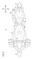
- FIG. 2 is a plan view of the motorcycle.
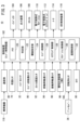
- FIG. 3 is a control block diagram of the motorcycle.
- FIG. 4 is a diagram showing the relationship between load and threshold.
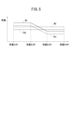
- FIG. 5 is a diagram showing the relationship between load and threshold.
- FIG. 6 is a diagram showing criteria for determining the running state.
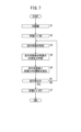
- FIG. 7 is a flow chart of the learning mode.
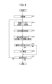
- FIG. 8 is a flowchart showing a change in threshold setting and a change in running mode.
- FIG. 1 is a left side view of a motorcycle 10 (straddle-type vehicle) according to one embodiment of the present invention.
- the direction in which the motorcycle 10 moves forward is defined as the forward direction, and the front/rear, left/right, and up/down directions will be described.
- the motorcycle 10 has a body frame 12.
- the body frame 12 includes a head pipe portion 14 , a pair of left and right main frames 16 , a pair of left and right center frames 18 , and a pair of left and right seat rails 20 .
- the head pipe portion 14 is the front end portion of the vehicle body frame 12 .
- a pair of main frames 16 extends rearward from the head pipe portion 14 in a left-right direction.
- the main frame 16 has a down frame portion 22 .
- the center frame 18 is connected to the rear end of the main frame 16 .
- the center frame 18 is bent and extends downward.
- the center frame 18 has a rear fork pivot portion 24 .
- the rear fork pivot portion 24 is a downward extending portion of the center frame 18 .
- the seat rails 20 are connected to bent portions of the center frame 18 .
- the seat rail 20 extends rearward and obliquely upward from the center frame 18 .
- the head pipe portion 14 supports a pair of left and right front forks 26 .
- the front fork 26 is operably supported by the head pipe portion 14 .
- a front wheel 28 is pivotally supported at the lower end of the front fork 26 .
- a steering handle 30 is connected to the upper end of the front fork 26 .
- a handle switch 32 and a clutch lever 34 are arranged on the left side of the steering handle 30 .
- a brake lever 36 and a throttle grip 38 are arranged on the right side of the steering handle 30 .
- a pivot shaft portion 40 is connected to the rear fork pivot portion 24 .
- a front end portion of a rear fork 42 is pivotally supported on the pivot shaft portion 40 .
- the rear fork 42 extends rearward from the pivot shaft portion 40 .
- a rear wheel 44 is pivotally supported at the rear end of the rear fork 42 .
- the rear wheel 44 can swing vertically.
- a power unit 46 is mounted on the body frame 12 .
- the power unit 46 is suspended between the down frame portion 22 and the center frame 18 .
- the power unit 46 is a drive source for the motorcycle 10 .
- the power unit 46 has an engine 48 and a transmission 50 .
- the engine 48 has a crankcase 52 .
- Transmission 50 is housed in the rear portion of crankcase 52 .
- the transmission 50 is a manual transmission type multi-speed transmission.
- the engine 48 is, for example, a water-cooled 4-cylinder 4-stroke cycle engine.
- Engine 48 further includes a crankshaft (not shown).
- the crankshaft portion is housed inside the crankcase 52 .
- the crankshaft portion extends in the left-right direction (vehicle width direction) inside the crankcase 52 .
- the crankshaft is rotatably supported inside the crankcase 52 .
- a cylinder block 54 is connected to the upper end of the crankcase 52 .
- a cylinder head 56 is connected to the upper end of the cylinder block 54 .
- the cylinder block 54 and the cylinder head 56 extend obliquely forward and upward so that the axis of the cylinder inclines forward.
- the upper end of the cylinder head 56 is covered with a cylinder head cover 58 .
- An intake pipe 62 is connected to the cylinder head 56 via a throttle body 60 .
- the intake pipe 62 extends upward from the throttle body 60 .
- the intake pipe 62 is connected to an air cleaner 64 .
- One end of an exhaust pipe 66 is connected to the cylinder head 56 .
- One end of the exhaust pipe 66 extends forward from the cylinder head 56 .
- the exhaust pipe 66 bends downward from one end and further bends rearward.
- the other end of the exhaust pipe 66 is connected to a rear muffler 68 .
- a fuel tank 70 is arranged above the power unit 46 .
- Fuel tank 70 is supported by main frame 16 and center frame 18 .
- a seat 72 is arranged behind the fuel tank 70 .
- the seat 72 is supported by the seat rails 20 .
- An occupant such as a driver sits on the seat 72 .
- the seat 72 is provided with a plurality of load sensors 74.
- a plurality of load sensors 74 are arranged inside the seat 72 .
- the plurality of load sensors 74 are arranged in different detection areas inside the seat 72 .
- the plurality of load sensors 74 are arranged inside the seat 72 in the vicinity of the upper surface of the seat 72 .
- eight load sensors 74 are arranged inside the seat 72 .
- the eight load sensors 74 are covered with a sensor cover 76 made of resin.
- Four of the eight load sensors 74 are arranged on the front side of the seat 72 .
- the four load sensors 74 on the front side are arranged at predetermined intervals along the left-right direction.
- the remaining four load sensors 74 of the eight load sensors 74 are arranged behind the seat 72 .
- the four load sensors 74 on the rear side are arranged at predetermined intervals along the left-right direction.
- the seat 72 has a shape in which the width in the left-right direction increases toward the rear. Therefore, the interval between the four load sensors 74 on the rear side is larger than the interval between the four load sensors 74 on the front side.
- Each load sensor 74 outputs a signal corresponding to the magnitude of the load when a load is applied from above such as when the passenger sits on the seat 72 .
- each load sensor 74 should be able to detect the load applied by the occupant.
- at least one load sensor 74 may be provided on the seat 72 .
- the load sensor 74 may be arranged at an arbitrary location on the seat 72 .
- the seat rails 20 are covered with a rear cowl 78.
- a camera 80 is arranged behind the rear cowl 78 . Camera 80 shoots forward. The camera 80 photographs, for example, an occupant seated on the seat 72 .
- a side stand 82 is attached to the lower end of the left rear fork pivot portion 24 .
- the side stand 82 is attached to the lower end of the left rear fork pivot portion 24 so as to be able to rise and fall.
- a front end portion of a support bracket 84 is fixed to the rear fork pivot portion 24 .
- a support bracket 84 extends rearwardly from the rear fork pivot portion 24 .
- a back step 86 is provided at the rear end of the support bracket 84 .
- the back step 86 protrudes outward in the vehicle width direction from the rear end portion of the support bracket 84 . The driver puts his foot on the back step 86 .
- FIG. 3 is a control block diagram of the motorcycle 10.
- the motorcycle 10 includes a communication unit 88, an engine speed sensor 90, a throttle opening sensor 92, a front wheel speed sensor 94, a rear wheel speed sensor 96, an inertial measurement unit (IMU) 98, a rotation angle sensor 100, and a control device 102. , injector 104 , ignition 106 , throttle 108 , electronically controlled suspension 110 , electronically controlled steering damper 112 , meter 114 and ABS controller 116 .
- Electronically controlled suspension 110 will be referred to as suspension 110 in the following description.
- the electronically controlled steering damper 112 is called a steering damper 112 .
- a crew member has a mobile device 118 (electronic key) such as a smartphone.
- the communication unit 88 can wirelessly transmit and receive signals or information with the mobile device 118 .
- Each of the multiple load sensors 74 detects the load applied by the occupant and outputs the detection result to the control device 102 .
- the handle switch 32 gives various instructions to the control device 102 based on the operation by the passenger.
- Engine speed sensor 90 detects the engine speed of engine 48 (see FIG. 1) and outputs the detection result to control device 102 .
- the throttle opening sensor 92 detects the opening of the throttle 108 or the amount of operation of the throttle grip 38 (see FIG. 2) by the driver, and outputs the detection result to the control device 102 .
- a front wheel speed sensor 94 detects the wheel speed of the front wheels 28 and outputs the detection result to the control device 102 .
- a rear wheel speed sensor 96 detects the wheel speed of the rear wheels 44 and outputs the detection result to the control device 102 .
- the inertial measurement device 98 detects the longitudinal, lateral, and vertical states of the motorcycle 10 and outputs the detection results to the control device 102 . Specifically, the inertial measurement device 98 detects three-dimensional acceleration and angular velocity of the motorcycle 10 and outputs the detection results to the control device 102 . These detection results also include the roll angle of the motorcycle 10 .
- the rotation angle sensor 100 detects whether or not the brake lever 36 is operated by the driver, and outputs the detection result to the control device 102 . Specifically, the brake lever 36 rotates around a rotation shaft (not shown) by the driver's operation. Rotation angle sensor 100 detects the rotation angle of brake lever 36 and outputs the detection result to control device 102 .
- the camera 80 captures an image of the occupant seated on the seat 72 (see FIG. 1) and outputs image data of the captured image of the occupant to the control device 102 .
- the control device 102 is an electronic control unit (ECU) such as an engine control device. By executing a program stored in the memory 120 (storage unit), the control device 102 controls a determination unit 122, a threshold value setting unit 124 (setting change unit), an engine control unit 126, a steering control unit 128, a suspension control unit 130. , and implements the functions of the cooperation control unit 132 .
- ECU electronice control unit
- the determination unit 122 determines that the occupant has performed an operation input to the load sensor 74 when the load sensor 74 detects a load exceeding the threshold.
- the operation input means that the occupant applies a load exceeding the threshold to the load sensor 74 in order to instruct the change of the running mode of the motorcycle 10 . Therefore, the load sensor 74 functions as an operation switch for the passenger to give an instruction to change the running mode.
- the travel mode is a mode for controlling travel of the motorcycle 10 when the motorcycle 10 travels on a predetermined road.
- the driving modes include a high-speed mode for driving on highways and the like and a low-speed mode for driving in urban areas and the like.
- the threshold is a value slightly larger than the load detected by the load sensor 74 when the occupant is seated on the seat 72 (see FIG. 1) (see FIG. 5).
- the load detected by the load sensor 74 is smaller than the threshold.
- the determination unit 122 determines that there is no operation input in the normal riding position.
- the determination unit 122 determines that there has been an operation input. Specifically, while the motorcycle 10 is running, the rider intentionally applies a large load to the load sensor 74 by, for example, pressing the seat 72 from above with the buttocks.
- the threshold differs for each load sensor 74, each traveling state of the motorcycle 10, and each rider. Each threshold is pre-stored in the memory 120 . Further, the running state of the motorcycle 10 includes a straight running state, an accelerating state, a braking state, and a turning state (see FIG. 6).
- the occupant has a portable device 118.
- portable device 118 functions as an electronic key, such as a smart key.
- the identification information (ID) of the portable device 118 becomes information indicating the occupant. That is, the threshold may differ for each piece of identification information of the portable device 118 possessed by the passenger.
- the threshold setting unit 124 sets a threshold for each load sensor 74, for each running state of the motorcycle 10, and for each passenger, and stores each set threshold in the memory 120. Also, the threshold setting unit 124 changes the threshold set in the determination unit 122 based on the running state of the motorcycle 10 . In this case, the threshold value setting unit 124 reads an appropriate threshold value according to the traveling state of the rider and the motorcycle 10 from among the threshold values stored in the memory 120 . The threshold setting unit 124 changes the threshold set in the determination unit 122 to the threshold read from the memory 120 . Accordingly, the determination unit 122 determines whether or not there is an operation input to the load sensor 74 by the passenger based on the changed threshold value.
- the threshold setting unit 124 may determine the physique and riding position of the passenger based on the image data from the camera 80. Thereby, the threshold setting unit 124 can identify the passenger based on the physique of the passenger. The threshold setting unit 124 can identify the running state of the motorcycle 10 from the riding position. The threshold setting unit 124 can change the threshold set in the determination unit 122 to an appropriate value based on the specified result.
- the engine control unit 126 controls the injector 104, the ignition device 106 and the throttle 108 based on each detection result input to the control device 102.
- Engine control unit 126 causes meter 114 to display various types of information.
- the engine control unit 126 adjusts the opening of the throttle 108 .
- Engine control unit 126 adjusts the amount of fuel supplied from fuel tank 70 to engine 48 by controlling injector 104 .
- Engine control unit 126 adjusts the ignition timing by controlling ignition device 106 .
- the engine control unit 126 causes the meter 114 to display various information such as the engine speed.
- the steering damper 112 is provided on the steering handle 30 (see FIG. 1).
- the steering damper 112 can change the operability of the steering handle 30 that steers the front wheels 28 .
- the steering control unit 128 changes the operability of the steering handle 30 by controlling the damping characteristics of the steering damper 112 .
- the suspension 110 is a front suspension provided on the front fork 26 (see FIG. 1) and a rear suspension (not shown) provided on the rear portion of the motorcycle 10 .
- Suspension control unit 130 changes the damping characteristics of suspension 110 or the vehicle height of motorcycle 10 .
- the construction of suspension 110 and steering damper 112 is well known. Therefore, detailed descriptions of the suspension 110 and the steering damper 112 are omitted.
- the cooperative control unit 132 controls the engine control unit 126, the steering control unit 128, and the suspension control unit 130 to adjust the output of the engine 48, the damping characteristics of the steering damper 112, the damping characteristics of the suspension 110, or the vehicle height. , cooperate to change. Further, when the determination unit 122 determines that there is an operation input by the driver, the cooperation control unit 132 changes the running mode of the motorcycle 10 to the high speed mode or the low speed mode. As a result, the cooperative control unit 132 performs the above-described coordinated change based on the changed driving mode.
- the memory 120 stores a combination of the output characteristics of the engine 48, the damping characteristics of the steering damper 112, and the damping characteristics of the suspension 110 or vehicle height according to the high speed mode and the low speed mode.
- the cooperative control unit 132 reads from the memory 120 a combination of the output characteristic of the engine 48, the damping characteristic of the steering damper 112, and the damping characteristic of the suspension 110 or the vehicle height according to the changed running mode. Therefore, the cooperation control unit 132 uses the combination read from the memory 120 to perform the above-described cooperative change. Note that the travel mode after the change is displayed on meter 114 .
- the cooperative control unit 132 may control the ABS control device 116 based on the changed driving mode.
- the ABS control device 116 can change the braking characteristics (traction control characteristics) of the ABS based on the control from the cooperative control section 132 .
- FIG. 4 and 5 are diagrams showing the relationship between the loads W1 and W2 applied by the occupant to the load sensor 74 (see FIG. 2) and the threshold values TH, TH1 and TH2.
- the riding position 134 (the seating position of the occupant on the seat 72) may differ for each occupant.
- the riding positions 134 of different occupants are indicated by two-dot chain lines. Since the riding position 134 is different, the magnitudes of the loads W1 and W2 detected by the load sensors 74 are also different, as shown in FIG. In FIG. 4, the difference between the loads W1 and W2 for each occupant for the four load sensors 74 is indicated by a solid line and a dashed line.
- the threshold TH is set to a constant value regardless of the occupant and the load sensor 74.
- the threshold TH is indicated by a dashed line.
- the determination unit 122 can determine that there is an operation input from one of the occupants.
- the determination unit 122 determines that there is no operation input from the other occupant. .
- the thresholds TH1 and TH2 set in the determination unit 122 are changed for each passenger and for each load sensor 74.
- the solid line indicates the load W1 applied to each load sensor 74 (see FIG. 2) by one of the occupants
- the broken line indicates the threshold TH1 corresponding to one of the occupants.
- the load W2 applied to each load sensor 74 by the other occupant is indicated by a one-dot chain line
- the threshold value TH2 corresponding to the other occupant is indicated by a two-dot chain line. Since the thresholds TH1 and TH2 are different for each passenger, it is possible to suppress erroneous determination by the determination unit 122 . Also, the sensitivity of operation input can be improved.
- the riding position 134 may differ depending on the running state of the motorcycle 10 (see FIG. 1). As the riding position 134 changes, the magnitudes of the loads W1 and W2 detected by the load sensors 74 also change.
- FIG. 6 is a diagram showing criteria for judging the running state of the motorcycle 10 (see FIG. 1).
- the running state of the motorcycle 10 includes a straight running state, an accelerating state, a braking state, and a turning state.
- the threshold value setting unit 124 determines the running state based on the vehicle speed (velocity), acceleration, amount of change in throttle opening, presence/absence of brake operation, and roll angle.
- the threshold setting unit 124 (see FIG. 3) is based on the wheel speed of the front wheels 28 detected by the front wheel speed sensor 94 or the wheel speed of the rear wheels 44 detected by the rear wheel speed sensor 96, A vehicle speed (velocity) of the motorcycle 10 is calculated.
- the threshold value setting unit 124 uses the calculated vehicle speed for determining the running state.
- the threshold setting unit 124 can calculate the acceleration of the motorcycle 10 based on the wheel speed of the front wheels 28 or the wheel speed of the rear wheels 44 .
- the threshold value setting unit 124 uses the calculated acceleration or the acceleration detected by the inertial measurement device 98 for determining the running state.
- the threshold value setting unit 124 uses the amount of change in the throttle opening detected by the throttle opening sensor 92 for determining the running state.
- the threshold value setting unit 124 uses the rotation angle of the brake lever 36 detected by the rotation angle sensor 100 for determining the running state. Specifically, the threshold setting unit 124 determines that the brake lever 36 has been operated when the rotation angle exceeds a predetermined angle.
- the threshold setting unit 124 uses the roll angle detected by the inertial measurement device 98 for determining the running state.
- the threshold setting unit 124 determines that the vehicle speed is a constant speed of 40 [km/h] or higher, the acceleration is approximately 0, the amount of change in the throttle opening is small, the brake lever 36 is not operated, and the absolute value of the roll angle is less than 2[°] (upright state), it is determined that the motorcycle 10 is traveling straight.
- the occupant is seated on the center portion of the upper surface of the seat 72 in the straight-ahead state. At this time, the occupant applies a load to the central portion of the upper surface of the seat 72 from above. As a result, all the load sensors 74 receive the load from the occupant.
- the threshold value setting unit 124 determines that the vehicle speed increases with time, the motorcycle 10 accelerates (positive acceleration), the amount of change in the throttle opening is large, the brake lever 36 is not operated, and the absolute value of the roll angle is less than 2 [°], it is determined that the motorcycle 10 is in an accelerating state.
- the occupant In an accelerated state, the occupant is seated on the seat 72 in a state of being biased toward the front side of the seat 72 . The occupant applies a load to the front portion of the upper surface of the seat 72 . Therefore, the load sensor 74 on the front side receives the load from the passenger.
- the threshold value setting unit 124 determines that the vehicle speed decreases over time, the motorcycle 10 decelerates (negative acceleration), the throttle opening is approximately 0 (fully closed), the brake lever 36 is operated, When the absolute value of the roll angle is less than 2[°], it is determined that the motorcycle 10 is in a braking state (deceleration state). In the braking state, the occupant sits on the seat 72 in a state of being biased toward the rear side of the seat 72 . The occupant applies a load to the rear portion of the upper surface of the seat 72 . Therefore, the load sensor 74 on the rear side receives the load from the passenger.
- the threshold setting unit 124 determines that the motorcycle 10 is turning when the vehicle speed is 40 [km/h] or more and the roll angle is an arbitrary angle (the motorcycle 10 is tilted).
- the occupant In the turning state, the occupant is seated on the right side or the left side of the seat 72 in a biased state. The occupant applies a load to the right side or left side of the upper surface of the seat 72 . Therefore, the load sensor 74 on the right side or the load sensor 74 on the left side receives the load from the occupant.
- FIG. 7 the operation of the motorcycle 10 will be described with reference to FIGS. 7 and 8.
- FIG. 7 is a flowchart for setting thresholds for each passenger, each load sensor 74 (see FIG. 2), and each running state, and storing each set threshold in the memory 120 (see FIG. 3). The operation of FIG. 7 is performed for each passenger.
- step S1 the communication unit 88 (see FIG. 3) receives identification information from the portable device 118 of the passenger.
- the communication unit 88 outputs the received identification information to the control device 102 .
- Control device 102 stores the input identification information in memory 120 .
- Control device 102 displays on meter 114 that the identification information has been recognized. By checking the content displayed on the meter 114, the passenger can know that the control device 102 has recognized the identification information.
- step S2 the occupant operates the handle switch 32 to instruct the start of the learning mode for performing threshold setting processing.
- the handle switch 32 outputs a signal to the control device 102 in accordance with the operation content of the passenger. Based on the input of the signal, the control device 102 puts each unit in the control device 102 into an operable state. This turns on the learning mode. Controller 102 also displays on meter 114 that the learning mode has been turned on. By checking the display contents of the meter 114, the passenger can understand that the learning mode has been turned on.
- step S3 the passenger sits on the seat 72 and drives the motorcycle 10. While the motorcycle 10 is running, the detection results of the engine speed sensor 90 and the like are sequentially input to the control device 102 .
- the threshold value setting unit 124 determines the current running state of the motorcycle 10 based on each detection result input to the control device 102 and the determination criteria shown in FIG.
- each load sensor 74 detects the load applied by the occupant and outputs the detection result to the control device 102 .
- the threshold setting unit 124 acquires (learns) each input detection result.
- step S5 the threshold setting unit 124 sets a threshold according to the driving state based on each acquired detection result (load) and the determined driving state.
- the threshold value setting unit 124 sets a threshold value slightly larger than the detected load for each of the load sensors 74 .
- the threshold setting unit 124 stores the set threshold in the memory 120 . In this case, the threshold setting unit 124 stores the threshold in the memory 120 in association with the passenger (identification information).
- step S6 the threshold setting unit 124 determines whether the motorcycle 10 has stopped traveling based on the vehicle speed and the like.
- step S6 NO
- the threshold setting unit 124 repeatedly executes the processes of steps S3 to S5. As a result, a threshold value is set for each traveling state and each load sensor 74 for the passenger seated on the seat 72 and stored in the memory 120 .
- the threshold differs for each running state. For example, in an accelerated state, the load detected by the front load sensor 74 is greater than the load detected by the rear load sensor 74 . Therefore, in an accelerating state, the threshold for the load sensor 74 on the front side is set large, and the threshold for the load sensor 74 on the rear side is set small.
- step S6 When the motorcycle 10 has stopped traveling (step S6: YES), the threshold setting unit 124 proceeds to step S7.
- step S7 the threshold setting unit 124 turns off the learning mode.
- Threshold setting unit 124 displays on meter 114 that the learning mode has been turned off. By checking the content displayed on the meter 114, the passenger can know that the learning mode has been turned off.
- the motorcycle 10 When setting the threshold for each passenger, the motorcycle 10 may be run for each passenger and the learning mode described above may be executed. In the above process, after the control device 102 recognizes the identification information in step S1, the control device 102 may automatically turn on the learning mode in step S2.
- FIG. 8 is a flow chart showing the process of changing the threshold according to the running state and the process of changing the running mode.
- step S11 the communication unit 88 (see FIG. 3) receives identification information from the portable device 118 of the passenger.
- the communication unit 88 outputs the received identification information to the control device 102 .
- the threshold setting unit 124 reads from the memory 120 the threshold corresponding to the identification information input to the control device 102 .
- the threshold setting unit 124 sets the read threshold as a threshold used for determination processing in the determination unit 122 .
- step S12 the cooperative control unit 132 sets the running mode of the motorcycle 10 (see FIG. 1). Specifically, the cooperation control unit 132 sets the high speed mode or the low speed mode. In this case, the cooperative control unit 132 sets the running mode of the previous run as the current running mode.
- step S13 the rider sits on the seat 72 and drives the motorcycle 10. While the motorcycle 10 is running, the detection results of the engine speed sensor 90 and the like are sequentially input to the control device 102 . Similar to step S3 (see FIG. 7), the threshold value setting unit 124 determines the current running state of the motorcycle 10 based on each detection result input to the control device 102 and the criteria shown in FIG. .
- step S14 the threshold value setting unit 124 reads from the memory 120 a threshold value corresponding to the passenger seated on the seat 72 and the determined running state.
- the threshold setting unit 124 changes the threshold set in the determination unit 122 to the threshold read from the memory 120 . Note that in steps S13 and S14, if there is no change in the running state, the threshold value setting unit 124 does not change the threshold value.
- step S15 the determination unit 122 determines whether the detected load exceeds the threshold for each of the plurality of load sensors 74. In this case, if the loads detected by all the load sensors 74 exceed the threshold values, it is determined that the occupant has performed an operation input to each load sensor 74 (step S15: YES).
- the determination unit 122 may determine that the occupant has performed an operation input when all the load sensors 74 continuously detect a load exceeding the threshold two or more times within a predetermined time. (Step S15: YES). As a result, erroneous determination by the determination unit 122 can be reliably prevented.
- step S15 if the load detected by a certain number or more of the load sensors 74 out of all the load sensors 74 exceeds the threshold value, the determination unit 122 can also determine that the operation input has been performed. (Step S15: YES).
- step S15 when it is determined that the passenger has performed an operation input (step S15: YES), the determination unit 122 notifies the cooperation control unit 132 that the passenger has performed an operation input.
- step S16 the cooperative control unit 132 changes the running mode.
- the cooperative control unit 132 controls the engine control unit 126, the steering control unit 128, and the suspension control unit 130 in the changed running mode. Accordingly, the engine control unit 126, the steering control unit 128, and the suspension control unit 130 control the running of the motorcycle 10 in the changed running mode.
- step S15 When it is determined in step S15 that there is no operation input by the passenger (step S15: NO), the determination unit 122 notifies the cooperation control unit 132 that there is no operation input by the passenger.
- the cooperative control unit 132 controls the engine control unit 126, the steering control unit 128, and the suspension control unit 130 in the current running mode. Accordingly, the engine control unit 126, the steering control unit 128, and the suspension control unit 130 control the running of the motorcycle 10 in the current running mode.
- step S17 the cooperative control unit 132 determines whether the motorcycle 10 has stopped traveling based on the vehicle speed or the like.
- step S17 NO
- the processing of steps S12 to S16 is repeatedly executed in the control device 102.
- step S17 When the motorcycle 10 has stopped traveling (step S17: YES), the process of FIG. 8 ends.
- the driving mode is changed based on the operation input to each load sensor 74 by the driver.
- the present invention is a straddle-type vehicle (10) comprising a seat (72) on which an occupant sits, wherein the straddle-type vehicle (10) includes a load sensor (74) provided on the seat (72). and a control device (102) for controlling travel of the straddle-type vehicle (10) in a predetermined travel mode, wherein the control device (102) detects a load when the load sensor (74) exceeds a threshold value.
- the determination unit (122) determines that the occupant has performed an operation input to the load sensor (74), and the determination unit (122) determines that the occupant has performed the operation input
- a controller (126, 128, 130, 132) for controlling the running of the straddle-type vehicle (10) in the running mode corresponding to the operation input, and the running state of the straddle-type vehicle (10).
- a setting changing unit (124) for changing the setting of the threshold based on the above.
- an occupant such as a driver performs operation input by applying a load to the load sensor.
- the occupant can give an instruction to change the running mode while gripping the steering wheel while the straddle-type vehicle is running. That is, the passenger can easily change the running mode regardless of the running state of the straddle-type vehicle. Since the setting of the threshold value is changed according to the running state of the straddle-type vehicle, erroneous determination of the operation input can be suppressed and the sensitivity of the operation input can be improved.
- the straddle-type vehicle (10) comprises a plurality of load sensors (74), the plurality of load sensors (74) being arranged in different detection areas on the seat (72), The threshold may be different for each load sensor (74).
- the determination unit (122) may determine that the occupant has performed the operation input when the load sensor (74) continuously detects the load exceeding the threshold value a plurality of times. .
- the setting change section (124) may determine the running state based on the acceleration of the straddle-type vehicle (10).
- the driving state can be classified according to the presence or absence of acceleration.
- different threshold values can be set for each running state. Also, when the riding position of the passenger changes according to the acceleration, it is possible to easily cope with the change of the riding position.
- the setting change unit (124) may determine the running state based on the acceleration, the throttle opening of the straddle-type vehicle (10), and the presence or absence of brake operation by the passenger. good.
- the setting change section (124) may determine the running state based on the roll angle of the straddle-type vehicle (10).
- the vehicle can be classified into a turning state or another running state. Even in this case, a different threshold can be set for each running state.
- the riding position of the occupant changes depending on whether the vehicle is turning or going straight, the change in riding position can be easily handled.
- the setting change section (124) may determine the running state based on the vehicle speed of the straddle-type vehicle (10) and the roll angle.
- the straddle-type vehicle (10) further includes a storage section (120) for storing the threshold value for each running state, and the setting change section (124) changes the threshold value according to the running state. from the storage unit (120), the setting of the threshold may be changed.
- the storage unit (120) stores the threshold value for each passenger, and the setting change unit (124) sets the threshold value according to the passenger and the driving state to the storage unit (120).
- the setting of the threshold may be changed by reading from.
- the storage unit (120) stores the threshold for each identification information of the electronic key (118) possessed by the passenger
- the setting change unit (124) stores the threshold from the electronic key (118).
- the setting of the threshold may be changed by reading the threshold corresponding to the identification information and the running state from the storage unit (120).
- the threshold set in the determination unit can be automatically changed. As a result, it becomes unnecessary for the passenger to manually change the setting of the threshold. It can be a user-friendly configuration.
- the threshold value may be a value larger than the load detected by the load sensor (74) while the occupant is seated on the seat (72).
Landscapes
- Engineering & Computer Science (AREA)
- Automation & Control Theory (AREA)
- Transportation (AREA)
- Mechanical Engineering (AREA)
- Human Computer Interaction (AREA)
- Control Of Vehicle Engines Or Engines For Specific Uses (AREA)
- Control Of Driving Devices And Active Controlling Of Vehicle (AREA)
Abstract
鞍乗型車両である自動二輪車(10)において、制御装置(102)の判定部(122)は、荷重センサ(74)が閾値を超える荷重を検出したときに、乗員が荷重センサ(74)に対して操作入力を行ったと判定する。制御装置(102)は、乗員が操作入力を行ったと判定部(122)が判定したときに、操作入力に応じた走行モードで自動二輪車(10)の走行を制御する。閾値設定部(124)は、自動二輪車(10)の走行状態に基づき、閾値の設定を変更する。
Description
本発明は、鞍乗型車両に関する。
特許第6623246号公報には、ハンドルスイッチ及び制御装置を備える鞍乗型車両が開示されている。ハンドルスイッチは、ハンドルの左側に配置されている。制御装置は、所定の走行モードで鞍乗型車両の走行を制御する。運転者は、ハンドルスイッチを操作することにより、走行モードの変更を指示する。これにより、制御装置は、運転者からの指示に基づき走行モードを変更し、変更後の走行モードで鞍乗型車両の走行を制御する。
鞍乗型車両の走行中、運転者は、ハンドルを把持している。運転者がハンドルを握った状態で、ハンドルスイッチを操作することは難しい。
本発明は、上述した課題を解決することを目的とする。
本発明の態様は、乗員が着座するシートを備えた鞍乗型車両であって、前記鞍乗型車両は、前記シートに設けられた荷重センサと、所定の走行モードで前記鞍乗型車両の走行を制御する制御装置と、をさらに備え、前記制御装置は、前記荷重センサが閾値を超える荷重を検出したときに、前記乗員が前記荷重センサに対して操作入力を行ったと判定する判定部と、前記乗員が前記操作入力を行ったと前記判定部が判定したときに、前記操作入力に応じた前記走行モードで前記鞍乗型車両の走行を制御する制御部と、前記鞍乗型車両の走行状態に基づき、前記閾値の設定を変更する設定変更部と、を有する。
本発明によれば、運転者等の乗員は、荷重センサに荷重を加えることで、操作入力を行う。これにより、乗員は、鞍乗型車両の走行中、ハンドルを握った状態で、走行モードの変更を指示することができる。すなわち、乗員は、鞍乗型車両の走行状態に関わらず、走行モードを容易に変更することができる。鞍乗型車両の走行状態に応じて閾値の設定が変更されるので、操作入力の誤判定が抑制されると共に、操作入力の感度を向上させることができる。
図1は、本発明の一実施形態に係る自動二輪車10(鞍乗型車両)の左側面図である。以下の説明では、自動二輪車10が前進する方向を前方として、前後、左右及び上下の方向を説明する。
自動二輪車10は、車体フレーム12を有する。車体フレーム12は、ヘッドパイプ部14と、左右一対のメインフレーム16と、左右一対のセンターフレーム18と、左右一対のシートレール20とを備える。
ヘッドパイプ部14は、車体フレーム12の前端部である。一対のメインフレーム16は、ヘッドパイプ部14から左右に分かれて後方に延出している。メインフレーム16は、ダウンフレーム部22を備える。センターフレーム18は、メインフレーム16の後端に連結されている。センターフレーム18は、屈曲して下方に延びている。センターフレーム18は、リアフォークピボット部24を有する。リアフォークピボット部24は、センターフレーム18のうちの下方への延出部分である。シートレール20は、センターフレーム18の屈曲部分に連結されている。シートレール20は、センターフレーム18から後方斜め上方に延びている。
ヘッドパイプ部14は、左右一対のフロントフォーク26を支持する。フロントフォーク26は、操行可能にヘッドパイプ部14に支持されている。フロントフォーク26の下端には、前輪28が軸支されている。フロントフォーク26の上端には、ステアリングハンドル30が連結されている。ステアリングハンドル30の左側には、ハンドルスイッチ32と、クラッチレバー34とが配されている。図2に示すように、ステアリングハンドル30の右側には、ブレーキレバー36と、スロットルグリップ38とが配されている。
図1に示すように、リアフォークピボット部24には、ピボット軸部40が連結されている。ピボット軸部40には、リアフォーク42の前端部が軸支されている。リアフォーク42は、ピボット軸部40から後方に延びている。リアフォーク42の後端部には、後輪44が軸支されている。後輪44は、上下方向に揺動可能である。
車体フレーム12には、パワーユニット46が搭載されている。パワーユニット46は、ダウンフレーム部22とセンターフレーム18とに懸架されている。パワーユニット46は、自動二輪車10の駆動源である。パワーユニット46は、エンジン48と、変速機50とを備える。エンジン48は、クランクケース52を備える。変速機50は、クランクケース52内の後部に収容されている。変速機50は、マニュアル変速式の多段変速機である。
エンジン48は、例えば、水冷4気筒の4ストロークサイクルエンジンである。エンジン48は、クランク軸部(不図示)をさらに備える。クランク軸部は、クランクケース52の内部に収容されている。クランク軸部は、クランクケース52の内部で、左右方向(車幅方向)に延びている。クランク軸部は、クランクケース52の内部で、回転可能に軸支されている。クランクケース52の上端部には、シリンダブロック54が連結されている。シリンダブロック54の上端部には、シリンダヘッド56が連結されている。シリンダブロック54及びシリンダヘッド56は、シリンダの軸線が前方に傾斜するように、前方斜め上方に延びている。シリンダヘッド56の上端には、シリンダヘッドカバー58が被せられている。
シリンダヘッド56には、スロットルボディ60を介して、吸気管62が連結されている。吸気管62は、スロットルボディ60から上方に延びている。吸気管62は、エアクリーナ64に接続されている。シリンダヘッド56には、排気管66の一端部が連結されている。排気管66の一端部は、シリンダヘッド56から前方に延びている。排気管66は、一端部から下方へ曲がり、後方にさらに曲がっている。排気管66の他端部は、後方のマフラー68に接続されている。
パワーユニット46の上方には、燃料タンク70が配されている。燃料タンク70は、メインフレーム16及びセンターフレーム18に支持されている。燃料タンク70の後方には、シート72が配されている。シート72は、シートレール20に支持されている。シート72には、運転者等の乗員が着座する。
図2に示すように、シート72には、複数の荷重センサ74が設けられている。複数の荷重センサ74は、シート72の内部に配されている。複数の荷重センサ74は、シート72の内部において、互いに異なる検出領域に配置されている。
具体的には、複数の荷重センサ74は、シート72の内部におけるシート72の上面近傍の箇所に配置されている。図2では、8つの荷重センサ74がシート72の内部に配置されている。8つの荷重センサ74は、樹脂製のセンサカバー76で覆われている。8つの荷重センサ74のうち、4つの荷重センサ74は、シート72の前側に配置されている。前側の4つの荷重センサ74は、左右方向に沿って、所定間隔で配置されている。8つの荷重センサ74のうち、残りの4つの荷重センサ74は、シート72の後側に配置されている。後側の4つの荷重センサ74は、左右方向に沿って、所定間隔で配置されている。
シート72は、後方に向かう程、左右方向の幅が大きくなる形状を有する。そのため、後側の4つの荷重センサ74の間隔は、前側の4つの荷重センサ74の間隔よりも大きい。各荷重センサ74は、乗員のシート72への着座等によって、上方から荷重が加えられたときに、荷重の大きさに応じた信号を出力する。
なお、各荷重センサ74は、乗員から加えられる荷重を検出できればよい。本実施形態では、少なくとも1つの荷重センサ74がシート72に設けられていればよい。また、荷重センサ74は、シート72の任意の箇所に配置されていればよい。
図1に示すように、シートレール20は、リアカウル78で覆われている。リアカウル78の後部には、カメラ80が配置されている。カメラ80は、前方を撮影する。カメラ80は、例えば、シート72に着座した乗員を撮影する。
左側のリアフォークピボット部24の下端には、サイドスタンド82が取り付けられている。サイドスタンド82は、左側のリアフォークピボット部24の下端に起伏可能に取り付けられている。
リアフォークピボット部24には、支持ブラケット84の前端部が固定されている。支持ブラケット84は、リアフォークピボット部24から後方に延びている。支持ブラケット84の後端部には、バックステップ86が設けられている。バックステップ86は、支持ブラケット84の後端部から車幅方向外側に突出している。運転者は、バックステップ86に足を載せる。
図3は、自動二輪車10の制御ブロック図である。自動二輪車10は、通信部88、エンジン回転数センサ90、スロットル開度センサ92、前輪車輪速センサ94、後輪車輪速センサ96、慣性計測装置(IMU)98、回転角センサ100、制御装置102、インジェクタ104、点火装置106、スロットル108、電子制御式サスペンション110、電子制御式ステアリングダンパ112、メータ114、及び、ABS制御装置116をさらに備える。以下の説明では、電子制御式サスペンション110をサスペンション110と呼称する。電子制御式ステアリングダンパ112をステアリングダンパ112と呼称する。
乗員は、スマートフォン等の携帯機器118(電子キー)を所持している。通信部88は、携帯機器118との間で、無線による信号又は情報の送受信が可能である。
複数の荷重センサ74の各々は、乗員から加えられた荷重を検出し、その検出結果を制御装置102に出力する。ハンドルスイッチ32は、乗員による操作に基づき、制御装置102に各種の指示を与える。エンジン回転数センサ90は、エンジン48(図1参照)のエンジン回転数を検出し、その検出結果を制御装置102に出力する。スロットル開度センサ92は、スロットル108の開度、又は、運転者によるスロットルグリップ38(図2参照)の操作量を検出し、その検出結果を制御装置102に出力する。前輪車輪速センサ94は、前輪28の車輪速を検出し、その検出結果を制御装置102に出力する。後輪車輪速センサ96は、後輪44の車輪速を検出し、その検出結果を制御装置102に出力する。
慣性計測装置98は、自動二輪車10の前後方向、左右方向及び上下方向の状態を検出し、その検出結果を制御装置102に出力する。具体的には、慣性計測装置98は、自動二輪車10の三次元の加速度及び角速度を検出し、その検出結果を制御装置102に出力する。これらの検出結果には、自動二輪車10のロール角度も含まれる。
回転角センサ100は、運転者によるブレーキレバー36の操作の有無を検出し、その検出結果を制御装置102に出力する。具体的には、ブレーキレバー36は、運転者の操作によって、回動軸(不図示)を中心に回動する。回転角センサ100は、ブレーキレバー36の回動角度を検出し、その検出結果を制御装置102に出力する。
カメラ80は、シート72(図1参照)に着座する乗員を撮影し、撮影した乗員の画像データを制御装置102に出力する。
制御装置102は、エンジン制御装置等の電子制御装置(ECU)である。制御装置102は、メモリ120(記憶部)に格納されたプログラムを実行することで、判定部122、閾値設定部124(設定変更部)、エンジン制御部126、ステアリング制御部128、サスペンション制御部130、及び、連携制御部132の機能を実現する。
判定部122は、荷重センサ74が閾値を超える荷重を検出したときに、乗員が荷重センサ74に対して操作入力を行ったと判定する。操作入力とは、自動二輪車10の走行モードの変更を指示するため、閾値を超える荷重を乗員が荷重センサ74に加えることをいう。従って、荷重センサ74は、乗員が走行モードの変更を指示するための操作スイッチとして機能する。なお、走行モードは、自動二輪車10が所定の道路を走行するときに、該自動二輪車10の走行を制御するためのモードである。具体的には、走行モードには、高速道路等で走行するための高速モードと、市街地等で走行するための低速モードとがある。
閾値は、乗員がシート72(図1参照)に着座している状態で、荷重センサ74が検出する荷重よりも僅かに大きな値である(図5参照)。乗員が普通にシート72に着座している状態(通常のライディングポジション)では、荷重センサ74が検出する荷重は、閾値よりも小さい。判定部122は、通常のライディングポジションでは、操作入力が無いと判定する。
乗員が閾値よりも大きな荷重を荷重センサ74に意図的に加えた場合、判定部122は、操作入力があったと判定する。具体的には、自動二輪車10の走行中、乗員は、例えば、臀部で上方からシート72を押すことにより、大きな荷重を荷重センサ74に意図的に加える。
閾値は、荷重センサ74毎、自動二輪車10の走行状態毎、及び、乗員毎に異なる。各閾値は、メモリ120に予め記憶されている。また、自動二輪車10の走行状態には、直進状態と、加速状態と、制動状態と、旋回状態とがある(図6参照)。
乗員は、携帯機器118を所持している。本実施形態では、携帯機器118をスマートキーのような電子キーとして機能させる。これにより、携帯機器118の識別情報(ID)が乗員を示す情報となる。つまり、閾値は、乗員が所持する携帯機器118の識別情報毎に異なってもよい。
閾値設定部124は、荷重センサ74毎、自動二輪車10の走行状態毎、及び、乗員毎に閾値を設定し、設定した各閾値をメモリ120に記憶する。また、閾値設定部124は、自動二輪車10の走行状態に基づき、判定部122に設定されている閾値を変更する。この場合、閾値設定部124は、メモリ120に記憶されている各閾値のうち、乗員及び自動二輪車10の走行状態に応じた適切な閾値を読み出す。閾値設定部124は、判定部122に設定されている閾値を、メモリ120から読み出した閾値に変更する。これにより、判定部122は、変更後の閾値に基づき、乗員による荷重センサ74への操作入力の有無を判定する。
あるいは、閾値設定部124は、カメラ80からの画像データに基づき、乗員の体格及びライディングポジションを判断してもよい。これにより、閾値設定部124は、乗員の体格から該乗員を特定することができる。閾値設定部124は、ライディングポジションから自動二輪車10の走行状態を特定することができる。閾値設定部124は、特定した結果に基づき、判定部122に設定されている閾値を適切な値に変更することができる。
具体的な閾値の設定の変更処理については、後述する。
エンジン制御部126は、制御装置102に入力された各検出結果に基づき、インジェクタ104、点火装置106及びスロットル108を制御する。エンジン制御部126は、メータ114に各種の情報を表示させる。
具体的には、エンジン制御部126は、スロットル108の開度を調整する。エンジン制御部126は、インジェクタ104を制御することで、燃料タンク70からエンジン48に供給される燃料量を調整する。エンジン制御部126は、点火装置106を制御することで、点火時期を調整する。エンジン制御部126は、エンジン回転数等の各種の情報をメータ114に表示させる。
ステアリングダンパ112は、ステアリングハンドル30(図1参照)に備わる。ステアリングダンパ112は、前輪28を操舵するステアリングハンドル30の操作性を変更可能である。ステアリング制御部128は、ステアリングダンパ112の減衰特性を制御することで、ステアリングハンドル30の操作性を変更させる。
サスペンション110は、フロントフォーク26(図1参照)に備わるフロントサスペンションと、自動二輪車10の後部に設けられるリアサスペンション(不図示)とである。サスペンション制御部130は、サスペンション110の減衰特性、又は、自動二輪車10の車高を変更させる。サスペンション110及びステアリングダンパ112の構成は周知である。そのため、サスペンション110及びステアリングダンパ112の詳細な説明は、省略する。
連携制御部132は、エンジン制御部126、ステアリング制御部128及びサスペンション制御部130を制御することにより、エンジン48の出力と、ステアリングダンパ112の減衰特性と、サスペンション110の減衰特性又は車高とを、連携して変更させる。また、運転者による操作入力があったと判定部122が判定したときに、連携制御部132は、自動二輪車10の走行モードを、高速モード又は低速モードに変更する。これにより、連携制御部132は、変更後の走行モードに基づき、上記の連携した変更を行う。
なお、メモリ120には、高速モード及び低速モードに応じたエンジン48の出力特性、ステアリングダンパ112の減衰特性、及び、サスペンション110の減衰特性又は車高の組み合わせが記憶されている。連携制御部132は、変更後の走行モードに応じたエンジン48の出力特性、ステアリングダンパ112の減衰特性、及び、サスペンション110の減衰特性又は車高の組み合わせを、メモリ120から読み出す。従って、連携制御部132は、メモリ120から読み出した組み合わせを用いて、上記の連携した変更を行う。なお、変更後の走行モードは、メータ114に表示される。
連携制御部132は、変更後の走行モードに基づき、ABS制御装置116を制御してもよい。ABS制御装置116は、連携制御部132からの制御に基づき、ABSの制動特性(トラクションコントロール特性)を変更することができる。
図4及び図5は、乗員から荷重センサ74(図2参照)に加えられる荷重W1、W2と、閾値TH、TH1、TH2との関係を示す図である。
図2に示すように、乗員毎にライディングポジション134(シート72における乗員の着座位置)が異なる場合がある。図2では、異なる乗員のライディングポジション134を、二点鎖線で示している。ライディングポジション134が異なるため、図4に示すように、各荷重センサ74が検出する荷重W1、W2の大きさも異なる。図4では、4つの荷重センサ74について、乗員毎の荷重W1、W2の違いを実線と一点鎖線とで示している。
図4では、乗員の違い、及び、荷重センサ74の違いに関わりなく、閾値THが一定値に設定されている。図4では、閾値THを破線で示す。この場合、一方の乗員が臀部をシート72(図2参照)に押し付けると、実線で示すように、2つの荷重センサ74で検出される荷重W1が閾値THを超える。これにより、判定部122(図3参照)は、一方の乗員から操作入力があったと判定することができる。しかしながら、他方の乗員が臀部をシート72に押し付けても、各荷重センサ74で検出される荷重W2が閾値TH以下である場合、判定部122は、他方の乗員からの操作入力が無いと判定する。
そこで、本実施形態では、図5に示すように、乗員毎に、及び、荷重センサ74毎に、判定部122(図3参照)に設定されている閾値TH1、TH2を変更する。図5では、一方の乗員が各荷重センサ74(図2参照)に加える荷重W1を実線で示し、一方の乗員に応じた閾値TH1を破線で示している。また、図5では、他方の乗員が各荷重センサ74に加える荷重W2を一点鎖線で示し、他方の乗員に応じた閾値TH2を二点鎖線で示している。乗員毎に閾値TH1、TH2が異なるため、判定部122が誤判定することを抑制することができる。また、操作入力の感度を向上させることができる。
また、同じ乗員であっても、自動二輪車10(図1参照)の走行状態によって、ライディングポジション134が異なる場合がある。ライディングポジション134が異なることで、各荷重センサ74が検出する荷重W1、W2の大きさも変化する。
そこで、本実施形態では、同じ乗員について、走行状態毎に、判定部122に設定されている閾値を変更することが可能である。この場合も、判定部122が誤判定することを抑制させることができると共に、操作入力の感度を向上させることができる。
図6は、自動二輪車10(図1参照)の走行状態の判定基準を示す図である。自動二輪車10の走行状態には、直進状態と、加速状態と、制動状態と、旋回状態とがある。閾値設定部124は、車速(速度)、加速度、スロットル開度の変化量、ブレーキ操作の有無、及び、ロール角度に基づき、走行状態を判断する。
具体的には、閾値設定部124(図3参照)は、前輪車輪速センサ94が検出した前輪28の車輪速、又は、後輪車輪速センサ96が検出した後輪44の車輪速に基づき、自動二輪車10の車速(速度)を算出する。閾値設定部124は、算出した車速を走行状態の判断処理に用いる。
閾値設定部124は、前輪28の車輪速又は後輪44の車輪速に基づき、自動二輪車10の加速度を算出可能である。閾値設定部124は、算出した加速度、又は、慣性計測装置98が検出した加速度を、走行状態の判断処理に用いる。
閾値設定部124は、スロットル開度センサ92が検出したスロットル開度の変化量を、走行状態の判断処理に用いる。
閾値設定部124は、回転角センサ100が検出したブレーキレバー36の回転角を、走行状態の判断処理に用いる。具体的には、閾値設定部124は、回転角が所定角度を超えたときに、ブレーキレバー36の操作があったと判断する。
閾値設定部124は、慣性計測装置98が検出したロール角度を、走行状態の判断処理に用いる。
閾値設定部124は、車速が40[km/h]以上の一定速度であり、加速度が略0であり、スロットル開度の変化量が小さく、ブレーキレバー36の操作が無く、ロール角度の絶対値が2[°]未満(直立状態)であるときに、自動二輪車10が直進状態であると判断する。直進状態では、乗員は、シート72の上面の中央部に着座している。このときに、乗員は、上方からシート72の上面のうちの中央部に荷重を加えている。これにより、全ての荷重センサ74が乗員から荷重を受ける。
閾値設定部124は、車速が時間経過に伴って増加し、自動二輪車10が加速し(正の加速度)、スロットル開度の変化量が大きく、ブレーキレバー36の操作が無く、ロール角度の絶対値が2[°]未満であるときに、自動二輪車10が加速状態であると判断する。加速状態では、乗員は、シート72の前側に偏重した状態で該シート72に着座している。乗員は、シート72の上面における前側部分に荷重を加えている。そのため、前側の荷重センサ74が乗員から荷重を受ける。
閾値設定部124は、車速が時間経過に伴って低下し、自動二輪車10が減速し(負の加速度)、スロットル開度が略0(全閉状態)であり、ブレーキレバー36の操作が有り、ロール角度の絶対値が2[°]未満であるときに、自動二輪車10が制動状態(減速状態)であると判断する。制動状態では、乗員は、シート72の後側に偏重した状態で該シート72に着座している。乗員は、シート72の上面における後側部分に荷重を加えている。そのため、後側の荷重センサ74が乗員から荷重を受ける。
閾値設定部124は、車速が40[km/h]以上であり、ロール角度が任意の角度(自動二輪車10が傾いている)であるときに、自動二輪車10が旋回状態であると判断する。旋回状態では、乗員は、シート72の右側又は左側に偏重した状態で着座している。乗員は、シート72の上面における右側部分又は左側部分に荷重を加えている。そのため、右側の荷重センサ74、又は、左側の荷重センサ74が、乗員から荷重を受ける。
次に、自動二輪車10の動作について、図7及び図8を参照しながら説明する。
図7は、乗員毎、荷重センサ74(図2参照)毎及び走行状態毎に閾値を設定し、設定した各閾値をメモリ120(図3参照)に記憶するためのフローチャートである。図7の動作は、乗員毎に行われる。
ステップS1において、通信部88(図3参照)は、乗員の携帯機器118から識別情報を受信する。通信部88は、受信した識別情報を制御装置102に出力する。制御装置102は、入力された識別情報をメモリ120に記憶する。制御装置102は、識別情報を認識したことをメータ114に表示する。乗員は、メータ114の表示内容を確認することで、制御装置102が識別情報を認識したことを把握することができる。
ステップS2において、乗員は、ハンドルスイッチ32を操作することで、閾値の設定処理を行うための学習モードの開始を指示する。ハンドルスイッチ32は、乗員の操作内容に応じた信号を制御装置102に出力する。制御装置102は、当該信号の入力に基づき、制御装置102内の各部を動作可能な状態にする。これにより、学習モードがオンとなる。また、制御装置102は、学習モードがオンになったことをメータ114に表示する。乗員は、メータ114の表示内容を確認することで、学習モードがオンになったことを把握することができる。
ステップS3において、乗員は、シート72に着座し、自動二輪車10を走行させる。自動二輪車10の走行中、エンジン回転数センサ90等の検出結果が制御装置102に逐次入力される。閾値設定部124は、制御装置102に入力された各検出結果と、図6に示す判定基準とに基づき、自動二輪車10の現在の走行状態を判定する。
ステップS4において、各荷重センサ74は、乗員から加えられる荷重を検出し、その検出結果を制御装置102に出力する。閾値設定部124は、入力された各検出結果を取得(学習)する。
ステップS5において、閾値設定部124は、取得した各検出結果(荷重)と、判定した走行状態とに基づき、該走行状態に応じた閾値を設定する。閾値設定部124は、複数の荷重センサ74の各々について、検出した荷重よりも僅かに大きな値を閾値に設定する。閾値設定部124は、設定した閾値をメモリ120に記憶する。この場合、閾値設定部124は、乗員(識別情報)に紐づけて、閾値をメモリ120に記憶する。
ステップS6において、閾値設定部124は、車速等に基づき、自動二輪車10が走行を停止したかどうかを判定する。
自動二輪車10が走行中である場合(ステップS6:NO)、閾値設定部124は、ステップS3~S5の処理を繰り返し実行する。これにより、シート72に着座している乗員について、走行状態毎及び荷重センサ74毎に閾値が設定され、メモリ120に記憶される。
なお、上記のように、走行状態毎にライディングポジションが異なるため、各荷重センサ74で検出される荷重の大きさは、走行状態毎に異なる。従って、閾値は、走行状態毎に異なる。例えば、加速状態では、前側の荷重センサ74で検出される荷重は、後側の荷重センサ74で検出される荷重よりも大きい。そのため、加速状態では、前側の荷重センサ74に対する閾値が大きく設定されると共に、後側の荷重センサ74に対する閾値が小さく設定される。
自動二輪車10が走行を停止した場合(ステップS6:YES)、閾値設定部124は、ステップS7に進む。ステップS7において、閾値設定部124は、学習モードをオフにする。閾値設定部124は、学習モードがオフになったことを、メータ114に表示する。乗員は、メータ114の表示内容を確認することで、学習モードがオフになったことを把握することができる。
なお、乗員毎に閾値を設定する場合には、乗員毎に自動二輪車10を走行させ、上記の学習モードを実行させればよい。また、上記の処理では、ステップS1で制御装置102が識別情報を認識した後、ステップS2で制御装置102が学習モードを自動的にオンにしてもよい。
図8は、走行状態に応じた閾値の変更処理と、走行モードの変更処理とを示すフローチャートである。
ステップS11において、通信部88(図3参照)は、乗員の携帯機器118から識別情報を受信する。通信部88は、受信した識別情報を制御装置102に出力する。閾値設定部124は、制御装置102に入力された識別情報に対応する閾値をメモリ120から読み出す。閾値設定部124は、読み出した閾値を、判定部122での判定処理に用いる閾値に設定する。
ステップS12において、連携制御部132は、自動二輪車10(図1参照)の走行モードを設定する。具体的には、連携制御部132は、高速モード又は低速モードに設定する。この場合、連携制御部132は、前回の走行時における走行モードを今回の走行モードとして設定する。
ステップS13において、乗員は、シート72に着座し、自動二輪車10を走行させる。自動二輪車10の走行中、エンジン回転数センサ90等の検出結果が制御装置102に逐次入力される。閾値設定部124は、ステップS3(図7参照)と同様に、制御装置102に入力された各検出結果と、図6に示す判定基準とに基づき、自動二輪車10の現在の走行状態を判定する。
ステップS14において、閾値設定部124は、シート72に着座している乗員と、判定した走行状態とに応じた閾値をメモリ120から読み出す。閾値設定部124は、判定部122に設定されている閾値を、メモリ120から読み出した閾値に変更する。なお、ステップS13、S14において、走行状態に変更が無い場合には、閾値設定部124は、閾値の変更を行わない。
ステップS15において、判定部122は、複数の荷重センサ74の各々について、検出した荷重が閾値を超えているかどうかを判定する。この場合、全ての荷重センサ74について、検出した荷重が閾値を超えていれば、乗員が各荷重センサ74に対して操作入力を行ったと判定する(ステップS15:YES)。
あるいは、ステップS15において、判定部122は、所定時間内に、閾値を超える荷重を全ての荷重センサ74が連続して2回以上検出したときに、乗員が操作入力を行ったと判定してもよい(ステップS15:YES)。これにより、判定部122での誤判定を確実に防止することができる。
なお、ステップS15において、判定部122は、全ての荷重センサ74のうち、一定数以上の荷重センサ74について、検出した荷重が閾値を超えていれば、操作入力が行われたと判定することも可能である(ステップS15:YES)。
上記のように、乗員が操作入力を行ったと判定した場合(ステップS15:YES)、判定部122は、乗員による操作入力があったことを連携制御部132に通知する。ステップS16において、連携制御部132は、走行モードを変更する。連携制御部132は、変更後の走行モードにて、エンジン制御部126、ステアリング制御部128、及び、サスペンション制御部130を制御する。これにより、エンジン制御部126、ステアリング制御部128、及び、サスペンション制御部130は、変更後の走行モードにて、自動二輪車10の走行を制御する。
なお、ステップS15において、乗員による操作入力が無いと判定した場合(ステップS15:NO)、判定部122は、乗員による操作入力が無いことを連携制御部132に通知する。連携制御部132は、現在の走行モードにて、エンジン制御部126、ステアリング制御部128、及び、サスペンション制御部130を制御する。これにより、エンジン制御部126、ステアリング制御部128、及び、サスペンション制御部130は、現在の走行モードにて、自動二輪車10の走行を制御する。
ステップS17において、連携制御部132は、車速等に基づき、自動二輪車10が走行を停止したかどうかを判定する。
自動二輪車10が走行中である場合(ステップS17:NO)、制御装置102内では、ステップS12~S16の処理が繰り返し実行される。
自動二輪車10が走行を停止した場合(ステップS17:YES)、図8の処理が終了する。
上記の説明では、制御装置102が図7及び図8の処理を行う場合について説明した。本実施形態では、カメラ80が撮影した画像を用いて閾値を変更する場合、図7の処理は不要である。この場合、制御装置102は、図8の処理のみ行う。
また、上記の説明では、運転者による各荷重センサ74への操作入力に基づき、走行モードを変更する場合について説明した。本実施形態では、運転者による各荷重センサ74への操作入力に基づき、走行モード以外のモード(例えば、トラクションコントロールモード、自動運転モードのオン又はオフ)を変更することも可能である。
上記の実施形態から把握し得る発明について、以下に記載する。
本発明は、乗員が着座するシート(72)を備えた鞍乗型車両(10)であって、前記鞍乗型車両(10)は、前記シート(72)に設けられた荷重センサ(74)と、所定の走行モードで前記鞍乗型車両(10)の走行を制御する制御装置(102)と、をさらに備え、前記制御装置(102)は、前記荷重センサ(74)が閾値を超える荷重を検出したときに、前記乗員が前記荷重センサ(74)に対して操作入力を行ったと判定する判定部(122)と、前記乗員が前記操作入力を行ったと前記判定部(122)が判定したときに、前記操作入力に応じた前記走行モードで前記鞍乗型車両(10)の走行を制御する制御部(126、128、130、132)と、前記鞍乗型車両(10)の走行状態に基づき、前記閾値の設定を変更する設定変更部(124)と、を有する。
本発明によれば、運転者等の乗員は、荷重センサに荷重を加えることで、操作入力を行う。これにより、乗員は、鞍乗型車両の走行中、ハンドルを握った状態で、走行モードの変更を指示することができる。すなわち、乗員は、鞍乗型車両の走行状態に関わらず、走行モードを容易に変更することができる。鞍乗型車両の走行状態に応じて閾値の設定が変更されるので、操作入力の誤判定が抑制されると共に、操作入力の感度を向上させることができる。
本発明において、前記鞍乗型車両(10)は、複数の前記荷重センサ(74)を備え、複数の前記荷重センサ(74)は、前記シート(72)において、互いに異なる検出領域に配置され、前記閾値は、前記荷重センサ(74)毎に異なってもよい。
これにより、操作入力の誤判定を抑制しつつ、操作入力の感度を向上させることができる。
本発明において、前記判定部(122)は、前記閾値を超える前記荷重を前記荷重センサ(74)が複数回連続して検出したときに、前記乗員が前記操作入力を行ったと判定してもよい。
これにより、操作入力の誤判定を防止することができると共に、操作入力の感度を一層向上させることができる。
本発明において、前記設定変更部(124)は、前記鞍乗型車両(10)の加速度に基づき、前記走行状態を判定してもよい。
これにより、加速度の有無に応じて走行状態を場合分けすることができる。この結果、走行状態毎に異なる閾値に設定することができる。また、加速度に応じて乗員のライディングポジションが変化する場合に、ライディングポジションの変更に容易に対応することができる。
本発明において、前記設定変更部(124)は、前記加速度と、前記鞍乗型車両(10)のスロットル開度と、前記乗員によるブレーキ操作の有無とに基づき、前記走行状態を判定してもよい。
これにより、走行状態の判定を精度良く行うことができる。
本発明において、前記設定変更部(124)は、前記鞍乗型車両(10)のロール角度に基づき、前記走行状態を判定してもよい。
これにより、ロール角度に応じて、旋回状態又は他の走行状態に場合分けすることができる。この場合でも、走行状態毎に異なる閾値に設定することができる。また、旋回状態と直進状態とに応じて乗員のライディングポジションが変化する場合に、ライディングポジションの変更に容易に対応することができる。
本発明において、前記設定変更部(124)は、前記鞍乗型車両(10)の車速と、前記ロール角度とに基づき、前記走行状態を判定してもよい。
これにより、必要最小限の検出結果に基づき、走行状態の判定を行うことが可能となる。
本発明において、前記鞍乗型車両(10)は、前記走行状態毎の前記閾値を記憶する記憶部(120)をさらに備え、前記設定変更部(124)は、前記走行状態に応じた前記閾値を前記記憶部(120)から読み出すことにより、前記閾値の設定を変更してもよい。
これにより、走行状態毎に適切な閾値に変更することができる。
本発明において、前記記憶部(120)は、前記乗員毎に前記閾値を記憶し、前記設定変更部(124)は、前記乗員と前記走行状態とに応じた前記閾値を前記記憶部(120)から読み出すことにより、前記閾値の設定を変更してもよい。
これにより、乗員毎に適切な閾値に変更することができる。
本発明において、前記記憶部(120)は、前記乗員が所持する電子キー(118)の識別情報毎に前記閾値を記憶し、前記設定変更部(124)は、前記電子キー(118)からの前記識別情報と、前記走行状態とに応じた前記閾値を前記記憶部(120)から読み出すことにより、前記閾値の設定を変更してもよい。
これにより、判定部に設定されている閾値を自動的に変更することができる。この結果、乗員が手動で閾値の設定を変更することが不要となる。ユーザーフレンドリーな構成とすることができる。
本発明において、前記閾値は、前記乗員が前記シート(72)に着座している状態で、前記荷重センサ(74)が検出する荷重よりも大きい値であってもよい。
これにより、操作入力の誤判定を一層抑制することができる。
なお、本発明は、上述した開示に限らず、本発明の要旨を逸脱することなく、種々の構成を採り得る。
Claims (11)
- 乗員が着座するシート(72)を備えた鞍乗型車両(10)であって、
前記シート(72)に設けられた荷重センサ(74)と、
所定の走行モードで前記鞍乗型車両(10)の走行を制御する制御装置(102)と、
をさらに備え、
前記制御装置(102)は、
前記荷重センサ(74)が閾値を超える荷重を検出したときに、前記乗員が前記荷重センサ(74)に対して操作入力を行ったと判定する判定部(122)と、
前記乗員が前記操作入力を行ったと前記判定部(122)が判定したときに、前記操作入力に応じた前記走行モードで前記鞍乗型車両(10)の走行を制御する制御部(126、128、130、132)と、
前記鞍乗型車両(10)の走行状態に基づき、前記閾値の設定を変更する設定変更部(124)と、
を有する、鞍乗型車両(10)。 - 請求項1記載の鞍乗型車両(10)において、
複数の前記荷重センサ(74)を備え、
複数の前記荷重センサ(74)は、前記シート(72)において、互いに異なる検出領域に配置され、
前記閾値は、前記荷重センサ(74)毎に異なる、鞍乗型車両(10)。 - 請求項1又は2記載の鞍乗型車両(10)において、
前記判定部(122)は、前記閾値を超える前記荷重を前記荷重センサ(74)が複数回連続して検出したときに、前記乗員が前記操作入力を行ったと判定する、鞍乗型車両(10)。 - 請求項1又は2記載の鞍乗型車両(10)において、
前記設定変更部(124)は、前記鞍乗型車両(10)の加速度に基づき、前記走行状態を判定する、鞍乗型車両(10)。 - 請求項4記載の鞍乗型車両(10)において、
前記設定変更部(124)は、前記加速度と、前記鞍乗型車両(10)のスロットル開度と、前記乗員によるブレーキ操作の有無とに基づき、前記走行状態を判定する、鞍乗型車両(10)。 - 請求項1又は2記載の鞍乗型車両(10)において、
前記設定変更部(124)は、前記鞍乗型車両(10)のロール角度に基づき、前記走行状態を判定する、鞍乗型車両(10)。 - 請求項6記載の鞍乗型車両(10)において、
前記設定変更部(124)は、前記鞍乗型車両(10)の車速と、前記ロール角度とに基づき、前記走行状態を判定する、鞍乗型車両(10)。 - 請求項1又は2記載の鞍乗型車両(10)において、
前記走行状態毎の前記閾値を記憶する記憶部(120)をさらに備え、前記設定変更部(124)は、前記走行状態に応じた前記閾値を前記記憶部(120)から読み出すことにより、前記閾値の設定を変更する、鞍乗型車両(10)。 - 請求項8記載の鞍乗型車両(10)において、
前記記憶部(120)は、前記乗員毎に前記閾値を記憶し、
前記設定変更部(124)は、前記乗員と前記走行状態とに応じた前記閾値を前記記憶部(120)から読み出すことにより、前記閾値の設定を変更する、鞍乗型車両(10)。 - 請求項9記載の鞍乗型車両(10)において、
前記記憶部(120)は、前記乗員が所持する電子キー(118)の識別情報毎に前記閾値を記憶し、
前記設定変更部(124)は、前記電子キー(118)からの前記識別情報と、前記走行状態とに応じた前記閾値を前記記憶部(120)から読み出すことにより、前記閾値の設定を変更する、鞍乗型車両(10)。 - 請求項1又は2記載の鞍乗型車両(10)において、
前記閾値は、前記乗員が前記シート(72)に着座している状態で、前記荷重センサ(74)が検出する荷重よりも大きい値である、鞍乗型車両(10)。
Priority Applications (1)
| Application Number | Priority Date | Filing Date | Title |
|---|---|---|---|
| DE112023000578.8T DE112023000578T5 (de) | 2022-01-13 | 2023-01-10 | Fahrzeug vom Satteltyp |
Applications Claiming Priority (2)
| Application Number | Priority Date | Filing Date | Title |
|---|---|---|---|
| JP2022003584A JP2023102867A (ja) | 2022-01-13 | 2022-01-13 | 鞍乗型車両 |
| JP2022-003584 | 2022-01-13 |
Publications (1)
| Publication Number | Publication Date |
|---|---|
| WO2023136236A1 true WO2023136236A1 (ja) | 2023-07-20 |
Family
ID=87279071
Family Applications (1)
| Application Number | Title | Priority Date | Filing Date |
|---|---|---|---|
| PCT/JP2023/000279 Ceased WO2023136236A1 (ja) | 2022-01-13 | 2023-01-10 | 鞍乗型車両 |
Country Status (3)
| Country | Link |
|---|---|
| JP (1) | JP2023102867A (ja) |
| DE (1) | DE112023000578T5 (ja) |
| WO (1) | WO2023136236A1 (ja) |
Citations (4)
| Publication number | Priority date | Publication date | Assignee | Title |
|---|---|---|---|---|
| JP2015009770A (ja) * | 2013-07-02 | 2015-01-19 | 本田技研工業株式会社 | 着座検出装置 |
| JP2019026166A (ja) * | 2017-08-02 | 2019-02-21 | ローベルト ボッシュ ゲゼルシャフト ミット ベシュレンクテル ハフツング | 制御装置、車体挙動制御システム、モータサイクル、及び、制御方法 |
| JP2021059295A (ja) * | 2019-10-09 | 2021-04-15 | 株式会社シマノ | 人力駆動車用の制御装置 |
| JP2021123174A (ja) * | 2020-02-03 | 2021-08-30 | 本田技研工業株式会社 | 車高調節装置 |
Family Cites Families (1)
| Publication number | Priority date | Publication date | Assignee | Title |
|---|---|---|---|---|
| JP6623246B2 (ja) | 2018-03-30 | 2019-12-18 | 本田技研工業株式会社 | 鞍乗型車両 |
-
2022
- 2022-01-13 JP JP2022003584A patent/JP2023102867A/ja active Pending
-
2023
- 2023-01-10 WO PCT/JP2023/000279 patent/WO2023136236A1/ja not_active Ceased
- 2023-01-10 DE DE112023000578.8T patent/DE112023000578T5/de active Pending
Patent Citations (4)
| Publication number | Priority date | Publication date | Assignee | Title |
|---|---|---|---|---|
| JP2015009770A (ja) * | 2013-07-02 | 2015-01-19 | 本田技研工業株式会社 | 着座検出装置 |
| JP2019026166A (ja) * | 2017-08-02 | 2019-02-21 | ローベルト ボッシュ ゲゼルシャフト ミット ベシュレンクテル ハフツング | 制御装置、車体挙動制御システム、モータサイクル、及び、制御方法 |
| JP2021059295A (ja) * | 2019-10-09 | 2021-04-15 | 株式会社シマノ | 人力駆動車用の制御装置 |
| JP2021123174A (ja) * | 2020-02-03 | 2021-08-30 | 本田技研工業株式会社 | 車高調節装置 |
Also Published As
| Publication number | Publication date |
|---|---|
| JP2023102867A (ja) | 2023-07-26 |
| DE112023000578T5 (de) | 2024-11-21 |
Similar Documents
| Publication | Publication Date | Title |
|---|---|---|
| JP5865509B2 (ja) | 電動式乗物の回生ブレーキ制御システム | |
| JP5271137B2 (ja) | エンジン出力制御装置 | |
| JP5750020B2 (ja) | 自動二輪車 | |
| JP2012026286A (ja) | 車両の制御装置 | |
| WO2017168466A1 (ja) | 鞍乗型車両の設定支援装置 | |
| JP2015127180A (ja) | 鞍乗型車両 | |
| JP4693790B2 (ja) | 自動二輪車、その制御装置および制御方法、並びに自動二輪車のスリップ量検出装置およびスリップ量検出方法 | |
| WO2013175680A1 (ja) | 車両 | |
| JP2019105182A (ja) | 鞍乗型車両のエンジン制御方法およびエンジン制御装置 | |
| JP2008111430A (ja) | 制御システムおよびそれを備えた車両 | |
| JP5386273B2 (ja) | 鞍乗型乗物用エンジン制御装置 | |
| TW202315787A (zh) | 傾斜控制裝置及傾斜車輛 | |
| JPWO2020003974A1 (ja) | 鞍乗り型車両のクラッチ制御装置 | |
| JP4762182B2 (ja) | 車両の変速制御装置及びそれを備える車両 | |
| JP2017019327A (ja) | パーキングアシストシステム | |
| WO2023136236A1 (ja) | 鞍乗型車両 | |
| JP7284283B2 (ja) | 鞍乗型車両の車両情報報知装置 | |
| JP6623246B2 (ja) | 鞍乗型車両 | |
| JP2009257270A (ja) | 鞍乗型車両 | |
| JP2012172595A (ja) | 自動二輪車の姿勢制御装置及び姿勢制御方法 | |
| CN110267837B (zh) | 鞍乘型车辆的驾驶状态显示装置 | |
| US9841070B2 (en) | Saddle-riding type vehicle | |
| JP2008111426A (ja) | 制御システムおよびそれを備えた鞍乗り型車両 | |
| JP2022100679A (ja) | 車両 | |
| JP2014190164A (ja) | 自動二輪車の制御装置 |
Legal Events
| Date | Code | Title | Description |
|---|---|---|---|
| 121 | Ep: the epo has been informed by wipo that ep was designated in this application |
Ref document number: 23740245 Country of ref document: EP Kind code of ref document: A1 |
|
| DPE1 | Request for preliminary examination filed after expiration of 19th month from priority date (pct application filed from 20040101) | ||
| WWE | Wipo information: entry into national phase |
Ref document number: 202417060330 Country of ref document: IN |
|
| WWE | Wipo information: entry into national phase |
Ref document number: 112023000578 Country of ref document: DE |
|
| 122 | Ep: pct application non-entry in european phase |
Ref document number: 23740245 Country of ref document: EP Kind code of ref document: A1 |