WO2023136140A1 - カテーテル - Google Patents
カテーテル Download PDFInfo
- Publication number
- WO2023136140A1 WO2023136140A1 PCT/JP2022/048249 JP2022048249W WO2023136140A1 WO 2023136140 A1 WO2023136140 A1 WO 2023136140A1 JP 2022048249 W JP2022048249 W JP 2022048249W WO 2023136140 A1 WO2023136140 A1 WO 2023136140A1
- Authority
- WO
- WIPO (PCT)
- Prior art keywords
- shaft
- region
- inner shaft
- catheter
- lumen
- Prior art date
- Legal status (The legal status is an assumption and is not a legal conclusion. Google has not performed a legal analysis and makes no representation as to the accuracy of the status listed.)
- Ceased
Links
Images





Classifications
-
- A—HUMAN NECESSITIES
- A61—MEDICAL OR VETERINARY SCIENCE; HYGIENE
- A61M—DEVICES FOR INTRODUCING MEDIA INTO, OR ONTO, THE BODY; DEVICES FOR TRANSDUCING BODY MEDIA OR FOR TAKING MEDIA FROM THE BODY; DEVICES FOR PRODUCING OR ENDING SLEEP OR STUPOR
- A61M25/00—Catheters; Hollow probes
- A61M25/01—Introducing, guiding, advancing, emplacing or holding catheters
- A61M25/09—Guide wires
-
- A—HUMAN NECESSITIES
- A61—MEDICAL OR VETERINARY SCIENCE; HYGIENE
- A61B—DIAGNOSIS; SURGERY; IDENTIFICATION
- A61B8/00—Diagnosis using ultrasonic, sonic or infrasonic waves
- A61B8/12—Diagnosis using ultrasonic, sonic or infrasonic waves in body cavities or body tracts, e.g. by using catheters
-
- A—HUMAN NECESSITIES
- A61—MEDICAL OR VETERINARY SCIENCE; HYGIENE
- A61B—DIAGNOSIS; SURGERY; IDENTIFICATION
- A61B8/00—Diagnosis using ultrasonic, sonic or infrasonic waves
- A61B8/42—Details of probe positioning or probe attachment to the patient
- A61B8/4245—Details of probe positioning or probe attachment to the patient involving determining the position of the probe, e.g. with respect to an external reference frame or to the patient
- A61B8/4254—Details of probe positioning or probe attachment to the patient involving determining the position of the probe, e.g. with respect to an external reference frame or to the patient using sensors mounted on the probe
-
- A—HUMAN NECESSITIES
- A61—MEDICAL OR VETERINARY SCIENCE; HYGIENE
- A61B—DIAGNOSIS; SURGERY; IDENTIFICATION
- A61B8/00—Diagnosis using ultrasonic, sonic or infrasonic waves
- A61B8/44—Constructional features of the ultrasonic, sonic or infrasonic diagnostic device
- A61B8/4444—Constructional features of the ultrasonic, sonic or infrasonic diagnostic device related to the probe
- A61B8/445—Details of catheter construction
-
- A—HUMAN NECESSITIES
- A61—MEDICAL OR VETERINARY SCIENCE; HYGIENE
- A61M—DEVICES FOR INTRODUCING MEDIA INTO, OR ONTO, THE BODY; DEVICES FOR TRANSDUCING BODY MEDIA OR FOR TAKING MEDIA FROM THE BODY; DEVICES FOR PRODUCING OR ENDING SLEEP OR STUPOR
- A61M25/00—Catheters; Hollow probes
- A61M25/01—Introducing, guiding, advancing, emplacing or holding catheters
- A61M2025/0183—Rapid exchange or monorail catheters
Definitions
- the technology disclosed in this specification relates to catheters.
- the second shaft is joined to the first shaft over its entire length. That is, the second shaft is also joined to the first shaft at the location where the transducer of the IVUS device is placed. Therefore, at the junction, transmission and reception of ultrasonic waves by the transducer of the IVUS device inserted into the IVUS lumen of the second shaft is hindered, and acquisition of a clear image by the IVUS device is hindered. More specifically, when the bonding between the first shaft and the second shaft is achieved using an adhesive, the presence of the adhesive prevents the transducer from transmitting and receiving ultrasonic waves on the first shaft side.
- a catheter disclosed herein comprises a shaft portion having a first shaft and a second shaft.
- the first shaft is a tubular member having a guidewire lumen into which a guidewire is inserted.
- the second shaft is a tubular member having an imaging lumen into which an imaging device for acquiring images of the inside of the body lumen is inserted, and is arranged side by side with the first shaft.
- the second shaft is not joined to the first shaft in the first region from the first position at the distal end of the shaft portion to the second position located on the proximal side of the first position.
- the second shaft is joined to the first shaft in a second region that is continuous with the first region and located on the proximal side of the first region.
- Explanatory drawing schematically showing the configuration of the recanalization catheter system in the first embodiment Explanatory diagram showing the configuration of an IVUS catheter Explanatory diagram showing the configuration of an IVUS catheter Explanatory diagram showing the configuration of an IVUS catheter Explanatory diagram showing the configuration of an IVUS catheter Explanatory diagram showing the configuration of an IVUS catheter Explanatory diagram showing an example of usage of an IVUS catheter Explanatory drawing showing another example of the mode of use of the IVUS catheter Explanatory diagram schematically showing the configuration of an IVUS device Explanatory diagram showing an example of how to use the recanalization catheter system Explanatory diagram showing an example of how to use the recanalization catheter system Explanatory drawing schematically showing the configuration of the IVUS catheter in the second embodiment Explanatory drawing schematically showing the configuration of an IVUS catheter in the third embodiment
- FIG. 1 is an explanatory diagram schematically showing the configuration of a recanalization catheter system 10 according to the first embodiment.
- the recanalization catheter system 10 is used, for example, in treating vascular CTO in an antegrade approach.
- the recanalization catheter system 10 includes an IVUS catheter 100 , an IVUS device 200 and an imaging console 300 .
- FIG. 1 shows XYZ axes orthogonal to each other.
- the positive side of the Z-axis is the tip side (distal side) to be inserted into the body, and the negative side of the Z-axis is the proximal side (near side) operated by an operator such as a doctor. position side).
- FIG. 1 shows the IVUS catheter 100 in a substantially linear shape parallel to the Z-axis direction, the IVUS catheter 100 has flexibility to the extent that it can be bent.
- distal end of the recanalization catheter system 10 and its components is referred to as “distal,” the distal end and its vicinity as “distal,” and the proximal end as “proximal.”
- proximal end and its vicinity are referred to as the “base end”.
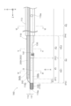
- FIG. 2 shows an enlarged side view of the distal end portion of the IVUS catheter 100
- FIG. 3 shows an enlarged side view (lower surface) of the IVUS catheter 100 viewed from direction A in FIG. 4
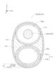
- FIG. 4 shows the cross-sectional configuration of IVUS catheter 100 at position IV-IV in FIG. 2
- FIG. 5 shows the cross-sectional configuration of IVUS catheter 100 at position VV in FIG. 6 shows the cross-sectional configuration of IVUS catheter 100 at location VI-VI of FIG.
- the IVUS catheter 100 is an elongated medical device used when performing IVUS, which is a technique for acquiring images inside biological lumens such as blood vessels.
- the IVUS catheter 100 has an elongated shaft portion 110 .
- shaft portion 110 includes first inner shaft 111 , second inner shaft 112 and outer shaft 113 .
- the first inner shaft 111 is an example of the first shaft in the claims
- the second inner shaft 112 is an example of the second shaft in the claims.
- the second inner shaft 112 is a substantially cylindrical member having an IVUS lumen 160L into which the IVUS device 200 is inserted.
- a distal end second opening 110b that communicates the IVUS lumen 160L with the outside is formed at the distal end of the second inner shaft 112, and a proximal end of the second inner shaft 112 communicates the IVUS lumen 160L with the outside.
- a proximal second opening 110d is formed (FIG. 1).
- the distal second opening 110b is an opening for discharging the fluid injected into the IVUS lumen 160L from the proximal second opening 110d.
- the tip second opening 110 b does not have to be formed at the tip of the second inner shaft 112 , and may be formed at the tip of the second inner shaft 112 .
- IVUS lumen 160L is an example of an imaging lumen in the claims.
- the first inner shaft 111 is a substantially cylindrical member having a guidewire lumen 150L into which a guidewire is inserted.
- the distal end of the first inner shaft 111 is formed with a distal first opening 110a that communicates the guide wire lumen 150L with the outside.
- a communicating proximal end first opening 110c is formed (FIG. 1).
- the first inner shaft 111 and the second inner shaft 112 are arranged side by side in the Y-axis direction with their extending directions parallel to each other. As shown in FIG. 2, the most distal end of first inner shaft 111 (hereinafter referred to as “protruding portion 115”) protrudes forward from third position P3, which is the position of the distal end of second inner shaft 112. there is Therefore, the tip first opening 110a is positioned closer to the tip side than the tip second opening 110b.
- the distal end portion of the second inner shaft 112 has a shape in which the outer diameter gradually decreases from the proximal end side to the distal end side, and the distal end surface is smoothly connected to the projecting portion 115 of the first inner shaft 111 . .
- a distal tip 120 is joined to at least a portion of the projecting portion 115 of the first inner shaft 111 .
- the distal tip 120 is made of, for example, a radiopaque material.
- the shape of the distal tip 120 can be set arbitrarily. For example, it may be a substantially cylindrical shape with an R at the distal end, or a substantially truncated cone shape whose outer diameter gradually decreases from the proximal side to the distal side. be able to.
- a part of the second inner shaft 112 along its extending direction is joined to the first inner shaft 111 , and the remaining part is not joined to the first inner shaft 111 . More specifically, as shown in FIG. 2, a portion of the shaft portion 110 on the distal side, specifically, the first position P1 located on the proximal side from the distal end of the second inner shaft 112, is shifted from the first position P1 to the first position P1.
- the second inner shaft 112 is not joined to the first inner shaft 111 in the first region R1 up to the second position P2 located on the proximal side.
- the length of the first region R1 along the extending direction of the shaft portion 110 can be, for example, 10 mm to 30 mm.
- the second region R2 which is continuous with the first region R1 and located on the proximal side of the first region R1, specifically, the region from the second position P2 to the proximal end of the second inner shaft 112
- the second inner shaft 112 is joined to the first inner shaft 111 .
- a third region R3 that is continuous with the first region R1 and located on the tip side of the first region R1, specifically, from the first position P1 to the third position P3 that is the tip of the second inner shaft 112.
- the second inner shaft 112 is joined to the first inner shaft 111 in the region of .
- the joint portion where the second inner shaft 112 is joined to the first inner shaft 111 and the non-joint portion where the second inner shaft 112 is not joined to the first inner shaft 111 are provided.
- Three parts, a joint portion and another joint portion where the second inner shaft 112 is joined to the first inner shaft 111, are arranged in order from the distal end side to the proximal end side.
- joining between resins by heat melting or joining with an insulating adhesive such as an epoxy adhesive can be adopted.
- an insulating adhesive such as an epoxy adhesive
- the joining of the first inner shaft 111 and the second inner shaft 112 is realized by welding. Therefore, in the first region R1 where the first inner shaft 111 and the second inner shaft 112 are not joined, as shown in FIG. As shown in FIGS. 5 and 6, the second region R2 has a flattened distorted cross section due to welding.
- the second inner shaft 112 has a single-layer structure over its entire length.
- the first inner shaft 111 has a single-layer structure consisting of only the first layer 111a in the third region R3 and the first region R1. It is a two-layer structure consisting of In this embodiment, the thickness t111a of the first layer 111a is substantially the same as the thickness t111b of the second layer 111b.
- the outer shaft 113 is a substantially elliptical cylindrical member.
- the inner space of outer shaft 113 accommodates first inner shaft 111 and second inner shaft 112 .
- a filling material 116 is filled around the first inner shaft 111 and the second inner shaft 112 in the inner space of the outer shaft 113 , thereby fixing the first inner shaft 111 and the second inner shaft 112 .
- the distal end of the outer shaft 113 is positioned at a fourth position P4, which is closer to the proximal side than the second position P2.
- the outer shaft 113 does not cover the first inner shaft 111 and the second inner shaft 112 in the fourth region R4, which is the region from the third position P3 to the fourth position P4, and is continuous with the fourth region R4.
- the first inner shaft 111 and the second inner shaft 112 are covered in the fifth region R5 located on the proximal side of the fourth region R4.
- the fourth region R4 is a region that includes the first region R1.
- the region from the third position P3 to the second position P2 will be referred to as a first small region R41
- the region from the second position P2 to the fourth position P4 will be referred to as a second small region R42.
- the minimum thickness of the shaft portion 110 at the position of the guidewire lumen 150L differs depending on the position along the extending direction.
- the minimum value of the thickness of the shaft portion 110 at the position of the guide wire lumen 150L means that the thickness of the shaft portion 110 from the inner peripheral surface of the guide wire lumen 150L to the shaft portion 110 in the cross section of the shaft portion 110 (see FIGS. 4 to 6). It is the shortest distance to the outer peripheral surface of the guide wire, and is hereinafter referred to as the "minimum thickness of the shaft on the lumen side of the guide wire".
- the first small region R41 the third region R3 and the first region R1 of the fourth region R4 as shown in FIG.
- the guide wire lumen side shaft portion thickness minimum value increases in the order of the first small region R41, the second small region R42, and the fifth region R5. That is, the guidewire lumen-side shaft portion thickness minimum value gradually increases from the distal side toward the proximal side.
- the first inner shaft 111 is formed with a notch 130 that communicates the guide wire lumen 150L with the outside.
- Notch 130 is located in second region R2 (more specifically, second small region R42) described above.
- the notch 130 is formed on the side surface of the first inner shaft 111 at a position opposite to the IVUS lumen 160L with respect to the central axis O of the guide wire lumen 150L.
- the notch 130 has a major axis extending in the extending direction (Z-axis direction) of the first inner shaft 111 when viewed in the direction (Y-axis direction) in which the guide wire lumen 150L and the IVUS lumen 160L are arranged. It has a substantially elliptical shape.
- a marker 141 made of, for example, a radiopaque material is provided in the vicinity of the notch 130 (on the distal end side of the notch 130 in this embodiment).
- the IVUS lumen 160L formed in the second inner shaft 112 extends along the central axis of the second inner shaft 112 from the distal end of the second inner shaft 112 to the proximal end.
- the guide wire lumen 150L formed in the first inner shaft 111 similarly extends along the central axis of the first inner shaft 111 from the distal end to the proximal end of the first inner shaft 111. However, it branches at an intermediate position (for example, a position separated from the tip by about 200 mm to 400 mm) and communicates with the outside through a port 110e formed on the side surface of the shaft portion 110.
- branched lumen 150Lb a lumen branched from the guidewire lumen 150L and connected to the port 110e.
- branch portion 150 the portion around the connection between the guide wire lumen 150L and the branch lumen 150Lb is referred to as a "branch portion 150".
- the branch portion 150 has a large-diameter portion 151 , a raised portion 152 and a boundary wall 153 .
- the large-diameter portion 151 is a portion having a larger inner diameter than other portions of the guidewire lumen 150L.
- the raised portion 152 is a raised portion of the inner peripheral surface 152i of the inner peripheral surface of the branch portion 150 that defines the guidewire lumen 150L.
- the raised portion 152 is provided on the inner peripheral surface 152i of the branch portion 150 on the distal end side of the large diameter portion 151 . In the raised portion 152, the inner peripheral surface 152i of the branched portion 150 is raised toward the side where the branched lumen 150Lb extends.
- the boundary wall 153 is a portion of the shaft portion 110 provided closer to the proximal side than the large diameter portion 151, and is a portion that separates the guide wire lumen 150L and the branch lumen 150Lb.
- the tip A1 of the boundary wall 153 is located on the tip side of the tip A2 of the port 110e.
- FIG. 7 is an explanatory diagram showing an example of how the IVUS catheter 100 is used.
- Column (A) in FIG. 7 shows a side view of the IVUS catheter 100 viewed from the same direction as in FIG. 2, and column (B) in FIG. 7 shows an IVUS catheter viewed from the same direction as in FIG. A side (bottom) view of catheter 100 is shown.
- a delivery guide wire 70 used for delivery of the IVUS catheter 100 is inserted into the guide wire lumen 150L from the distal end first opening 110a, and proceeds through the guide wire lumen 150L from the distal side to the proximal side.
- the IVUS catheter 100 is used as a rapid exchange type (Rx type) catheter, hereinafter referred to as "first case".
- Rx type rapid exchange type
- the operator inserts the proximal end of the delivery guide wire 70 into the guide wire lumen 150L from the distal end first opening 110a of the IVUS catheter 100, and from the port 110e through the branch lumen 150Lb. pull out to the outside.
- the base end portion of the delivery guide wire 70 is naturally guided toward the branch lumen 150Lb (advance in the direction of the thick arrow) by contacting the raised portion 152 .
- FIG. 8 is an explanatory diagram showing another example of usage of the IVUS catheter 100.
- FIG. Column (A) in FIG. 8 shows a side view of the IVUS catheter 100 viewed from the same direction as in FIG. 2, and column (B) in FIG. 8 shows an IVUS catheter viewed from the same direction as in FIG. A side (bottom) view of catheter 100 is shown.
- a penetrating guidewire 400 used for penetrating a CTO lesion for example, is inserted into the guidewire lumen 150L from the proximal first opening 110c (FIG. 1), and passes through the guidewire lumen 150L from the proximal side.
- Mode of use of the IVUS catheter 100 when advancing toward the distal side in other words, when the IVUS catheter 100 is used as an over-the-wire type (OTW type) catheter, hereinafter referred to as the "second case"). is shown.
- OGW type over-the-wire type
- the operator inserts the distal end portion of the penetrating guidewire 400 into the guidewire lumen 150L from the proximal end first opening 110c, and straightly advances it so as to pass through the bifurcated portion 150 (bifurcated portion).
- the penetrating guide wire 400 is pulled out from the notch 130 without straying into the lumen 150Lb.
- the distal end of the penetrating guide wire 400 contacts the boundary wall 153 and is naturally guided to pass through the bifurcation 150 (advance in the direction of the thick arrow).
- IVUS catheter 100 further comprises regulator 105 .
- the adjuster 105 is the part that operates to advance or retract the IVUS device 200 in the IVUS lumen 160L.
- the adjuster 105 has, for example, a dial that can be operated by the operator, and the IVUS device 200 advances or retreats when the dial is rotated.
- Outer shaft 113, first inner shaft 111, second inner shaft 112, filler 116 and regulator 105 are made of, for example, nylon resin such as polyamide, polyolefin such as polyethylene, polypropylene, ethylene-propylene copolymer, polyethylene terephthalate. Polyesters such as polyvinyl chloride, ethylene-vinyl acetate copolymers, cross-linked ethylene-vinyl acetate copolymers, thermoplastic resins such as polyurethane, polyamide elastomers, polyolefin elastomers, polyurethane elastomers, silicone rubbers, latex rubbers, etc. material.
- nylon resin such as polyamide
- polyolefin such as polyethylene, polypropylene, ethylene-propylene copolymer, polyethylene terephthalate.
- Polyesters such as polyvinyl chloride, ethylene-vinyl acetate copolymers, cross-linked ethylene-vinyl acetate copoly
- Outer shaft 113, first inner shaft 111, second inner shaft 112, filler 116 and adjuster 105 may be made of the same material, or at least some or all of them may be made of different materials. may be formed. At least a portion of outer shaft 113, first inner shaft 111, second inner shaft 112, and filler 116 near cutout 130 is made of a resin having a small difference in acoustic impedance from living tissue, such as It is preferably made of polyethylene.
- FIG. 9 is an explanatory diagram schematically showing the configuration of the IVUS device 200.
- the IVUS device 200 is a device for acquiring an image inside a biological lumen, and has an elongated external shape as a whole.
- IVUS device 200 is an example of an imaging device in the claims.
- the IVUS device 200 has a transducer 201 , a driving cable 202 , a connector 203 and a motor drive 204 .
- the transducer 201 has an ultrasonic probe (also called an ultrasonic transducer, piezoelectric body, ultrasonic transmitting/receiving element, or ultrasonic element) that transmits ultrasonic waves and receives the reflected waves.
- a motor drive 204 is a device for controlling the rotation of the transducer 201 .
- Motor drive 204 is electrically connected to imaging console 300 via cable 50 (FIG. 1).
- Driving cable 202 is an elongated member and has a coaxial line that electrically connects transducer 201 and motor drive 204 .
- Connector 203 is a member for connecting the coaxial line of driving cable 202 and motor drive 204 .
- the imaging console 300 (FIG. 1) is a device that controls the IVUS device 200 and generates and displays images based on signals received from the IVUS device 200. Specifically, the imaging console 300 moves the transducer 201 in the IVUS lumen 160L in the extension direction (Z-axis direction) of the shaft portion 110 and in the circumferential direction of the shaft portion 110 in accordance with the operation of the adjuster 105. rotate to The range of movement of the transducer 201 along the extending direction of the shaft portion 110 can be set, for example, from the tip of the second inner shaft 112 to a position separated from the tip by about 100 mm to 200 mm.
- the imaging console 300 causes the transducer 201 to transmit and receive ultrasonic waves in accordance with an operator's operation via input means (not shown). Reflected waves received by transducer 201 are input to imaging console 300 via driving cable 202 and cable 50 .
- the imaging console 300 generates an image represented by gradation of light and shade according to the intensity of the received reflected wave, and causes the display 302 to display the generated image.
- the image acquired by the IVUS device 200 and displayed on the display 302 will also be referred to as a "sensor image”.
- FIG. 10 and 11 show a coronary artery 80 as an example of a biological lumen, a CTO 81 generated in the coronary artery 80, a true lumen 84, and a false lumen 82 formed in or under the intima of the coronary artery 80 (delivery All dissected lumens other than the true lumen 84 formed by a medical device such as a guidewire 70) and the fibrous capsule (plaque) 83 that exists between the true lumen 84 and the false lumen 82 are shown.
- the fibrous coating 83 may be formed in a fibrous form on the surface of the CTO lesion.
- FIG. 10 shows how the delivery guide wire 70 is inserted into the coronary artery 80 .
- the delivery guide wire 70 operated by the operator has erroneously entered the intima of the coronary artery 80 or has formed a false lumen 82 under the intima.
- FIG. 10 shows how the IVUS catheter 100 is delivered using the delivery guide wire 70 .
- the operator inserts the delivery guide wire 70 into the IVUS catheter 100 by performing the operation described above with reference to FIG.
- the operator then delivers the IVUS catheter 100 to the false lumen 82 using the delivery guidewire 70 as a guide.
- the transducer 201 of the IVUS device 200 is placed in the first region R1 of the IVUS catheter 100 .
- FIG. 11 shows how the positions of the delivered IVUS catheter 100 and IVUS device 200 are adjusted. The operator adjusts each position shown in the following a1 to a3. Note that the adjustment a2 may be omitted.
- Adjustment a1 Position adjustment along the extending direction of the IVUS catheter 100
- the operator moves the IVUS catheter 100 along the coronary artery 80 to position the notch 130 of the IVUS catheter 100 in an optimal position for penetration of the penetrating guidewire 400 into the true lumen 84.
- the adjustment a1 can be performed while confirming the position of the coronary artery 80 on the sensor image or the position of the marker 141 on the X-ray image.
- This adjustment is performed, for example, in order to make it easier to confirm the position (the position of the tip of the CTO 81) to be penetrated by the penetrating guide wire 400 pulled out from the notch 130 by using the sensor image, the first region of the IVUS catheter 100 Execution is performed so that R1 is positioned at the tip of CTO81. At this time, by referring to the sensor image based on the signal from the transducer 201 located in the first region R1, while confirming the position of the tip of the CTO 81, the first region R1 comes to the position of the tip of the CTO 81. Moreover, the position along the extension direction of the IVUS catheter 100 can be adjusted with high accuracy.
- Adjustment a2 Adjusting the orientation of the IVUS catheter 100 along the circumferential direction
- the operator By rotating the IVUS catheter 100 in the circumferential direction, the operator adjusts the orientation of the IVUS catheter 100 so that the notch 130 faces the CTO 81 .
- the adjustment a2 can be performed while confirming the positional relationship between the delivery guide wire 70 and the coronary artery 80 on the sensor image.
- Adjustment a3 Adjusting the position along the longitudinal direction of the transducer 201 of the IVUS device 200
- the operator operates the adjuster 105 to move the transducer 201 so that the position of the transducer 201 is suitable for observing the penetration of the penetrating guidewire 400 .
- the adjustment a3 can be performed while confirming the coronary artery 80 on the sensor image.
- the (B) column of FIG. 11 shows how the penetrating guidewire 400 penetrates the living tissue.
- the penetrating guidewire 400 is an elongated medical device having a pointed end.
- the pointed portion of the penetrating guide wire 400 is an arrow-shaped or wedge-shaped portion that decreases in diameter from the proximal side toward the distal side, and allows the penetrating guide wire 400 to penetrate living tissue.
- the pointed portion of the penetrating guide wire 400 is used to penetrate the biological tissue (target tissue), and the distal end of the penetrating guide wire 400 reaches the true cavity 84 .
- the transducer 201 of the IVUS device 200 is arranged in the first region R1 of the IVUS catheter 100 so that the penetration position of the penetration guidewire 400 can be easily confirmed by the sensor image.
- Such a method enables opening of the CTO 81 by the recanalization catheter system 10.
- the method described above is merely an example, and the recanalization catheter system 10 can be used in various procedures.
- the recanalization catheter system 10 can be used not only for the approach from the false lumen 82 to the true lumen 84, but also for the approach through the CTO from the proximal true lumen 84 to the distal true lumen 84. may be
- the IVUS catheter 100 of this embodiment includes the shaft portion 110 having the first inner shaft 111 and the second inner shaft 112 .
- the first inner shaft 111 is a tubular member having a guidewire lumen 150L into which a guidewire is inserted.
- the second inner shaft 112 is a tubular member having an IVUS lumen 160L into which the IVUS device 200 is inserted, and arranged side by side with the first inner shaft 111 .
- the second inner shaft 112 is joined to the first inner shaft 111 in the first region R1 from the first position P1 at the distal end of the shaft portion 110 to the second position P2 located on the proximal side of the first position P1.
- the second inner shaft 112 is joined to the first inner shaft 111 in a second region R2 that is continuous with the first region R1 and positioned closer to the proximal side than the first region R1.
- the first region R1 where the second inner shaft 112 is not joined to the first inner shaft 111 exists at the distal end of the shaft portion 110 .
- the first region R1 there is no adhesive for bonding the first inner shaft 111 and the second inner shaft 112 together, and the first inner shaft 111 and the second inner shaft 112 are heat-sealed. No distortion occurred. Therefore, when the transducer 201 of the IVUS device 200 is positioned in the first region R1, the presence of the adhesive does not prevent the transducer 201 from transmitting and receiving ultrasonic waves on the first inner shaft 111 side. Further, as shown in FIG.
- the range (the range of the angle ⁇ 1 shown in FIGS. 4 and 5) in which the transmission and reception of ultrasonic waves on the first inner shaft 111 side by the transducer 201 of the IVUS device 200 is blocked is narrower than the location where the angle ⁇ 1 is located. Therefore, according to the IVUS catheter 100 of the present embodiment, the joining of the first inner shaft 111 and the second inner shaft 112 prevents the transducer 201 from transmitting and receiving ultrasonic waves on the first inner shaft 111 side. is avoided, and acquisition of clearer images by the IVUS device 200 can be achieved.
- the transducer 201 when the transducer 201 is placed in the first region R1 of the IVUS catheter 100 during delivery of the IVUS catheter 100 or during penetration by the penetrating guidewire 400, the first region
- the sensor image based on the signal from the transducer 201 located at R1 the position of the tip of the CTO 81 can be confirmed with high accuracy, and the IVUS catheter 100 can be delivered to an appropriate position. It is possible to accurately confirm the penetration position of the wire 400 and whether or not the penetration guide wire 400 has surely penetrated the CTO 81 .
- the second inner shaft 112 is provided at the distal end portion of the shaft portion 110, which tends to become stiff when the IVUS device 200 is inserted, although flexibility is required. Due to the presence of the first region R1 that is not joined to the first inner shaft 111, the flexibility of the shaft portion 110 can be improved, and the operability of the IVUS catheter 100 can be improved.
- a large opening (a portion where no resin material exists) is provided at a position facing the transducer 201 in the first inner shaft in order to obtain a clearer image.
- the rigidity gap of the shaft portion 110 can be reduced, and the kink resistance of the shaft portion 110 can be improved.
- the first position P1 is located on the proximal side of the distal end of the second inner shaft 112, continues to the first region R1, and is located on the distal side of the first region R1.
- the second inner shaft 112 is joined to the first inner shaft 111 in the third region R3. Therefore, according to the IVUS catheter 100 of the present embodiment, the existence of the first region R1 in which the second inner shaft 112 is not joined to the first inner shaft 111 enables acquisition of a clearer image while The shaft portion is caused by the provision of the unjoined first region R1 due to the presence of the third region R3, which is located on the distal side of the first region R1 and where the second inner shaft 112 is joined to the first inner shaft 111. It is possible to suppress deterioration of the operability of 110 .
- the guidewire lumen side shaft portion thickness minimum value in the fourth region R4 including the first region R1 is continuous to the fourth region R4 and is greater than the fourth region R4. is smaller than the guidewire lumen side shaft portion thickness minimum value in the fifth region R5 located on the proximal side. Therefore, when the transducer 201 is positioned in a portion other than the first region R1 in the fourth region R4, even if the transducer 201 is not in the first region R1, compared to the case where the transducer 201 is positioned in the fifth region R5, the transducer 201 is suppressed from obstructing the transmission and reception of ultrasonic waves on the first inner shaft 111 side.
- the transducer 201 by positioning the transducer 201 in the fourth region R4, transmission and reception of ultrasonic waves on the first inner shaft 111 side (guide wire lumen 150L side) by the transducer 201 can be performed. Obstruction can be avoided more effectively, and sharper image acquisition by the IVUS device 200 can be achieved.
- the transducer 201 is placed in a portion of the fourth region R4 other than the first region R1, instead of the first region R1. Even if it is, by referring to the sensor image based on the signal from the transducer 201, the position of the tip of the CTO 81 can be accurately confirmed and the IVUS catheter 100 can be delivered to the appropriate position. , the penetration position by the penetrating guide wire 400 and whether or not the penetrating guide wire 400 has certainly penetrated the CTO 81 can be confirmed with high accuracy.
- the fourth region R4 includes a first small region R41 and a second small region continuous with the first small region R41 and positioned closer to the proximal side than the first small region R41.
- the guidewire lumen side shaft portion thickness minimum value in the second small region R42 is larger than the guidewire lumen side shaft portion thickness minimum value in the first small region R41. Therefore, according to the IVUS catheter 100 of the present embodiment, the rigidity of the shaft portion 110 in the second subregion R42 can be increased, and, for example, the rigidity can be ensured when the bent portion in the blood vessel is advanced. .
- the rigidity of the shaft portion 110 can be gradually decreased in the order of the fifth region R5, the second small region R42, and the first small region R41, which are aligned from the proximal side toward the distal side, and the rigidity gap can be effectively reduced. It is possible to effectively improve the kink resistance of the shaft portion 110 by reducing it.
- FIG. 12 is an explanatory diagram schematically showing the configuration of the IVUS catheter 100a in the second embodiment.
- the same configurations as those of the IVUS catheter 100 of the first embodiment described above are denoted by the same reference numerals, and description thereof will be omitted as appropriate.
- the IVUS catheter 100a of the second embodiment differs from the IVUS catheter 100 of the first embodiment in the position of the first region R1 where the second inner shaft 112 is not joined to the first inner shaft 111.
- the first region R1 is set to include part of the notch 130 formed in the shaft portion 110 on the distal end side. That is, in the IVUS catheter 100a of the second embodiment, the second inner shaft 112 is not joined to the first inner shaft 111 at a part of the notch 130 on the distal side. Therefore, the IVUS device 200 can acquire a clear image near the notch 130 .
- a clear image obtained by the IVUS device 200 can be referred to perform a procedure. can improve convenience.
- FIG. 13 is an explanatory diagram schematically showing the configuration of an IVUS catheter 100b according to the third embodiment.
- the same configurations as those of the IVUS catheter 100 of the first embodiment described above are denoted by the same reference numerals, and description thereof will be omitted as appropriate.
- the IVUS catheter 100b of the third embodiment differs from the IVUS catheter 100 of the first embodiment in that it has three lumens.
- the shaft portion 110 of the IVUS catheter 100b of the third embodiment is a first inner shaft 111 having a guidewire lumen (delivery guidewire lumen) 150L into which the delivery guidewire 70 (see FIG. 7) is inserted.
- a guide wire lumen (penetration guide wire lumen) 170L into which the penetration guide wire 400 (see FIG. 8) is inserted.
- a third inner shaft 30 is provided.
- the third inner shaft 30 is an example of a third shaft in the claims.
- the third inner shaft 30 is a substantially cylindrical member.
- the tip of the third inner shaft 30 is positioned closer to the proximal side than the tip of the first inner shaft 111 and the tip of the second inner shaft 112 .
- the distal end of the third inner shaft 30 is formed with a distal third opening 30a that communicates the guide wire lumen 170L with the outside.
- the first inner shaft 111 , the second inner shaft 112 and the third inner shaft 30 are arranged side by side with their extension directions parallel to each other, and are accommodated in the inner space of the outer shaft 113 .
- the notch 130 is not formed in the first inner shaft 111 .
- the first position P1 at the distal end of the shaft portion 110 is located on the proximal side of the first position P1.
- the second inner shaft 112 is not joined to the first inner shaft 111, and is continuous with the first region R1 and positioned closer to the proximal side than the first region R1.
- the second inner shaft 112 is joined to the first inner shaft 111 in the second region R2. Therefore, according to the IVUS catheter 100b of the third embodiment, the joining of the first inner shaft 111 and the second inner shaft 112 prevents the transducer 201 from transmitting and receiving ultrasonic waves on the first inner shaft 111 side.
- the IVUS device 200 can obtain clearer images.
- the first position P1 is located on the proximal side from the distal end of the second inner shaft 112, and the first region
- the second inner shaft 112 is joined to the first inner shaft 111 in a third region R3 that is continuous with R1 and located on the distal end side of the first region R1.
- the presence of the first region R1 in which the second inner shaft 112 is not joined to the first inner shaft 111 enables acquisition of a clearer image, Shaft resulting from provision of the unjoined first region R1 due to the existence of the third region R3 where the second inner shaft 112 is joined to the first inner shaft 111, which is located on the distal side of the first region R1.
- a decrease in operability of the unit 110 can be suppressed.
- the configuration of the recanalization catheter system 10 and the devices such as the IVUS catheter 100 constituting the recanalization catheter system 10 in the above embodiment is merely an example, and various modifications are possible.
- the third region R3 where the second inner shaft 112 is joined to the first inner shaft 111 is present on the distal end side of the first region R1 where the second inner shaft 112 is not joined to the first inner shaft 111. It is also possible that the region R3 does not exist and the tip of the second inner shaft 112 is not joined to the first inner shaft 111 .
- the minimum thickness of the guidewire lumen side shaft portion in the second small region R42 is greater than the minimum thickness of the guidewire lumen side shaft portion in the first small region R41. It may be reversed, or both may be the same. In the above embodiment, the minimum guidewire lumen side shaft thickness in the fourth region R4 is smaller than the guidewire lumen side shaft minimum thickness in the fifth region R5. It may be reversed, or both may be the same.
- first inner shaft 111 and the second inner shaft 112 are formed from a single cylindrical body from the distal end to the proximal end. Alternatively, a plurality of cylindrical bodies arranged in the stretching direction may be connected to each other. Further, although the first inner shaft 111 and the second inner shaft 112 are covered with the outer shaft 113 in the above embodiment, the outer shaft 113 may be omitted.
- the notch 130 is formed in the IVUS catheter 100 in the above embodiment, the notch 130 may not be formed.
- the raised portion 152 and the boundary wall 153 are formed in the bifurcation portion 150 of the IVUS catheter 100, but the raised portion 152 and/or the boundary wall 153 may not be formed.
- the IVUS catheter 100 is formed with the branch lumen 150Lb branching from the guidewire lumen 150L, but the branch lumen 150Lb may not be formed.
- the IVUS device 200 is used as the imaging device, but instead of the IVUS device 200, other imaging devices such as OCT (Optical Coherence Tomography) devices and cameras may be used. good.
- OCT Optical Coherence Tomography
- the recanalization catheter system 10 is a system for using the penetrating guidewire 400, but without using the penetrating guidewire 400, ablation of biological tissue using plasma is performed. It may be configured as a system for opening the CTO using a plasma guidewire. Recanalization catheter system 10 may also be used in other ways not described above. For example, the recanalization catheter system 10 may be used in blood vessels other than coronary arteries (for example, cerebral vessels, etc.), may be used in biological lumens other than blood vessels, and may be used for other treatments and examinations than opening the CTO. may be used for
Landscapes
- Health & Medical Sciences (AREA)
- Life Sciences & Earth Sciences (AREA)
- Animal Behavior & Ethology (AREA)
- Biophysics (AREA)
- Veterinary Medicine (AREA)
- Public Health (AREA)
- General Health & Medical Sciences (AREA)
- Engineering & Computer Science (AREA)
- Biomedical Technology (AREA)
- Heart & Thoracic Surgery (AREA)
- Pathology (AREA)
- Molecular Biology (AREA)
- Surgery (AREA)
- Medical Informatics (AREA)
- Radiology & Medical Imaging (AREA)
- Physics & Mathematics (AREA)
- Nuclear Medicine, Radiotherapy & Molecular Imaging (AREA)
- Pulmonology (AREA)
- Anesthesiology (AREA)
- Hematology (AREA)
- Media Introduction/Drainage Providing Device (AREA)
Priority Applications (2)
| Application Number | Priority Date | Filing Date | Title |
|---|---|---|---|
| JP2023573972A JPWO2023136140A1 (https=) | 2022-01-13 | 2022-12-27 | |
| US18/768,032 US20240358348A1 (en) | 2022-01-13 | 2024-07-10 | Catheter |
Applications Claiming Priority (2)
| Application Number | Priority Date | Filing Date | Title |
|---|---|---|---|
| JP2022003556 | 2022-01-13 | ||
| JP2022-003556 | 2022-01-13 |
Related Child Applications (1)
| Application Number | Title | Priority Date | Filing Date |
|---|---|---|---|
| US18/768,032 Continuation US20240358348A1 (en) | 2022-01-13 | 2024-07-10 | Catheter |
Publications (1)
| Publication Number | Publication Date |
|---|---|
| WO2023136140A1 true WO2023136140A1 (ja) | 2023-07-20 |
Family
ID=87279109
Family Applications (1)
| Application Number | Title | Priority Date | Filing Date |
|---|---|---|---|
| PCT/JP2022/048249 Ceased WO2023136140A1 (ja) | 2022-01-13 | 2022-12-27 | カテーテル |
Country Status (3)
| Country | Link |
|---|---|
| US (1) | US20240358348A1 (https=) |
| JP (1) | JPWO2023136140A1 (https=) |
| WO (1) | WO2023136140A1 (https=) |
Cited By (1)
| Publication number | Priority date | Publication date | Assignee | Title |
|---|---|---|---|---|
| WO2026003950A1 (ja) * | 2024-06-25 | 2026-01-02 | 朝日インテック株式会社 | 医療デバイス |
Citations (7)
| Publication number | Priority date | Publication date | Assignee | Title |
|---|---|---|---|---|
| JP2005510301A (ja) * | 2001-11-21 | 2005-04-21 | メデイカル コンポーネンツ,インコーポレーテツド | マルチルーメン・カテーテルおよびそのカテーテルの製造方法 |
| JP2009261521A (ja) * | 2008-04-23 | 2009-11-12 | Olympus Medical Systems Corp | 内視鏡用ガイドワイヤプローブ、ガイドワイヤプローブセット、及び超音波内視鏡 |
| US20170079671A1 (en) * | 2015-09-22 | 2017-03-23 | Medtronic Vascular, Inc. | Occlusion Bypassing Apparatus With a Re-Entry Needle and a Stabilization Tube |
| JP2018033697A (ja) * | 2016-08-31 | 2018-03-08 | テルモ株式会社 | 医療用デバイス |
| JP2018121701A (ja) * | 2017-01-30 | 2018-08-09 | テルモ株式会社 | 医療デバイス |
| JP2020116038A (ja) * | 2019-01-22 | 2020-08-06 | テルモ株式会社 | カテーテル |
| JP2021529588A (ja) * | 2018-06-28 | 2021-11-04 | コーニンクレッカ フィリップス エヌ ヴェKoninklijke Philips N.V. | 内部的に超音波支援された治療薬の局所的送達 |
Family Cites Families (1)
| Publication number | Priority date | Publication date | Assignee | Title |
|---|---|---|---|---|
| EP3777950A4 (en) * | 2018-03-29 | 2021-12-15 | Asahi Intecc Co., Ltd. | CATHETER AND RE-CHANNELING CATHETER SYSTEM |
-
2022
- 2022-12-27 WO PCT/JP2022/048249 patent/WO2023136140A1/ja not_active Ceased
- 2022-12-27 JP JP2023573972A patent/JPWO2023136140A1/ja active Pending
-
2024
- 2024-07-10 US US18/768,032 patent/US20240358348A1/en active Pending
Patent Citations (7)
| Publication number | Priority date | Publication date | Assignee | Title |
|---|---|---|---|---|
| JP2005510301A (ja) * | 2001-11-21 | 2005-04-21 | メデイカル コンポーネンツ,インコーポレーテツド | マルチルーメン・カテーテルおよびそのカテーテルの製造方法 |
| JP2009261521A (ja) * | 2008-04-23 | 2009-11-12 | Olympus Medical Systems Corp | 内視鏡用ガイドワイヤプローブ、ガイドワイヤプローブセット、及び超音波内視鏡 |
| US20170079671A1 (en) * | 2015-09-22 | 2017-03-23 | Medtronic Vascular, Inc. | Occlusion Bypassing Apparatus With a Re-Entry Needle and a Stabilization Tube |
| JP2018033697A (ja) * | 2016-08-31 | 2018-03-08 | テルモ株式会社 | 医療用デバイス |
| JP2018121701A (ja) * | 2017-01-30 | 2018-08-09 | テルモ株式会社 | 医療デバイス |
| JP2021529588A (ja) * | 2018-06-28 | 2021-11-04 | コーニンクレッカ フィリップス エヌ ヴェKoninklijke Philips N.V. | 内部的に超音波支援された治療薬の局所的送達 |
| JP2020116038A (ja) * | 2019-01-22 | 2020-08-06 | テルモ株式会社 | カテーテル |
Cited By (1)
| Publication number | Priority date | Publication date | Assignee | Title |
|---|---|---|---|---|
| WO2026003950A1 (ja) * | 2024-06-25 | 2026-01-02 | 朝日インテック株式会社 | 医療デバイス |
Also Published As
| Publication number | Publication date |
|---|---|
| JPWO2023136140A1 (https=) | 2023-07-20 |
| US20240358348A1 (en) | 2024-10-31 |
Similar Documents
| Publication | Publication Date | Title |
|---|---|---|
| JP7430209B2 (ja) | 心臓内心エコー法(ice)用カテーテル先端アセンブリ | |
| JP7292448B2 (ja) | 十字状内部輪郭を備える内張り可変ブレード差的デュロメータ硬度複管路シャフト | |
| US12076184B2 (en) | Pullwire crown and crown sleeve for catheter assembly | |
| JP7465824B2 (ja) | カテーテル | |
| CN111918690B (zh) | 导管、以及再开通导管系统 | |
| JP3413175B2 (ja) | 固定型中心コア及び先端を持つ超音波撮像用ガイドワイヤ | |
| US9492140B2 (en) | Devices, systems, and methods for forward looking imaging | |
| US20140257102A1 (en) | Devices, Systems, and Methods for Dual Image Intravascular Ultrasound | |
| WO2022170808A1 (zh) | 一种具有前视能力的血管内超声成像导管及系统 | |
| JP2023004052A (ja) | カテーテル | |
| JP2006020944A (ja) | カテーテル | |
| US20240358348A1 (en) | Catheter | |
| US20180214670A1 (en) | Diagnostic imaging catheter | |
| JP2024077665A (ja) | カテーテル | |
| JP5171985B2 (ja) | 超音波カテーテル | |
| JP7555421B2 (ja) | カテーテル、及び、再開通カテーテルシステム | |
| JP7487319B2 (ja) | カテーテル、及び、再開通カテーテルシステム | |
| WO2025100517A1 (ja) | 画像取得用カテーテル | |
| WO2025100516A1 (ja) | 画像取得用カテーテル | |
| JP2020062079A (ja) | 画像診断用カテーテル | |
| WO2025115167A1 (ja) | 医療デバイス | |
| HK40104095A (zh) | 图像诊断用导管 | |
| JP2018121966A (ja) | 医療用デバイス |
Legal Events
| Date | Code | Title | Description |
|---|---|---|---|
| 121 | Ep: the epo has been informed by wipo that ep was designated in this application |
Ref document number: 22920656 Country of ref document: EP Kind code of ref document: A1 |
|
| ENP | Entry into the national phase |
Ref document number: 2023573972 Country of ref document: JP Kind code of ref document: A |
|
| NENP | Non-entry into the national phase |
Ref country code: DE |
|
| 122 | Ep: pct application non-entry in european phase |
Ref document number: 22920656 Country of ref document: EP Kind code of ref document: A1 |