WO2023136140A1 - Catheter - Google Patents
Catheter Download PDFInfo
- Publication number
- WO2023136140A1 WO2023136140A1 PCT/JP2022/048249 JP2022048249W WO2023136140A1 WO 2023136140 A1 WO2023136140 A1 WO 2023136140A1 JP 2022048249 W JP2022048249 W JP 2022048249W WO 2023136140 A1 WO2023136140 A1 WO 2023136140A1
- Authority
- WO
- WIPO (PCT)
- Prior art keywords
- shaft
- region
- inner shaft
- catheter
- lumen
- Prior art date
Links
Images


Classifications
-
- A—HUMAN NECESSITIES
- A61—MEDICAL OR VETERINARY SCIENCE; HYGIENE
- A61B—DIAGNOSIS; SURGERY; IDENTIFICATION
- A61B8/00—Diagnosis using ultrasonic, sonic or infrasonic waves
- A61B8/12—Diagnosis using ultrasonic, sonic or infrasonic waves in body cavities or body tracts, e.g. by using catheters
Definitions
- the technology disclosed in this specification relates to catheters.
- the second shaft is joined to the first shaft over its entire length. That is, the second shaft is also joined to the first shaft at the location where the transducer of the IVUS device is placed. Therefore, at the junction, transmission and reception of ultrasonic waves by the transducer of the IVUS device inserted into the IVUS lumen of the second shaft is hindered, and acquisition of a clear image by the IVUS device is hindered. More specifically, when the bonding between the first shaft and the second shaft is achieved using an adhesive, the presence of the adhesive prevents the transducer from transmitting and receiving ultrasonic waves on the first shaft side.
- a catheter disclosed herein comprises a shaft portion having a first shaft and a second shaft.
- the first shaft is a tubular member having a guidewire lumen into which a guidewire is inserted.
- the second shaft is a tubular member having an imaging lumen into which an imaging device for acquiring images of the inside of the body lumen is inserted, and is arranged side by side with the first shaft.
- the second shaft is not joined to the first shaft in the first region from the first position at the distal end of the shaft portion to the second position located on the proximal side of the first position.
- the second shaft is joined to the first shaft in a second region that is continuous with the first region and located on the proximal side of the first region.
- Explanatory drawing schematically showing the configuration of the recanalization catheter system in the first embodiment Explanatory diagram showing the configuration of an IVUS catheter Explanatory diagram showing the configuration of an IVUS catheter Explanatory diagram showing the configuration of an IVUS catheter Explanatory diagram showing the configuration of an IVUS catheter Explanatory diagram showing the configuration of an IVUS catheter Explanatory diagram showing an example of usage of an IVUS catheter Explanatory drawing showing another example of the mode of use of the IVUS catheter Explanatory diagram schematically showing the configuration of an IVUS device Explanatory diagram showing an example of how to use the recanalization catheter system Explanatory diagram showing an example of how to use the recanalization catheter system Explanatory drawing schematically showing the configuration of the IVUS catheter in the second embodiment Explanatory drawing schematically showing the configuration of an IVUS catheter in the third embodiment
- FIG. 1 is an explanatory diagram schematically showing the configuration of a recanalization catheter system 10 according to the first embodiment.
- the recanalization catheter system 10 is used, for example, in treating vascular CTO in an antegrade approach.
- the recanalization catheter system 10 includes an IVUS catheter 100 , an IVUS device 200 and an imaging console 300 .
- FIG. 1 shows XYZ axes orthogonal to each other.
- the positive side of the Z-axis is the tip side (distal side) to be inserted into the body, and the negative side of the Z-axis is the proximal side (near side) operated by an operator such as a doctor. position side).
- FIG. 1 shows the IVUS catheter 100 in a substantially linear shape parallel to the Z-axis direction, the IVUS catheter 100 has flexibility to the extent that it can be bent.
- distal end of the recanalization catheter system 10 and its components is referred to as “distal,” the distal end and its vicinity as “distal,” and the proximal end as “proximal.”
- proximal end and its vicinity are referred to as the “base end”.
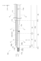
- FIG. 2 shows an enlarged side view of the distal end portion of the IVUS catheter 100
- FIG. 3 shows an enlarged side view (lower surface) of the IVUS catheter 100 viewed from direction A in FIG. 4
- FIG. 4 shows the cross-sectional configuration of IVUS catheter 100 at position IV-IV in FIG. 2
- FIG. 5 shows the cross-sectional configuration of IVUS catheter 100 at position VV in FIG. 6 shows the cross-sectional configuration of IVUS catheter 100 at location VI-VI of FIG.
- the IVUS catheter 100 is an elongated medical device used when performing IVUS, which is a technique for acquiring images inside biological lumens such as blood vessels.
- the IVUS catheter 100 has an elongated shaft portion 110 .
- shaft portion 110 includes first inner shaft 111 , second inner shaft 112 and outer shaft 113 .
- the first inner shaft 111 is an example of the first shaft in the claims
- the second inner shaft 112 is an example of the second shaft in the claims.
- the second inner shaft 112 is a substantially cylindrical member having an IVUS lumen 160L into which the IVUS device 200 is inserted.
- a distal end second opening 110b that communicates the IVUS lumen 160L with the outside is formed at the distal end of the second inner shaft 112, and a proximal end of the second inner shaft 112 communicates the IVUS lumen 160L with the outside.
- a proximal second opening 110d is formed (FIG. 1).
- the distal second opening 110b is an opening for discharging the fluid injected into the IVUS lumen 160L from the proximal second opening 110d.
- the tip second opening 110 b does not have to be formed at the tip of the second inner shaft 112 , and may be formed at the tip of the second inner shaft 112 .
- IVUS lumen 160L is an example of an imaging lumen in the claims.
- the first inner shaft 111 is a substantially cylindrical member having a guidewire lumen 150L into which a guidewire is inserted.
- the distal end of the first inner shaft 111 is formed with a distal first opening 110a that communicates the guide wire lumen 150L with the outside.
- a communicating proximal end first opening 110c is formed (FIG. 1).
- the first inner shaft 111 and the second inner shaft 112 are arranged side by side in the Y-axis direction with their extending directions parallel to each other. As shown in FIG. 2, the most distal end of first inner shaft 111 (hereinafter referred to as “protruding portion 115”) protrudes forward from third position P3, which is the position of the distal end of second inner shaft 112. there is Therefore, the tip first opening 110a is positioned closer to the tip side than the tip second opening 110b.
- the distal end portion of the second inner shaft 112 has a shape in which the outer diameter gradually decreases from the proximal end side to the distal end side, and the distal end surface is smoothly connected to the projecting portion 115 of the first inner shaft 111 . .
- a distal tip 120 is joined to at least a portion of the projecting portion 115 of the first inner shaft 111 .
- the distal tip 120 is made of, for example, a radiopaque material.
- the shape of the distal tip 120 can be set arbitrarily. For example, it may be a substantially cylindrical shape with an R at the distal end, or a substantially truncated cone shape whose outer diameter gradually decreases from the proximal side to the distal side. be able to.
- a part of the second inner shaft 112 along its extending direction is joined to the first inner shaft 111 , and the remaining part is not joined to the first inner shaft 111 . More specifically, as shown in FIG. 2, a portion of the shaft portion 110 on the distal side, specifically, the first position P1 located on the proximal side from the distal end of the second inner shaft 112, is shifted from the first position P1 to the first position P1.
- the second inner shaft 112 is not joined to the first inner shaft 111 in the first region R1 up to the second position P2 located on the proximal side.
- the length of the first region R1 along the extending direction of the shaft portion 110 can be, for example, 10 mm to 30 mm.
- the second region R2 which is continuous with the first region R1 and located on the proximal side of the first region R1, specifically, the region from the second position P2 to the proximal end of the second inner shaft 112
- the second inner shaft 112 is joined to the first inner shaft 111 .
- a third region R3 that is continuous with the first region R1 and located on the tip side of the first region R1, specifically, from the first position P1 to the third position P3 that is the tip of the second inner shaft 112.
- the second inner shaft 112 is joined to the first inner shaft 111 in the region of .
- the joint portion where the second inner shaft 112 is joined to the first inner shaft 111 and the non-joint portion where the second inner shaft 112 is not joined to the first inner shaft 111 are provided.
- Three parts, a joint portion and another joint portion where the second inner shaft 112 is joined to the first inner shaft 111, are arranged in order from the distal end side to the proximal end side.
- joining between resins by heat melting or joining with an insulating adhesive such as an epoxy adhesive can be adopted.
- an insulating adhesive such as an epoxy adhesive
- the joining of the first inner shaft 111 and the second inner shaft 112 is realized by welding. Therefore, in the first region R1 where the first inner shaft 111 and the second inner shaft 112 are not joined, as shown in FIG. As shown in FIGS. 5 and 6, the second region R2 has a flattened distorted cross section due to welding.
- the second inner shaft 112 has a single-layer structure over its entire length.
- the first inner shaft 111 has a single-layer structure consisting of only the first layer 111a in the third region R3 and the first region R1. It is a two-layer structure consisting of In this embodiment, the thickness t111a of the first layer 111a is substantially the same as the thickness t111b of the second layer 111b.
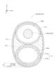
- the outer shaft 113 is a substantially elliptical cylindrical member.
- the inner space of outer shaft 113 accommodates first inner shaft 111 and second inner shaft 112 .
- a filling material 116 is filled around the first inner shaft 111 and the second inner shaft 112 in the inner space of the outer shaft 113 , thereby fixing the first inner shaft 111 and the second inner shaft 112 .
- the distal end of the outer shaft 113 is positioned at a fourth position P4, which is closer to the proximal side than the second position P2.
- the outer shaft 113 does not cover the first inner shaft 111 and the second inner shaft 112 in the fourth region R4, which is the region from the third position P3 to the fourth position P4, and is continuous with the fourth region R4.
- the first inner shaft 111 and the second inner shaft 112 are covered in the fifth region R5 located on the proximal side of the fourth region R4.
- the fourth region R4 is a region that includes the first region R1.
- the region from the third position P3 to the second position P2 will be referred to as a first small region R41
- the region from the second position P2 to the fourth position P4 will be referred to as a second small region R42.
- the minimum thickness of the shaft portion 110 at the position of the guidewire lumen 150L differs depending on the position along the extending direction.
- the minimum value of the thickness of the shaft portion 110 at the position of the guide wire lumen 150L means that the thickness of the shaft portion 110 from the inner peripheral surface of the guide wire lumen 150L to the shaft portion 110 in the cross section of the shaft portion 110 (see FIGS. 4 to 6). It is the shortest distance to the outer peripheral surface of the guide wire, and is hereinafter referred to as the "minimum thickness of the shaft on the lumen side of the guide wire".
- the first small region R41 the third region R3 and the first region R1 of the fourth region R4 as shown in FIG.
- the guide wire lumen side shaft portion thickness minimum value increases in the order of the first small region R41, the second small region R42, and the fifth region R5. That is, the guidewire lumen-side shaft portion thickness minimum value gradually increases from the distal side toward the proximal side.
- the first inner shaft 111 is formed with a notch 130 that communicates the guide wire lumen 150L with the outside.
- Notch 130 is located in second region R2 (more specifically, second small region R42) described above.
- the notch 130 is formed on the side surface of the first inner shaft 111 at a position opposite to the IVUS lumen 160L with respect to the central axis O of the guide wire lumen 150L.
- the notch 130 has a major axis extending in the extending direction (Z-axis direction) of the first inner shaft 111 when viewed in the direction (Y-axis direction) in which the guide wire lumen 150L and the IVUS lumen 160L are arranged. It has a substantially elliptical shape.
- a marker 141 made of, for example, a radiopaque material is provided in the vicinity of the notch 130 (on the distal end side of the notch 130 in this embodiment).
- the IVUS lumen 160L formed in the second inner shaft 112 extends along the central axis of the second inner shaft 112 from the distal end of the second inner shaft 112 to the proximal end.
- the guide wire lumen 150L formed in the first inner shaft 111 similarly extends along the central axis of the first inner shaft 111 from the distal end to the proximal end of the first inner shaft 111. However, it branches at an intermediate position (for example, a position separated from the tip by about 200 mm to 400 mm) and communicates with the outside through a port 110e formed on the side surface of the shaft portion 110.
- branched lumen 150Lb a lumen branched from the guidewire lumen 150L and connected to the port 110e.
- branch portion 150 the portion around the connection between the guide wire lumen 150L and the branch lumen 150Lb is referred to as a "branch portion 150".
- the branch portion 150 has a large-diameter portion 151 , a raised portion 152 and a boundary wall 153 .
- the large-diameter portion 151 is a portion having a larger inner diameter than other portions of the guidewire lumen 150L.
- the raised portion 152 is a raised portion of the inner peripheral surface 152i of the inner peripheral surface of the branch portion 150 that defines the guidewire lumen 150L.
- the raised portion 152 is provided on the inner peripheral surface 152i of the branch portion 150 on the distal end side of the large diameter portion 151 . In the raised portion 152, the inner peripheral surface 152i of the branched portion 150 is raised toward the side where the branched lumen 150Lb extends.
- the boundary wall 153 is a portion of the shaft portion 110 provided closer to the proximal side than the large diameter portion 151, and is a portion that separates the guide wire lumen 150L and the branch lumen 150Lb.
- the tip A1 of the boundary wall 153 is located on the tip side of the tip A2 of the port 110e.
- FIG. 7 is an explanatory diagram showing an example of how the IVUS catheter 100 is used.
- Column (A) in FIG. 7 shows a side view of the IVUS catheter 100 viewed from the same direction as in FIG. 2, and column (B) in FIG. 7 shows an IVUS catheter viewed from the same direction as in FIG. A side (bottom) view of catheter 100 is shown.
- a delivery guide wire 70 used for delivery of the IVUS catheter 100 is inserted into the guide wire lumen 150L from the distal end first opening 110a, and proceeds through the guide wire lumen 150L from the distal side to the proximal side.
- the IVUS catheter 100 is used as a rapid exchange type (Rx type) catheter, hereinafter referred to as "first case".
- Rx type rapid exchange type
- the operator inserts the proximal end of the delivery guide wire 70 into the guide wire lumen 150L from the distal end first opening 110a of the IVUS catheter 100, and from the port 110e through the branch lumen 150Lb. pull out to the outside.
- the base end portion of the delivery guide wire 70 is naturally guided toward the branch lumen 150Lb (advance in the direction of the thick arrow) by contacting the raised portion 152 .
- FIG. 8 is an explanatory diagram showing another example of usage of the IVUS catheter 100.
- FIG. Column (A) in FIG. 8 shows a side view of the IVUS catheter 100 viewed from the same direction as in FIG. 2, and column (B) in FIG. 8 shows an IVUS catheter viewed from the same direction as in FIG. A side (bottom) view of catheter 100 is shown.
- a penetrating guidewire 400 used for penetrating a CTO lesion for example, is inserted into the guidewire lumen 150L from the proximal first opening 110c (FIG. 1), and passes through the guidewire lumen 150L from the proximal side.
- Mode of use of the IVUS catheter 100 when advancing toward the distal side in other words, when the IVUS catheter 100 is used as an over-the-wire type (OTW type) catheter, hereinafter referred to as the "second case"). is shown.
- OGW type over-the-wire type
- the operator inserts the distal end portion of the penetrating guidewire 400 into the guidewire lumen 150L from the proximal end first opening 110c, and straightly advances it so as to pass through the bifurcated portion 150 (bifurcated portion).
- the penetrating guide wire 400 is pulled out from the notch 130 without straying into the lumen 150Lb.
- the distal end of the penetrating guide wire 400 contacts the boundary wall 153 and is naturally guided to pass through the bifurcation 150 (advance in the direction of the thick arrow).
- IVUS catheter 100 further comprises regulator 105 .
- the adjuster 105 is the part that operates to advance or retract the IVUS device 200 in the IVUS lumen 160L.
- the adjuster 105 has, for example, a dial that can be operated by the operator, and the IVUS device 200 advances or retreats when the dial is rotated.
- Outer shaft 113, first inner shaft 111, second inner shaft 112, filler 116 and regulator 105 are made of, for example, nylon resin such as polyamide, polyolefin such as polyethylene, polypropylene, ethylene-propylene copolymer, polyethylene terephthalate. Polyesters such as polyvinyl chloride, ethylene-vinyl acetate copolymers, cross-linked ethylene-vinyl acetate copolymers, thermoplastic resins such as polyurethane, polyamide elastomers, polyolefin elastomers, polyurethane elastomers, silicone rubbers, latex rubbers, etc. material.
- nylon resin such as polyamide
- polyolefin such as polyethylene, polypropylene, ethylene-propylene copolymer, polyethylene terephthalate.
- Polyesters such as polyvinyl chloride, ethylene-vinyl acetate copolymers, cross-linked ethylene-vinyl acetate copoly
- Outer shaft 113, first inner shaft 111, second inner shaft 112, filler 116 and adjuster 105 may be made of the same material, or at least some or all of them may be made of different materials. may be formed. At least a portion of outer shaft 113, first inner shaft 111, second inner shaft 112, and filler 116 near cutout 130 is made of a resin having a small difference in acoustic impedance from living tissue, such as It is preferably made of polyethylene.
- FIG. 9 is an explanatory diagram schematically showing the configuration of the IVUS device 200.
- the IVUS device 200 is a device for acquiring an image inside a biological lumen, and has an elongated external shape as a whole.
- IVUS device 200 is an example of an imaging device in the claims.
- the IVUS device 200 has a transducer 201 , a driving cable 202 , a connector 203 and a motor drive 204 .
- the transducer 201 has an ultrasonic probe (also called an ultrasonic transducer, piezoelectric body, ultrasonic transmitting/receiving element, or ultrasonic element) that transmits ultrasonic waves and receives the reflected waves.
- a motor drive 204 is a device for controlling the rotation of the transducer 201 .
- Motor drive 204 is electrically connected to imaging console 300 via cable 50 (FIG. 1).
- Driving cable 202 is an elongated member and has a coaxial line that electrically connects transducer 201 and motor drive 204 .
- Connector 203 is a member for connecting the coaxial line of driving cable 202 and motor drive 204 .
- the imaging console 300 (FIG. 1) is a device that controls the IVUS device 200 and generates and displays images based on signals received from the IVUS device 200. Specifically, the imaging console 300 moves the transducer 201 in the IVUS lumen 160L in the extension direction (Z-axis direction) of the shaft portion 110 and in the circumferential direction of the shaft portion 110 in accordance with the operation of the adjuster 105. rotate to The range of movement of the transducer 201 along the extending direction of the shaft portion 110 can be set, for example, from the tip of the second inner shaft 112 to a position separated from the tip by about 100 mm to 200 mm.
- the imaging console 300 causes the transducer 201 to transmit and receive ultrasonic waves in accordance with an operator's operation via input means (not shown). Reflected waves received by transducer 201 are input to imaging console 300 via driving cable 202 and cable 50 .
- the imaging console 300 generates an image represented by gradation of light and shade according to the intensity of the received reflected wave, and causes the display 302 to display the generated image.
- the image acquired by the IVUS device 200 and displayed on the display 302 will also be referred to as a "sensor image”.
- FIG. 10 and 11 show a coronary artery 80 as an example of a biological lumen, a CTO 81 generated in the coronary artery 80, a true lumen 84, and a false lumen 82 formed in or under the intima of the coronary artery 80 (delivery All dissected lumens other than the true lumen 84 formed by a medical device such as a guidewire 70) and the fibrous capsule (plaque) 83 that exists between the true lumen 84 and the false lumen 82 are shown.
- the fibrous coating 83 may be formed in a fibrous form on the surface of the CTO lesion.
- FIG. 10 shows how the delivery guide wire 70 is inserted into the coronary artery 80 .
- the delivery guide wire 70 operated by the operator has erroneously entered the intima of the coronary artery 80 or has formed a false lumen 82 under the intima.
- FIG. 10 shows how the IVUS catheter 100 is delivered using the delivery guide wire 70 .
- the operator inserts the delivery guide wire 70 into the IVUS catheter 100 by performing the operation described above with reference to FIG.
- the operator then delivers the IVUS catheter 100 to the false lumen 82 using the delivery guidewire 70 as a guide.
- the transducer 201 of the IVUS device 200 is placed in the first region R1 of the IVUS catheter 100 .
- FIG. 11 shows how the positions of the delivered IVUS catheter 100 and IVUS device 200 are adjusted. The operator adjusts each position shown in the following a1 to a3. Note that the adjustment a2 may be omitted.
- Adjustment a1 Position adjustment along the extending direction of the IVUS catheter 100
- the operator moves the IVUS catheter 100 along the coronary artery 80 to position the notch 130 of the IVUS catheter 100 in an optimal position for penetration of the penetrating guidewire 400 into the true lumen 84.
- the adjustment a1 can be performed while confirming the position of the coronary artery 80 on the sensor image or the position of the marker 141 on the X-ray image.
- This adjustment is performed, for example, in order to make it easier to confirm the position (the position of the tip of the CTO 81) to be penetrated by the penetrating guide wire 400 pulled out from the notch 130 by using the sensor image, the first region of the IVUS catheter 100 Execution is performed so that R1 is positioned at the tip of CTO81. At this time, by referring to the sensor image based on the signal from the transducer 201 located in the first region R1, while confirming the position of the tip of the CTO 81, the first region R1 comes to the position of the tip of the CTO 81. Moreover, the position along the extension direction of the IVUS catheter 100 can be adjusted with high accuracy.
- Adjustment a2 Adjusting the orientation of the IVUS catheter 100 along the circumferential direction
- the operator By rotating the IVUS catheter 100 in the circumferential direction, the operator adjusts the orientation of the IVUS catheter 100 so that the notch 130 faces the CTO 81 .
- the adjustment a2 can be performed while confirming the positional relationship between the delivery guide wire 70 and the coronary artery 80 on the sensor image.
- Adjustment a3 Adjusting the position along the longitudinal direction of the transducer 201 of the IVUS device 200
- the operator operates the adjuster 105 to move the transducer 201 so that the position of the transducer 201 is suitable for observing the penetration of the penetrating guidewire 400 .
- the adjustment a3 can be performed while confirming the coronary artery 80 on the sensor image.
- the (B) column of FIG. 11 shows how the penetrating guidewire 400 penetrates the living tissue.
- the penetrating guidewire 400 is an elongated medical device having a pointed end.
- the pointed portion of the penetrating guide wire 400 is an arrow-shaped or wedge-shaped portion that decreases in diameter from the proximal side toward the distal side, and allows the penetrating guide wire 400 to penetrate living tissue.
- the pointed portion of the penetrating guide wire 400 is used to penetrate the biological tissue (target tissue), and the distal end of the penetrating guide wire 400 reaches the true cavity 84 .
- the transducer 201 of the IVUS device 200 is arranged in the first region R1 of the IVUS catheter 100 so that the penetration position of the penetration guidewire 400 can be easily confirmed by the sensor image.
- Such a method enables opening of the CTO 81 by the recanalization catheter system 10.
- the method described above is merely an example, and the recanalization catheter system 10 can be used in various procedures.
- the recanalization catheter system 10 can be used not only for the approach from the false lumen 82 to the true lumen 84, but also for the approach through the CTO from the proximal true lumen 84 to the distal true lumen 84. may be
- the IVUS catheter 100 of this embodiment includes the shaft portion 110 having the first inner shaft 111 and the second inner shaft 112 .
- the first inner shaft 111 is a tubular member having a guidewire lumen 150L into which a guidewire is inserted.
- the second inner shaft 112 is a tubular member having an IVUS lumen 160L into which the IVUS device 200 is inserted, and arranged side by side with the first inner shaft 111 .
- the second inner shaft 112 is joined to the first inner shaft 111 in the first region R1 from the first position P1 at the distal end of the shaft portion 110 to the second position P2 located on the proximal side of the first position P1.
- the second inner shaft 112 is joined to the first inner shaft 111 in a second region R2 that is continuous with the first region R1 and positioned closer to the proximal side than the first region R1.
- the first region R1 where the second inner shaft 112 is not joined to the first inner shaft 111 exists at the distal end of the shaft portion 110 .
- the first region R1 there is no adhesive for bonding the first inner shaft 111 and the second inner shaft 112 together, and the first inner shaft 111 and the second inner shaft 112 are heat-sealed. No distortion occurred. Therefore, when the transducer 201 of the IVUS device 200 is positioned in the first region R1, the presence of the adhesive does not prevent the transducer 201 from transmitting and receiving ultrasonic waves on the first inner shaft 111 side. Further, as shown in FIG.
- the range (the range of the angle ⁇ 1 shown in FIGS. 4 and 5) in which the transmission and reception of ultrasonic waves on the first inner shaft 111 side by the transducer 201 of the IVUS device 200 is blocked is narrower than the location where the angle ⁇ 1 is located. Therefore, according to the IVUS catheter 100 of the present embodiment, the joining of the first inner shaft 111 and the second inner shaft 112 prevents the transducer 201 from transmitting and receiving ultrasonic waves on the first inner shaft 111 side. is avoided, and acquisition of clearer images by the IVUS device 200 can be achieved.
- the transducer 201 when the transducer 201 is placed in the first region R1 of the IVUS catheter 100 during delivery of the IVUS catheter 100 or during penetration by the penetrating guidewire 400, the first region
- the sensor image based on the signal from the transducer 201 located at R1 the position of the tip of the CTO 81 can be confirmed with high accuracy, and the IVUS catheter 100 can be delivered to an appropriate position. It is possible to accurately confirm the penetration position of the wire 400 and whether or not the penetration guide wire 400 has surely penetrated the CTO 81 .
- the second inner shaft 112 is provided at the distal end portion of the shaft portion 110, which tends to become stiff when the IVUS device 200 is inserted, although flexibility is required. Due to the presence of the first region R1 that is not joined to the first inner shaft 111, the flexibility of the shaft portion 110 can be improved, and the operability of the IVUS catheter 100 can be improved.
- a large opening (a portion where no resin material exists) is provided at a position facing the transducer 201 in the first inner shaft in order to obtain a clearer image.
- the rigidity gap of the shaft portion 110 can be reduced, and the kink resistance of the shaft portion 110 can be improved.
- the first position P1 is located on the proximal side of the distal end of the second inner shaft 112, continues to the first region R1, and is located on the distal side of the first region R1.
- the second inner shaft 112 is joined to the first inner shaft 111 in the third region R3. Therefore, according to the IVUS catheter 100 of the present embodiment, the existence of the first region R1 in which the second inner shaft 112 is not joined to the first inner shaft 111 enables acquisition of a clearer image while The shaft portion is caused by the provision of the unjoined first region R1 due to the presence of the third region R3, which is located on the distal side of the first region R1 and where the second inner shaft 112 is joined to the first inner shaft 111. It is possible to suppress deterioration of the operability of 110 .
- the guidewire lumen side shaft portion thickness minimum value in the fourth region R4 including the first region R1 is continuous to the fourth region R4 and is greater than the fourth region R4. is smaller than the guidewire lumen side shaft portion thickness minimum value in the fifth region R5 located on the proximal side. Therefore, when the transducer 201 is positioned in a portion other than the first region R1 in the fourth region R4, even if the transducer 201 is not in the first region R1, compared to the case where the transducer 201 is positioned in the fifth region R5, the transducer 201 is suppressed from obstructing the transmission and reception of ultrasonic waves on the first inner shaft 111 side.
- the transducer 201 by positioning the transducer 201 in the fourth region R4, transmission and reception of ultrasonic waves on the first inner shaft 111 side (guide wire lumen 150L side) by the transducer 201 can be performed. Obstruction can be avoided more effectively, and sharper image acquisition by the IVUS device 200 can be achieved.
- the transducer 201 is placed in a portion of the fourth region R4 other than the first region R1, instead of the first region R1. Even if it is, by referring to the sensor image based on the signal from the transducer 201, the position of the tip of the CTO 81 can be accurately confirmed and the IVUS catheter 100 can be delivered to the appropriate position. , the penetration position by the penetrating guide wire 400 and whether or not the penetrating guide wire 400 has certainly penetrated the CTO 81 can be confirmed with high accuracy.
- the fourth region R4 includes a first small region R41 and a second small region continuous with the first small region R41 and positioned closer to the proximal side than the first small region R41.
- the guidewire lumen side shaft portion thickness minimum value in the second small region R42 is larger than the guidewire lumen side shaft portion thickness minimum value in the first small region R41. Therefore, according to the IVUS catheter 100 of the present embodiment, the rigidity of the shaft portion 110 in the second subregion R42 can be increased, and, for example, the rigidity can be ensured when the bent portion in the blood vessel is advanced. .
- the rigidity of the shaft portion 110 can be gradually decreased in the order of the fifth region R5, the second small region R42, and the first small region R41, which are aligned from the proximal side toward the distal side, and the rigidity gap can be effectively reduced. It is possible to effectively improve the kink resistance of the shaft portion 110 by reducing it.
- FIG. 12 is an explanatory diagram schematically showing the configuration of the IVUS catheter 100a in the second embodiment.
- the same configurations as those of the IVUS catheter 100 of the first embodiment described above are denoted by the same reference numerals, and description thereof will be omitted as appropriate.
- the IVUS catheter 100a of the second embodiment differs from the IVUS catheter 100 of the first embodiment in the position of the first region R1 where the second inner shaft 112 is not joined to the first inner shaft 111.
- the first region R1 is set to include part of the notch 130 formed in the shaft portion 110 on the distal end side. That is, in the IVUS catheter 100a of the second embodiment, the second inner shaft 112 is not joined to the first inner shaft 111 at a part of the notch 130 on the distal side. Therefore, the IVUS device 200 can acquire a clear image near the notch 130 .
- a clear image obtained by the IVUS device 200 can be referred to perform a procedure. can improve convenience.
- FIG. 13 is an explanatory diagram schematically showing the configuration of an IVUS catheter 100b according to the third embodiment.
- the same configurations as those of the IVUS catheter 100 of the first embodiment described above are denoted by the same reference numerals, and description thereof will be omitted as appropriate.
- the IVUS catheter 100b of the third embodiment differs from the IVUS catheter 100 of the first embodiment in that it has three lumens.
- the shaft portion 110 of the IVUS catheter 100b of the third embodiment is a first inner shaft 111 having a guidewire lumen (delivery guidewire lumen) 150L into which the delivery guidewire 70 (see FIG. 7) is inserted.
- a guide wire lumen (penetration guide wire lumen) 170L into which the penetration guide wire 400 (see FIG. 8) is inserted.
- a third inner shaft 30 is provided.
- the third inner shaft 30 is an example of a third shaft in the claims.
- the third inner shaft 30 is a substantially cylindrical member.
- the tip of the third inner shaft 30 is positioned closer to the proximal side than the tip of the first inner shaft 111 and the tip of the second inner shaft 112 .
- the distal end of the third inner shaft 30 is formed with a distal third opening 30a that communicates the guide wire lumen 170L with the outside.
- the first inner shaft 111 , the second inner shaft 112 and the third inner shaft 30 are arranged side by side with their extension directions parallel to each other, and are accommodated in the inner space of the outer shaft 113 .
- the notch 130 is not formed in the first inner shaft 111 .
- the first position P1 at the distal end of the shaft portion 110 is located on the proximal side of the first position P1.
- the second inner shaft 112 is not joined to the first inner shaft 111, and is continuous with the first region R1 and positioned closer to the proximal side than the first region R1.
- the second inner shaft 112 is joined to the first inner shaft 111 in the second region R2. Therefore, according to the IVUS catheter 100b of the third embodiment, the joining of the first inner shaft 111 and the second inner shaft 112 prevents the transducer 201 from transmitting and receiving ultrasonic waves on the first inner shaft 111 side.
- the IVUS device 200 can obtain clearer images.
- the first position P1 is located on the proximal side from the distal end of the second inner shaft 112, and the first region
- the second inner shaft 112 is joined to the first inner shaft 111 in a third region R3 that is continuous with R1 and located on the distal end side of the first region R1.
- the presence of the first region R1 in which the second inner shaft 112 is not joined to the first inner shaft 111 enables acquisition of a clearer image, Shaft resulting from provision of the unjoined first region R1 due to the existence of the third region R3 where the second inner shaft 112 is joined to the first inner shaft 111, which is located on the distal side of the first region R1.
- a decrease in operability of the unit 110 can be suppressed.
- the configuration of the recanalization catheter system 10 and the devices such as the IVUS catheter 100 constituting the recanalization catheter system 10 in the above embodiment is merely an example, and various modifications are possible.
- the third region R3 where the second inner shaft 112 is joined to the first inner shaft 111 is present on the distal end side of the first region R1 where the second inner shaft 112 is not joined to the first inner shaft 111. It is also possible that the region R3 does not exist and the tip of the second inner shaft 112 is not joined to the first inner shaft 111 .
- the minimum thickness of the guidewire lumen side shaft portion in the second small region R42 is greater than the minimum thickness of the guidewire lumen side shaft portion in the first small region R41. It may be reversed, or both may be the same. In the above embodiment, the minimum guidewire lumen side shaft thickness in the fourth region R4 is smaller than the guidewire lumen side shaft minimum thickness in the fifth region R5. It may be reversed, or both may be the same.
- first inner shaft 111 and the second inner shaft 112 are formed from a single cylindrical body from the distal end to the proximal end. Alternatively, a plurality of cylindrical bodies arranged in the stretching direction may be connected to each other. Further, although the first inner shaft 111 and the second inner shaft 112 are covered with the outer shaft 113 in the above embodiment, the outer shaft 113 may be omitted.
- the notch 130 is formed in the IVUS catheter 100 in the above embodiment, the notch 130 may not be formed.
- the raised portion 152 and the boundary wall 153 are formed in the bifurcation portion 150 of the IVUS catheter 100, but the raised portion 152 and/or the boundary wall 153 may not be formed.
- the IVUS catheter 100 is formed with the branch lumen 150Lb branching from the guidewire lumen 150L, but the branch lumen 150Lb may not be formed.
- the IVUS device 200 is used as the imaging device, but instead of the IVUS device 200, other imaging devices such as OCT (Optical Coherence Tomography) devices and cameras may be used. good.
- OCT Optical Coherence Tomography
- the recanalization catheter system 10 is a system for using the penetrating guidewire 400, but without using the penetrating guidewire 400, ablation of biological tissue using plasma is performed. It may be configured as a system for opening the CTO using a plasma guidewire. Recanalization catheter system 10 may also be used in other ways not described above. For example, the recanalization catheter system 10 may be used in blood vessels other than coronary arteries (for example, cerebral vessels, etc.), may be used in biological lumens other than blood vessels, and may be used for other treatments and examinations than opening the CTO. may be used for
Abstract
This catheter is provided with a shaft part having a first shaft and a second shaft. The first shaft is a cylindrical member having a guide wire lumen into which a guide wire is inserted. The second shaft is shaped as a cylinder having an imaging lumen into which an imaging device for acquiring an image of the interior of a biological lumen is inserted, and is disposed alongside the first shaft. In a first region extending from a first position on the tip section of the shaft part to a second position located on the base end side relative to the first position, the second shaft is not joined to the first shaft, and in a second region that continues from the first region and that is located on the base end side relative to the first region, the second shaft is joined to the first shaft.
Description
本明細書に開示される技術は、カテーテルに関する。
The technology disclosed in this specification relates to catheters.
従来、IVUSにおいてより鮮明な画像を取得するために、ガイドワイヤルーメンを有する第1シャフトにおけるトランスデューサに対向する位置に、大きな開口(樹脂材料が存在しない部分)を設けた構成が知られている(例えば、特許文献1参照)。
Conventionally, in order to acquire a clearer image in IVUS, a configuration is known in which a large opening (a portion where no resin material is present) is provided at a position facing the transducer in the first shaft having the guide wire lumen ( For example, see Patent Document 1).
従来のIVUS用カテーテルでは、第2シャフトが全長にわたって第1シャフトに接合されている。すなわち、IVUSデバイスのトランスデューサが配置される位置においても、第2シャフトが第1シャフトに接合されている。そのため、該接合部において、第2シャフトのIVUSルーメンに挿入されたIVUSデバイスのトランスデューサによる超音波の送受信が妨げられ、IVUSデバイスによる鮮明な画像の取得が阻害される。より具体的には、第1シャフトと第2シャフトとの接合が接着剤を用いて実現されている場合、接着剤の存在によってトランスデューサによる第1シャフト側についての超音波の送受信が妨げられる。また、第1シャフトと第2シャフトとの接合が溶着により実現されている場合、溶着によってシャフトに歪みが生じ、トランスデューサによる第1シャフト側についての超音波の送受信が妨げられる範囲が増加する。このように、従来のIVUS用カテーテルでは、IVUSデバイスによる鮮明な画像の取得の点で向上の余地がある。
In conventional IVUS catheters, the second shaft is joined to the first shaft over its entire length. That is, the second shaft is also joined to the first shaft at the location where the transducer of the IVUS device is placed. Therefore, at the junction, transmission and reception of ultrasonic waves by the transducer of the IVUS device inserted into the IVUS lumen of the second shaft is hindered, and acquisition of a clear image by the IVUS device is hindered. More specifically, when the bonding between the first shaft and the second shaft is achieved using an adhesive, the presence of the adhesive prevents the transducer from transmitting and receiving ultrasonic waves on the first shaft side. In addition, when the first shaft and the second shaft are joined by welding, the welding causes distortion in the shaft, increasing the range in which the transducer is prevented from transmitting and receiving ultrasonic waves on the first shaft side. Thus, conventional IVUS catheters leave room for improvement in obtaining clear images with IVUS devices.
なお、このような課題は、IVUSデバイスが挿入されるIVUSルーメンを有するIVUS用カテーテルに限らず、生体管腔内の画像を取得するためのイメージングデバイスが挿入されるイメージングルーメンを有するカテーテルに共通の課題である。
Note that such problems are not limited to IVUS catheters having an IVUS lumen into which an IVUS device is inserted, but are common to catheters having an imaging lumen into which an imaging device for acquiring an image within a biological lumen is inserted. It is an issue.
本明細書に開示されるカテーテルは、第1シャフトと第2シャフトとを有するシャフト部を備える。第1シャフトは、ガイドワイヤが挿入されるガイドワイヤルーメンを有する筒状の部材である。第2シャフトは、生体管腔内の画像を取得するためのイメージングデバイスが挿入されるイメージングルーメンを有する筒状部材であり、第1シャフトと並んで配置されている。シャフト部の先端部における第1位置から前記第1位置よりも基端側に位置する第2位置までの第1領域では、前記第2シャフトは前記第1シャフトに接合されておらず、前記第1領域に連続するとともに前記第1領域よりも基端側に位置する第2領域では、前記第2シャフトは前記第1シャフトに接合されている。
A catheter disclosed herein comprises a shaft portion having a first shaft and a second shaft. The first shaft is a tubular member having a guidewire lumen into which a guidewire is inserted. The second shaft is a tubular member having an imaging lumen into which an imaging device for acquiring images of the inside of the body lumen is inserted, and is arranged side by side with the first shaft. The second shaft is not joined to the first shaft in the first region from the first position at the distal end of the shaft portion to the second position located on the proximal side of the first position. The second shaft is joined to the first shaft in a second region that is continuous with the first region and located on the proximal side of the first region.
A.第1実施形態:
A-1.再開通カテーテルシステム10の構成:
図1は、第1実施形態における再開通カテーテルシステム10の構成を概略的に示す説明図である。再開通カテーテルシステム10は、例えば、血管に生じたCTOを順行性アプローチで治療する際に用いられる。再開通カテーテルシステム10は、IVUS用カテーテル100と、IVUSデバイス200と、イメージングコンソール300とを備える。 A. First embodiment:
A-1. Configuration of Recanalization Catheter System 10:
FIG. 1 is an explanatory diagram schematically showing the configuration of arecanalization catheter system 10 according to the first embodiment. The recanalization catheter system 10 is used, for example, in treating vascular CTO in an antegrade approach. The recanalization catheter system 10 includes an IVUS catheter 100 , an IVUS device 200 and an imaging console 300 .
A-1.再開通カテーテルシステム10の構成:
図1は、第1実施形態における再開通カテーテルシステム10の構成を概略的に示す説明図である。再開通カテーテルシステム10は、例えば、血管に生じたCTOを順行性アプローチで治療する際に用いられる。再開通カテーテルシステム10は、IVUS用カテーテル100と、IVUSデバイス200と、イメージングコンソール300とを備える。 A. First embodiment:
A-1. Configuration of Recanalization Catheter System 10:
FIG. 1 is an explanatory diagram schematically showing the configuration of a
なお、図1では、再開通カテーテルシステム10の一部分の図示を省略している。また、図1には、互いに直交するXYZ軸を示している。IVUS用カテーテル100等の装置において、Z軸正方向側が、体内に挿入される先端側(遠位側)であり、Z軸負方向側が、医師等の手技者によって操作される基端側(近位側)である。また、図1では、IVUS用カテーテル100がZ軸方向に平行な略直線状となった状態を示しているが、IVUS用カテーテル100は湾曲させることができる程度の柔軟性を有している。これらの点は、以降の図においても同様である。本明細書では、再開通カテーテルシステム10およびその構成部材について、先端側の端を「先端」といい、先端およびその近傍を「先端部」といい、基端側の端を「基端」といい、基端およびその近傍を「基端部」という。
In addition, in FIG. 1, illustration of a part of the recanalization catheter system 10 is omitted. In addition, FIG. 1 shows XYZ axes orthogonal to each other. In a device such as the IVUS catheter 100, the positive side of the Z-axis is the tip side (distal side) to be inserted into the body, and the negative side of the Z-axis is the proximal side (near side) operated by an operator such as a doctor. position side). In addition, although FIG. 1 shows the IVUS catheter 100 in a substantially linear shape parallel to the Z-axis direction, the IVUS catheter 100 has flexibility to the extent that it can be bent. These points are the same in subsequent figures. As used herein, the distal end of the recanalization catheter system 10 and its components is referred to as "distal," the distal end and its vicinity as "distal," and the proximal end as "proximal." In other words, the proximal end and its vicinity are referred to as the "base end".
(IVUS用カテーテル100の構成)
図2から図6は、IVUS用カテーテル100の構成を示す説明図である。図2は、IVUS用カテーテル100の先端部の側面構成を拡大して示しており、図3は、図2のA方向から見たIVUS用カテーテル100の側面(下面)構成を拡大して示しており、図4は、図2のIV-IVの位置におけるIVUS用カテーテル100の横断面構成を示しており、図5は、図2のV-Vの位置におけるIVUS用カテーテル100の横断面構成を示しており、図6は、図2のVI-VIの位置におけるIVUS用カテーテル100の横断面構成を示している。 (Configuration of IVUS catheter 100)
2 to 6 are explanatory diagrams showing the configuration of theIVUS catheter 100. FIG. 2 shows an enlarged side view of the distal end portion of the IVUS catheter 100, and FIG. 3 shows an enlarged side view (lower surface) of the IVUS catheter 100 viewed from direction A in FIG. 4 shows the cross-sectional configuration of IVUS catheter 100 at position IV-IV in FIG. 2, and FIG. 5 shows the cross-sectional configuration of IVUS catheter 100 at position VV in FIG. 6 shows the cross-sectional configuration of IVUS catheter 100 at location VI-VI of FIG.
図2から図6は、IVUS用カテーテル100の構成を示す説明図である。図2は、IVUS用カテーテル100の先端部の側面構成を拡大して示しており、図3は、図2のA方向から見たIVUS用カテーテル100の側面(下面)構成を拡大して示しており、図4は、図2のIV-IVの位置におけるIVUS用カテーテル100の横断面構成を示しており、図5は、図2のV-Vの位置におけるIVUS用カテーテル100の横断面構成を示しており、図6は、図2のVI-VIの位置におけるIVUS用カテーテル100の横断面構成を示している。 (Configuration of IVUS catheter 100)
2 to 6 are explanatory diagrams showing the configuration of the
IVUS用カテーテル100は、血管等の生体管腔内の画像を取得する手法であるIVUSを実行する際に用いられる長尺状の医療用デバイスである。IVUS用カテーテル100は、長尺状のシャフト部110を有する。図2に示すように、シャフト部110は、第1インナーシャフト111と、第2インナーシャフト112と、アウターシャフト113とを含む。第1インナーシャフト111は、特許請求の範囲における第1シャフトの一例であり、第2インナーシャフト112は、特許請求の範囲における第2シャフトの一例である。
The IVUS catheter 100 is an elongated medical device used when performing IVUS, which is a technique for acquiring images inside biological lumens such as blood vessels. The IVUS catheter 100 has an elongated shaft portion 110 . As shown in FIG. 2 , shaft portion 110 includes first inner shaft 111 , second inner shaft 112 and outer shaft 113 . The first inner shaft 111 is an example of the first shaft in the claims, and the second inner shaft 112 is an example of the second shaft in the claims.
第2インナーシャフト112は、IVUSデバイス200が挿入されるIVUSルーメン160Lを有する略円筒状の部材である。第2インナーシャフト112の先端には、IVUSルーメン160Lと外部とを連通する先端第2開口110bが形成されており、第2インナーシャフト112の基端には、IVUSルーメン160Lと外部とを連通する基端第2開口110dが形成されている(図1)。先端第2開口110bは、基端第2開口110dからIVUSルーメン160L内に注入された流体を排出するための開口である。先端第2開口110bは、第2インナーシャフト112の先端に形成されている必要はなく、第2インナーシャフト112の先端部に形成されていればよい。IVUSルーメン160Lは、特許請求の範囲におけるイメージングルーメンの一例である。
The second inner shaft 112 is a substantially cylindrical member having an IVUS lumen 160L into which the IVUS device 200 is inserted. A distal end second opening 110b that communicates the IVUS lumen 160L with the outside is formed at the distal end of the second inner shaft 112, and a proximal end of the second inner shaft 112 communicates the IVUS lumen 160L with the outside. A proximal second opening 110d is formed (FIG. 1). The distal second opening 110b is an opening for discharging the fluid injected into the IVUS lumen 160L from the proximal second opening 110d. The tip second opening 110 b does not have to be formed at the tip of the second inner shaft 112 , and may be formed at the tip of the second inner shaft 112 . IVUS lumen 160L is an example of an imaging lumen in the claims.
第1インナーシャフト111は、ガイドワイヤが挿入されるガイドワイヤルーメン150Lを有する略円筒状の部材である。第1インナーシャフト111の先端には、ガイドワイヤルーメン150Lと外部とを連通する先端第1開口110aが形成されており、第1インナーシャフト111の基端には、ガイドワイヤルーメン150Lと外部とを連通する基端第1開口110cが形成されている(図1)。
The first inner shaft 111 is a substantially cylindrical member having a guidewire lumen 150L into which a guidewire is inserted. The distal end of the first inner shaft 111 is formed with a distal first opening 110a that communicates the guide wire lumen 150L with the outside. A communicating proximal end first opening 110c is formed (FIG. 1).
第1インナーシャフト111と第2インナーシャフト112とは、延伸方向が互いに平行である状態で、Y軸方向に並んで配置されている。図2に示すように、第1インナーシャフト111の最先端部(以下、「突出部115」という。)は、第2インナーシャフト112の先端の位置である第3位置P3より先端側に突出している。そのため、先端第1開口110aは、先端第2開口110bよりも先端側に位置している。また、第2インナーシャフト112の先端部は、基端側から先端側に向かって外径が漸減し、先端面が第1インナーシャフト111の突出部115になだらかにつながるような形状となっている。
The first inner shaft 111 and the second inner shaft 112 are arranged side by side in the Y-axis direction with their extending directions parallel to each other. As shown in FIG. 2, the most distal end of first inner shaft 111 (hereinafter referred to as “protruding portion 115”) protrudes forward from third position P3, which is the position of the distal end of second inner shaft 112. there is Therefore, the tip first opening 110a is positioned closer to the tip side than the tip second opening 110b. In addition, the distal end portion of the second inner shaft 112 has a shape in which the outer diameter gradually decreases from the proximal end side to the distal end side, and the distal end surface is smoothly connected to the projecting portion 115 of the first inner shaft 111 . .
第1インナーシャフト111の突出部115の少なくとも一部分には、先端チップ120が接合されている。先端チップ120は、例えば放射線不透過性を有する材料により形成されている。先端チップ120の形状は、任意に設定することができ、例えば、先端部にRが付された略円柱形状や、基端側から先端側に向かって外径が漸減する略円錐台状とすることができる。
A distal tip 120 is joined to at least a portion of the projecting portion 115 of the first inner shaft 111 . The distal tip 120 is made of, for example, a radiopaque material. The shape of the distal tip 120 can be set arbitrarily. For example, it may be a substantially cylindrical shape with an R at the distal end, or a substantially truncated cone shape whose outer diameter gradually decreases from the proximal side to the distal side. be able to.
第2インナーシャフト112は、その延伸方向に沿った一部において、第1インナーシャフト111に接合されており、残りの一部において、第1インナーシャフト111に接合されていない。より詳細には、図2に示すように、シャフト部110における先端側の一部、具体的には、第2インナーシャフト112の先端より基端側に位置する第1位置P1から第1位置P1よりも基端側に位置する第2位置P2までの第1領域R1では、第2インナーシャフト112は第1インナーシャフト111に接合されていない。なお、シャフト部110の延伸方向に沿った第1領域R1の長さは、例えば10mmから30mmとすることができる。一方、第1領域R1に連続するとともに第1領域R1よりも基端側に位置する第2領域R2、具体的には、第2位置P2から第2インナーシャフト112の基端までの領域では、第2インナーシャフト112は第1インナーシャフト111に接合されている。また、第1領域R1に連続するとともに第1領域R1よりも先端側に位置する第3領域R3、具体的には、第1位置P1から第2インナーシャフト112の先端である第3位置P3までの領域では、第2インナーシャフト112は第1インナーシャフト111に接合されている。このように、本実施形態のIVUS用カテーテル100では、第2インナーシャフト112が第1インナーシャフト111に接合された接合部と、第2インナーシャフト112が第1インナーシャフト111に接合されていない非接合部と、第2インナーシャフト112が第1インナーシャフト111に接合された他の接合部と、の3つの部分が、先端側から基端側に向けて順に並んでいる。
A part of the second inner shaft 112 along its extending direction is joined to the first inner shaft 111 , and the remaining part is not joined to the first inner shaft 111 . More specifically, as shown in FIG. 2, a portion of the shaft portion 110 on the distal side, specifically, the first position P1 located on the proximal side from the distal end of the second inner shaft 112, is shifted from the first position P1 to the first position P1. The second inner shaft 112 is not joined to the first inner shaft 111 in the first region R1 up to the second position P2 located on the proximal side. In addition, the length of the first region R1 along the extending direction of the shaft portion 110 can be, for example, 10 mm to 30 mm. On the other hand, in the second region R2, which is continuous with the first region R1 and located on the proximal side of the first region R1, specifically, the region from the second position P2 to the proximal end of the second inner shaft 112, The second inner shaft 112 is joined to the first inner shaft 111 . Further, a third region R3 that is continuous with the first region R1 and located on the tip side of the first region R1, specifically, from the first position P1 to the third position P3 that is the tip of the second inner shaft 112. The second inner shaft 112 is joined to the first inner shaft 111 in the region of . As described above, in the IVUS catheter 100 of the present embodiment, the joint portion where the second inner shaft 112 is joined to the first inner shaft 111 and the non-joint portion where the second inner shaft 112 is not joined to the first inner shaft 111 are provided. Three parts, a joint portion and another joint portion where the second inner shaft 112 is joined to the first inner shaft 111, are arranged in order from the distal end side to the proximal end side.
第1インナーシャフト111と第2インナーシャフト112との接合としては、熱溶融による樹脂同士の接合(溶着)や、エポキシ系接着剤などの絶縁性の接着剤による接合を採用することができる。本実施形態では、第1インナーシャフト111と第2インナーシャフト112との接合が、溶着により実現されているものとする。そのため、第1インナーシャフト111と第2インナーシャフト112とが接合されていない第1領域R1では、図4に示すように両者の横断面が真円に近い形状であるのに対し、両者が接合された第2領域R2では、図5および図6に示すように、溶着によって両者の横断面が扁平状に歪んだ形状となっている。
For joining the first inner shaft 111 and the second inner shaft 112, joining (welding) between resins by heat melting or joining with an insulating adhesive such as an epoxy adhesive can be adopted. In this embodiment, the joining of the first inner shaft 111 and the second inner shaft 112 is realized by welding. Therefore, in the first region R1 where the first inner shaft 111 and the second inner shaft 112 are not joined, as shown in FIG. As shown in FIGS. 5 and 6, the second region R2 has a flattened distorted cross section due to welding.
図4から図6に示すように、第2インナーシャフト112は、全長にわたって単層構成である。一方、第1インナーシャフト111は、第3領域R3および第1領域R1では、第1層111aのみからなる単層構成であるが、第2領域R2では、第1層111aと第2層111bとからなる2層構成である。本実施形態では、第1層111aの肉厚t111aは、第2層111bの肉厚t111bと略同一である。
As shown in FIGS. 4 to 6, the second inner shaft 112 has a single-layer structure over its entire length. On the other hand, the first inner shaft 111 has a single-layer structure consisting of only the first layer 111a in the third region R3 and the first region R1. It is a two-layer structure consisting of In this embodiment, the thickness t111a of the first layer 111a is substantially the same as the thickness t111b of the second layer 111b.
図6に示すように、アウターシャフト113は、略楕円筒状の部材である。アウターシャフト113の内部空間には、第1インナーシャフト111および第2インナーシャフト112が収容されている。アウターシャフト113の内部空間における第1インナーシャフト111および第2インナーシャフト112の周囲には充填材116が充填されており、これにより第1インナーシャフト111および第2インナーシャフト112が固定されている。図2に示すように、アウターシャフト113の先端は、第2位置P2よりも基端側の第4位置P4に位置する。すなわち、アウターシャフト113は、第3位置P3から第4位置P4までの領域である第4領域R4において、第1インナーシャフト111および第2インナーシャフト112を覆わず、かつ、第4領域R4に連続するとともに第4領域R4よりも基端側に位置する第5領域R5において、第1インナーシャフト111および第2インナーシャフト112を覆っている。第4領域R4は、第1領域R1を包含する領域である。以下では、第4領域R4のうち、第3位置P3から第2位置P2までの領域を第1小領域R41といい、第2位置P2から第4位置P4までの領域を第2小領域R42という。
As shown in FIG. 6, the outer shaft 113 is a substantially elliptical cylindrical member. The inner space of outer shaft 113 accommodates first inner shaft 111 and second inner shaft 112 . A filling material 116 is filled around the first inner shaft 111 and the second inner shaft 112 in the inner space of the outer shaft 113 , thereby fixing the first inner shaft 111 and the second inner shaft 112 . As shown in FIG. 2, the distal end of the outer shaft 113 is positioned at a fourth position P4, which is closer to the proximal side than the second position P2. That is, the outer shaft 113 does not cover the first inner shaft 111 and the second inner shaft 112 in the fourth region R4, which is the region from the third position P3 to the fourth position P4, and is continuous with the fourth region R4. At the same time, the first inner shaft 111 and the second inner shaft 112 are covered in the fifth region R5 located on the proximal side of the fourth region R4. The fourth region R4 is a region that includes the first region R1. Hereinafter, of the fourth region R4, the region from the third position P3 to the second position P2 will be referred to as a first small region R41, and the region from the second position P2 to the fourth position P4 will be referred to as a second small region R42. .
本実施形態におけるIVUS用カテーテル100では、ガイドワイヤルーメン150Lの位置におけるシャフト部110の肉厚の最小値は、延伸方向に沿った位置に応じて異なっている。ここで、ガイドワイヤルーメン150Lの位置におけるシャフト部110の肉厚の最小値とは、シャフト部110の横断面(図4から図6参照)において、ガイドワイヤルーメン150Lの内周面からシャフト部110の外周面までの最短距離であり、以下、「ガイドワイヤルーメン側シャフト部肉厚最小値」という。具体的には、第4領域R4のうちの第1小領域R41(第3領域R3および第1領域R1)では、図4に示すように、ガイドワイヤルーメン側シャフト部肉厚最小値t41は、第1インナーシャフト111の第1層111aの肉厚t111aに一致する。また、第4領域R4のうちの第2小領域R42では、図5に示すように、ガイドワイヤルーメン側シャフト部肉厚最小値t42は、第1インナーシャフト111の第1層111aの肉厚t111aと第2層111bの肉厚t111bとの合計に一致する。また、第5領域R5では、図6に示すように、ガイドワイヤルーメン側シャフト部肉厚最小値t5は、第1層111aの肉厚t111aと第2層111bの肉厚t111bとアウターシャフト113の肉厚t113との合計に一致する。そのため、ガイドワイヤルーメン側シャフト部肉厚最小値は、第1小領域R41、第2小領域R42、第5領域R5の順に大きくなっている。すなわち、ガイドワイヤルーメン側シャフト部肉厚最小値は、先端側から基端側に向けて漸増している。
In the IVUS catheter 100 of this embodiment, the minimum thickness of the shaft portion 110 at the position of the guidewire lumen 150L differs depending on the position along the extending direction. Here, the minimum value of the thickness of the shaft portion 110 at the position of the guide wire lumen 150L means that the thickness of the shaft portion 110 from the inner peripheral surface of the guide wire lumen 150L to the shaft portion 110 in the cross section of the shaft portion 110 (see FIGS. 4 to 6). It is the shortest distance to the outer peripheral surface of the guide wire, and is hereinafter referred to as the "minimum thickness of the shaft on the lumen side of the guide wire". Specifically, in the first small region R41 (the third region R3 and the first region R1) of the fourth region R4, as shown in FIG. It matches the thickness t111a of the first layer 111a of the first inner shaft 111. As shown in FIG. In addition, in the second small region R42 of the fourth region R4, as shown in FIG. and the thickness t111b of the second layer 111b. Further, in the fifth region R5, as shown in FIG. It matches the sum with the wall thickness t113. Therefore, the guide wire lumen side shaft portion thickness minimum value increases in the order of the first small region R41, the second small region R42, and the fifth region R5. That is, the guidewire lumen-side shaft portion thickness minimum value gradually increases from the distal side toward the proximal side.
図2および図3に示すように、第1インナーシャフト111には、ガイドワイヤルーメン150Lと外部とを連通する切欠部130が形成されている。切欠部130は、上述した第2領域R2(より詳細には、第2小領域R42)に位置している。切欠部130は、第1インナーシャフト111の側面のうち、ガイドワイヤルーメン150Lの中心軸Oを基準として、IVUSルーメン160Lとは反対側の位置に形成されている。図3に示すように、切欠部130は、ガイドワイヤルーメン150LとIVUSルーメン160Lとが並べられた方向(Y軸方向)視で、第1インナーシャフト111の延伸方向(Z軸方向)を長軸とする略楕円形状である。切欠部130の付近(本実施形態では切欠部130の先端側)には、例えば放射線不透過性を有する材料により形成されたマーカー141が設けられている。
As shown in FIGS. 2 and 3, the first inner shaft 111 is formed with a notch 130 that communicates the guide wire lumen 150L with the outside. Notch 130 is located in second region R2 (more specifically, second small region R42) described above. The notch 130 is formed on the side surface of the first inner shaft 111 at a position opposite to the IVUS lumen 160L with respect to the central axis O of the guide wire lumen 150L. As shown in FIG. 3 , the notch 130 has a major axis extending in the extending direction (Z-axis direction) of the first inner shaft 111 when viewed in the direction (Y-axis direction) in which the guide wire lumen 150L and the IVUS lumen 160L are arranged. It has a substantially elliptical shape. A marker 141 made of, for example, a radiopaque material is provided in the vicinity of the notch 130 (on the distal end side of the notch 130 in this embodiment).
第2インナーシャフト112に形成されたIVUSルーメン160Lは、第2インナーシャフト112の先端から基端まで第2インナーシャフト112の中心軸に沿って延びている。一方、図3に示すように、第1インナーシャフト111に形成されたガイドワイヤルーメン150Lは、同様に、第1インナーシャフト111の先端から基端まで第1インナーシャフト111の中心軸に沿って延びているが、途中の位置(例えば、先端から200mm~400mm程度離隔した位置)において分岐し、シャフト部110の側面に形成されたポート110eを介して外部に連通している。以下、ガイドワイヤルーメン150Lから分岐してポート110eに繋がるルーメンを「分岐ルーメン150Lb」という。また、シャフト部110のうち、ガイドワイヤルーメン150Lと分岐ルーメン150Lbとの接続部周辺を「分岐部150」という。
The IVUS lumen 160L formed in the second inner shaft 112 extends along the central axis of the second inner shaft 112 from the distal end of the second inner shaft 112 to the proximal end. On the other hand, as shown in FIG. 3, the guide wire lumen 150L formed in the first inner shaft 111 similarly extends along the central axis of the first inner shaft 111 from the distal end to the proximal end of the first inner shaft 111. However, it branches at an intermediate position (for example, a position separated from the tip by about 200 mm to 400 mm) and communicates with the outside through a port 110e formed on the side surface of the shaft portion 110. FIG. Hereinafter, a lumen branched from the guidewire lumen 150L and connected to the port 110e is referred to as a "branched lumen 150Lb". Further, of the shaft portion 110, the portion around the connection between the guide wire lumen 150L and the branch lumen 150Lb is referred to as a "branch portion 150".
分岐部150は、太径部151と、隆起部152と、境界壁153とを有している。太径部151は、ガイドワイヤルーメン150Lの他の部分と比べて内径が大きい部分である。隆起部152は、分岐部150の内周面のうち、ガイドワイヤルーメン150Lを規定する内周面152iの一部分が隆起した部分である。隆起部152は、分岐部150の内周面152iのうち、太径部151よりも先端側に設けられている。隆起部152では、分岐部150の内周面152iが、分岐ルーメン150Lbが延伸する側に向かって隆起している。境界壁153は、太径部151よりも基端側に設けられたシャフト部110の一部分であって、ガイドワイヤルーメン150Lと分岐ルーメン150Lbとを隔てる部分である。境界壁153の先端A1は、ポート110eの先端A2よりも先端側に位置している。
The branch portion 150 has a large-diameter portion 151 , a raised portion 152 and a boundary wall 153 . The large-diameter portion 151 is a portion having a larger inner diameter than other portions of the guidewire lumen 150L. The raised portion 152 is a raised portion of the inner peripheral surface 152i of the inner peripheral surface of the branch portion 150 that defines the guidewire lumen 150L. The raised portion 152 is provided on the inner peripheral surface 152i of the branch portion 150 on the distal end side of the large diameter portion 151 . In the raised portion 152, the inner peripheral surface 152i of the branched portion 150 is raised toward the side where the branched lumen 150Lb extends. The boundary wall 153 is a portion of the shaft portion 110 provided closer to the proximal side than the large diameter portion 151, and is a portion that separates the guide wire lumen 150L and the branch lumen 150Lb. The tip A1 of the boundary wall 153 is located on the tip side of the tip A2 of the port 110e.
図7は、IVUS用カテーテル100の使用態様の一例を示す説明図である。図7の(A)欄には、図2と同じ方向から見たIVUS用カテーテル100の側面図を示しており、図7の(B)欄には、図3と同じ方向から見たIVUS用カテーテル100の側面(下面)図を示している。図7には、IVUS用カテーテル100のデリバリに用いられるデリバリーガイドワイヤ70が、先端第1開口110aからガイドワイヤルーメン150Lに挿入され、ガイドワイヤルーメン150L内を先端側から基端側に向かって進む場合(換言すれば、IVUS用カテーテル100をラピッドエクスチェンジタイプ(Rxタイプ)のカテーテルとして用いる場合であり、以下「第1の場合」という。)におけるIVUS用カテーテル100の使用態様を示している。
FIG. 7 is an explanatory diagram showing an example of how the IVUS catheter 100 is used. Column (A) in FIG. 7 shows a side view of the IVUS catheter 100 viewed from the same direction as in FIG. 2, and column (B) in FIG. 7 shows an IVUS catheter viewed from the same direction as in FIG. A side (bottom) view of catheter 100 is shown. In FIG. 7, a delivery guide wire 70 used for delivery of the IVUS catheter 100 is inserted into the guide wire lumen 150L from the distal end first opening 110a, and proceeds through the guide wire lumen 150L from the distal side to the proximal side. In other words, the IVUS catheter 100 is used as a rapid exchange type (Rx type) catheter, hereinafter referred to as "first case".
第1の場合においては、術者は、デリバリーガイドワイヤ70の基端部を、IVUS用カテーテル100の先端第1開口110aからガイドワイヤルーメン150L内に挿入し、分岐ルーメン150Lbを介してポート110eから外部に引き出す。この時、デリバリーガイドワイヤ70の基端部が、隆起部152に接触することによって、自然に分岐ルーメン150Lbに向かう(太線矢印の方向に進む)ように誘導される。
In the first case, the operator inserts the proximal end of the delivery guide wire 70 into the guide wire lumen 150L from the distal end first opening 110a of the IVUS catheter 100, and from the port 110e through the branch lumen 150Lb. pull out to the outside. At this time, the base end portion of the delivery guide wire 70 is naturally guided toward the branch lumen 150Lb (advance in the direction of the thick arrow) by contacting the raised portion 152 .
図8は、IVUS用カテーテル100の使用態様の他の一例を示す説明図である。図8の(A)欄には、図2と同じ方向から見たIVUS用カテーテル100の側面図を示しており、図8の(B)欄には、図3と同じ方向から見たIVUS用カテーテル100の側面(下面)図を示している。図8には、例えばCTO病変の穿通に用いられる貫通用ガイドワイヤ400が、基端第1開口110c(図1)からガイドワイヤルーメン150L内に挿入され、ガイドワイヤルーメン150L内を基端側から先端側に向かって進む場合(換言すれば、IVUS用カテーテル100をオーバーザワイヤタイプ(OTWタイプ)のカテーテルとして用いる場合であり、以下「第2の場合」という。)におけるIVUS用カテーテル100の使用態様を示している。
FIG. 8 is an explanatory diagram showing another example of usage of the IVUS catheter 100. FIG. Column (A) in FIG. 8 shows a side view of the IVUS catheter 100 viewed from the same direction as in FIG. 2, and column (B) in FIG. 8 shows an IVUS catheter viewed from the same direction as in FIG. A side (bottom) view of catheter 100 is shown. In FIG. 8, a penetrating guidewire 400 used for penetrating a CTO lesion, for example, is inserted into the guidewire lumen 150L from the proximal first opening 110c (FIG. 1), and passes through the guidewire lumen 150L from the proximal side. Mode of use of the IVUS catheter 100 when advancing toward the distal side (in other words, when the IVUS catheter 100 is used as an over-the-wire type (OTW type) catheter, hereinafter referred to as the "second case"). is shown.
第2の場合においては、術者は、貫通用ガイドワイヤ400の先端部を、基端第1開口110cからガイドワイヤルーメン150L内に挿入し、分岐部150を通過するように直進させて(分岐ルーメン150Lb内に貫通用ガイドワイヤ400を迷入させることなく)、切欠部130から外部へ引き出す。この時、貫通用ガイドワイヤ400の先端部が、境界壁153に接触することによって、自然に分岐部150を通過する(太線矢印の方向に進む)ように誘導される。
In the second case, the operator inserts the distal end portion of the penetrating guidewire 400 into the guidewire lumen 150L from the proximal end first opening 110c, and straightly advances it so as to pass through the bifurcated portion 150 (bifurcated portion). The penetrating guide wire 400 is pulled out from the notch 130 without straying into the lumen 150Lb. At this time, the distal end of the penetrating guide wire 400 contacts the boundary wall 153 and is naturally guided to pass through the bifurcation 150 (advance in the direction of the thick arrow).
図1に戻り、説明を続ける。IVUS用カテーテル100は、さらに調節器105を備える。調節器105は、IVUSルーメン160LにおいてIVUSデバイス200を前進または後退させるための操作を行う部分である。調節器105は、例えば術者による操作が可能なダイヤルを備えており、ダイヤルの回転操作が行われるとIVUSデバイス200が前進または後退する。
Return to Figure 1 and continue the explanation. IVUS catheter 100 further comprises regulator 105 . The adjuster 105 is the part that operates to advance or retract the IVUS device 200 in the IVUS lumen 160L. The adjuster 105 has, for example, a dial that can be operated by the operator, and the IVUS device 200 advances or retreats when the dial is rotated.
アウターシャフト113、第1インナーシャフト111、第2インナーシャフト112、充填材116および調節器105は、例えば、ポリアミドなどのナイロン樹脂、ポリエチレン、ポリプロピレン、エチレン-プロピレン共重合体などのポリオレフィン、ポリエチレンテレフタラートなどのポリエステル、ポリ塩化ビニル、エチレン-酢酸ビニル共重合体、架橋型エチレン-酢酸ビニル共重合体、ポリウレタンなどの熱可塑性樹脂、ポリアミドエラストマー、ポリオレフィンエラストマー、ポリウレタンエラストマー、シリコーンゴム、ラテックスゴム等の公知の材料により形成され得る。アウターシャフト113、第1インナーシャフト111、第2インナーシャフト112、充填材116および調節器105は、同一の材料で形成されていてもよく、少なくとも一部、または全部が、他とは異なる材料により形成されていてもよい。なお、アウターシャフト113、第1インナーシャフト111、第2インナーシャフト112および充填材116について、少なくとも切欠部130の近傍に位置する一部分については、生体組織との音響インピーダンスの差が小さい樹脂、例えば、ポリエチレンで形成されることが好ましい。
Outer shaft 113, first inner shaft 111, second inner shaft 112, filler 116 and regulator 105 are made of, for example, nylon resin such as polyamide, polyolefin such as polyethylene, polypropylene, ethylene-propylene copolymer, polyethylene terephthalate. Polyesters such as polyvinyl chloride, ethylene-vinyl acetate copolymers, cross-linked ethylene-vinyl acetate copolymers, thermoplastic resins such as polyurethane, polyamide elastomers, polyolefin elastomers, polyurethane elastomers, silicone rubbers, latex rubbers, etc. material. Outer shaft 113, first inner shaft 111, second inner shaft 112, filler 116 and adjuster 105 may be made of the same material, or at least some or all of them may be made of different materials. may be formed. At least a portion of outer shaft 113, first inner shaft 111, second inner shaft 112, and filler 116 near cutout 130 is made of a resin having a small difference in acoustic impedance from living tissue, such as It is preferably made of polyethylene.
(IVUSデバイス200等の構成)
図9は、IVUSデバイス200の構成を概略的に示す説明図である。IVUSデバイス200は、生体管腔内の画像を取得するための装置であり、全体として長尺状の外形を有している。IVUSデバイス200は、特許請求の範囲におけるイメージングデバイスの一例である。 (Configuration ofIVUS device 200, etc.)
FIG. 9 is an explanatory diagram schematically showing the configuration of theIVUS device 200. As shown in FIG. The IVUS device 200 is a device for acquiring an image inside a biological lumen, and has an elongated external shape as a whole. IVUS device 200 is an example of an imaging device in the claims.
図9は、IVUSデバイス200の構成を概略的に示す説明図である。IVUSデバイス200は、生体管腔内の画像を取得するための装置であり、全体として長尺状の外形を有している。IVUSデバイス200は、特許請求の範囲におけるイメージングデバイスの一例である。 (Configuration of
FIG. 9 is an explanatory diagram schematically showing the configuration of the
IVUSデバイス200は、トランスデューサ201と、ドライビングケーブル202と、コネクタ203と、モータドライブ204とを有している。
The IVUS device 200 has a transducer 201 , a driving cable 202 , a connector 203 and a motor drive 204 .
トランスデューサ201は、超音波を発信すると共にその反射波を受信する超音波探触子(超音波振動子、圧電体、超音波送受信素子、超音波素子とも呼ばれる。)を有する。モータドライブ204は、トランスデューサ201の回転を制御するための装置である。モータドライブ204は、ケーブル50を介してイメージングコンソール300と電気的に接続されている(図1)。ドライビングケーブル202は、長尺状の部材であり、トランスデューサ201とモータドライブ204とを電気的に接続する同軸線を有する。コネクタ203は、ドライビングケーブル202の同軸線とモータドライブ204とを接続するための部材である。
The transducer 201 has an ultrasonic probe (also called an ultrasonic transducer, piezoelectric body, ultrasonic transmitting/receiving element, or ultrasonic element) that transmits ultrasonic waves and receives the reflected waves. A motor drive 204 is a device for controlling the rotation of the transducer 201 . Motor drive 204 is electrically connected to imaging console 300 via cable 50 (FIG. 1). Driving cable 202 is an elongated member and has a coaxial line that electrically connects transducer 201 and motor drive 204 . Connector 203 is a member for connecting the coaxial line of driving cable 202 and motor drive 204 .
イメージングコンソール300(図1)は、IVUSデバイス200を制御すると共に、IVUSデバイス200から受信した信号に基づき画像を生成して表示する装置である。具体的には、イメージングコンソール300は、調節器105の操作に応じて、IVUSルーメン160L内のトランスデューサ201を、シャフト部110の延伸方向(Z軸方向)に移動させると共に、シャフト部110の周方向に回転させる。なお、シャフト部110の延伸方向に沿ったトランスデューサ201の移動範囲は、例えば第2インナーシャフト112の先端から、該先端から100mm~200mm程度離隔した位置までの範囲に設定することができる。また、イメージングコンソール300は、図示しない入力手段を介した術者の操作に応じて、トランスデューサ201に超音波の発信および受信を実行させる。トランスデューサ201が受信した反射波は、ドライビングケーブル202およびケーブル50を介してイメージングコンソール300に入力される。イメージングコンソール300は、受信した反射波の強度に応じた濃淡の階調で表現された画像を生成し、生成した画像をディスプレイ302に表示させる。以降、IVUSデバイス200により取得され、ディスプレイ302に表示された画像を、「センサ画像」ともいう。
The imaging console 300 (FIG. 1) is a device that controls the IVUS device 200 and generates and displays images based on signals received from the IVUS device 200. Specifically, the imaging console 300 moves the transducer 201 in the IVUS lumen 160L in the extension direction (Z-axis direction) of the shaft portion 110 and in the circumferential direction of the shaft portion 110 in accordance with the operation of the adjuster 105. rotate to The range of movement of the transducer 201 along the extending direction of the shaft portion 110 can be set, for example, from the tip of the second inner shaft 112 to a position separated from the tip by about 100 mm to 200 mm. In addition, the imaging console 300 causes the transducer 201 to transmit and receive ultrasonic waves in accordance with an operator's operation via input means (not shown). Reflected waves received by transducer 201 are input to imaging console 300 via driving cable 202 and cable 50 . The imaging console 300 generates an image represented by gradation of light and shade according to the intensity of the received reflected wave, and causes the display 302 to display the generated image. Hereinafter, the image acquired by the IVUS device 200 and displayed on the display 302 will also be referred to as a "sensor image".
(再開通カテーテルシステム10の使用方法)
図10および図11は、再開通カテーテルシステム10の使用方法の一例を示す説明図である。図10および図11には、生体管腔の一例としての冠動脈80と、冠動脈80に発生したCTO81と、真腔84と、冠動脈80の内膜または内膜下に形成された偽腔82(デリバリーガイドワイヤ70等の医療用デバイスにより形成された真腔84以外のすべての解離腔)と、真腔84と偽腔82との間に存在する線維性皮膜(プラーク)83とを示している。なお、線維性皮膜83は、CTO病変の表面に繊維状に形成されることがある。 (How to use the recanalization catheter system 10)
10 and 11 are explanatory diagrams showing an example of how to use therecanalization catheter system 10. FIG. 10 and 11 show a coronary artery 80 as an example of a biological lumen, a CTO 81 generated in the coronary artery 80, a true lumen 84, and a false lumen 82 formed in or under the intima of the coronary artery 80 (delivery All dissected lumens other than the true lumen 84 formed by a medical device such as a guidewire 70) and the fibrous capsule (plaque) 83 that exists between the true lumen 84 and the false lumen 82 are shown. Note that the fibrous coating 83 may be formed in a fibrous form on the surface of the CTO lesion.
図10および図11は、再開通カテーテルシステム10の使用方法の一例を示す説明図である。図10および図11には、生体管腔の一例としての冠動脈80と、冠動脈80に発生したCTO81と、真腔84と、冠動脈80の内膜または内膜下に形成された偽腔82(デリバリーガイドワイヤ70等の医療用デバイスにより形成された真腔84以外のすべての解離腔)と、真腔84と偽腔82との間に存在する線維性皮膜(プラーク)83とを示している。なお、線維性皮膜83は、CTO病変の表面に繊維状に形成されることがある。 (How to use the recanalization catheter system 10)
10 and 11 are explanatory diagrams showing an example of how to use the
図10の(A)欄は、冠動脈80にデリバリーガイドワイヤ70が挿入された様子を示す。図10の(A)欄では、術者が操作するデリバリーガイドワイヤ70が、冠動脈80の内膜に迷入し、あるいは内膜下で偽腔82を形成している。
Column (A) of FIG. 10 shows how the delivery guide wire 70 is inserted into the coronary artery 80 . In column (A) of FIG. 10 , the delivery guide wire 70 operated by the operator has erroneously entered the intima of the coronary artery 80 or has formed a false lumen 82 under the intima.
図10の(B)欄は、デリバリーガイドワイヤ70を用いてIVUS用カテーテル100をデリバリしている様子を示す。術者は、図7を参照して上述した操作を行うことによって、IVUS用カテーテル100にデリバリーガイドワイヤ70を挿入する。その後、術者は、デリバリーガイドワイヤ70をガイドとして用いて、IVUS用カテーテル100を偽腔82までデリバリする。このとき、IVUSデバイス200のトランスデューサ201は、IVUS用カテーテル100の第1領域R1に配置されている。
Column (B) of FIG. 10 shows how the IVUS catheter 100 is delivered using the delivery guide wire 70 . The operator inserts the delivery guide wire 70 into the IVUS catheter 100 by performing the operation described above with reference to FIG. The operator then delivers the IVUS catheter 100 to the false lumen 82 using the delivery guidewire 70 as a guide. At this time, the transducer 201 of the IVUS device 200 is placed in the first region R1 of the IVUS catheter 100 .
図11の(A)欄は、デリバリされたIVUS用カテーテル100およびIVUSデバイス200の位置を調整している様子を示す。術者は、次のa1~a3に示す各位置の調整を行う。なお、調整a2は省略してもよい。
Column (A) of FIG. 11 shows how the positions of the delivered IVUS catheter 100 and IVUS device 200 are adjusted. The operator adjusts each position shown in the following a1 to a3. Note that the adjustment a2 may be omitted.
(調整a1:IVUS用カテーテル100の延伸方向に沿った位置の調整)
術者は、IVUS用カテーテル100を冠動脈80に沿って移動させることにより、IVUS用カテーテル100の切欠部130を、貫通用ガイドワイヤ400による真腔84への穿通のために最適な位置に配置する。調整a1は、センサ画像上の冠動脈80の位置、または、X線画像上のマーカー141の位置を確認しつつ、実施することができる。この調整は、例えば、切欠部130から引き出された貫通用ガイドワイヤ400によって穿通すべき位置(CTO81の先端部の位置)をセンサ画像により確認しやすくするために、IVUS用カテーテル100の第1領域R1がCTO81の先端部の位置に来るように実行される。このとき、第1領域R1に位置するトランスデューサ201からの信号に基づくセンサ画像を参照することにより、CTO81の先端部の位置を確認しつつ、第1領域R1がCTO81の先端部の位置に来るようにIVUS用カテーテル100の延伸方向に沿った位置を精度良く調整することができる。 (Adjustment a1: Position adjustment along the extending direction of the IVUS catheter 100)
The operator moves theIVUS catheter 100 along the coronary artery 80 to position the notch 130 of the IVUS catheter 100 in an optimal position for penetration of the penetrating guidewire 400 into the true lumen 84. . The adjustment a1 can be performed while confirming the position of the coronary artery 80 on the sensor image or the position of the marker 141 on the X-ray image. This adjustment is performed, for example, in order to make it easier to confirm the position (the position of the tip of the CTO 81) to be penetrated by the penetrating guide wire 400 pulled out from the notch 130 by using the sensor image, the first region of the IVUS catheter 100 Execution is performed so that R1 is positioned at the tip of CTO81. At this time, by referring to the sensor image based on the signal from the transducer 201 located in the first region R1, while confirming the position of the tip of the CTO 81, the first region R1 comes to the position of the tip of the CTO 81. Moreover, the position along the extension direction of the IVUS catheter 100 can be adjusted with high accuracy.
術者は、IVUS用カテーテル100を冠動脈80に沿って移動させることにより、IVUS用カテーテル100の切欠部130を、貫通用ガイドワイヤ400による真腔84への穿通のために最適な位置に配置する。調整a1は、センサ画像上の冠動脈80の位置、または、X線画像上のマーカー141の位置を確認しつつ、実施することができる。この調整は、例えば、切欠部130から引き出された貫通用ガイドワイヤ400によって穿通すべき位置(CTO81の先端部の位置)をセンサ画像により確認しやすくするために、IVUS用カテーテル100の第1領域R1がCTO81の先端部の位置に来るように実行される。このとき、第1領域R1に位置するトランスデューサ201からの信号に基づくセンサ画像を参照することにより、CTO81の先端部の位置を確認しつつ、第1領域R1がCTO81の先端部の位置に来るようにIVUS用カテーテル100の延伸方向に沿った位置を精度良く調整することができる。 (Adjustment a1: Position adjustment along the extending direction of the IVUS catheter 100)
The operator moves the
(調整a2:IVUS用カテーテル100の周方向に沿った向きの調整)
術者は、IVUS用カテーテル100を周方向に回転させることにより、IVUS用カテーテル100の向きを、切欠部130がCTO81に対向するような向きに調整する。調整a2は、センサ画像上のデリバリーガイドワイヤ70と冠動脈80との位置関係を確認しつつ、実施することができる。 (Adjustment a2: Adjusting the orientation of theIVUS catheter 100 along the circumferential direction)
By rotating theIVUS catheter 100 in the circumferential direction, the operator adjusts the orientation of the IVUS catheter 100 so that the notch 130 faces the CTO 81 . The adjustment a2 can be performed while confirming the positional relationship between the delivery guide wire 70 and the coronary artery 80 on the sensor image.
術者は、IVUS用カテーテル100を周方向に回転させることにより、IVUS用カテーテル100の向きを、切欠部130がCTO81に対向するような向きに調整する。調整a2は、センサ画像上のデリバリーガイドワイヤ70と冠動脈80との位置関係を確認しつつ、実施することができる。 (Adjustment a2: Adjusting the orientation of the
By rotating the
(調整a3:IVUSデバイス200のトランスデューサ201についての長手方向に沿った位置の調整)
術者は、調節器105を操作することにより、トランスデューサ201の位置が貫通用ガイドワイヤ400の穿通を観察するために適した位置となるよう、トランスデューサ201を移動させる。調整a3は、センサ画像上の冠動脈80を確認しつつ、実施することができる。 (Adjustment a3: Adjusting the position along the longitudinal direction of thetransducer 201 of the IVUS device 200)
The operator operates theadjuster 105 to move the transducer 201 so that the position of the transducer 201 is suitable for observing the penetration of the penetrating guidewire 400 . The adjustment a3 can be performed while confirming the coronary artery 80 on the sensor image.
術者は、調節器105を操作することにより、トランスデューサ201の位置が貫通用ガイドワイヤ400の穿通を観察するために適した位置となるよう、トランスデューサ201を移動させる。調整a3は、センサ画像上の冠動脈80を確認しつつ、実施することができる。 (Adjustment a3: Adjusting the position along the longitudinal direction of the
The operator operates the
図11の(B)欄は、貫通用ガイドワイヤ400で生体組織を穿通している様子を示す。なお、貫通用ガイドワイヤ400は、先端に尖状部を有する長尺状の医療用デバイスである。貫通用ガイドワイヤ400の尖状部は、基端側から先端側に向けて縮径するやじり形状あるいは楔形状とされた部分であり、貫通用ガイドワイヤ400による生体組織の穿通を可能とする。
The (B) column of FIG. 11 shows how the penetrating guidewire 400 penetrates the living tissue. The penetrating guidewire 400 is an elongated medical device having a pointed end. The pointed portion of the penetrating guide wire 400 is an arrow-shaped or wedge-shaped portion that decreases in diameter from the proximal side toward the distal side, and allows the penetrating guide wire 400 to penetrate living tissue.
まず術者は、デリバリーガイドワイヤ70を抜去する。デリバリーガイドワイヤ70の抜去後、術者は、図8を参照して上述した操作を行うことにより、IVUS用カテーテル100に貫通用ガイドワイヤ400を挿入する。その後、術者は、センサ画像上の貫通用ガイドワイヤ400の位置を確認しつつ、貫通用ガイドワイヤ400の尖状部を、上述の穿通の至適部位に誘導する。そして、貫通用ガイドワイヤ400の尖状部を用いて生体組織(対象組織)を穿通し、貫通用ガイドワイヤ400の先端を真腔84に到達させる。このとき、貫通用ガイドワイヤ400による穿通位置をセンサ画像により確認しやすくするために、IVUSデバイス200のトランスデューサ201は、IVUS用カテーテル100の第1領域R1に配置される。
First, the operator pulls out the delivery guide wire 70 . After removing the delivery guidewire 70, the operator inserts the penetration guidewire 400 into the IVUS catheter 100 by performing the operation described above with reference to FIG. After that, while confirming the position of the penetrating guide wire 400 on the sensor image, the operator guides the pointed portion of the penetrating guide wire 400 to the optimum site for penetration. Then, the pointed portion of the penetrating guide wire 400 is used to penetrate the biological tissue (target tissue), and the distal end of the penetrating guide wire 400 reaches the true cavity 84 . At this time, the transducer 201 of the IVUS device 200 is arranged in the first region R1 of the IVUS catheter 100 so that the penetration position of the penetration guidewire 400 can be easily confirmed by the sensor image.
このような方法により、再開通カテーテルシステム10によるCTO81の開通が可能となる。なお、上述した方法はあくまで一例であり、再開通カテーテルシステム10は、種々の手技で使用することができる。例えば、再開通カテーテルシステム10は、偽腔82から真腔84へのアプローチに限らず、近位側の真腔84から遠位側の真腔84へのCTOを貫通するアプローチを行う際に使用されてもよい。
Such a method enables opening of the CTO 81 by the recanalization catheter system 10. The method described above is merely an example, and the recanalization catheter system 10 can be used in various procedures. For example, the recanalization catheter system 10 can be used not only for the approach from the false lumen 82 to the true lumen 84, but also for the approach through the CTO from the proximal true lumen 84 to the distal true lumen 84. may be
A-2.第1実施形態の効果:
以上説明したように、本実施形態のIVUS用カテーテル100は、第1インナーシャフト111と第2インナーシャフト112とを有するシャフト部110を備える。第1インナーシャフト111は、ガイドワイヤが挿入されるガイドワイヤルーメン150Lを有する筒状部材である。第2インナーシャフト112は、IVUSデバイス200が挿入されるIVUSルーメン160Lを有する筒状部材であり、第1インナーシャフト111と並んで配置されている。シャフト部110の先端部における第1位置P1から第1位置P1よりも基端側に位置する第2位置P2までの第1領域R1では、第2インナーシャフト112は第1インナーシャフト111に接合されておらず、第1領域R1に連続するとともに第1領域R1よりも基端側に位置する第2領域R2では、第2インナーシャフト112は第1インナーシャフト111に接合されている。 A-2. Effect of the first embodiment:
As described above, theIVUS catheter 100 of this embodiment includes the shaft portion 110 having the first inner shaft 111 and the second inner shaft 112 . The first inner shaft 111 is a tubular member having a guidewire lumen 150L into which a guidewire is inserted. The second inner shaft 112 is a tubular member having an IVUS lumen 160L into which the IVUS device 200 is inserted, and arranged side by side with the first inner shaft 111 . The second inner shaft 112 is joined to the first inner shaft 111 in the first region R1 from the first position P1 at the distal end of the shaft portion 110 to the second position P2 located on the proximal side of the first position P1. The second inner shaft 112 is joined to the first inner shaft 111 in a second region R2 that is continuous with the first region R1 and positioned closer to the proximal side than the first region R1.
以上説明したように、本実施形態のIVUS用カテーテル100は、第1インナーシャフト111と第2インナーシャフト112とを有するシャフト部110を備える。第1インナーシャフト111は、ガイドワイヤが挿入されるガイドワイヤルーメン150Lを有する筒状部材である。第2インナーシャフト112は、IVUSデバイス200が挿入されるIVUSルーメン160Lを有する筒状部材であり、第1インナーシャフト111と並んで配置されている。シャフト部110の先端部における第1位置P1から第1位置P1よりも基端側に位置する第2位置P2までの第1領域R1では、第2インナーシャフト112は第1インナーシャフト111に接合されておらず、第1領域R1に連続するとともに第1領域R1よりも基端側に位置する第2領域R2では、第2インナーシャフト112は第1インナーシャフト111に接合されている。 A-2. Effect of the first embodiment:
As described above, the
このように、本実施形態のIVUS用カテーテル100では、シャフト部110の先端部に、第2インナーシャフト112が第1インナーシャフト111に接合されていない第1領域R1が存在する。この第1領域R1では、第1インナーシャフト111と第2インナーシャフト112との接合のための接着剤が存在せず、かつ、第1インナーシャフト111および第2インナーシャフト112に熱溶着に起因する歪みが発生していない。そのため、IVUSデバイス200のトランスデューサ201を第1領域R1に位置させたときに、接着剤の存在によってトランスデューサ201による第1インナーシャフト111側についての超音波の送受信が妨げられることがない。また、図4に示すように第1領域R1では第1インナーシャフト111に溶着による歪みが生じていないため、図5に示す第2領域R2のように第1インナーシャフト111に溶着による歪みが生じている箇所と比べて、IVUSデバイス200のトランスデューサ201による第1インナーシャフト111側についての超音波の送受信が妨げられる範囲(図4および図5に示す角度θ1の範囲)が狭くなる。従って、本実施形態のIVUS用カテーテル100によれば、第1インナーシャフト111と第2インナーシャフト112との接合に起因してトランスデューサ201による第1インナーシャフト111側についての超音波の送受信が妨げられることが回避され、IVUSデバイス200による、より鮮明な画像の取得を実現することができる。
Thus, in the IVUS catheter 100 of this embodiment, the first region R1 where the second inner shaft 112 is not joined to the first inner shaft 111 exists at the distal end of the shaft portion 110 . In the first region R1, there is no adhesive for bonding the first inner shaft 111 and the second inner shaft 112 together, and the first inner shaft 111 and the second inner shaft 112 are heat-sealed. No distortion occurred. Therefore, when the transducer 201 of the IVUS device 200 is positioned in the first region R1, the presence of the adhesive does not prevent the transducer 201 from transmitting and receiving ultrasonic waves on the first inner shaft 111 side. Further, as shown in FIG. 4, distortion due to welding does not occur in the first inner shaft 111 in the first region R1, so distortion due to welding occurs in the first inner shaft 111 as in the second region R2 shown in FIG. The range (the range of the angle θ1 shown in FIGS. 4 and 5) in which the transmission and reception of ultrasonic waves on the first inner shaft 111 side by the transducer 201 of the IVUS device 200 is blocked is narrower than the location where the angle θ1 is located. Therefore, according to the IVUS catheter 100 of the present embodiment, the joining of the first inner shaft 111 and the second inner shaft 112 prevents the transducer 201 from transmitting and receiving ultrasonic waves on the first inner shaft 111 side. is avoided, and acquisition of clearer images by the IVUS device 200 can be achieved.
例えば、上述したように、IVUS用カテーテル100のデリバリの際や、貫通用ガイドワイヤ400による穿通の際に、トランスデューサ201がIVUS用カテーテル100の第1領域R1に配置されたときに、第1領域R1に位置するトランスデューサ201からの信号に基づくセンサ画像を参照することにより、CTO81の先端部の位置を精度良く確認してIVUS用カテーテル100を適切な位置にデリバリすることができると共に、貫通用ガイドワイヤ400による穿通位置や貫通用ガイドワイヤ400が確実にCTO81を穿通したか否かを精度良く確認することができる。
For example, as described above, when the transducer 201 is placed in the first region R1 of the IVUS catheter 100 during delivery of the IVUS catheter 100 or during penetration by the penetrating guidewire 400, the first region By referring to the sensor image based on the signal from the transducer 201 located at R1, the position of the tip of the CTO 81 can be confirmed with high accuracy, and the IVUS catheter 100 can be delivered to an appropriate position. It is possible to accurately confirm the penetration position of the wire 400 and whether or not the penetration guide wire 400 has surely penetrated the CTO 81 .
また、本実施形態のIVUS用カテーテル100によれば、柔軟性が要求されるにもかかわらずIVUSデバイス200が挿入されることによって硬くなりやすいシャフト部110の先端部において、第2インナーシャフト112が第1インナーシャフト111に接合されていない第1領域R1の存在により、シャフト部110の柔軟性を向上させることができ、IVUS用カテーテル100の操作性を向上させることができる。
Further, according to the IVUS catheter 100 of the present embodiment, the second inner shaft 112 is provided at the distal end portion of the shaft portion 110, which tends to become stiff when the IVUS device 200 is inserted, although flexibility is required. Due to the presence of the first region R1 that is not joined to the first inner shaft 111, the flexibility of the shaft portion 110 can be improved, and the operability of the IVUS catheter 100 can be improved.
また、本実施形態のIVUS用カテーテル100によれば、より鮮明な画像の取得を実現のために、第1インナーシャフトにおけるトランスデューサ201に対向する位置に大きな開口(樹脂材料が存在しない部分)を設けた従来の構成と比較して、シャフト部110の剛性ギャップを低減することができ、シャフト部110の耐キンク性を向上させることができる。
Further, according to the IVUS catheter 100 of the present embodiment, a large opening (a portion where no resin material exists) is provided at a position facing the transducer 201 in the first inner shaft in order to obtain a clearer image. Compared to the conventional configuration, the rigidity gap of the shaft portion 110 can be reduced, and the kink resistance of the shaft portion 110 can be improved.
また、本実施形態のIVUS用カテーテル100では、第1位置P1は第2インナーシャフト112の先端より基端側に位置し、第1領域R1に連続するとともに第1領域R1よりも先端側に位置する第3領域R3では、第2インナーシャフト112は第1インナーシャフト111に接合されている。そのため、本実施形態のIVUS用カテーテル100によれば、第2インナーシャフト112が第1インナーシャフト111に接合されていない第1領域R1の存在により、より鮮明な画像の取得を実現しつつ、第1領域R1よりも先端側に位置し、第2インナーシャフト112が第1インナーシャフト111に接合された第3領域R3の存在により、未接合の第1領域R1を設けたことに起因するシャフト部110の操作性の低下を抑制することができる。
In addition, in the IVUS catheter 100 of the present embodiment, the first position P1 is located on the proximal side of the distal end of the second inner shaft 112, continues to the first region R1, and is located on the distal side of the first region R1. The second inner shaft 112 is joined to the first inner shaft 111 in the third region R3. Therefore, according to the IVUS catheter 100 of the present embodiment, the existence of the first region R1 in which the second inner shaft 112 is not joined to the first inner shaft 111 enables acquisition of a clearer image while The shaft portion is caused by the provision of the unjoined first region R1 due to the presence of the third region R3, which is located on the distal side of the first region R1 and where the second inner shaft 112 is joined to the first inner shaft 111. It is possible to suppress deterioration of the operability of 110 .
また、本実施形態のIVUS用カテーテル100では、第1領域R1を包含する第4領域R4でのガイドワイヤルーメン側シャフト部肉厚最小値は、第4領域R4に連続するとともに第4領域R4よりも基端側に位置する第5領域R5でのガイドワイヤルーメン側シャフト部肉厚最小値より小さい。そのため、トランスデューサ201が、第1領域R1ではなくとも、第4領域R4のうちの第1領域R1以外の部分に位置するときには、トランスデューサ201が第5領域R5に位置する場合と比較して、トランスデューサ201による第1インナーシャフト111側についての超音波の送受信が妨げられることが抑制される。従って、本実施形態のIVUS用カテーテル100によれば、トランスデューサ201を第4領域R4に位置させることにより、トランスデューサ201による第1インナーシャフト111側(ガイドワイヤルーメン150L側)についての超音波の送受信が妨げられることをより効果的に回避することができ、IVUSデバイス200による、さらに鮮明な画像の取得を実現することができる。
Further, in the IVUS catheter 100 of the present embodiment, the guidewire lumen side shaft portion thickness minimum value in the fourth region R4 including the first region R1 is continuous to the fourth region R4 and is greater than the fourth region R4. is smaller than the guidewire lumen side shaft portion thickness minimum value in the fifth region R5 located on the proximal side. Therefore, when the transducer 201 is positioned in a portion other than the first region R1 in the fourth region R4, even if the transducer 201 is not in the first region R1, compared to the case where the transducer 201 is positioned in the fifth region R5, the transducer 201 is suppressed from obstructing the transmission and reception of ultrasonic waves on the first inner shaft 111 side. Therefore, according to the IVUS catheter 100 of the present embodiment, by positioning the transducer 201 in the fourth region R4, transmission and reception of ultrasonic waves on the first inner shaft 111 side (guide wire lumen 150L side) by the transducer 201 can be performed. Obstruction can be avoided more effectively, and sharper image acquisition by the IVUS device 200 can be achieved.
例えば、IVUS用カテーテル100のデリバリの際や、貫通用ガイドワイヤ400による穿通の際に、トランスデューサ201が、第1領域R1ではなく、第4領域R4のうちの第1領域R1以外の部分に配置された場合であっても、トランスデューサ201からの信号に基づくセンサ画像を参照することにより、CTO81の先端部の位置を精度良く確認してIVUS用カテーテル100を適切な位置にデリバリすることができると共に、貫通用ガイドワイヤ400による穿通位置や貫通用ガイドワイヤ400が確実にCTO81を穿通したか否かを精度良く確認することができる。
For example, during delivery of the IVUS catheter 100 or during penetration by the penetrating guidewire 400, the transducer 201 is placed in a portion of the fourth region R4 other than the first region R1, instead of the first region R1. Even if it is, by referring to the sensor image based on the signal from the transducer 201, the position of the tip of the CTO 81 can be accurately confirmed and the IVUS catheter 100 can be delivered to the appropriate position. , the penetration position by the penetrating guide wire 400 and whether or not the penetrating guide wire 400 has certainly penetrated the CTO 81 can be confirmed with high accuracy.
また、本実施形態のIVUS用カテーテル100では、第4領域R4は、第1小領域R41と、第1小領域R41に連続するとともに第1小領域R41よりも基端側に位置する第2小領域R42とからなり、第2小領域R42でのガイドワイヤルーメン側シャフト部肉厚最小値は、第1小領域R41でのガイドワイヤルーメン側シャフト部肉厚最小値より大きい。そのため、本実施形態のIVUS用カテーテル100によれば、第2小領域R42でのシャフト部110の剛性を高めることができ、例えば血管内の屈曲部を進行させる際の剛性を確保することができる。また、基端側から先端側に向けて並ぶ第5領域R5、第2小領域R42、第1小領域R41の順にシャフト部110の剛性を徐々に低下させることができ、剛性ギャップを効果的に低減してシャフト部110の耐キンク性を効果的に向上させることができる。
In addition, in the IVUS catheter 100 of the present embodiment, the fourth region R4 includes a first small region R41 and a second small region continuous with the first small region R41 and positioned closer to the proximal side than the first small region R41. The guidewire lumen side shaft portion thickness minimum value in the second small region R42 is larger than the guidewire lumen side shaft portion thickness minimum value in the first small region R41. Therefore, according to the IVUS catheter 100 of the present embodiment, the rigidity of the shaft portion 110 in the second subregion R42 can be increased, and, for example, the rigidity can be ensured when the bent portion in the blood vessel is advanced. . In addition, the rigidity of the shaft portion 110 can be gradually decreased in the order of the fifth region R5, the second small region R42, and the first small region R41, which are aligned from the proximal side toward the distal side, and the rigidity gap can be effectively reduced. It is possible to effectively improve the kink resistance of the shaft portion 110 by reducing it.
B.第2実施形態:
図12は、第2実施形態におけるIVUS用カテーテル100aの構成を概略的に示す説明図である。以下では、第2実施形態のIVUS用カテーテル100aの構成のうち、上述した第1実施形態のIVUS用カテーテル100と同一の構成については、同一の符号を付すことによってその説明を適宜省略する。 B. Second embodiment:
FIG. 12 is an explanatory diagram schematically showing the configuration of theIVUS catheter 100a in the second embodiment. In the following, among the configurations of the IVUS catheter 100a of the second embodiment, the same configurations as those of the IVUS catheter 100 of the first embodiment described above are denoted by the same reference numerals, and description thereof will be omitted as appropriate.
図12は、第2実施形態におけるIVUS用カテーテル100aの構成を概略的に示す説明図である。以下では、第2実施形態のIVUS用カテーテル100aの構成のうち、上述した第1実施形態のIVUS用カテーテル100と同一の構成については、同一の符号を付すことによってその説明を適宜省略する。 B. Second embodiment:
FIG. 12 is an explanatory diagram schematically showing the configuration of the
第2実施形態のIVUS用カテーテル100aでは、第2インナーシャフト112が第1インナーシャフト111に接合されていない第1領域R1の位置が、第1実施形態のIVUS用カテーテル100と異なっている。具体的には、第2実施形態のIVUS用カテーテル100aでは、第1領域R1が、シャフト部110に形成された切欠部130のうちの先端側の一部を包含するように設定されている。すなわち、第2実施形態のIVUS用カテーテル100aでは、切欠部130のうちの先端側の一部の位置において、第2インナーシャフト112が第1インナーシャフト111に接合されていない。そのため、IVUSデバイス200により、切欠部130付近における鮮明な画像を取得することができる。従って、第2実施形態のIVUS用カテーテル100aによれば、貫通用ガイドワイヤ400の先端部を切欠部130から引き出す際に、IVUSデバイス200により取得された鮮明な画像を参照して手技を行うことができ、利便性を向上させることができる。
The IVUS catheter 100a of the second embodiment differs from the IVUS catheter 100 of the first embodiment in the position of the first region R1 where the second inner shaft 112 is not joined to the first inner shaft 111. Specifically, in the IVUS catheter 100a of the second embodiment, the first region R1 is set to include part of the notch 130 formed in the shaft portion 110 on the distal end side. That is, in the IVUS catheter 100a of the second embodiment, the second inner shaft 112 is not joined to the first inner shaft 111 at a part of the notch 130 on the distal side. Therefore, the IVUS device 200 can acquire a clear image near the notch 130 . Therefore, according to the IVUS catheter 100a of the second embodiment, when the distal end portion of the penetrating guidewire 400 is pulled out from the notch portion 130, a clear image obtained by the IVUS device 200 can be referred to perform a procedure. can improve convenience.
C.第3実施形態:
図13は、第3実施形態におけるIVUS用カテーテル100bの構成を概略的に示す説明図である。以下では、第3実施形態のIVUS用カテーテル100bの構成のうち、上述した第1実施形態のIVUS用カテーテル100と同一の構成については、同一の符号を付すことによってその説明を適宜省略する。 C. Third embodiment:
FIG. 13 is an explanatory diagram schematically showing the configuration of anIVUS catheter 100b according to the third embodiment. In the following, among the configurations of the IVUS catheter 100b of the third embodiment, the same configurations as those of the IVUS catheter 100 of the first embodiment described above are denoted by the same reference numerals, and description thereof will be omitted as appropriate.
図13は、第3実施形態におけるIVUS用カテーテル100bの構成を概略的に示す説明図である。以下では、第3実施形態のIVUS用カテーテル100bの構成のうち、上述した第1実施形態のIVUS用カテーテル100と同一の構成については、同一の符号を付すことによってその説明を適宜省略する。 C. Third embodiment:
FIG. 13 is an explanatory diagram schematically showing the configuration of an
第3実施形態のIVUS用カテーテル100bは、3つのルーメンを有する点が、第1実施形態のIVUS用カテーテル100と異なっている。具体的には、第3実施形態のIVUS用カテーテル100bのシャフト部110は、デリバリーガイドワイヤ70(図7参照)が挿入されるガイドワイヤルーメン(デリバリーガイドワイヤルーメン)150Lを有する第1インナーシャフト111と、IVUSデバイス200が挿入されるIVUSルーメン160Lを有する第2インナーシャフト112に加えて、貫通用ガイドワイヤ400(図8参照)が挿入されるガイドワイヤルーメン(貫通用ガイドワイヤルーメン)170Lを有する第3インナーシャフト30を備える。第3インナーシャフト30は、特許請求の範囲における第3シャフトの一例である。
The IVUS catheter 100b of the third embodiment differs from the IVUS catheter 100 of the first embodiment in that it has three lumens. Specifically, the shaft portion 110 of the IVUS catheter 100b of the third embodiment is a first inner shaft 111 having a guidewire lumen (delivery guidewire lumen) 150L into which the delivery guidewire 70 (see FIG. 7) is inserted. In addition to the second inner shaft 112 having an IVUS lumen 160L into which the IVUS device 200 is inserted, a guide wire lumen (penetration guide wire lumen) 170L into which the penetration guide wire 400 (see FIG. 8) is inserted. A third inner shaft 30 is provided. The third inner shaft 30 is an example of a third shaft in the claims.
第3インナーシャフト30は、略円筒状の部材である。第3インナーシャフト30の先端は、第1インナーシャフト111の先端および第2インナーシャフト112の先端より基端側に位置する。第3インナーシャフト30の先端には、ガイドワイヤルーメン170Lと外部とを連通する先端第3開口30aが形成されている。第1インナーシャフト111、第2インナーシャフト112および第3インナーシャフト30は、延伸方向が互いに平行である状態で並んで配置されており、アウターシャフト113の内部空間に収容されている。本実施形態では、第1インナーシャフト111に切欠部130が形成されていない。
The third inner shaft 30 is a substantially cylindrical member. The tip of the third inner shaft 30 is positioned closer to the proximal side than the tip of the first inner shaft 111 and the tip of the second inner shaft 112 . The distal end of the third inner shaft 30 is formed with a distal third opening 30a that communicates the guide wire lumen 170L with the outside. The first inner shaft 111 , the second inner shaft 112 and the third inner shaft 30 are arranged side by side with their extension directions parallel to each other, and are accommodated in the inner space of the outer shaft 113 . In this embodiment, the notch 130 is not formed in the first inner shaft 111 .
第3実施形態のIVUS用カテーテル100bにおいても、第1実施形態のIVUS用カテーテル100と同様に、シャフト部110の先端部における第1位置P1から第1位置P1よりも基端側に位置する第2位置P2までの第1領域R1では、第2インナーシャフト112は第1インナーシャフト111に接合されておらず、第1領域R1に連続するとともに第1領域R1よりも基端側に位置する第2領域R2では、第2インナーシャフト112は第1インナーシャフト111に接合されている。そのため、第3実施形態のIVUS用カテーテル100bによれば、第1インナーシャフト111と第2インナーシャフト112との接合に起因してトランスデューサ201による第1インナーシャフト111側についての超音波の送受信が妨げられることが回避され、IVUSデバイス200による、より鮮明な画像の取得を実現することができる。
Also in the IVUS catheter 100b of the third embodiment, similarly to the IVUS catheter 100 of the first embodiment, the first position P1 at the distal end of the shaft portion 110 is located on the proximal side of the first position P1. In the first region R1 up to the second position P2, the second inner shaft 112 is not joined to the first inner shaft 111, and is continuous with the first region R1 and positioned closer to the proximal side than the first region R1. The second inner shaft 112 is joined to the first inner shaft 111 in the second region R2. Therefore, according to the IVUS catheter 100b of the third embodiment, the joining of the first inner shaft 111 and the second inner shaft 112 prevents the transducer 201 from transmitting and receiving ultrasonic waves on the first inner shaft 111 side. The IVUS device 200 can obtain clearer images.
また、第3実施形態のIVUS用カテーテル100bにおいても、第1実施形態のIVUS用カテーテル100と同様に、第1位置P1は第2インナーシャフト112の先端より基端側に位置し、第1領域R1に連続するとともに第1領域R1よりも先端側に位置する第3領域R3では、第2インナーシャフト112は第1インナーシャフト111に接合されている。そのため、第3実施形態のIVUS用カテーテル100bによれば、第2インナーシャフト112が第1インナーシャフト111に接合されていない第1領域R1の存在により、より鮮明な画像の取得を実現しつつ、第1領域R1よりも先端側に位置し、第2インナーシャフト112が第1インナーシャフト111に接合された第3領域R3の存在により、未接合の第1領域R1を設けたことに起因するシャフト部110の操作性の低下を抑制することができる。
Further, also in the IVUS catheter 100b of the third embodiment, similarly to the IVUS catheter 100 of the first embodiment, the first position P1 is located on the proximal side from the distal end of the second inner shaft 112, and the first region The second inner shaft 112 is joined to the first inner shaft 111 in a third region R3 that is continuous with R1 and located on the distal end side of the first region R1. Therefore, according to the IVUS catheter 100b of the third embodiment, the presence of the first region R1 in which the second inner shaft 112 is not joined to the first inner shaft 111 enables acquisition of a clearer image, Shaft resulting from provision of the unjoined first region R1 due to the existence of the third region R3 where the second inner shaft 112 is joined to the first inner shaft 111, which is located on the distal side of the first region R1. A decrease in operability of the unit 110 can be suppressed.
D.変形例:
本明細書で開示される技術は、上述の実施形態に限られるものではなく、その要旨を逸脱しない範囲において種々の形態に変形することができ、例えば次のような変形も可能である。 D. Variant:
The technology disclosed in this specification is not limited to the above-described embodiments, and can be modified in various forms without departing from the scope of the invention. For example, the following modifications are possible.
上記実施形態における再開通カテーテルシステム10およびそれを構成するIVUS用カテーテル100等の装置の構成は、あくまで一例であり、種々変形可能である。例えば、上記実施形態では、第2インナーシャフト112が第1インナーシャフト111に接合されていない第1領域R1の先端側に、両者が接合された第3領域R3が存在しているが、第3領域R3が存在せず、第2インナーシャフト112の先端が第1インナーシャフト111に接合されていないとしてもよい。
The configuration of the recanalization catheter system 10 and the devices such as the IVUS catheter 100 constituting the recanalization catheter system 10 in the above embodiment is merely an example, and various modifications are possible. For example, in the above embodiment, the third region R3 where the second inner shaft 112 is joined to the first inner shaft 111 is present on the distal end side of the first region R1 where the second inner shaft 112 is not joined to the first inner shaft 111. It is also possible that the region R3 does not exist and the tip of the second inner shaft 112 is not joined to the first inner shaft 111 .
上記実施形態では、第2小領域R42でのガイドワイヤルーメン側シャフト部肉厚最小値が、第1小領域R41でのガイドワイヤルーメン側シャフト部肉厚最小値より大きいが、両者の大小関係は逆であってもよいし、両者は同じであってもよい。また、上記実施形態では、第4領域R4でのガイドワイヤルーメン側シャフト部肉厚最小値が、第5領域R5でのガイドワイヤルーメン側シャフト部肉厚最小値より小さいが、両者の大小関係は逆であってもよいし、両者は同じであってもよい。
In the above embodiment, the minimum thickness of the guidewire lumen side shaft portion in the second small region R42 is greater than the minimum thickness of the guidewire lumen side shaft portion in the first small region R41. It may be reversed, or both may be the same. In the above embodiment, the minimum guidewire lumen side shaft thickness in the fourth region R4 is smaller than the guidewire lumen side shaft minimum thickness in the fifth region R5. It may be reversed, or both may be the same.
上記実施形態では、第1インナーシャフト111および第2インナーシャフト112が、先端から基端まで単一の筒状体により形成されているが、第1インナーシャフト111および/または第2インナーシャフト112が、延伸方向に並んだ複数の筒状体が互いに継がれた構成を有してもよい。また、上記実施形態では、第1インナーシャフト111および第2インナーシャフト112がアウターシャフト113により覆われているが、アウターシャフト113が省略されてもよい。
In the above embodiment, the first inner shaft 111 and the second inner shaft 112 are formed from a single cylindrical body from the distal end to the proximal end. Alternatively, a plurality of cylindrical bodies arranged in the stretching direction may be connected to each other. Further, although the first inner shaft 111 and the second inner shaft 112 are covered with the outer shaft 113 in the above embodiment, the outer shaft 113 may be omitted.
上記実施形態では、IVUS用カテーテル100に切欠部130が形成されているが、切欠部130が形成されていなくてもよい。また、上記実施形態では、IVUS用カテーテル100の分岐部150に、隆起部152や境界壁153が形成されているが、隆起部152および/または境界壁153が形成されていなくてもよい。また、上記実施形態では、IVUS用カテーテル100に、ガイドワイヤルーメン150Lから分岐する分岐ルーメン150Lbが形成されているが、分岐ルーメン150Lbが形成されていなくてもよい。
Although the notch 130 is formed in the IVUS catheter 100 in the above embodiment, the notch 130 may not be formed. In addition, in the above-described embodiment, the raised portion 152 and the boundary wall 153 are formed in the bifurcation portion 150 of the IVUS catheter 100, but the raised portion 152 and/or the boundary wall 153 may not be formed. Further, in the above embodiment, the IVUS catheter 100 is formed with the branch lumen 150Lb branching from the guidewire lumen 150L, but the branch lumen 150Lb may not be formed.
上記実施形態では、イメージングデバイスとしてIVUSデバイス200が用いられているが、IVUSデバイス200に代えて、OCT(Optical Coherence Tomography、光干渉断層撮影法)デバイスやカメラといった他のイメージングデバイスが用いられてもよい。
In the above embodiment, the IVUS device 200 is used as the imaging device, but instead of the IVUS device 200, other imaging devices such as OCT (Optical Coherence Tomography) devices and cameras may be used. good.
上記実施形態では、再開通カテーテルシステム10が、貫通用ガイドワイヤ400の使用のためのシステムであるとしているが、貫通用ガイドワイヤ400を使用せずに、プラズマを利用した生体組織のアブレーションを行うプラズマガイドワイヤを用いてCTOの開通を図るシステムとして構成されてもよい。また、再開通カテーテルシステム10は、上述しない他の方法で使用されてもよい。例えば、再開通カテーテルシステム10は、冠動脈以外の血管(例えば脳血管等)に使用されてもよく、血管以外の生体管腔内において使用されてもよく、CTOの開通以外の他の治療や検査のために使用されてもよい。
In the above embodiment, the recanalization catheter system 10 is a system for using the penetrating guidewire 400, but without using the penetrating guidewire 400, ablation of biological tissue using plasma is performed. It may be configured as a system for opening the CTO using a plasma guidewire. Recanalization catheter system 10 may also be used in other ways not described above. For example, the recanalization catheter system 10 may be used in blood vessels other than coronary arteries (for example, cerebral vessels, etc.), may be used in biological lumens other than blood vessels, and may be used for other treatments and examinations than opening the CTO. may be used for
Claims (6)
- カテーテルであって、
ガイドワイヤが挿入されるガイドワイヤルーメンを有する筒状の第1シャフトと、
生体管腔内の画像を取得するためのイメージングデバイスが挿入されるイメージングルーメンを有する筒状であり、前記第1シャフトと並んで配置された第2シャフトと、
を有するシャフト部を備え、
前記シャフト部の先端部における第1位置から前記第1位置よりも基端側に位置する第2位置までの第1領域では、前記第2シャフトは前記第1シャフトに接合されておらず、前記第1領域に連続するとともに前記第1領域よりも基端側に位置する第2領域では、前記第2シャフトは前記第1シャフトに接合されている、
カテーテル。 a catheter,
a cylindrical first shaft having a guidewire lumen into which the guidewire is inserted;
a second shaft having a tubular shape and having an imaging lumen into which an imaging device for acquiring an image of the inside of a biological lumen is inserted, and arranged in parallel with the first shaft;
comprising a shaft portion having
The second shaft is not joined to the first shaft in a first region from a first position at the distal end of the shaft portion to a second position located on the proximal side of the first position, and the second shaft is not joined to the first shaft. The second shaft is joined to the first shaft in a second region that is continuous with the first region and located on the proximal side of the first region,
catheter. - 請求項1に記載のカテーテルであって、
前記シャフト部における前記第1領域を包含する第4領域での前記ガイドワイヤルーメンの位置における前記シャフト部の肉厚の最小値は、前記第4領域に連続するとともに前記第4領域よりも基端側に位置する第5領域での前記ガイドワイヤルーメンの位置における前記シャフト部の肉厚の最小値より小さい、
カテーテル。 The catheter of claim 1, wherein
The minimum value of the thickness of the shaft portion at the position of the guide wire lumen in the fourth region including the first region of the shaft portion is continuous with the fourth region and is proximal to the fourth region. is smaller than the minimum thickness of the shaft portion at the position of the guidewire lumen in the fifth region located on the side;
catheter. - 請求項2に記載のカテーテルであって、
前記シャフト部における前記第4領域は、第1小領域と、前記第1小領域に連続するとともに前記第1小領域よりも基端側に位置する第2小領域と、からなり、
前記第2小領域での前記ガイドワイヤルーメンの位置における前記シャフト部の肉厚の最小値は、前記第1小領域での前記ガイドワイヤルーメンの位置における前記シャフト部の肉厚の最小値より大きい、
カテーテル。 A catheter according to claim 2,
the fourth region in the shaft portion includes a first small region and a second small region that is continuous with the first small region and positioned closer to the proximal side than the first small region;
The minimum thickness of the shaft portion at the position of the guidewire lumen in the second subregion is greater than the minimum thickness of the shaft portion at the position of the guidewire lumen in the first subregion. ,
catheter. - 請求項1から請求項3までのいずれか一項に記載のカテーテルであって、
前記第1位置は、前記第2シャフトの先端より基端側に位置し、
前記シャフト部における前記第1領域に連続するとともに前記第1領域よりも先端側に位置する第3領域では、前記第2シャフトは前記第1シャフトに接合されている、
カテーテル。 A catheter according to any one of claims 1 to 3,
the first position is located on the proximal side from the distal end of the second shaft,
The second shaft is joined to the first shaft in a third region that is continuous with the first region of the shaft portion and located on the distal end side of the first region,
catheter. - 請求項1から請求項4までのいずれか一項に記載のカテーテルであって、
前記第1シャフトにおける先端より基端側の位置に、前記ガイドワイヤルーメンに連通する切欠部が形成されており、
前記シャフト部における前記第1領域は、前記切欠部の少なくとも一部を包含する領域である、
カテーテル。 A catheter according to any one of claims 1 to 4,
A notch communicating with the guide wire lumen is formed at a position on the proximal end side from the distal end of the first shaft,
The first region in the shaft portion is a region that includes at least part of the notch,
catheter. - 請求項1から請求項5までのいずれか一項に記載のカテーテルであって、
ガイドワイヤが挿入されるガイドワイヤルーメンを有する筒状の第3シャフトを更に備える、
カテーテル。 A catheter according to any one of claims 1 to 5,
further comprising a tubular third shaft having a guidewire lumen through which the guidewire is inserted;
catheter.
Applications Claiming Priority (2)
| Application Number | Priority Date | Filing Date | Title |
|---|---|---|---|
| JP2022-003556 | 2022-01-13 | ||
| JP2022003556 | 2022-01-13 |
Publications (1)
| Publication Number | Publication Date |
|---|---|
| WO2023136140A1 true WO2023136140A1 (en) | 2023-07-20 |
Family
ID=87279109
Family Applications (1)
| Application Number | Title | Priority Date | Filing Date |
|---|---|---|---|
| PCT/JP2022/048249 WO2023136140A1 (en) | 2022-01-13 | 2022-12-27 | Catheter |
Country Status (1)
| Country | Link |
|---|---|
| WO (1) | WO2023136140A1 (en) |
Citations (7)
| Publication number | Priority date | Publication date | Assignee | Title |
|---|---|---|---|---|
| JP2005510301A (en) * | 2001-11-21 | 2005-04-21 | メデイカル コンポーネンツ,インコーポレーテツド | Multi-lumen catheter and method for manufacturing the catheter |
| JP2009261521A (en) * | 2008-04-23 | 2009-11-12 | Olympus Medical Systems Corp | Guide wire probe for endoscope, guide wire probe set, and ultrasonic endoscope |
| US20170079671A1 (en) * | 2015-09-22 | 2017-03-23 | Medtronic Vascular, Inc. | Occlusion Bypassing Apparatus With a Re-Entry Needle and a Stabilization Tube |
| JP2018033697A (en) * | 2016-08-31 | 2018-03-08 | テルモ株式会社 | Medical device |
| JP2018121701A (en) * | 2017-01-30 | 2018-08-09 | テルモ株式会社 | Medical device |
| JP2020116038A (en) * | 2019-01-22 | 2020-08-06 | テルモ株式会社 | catheter |
| JP2021529588A (en) * | 2018-06-28 | 2021-11-04 | コーニンクレッカ フィリップス エヌ ヴェKoninklijke Philips N.V. | Local delivery of internally ultrasound-assisted therapeutic agents |
-
2022
- 2022-12-27 WO PCT/JP2022/048249 patent/WO2023136140A1/en unknown
Patent Citations (7)
| Publication number | Priority date | Publication date | Assignee | Title |
|---|---|---|---|---|
| JP2005510301A (en) * | 2001-11-21 | 2005-04-21 | メデイカル コンポーネンツ,インコーポレーテツド | Multi-lumen catheter and method for manufacturing the catheter |
| JP2009261521A (en) * | 2008-04-23 | 2009-11-12 | Olympus Medical Systems Corp | Guide wire probe for endoscope, guide wire probe set, and ultrasonic endoscope |
| US20170079671A1 (en) * | 2015-09-22 | 2017-03-23 | Medtronic Vascular, Inc. | Occlusion Bypassing Apparatus With a Re-Entry Needle and a Stabilization Tube |
| JP2018033697A (en) * | 2016-08-31 | 2018-03-08 | テルモ株式会社 | Medical device |
| JP2018121701A (en) * | 2017-01-30 | 2018-08-09 | テルモ株式会社 | Medical device |
| JP2021529588A (en) * | 2018-06-28 | 2021-11-04 | コーニンクレッカ フィリップス エヌ ヴェKoninklijke Philips N.V. | Local delivery of internally ultrasound-assisted therapeutic agents |
| JP2020116038A (en) * | 2019-01-22 | 2020-08-06 | テルモ株式会社 | catheter |
Similar Documents
| Publication | Publication Date | Title |
|---|---|---|
| JP7430209B2 (en) | Catheter tip assembly for intracardiac echocardiography (ICE) | |
| US6459921B1 (en) | Intravascular imaging guidewire | |
| JP3413175B2 (en) | Ultrasound imaging guidewire with fixed center core and tip | |
| US20230017754A1 (en) | Pullwire crown and crown sleeve for catheter assembly | |
| JP2004097286A (en) | Catheter | |
| JP7292448B2 (en) | Lined Variable Blade Differential Durometer Hardness Double-Tube Shaft with Cruciform Internal Contour | |
| JP7061682B2 (en) | Catheter and recanalization catheter system | |
| US20230381452A1 (en) | Catheter | |
| JP4624019B2 (en) | catheter | |
| WO2023136140A1 (en) | Catheter | |
| JP2018033507A (en) | Medical device | |
| US20180214670A1 (en) | Diagnostic imaging catheter | |
| JP5171985B2 (en) | Ultrasound catheter | |
| JP2023004052A (en) | catheter | |
| JP2003061963A (en) | Ultrasonic catheter | |
| JP2020062079A (en) | Catheter for image diagnosis | |
| JP2018121966A (en) | Medical device |
Legal Events
| Date | Code | Title | Description |
|---|---|---|---|
| 121 | Ep: the epo has been informed by wipo that ep was designated in this application |
Ref document number: 22920656 Country of ref document: EP Kind code of ref document: A1 |