WO2023135782A1 - 遠心送風機、および室内機 - Google Patents
遠心送風機、および室内機 Download PDFInfo
- Publication number
- WO2023135782A1 WO2023135782A1 PCT/JP2022/001286 JP2022001286W WO2023135782A1 WO 2023135782 A1 WO2023135782 A1 WO 2023135782A1 JP 2022001286 W JP2022001286 W JP 2022001286W WO 2023135782 A1 WO2023135782 A1 WO 2023135782A1
- Authority
- WO
- WIPO (PCT)
- Prior art keywords
- peripheral surface
- surface portion
- air hole
- rotation
- air
- Prior art date
- Legal status (The legal status is an assumption and is not a legal conclusion. Google has not performed a legal analysis and makes no representation as to the accuracy of the status listed.)
- Ceased
Links
Images




Classifications
-
- F—MECHANICAL ENGINEERING; LIGHTING; HEATING; WEAPONS; BLASTING
- F04—POSITIVE - DISPLACEMENT MACHINES FOR LIQUIDS; PUMPS FOR LIQUIDS OR ELASTIC FLUIDS
- F04D—NON-POSITIVE-DISPLACEMENT PUMPS
- F04D29/00—Details, component parts, or accessories
- F04D29/58—Cooling; Heating; Diminishing heat transfer
-
- F—MECHANICAL ENGINEERING; LIGHTING; HEATING; WEAPONS; BLASTING
- F24—HEATING; RANGES; VENTILATING
- F24F—AIR-CONDITIONING; AIR-HUMIDIFICATION; VENTILATION; USE OF AIR CURRENTS FOR SCREENING
- F24F1/00—Room units for air-conditioning, e.g. separate or self-contained units or units receiving primary air from a central station
- F24F1/0007—Indoor units, e.g. fan coil units
- F24F1/0018—Indoor units, e.g. fan coil units characterised by fans
- F24F1/0022—Centrifugal or radial fans
-
- F—MECHANICAL ENGINEERING; LIGHTING; HEATING; WEAPONS; BLASTING
- F04—POSITIVE - DISPLACEMENT MACHINES FOR LIQUIDS; PUMPS FOR LIQUIDS OR ELASTIC FLUIDS
- F04D—NON-POSITIVE-DISPLACEMENT PUMPS
- F04D29/00—Details, component parts, or accessories
- F04D29/26—Rotors specially for elastic fluids
- F04D29/28—Rotors specially for elastic fluids for centrifugal or helico-centrifugal pumps for radial-flow or helico-centrifugal pumps
-
- F—MECHANICAL ENGINEERING; LIGHTING; HEATING; WEAPONS; BLASTING
- F04—POSITIVE - DISPLACEMENT MACHINES FOR LIQUIDS; PUMPS FOR LIQUIDS OR ELASTIC FLUIDS
- F04D—NON-POSITIVE-DISPLACEMENT PUMPS
- F04D29/00—Details, component parts, or accessories
- F04D29/26—Rotors specially for elastic fluids
- F04D29/28—Rotors specially for elastic fluids for centrifugal or helico-centrifugal pumps for radial-flow or helico-centrifugal pumps
- F04D29/281—Rotors specially for elastic fluids for centrifugal or helico-centrifugal pumps for radial-flow or helico-centrifugal pumps for fans or blowers
-
- F—MECHANICAL ENGINEERING; LIGHTING; HEATING; WEAPONS; BLASTING
- F04—POSITIVE - DISPLACEMENT MACHINES FOR LIQUIDS; PUMPS FOR LIQUIDS OR ELASTIC FLUIDS
- F04D—NON-POSITIVE-DISPLACEMENT PUMPS
- F04D29/00—Details, component parts, or accessories
- F04D29/26—Rotors specially for elastic fluids
- F04D29/28—Rotors specially for elastic fluids for centrifugal or helico-centrifugal pumps for radial-flow or helico-centrifugal pumps
- F04D29/30—Vanes
-
- F—MECHANICAL ENGINEERING; LIGHTING; HEATING; WEAPONS; BLASTING
- F04—POSITIVE - DISPLACEMENT MACHINES FOR LIQUIDS; PUMPS FOR LIQUIDS OR ELASTIC FLUIDS
- F04D—NON-POSITIVE-DISPLACEMENT PUMPS
- F04D29/00—Details, component parts, or accessories
- F04D29/40—Casings; Connections of working fluid
- F04D29/42—Casings; Connections of working fluid for radial or helico-centrifugal pumps
- F04D29/44—Fluid-guiding means, e.g. diffusers
-
- F—MECHANICAL ENGINEERING; LIGHTING; HEATING; WEAPONS; BLASTING
- F04—POSITIVE - DISPLACEMENT MACHINES FOR LIQUIDS; PUMPS FOR LIQUIDS OR ELASTIC FLUIDS
- F04D—NON-POSITIVE-DISPLACEMENT PUMPS
- F04D29/00—Details, component parts, or accessories
- F04D29/66—Combating cavitation, whirls, noise, vibration or the like; Balancing
-
- F—MECHANICAL ENGINEERING; LIGHTING; HEATING; WEAPONS; BLASTING
- F04—POSITIVE - DISPLACEMENT MACHINES FOR LIQUIDS; PUMPS FOR LIQUIDS OR ELASTIC FLUIDS
- F04D—NON-POSITIVE-DISPLACEMENT PUMPS
- F04D25/00—Pumping installations or systems
- F04D25/02—Units comprising pumps and their driving means
- F04D25/08—Units comprising pumps and their driving means the working fluid being air, e.g. for ventilation
- F04D25/082—Units comprising pumps and their driving means the working fluid being air, e.g. for ventilation the unit having provision for cooling the motor
-
- F—MECHANICAL ENGINEERING; LIGHTING; HEATING; WEAPONS; BLASTING
- F04—POSITIVE - DISPLACEMENT MACHINES FOR LIQUIDS; PUMPS FOR LIQUIDS OR ELASTIC FLUIDS
- F04D—NON-POSITIVE-DISPLACEMENT PUMPS
- F04D29/00—Details, component parts, or accessories
- F04D29/58—Cooling; Heating; Diminishing heat transfer
- F04D29/5806—Cooling the drive system
-
- F—MECHANICAL ENGINEERING; LIGHTING; HEATING; WEAPONS; BLASTING
- F24—HEATING; RANGES; VENTILATING
- F24F—AIR-CONDITIONING; AIR-HUMIDIFICATION; VENTILATION; USE OF AIR CURRENTS FOR SCREENING
- F24F1/00—Room units for air-conditioning, e.g. separate or self-contained units or units receiving primary air from a central station
- F24F1/0007—Indoor units, e.g. fan coil units
- F24F1/0043—Indoor units, e.g. fan coil units characterised by mounting arrangements
- F24F1/0047—Indoor units, e.g. fan coil units characterised by mounting arrangements mounted in the ceiling or at the ceiling
Definitions
- the present disclosure relates to centrifugal fans and indoor units.
- ceiling-embedded types have inlets and outlets formed on the bottom surface of the device facing the room to be air-conditioned. Air sucked into the case from the suction port is temperature-controlled by a heat exchanger in the case, and then sent out from the air outlet into the room.
- the above-mentioned air flow of the indoor unit is produced by a centrifugal blower that sucks air upward from below and blows out the air by turning the flow radially outward.
- a centrifugal fan has a shroud, a main plate, and a plurality of blades connecting the shroud and the main plate. In such a centrifugal fan, a main flow directed radially outward is formed between the main plate and the shroud.
- Patent Literature 1 discloses a structure in which, in addition to the above-described main flow, a sub-flow directed radially inward on the upper side of the main plate is generated to cool the fan motor.
- the air guide section directs the blowing direction of the sub-flow to the rear side of the rotation direction of the main plate, thereby suppressing the generation of noise that accompanies the confluence of the sub-flow and the main flow.
- the air flow direction of the sub-flow is sharply bent, which increases the sub-flow passage resistance. For this reason, in the conventional structure, there is a problem that the air volume of the sub-flow is reduced and the cooling efficiency of the fan motor tends to deteriorate.
- one object of the present disclosure is to provide a centrifugal fan and an indoor unit that can sufficiently secure the flow rate of the subflow while suppressing noise.
- centrifugal fan includes a drive section having a rotating shaft that rotates around a rotation axis, and a drive section that is arranged on one side in the axial direction of the rotation axis with respect to the drive section.
- an impeller rotated forward in the rotational direction, the impeller comprising a main plate fixed to the rotating shaft, an annular shroud facing the main plate in the axial direction, and the main plate.
- the main plate having a hub covering the driving portion from the one axial side and the radially outer side of the rotation axis, the hub extending radially outward a plurality of guide portions projecting outward and arranged in the rotational direction, air holes opening outward in the radial direction are formed in the plurality of guide portions, and outer peripheral surfaces of the plurality of guide portions are provided with the air It has a pair of peripheral surface portions positioned on the front side and the rear side in the rotational direction with respect to the hole and facing radially outward.
- One aspect of the indoor unit according to the present disclosure includes the centrifugal fan described above and a heat exchanger arranged around the centrifugal fan.
- a centrifugal fan and an indoor unit that can sufficiently secure the flow rate of the subflow while suppressing noise are provided.
- FIG. 7 is a cross-sectional view of the guide section taken along line VII-VII in FIG. 6;
- the Z-axis indicating the vertical direction is shown as appropriate in the drawings.
- the side to which the arrow of the Z-axis points (+Z side) is the upper side
- the side opposite to the side to which the Z-axis arrow points in the vertical direction (-Z side) is the lower side.
- the vertical orientation of the indoor unit 10 described in the present embodiment is merely an example, and does not limit the installation orientation of the indoor unit 10 .
- FIG. 1 is a schematic diagram showing a schematic configuration of an air conditioner 100 according to the present embodiment.
- the air conditioner 100 includes an indoor unit 10 , an outdoor unit 20 and a circulation path section 30 .
- the indoor unit 10 is arranged indoors.
- the outdoor unit 20 is arranged outdoors.
- the indoor unit 10 and the outdoor unit 20 are connected to each other by a circulation path section 30 through which a refrigerant 33 circulates.
- the indoor unit 10 and the outdoor unit 20 are heat exchange units that exchange heat with air.
- the air conditioner 100 can adjust the temperature of the indoor air by exchanging heat between the refrigerant 33 flowing in the circulation path section 30 and the indoor air in which the indoor unit 10 is arranged.
- the refrigerant 33 for example, a fluorine-based refrigerant or a hydrocarbon-based refrigerant having a low global warming potential (GWP) can be used.
- GWP global warming potential
- the outdoor unit 20 has a compressor 21 , an outdoor heat exchanger 23 , a flow control valve 24 , a blower 25 and a four-way valve 22 .
- Compressor 21 , outdoor heat exchanger 23 , flow control valve 24 , and four-way valve 22 are connected by circulation path section 30 .
- the four-way valve 22 is arranged in a portion of the circulation path section 30 that is connected to the discharge side of the compressor 21 .
- the four-way valve 22 can reverse the direction of the refrigerant 33 flowing through the circulation path section 30 by switching a part of the path of the circulation path section 30 .
- the path connected by the four-way valve 22 is the path indicated by the solid line in the four-way valve 22 in FIG. 1
- the refrigerant 33 flows in the circulation path section 30 in the direction indicated by the solid arrow in FIG.
- the path connected by the four-way valve 22 is the path indicated by the dashed line in the four-way valve 22 in FIG. 1
- the refrigerant 33 flows in the circulation path section 30 in the direction indicated by the dashed arrow in FIG.
- the indoor unit 10 has a centrifugal fan 40 and an indoor heat exchanger (heat exchanger) 14 arranged around the centrifugal fan.
- the indoor unit 10 is capable of a cooling operation for cooling the air in the room in which the indoor unit 10 is arranged and a heating operation for warming the air in the room in which the indoor unit 10 is arranged.
- the refrigerant 33 flowing through the circulation path portion 30 flows in the direction indicated by the solid arrow in FIG. That is, when the indoor unit 10 is in a cooling operation, the refrigerant 33 flowing in the circulation path portion 30 passes through the compressor 21, the outdoor heat exchanger 23 of the outdoor unit 20, the flow control valve 24, and the indoor heat exchange of the indoor unit 10. It circulates through the vessel 14 in that order and back to the compressor 21 .
- the outdoor heat exchanger 23 inside the outdoor unit 20 functions as a condenser
- the indoor heat exchanger 14 inside the indoor unit 10 functions as an evaporator.
- the refrigerant 33 flowing through the circulation path portion 30 flows in the direction indicated by the dashed line in FIG. That is, when the indoor unit 10 is operated for heating, the refrigerant 33 flowing in the circulation path portion 30 is used for the compressor 21, the indoor heat exchanger 14 of the indoor unit 10, the flow rate adjustment valve 24, and the outdoor heat exchange of the outdoor unit 20. It circulates through the vessel 23 in that order and back to the compressor 21 .
- the outdoor heat exchanger 23 inside the outdoor unit 20 functions as an evaporator
- the indoor heat exchanger 14 inside the indoor unit 10 functions as a condenser.
- FIG. 2 is a perspective view showing the indoor unit 10.
- FIG. FIG. 3 is a schematic cross-sectional view showing the indoor unit 10.
- Axis of rotation R is a virtual line passing through the center of centrifugal fan 40 in the following embodiments.
- the impeller 60 of the centrifugal blower 40 rotates about the rotation axis R.
- the direction in which the rotation axis R of the present embodiment extends is the vertical direction.
- the axial direction of the rotation axis R i.e., the direction parallel to the Z axis
- the radial direction about the rotation axis R is simply referred to as the "radial direction”
- the rotation axis R may be simply referred to as the "circumferential direction”.
- the vertical direction lower side ⁇ Z side
- the vertical direction upper side (+Z side) may be called the axial direction other side.
- radially outward means the side away from the rotation axis R in the radial direction
- radially inward means the side opposite to the radially outer side in the radial direction. It means the side closer to the axis of rotation R.
- the indoor unit 10 of the present embodiment is a ceiling-embedded indoor unit installed in the ceiling.
- indoor unit 10 includes housing 11 in addition to centrifugal fan 40 and indoor heat exchanger 14 .
- the housing 11 includes a housing main body 12 covering the centrifugal fan 40 and the indoor heat exchanger 14 from above, and a decorative panel 13 positioned below the centrifugal fan 40 and the indoor heat exchanger 14 .
- the housing main body portion 12 has a flat plate-like top plate portion 12a perpendicular to the rotation axis R.
- the indoor heat exchanger 14 and the centrifugal blower 40 are fixed to the lower surface of the top plate portion 12a.
- the decorative panel 13 is formed with an inlet 10a and an outlet 10b.
- the centrifugal blower 40 has a driving section 50 and an impeller 60.
- the drive unit 50 is, for example, a fan motor.
- the driving section 50 has a driving section main body 51 and a rotating shaft 52 .
- the drive unit main body 51 is fixed to the top plate portion 12 a of the housing 11 .
- the rotating shaft 52 rotates around the rotation axis R.
- the impeller 60 is arranged on the lower side (one side in the axial direction) of the drive section 50 .
- the impeller 60 is rotated around the rotation axis R by the driving section 50 .
- Centrifugal blower 40 generates main flow AF and sub-flow BF inside indoor unit 10 .
- the main flow AF flows into the impeller 60 from the air intake port 60a, flows radially outward through the space between the main plate 61 and the shroud 62, and is blown out from the air outlet 60b to the indoor heat exchanger 14 on the radially outer side. Air flow.
- the main flow AF is formed to pass indoor air through the indoor heat exchanger 14 and return it back into the room.
- the subflow BF branches off from the main flow AF at the exhaust port 60b, passes above the impeller 60 (between the main plate 61 and the top plate portion 12a), and flows downward around the driving portion 50. This is the flow of air that joins the main flow AF through the air holes 61f formed in .
- the subflow BF removes heat from the drive unit 50 and cools the drive unit 50 when passing around the drive unit 50 . Therefore, the cooling efficiency of the drive unit 50 can be enhanced by ensuring a sufficient flow rate of the subflow BF.
- FIG. 4 is a perspective view of the impeller 60.
- the direction of rotation T of the impeller 60 is indicated by an arrow.
- the rotation direction T is the counterclockwise direction of the circumferential direction when the impeller 60 is viewed from below.
- the direction toward the rotation direction T may be referred to as the front side of the rotation direction T, and the direction opposite to the front side may be referred to as the rear side of the rotation direction T.
- the impeller 60 is rotated forward in the rotation direction T by the drive unit 50 .
- the impeller 60 includes a main plate 61 , a shroud 62 and a plurality of blade portions 63 .
- the main plate 61, the shroud 62, and the blade portion 63 are each made of a resin material.
- the main plate 61, the shroud 62, and the blade portion 63 are fixed to each other and rotate around the rotation axis R.
- the main plate 61 is fixed to the rotary shaft 52 (see FIG. 3) of the drive section 50.
- the main plate 61 is rotated around the rotation axis R by the driving portion 50 .
- the main plate 61 has a hub 61b, a shaft holding portion 61e, and a base 61a.
- the hub 61b bulges downward (one side in the axial direction) at the central portion of the main plate 61 (the rotation axis R of the centrifugal fan 40 and its vicinity).
- the hub 61b covers the driving portion 50 from the lower side (one side in the axial direction) and the radially outer side. That is, a housing space for housing the driving portion 50 is formed radially inside the hub 61b.
- the diameter of the hub 61b decreases toward the bottom.
- the hub 61b has a flat plate portion 61d and a conical portion 61c.
- the flat plate portion 61 d is positioned below the driving portion 50 .
- the flat plate portion 61d has a flat plate shape that is significantly in line with the rotation axis R. As shown in FIG.
- the flat plate portion 61d is circular in plan view.
- the conical portion 61c extends upward from the outer edge of the flat plate portion 61d.
- the conical portion 61c has a conical shape that expands radially outward toward the upper side.
- the conical portion 61c surrounds the driving portion 50 from the radial outside.
- a curved portion 61ca smoothly connected to the flat plate portion 61d is formed at the lower end of the conical portion 61c.
- the conical portion 61c curves with a constant curvature at the curved portion 61ca.
- the conical portion 61c gradually increases in inclination toward the upper side from the flat portion 61d in the curved portion 61ca.
- the conical portion 61c has a constant inclination in the region above the curved portion 61ca.
- the hub 61b has a plurality of (seven in this embodiment) guide portions 70 protruding radially outward.
- the guide portion 70 is formed on the curved portion 61ca of the conical portion 61c. That is, the guide portion 70 protrudes radially outward from the outer peripheral surface of the curved portion 61ca.
- the plurality of guide portions 70 are arranged at intervals in the rotation direction of the rotation axis R. As shown in FIG.
- One guide portion 70 is formed with one air hole 61f.
- the air hole 61f guides air from the radially inner space of the hub 61b to the radially outer space.
- the guide portion 70 will be described in more detail later.
- the shaft holding portion 61e is arranged in the center of the flat plate portion 61d of the hub 61b.
- the shaft holding portion 61e has a cylindrical shape centered on the rotation axis R.
- the rotating shaft 52 is arranged inside the shaft holding portion 61e.
- a connecting member 53 is fixed to the inner peripheral surface of the shaft holding portion 61e.
- the connecting member 53 connects the outer peripheral surface of the rotating shaft 52 and the inner peripheral surface of the shaft holding portion 61e.
- the base 61a extends radially outward from the upper end of the hub 61b.
- the base 61a has a flat plate shape extending along a plane perpendicular to the rotation axis R. As shown in FIG.
- the base 61a is an annular portion having a circular outer peripheral edge in a plan view.
- the upper surface of the base 61a (the surface facing the other side in the axial direction) faces the top plate portion 12a of the housing 11 with a gap therebetween.
- a sub-flow BF flows through the gap between the upper surface of the base 61a and the top plate portion 12a.
- An upper support portion 61p to which a plurality of blade portions 63 are fixed by fixing means such as welding is formed on the lower surface (the surface facing one side in the axial direction) of the base 61a.
- the shroud 62 is an annular plate-like member.
- the shroud 62 faces the main plate 61 in the axial direction.
- a gap through which the main flow AF flows is formed between the main plate 61 and the shroud 62 .
- the inner edge of the shroud 62 forms an intake port 60a that protrudes downward in a cylindrical shape and guides air to the main flow AF.
- the shroud 62 is formed with a lower support portion 62p to which the plurality of blade portions 63 are fixed by fixing means such as welding.
- the lower support portion 62p has a concave portion recessed downward and into which the blade portion 63 is inserted, and the blade portion 63 is fixed in the concave portion.
- a plurality of blade portions 63 connect the main plate 61 and the shroud 62 . That is, between the main plate 61 and the shroud 62, a plurality of (seven in the present embodiment) vanes 63 are arranged.
- the blade portion 63 has a hollow plate shape extending along the rotation axis R. As shown in FIG. The blade portion 63 is welded and fixed to the shroud 62 at its lower end, and is welded and fixed to the main plate 61 at its upper end.
- the blade portion 63 is inclined rearward in the rotation direction T from the radially inner side to the radially outer side. As the impeller 60 rotates around the rotation axis R, the plurality of blade portions 63 push out the air between the main plate 61 and the shroud 62 radially outward. Thereby, the impeller 60 forms a main flow AF that sends air from the intake port 60a to the exhaust port 60b.
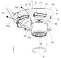
- FIG. 5 is a perspective view of the vicinity of the lower end of the hub 61b.
- 6 is a plan view of the guide portion 70.
- FIG. 7 is a cross-sectional view of the guide portion 70 taken along line VII-VII in FIG.
- the air holes 61f formed in the guide portion 70 pass through the hub 61b in the thickness direction.
- the air hole 61f opens radially outward.
- the air hole 61f has a substantially rectangular shape when viewed from the opening direction.
- the opening direction of the air hole 61f only needs to have a radially outward component, and does not necessarily coincide with the radial direction in a strict sense.
- the air holes 61f open radially outward, the air of the subflow BF flowing downward in the space radially inward of the hub 61b can smoothly flow outward in the radial direction of the hub 61b. can lead to Therefore, the flow path resistance of the subflow BF can be suppressed, the flow rate of the subflow BF can be increased, and the cooling efficiency of the drive unit 50 can be improved.
- the outer peripheral surface 70 a of the guide portion 70 includes a first peripheral surface portion (surrounding surface portion) 72 , a second peripheral surface portion (surrounding surface portion) 73 , a third peripheral surface portion 74 , an overhang surface portion 75 , and a connecting surface portion 76 . It has a front side portion 77 and a rear side portion 78 .
- the first peripheral surface portion 72, the second peripheral surface portion 73, and the third peripheral surface portion 74 are surfaces facing radially outward.
- the first peripheral surface portion 72, the second peripheral surface portion 73, and the third peripheral surface portion 74 each extend in the rotational direction.
- the first peripheral surface portion 72, the second peripheral surface portion 73, and the third peripheral surface portion 74 are curved surfaces that gently curve around the rotation axis R. As shown in FIG.
- the first peripheral surface portion 72 is located on the front side in the rotation direction T with respect to the air hole 61f.
- the second peripheral surface portion 73 is located on the rear side in the rotation direction T with respect to the air hole 61f. That is, the outer peripheral surface 70a of the guide portion 70 has a pair of peripheral surface portions 72 and 73 positioned on the front side and the rear side in the rotation direction T with respect to the air hole 61f.
- the guide portion 70 of the present embodiment has a first peripheral surface portion 72 and a second peripheral surface portion 73 arranged on both sides in the rotation direction (that is, on both sides in the circumferential direction) of the air hole 61f.
- the main flow AF flowing on the one side and the other side of the guide portion 70 in the circumferential direction can be spaced apart from the air hole 61f in the circumferential direction and passed therethrough.
- the air of the sub-flow BF blowing out from the air hole 61f merges with the main flow AF in a sufficiently diffused state.
- the lengths d1 and d2 in the rotational direction of the first peripheral surface portion 72 and the second peripheral surface portion 73 are greater than the length D of the air hole 61f in the rotational direction. Small is preferred. In order to reduce the channel resistance of the subflow BF and increase the flow rate of the subflow BF, it is preferable to increase the length D of the air hole 61f in the rotational direction as much as possible. On the other hand, increasing the rotational direction lengths d1 and d2 of the first peripheral surface portion 72 and the second peripheral surface portion 73 makes it easier to suppress noise when the sub-flow BF and the main flow AF merge.
- the lengths d1 and d2 in the rotational direction of the first peripheral surface portion 72 and the second peripheral surface portion 73 are too large, the circumferential dimension of the guide portion 70 becomes large, and the main flow AF follows the outer peripheral surface of the hub 61b. There is a risk of obstructing the flow.
- the lengths d1 and d2 of the first peripheral surface portion 72 and the second peripheral surface portion 73 in the rotational direction are smaller than the length D of the air hole 61f in the rotational direction, thereby reducing the flow rate of the subflow BF. It is possible to suppress the guide portion 70 from becoming too large while ensuring the size.
- the first peripheral surface portion 72 is a surface formed on the surface of the convex portion 71 that protrudes radially outward with respect to the opening 61fa of the air hole 61f. Therefore, the first peripheral surface portion 72 is arranged radially outside the opening 61fa of the air hole 61f.
- the opening 61fa of the air hole 61f means a region surrounded by the outer edge of the air hole 61f in the penetration direction.
- swirl flow CF a relative air flow
- the first peripheral surface portion 72 located on the front side in the rotation direction T with respect to the air hole 61f is arranged radially outside the opening 61fa of the air hole 61f.
- the direction of the swirling flow CF is changed by the convex portion 71 on the front side in the rotation direction T of the air hole 61f, and flows in the circumferential direction along the first circumferential surface portion 72.
- the first peripheral surface portion 72 is positioned radially outward from the opening 61fa of the air hole 61f, so that the swirling flow CF is spaced radially outward from the opening 61fa of the air hole 61f. can pass.
- the sub-flow BF blowing out from the air hole 61f can be prevented from colliding with the swirl flow CF, and the occurrence of turbulence and the like when the sub-flow BF and swirl flow CF merge can be suppressed, thereby suppressing noise associated with the confluence. can.
- the swirling flow CF away from the air hole 61f the air of the swirling flow CF can be suppressed from flowing into the air hole 61f, and the flow rate of the subflow BF to be blown out from the air hole 61f can be secured.
- the swirl flow CF can be prevented from colliding with the edge of the air hole 61f, and noise generation due to vibration of the edge can be suppressed.
- the second peripheral surface portion 73 is arranged so as to continue to the opening 61fa of the air hole 61f. Therefore, the radial position of the opening 61fa of the air hole 61f and the radial position of the second peripheral surface portion 73 match each other. In addition, the second peripheral surface portion 73 is arranged radially inward with respect to the first peripheral surface portion 72 .
- the second peripheral surface portion 73 on the rear side in the rotational direction T of the air hole 61f does not protrude from the opening 61fa of the air hole 61f. Therefore, the air blown out from the air holes 61f can smoothly flow rearward in the rotation direction T, and the smooth merging of the swirling flow CF and the sub-flow BF can be promoted.
- the third peripheral surface portion 74 is located below the air hole 61f (on one side in the axial direction).
- the third peripheral surface portion 74 is arranged so as to continue to the opening 61fa of the air hole 61f. Therefore, the second peripheral surface portion 73 and the third peripheral surface portion 74 are arranged in a row in the rotation direction.
- the eaves surface portion 75 is located below the air hole 61f (one side in the axial direction). Moreover, the eaves surface portion 75 faces downward (one side in the axial direction).
- the eaves surface portion 75 is a surface extending in the rotational direction.
- the entire rotation direction of the eaves surface portion 75 includes the entire rotation direction of the air hole 61f. That is, the end portion of the eaves surface portion 75 on one side in the circumferential direction is located on the one side in the circumferential direction from the end portion on the one side in the circumferential direction of the air hole 61f, and the end portion on the other side in the circumferential direction of the eaves surface portion 75 is located on the one side in the circumferential direction.
- the eaves surface portion 75 is connected to the first peripheral surface portion 72, the second peripheral surface portion 73, and the third peripheral surface portion 74 via corners.
- a portion of the main flow AF flowing radially outward along the outer peripheral surface of the hub 61b hits the guide portion 70, and flows under the eaves surface portion 75 and radially outwardly of the third peripheral surface portion 74. pass through.
- the third peripheral surface portion 74 is disposed below the air hole 61f (on one side in the axial direction), so that the main flow AF flowing below the eaves surface portion 75 is diverted from the opening of the air hole 61f. 61fa can be passed axially spaced apart. Thereby, collision between the main flow AF and the sub-flow BF at the time of merging can be suppressed, and these can be smoothly merged.
- the main flow AF flowing upward toward the guide portion 70 hits the eaves surface portion 75 positioned below the air hole 61f and directed downward, and changes its flow radially outward.
- the main flow AF can be prevented from flowing into the air hole 61f opening radially outward, and the flow rate of the sub-flow BF can be ensured.
- the main flow AF can be prevented from colliding with the edge of the air hole 61f, and noise generation due to vibration of the edge can be suppressed.
- the front side surface portion 77 faces forward in the rotation direction T. As shown in FIG. 6, the front side surface portion 77 is a surface extending in the radial direction. The front side surface portion 77 is located on the front side in the rotation direction T from the first peripheral surface portion 72 . The front side surface portion 77 receives the swirl flow CF.
- connection surface portion 76 connects the first peripheral surface portion 72 and the front side surface portion 77 .
- the connection surface portion 76 faces the front side in the rotation direction T and is slightly inclined radially outward with respect to the front side in the rotation direction T.
- the connecting surface portion 76 is a surface formed on the surface of the convex portion 71 .
- the connection surface portion 76 is inclined radially inward from the first peripheral surface portion 72 toward the front side surface portion 77 .
- the swirl flow CF hits the front side surface portion 77 and changes its flow radially outward to flow along the first peripheral surface portion 72 .
- the connecting surface portion 76 that connects the first peripheral surface portion 72 and the front side surface portion 77 is formed on the outer peripheral surface of the guide portion 70, the swirling flow CF hitting the front side surface portion 77 is It can be smoothly guided along one peripheral surface portion 72 . As a result, it is possible to suppress the occurrence of turbulence in the swirl flow CF and improve the rotation efficiency of the impeller 60 .
- the connecting surface portion 76 is a concave curved surface.
- the connecting surface portion 76 may be a convex curved surface that smoothly connects the first peripheral surface portion 72 and the front side surface portion 77 with a uniform radius of curvature.
- the connecting surface portion 76 may be a flat tapered surface that linearly connects the first peripheral surface portion 72 and the front side surface portion 77 .
- the rear side portion 78 faces the rear side in the rotation direction T.
- the front side surface portion 77 is a surface extending in the radial direction.
- the rear side surface portion 78 is located on the rear side in the rotation direction T with respect to the second peripheral surface portion 73 .
- the rear side surface portion 78 is connected to the second peripheral surface portion 73 via a corner portion.
- the plurality of guide portions 70 are arranged at intervals in the rotational direction.
- the plurality of blade portions 63 are arranged at intervals in the rotational direction.
- the number of guide portions 70 and the number of blade portions 63 are the same.
- the interval in the rotational direction of the guide portions 70 and the interval in the rotational direction of the blade portions 63 may be the same or different.
- the guide portions 70 and the blade portions 63 are provided in the same number, and the guide portions 70 and the blade portions 63 are spaced apart from each other. Variation can be suppressed and the rotation efficiency of the impeller 60 can be improved.
- the guide portions 70 and the blade portions 63 are provided in the same number, and the guide portions 70 and the blade portions 63 are spaced apart from each other. Variation in the flow velocity of the air that is blown out and sent radially outward by the vanes 63 can be suppressed. Therefore, it is possible to suppress variations in air resistance in the rotation direction of the impeller 60, and to increase the rotational efficiency of the impeller 60.
- the main plate of the impeller, the shroud, and the plurality of blades are separate members and fixed to each other.
- the main plate, shroud and plurality of vanes may be parts of a single member.
- the main plate, the shroud, and the blade portion may each have a mode formed by combining a plurality of members.
- the centrifugal fan according to the embodiment can also be used in other types of indoor units, and can also be widely used in various types of equipment equipped with air blowing means other than air conditioners.
- the heat exchangers shown in the above-described embodiments are merely examples of pressure loss bodies placed in air flow paths generated by centrifugal fans in air conditioners. Therefore, for example, an air purifying filter can be mentioned as a pressure loss body placed in the flow path of air generated by a centrifugal blower in an air purifying device. That is, the centrifugal blower described in the above embodiments can also be employed as a blower in an air cleaner.
Landscapes
- Engineering & Computer Science (AREA)
- Mechanical Engineering (AREA)
- General Engineering & Computer Science (AREA)
- Physics & Mathematics (AREA)
- Thermal Sciences (AREA)
- Chemical & Material Sciences (AREA)
- Combustion & Propulsion (AREA)
- Structures Of Non-Positive Displacement Pumps (AREA)
Priority Applications (7)
| Application Number | Priority Date | Filing Date | Title |
|---|---|---|---|
| CN202280082202.8A CN118475776A (zh) | 2022-01-17 | 2022-01-17 | 离心送风机以及室内机 |
| AU2022432675A AU2022432675B2 (en) | 2022-01-17 | 2022-01-17 | Centrifugal blower, and indoor unit |
| US18/703,586 US20240418377A1 (en) | 2022-01-17 | 2022-01-17 | Centrifugal blower, and indoor unit |
| GB2406493.3A GB2627101B (en) | 2022-01-17 | 2022-01-17 | Centrifugal blower, and indoor unit |
| DE112022006421.8T DE112022006421T5 (de) | 2022-01-17 | 2022-01-17 | Zentrifugalgebläse und Inneneinheit |
| PCT/JP2022/001286 WO2023135782A1 (ja) | 2022-01-17 | 2022-01-17 | 遠心送風機、および室内機 |
| JP2023573783A JP7693023B2 (ja) | 2022-01-17 | 2022-01-17 | 遠心送風機、および室内機 |
Applications Claiming Priority (1)
| Application Number | Priority Date | Filing Date | Title |
|---|---|---|---|
| PCT/JP2022/001286 WO2023135782A1 (ja) | 2022-01-17 | 2022-01-17 | 遠心送風機、および室内機 |
Publications (1)
| Publication Number | Publication Date |
|---|---|
| WO2023135782A1 true WO2023135782A1 (ja) | 2023-07-20 |
Family
ID=87278748
Family Applications (1)
| Application Number | Title | Priority Date | Filing Date |
|---|---|---|---|
| PCT/JP2022/001286 Ceased WO2023135782A1 (ja) | 2022-01-17 | 2022-01-17 | 遠心送風機、および室内機 |
Country Status (7)
| Country | Link |
|---|---|
| US (1) | US20240418377A1 (https=) |
| JP (1) | JP7693023B2 (https=) |
| CN (1) | CN118475776A (https=) |
| AU (1) | AU2022432675B2 (https=) |
| DE (1) | DE112022006421T5 (https=) |
| GB (1) | GB2627101B (https=) |
| WO (1) | WO2023135782A1 (https=) |
Families Citing this family (1)
| Publication number | Priority date | Publication date | Assignee | Title |
|---|---|---|---|---|
| RU2484071C2 (ru) * | 2011-05-27 | 2013-06-10 | Государственное образовательное учреждение высшего профессионального образования "Российский государственный педагогический университет им. А.И. Герцена" | Способ фиксации суспензии на керамике |
Citations (8)
| Publication number | Priority date | Publication date | Assignee | Title |
|---|---|---|---|---|
| JPH074390A (ja) * | 1993-06-15 | 1995-01-10 | Matsushita Refrig Co Ltd | 遠心送風機 |
| JPH11270493A (ja) * | 1998-03-24 | 1999-10-05 | Daikin Ind Ltd | 遠心ファン |
| JP2000205195A (ja) * | 1999-01-11 | 2000-07-25 | Mitsubishi Electric Corp | 遠心送風機の羽根車および空気調和機 |
| JP2003097488A (ja) * | 2001-09-27 | 2003-04-03 | Hitachi Ltd | 遠心送風機及び空気調和機 |
| JP2006029319A (ja) * | 2004-06-15 | 2006-02-02 | Matsushita Electric Ind Co Ltd | ターボファン及びターボファンの製造方法 |
| JP2009221928A (ja) * | 2008-03-14 | 2009-10-01 | Calsonic Kansei Corp | シロッコファン及びその製造方法 |
| JP2016223334A (ja) * | 2015-05-28 | 2016-12-28 | ダイキン工業株式会社 | 送風機 |
| JP2019163721A (ja) * | 2018-03-20 | 2019-09-26 | ミネベアミツミ株式会社 | 送風機 |
Family Cites Families (9)
| Publication number | Priority date | Publication date | Assignee | Title |
|---|---|---|---|---|
| JPS60164699U (ja) * | 1984-04-09 | 1985-11-01 | 日産自動車株式会社 | 遠心送風機 |
| JPH11101194A (ja) * | 1997-09-30 | 1999-04-13 | Daikin Ind Ltd | 遠心送風機及び該遠心送風機を備えた空気調和機 |
| JP2000227231A (ja) * | 1999-02-05 | 2000-08-15 | Fujitsu General Ltd | 天井埋込型空気調和機 |
| AU2003284610B2 (en) * | 2002-12-16 | 2006-11-16 | Daikin Industries, Ltd. | Centrifugal fan, and air conditioner provided therewith |
| JP4639911B2 (ja) * | 2005-03-31 | 2011-02-23 | ダイキン工業株式会社 | 空気調和機 |
| JP6211101B2 (ja) * | 2014-01-10 | 2017-10-11 | 三菱電機株式会社 | 遠心ファン、空気調和装置及び空気清浄装置 |
| EP3093499B1 (en) * | 2014-01-10 | 2020-06-03 | Mitsubishi Electric Corporation | Fan, centrifugal fan, and air conditioning device |
| KR20220033358A (ko) * | 2020-09-09 | 2022-03-16 | 삼성전자주식회사 | 팬, 팬을 갖는 공기조화기 및 팬의 제조방법 |
| WO2022055112A1 (ko) * | 2020-09-09 | 2022-03-17 | 삼성전자주식회사 | 팬, 팬을 갖는 공기조화기 및 팬의 제조방법 |
-
2022
- 2022-01-17 WO PCT/JP2022/001286 patent/WO2023135782A1/ja not_active Ceased
- 2022-01-17 US US18/703,586 patent/US20240418377A1/en active Pending
- 2022-01-17 DE DE112022006421.8T patent/DE112022006421T5/de active Pending
- 2022-01-17 CN CN202280082202.8A patent/CN118475776A/zh active Pending
- 2022-01-17 GB GB2406493.3A patent/GB2627101B/en active Active
- 2022-01-17 AU AU2022432675A patent/AU2022432675B2/en active Active
- 2022-01-17 JP JP2023573783A patent/JP7693023B2/ja active Active
Patent Citations (8)
| Publication number | Priority date | Publication date | Assignee | Title |
|---|---|---|---|---|
| JPH074390A (ja) * | 1993-06-15 | 1995-01-10 | Matsushita Refrig Co Ltd | 遠心送風機 |
| JPH11270493A (ja) * | 1998-03-24 | 1999-10-05 | Daikin Ind Ltd | 遠心ファン |
| JP2000205195A (ja) * | 1999-01-11 | 2000-07-25 | Mitsubishi Electric Corp | 遠心送風機の羽根車および空気調和機 |
| JP2003097488A (ja) * | 2001-09-27 | 2003-04-03 | Hitachi Ltd | 遠心送風機及び空気調和機 |
| JP2006029319A (ja) * | 2004-06-15 | 2006-02-02 | Matsushita Electric Ind Co Ltd | ターボファン及びターボファンの製造方法 |
| JP2009221928A (ja) * | 2008-03-14 | 2009-10-01 | Calsonic Kansei Corp | シロッコファン及びその製造方法 |
| JP2016223334A (ja) * | 2015-05-28 | 2016-12-28 | ダイキン工業株式会社 | 送風機 |
| JP2019163721A (ja) * | 2018-03-20 | 2019-09-26 | ミネベアミツミ株式会社 | 送風機 |
Also Published As
| Publication number | Publication date |
|---|---|
| JPWO2023135782A1 (https=) | 2023-07-20 |
| GB2627101B (en) | 2026-01-21 |
| AU2022432675B2 (en) | 2025-06-26 |
| DE112022006421T5 (de) | 2024-12-19 |
| JP7693023B2 (ja) | 2025-06-16 |
| US20240418377A1 (en) | 2024-12-19 |
| GB202406493D0 (en) | 2024-06-26 |
| CN118475776A (zh) | 2024-08-09 |
| GB2627101A (en) | 2024-08-14 |
| AU2022432675A1 (en) | 2024-05-09 |
Similar Documents
| Publication | Publication Date | Title |
|---|---|---|
| JP6377172B2 (ja) | プロペラファン、プロペラファン装置および空気調和装置用室外機 | |
| JP2008144753A (ja) | ターボファン及びこれを備えた空気調和機 | |
| WO2020008519A1 (ja) | 多翼送風機及び空気調和装置 | |
| EP4400777A1 (en) | Ceiling-embedded air conditioner | |
| WO2023135782A1 (ja) | 遠心送風機、および室内機 | |
| JP2004353510A (ja) | 遠心送風機及び遠心送風機を備えた空気調和装置 | |
| JP7258136B2 (ja) | 軸流ファン、送風装置、及び、冷凍サイクル装置 | |
| JP2012002165A (ja) | ターボファンおよびそれを用いた空気調和機 | |
| JP6925571B1 (ja) | 送風機、室内機および空気調和装置 | |
| WO2019163450A1 (ja) | ターボファン、及び空気調和機の室内機 | |
| US20250129788A1 (en) | Cross flow fan and blowing device | |
| JP7558434B2 (ja) | 室内機、および空気調和機 | |
| JP2018150910A (ja) | 両吸込型遠心ファン | |
| JP2018119692A (ja) | 空気調和機の室内機 | |
| AU2016427676B2 (en) | Propeller fan, outdoor unit, and refrigeration cycle apparatus | |
| JP6625213B2 (ja) | 多翼ファン及び空気調和機 | |
| CN116507809A (zh) | 轴流风扇、送风装置以及制冷循环装置 | |
| WO2023223383A1 (ja) | クロスフローファン、送風装置及び冷凍サイクル装置 | |
| WO2024214236A1 (ja) | 空気調和機の室内機、および、それを備えた空気調和機 | |
| WO2023152802A1 (ja) | 室内機及びこれを備えた空気調和装置 | |
| WO2023135775A1 (ja) | 羽根車、遠心送風機、および室内機 | |
| JP2000065379A (ja) | 遠心式送風手段を用いた熱交換器 | |
| TW202421971A (zh) | 室內機及空氣調和機 | |
| WO2024189889A1 (ja) | 空気調和機の室内機、および、それを備えた空気調和機 | |
| WO2025017869A1 (ja) | 送風機、空気調和装置及び冷凍サイクル装置 |
Legal Events
| Date | Code | Title | Description |
|---|---|---|---|
| 121 | Ep: the epo has been informed by wipo that ep was designated in this application |
Ref document number: 22920307 Country of ref document: EP Kind code of ref document: A1 |
|
| WWE | Wipo information: entry into national phase |
Ref document number: 2023573783 Country of ref document: JP |
|
| WWE | Wipo information: entry into national phase |
Ref document number: 18703586 Country of ref document: US Ref document number: AU2022432675 Country of ref document: AU |
|
| ENP | Entry into the national phase |
Ref document number: 202406493 Country of ref document: GB Kind code of ref document: A Free format text: PCT FILING DATE = 20220117 Ref document number: 2022432675 Country of ref document: AU Date of ref document: 20220117 Kind code of ref document: A |
|
| WWE | Wipo information: entry into national phase |
Ref document number: 2406493.3 Country of ref document: GB |
|
| WWE | Wipo information: entry into national phase |
Ref document number: 202280082202.8 Country of ref document: CN |
|
| WWE | Wipo information: entry into national phase |
Ref document number: 202427045685 Country of ref document: IN |
|
| WWP | Wipo information: published in national office |
Ref document number: 2406493.3 Country of ref document: GB |
|
| WWE | Wipo information: entry into national phase |
Ref document number: 112022006421 Country of ref document: DE |
|
| 122 | Ep: pct application non-entry in european phase |
Ref document number: 22920307 Country of ref document: EP Kind code of ref document: A1 |