WO2023135775A1 - 羽根車、遠心送風機、および室内機 - Google Patents
羽根車、遠心送風機、および室内機 Download PDFInfo
- Publication number
- WO2023135775A1 WO2023135775A1 PCT/JP2022/001269 JP2022001269W WO2023135775A1 WO 2023135775 A1 WO2023135775 A1 WO 2023135775A1 JP 2022001269 W JP2022001269 W JP 2022001269W WO 2023135775 A1 WO2023135775 A1 WO 2023135775A1
- Authority
- WO
- WIPO (PCT)
- Prior art keywords
- impeller
- housing
- shroud
- extending direction
- accommodating
- Prior art date
- Legal status (The legal status is an assumption and is not a legal conclusion. Google has not performed a legal analysis and makes no representation as to the accuracy of the status listed.)
- Ceased
Links
Images








Classifications
-
- F—MECHANICAL ENGINEERING; LIGHTING; HEATING; WEAPONS; BLASTING
- F24—HEATING; RANGES; VENTILATING
- F24F—AIR-CONDITIONING; AIR-HUMIDIFICATION; VENTILATION; USE OF AIR CURRENTS FOR SCREENING
- F24F1/00—Room units for air-conditioning, e.g. separate or self-contained units or units receiving primary air from a central station
- F24F1/0007—Indoor units, e.g. fan coil units
- F24F1/0018—Indoor units, e.g. fan coil units characterised by fans
- F24F1/0022—Centrifugal or radial fans
-
- F—MECHANICAL ENGINEERING; LIGHTING; HEATING; WEAPONS; BLASTING
- F04—POSITIVE - DISPLACEMENT MACHINES FOR LIQUIDS; PUMPS FOR LIQUIDS OR ELASTIC FLUIDS
- F04D—NON-POSITIVE-DISPLACEMENT PUMPS
- F04D29/00—Details, component parts, or accessories
- F04D29/26—Rotors specially for elastic fluids
- F04D29/28—Rotors specially for elastic fluids for centrifugal or helico-centrifugal pumps for radial-flow or helico-centrifugal pumps
-
- F—MECHANICAL ENGINEERING; LIGHTING; HEATING; WEAPONS; BLASTING
- F01—MACHINES OR ENGINES IN GENERAL; ENGINE PLANTS IN GENERAL; STEAM ENGINES
- F01D—NON-POSITIVE DISPLACEMENT MACHINES OR ENGINES, e.g. STEAM TURBINES
- F01D5/00—Blades; Blade-carrying members; Heating, heat-insulating, cooling or antivibration means on the blades or the members
- F01D5/12—Blades
- F01D5/22—Blade-to-blade connections, e.g. for damping vibrations
- F01D5/225—Blade-to-blade connections, e.g. for damping vibrations by shrouding
-
- F—MECHANICAL ENGINEERING; LIGHTING; HEATING; WEAPONS; BLASTING
- F04—POSITIVE - DISPLACEMENT MACHINES FOR LIQUIDS; PUMPS FOR LIQUIDS OR ELASTIC FLUIDS
- F04D—NON-POSITIVE-DISPLACEMENT PUMPS
- F04D17/00—Radial-flow pumps, e.g. centrifugal pumps; Helico-centrifugal pumps
- F04D17/08—Centrifugal pumps
-
- F—MECHANICAL ENGINEERING; LIGHTING; HEATING; WEAPONS; BLASTING
- F04—POSITIVE - DISPLACEMENT MACHINES FOR LIQUIDS; PUMPS FOR LIQUIDS OR ELASTIC FLUIDS
- F04D—NON-POSITIVE-DISPLACEMENT PUMPS
- F04D29/00—Details, component parts, or accessories
- F04D29/26—Rotors specially for elastic fluids
- F04D29/28—Rotors specially for elastic fluids for centrifugal or helico-centrifugal pumps for radial-flow or helico-centrifugal pumps
- F04D29/281—Rotors specially for elastic fluids for centrifugal or helico-centrifugal pumps for radial-flow or helico-centrifugal pumps for fans or blowers
-
- F—MECHANICAL ENGINEERING; LIGHTING; HEATING; WEAPONS; BLASTING
- F04—POSITIVE - DISPLACEMENT MACHINES FOR LIQUIDS; PUMPS FOR LIQUIDS OR ELASTIC FLUIDS
- F04D—NON-POSITIVE-DISPLACEMENT PUMPS
- F04D29/00—Details, component parts, or accessories
- F04D29/26—Rotors specially for elastic fluids
- F04D29/28—Rotors specially for elastic fluids for centrifugal or helico-centrifugal pumps for radial-flow or helico-centrifugal pumps
- F04D29/30—Vanes
-
- F—MECHANICAL ENGINEERING; LIGHTING; HEATING; WEAPONS; BLASTING
- F04—POSITIVE - DISPLACEMENT MACHINES FOR LIQUIDS; PUMPS FOR LIQUIDS OR ELASTIC FLUIDS
- F04D—NON-POSITIVE-DISPLACEMENT PUMPS
- F04D29/00—Details, component parts, or accessories
- F04D29/58—Cooling; Heating; Diminishing heat transfer
- F04D29/582—Cooling; Heating; Diminishing heat transfer specially adapted for elastic fluid pumps
-
- F—MECHANICAL ENGINEERING; LIGHTING; HEATING; WEAPONS; BLASTING
- F04—POSITIVE - DISPLACEMENT MACHINES FOR LIQUIDS; PUMPS FOR LIQUIDS OR ELASTIC FLUIDS
- F04D—NON-POSITIVE-DISPLACEMENT PUMPS
- F04D29/00—Details, component parts, or accessories
- F04D29/60—Mounting; Assembling; Disassembling
- F04D29/62—Mounting; Assembling; Disassembling of radial or helico-centrifugal pumps
- F04D29/624—Mounting; Assembling; Disassembling of radial or helico-centrifugal pumps especially adapted for elastic fluid pumps
- F04D29/626—Mounting or removal of fans
-
- F—MECHANICAL ENGINEERING; LIGHTING; HEATING; WEAPONS; BLASTING
- F24—HEATING; RANGES; VENTILATING
- F24F—AIR-CONDITIONING; AIR-HUMIDIFICATION; VENTILATION; USE OF AIR CURRENTS FOR SCREENING
- F24F1/00—Room units for air-conditioning, e.g. separate or self-contained units or units receiving primary air from a central station
- F24F1/0007—Indoor units, e.g. fan coil units
- F24F1/0043—Indoor units, e.g. fan coil units characterised by mounting arrangements
- F24F1/0047—Indoor units, e.g. fan coil units characterised by mounting arrangements mounted in the ceiling or at the ceiling
Definitions
- the present disclosure relates to impellers, centrifugal fans, and indoor units.
- Patent Literature 1 describes an impeller provided with a side plate having a fitting recess into which an end of a hollow blade is fitted.
- the part of the hollow blade other than the part that contacts the inner surface of the fitting recess is provided.
- a gap is provided between the portion and the side plate. Air flows from the positive pressure side of the hollow blades to the negative pressure side of the hollow blades through the gaps, and there is a problem that the air blowing efficiency of the impeller is lowered.
- the present disclosure provides an impeller having a structure that can suppress a decrease in air blowing efficiency, a centrifugal fan including such an impeller, and an indoor unit including such a centrifugal fan. is one of the purposes.
- One aspect of the impeller according to the present disclosure is an impeller that is rotatable around a rotation shaft, and includes a base portion and a shroud portion positioned on the first side in the axial direction of the rotation shaft with respect to the base portion. and a plurality of blade portions positioned between the base portion and the shroud portion in the axial direction and spaced apart in the rotational direction of the impeller, wherein the shroud portion includes a shroud body portion.
- each of the plurality of blade portions has a blade main body portion and a projecting portion projecting from the blade main body portion to the first side, and one end portion of the blade main body portion in the extending direction in which the blade main body portion extends when viewed in the axial direction is positioned radially inward about the rotating shaft from the other end of the blade main body in the extending direction, and the projecting portions of the plurality of blade portions are located in the plurality of projecting housing portions, respectively.
- Each of the plurality of protruding accommodating portions accommodated has a first accommodating portion and a second accommodating portion connected to an end portion of the first accommodating portion in the extending direction, and the protruding portion a first convex portion accommodated in one accommodation portion and fixed to the shroud portion; a second convex portion connected to an end portion of the first convex portion in the extending direction and accommodated in the second accommodation portion; wherein the first convex portion is fixed in contact with a surface located on the first side of the inner surface of the first accommodating portion, and the second convex portion is located on the inner surface of the second accommodating portion. Among them, it faces the surface located on the first side with a gap therebetween.
- centrifugal fan includes the impeller described above, and a drive section that rotates the impeller around the rotation axis.
- One aspect of the indoor unit according to the present disclosure is an indoor unit of an air conditioner, comprising the centrifugal fan described above and a heat exchanger to which air is sent by the centrifugal fan.
- FIG. 1 is a schematic diagram showing a schematic configuration of an air conditioner according to Embodiment 1.
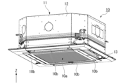
- FIG. Fig. 2 is a perspective view showing the indoor unit according to Embodiment 1;
- Fig. 2 is a cross-sectional view showing the indoor unit according to Embodiment 1;
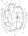
- 1 is a perspective view showing an impeller in Embodiment 1.
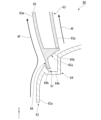
- FIG. 6 is a cross-sectional view showing the protrusion accommodating portion and the protrusion in Embodiment 1, and is a cross-sectional view taken along the line VI-VI in FIG. 5;
- FIG. 4 is a perspective view showing a protruding accommodating portion according to Embodiment 1;
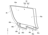
- FIG. 4 is a perspective view showing a blade portion according to Embodiment 1;
- FIG. FIG. 8 is a perspective view showing part of an impeller according to Embodiment 2; It is the figure which looked at a part of impeller in Embodiment 2 from the lower side.
- FIG. 11 is a perspective view showing part of an impeller according to Embodiment 3;
- FIG. 11 is a cross-sectional view showing part of an impeller in Embodiment 3;
- FIG. 11 is a perspective view showing a part of a blade part according to Embodiment 3;
- FIG. 11 is a perspective view showing a part of an impeller according to Embodiment 4; It is a sectional view showing a part of impeller of a comparative example.
- FIG. 18 is a cross-sectional view showing part of the impeller of the comparative example, taken along line XVIII-XVIII in FIG. 17;
- the Z-axis is shown as appropriate.
- the Z-axis indicates the vertical direction.
- the side of the vertical direction Z to which the Z-axis arrow points (+Z side) is the upper side
- the opposite side of the vertical direction Z to which the Z-axis arrow points (-Z side) is the lower side.
- the vertical direction Z corresponds to the axial direction of the rotation axis R described later.
- the lower side corresponds to the "first side” in the axial direction of the rotating shaft R
- the upper side corresponds to the "second side” opposite to the first side in the axial direction of the rotating shaft R.
- FIG. 1 is a schematic diagram showing a schematic configuration of an air conditioner 100 according to Embodiment 1.
- the air conditioner 100 includes an indoor unit 10 , an outdoor unit 20 and a circulation path section 30 .
- the indoor unit 10 is arranged indoors.
- the outdoor unit 20 is arranged outdoors.
- the indoor unit 10 and the outdoor unit 20 are connected to each other by a circulation path section 30 through which a refrigerant 33 circulates.
- the indoor unit 10 and the outdoor unit 20 are heat exchange units that exchange heat with air.
- the air conditioner 100 can adjust the temperature of the indoor air by exchanging heat between the refrigerant 33 flowing in the circulation path section 30 and the indoor air in which the indoor unit 10 is arranged.
- the refrigerant 33 for example, a fluorine-based refrigerant having a low global warming potential (GWP), a hydrocarbon-based refrigerant, or the like can be used.
- GWP global warming potential
- hydrocarbon-based refrigerant or the like
- the outdoor unit 20 has a compressor 21 , a heat exchanger 23 , a flow control valve 24 , a blower 25 and a four-way valve 22 .
- Compressor 21 , heat exchanger 23 , flow control valve 24 and four-way valve 22 are connected by circulation path section 30 .
- the four-way valve 22 is provided in a portion of the circulation path section 30 that is connected to the discharge side of the compressor 21 .
- the four-way valve 22 can reverse the direction of the refrigerant 33 flowing through the circulation path section 30 by switching a part of the path of the circulation path section 30 .
- the path connected by the four-way valve 22 is the path indicated by the solid line in the four-way valve 22 in FIG. 1
- the refrigerant 33 flows in the circulation path section 30 in the direction indicated by the solid arrow in FIG.
- the path connected by the four-way valve 22 is the path indicated by the dashed line in the four-way valve 22 in FIG. 1
- the refrigerant 33 flows in the circulation path section 30 in the direction indicated by the dashed arrow in FIG.
- the indoor unit 10 includes a housing 11, a heat exchanger 14, and a centrifugal fan 40.
- the indoor unit 10 is capable of a cooling operation for cooling the air in the room in which the indoor unit 10 is arranged and a heating operation for warming the air in the room in which the indoor unit 10 is arranged.
- the refrigerant 33 flowing through the circulation path portion 30 flows in the direction indicated by the solid arrow in FIG.
- the refrigerant 33 flowing through the circulation path portion 30 flows through the compressor 21, the heat exchanger 23 of the outdoor unit 20, the flow control valve 24, and the heat exchanger 14 of the indoor unit 10. in this order to return to the compressor 21 .
- the heat exchanger 23 inside the outdoor unit 20 functions as a condenser
- the heat exchanger 14 inside the indoor unit 10 functions as an evaporator.
- the refrigerant 33 flowing through the circulation path portion 30 flows in the direction indicated by the dashed line in FIG.
- the refrigerant 33 flowing through the circulation path portion 30 flows through the compressor 21, the heat exchanger 14 of the indoor unit 10, the flow control valve 24, and the heat exchanger 23 of the outdoor unit 20. in this order to return to the compressor 21 .
- the heat exchanger 23 inside the outdoor unit 20 functions as an evaporator
- the heat exchanger 14 inside the indoor unit 10 functions as a condenser.
- FIG. 2 is a perspective view showing the indoor unit 10.
- FIG. FIG. 3 is a cross-sectional view showing the indoor unit 10.
- the indoor unit 10 in Embodiment 1 is a ceiling-embedded indoor unit that is embedded in the ceiling.
- the housing 11 accommodates the heat exchanger 14 and the centrifugal blower 40 inside.
- the housing 11 has a housing main body 12 that accommodates the heat exchanger 14 and the centrifugal blower 40 therein, and a decorative panel 13 attached below the housing main body 12 .
- the housing main body 12 is embedded in the ceiling in the room where the indoor unit 10 is installed.
- the decorative panel 13 is exposed in the room where the indoor unit 10 is installed.
- the heat exchanger 14 is housed inside the housing main body 12 . Air is sent to the heat exchanger 14 by a centrifugal blower 40 .
- the heat exchanger 14 has a frame shape surrounding the centrifugal blower 40 .
- the heat exchanger 14 is arranged to face an exhaust port 60b, which will be described later.
- the indoor unit 10 has an inlet 10a and an outlet 10b.
- the suction port 10a and the blowout port 10b are opened on the lower surface of the decorative panel 13.
- the suction port 10a is positioned in the center of the indoor unit 10 when viewed in the vertical direction Z.
- a plurality of outlets 10b are provided.
- a plurality of outlets 10b are arranged to surround the inlet 10a when viewed in the vertical direction Z.
- four outlets 10b are provided.
- the centrifugal blower 40 is a blower that sends air to the heat exchanger 14. Air flows inside the indoor unit 10 by driving the centrifugal blower 40 .
- arrows AF indicate the air flow generated by driving the centrifugal blower 40 .
- FIG. 3 when the centrifugal blower 40 is driven, air is sucked into the interior of the indoor unit 10 through the suction port 10a. Indoor air sucked into the interior of the indoor unit 10 through the suction port 10a passes through the heat exchanger 14 and is blown out into the room through four outlets 10b.
- the centrifugal blower 40 is fixed to the lower surface of the top plate portion 12a of the housing main body portion 12.
- the centrifugal blower 40 includes a drive section 50 and an impeller 60 .
- the drive unit 50 rotates the impeller 60 around the rotation axis R.
- a rotation axis R shown as appropriate in the drawings is a virtual axis extending in the vertical direction Z. As shown in FIG. That is, the axial direction of the rotation axis R is the vertical direction Z. As shown in FIG.
- the rotation axis R passes through the center of the indoor unit 10 when viewed in the vertical direction Z.
- the radial direction around the rotation axis R is simply referred to as the "radial direction”, and the circumferential direction around the rotation axis R is referred to as the "rotational direction”.
- the direction of rotation is appropriately indicated by an arrow ⁇ in the drawings.
- the impeller 60 rotates in the direction indicated by the arrow ⁇ .
- the side toward which the arrow ⁇ points in the direction of rotation (+ ⁇ side) is the "front side”
- the side opposite to the side toward which the arrow ⁇ points in the direction of rotation ( ⁇ side) is the "rear side”.
- the forward side (+ ⁇ side) in the rotational direction is the side that advances counterclockwise about the rotation axis R when viewed from below.
- the rear side ( ⁇ side) in the rotational direction is the side proceeding clockwise about the rotation axis R when viewed from below.
- the drive unit 50 in Embodiment 1 is a motor.
- the driving portion 50 has a driving portion main body 51 fixed to the lower surface of the top plate portion 12 a and a rotating shaft 52 projecting downward from the driving portion main body 51 from the inside of the driving portion main body 51 .
- Rotating shaft 52 is part of the rotor in drive section 50 .
- the rotating shaft 52 is rotatable around the rotation axis R.
- the drive unit 50 may have any configuration as long as it can rotate the impeller 60 around the rotation axis R.
- the impeller 60 is rotatable around the rotation axis R.
- the impeller 60 is made of resin, for example.
- the impeller 60 is fixed to a portion of the rotating shaft 52 of the drive section 50 that protrudes downward from the drive section main body 51 via a connecting member 53 .
- the connecting member 53 is a cylindrical member centered on the rotation axis R. As shown in FIG.
- the connecting member 53 is fixed to the outer peripheral surface of the rotating shaft 52 .
- FIG. 4 is a perspective view showing the impeller 60.
- FIG. FIG. 5 is a view of the impeller 60 viewed from below.
- the impeller 60 includes a base portion 61 , a shroud portion 62 and a plurality of blade portions 63 .
- the base 61 is fixed to the rotating shaft 52 via the connecting member 53 .
- the base portion 61 has an annular plate portion 61a, a bulging portion 61b, and a plurality of guide portions 61f.
- the annular plate portion 61a has an annular plate shape centered on the rotation axis R.
- the bulging portion 61b protrudes downward from the radial inner edge portion of the annular plate portion 61a.
- the bulging portion 61b has a cylindrical shape centered on the rotation axis R.
- the driving portion main body 51 is positioned inside the bulging portion 61b.
- the bulging portion 61b has a peripheral wall portion 61c, a bottom plate portion 61d, and a cylindrical portion 61e.
- the peripheral wall portion 61c is open upward and has a cylindrical shape centered on the rotation axis R.
- the inner diameter of the peripheral wall portion 61c and the outer diameter of the peripheral wall portion 61c decrease downward.
- the bottom plate portion 61d is connected to the lower end portion of the peripheral wall portion 61c.
- the bottom plate portion 61d has an annular plate shape centering on the rotation axis R.
- the tubular portion 61e protrudes downward from the radial inner edge portion of the bottom plate portion 61d.
- the cylindrical portion 61e has a cylindrical shape with the rotation axis R as the center and is open downward.
- a connecting member 53 is fixed to the inner peripheral surface of the cylindrical portion 61e.
- the tubular portion 61 e is fixed to the rotating shaft 52 via a connecting member 53 .
- a plurality of guide portions 61f are formed on the lower surface of the annular plate portion 61a.
- the plurality of guide portions 61f When viewed in the vertical direction Z, the plurality of guide portions 61f extend obliquely in the rotational direction with respect to the radial direction, and have an elongated, substantially U-shape that opens outward in the radial direction.
- the plurality of guide portions 61f are located on the front side (+ ⁇ side) in the rotational direction as they extend radially inward.
- the plurality of guide portions 61f are arranged at intervals over one circumference in the rotation direction. In Embodiment 1, seven guide portions 61f are provided. The intervals between the plurality of guide portions 61f may be equal intervals or may be different from each other.
- the shroud portion 62 is located below the annular plate portion 61a of the base portion 61 and is spaced apart therefrom. That is, the shroud portion 62 is positioned on the lower side (first side) of the base portion 61 in the axial direction of the rotation axis R. As shown in FIG.
- the shroud portion 62 has an annular shape centered on the rotation axis R. As shown in FIG.
- the radially inner edge of the shroud portion 62 is located radially outside the bulging portion 61b.
- the shroud portion 62 has a cylindrical shape centered on the rotation axis R and opened on both sides in the vertical direction Z. As shown in FIG.
- the inner diameter of the shroud portion 62 and the outer diameter of the shroud portion 62 decrease downward.
- the shroud portion 62 has a shroud main body portion 62a and a plurality of projecting accommodation portions 64 .
- the shroud main body 62a has a cylindrical shape centered on the rotation axis R and opening on both sides in the vertical direction Z.
- the inner diameter of the shroud body portion 62a and the outer diameter of the shroud body portion 62a decrease downward.
- the shroud main body 62a in a cross section perpendicular to the rotation direction, has an arcuate shape that protrudes radially inward and obliquely upward.
- the radial inner edge of the shroud main body 62a is the lower end of the shroud main body 62a.
- a radially inner edge portion of the shroud body portion 62a is an intake port 60a that opens downward.
- the intake port 60a is arranged above and apart from the intake port 10a of the indoor unit 10 .
- the radial outer edge of the shroud main body 62a is the upper end of the shroud main body 62a.
- the space between the radial outer edge of the shroud main body 62a and the radial outer edge of the annular plate portion 61a in the vertical direction Z is partitioned in the rotational direction by the plurality of vanes 63.
- a plurality of exhaust ports 60b opening radially outward are formed.
- the plurality of exhaust ports 60b are spaced apart from each other over one circumference in the rotational direction. In Embodiment 1, seven exhaust ports 60b are provided.
- the heat exchangers 14 are disposed facing each other on the radially outer side of each exhaust port 60b. The intervals between the plurality of exhaust ports 60b may be equal or may be different from each other.
- the impeller 60 When the impeller 60 is rotated around the rotation axis R by the drive unit 50, the air sucked into the indoor unit 10 through the suction port 10a flows into the impeller 60 through the intake port 60a.
- the air that has flowed into the impeller 60 is discharged radially outward from the plurality of exhaust ports 60b.
- the air discharged from the plurality of air outlets 60b passes through the heat exchanger 14 and is blown into the room from the plurality of air outlets 10b.
- FIG. 6 is a cross-sectional view showing the protruding accommodating portion 64 and a protruding portion 66 described later, and is a cross-sectional view taken along the line VI-VI in FIG.
- FIG. 7 is a perspective view showing the protruding accommodating portion 64.
- the plurality of projecting accommodating portions 64 project downward from the shroud body portion 62a.
- the plurality of projecting accommodation portions 64 are hollow.
- the plurality of projecting accommodating portions 64 are open upward.
- each of the plurality of projecting housing portions 64 extends obliquely in the rotational direction with respect to the radial direction when viewed in the vertical direction Z. As shown in FIG.
- each protruding housing portion 64 is positioned forward in the rotational direction (+ ⁇ side) of the radially outer end of each protruding housing portion 64 .
- Each protruding accommodation portion 64 obliquely extends linearly toward the front side in the rotational direction as it extends radially inward when viewed in the vertical direction Z. As shown in FIG.
- the direction in which each projecting accommodation portion 64 extends when viewed in the vertical direction Z is the extension direction in which the blade body portion 65 described later extends when viewed in the vertical direction Z.
- the direction in which the later-described blade main body 65 extends when viewed in the vertical direction Z is called the "stretching direction".
- the radially inner side in the drawing direction is called the drawing direction inner side
- the radially outer side in the drawing direction is called the drawing direction outer side.
- the inner side in the extending direction is the radially inner side and the front side (+ ⁇ side) in the rotational direction.
- the outside in the stretching direction is the outside in the radial direction and the rear side ( ⁇ side) in the rotation direction.
- the left side in FIG. 6 is the inner side in the drawing direction
- the right side in FIG. 6 is the outer side in the drawing direction.
- each of the plurality of protruding housing portions 64 has a first housing portion 64a.
- the first accommodating portion 64a has a substantially rectangular parallelepiped box shape extending in the direction in which the projecting accommodating portion 64 extends.
- the first housing portion 64a has an outer portion 64c and an inner portion 64d.
- the outer portion 64c is a portion of the first accommodating portion 64a on the outer side in the extending direction.
- the inner portion 64d is the inner portion in the extending direction of the first accommodation portion 64a.
- the extension-direction outer end of the outer portion 64c is the extension-direction outer end of the first accommodating portion 64a.
- the inner end portion in the extending direction of the inner portion 64d is the inner end portion in the extending direction of the first accommodating portion 64a.
- the outer portion 64c is positioned radially outward of the inner portion 64d.
- the inner portion 64d is connected to the inner end portion of the outer portion 64c in the extending direction.
- the lower end of the outer portion 64c is located above the lower end of the inner portion 64d.
- the outer portion 64c is arranged at a position recessed upward with respect to the inner portion 64d. By recessing the outer portion 64 c upward in this way, it is possible to prevent the projecting housing portion 64 from interfering with other components arranged below the radially outer portion of the shroud portion 62 .
- the side wall portion 64e on the outer side in the extending direction of the outer portion 64c extends in the vertical direction Z from the shroud body portion 62a.
- a stepped wall portion 64g between the outer portion 64c and the inner portion 64d is inclined with respect to the vertical direction Z in the extending direction in which the projecting accommodation portion 64 extends.
- the stepped wall portion 64g is positioned inward in the extending direction toward the lower side.
- Each of the plurality of projecting accommodation portions 64 has an inner accommodation portion 64b.
- the inner accommodation portion 64b is a second accommodation portion that is connected to the end portion in the extending direction of the first accommodation portion 64a.
- the inner accommodation portion 64b is connected to the inner end in the extending direction of the first accommodation portion 64a. More specifically, the inner accommodation portion 64b is connected to the inner end portion of the inner portion 64d in the extending direction.
- each of the plurality of protruding housing portions 64 is connected as a second housing portion to the radially inner end portion of the extending direction end portions of the first housing portion 64a. It has an inner housing portion 64b.
- the inner end portion of the inner housing portion 64 b in the extending direction is the inner end portion of the projecting housing portion 64 in the extending direction.
- the inner housing portion 64b has a box shape that opens upward.
- the inside of the inner accommodation portion 64b is connected to the inside of the first accommodation portion 64a.
- the lower end of the inner housing portion 64b is located above the lowest portion of the first housing portion 64a.
- the lowermost portion of the first accommodating portion 64a is the lower end portion of the inner portion 64d.
- the lower end portion of the inner housing portion 64b is recessed above the lower end portion of the inner end portion in the extending direction of the inner portion 64d.
- a stepped wall portion 64h between the inner accommodating portion 64b and the first accommodating portion 64a extends in the vertical direction Z. As shown in FIG.
- the inner accommodating portion 64b has a substantially triangular shape when viewed in the vertical direction Z.
- the side wall portion 64f on the inner side in the extending direction of the inner accommodating portion 64b is inclined with respect to the vertical direction Z in the extending direction.
- the side wall portion 64f is positioned outward in the extension direction toward the bottom.
- the side wall portion 64f extends along an inner convex portion 66b, which will be described later.
- the plurality of blade portions 63 are positioned between the base portion 61 and the shroud portion 62 in the vertical direction Z. More specifically, the blade portions 63 are positioned between the annular plate portion 61 a and the shroud portion 62 in the vertical direction Z. As shown in FIG. A plurality of blade portions 63 connect the base portion 61 and the shroud portion 62 . The plurality of blade portions 63 are arranged at intervals in the rotation direction of the impeller 60 . The plurality of blade portions 63 are arranged at intervals over one circumference in the rotational direction. In Embodiment 1, seven blade portions 63 are provided. The intervals between the plurality of blade portions 63 may be equal intervals or may be different from each other.
- FIG. 8 is a perspective view showing the blade portion 63.
- the blade portion 63 is configured by combining a first blade member 63a and a second blade member 63b in a direction orthogonal to both the extending direction and the vertical direction Z.
- the first blade member 63a is a flat box-shaped member that opens radially outward.
- the second blade member 63b is a plate-like member that closes the radial outer opening of the first blade member 63a.
- the first blade member 63a and the second blade member 63b are fixed to each other, for example, by ultrasonic welding.
- FIG. 9 is a cross-sectional view showing a part of the impeller 60, taken along line IX-IX in FIG.
- a gap is provided between the first blade member 63a and the second blade member 63b.
- the blade portions 63 are hollow blade portions.
- arrows AF indicate the flow of air when the impeller 60 rotates.
- the first blade member 63a constitutes a surface of the blade portion 63 facing radially inward.
- the surface of the blade portion 63 facing radially inward is the negative pressure surface 63m.
- the negative pressure surface 63m faces radially inward and rearward in the rotational direction (-.theta. side).
- the second blade member 63b is positioned radially outward of the first blade member 63a.
- the second blade member 63b constitutes part of the surface of the blade portion 63 facing radially outward.
- the surface of the blade portion 63 facing radially outward is the pressure surface 63p.
- the pressure surface 63p faces radially outward and forward in the rotational direction (+ ⁇ side).
- Each of the plurality of blade portions 63 has a blade body portion 65.
- the blade main body 65 When viewed in the vertical direction Z, the blade main body 65 obliquely extends in a direction inclined in the rotational direction with respect to the radial direction. When viewed in the vertical direction Z, the blade main body 65 is located on the front side (+ ⁇ side) in the rotational direction as it goes radially inward. As described above, the direction in which the blade main body 65 extends when viewed in the vertical direction Z is the extending direction.
- One end of the blade main body 65 in the extending direction is radially inward about the rotation axis R and forward (+ ⁇ side) in the rotating direction from the other end of the blade main body 65 in the extending direction.
- one end of the blade main body 65 in the extending direction is the radially inner end of the blade main body 65 and the front (+ ⁇ side) end of the blade main body 65 in the rotational direction.
- the other end in the extending direction of the blade main body 65 is the radial outer end of the blade main body 65, and the rearward ( ⁇ side) end of the blade main body 65 in the rotation direction. is.
- the blade body portion 65 is positioned between the annular plate portion 61a of the base portion 61 and the shroud body portion 62a in the vertical direction Z. As shown in FIG. 9, the upper end portion of the blade body portion 65 contacts the lower surface of the annular plate portion 61a and is fixed to the lower surface of the annular plate portion 61a. The upper end portion of the blade body portion 65 is fixed to the lower surface of the annular plate portion 61a by laser welding, for example. The upper end portion of the blade body portion 65 is located inside the guide portion 61f. A side surface of the upper end portion of the blade body portion 65 is arranged away from the inner side surface of the guide portion 61f. The upper end portion of the blade body portion 65 is not in contact with the guide portion 61f.
- each of the blade portions 63 has a projecting portion 66 projecting downward from the blade body portion 65 .
- the projecting portion 66 extends in the extension direction. More specifically, the projecting portion 66 extends in the direction in which the lower end portion 65a of the blade body portion 65 extends when viewed in the vertical direction Z. As shown in FIG. The direction in which the projecting portion 66 extends is the same as the direction in which the projecting accommodating portion 64 extends.
- the protruding portions 66 of the plurality of blade portions 63 are housed in the plurality of protruding housing portions 64, respectively.
- the projecting portion 66 has a first projecting portion 66a.
- the first convex portion 66a is housed in the first housing portion 64a.
- the first convex portion 66a has a substantially rectangular parallelepiped shape extending in the extending direction.
- the first convex portion 66a is hollow.
- the first convex portion 66a is fixed in contact with the lower inner surface of the first accommodating portion 64a. Thereby, the first convex portion 66 a is fixed to the shroud portion 62 .
- a surface located on the lower side of the inner surface of the first accommodating portion 64a faces upward.
- the lower surface of the first convex portion 66a is fixed to the lower inner surface of the first accommodating portion 64a by laser welding, for example.
- the portion of the first convex portion 66a fixed to the first accommodating portion 64a is part of the first blade member 63a.
- the portion of the first convex portion 66a fixed to the first housing portion 64a may be part of the second blade member 63b.
- the first convex portion 66a has an outer portion 66c accommodated within the outer portion 64c of the first accommodating portion 64a and an inner portion 66d accommodated within the inner portion 64d of the first accommodating portion 64a.
- the outer portion 66c is a portion of the first convex portion 66a on the outer side in the extending direction.
- the inner portion 66d is the inner portion of the first protrusion 66a in the extending direction.
- the inner portion 66d is connected to the inner end portion of the outer portion 66c in the extending direction.
- the extension-direction outer end of the outer portion 66c is the extension-direction outer end of the first convex portion 66a.
- the inner end portion in the extending direction of the inner portion 66d is the inner end portion in the extending direction of the first convex portion 66a. As shown in FIG. 8 , the extension direction outer end portion of the outer portion 66 c is positioned further inward in the extension direction than the extension direction outer end portion of the lower end portion 65 a of the blade body portion 65 .
- the lower end of the outer portion 66c is fixed in contact with the lower inner surface of the outer portion 64c of the first accommodating portion 64a.
- the lower end of the outer portion 66c is located above the lower end of the inner portion 66d.
- a lower end portion of the inner portion 66d is fixed in contact with the lower inner surface of the inner portion 64d of the first accommodating portion 64a.
- a side wall portion 66e on the outer side in the extending direction of the outer portion 66c extends downward in the vertical direction Z from the lower end portion 65a of the blade body portion 65. As shown in FIG.
- the side wall portion 66e is arranged inside the side wall portion 64e of the projecting accommodation portion 64 in the extending direction.
- the side wall portion 66e faces the side wall portion 64e with a gap therebetween. Side wall portion 66e is not in contact with side wall portion 64e.
- a stepped wall portion 66g between the outer portion 66c and the inner portion 66d extends in the vertical direction Z.
- the stepped wall portion 66g is arranged inside the stepped wall portion 64g of the projecting accommodation portion 64 in the extending direction.
- the stepped wall portion 66g faces the stepped wall portion 64g with a gap therebetween.
- the stepped wall portion 66g is not in contact with the stepped wall portion 64g.
- a side wall portion 66h on the inner side in the extension direction of the inner portion 66d extends downward in the vertical direction Z from the lower end portion 65a of the blade main body portion 65 .
- a lower end portion of the side wall portion 66h is arranged outside the stepped wall portion 64h of the projecting accommodation portion 64 in the extending direction.
- the side wall portion 66h faces the stepped wall portion 64h with a gap therebetween.
- the side wall portion 66h is not in contact with the stepped wall portion 64h.
- Each of the plurality of protrusions 66 has an inner protrusion 66b.
- the inner convex portion 66b is a second convex portion that is connected to the end portion of the first convex portion 66a in the extending direction. As shown in FIG. 8, the inner convex portion 66b is connected to the inner end portion in the extending direction of the first convex portion 66a. More specifically, the inner convex portion 66b is connected to the inner end portion of the inner portion 66d in the extending direction, that is, the side wall portion 66h.
- each of the plurality of projecting portions 66 serves as a second projecting portion, which is connected to the radially inner end portion of the first projecting portion 66a in the extending direction. It has a convex portion 66b. The inner end in the extending direction of the inner convex portion 66b is the inner end in the extending direction of the projecting portion 66 .
- the inner convex portion 66b protrudes downward from the outer edge of the lower surface of the inner end portion 65b of the lower end portion 65a of the blade main body portion 65, which is located inside the first convex portion 66a in the extending direction.
- the inner convex portion 66b and the inner end portion 65b are part of the first blade member 63a.
- the inner convex portion 66b and the inner end portion 65b may be part of the second blade member 63b.
- the inner convex portion 66b protrudes downward from the edge portion on the front side (+ ⁇ side) in the rotation direction and the edge portion on the radially inner side of the outer edge portion on the lower surface of the inner end portion 65b.
- the inner convex portion 66b has a shape extending inward in the extending direction while curving radially outward from the radially inner edge portion of the side wall portion 66h of the first convex portion 66a when viewed in the vertical direction Z.
- the lower end of the inner convex portion 66b is located above the lowest portion of the first convex portion 66a.
- the lowest portion of the first convex portion 66a is the lower end portion of the inner portion 66d.
- the lower end of the inner convex portion 66b is located below the lower end of the outer portion 66c.
- the end opposite to the side connected to the first protrusion 66a that is, the inner end in the extending direction, is flush with the inner end in the extending direction of the blade main body 65 without a step. It is connected.
- the inner surface of the inner convex portion 66b in the extending direction is smoothly connected to the inner surface of the blade body portion 65 in the extending direction.
- the radially inner surface of the inner convex portion 66b is smoothly connected to the negative pressure surface 63m of the blade body portion 65 .
- the inner convex portion 66b is housed within the inner housing portion 64b.
- the inner convex portion 66b faces the lower inner surface of the inner housing portion 64b with a gap therebetween.
- a lower end portion of the inner convex portion 66b is disposed upwardly away from a lower inner surface of the inner housing portion 64b.
- the inner convex portion 66b is located outside the side wall portion 64f in the inner accommodating portion 64b in the extending direction.
- the inner convex portion 66b faces the side wall portion 64f with a gap therebetween.
- the gap between the inner convex portion 66b and the side wall portion 64f is smaller than the gap between the lower end portion of the inner convex portion 66b and the lower inner surface of the inner housing portion 64b.
- the entire inner convex portion 66b is arranged away from the inner surface of the inner accommodating portion 64b.
- the inner convex portion 66b does not contact the inner surface of the inner housing portion 64b.
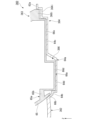
- FIG. 10 is a cross-sectional view showing part of the impeller 60, taken along line XX in FIG.
- arrows AF indicate the flow of air when the impeller 60 rotates.
- a gap G1 is provided between the inner end portion 65b of the blade body portion 65 and the shroud portion 62.
- the gap G1 is connected to the pressure-side space facing the pressure surface 63p and the suction-side space facing the suction surface 63m.
- the gap G1 includes the gap between the inner convex portion 66b and the inner surface of the inner housing portion 64b, the internal space of the inner housing portion 64b, and the gap between the inner end portion 65b and the shroud body portion 62a.
- the gap G1 has an intricate labyrinth shape in the vertical direction Z by inserting the inner convex portion 66b into the inner accommodating portion 64b.
- FIG. 17 is a cross-sectional view showing part of an impeller 560 of a comparative example.
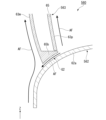
- FIG. 18 is a cross-sectional view showing a part of the impeller 560 of the comparative example, and is a cross-sectional view taken along line XVIII-XVIII in FIG. In FIG. 18, an arrow AF indicates the flow of air when the impeller 560 rotates.
- the shroud portion 562 of the impeller 560 of the comparative example is similar to the shroud portion of the impeller 60 of Embodiment 1, except that the projecting housing portion 564 does not have the inner housing portion 64b. Similar to 62.
- Blade portion 563 of impeller 560 of the comparative example is similar to blade portion 63 of impeller 60 of Embodiment 1, except that projecting portion 566 does not have inner convex portion 66b.
- a gap G2 is provided between the inner end portion 65b of the blade body portion 65 and the inner surface of the shroud body portion 62a. As shown in FIG. 18, the gap G2 extends radially along the inner surface of the shroud body portion 62a.
- the gap G2 is open on both sides in the radial direction, and connects the pressure-side space facing the pressure surface 63p and the suction-side space facing the suction surface 63m. Therefore, in the impeller 560 of the comparative example, as indicated by the arrow AF in FIG. may flow. As a result, there is a problem that the air blowing efficiency of the impeller 560 is lowered.
- each of the plurality of projecting accommodation portions 64 in the shroud portion 62 includes a first accommodation portion 64a and an inner accommodation portion connected to an end portion in the extending direction of the first accommodation portion 64a. 64b and .
- the protruding portion 66 of the blade portion 63 is housed in the first housing portion 64a and is connected to the first convex portion 66a fixed to the shroud portion 62 and the end portion of the first convex portion 66a in the extending direction. and an inner projection 66b housed within 64b.
- the first convex portion 66a is fixed in contact with the lower inner surface of the first accommodating portion 64a.
- the inner convex portion 66b faces the lower inner surface of the inner housing portion 64b with a gap therebetween.
- the gap G1 between the inner end portion 65b of the blade main body portion 65 and the shroud main body portion 62a is reduced.
- the gap can be intricately shaped. Therefore, it is possible to make it difficult for air to pass through the gap G1. As a result, it is possible to prevent air from flowing through the gap G1 from the positive pressure side space facing the positive pressure surface 63p to the negative pressure side space facing the negative pressure surface 63m.
- the centrifugal fan 40 it is possible to suppress a decrease in the air blowing efficiency of the impeller 60.
- the inner convex portion 66b does not come into contact with the lower inner surface of the inner housing portion 64b, the first convex portion 66a is suitable for the lower inner surface of the first housing portion 64a. can be contacted.
- each of the plurality of protruding housing portions 64 is connected as the second housing portion to the radially inner end portion of the extending direction end portions of the first housing portion 64a. It has an inner housing portion 64b.
- the protruding portion 66 has, as a second protruding portion, an inner protruding portion 66b connected to the radially inner end portion of the extending direction end portions of the first protruding portion 66a.
- the inner convex portion 66b is accommodated in the inner accommodating portion 64b. Therefore, it is possible to suppress the flow of air from the positive pressure side to the negative pressure side on the inner side of the first convex portion 66a in the extending direction.
- the inner portion of the blade portion 63 in the extending direction is a portion that separates the air sucked from the intake port 60a, the pressure of the air is likely to increase particularly on the positive pressure side. Therefore, air can be suppressed from flowing from the positive pressure side to the negative pressure side on the inner side of the extension direction of the first convex portion 66a, so that the lowering of the air blowing efficiency of the impeller 60 can be preferably suppressed.
- the lower end of the inner housing portion 64b is located above the lowest portion of the first housing portion 64a.
- the lower end of the inner protrusion 66b is located above the lowest portion of the first protrusion 66a. Therefore, even if the inner housing portion 64b and the inner convex portion 66b are provided, the inner housing portion 64b does not protrude below the first housing portion 64a. Thereby, when the impeller 60 rotates, it is possible to suppress the inner housing portion 64b from acting as air resistance.
- the first convex portion 66a and the first accommodating portion 64a are laser-welded, a glass plate or the like is pressed against the first accommodating portion 64a from below to separate the lower surface of the first convex portion 66a from the first accommodating portion.
- the inner surface of 64a is brought into close contact with the lower surface.
- a glass plate or the like can be preferably pressed against the first housing portion 64a. Therefore, the first convex portion 66a and the first accommodating portion 64a can be preferably fixed by laser welding.
- the entire inner convex portion 66b is arranged away from the inner surface of the inner accommodating portion 64b. That is, the inner convex portion 66b does not contact the inner surface of the inner housing portion 64b. Therefore, when the vane portion 63 is slightly vibrated, it is possible to prevent the vibrating inner convex portion 66b from coming into contact with the inner surface of the inner housing portion 64b. Thereby, it is possible to suppress the generation of noise when the impeller 60 rotates.
- portions of the blade portion 63 other than the portion fixed by laser welding do not contact the shroud portion 62 . Therefore, it is possible to more preferably suppress the vibrating portion of the blade portion 63 from coming into contact with the shroud portion 62, and it is possible to more preferably suppress the generation of noise when the impeller 60 rotates.
- the end portion opposite to the side connected to the first convex portion 66a has a step from the end portion in the extending direction of the blade body portion 65. connected without Therefore, no step occurs between the inner convex portion 66b and the blade body portion 65, and no gap occurs between the step and the shroud body portion 62a. As a result, air does not flow from the positive pressure side to the negative pressure side through the gap between such a step and the shroud body portion 62a. Therefore, it is possible to more preferably suppress the decrease in the air blowing efficiency of the impeller 60 .
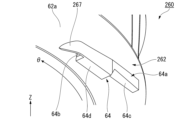
- FIG. 11 is a perspective view showing part of impeller 260 according to the second embodiment.
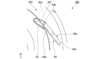
- FIG. 12 is a view of part of impeller 260 in Embodiment 2 as seen from below.
- the description may be omitted by appropriately assigning the same reference numerals to the same configurations as those of the above-described embodiment.
- the shroud portion 262 of the impeller 260 has a covering portion 267 protruding downward from the shroud body portion 62a.
- the covering portion 267 extends from the radially outer side of the inner housing portion 64b to the front side (+ ⁇ side) in the rotational direction while curving radially inward, and covers the inner housing portion 64b from the front side in the rotational direction.
- the end of the covering portion 267 on the rear side ( ⁇ side) in the rotation direction is connected to the radially outer end of the extending direction inner end of the first accommodating portion 64a.
- the lower end of the covering portion 267 is located below the lower end of the inner accommodating portion 64b.
- the lower end of the covering portion 267 is arranged at the same position in the vertical direction Z as the lower end of the inner portion 64d of the first accommodating portion 64a.
- the covering portion 267 is connected to the radially outer side of the inner accommodating portion 64b.
- a portion of the covering portion 267 constitutes a radially outer wall portion of the inner accommodating portion 64b.
- An upper end portion of the covering portion 267 is positioned downward along the outer surface of the shroud main body portion 62a as it goes radially inward. The dimension of the covering portion 267 in the vertical direction Z decreases radially inward.
- shroud portion 262 are the same as the other configurations of the shroud portion 62 in the first embodiment.
- Other configurations of impeller 260 are the same as other configurations of impeller 260 in the first embodiment.
- the shroud portion 262 has a covering portion 267 protruding downward from the shroud body portion 62a.
- the lower end of the covering portion 267 is positioned below the lower end of the inner accommodating portion 64b.
- the covering portion 267 extends from the radially outer side of the inner housing portion 64b to the front side (+ ⁇ side) in the rotational direction while curving radially inward, and covers the inner housing portion 64b from the front side in the rotational direction.
- the covering portion 267 is connected to the radially outer side of the inner accommodating portion 64b. Therefore, compared with the case where the covering portion 267 is made separately from the inner accommodating portion 64b, it is easier to form the covering portion 267 together with the inner accommodating portion 64b. Thereby, the covering portion 267 can be made easily.
- FIG. 13 is a perspective view showing part of impeller 360 according to the third embodiment.
- FIG. 14 is a cross-sectional view showing part of impeller 360 according to the third embodiment.
- FIG. 15 is a perspective view showing a portion of blade portion 363 according to the third embodiment.
- the description may be omitted by appropriately assigning the same reference numerals to the same configurations as those of the above-described embodiment.
- the protruding accommodation portion 364 in the shroud portion 362 of the third embodiment is positioned radially outward of both end portions in the extension direction of the first accommodation portion 64a as the second accommodation portion. It has an outer housing portion 364i connected to the end portion of the housing.
- the outer accommodating portion 364i is connected to the outer end portion of the outer portion 64c in the extending direction.
- the outer accommodating portion 364i extends in the extending direction and has a substantially rectangular parallelepiped box shape that opens upward.
- the lower end of the outer accommodation portion 364i is located above the lower end of the outer portion 64c of the first accommodation portion 64a.
- Other configurations of shroud portion 362 are similar to other configurations of shroud portion 62 in the first embodiment.
- the protruding portion 366 in the blade portion 363 of the third embodiment is positioned radially outward of both end portions in the extending direction of the first protruding portion 66a as the second protruding portion. It has an outer protrusion 366i connected to the end.
- the outer convex portion 366i is connected to the outer end portion of the outer portion 66c in the extending direction.
- the outer convex portion 366i has a substantially rectangular parallelepiped shape extending in the extending direction. In Embodiment 3, the outer convex portion 366i is a solid portion.
- the outer convex portion 366i is housed within the outer housing portion 364i.
- the lower end of the outer protrusion 366i is located above the lower end of the outer portion 66c of the first protrusion 66a.
- the outer protruding portion 366i faces the lower inner surface of the outer housing portion 364i with a gap therebetween.
- Other configurations of blade portion 363 are the same as other configurations of blade portion 63 in the first embodiment.
- Other configurations of impeller 360 are similar to other configurations of impeller 60 in the first embodiment.
- the protruding housing portion 364 has, as the second housing portion, an outer housing portion 364i connected to the radially outer end portion of the extending direction end portions of the first housing portion 64a. .
- the protruding portion 366 has, as a second protruding portion, an outer protruding portion 366i connected to the radially outer end portion of the extending direction end portions of the first protruding portion 66a.
- the outer convex portion 366i is accommodated within the outer accommodating portion 364i. Therefore, it is possible to suppress the flow of air from the positive pressure side to the negative pressure side on the outside in the extension direction of the first convex portion 66a. Thereby, it is possible to more preferably suppress the decrease in the air blowing efficiency of the impeller 360 .
- FIG. 16 is a perspective view showing part of impeller 460 according to the fourth embodiment.
- the description may be omitted by appropriately assigning the same reference numerals to the same configurations as those of the above-described embodiment.
- a shroud portion 462 of an impeller 460 according to the fourth embodiment has a configuration in which the shroud portion 362 according to the third embodiment is provided with the covering portion 267 according to the second embodiment.
- the blade portion in the fourth embodiment is the same as the blade portion 363 in the third embodiment.
- each effect described in the second and third embodiments can be obtained.
- Other configurations of impeller 460 are similar to other configurations of impeller 60 in the first embodiment.
- the projecting accommodation portion in the shroud portion may have at least one of the inner accommodation portion and the outer accommodation portion as the second accommodation portion. That is, the protruding accommodation portion in the shroud portion may have only the outer accommodation portion as the second accommodation portion.
- the inner accommodating portion 64b may not be provided.
- the protrusion height of the second accommodation portion is not particularly limited.
- the first-side (lower) end of the second housing portion is located at the same position in the axial direction (vertical direction Z) as the portion of the first housing portion located closest to the first side, or at the same position in the first housing portion. It may be positioned closer to the first side than the portion positioned closest to the first side.
- the second accommodating portion may have any shape as long as it can accommodate the second convex portion.
- the first accommodating portion of the projecting accommodating portion may have any shape as long as it can accommodate the first convex portion.
- the first housing portion 64a is configured to have the outer portion 64c and the inner portion 64d that have different protrusion heights, but the configuration is not limited to this.
- the first housing portion may have no portions with different protrusion heights, or may have three or more portions with different protrusion heights.
- the protruding portion of the blade portion may have at least one of the inner protruding portion and the outer protruding portion as the second protruding portion. That is, the protruding portion of the blade portion may have only the outer protruding portion as the second protruding portion.
- the inner convex portion 66b may not be provided.
- the protrusion height of the second protrusion is not particularly limited. The first-side (lower) end of the second protrusion is located at the same position in the axial direction (vertical direction Z) as the portion of the first protrusion that is located closest to the first side, or It may be positioned closer to the first side than the portion positioned closest to the first side.
- the second protrusion may have any shape.
- the shape of the inner convex portion 66b in each embodiment described above may be the same shape as the outer convex portion 366i in the third embodiment.
- the second convex portion may have a portion that contacts the inner surface of the second accommodating portion as long as it faces the inner surface of the second accommodating portion located on the first side with a gap therebetween.
- the first convex portion of the projecting portion may have any shape as long as it is fixed to the first accommodating portion.
- the first convex portion 66a is configured to have the outer portion 66c and the inner portion 66d with different protrusion heights, but the present invention is not limited to this.
- the first convex portion may have no portions with different protrusion heights, or may have three or more portions with different protrusion heights.
- a portion of the first convex portion other than the portion fixed to the first accommodating portion may contact the inner surface of the first accommodating portion.
- the first convex portion may be fixed to the shroud portion by a method other than laser welding.
- the covering part of the shroud part does not have to be connected to the inner accommodating part, nor does it have to be connected to the first accommodating part.
- the number of blades and the number of protruding accommodating portions of the shroud are not particularly limited.
- the shape of the blade body is not particularly limited.
- the blade main body may extend in any way when viewed in the axial direction (vertical direction Z).
- the positional relationship between the first blade member and the second blade member that constitute the blade portion may be opposite to the positional relationship in the above-described embodiment. That is, the second blade member may face the negative pressure side.
- Each vane may be an integrally molded solid vane.
- the axial direction of the rotating shaft in the impeller of the present disclosure is not particularly limited, and may extend in a direction other than the vertical direction.
- the impeller of the present disclosure may be mounted on any blower.
- the centrifugal blower of the present disclosure may be mounted on any equipment.
Landscapes
- Engineering & Computer Science (AREA)
- Mechanical Engineering (AREA)
- General Engineering & Computer Science (AREA)
- Chemical & Material Sciences (AREA)
- Combustion & Propulsion (AREA)
- Physics & Mathematics (AREA)
- Thermal Sciences (AREA)
- Structures Of Non-Positive Displacement Pumps (AREA)
Priority Applications (7)
| Application Number | Priority Date | Filing Date | Title |
|---|---|---|---|
| JP2023573776A JP7595792B2 (ja) | 2022-01-17 | 2022-01-17 | 羽根車、遠心送風機、および室内機 |
| GB2406620.1A GB2634360A (en) | 2022-01-17 | 2022-01-17 | Impeller, centrifugal blower, and indoor unit |
| CN202280077606.8A CN118475775A (zh) | 2022-01-17 | 2022-01-17 | 叶轮、离心送风机以及室内机 |
| US18/699,761 US12480521B2 (en) | 2022-01-17 | 2022-01-17 | Impeller, centrifugal blower, and indoor unit |
| PCT/JP2022/001269 WO2023135775A1 (ja) | 2022-01-17 | 2022-01-17 | 羽根車、遠心送風機、および室内機 |
| DE112022006431.5T DE112022006431T5 (de) | 2022-01-17 | 2022-01-17 | Impeller, Radialgebläse und Innenraumeinheit |
| AU2022433486A AU2022433486B2 (en) | 2022-01-17 | 2022-01-17 | Impeller, centrifugal blower, and indoor unit |
Applications Claiming Priority (1)
| Application Number | Priority Date | Filing Date | Title |
|---|---|---|---|
| PCT/JP2022/001269 WO2023135775A1 (ja) | 2022-01-17 | 2022-01-17 | 羽根車、遠心送風機、および室内機 |
Publications (1)
| Publication Number | Publication Date |
|---|---|
| WO2023135775A1 true WO2023135775A1 (ja) | 2023-07-20 |
Family
ID=87278590
Family Applications (1)
| Application Number | Title | Priority Date | Filing Date |
|---|---|---|---|
| PCT/JP2022/001269 Ceased WO2023135775A1 (ja) | 2022-01-17 | 2022-01-17 | 羽根車、遠心送風機、および室内機 |
Country Status (7)
| Country | Link |
|---|---|
| US (1) | US12480521B2 (https=) |
| JP (1) | JP7595792B2 (https=) |
| CN (1) | CN118475775A (https=) |
| AU (1) | AU2022433486B2 (https=) |
| DE (1) | DE112022006431T5 (https=) |
| GB (1) | GB2634360A (https=) |
| WO (1) | WO2023135775A1 (https=) |
Citations (4)
| Publication number | Priority date | Publication date | Assignee | Title |
|---|---|---|---|---|
| JP2007239567A (ja) * | 2006-03-08 | 2007-09-20 | Daikin Ind Ltd | 遠心送風機用羽根車のブレード、ブレード支持回転体、遠心送風機用羽根車、及び遠心送風機用羽根車の製造方法 |
| WO2015104837A1 (ja) * | 2014-01-10 | 2015-07-16 | 三菱電機株式会社 | ファン、遠心ファン及び空気調和装置 |
| JP2016084743A (ja) * | 2014-10-24 | 2016-05-19 | 日清紡メカトロニクス株式会社 | ターボファン及びターボファンの製造方法 |
| JP2021014795A (ja) * | 2019-07-10 | 2021-02-12 | パナソニックIpマネジメント株式会社 | ターボファン |
Family Cites Families (3)
| Publication number | Priority date | Publication date | Assignee | Title |
|---|---|---|---|---|
| JPH06257595A (ja) | 1993-03-05 | 1994-09-13 | Hitachi Ltd | 遠心ファン及びその製造方法 |
| JP4432474B2 (ja) * | 2003-11-27 | 2010-03-17 | ダイキン工業株式会社 | 遠心送風機の羽根車及びそれを備えた遠心送風機 |
| JP5077035B2 (ja) | 2008-04-14 | 2012-11-21 | 株式会社富士通ゼネラル | ターボファン |
-
2022
- 2022-01-17 GB GB2406620.1A patent/GB2634360A/en active Pending
- 2022-01-17 AU AU2022433486A patent/AU2022433486B2/en active Active
- 2022-01-17 JP JP2023573776A patent/JP7595792B2/ja active Active
- 2022-01-17 WO PCT/JP2022/001269 patent/WO2023135775A1/ja not_active Ceased
- 2022-01-17 DE DE112022006431.5T patent/DE112022006431T5/de active Pending
- 2022-01-17 US US18/699,761 patent/US12480521B2/en active Active
- 2022-01-17 CN CN202280077606.8A patent/CN118475775A/zh active Pending
Patent Citations (4)
| Publication number | Priority date | Publication date | Assignee | Title |
|---|---|---|---|---|
| JP2007239567A (ja) * | 2006-03-08 | 2007-09-20 | Daikin Ind Ltd | 遠心送風機用羽根車のブレード、ブレード支持回転体、遠心送風機用羽根車、及び遠心送風機用羽根車の製造方法 |
| WO2015104837A1 (ja) * | 2014-01-10 | 2015-07-16 | 三菱電機株式会社 | ファン、遠心ファン及び空気調和装置 |
| JP2016084743A (ja) * | 2014-10-24 | 2016-05-19 | 日清紡メカトロニクス株式会社 | ターボファン及びターボファンの製造方法 |
| JP2021014795A (ja) * | 2019-07-10 | 2021-02-12 | パナソニックIpマネジメント株式会社 | ターボファン |
Also Published As
| Publication number | Publication date |
|---|---|
| DE112022006431T5 (de) | 2024-12-19 |
| JPWO2023135775A1 (https=) | 2023-07-20 |
| AU2022433486A1 (en) | 2024-05-02 |
| AU2022433486B2 (en) | 2025-05-08 |
| GB2634360A (en) | 2025-04-09 |
| GB202406620D0 (en) | 2024-06-26 |
| JP7595792B2 (ja) | 2024-12-06 |
| US12480521B2 (en) | 2025-11-25 |
| US20240410385A1 (en) | 2024-12-12 |
| CN118475775A (zh) | 2024-08-09 |
Similar Documents
| Publication | Publication Date | Title |
|---|---|---|
| KR100790182B1 (ko) | 송풍 장치 및 공기 조화 장치 | |
| WO2005052377A1 (ja) | 遠心送風機の羽根車及びそれを備えた遠心送風機 | |
| JP7199481B2 (ja) | 送風装置及び冷凍サイクル装置 | |
| JP2007100548A (ja) | 遠心ファン及びこれを用いた空気調和機 | |
| JP2008144753A (ja) | ターボファン及びこれを備えた空気調和機 | |
| JP2003314500A (ja) | 送風機及び冷蔵庫 | |
| CN114930034A (zh) | 离心送风机及空气调节装置 | |
| EP4400777A1 (en) | Ceiling-embedded air conditioner | |
| CN110945250B (zh) | 螺旋桨风扇、送风装置及制冷循环装置 | |
| WO2023135775A1 (ja) | 羽根車、遠心送風機、および室内機 | |
| JP2004353510A (ja) | 遠心送風機及び遠心送風機を備えた空気調和装置 | |
| JP7693023B2 (ja) | 遠心送風機、および室内機 | |
| JP3614649B2 (ja) | 天井埋込型空気調和機 | |
| WO2019163450A1 (ja) | ターボファン、及び空気調和機の室内機 | |
| JP4570048B2 (ja) | 空気調和機の室内機 | |
| JP2001141298A (ja) | 壁埋込型空気調和機 | |
| JP7558434B2 (ja) | 室内機、および空気調和機 | |
| JP7613606B2 (ja) | 冷凍サイクル装置の室外機 | |
| WO2018002987A1 (ja) | 多翼ファン及び空気調和機 | |
| WO2023223383A1 (ja) | クロスフローファン、送風装置及び冷凍サイクル装置 | |
| CN120225810A (zh) | 室内机和空调装置 | |
| CN116848323A (zh) | 风机和室内机 | |
| CN116507809A (zh) | 轴流风扇、送风装置以及制冷循环装置 | |
| JPH1163875A (ja) | 遠心式送風手段を用いた熱交換器 | |
| JP2017048799A (ja) | 遠心送風機 |
Legal Events
| Date | Code | Title | Description |
|---|---|---|---|
| 121 | Ep: the epo has been informed by wipo that ep was designated in this application |
Ref document number: 22920300 Country of ref document: EP Kind code of ref document: A1 |
|
| WWE | Wipo information: entry into national phase |
Ref document number: 2023573776 Country of ref document: JP |
|
| WWE | Wipo information: entry into national phase |
Ref document number: 18699761 Country of ref document: US |
|
| WWE | Wipo information: entry into national phase |
Ref document number: AU2022433486 Country of ref document: AU |
|
| ENP | Entry into the national phase |
Ref document number: 2022433486 Country of ref document: AU Date of ref document: 20220117 Kind code of ref document: A |
|
| ENP | Entry into the national phase |
Ref document number: 202406620 Country of ref document: GB Kind code of ref document: A Free format text: PCT FILING DATE = 20220117 |
|
| WWE | Wipo information: entry into national phase |
Ref document number: 2406620.1 Country of ref document: GB |
|
| WWE | Wipo information: entry into national phase |
Ref document number: 202280077606.8 Country of ref document: CN |
|
| WWE | Wipo information: entry into national phase |
Ref document number: 202427042930 Country of ref document: IN |
|
| WWE | Wipo information: entry into national phase |
Ref document number: 112022006431 Country of ref document: DE |
|
| 122 | Ep: pct application non-entry in european phase |
Ref document number: 22920300 Country of ref document: EP Kind code of ref document: A1 |
|
| WWP | Wipo information: published in national office |
Ref document number: 2406620.1 Country of ref document: GB |
|
| WWG | Wipo information: grant in national office |
Ref document number: 18699761 Country of ref document: US |