WO2023132172A1 - ボールねじ装置 - Google Patents
ボールねじ装置 Download PDFInfo
- Publication number
- WO2023132172A1 WO2023132172A1 PCT/JP2022/044845 JP2022044845W WO2023132172A1 WO 2023132172 A1 WO2023132172 A1 WO 2023132172A1 JP 2022044845 W JP2022044845 W JP 2022044845W WO 2023132172 A1 WO2023132172 A1 WO 2023132172A1
- Authority
- WO
- WIPO (PCT)
- Prior art keywords
- ball screw
- diameter side
- carrier
- fitting
- peripheral surface
- Prior art date
- Legal status (The legal status is an assumption and is not a legal conclusion. Google has not performed a legal analysis and makes no representation as to the accuracy of the status listed.)
- Ceased
Links
Images









Classifications
-
- F—MECHANICAL ENGINEERING; LIGHTING; HEATING; WEAPONS; BLASTING
- F16—ENGINEERING ELEMENTS AND UNITS; GENERAL MEASURES FOR PRODUCING AND MAINTAINING EFFECTIVE FUNCTIONING OF MACHINES OR INSTALLATIONS; THERMAL INSULATION IN GENERAL
- F16H—GEARING
- F16H25/00—Gearings comprising primarily only cams, cam-followers and screw-and-nut mechanisms
- F16H25/18—Gearings comprising primarily only cams, cam-followers and screw-and-nut mechanisms for conveying or interconverting oscillating or reciprocating motions
- F16H25/20—Screw mechanisms
- F16H25/24—Elements essential to such mechanisms, e.g. screws, nuts
-
- B—PERFORMING OPERATIONS; TRANSPORTING
- B60—VEHICLES IN GENERAL
- B60T—VEHICLE BRAKE CONTROL SYSTEMS OR PARTS THEREOF; BRAKE CONTROL SYSTEMS OR PARTS THEREOF, IN GENERAL; ARRANGEMENT OF BRAKING ELEMENTS ON VEHICLES IN GENERAL; PORTABLE DEVICES FOR PREVENTING UNWANTED MOVEMENT OF VEHICLES; VEHICLE MODIFICATIONS TO FACILITATE COOLING OF BRAKES
- B60T13/00—Transmitting braking action from initiating means to ultimate brake actuator with power assistance or drive; Brake systems incorporating such transmitting means, e.g. air-pressure brake systems
- B60T13/74—Transmitting braking action from initiating means to ultimate brake actuator with power assistance or drive; Brake systems incorporating such transmitting means, e.g. air-pressure brake systems with electrical assistance or drive
-
- F—MECHANICAL ENGINEERING; LIGHTING; HEATING; WEAPONS; BLASTING
- F16—ENGINEERING ELEMENTS AND UNITS; GENERAL MEASURES FOR PRODUCING AND MAINTAINING EFFECTIVE FUNCTIONING OF MACHINES OR INSTALLATIONS; THERMAL INSULATION IN GENERAL
- F16C—SHAFTS; FLEXIBLE SHAFTS; ELEMENTS OR CRANKSHAFT MECHANISMS; ROTARY BODIES OTHER THAN GEARING ELEMENTS; BEARINGS
- F16C33/00—Parts of bearings; Special methods for making bearings or parts thereof
- F16C33/30—Parts of ball or roller bearings
- F16C33/58—Raceways; Race rings
- F16C33/581—Raceways; Race rings integral with other parts, e.g. with housings or machine elements such as shafts or gear wheels
-
- F—MECHANICAL ENGINEERING; LIGHTING; HEATING; WEAPONS; BLASTING
- F16—ENGINEERING ELEMENTS AND UNITS; GENERAL MEASURES FOR PRODUCING AND MAINTAINING EFFECTIVE FUNCTIONING OF MACHINES OR INSTALLATIONS; THERMAL INSULATION IN GENERAL
- F16C—SHAFTS; FLEXIBLE SHAFTS; ELEMENTS OR CRANKSHAFT MECHANISMS; ROTARY BODIES OTHER THAN GEARING ELEMENTS; BEARINGS
- F16C35/00—Rigid support of bearing units; Housings, e.g. caps, covers
- F16C35/04—Rigid support of bearing units; Housings, e.g. caps, covers in the case of ball or roller bearings
- F16C35/06—Mounting or dismounting of ball or roller bearings; Fixing them onto shaft or in housing
- F16C35/063—Fixing them on the shaft
-
- F—MECHANICAL ENGINEERING; LIGHTING; HEATING; WEAPONS; BLASTING
- F16—ENGINEERING ELEMENTS AND UNITS; GENERAL MEASURES FOR PRODUCING AND MAINTAINING EFFECTIVE FUNCTIONING OF MACHINES OR INSTALLATIONS; THERMAL INSULATION IN GENERAL
- F16H—GEARING
- F16H25/00—Gearings comprising primarily only cams, cam-followers and screw-and-nut mechanisms
- F16H25/18—Gearings comprising primarily only cams, cam-followers and screw-and-nut mechanisms for conveying or interconverting oscillating or reciprocating motions
- F16H25/20—Screw mechanisms
- F16H25/22—Screw mechanisms with balls, rollers, or similar members between the co-operating parts; Elements essential to the use of such members
-
- F—MECHANICAL ENGINEERING; LIGHTING; HEATING; WEAPONS; BLASTING
- F16—ENGINEERING ELEMENTS AND UNITS; GENERAL MEASURES FOR PRODUCING AND MAINTAINING EFFECTIVE FUNCTIONING OF MACHINES OR INSTALLATIONS; THERMAL INSULATION IN GENERAL
- F16H—GEARING
- F16H25/00—Gearings comprising primarily only cams, cam-followers and screw-and-nut mechanisms
- F16H25/18—Gearings comprising primarily only cams, cam-followers and screw-and-nut mechanisms for conveying or interconverting oscillating or reciprocating motions
- F16H25/20—Screw mechanisms
- F16H25/22—Screw mechanisms with balls, rollers, or similar members between the co-operating parts; Elements essential to the use of such members
- F16H25/2204—Screw mechanisms with balls, rollers, or similar members between the co-operating parts; Elements essential to the use of such members with balls
-
- F—MECHANICAL ENGINEERING; LIGHTING; HEATING; WEAPONS; BLASTING
- F16—ENGINEERING ELEMENTS AND UNITS; GENERAL MEASURES FOR PRODUCING AND MAINTAINING EFFECTIVE FUNCTIONING OF MACHINES OR INSTALLATIONS; THERMAL INSULATION IN GENERAL
- F16H—GEARING
- F16H25/00—Gearings comprising primarily only cams, cam-followers and screw-and-nut mechanisms
- F16H25/18—Gearings comprising primarily only cams, cam-followers and screw-and-nut mechanisms for conveying or interconverting oscillating or reciprocating motions
- F16H25/20—Screw mechanisms
- F16H25/22—Screw mechanisms with balls, rollers, or similar members between the co-operating parts; Elements essential to the use of such members
- F16H25/2204—Screw mechanisms with balls, rollers, or similar members between the co-operating parts; Elements essential to the use of such members with balls
- F16H25/2214—Screw mechanisms with balls, rollers, or similar members between the co-operating parts; Elements essential to the use of such members with balls with elements for guiding the circulating balls
- F16H25/2223—Cross over deflectors between adjacent thread turns, e.g. S-form deflectors connecting neighbouring threads
-
- F—MECHANICAL ENGINEERING; LIGHTING; HEATING; WEAPONS; BLASTING
- F16—ENGINEERING ELEMENTS AND UNITS; GENERAL MEASURES FOR PRODUCING AND MAINTAINING EFFECTIVE FUNCTIONING OF MACHINES OR INSTALLATIONS; THERMAL INSULATION IN GENERAL
- F16C—SHAFTS; FLEXIBLE SHAFTS; ELEMENTS OR CRANKSHAFT MECHANISMS; ROTARY BODIES OTHER THAN GEARING ELEMENTS; BEARINGS
- F16C2361/00—Apparatus or articles in engineering in general
- F16C2361/61—Toothed gear systems, e.g. support of pinion shafts
-
- F—MECHANICAL ENGINEERING; LIGHTING; HEATING; WEAPONS; BLASTING
- F16—ENGINEERING ELEMENTS AND UNITS; GENERAL MEASURES FOR PRODUCING AND MAINTAINING EFFECTIVE FUNCTIONING OF MACHINES OR INSTALLATIONS; THERMAL INSULATION IN GENERAL
- F16H—GEARING
- F16H25/00—Gearings comprising primarily only cams, cam-followers and screw-and-nut mechanisms
- F16H25/18—Gearings comprising primarily only cams, cam-followers and screw-and-nut mechanisms for conveying or interconverting oscillating or reciprocating motions
- F16H25/20—Screw mechanisms
- F16H2025/2062—Arrangements for driving the actuator
- F16H2025/2081—Parallel arrangement of drive motor to screw axis
-
- F—MECHANICAL ENGINEERING; LIGHTING; HEATING; WEAPONS; BLASTING
- F16—ENGINEERING ELEMENTS AND UNITS; GENERAL MEASURES FOR PRODUCING AND MAINTAINING EFFECTIVE FUNCTIONING OF MACHINES OR INSTALLATIONS; THERMAL INSULATION IN GENERAL
- F16H—GEARING
- F16H25/00—Gearings comprising primarily only cams, cam-followers and screw-and-nut mechanisms
- F16H25/18—Gearings comprising primarily only cams, cam-followers and screw-and-nut mechanisms for conveying or interconverting oscillating or reciprocating motions
- F16H25/20—Screw mechanisms
- F16H2025/2062—Arrangements for driving the actuator
- F16H2025/2096—Arrangements for driving the actuator using endless flexible members
Definitions
- the present disclosure relates to a ball screw device.
- a ball screw device allows balls to roll between the screw shaft and the nut, so it is more efficient than a sliding screw device that directly contacts the screw shaft and the nut. For this reason, ball screw devices are used in various mechanical devices such as electric brake devices and automatic manual transmissions (AMT) of automobiles, positioning devices of machine tools, etc., in order to convert rotary motion of a drive source such as an electric motor into linear motion. built in.
- AMT automatic manual transmissions
- a ball screw device includes a screw shaft having a spiral shaft-side ball screw groove on its outer peripheral surface, a nut having a spiral nut-side ball screw groove on its inner peripheral surface, and a shaft-side ball screw groove and a nut-side ball screw groove. and a plurality of balls disposed between.
- a ball screw device one of the screw shaft and the nut is used as a rotary motion element, and the other of the screw shaft and the nut is used as a linear motion element, depending on the application.
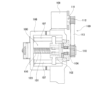
- FIG. 14 shows a conventional ball screw device 100 described in Japanese Patent Laid-Open No. 2009-286137.
- the ball screw device 100 includes a screw shaft 101, a nut 102, and a plurality of balls (not shown).
- the threaded shaft 101 has a threaded portion 103 and a fitting shaft portion 104 arranged adjacent to one side of the threaded portion 103 in the axial direction.
- a spiral shaft-side ball screw groove 105 is formed on the outer peripheral surface of the threaded portion 103 .
- the fitting shaft portion 104 has an outer diameter smaller than that of the threaded portion 103 .
- the threaded shaft 101 is arranged coaxially with the nut 102 with the threaded portion 103 inserted inside the nut 102 .
- the nut 102 has a cylindrical shape.
- a spiral nut-side ball screw groove (not shown) is formed on the inner peripheral surface of the nut 102 .
- Nut 102 engages a plurality of guide rods 107 supported against housing 106 . This prevents the nut 102 from rotating.
- the shaft-side ball screw groove 105 and the nut-side ball screw groove are arranged so as to face each other in the radial direction, forming a spiral load path.
- a start point and an end point of the load path are connected by circulation means (not shown). Therefore, the ball that has reached the end point of the load path is returned to the start point of the load path through the circulation means.
- the start point and end point of the load path are interchanged according to the relative displacement direction of the screw shaft 101 and the nut 102 in the axial direction, that is, the relative rotation direction of the screw shaft 101 and the nut 102 .
- the rotation of the electric motor 108 which is the drive source, is reduced by the pulley device 109 and transmitted to the screw shaft 101.
- the driven pulley 110 is fitted to the fitting shaft portion 104 provided at one end portion of the screw shaft 101 in the axial direction so that the driven pulley 110 cannot rotate relative to the fitting shaft portion 104 .
- a drive pulley 112 is fitted to the tip of the motor shaft 111 of the electric motor 108 so as not to be relatively rotatable.
- a belt 113 is stretched between the drive pulley 112 and the driven pulley 110 .
- a pulley device is used as in the conventional structure described in Japanese Patent Laid-Open No. 2009-286137, or a spur gear type reduction mechanism is used. is considered to be used.
- FIG. 15 is an undisclosed ball screw device that the inventors considered prior to completing the ball screw device of the present disclosure.
- a carrier 115 constituting a planetary speed reduction mechanism 114 is fitted to one end in the axial direction of a screw shaft 101a constituting a ball screw device 100a so as not to rotate relative to it.
- a fitting shaft portion 104a formed at one end in the axial direction of the screw shaft 101a is spline-fitted into a mounting hole 116 formed in the center portion of the carrier 115 in the radial direction.
- a plurality of planetary gears 117 are rotatably supported with respect to the carrier 115 .
- a pinion pin 119 is inserted and supported through a plurality of support holes 118 formed in a radially intermediate portion of the carrier 115
- a planetary gear 117 is rotatably supported around the pinion pin 119 .
- a plurality of planetary gears 117 are arranged between a sun gear 120 fixed to the tip of the motor shaft 111a of the electric motor 108a and a ring gear 121 arranged coaxially with the sun gear 120 and fixed to a housing 124. are placed.
- a plurality of planetary gears 117 mesh with the sun gear 120 and the ring gear 121 respectively.
- the carrier 115 fixed to the fitting shaft portion 104a of the screw shaft 101a is rotatably supported with respect to the housing 124 using the rolling bearing 122. Therefore, the axial force transmitted to carrier 115 is supported by housing 124 via rolling bearing 122 .
- an outward flange-like flange 123 is provided on a part of the outer peripheral surface of the carrier 115.
- the flange portion 123 is brought into contact with the rolling bearing 122 .
- the carrier 115 is rotatably supported with respect to the housing 124 by using the rolling bearing 122 which is separate from the carrier 115. Therefore, the number of parts is increased and the ball screw device 100a is Assemblability tends to deteriorate.
- An object of the present disclosure is to provide a ball screw device that can reduce the number of parts and improve the ease of assembly even when adopting a structure that rotationally drives a screw shaft using a planetary speed reduction mechanism. aim.
- a ball screw device includes a screw shaft, a nut, a plurality of balls, a carrier, and a rolling bearing.
- the screw shaft has a threaded portion having a helical shaft-side ball screw groove on its outer peripheral surface, and a fitting shaft portion arranged on one side of the threaded portion in the axial direction, and rotates during use.
- the nut has a helical nut-side ball screw groove on its inner peripheral surface and moves linearly during use.
- the plurality of balls are arranged between the shaft-side ball screw groove and the nut-side ball screw groove.
- the carrier constitutes a planetary speed reduction mechanism, is fixed relative to the fitting shaft so as not to rotate, and drives the screw shaft to rotate.
- the rolling bearing includes an outer ring having an outer ring raceway on its inner peripheral surface, an inner ring raceway provided in a portion facing the outer ring raceway in a radial direction, and a rollable arrangement between the outer ring raceway and the inner ring raceway. and a plurality of rolling elements arranged to rotatably support the carrier.
- the fitting shaft portion has an inner diameter side engaging portion on the outer peripheral surface.
- the carrier has a mounting hole in the radially central portion thereof into which the fitting shaft portion can be inserted, and the mounting hole is engaged with the inner diameter side engaging portion on the inner peripheral surface so as not to rotate relative to each other. It has an outer diameter side engaging portion that
- the inner ring raceway is directly formed on the outer peripheral surface of the carrier. That is, it can also be said that the inner ring, which constitutes the rolling bearing and has the inner ring raceway, is configured integrally with the carrier.
- the fitting shaft portion may have an inner diameter side fitting surface portion on a portion of the outer peripheral surface that is axially deviated from the inner diameter side engaging portion
- the mounting hole may have an outer diameter side fitting surface portion that is spigot-fitted with the inner diameter side fitting surface portion in a portion of the inner peripheral surface that is axially deviated from the outer diameter side engaging portion.
- the inner diameter side fitting surface portion can be press-fitted into the outer diameter side fitting surface portion.
- the inner diameter side fitting surface portion and the outer diameter side fitting surface portion can be fitted with a clearance fit with a minute clearance.
- the inner diameter side fitting surface portion and the outer diameter side fitting surface portion are fitted with a clearance fit with a minute clearance, for example, the outer peripheral surface of the fitting shaft portion or the inner periphery of the mounting hole A retaining ring is engaged with the surface, and the retaining ring prevents the fitting shaft portion from slipping out of the mounting hole in the axial direction.
- a crimped portion may be formed on the outer peripheral surface of the fitting shaft portion, and the crimping portion may prevent the fitting shaft portion from slipping out of the mounting hole in the axial direction.
- the carrier may have a symmetrical shape with respect to the axial direction.
- the engagement portion between the inner diameter side engagement portion and the outer diameter side engagement portion may have a radial interference in a part of the axial direction.
- the carrier may have support holes for inserting and supporting pinion pins constituting the planetary speed reduction mechanism at a plurality of locations in the circumferential direction of the radial intermediate portion. .
- the support hole can be configured by a through hole axially penetrating the carrier.
- the carrier has a protruding portion that protrudes toward the one axial side on a portion of the side surface on the one axial side that includes the opening of the support hole. be able to.
- the projecting portion may have an annular shape.
- a ball screw device employs a structure in which a screw shaft is rotationally driven via a planetary speed reduction mechanism. ing.
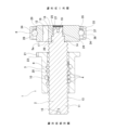
- FIG. 1 is a cross-sectional view showing an example of a structure in which a ball screw device and a planetary speed reduction mechanism of a first example of an embodiment of the present disclosure are combined.
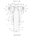
- FIG. 2 is a cross-sectional view showing the ball screw device of the first example.
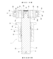
- FIG. 3 is a diagram corresponding to FIG. 2 showing a ball screw device of a second example of the embodiment of the present disclosure.
- FIG. 4 is a diagram corresponding to FIG. 2 showing a ball screw device of a third example of the embodiment of the present disclosure.
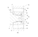
- 5 is a partially enlarged view of FIG. 4.
- FIG. FIG. 6 is a diagram corresponding to FIG. 2 showing a ball screw device of a fourth example of the embodiment of the present disclosure. 7 is a partially enlarged view of FIG. 6.
- FIG. FIG. 8 is a partial enlarged view of an end view of the fitting portion between the fitting shaft portion of the screw shaft and the mounting hole of the carrier in the ball screw device of the fourth example, viewed from one side in the axial direction.
- FIG. 9 is a diagram corresponding to FIG. 2 showing a ball screw device of a fifth example of the embodiment of the present disclosure.
- FIG. 10 is a diagram corresponding to FIG. 2 showing a ball screw device of a sixth example of the embodiment of the present disclosure.
- 11 is a partially enlarged view of FIG. 10.
- FIG. FIG. 12 is an enlarged cross-sectional view of the fitting shaft portion shown in FIG. 11 with the carrier omitted.
- FIG. 13 is a diagram corresponding to FIG.
- FIG. 14 is a sectional view showing a conventional ball screw device in which a ball screw device and a pulley device are combined.
- FIG. 15 is a cross-sectional view showing a ball screw device having an undisclosed structure in which a ball screw device and a planetary speed reduction mechanism are combined.
- FIGS. 1 and 2 show an example of a structure in which a ball screw device and a planetary speed reduction mechanism of the first embodiment of the present disclosure are combined.
- the ball screw device 1 of this example is incorporated in, for example, an electric brake booster device and used for applications such as converting rotary motion of an electric motor, which is a drive source, into linear motion to operate a piston of a hydraulic cylinder.
- the ball screw device 1 includes a screw shaft 2, a nut 3, a plurality of balls 4, a carrier 5, and rolling bearings 6.
- the screw shaft 2 is a rotary motion element that is driven to rotate via a planetary speed reduction mechanism 8 by an electric motor 7, which is a drive source, and rotates during use.
- the screw shaft 2 is inserted through the inside of the nut 3 and arranged coaxially with the nut 3 .
- the nut 3 is a linear motion element that is prevented from co-rotating with respect to the screw shaft 2 by a non-illustrated anti-rotation mechanism and moves linearly during use. That is, the ball screw device 1 of this example is used in a mode in which the screw shaft 2 is rotationally driven and the nut 3 is linearly moved.
- a spiral load path 9 is provided between the outer peripheral surface of the screw shaft 2 and the inner peripheral surface of the nut 3 .
- a plurality of balls 4 are rotatably arranged in the load path 9 .
- the balls 4 that have reached the end point of the load path 9 are returned to the starting point of the load path 9 through the circulation grooves 10 formed on the inner peripheral surface of the nut 3 .
- the axial direction, radial direction, and circumferential direction refer to the axial direction, radial direction, and circumferential direction with respect to the screw shaft 2 unless otherwise specified.
- the one axial side refers to the right side in FIGS. 1 and 2
- the other axial side refers to the left side in FIGS.
- the threaded shaft 2 is made of metal, and has a threaded portion 11 and a fitting shaft portion 12 adjacently arranged on one axial side of the threaded portion 11 .
- the threaded portion 11 and the fitting shaft portion 12 are coaxially arranged and integrally formed with each other.
- the fitting shaft portion 12 has an outer diameter smaller than that of the threaded portion 11 .
- the screw portion 11 has a spiral shaft-side ball screw groove 13 on its outer peripheral surface.
- the shaft-side ball screw groove 13 is formed by subjecting the outer peripheral surface of the threaded portion 11 to grinding, cutting, or rolling. In this example, the number of threads of the shaft-side ball screw groove 13 is one.
- the cross-sectional groove shape (groove bottom shape) of the shaft-side ball screw groove 13 has a Gothic arch shape or a circular arc shape.
- the threaded portion 11 has an abutment surface 14 having a ring shape on one end surface in the axial direction.
- the abutment surface 14 is a flat surface that exists on a virtual plane perpendicular to the central axis of the screw shaft 2 .
- the threaded portion 11 has a bottomed first center hole 15 in the radially central portion of the end face on the other side in the axial direction.
- the fitting shaft portion 12 has an inner diameter side engaging portion 16 on one axial side portion (tip side portion) of the outer peripheral surface, and a portion of the outer peripheral surface axially displaced from the inner diameter side engaging portion 16. It has an inner diameter side fitting surface portion 17 in a certain axial direction other side portion (base end side portion). In this example, the axial dimension of the inner diameter side engaging portion 16 is larger than the axial dimension of the inner diameter side fitting surface portion 17 .
- the inner diameter side engaging portion 16 has male spline teeth 18 over the entire circumference. That is, in this example, the inner diameter side engaging portion 16 constitutes the male spline portion.
- the male spline teeth 18 are composed of involute spline teeth, but the male spline teeth can also be composed of angular spline teeth.
- the inner diameter side fitting surface portion 17 has a cylindrical outer peripheral surface whose outer diameter does not change over the axial direction.
- the outer diameter of the inner diameter side fitting surface portion 17 is larger than the addendum circle diameter of the male spline tooth 18 forming the inner diameter side engaging portion 16 and smaller than the outer diameter of the threaded portion 11 .
- the fitting shaft portion 12 has a bottomed second center hole 19 in the radial center portion of the end surface on one axial side.
- the second center hole 19 and the first center hole 15 provided in the threaded portion 11 are arranged coaxially with each other.
- the bottom (rear end) of the second center hole 19 is located in the axially intermediate portion of the fitting shaft portion 12 and radially inside the inner diameter engaging portion 16 .
- the screw shaft 2 is arranged coaxially with the nut 3 with the threaded portion 11 inserted inside the nut 3 .
- the screw shaft 2 is composed of a threaded portion 11 and a fitting shaft portion 12.
- the screw shaft is a support shaft portion (second fitting shaft portion) for externally fitting and fixing other members. ), etc., can also be provided.
- the nut 3 is made of metal and has a cylindrical shape as a whole.
- the nut 3 has a helical nut-side ball screw groove 20 and a circulation groove 10 on its inner peripheral surface.
- the nut-side ball screw groove 20 has a helical shape and is formed by subjecting the inner peripheral surface of the nut 3 to grinding, cutting, rolling tapping, or cutting tapping, for example.
- the nut-side ball screw groove 20 has the same lead as the shaft-side ball screw groove 13 . Therefore, when the threaded portion 11 of the screw shaft 2 is inserted through the nut 3, the shaft-side ball screw groove 13 and the nut-side ball screw groove 20 are arranged so as to face each other in the radial direction, forming a spiral shape.
- a load path 9 is configured.
- the number of threads of the nut-side ball screw groove 20 is one, like the shaft-side ball screw groove 13 .
- the cross-sectional groove shape of the nut-side ball screw groove 20 is also a Gothic arch shape or a circular arc shape, like the shaft-side ball screw groove 13 .
- the circulation groove 10 has a substantially S-shape and is formed on the inner peripheral surface of the nut 3 by forging such as cold forging.
- the circulation groove 10 smoothly connects axially adjacent portions of the nut-side ball screw groove 20 and connects the start point and the end point of the load path 9 . Therefore, the ball 4 that has reached the end point of the load path 9 is returned to the start point of the load path 9 through the circulation groove 10 .
- the start point and the end point of the load path 9 are interchanged according to the direction of relative displacement between the screw shaft 2 and the nut 3 in the axial direction (relative rotation direction between the screw shaft 2 and the nut 3).
- the circulation groove 10 has a substantially semicircular cross-sectional shape.
- the circulation groove 10 has a groove width slightly larger than the diameter of the balls 4, and has a groove depth that allows the balls 4 moving in the circulation groove 10 to climb over the threads of the shaft-side ball screw groove 13. ing.
- the nut 3 has an outward flange-like flange 21 at one end in the axial direction of the outer peripheral surface.
- the flange 21 is engaged with anti-rotation members (not shown) provided on a fixed member such as the housing 22 at a plurality of locations (three locations in this example) in the circumferential direction. is provided with an engaging groove 23 of .
- anti-rotation members not shown
- a fixed member such as the housing 22
- Various conventionally known structures can be employed as the nut anti-rotation mechanism.
- a small-diameter portion having a smaller outer diameter than the portion adjacent to the one axial side can be formed at the end portion on the other axial side of the outer peripheral surface of the nut 3 .
- a fitting cylinder such as a piston (not shown) can be externally fitted and fixed to the small diameter portion.
- Balls 4 are steel balls having a predetermined diameter, and are arranged in load path 9 and circulation groove 10 so as to be able to roll.
- the balls 4 arranged in the load path 9 roll while being subjected to a compressive load, whereas the balls 4 arranged in the circulation groove 10 are pushed by the succeeding balls 4 and roll without being subjected to a compressive load. move.
- the carrier 5 constitutes a planetary speed reduction mechanism 8 and transmits torque input from an electric motor 7 as a drive source to the screw shaft 2 to rotationally drive the screw shaft 2 .
- the carrier 5 has a circular flat plate shape, and has a mounting hole 24 penetrating in the axial direction at the center in the radial direction.
- the mounting hole 24 has an outer diameter side engaging portion 25 on one side in the axial direction of the inner peripheral surface. It has an outer diameter side fitting surface portion 26 on the other side portion.
- the outer diameter side engaging portion 25 has female spline teeth 27 over the entire circumference. That is, in this example, the outer diameter side engaging portion 25 constitutes the female spline portion.
- the female spline teeth 27 are composed of involute spline teeth, but the female spline teeth can also be composed of angular spline teeth.
- the outer diameter side fitting surface portion 26 has a cylindrical outer peripheral surface whose inner diameter does not change along the axial direction.
- the inner diameter of the outer diameter side fitting surface portion 26 is larger than the root circle diameter of the female spline tooth 27 constituting the outer diameter side engaging portion 25 and slightly smaller than the outer diameter of the inner diameter side fitting surface portion 17 . .
- the carrier 5 By inserting the fitting shaft portion 12 of the screw shaft 2 into the mounting hole 24 , the carrier 5 is externally fitted and fixed to the fitting shaft portion 12 . Further, the abutment surface 14 provided on the threaded portion 11 of the screw shaft 2 abuts against the side surface of the carrier 5 on the other side in the axial direction, thereby positioning the screw shaft 2 and the carrier 5 in the axial direction. .
- the outer diameter side engaging portion 25 and the inner diameter side engaging portion 16 are engaged so as not to rotate relative to each other.
- the female spline teeth 27 of the outer diameter side engaging portion 25 and the male spline teeth 18 of the inner diameter side engaging portion 16 are spline-engaged. This allows the screw shaft 2 to be rotationally driven via the carrier 5 .
- the outer diameter side fitting surface portion 26 and the inner diameter side fitting surface portion 17 are spigot-fitted. This increases the degree of coaxiality between the screw shaft 2 and the carrier 5 . Since the inner diameter side fitting surface portion 17 is press-fitted into the outer diameter side fitting surface portion 26 , the fitting shaft portion 12 is prevented from slipping out of the mounting hole 24 to the other side in the axial direction.
- the inner diameter of the outer diameter side fitting surface portion is made slightly larger than the outer diameter of the inner diameter side fitting surface portion so that the outer diameter side fitting surface portion and the inner diameter side fitting surface portion are slightly It is also possible to fit them by clearance fitting with a gap.
- An inner ring raceway 28 that constitutes the rolling bearing 6 is directly formed in the axially intermediate portion (the axially central portion in this example) of the outer peripheral surface of the carrier 5 . That is, the carrier 5 functions not only as a component of the planetary speed reduction mechanism 8 but also as an inner ring forming the rolling bearing 6 . In other words, it can be said that the carrier and the inner ring forming the rolling bearing are integrally formed.
- the rolling bearing 6 is configured by a deep groove ball bearing capable of supporting a radial load and an axial load in both directions, so the inner ring raceway 28 is configured by a deep groove having a concave arc shape in cross section.
- the portions outside the inner ring raceway 28 on both sides in the axial direction are formed into a partially cylindrical surface.
- seal concave grooves over the entire circumference on both sides in the axial direction of the outer peripheral surface of the carrier so that the inner diameter side end of the seal ring, which is an optional element for sealing the rolling bearing, is brought into sliding contact. can.
- the carrier 5 has support holes 29 for inserting and supporting the pinion pins 41 constituting the planetary speed reduction mechanism 8 at a plurality of locations (three locations in this example) in the circumferential direction of the radially intermediate portion.
- the plurality of support holes 29 are arranged at regular intervals in the circumferential direction. Further, the respective central axes of the plurality of support holes 29 are arranged parallel to each other.
- Each support hole 29 is formed by a through hole that penetrates the carrier 5 in the axial direction. That is, the support hole 29 is open not only on one side surface of the carrier 5 in the axial direction, but also on the other side surface of the carrier 5 in the axial direction.
- the support hole can also be configured by a bottomed hole that is open only on one side surface of the carrier in the axial direction.
- the inner diameter of the support hole 29 is constant over the axial direction.
- the diameter of an imaginary circle passing through the radially inner end of each of the plurality of support holes 29 (inscribed circle diameter) is substantially the same as the outer diameter of the threaded portion 11 .
- the diameter of the virtual circle passing through the radially outer end of each of the plurality of support holes 29 (the circumscribed circle diameter) is slightly larger than the outer diameter of the portion of the nut 3 axially deviating from the flange 21. Only small.
- the carrier 5 is directed toward the one axial side from the radially outer and inner portions in the radial intermediate portion including the openings of the plurality of support holes 29 . It has an overhang portion 30 that overhangs.
- the projecting portion 30 has an annular shape.
- the inner diameter of the projecting portion 30 is smaller than the diameter of the imaginary cylindrical surface passing through the groove bottom of the shaft-side ball screw groove 13 .
- the outer diameter of the projecting portion 30 is substantially the same as the outer diameter of the portion of the nut 3 that is axially deviated from the collar portion 21 and is smaller than the outer diameter of the groove bottom portion of the inner ring raceway 28 .
- a side surface (tip surface) on one side in the axial direction of the projecting portion 30 is a flat surface that exists on a virtual plane perpendicular to the central axis of the carrier 5 .
- the protruding portion 30 and the portion of the side surface on one axial side of the carrier 5 that is radially outward of the protruding portion 30 are inclined in a direction in which the outer diameter increases toward the other axial side. They are connected by an outer diameter side connection surface 31 .
- the overhanging portion 30 and the portion of the side surface on the one axial side of the carrier 5 that is located radially inward of the overhanging portion 30 are inclined in a direction in which the inner diameter decreases toward the other axial side. , are connected by a connecting surface 32 on the inner diameter side.
- the side surface of the carrier 5 on the other side in the axial direction is a flat surface existing on a virtual plane perpendicular to the central axis of the carrier 5 .
- induction hardening and tempering are applied to the outer peripheral surface on which the inner ring raceway 28 is formed, and a heat-treated hardened layer is formed.
- the heat-hardened layer is not formed on the side surface of the carrier 5 on one side in the axial direction and the side surface on the other side in the axial direction.
- the rolling bearing 6 rotatably supports the carrier 5 , which is externally fitted onto the screw shaft 2 , with respect to the housing 22 , and supports the axial force transmitted to the carrier 5 by the housing 22 .
- the rolling bearing 6 is configured by a deep groove ball bearing capable of supporting a radial load and an axial load in both directions.
- rolling bearings such as multi-point contact ball bearings such as four-point contact ball bearings, double-row deep groove ball bearings, double-row angular contact ball bearings, tapered rolling bearings, double-row tapered roller bearings, etc. , any bearing capable of supporting radial and axial loads can be used.
- the rolling bearing 6 includes an outer ring 33 , an inner ring raceway 28 , multiple rolling elements 34 and a retainer 35 .
- the outer ring 33 has an annular shape, and has an outer ring raceway 36 in the axial center of the inner peripheral surface.
- the outer ring 33 is internally fitted and fixed to the housing 22 and does not rotate during use.
- the outer ring raceway 36 is formed of a deep groove having a concave arc shape in cross section. It is also possible to provide a retaining ring that is engaged with a portion of the inner peripheral surface of the housing 22 that is axially deviated from the portion where the outer ring 33 is internally fitted, and the retaining ring prevents the outer ring 33 from coming off. can.
- the portions outside the outer ring raceway 36 in the axial direction are configured in a partially cylindrical surface shape.
- locking grooves are formed along the entire circumference on both sides in the axial direction of the inner peripheral surface of the outer ring.
- the inner ring raceway 28 that constitutes the rolling bearing 6 is formed directly in the axially intermediate portion of the outer peripheral surface of the carrier 5 that faces the outer ring raceway 36 in the radial direction, and the inner ring is omitted.
- the plurality of rolling elements 34 are made of steel or ceramics, and are arranged between the outer ring raceway 36 and the inner ring raceway 28 at regular intervals in the circumferential direction. Balls are used as the rolling elements 34 in this example.
- the retainer 35 has an annular shape and has pockets 37 at regular intervals in the circumferential direction.
- a rolling element 34 is rotatably held inside the pocket 37 .
- a planetary speed reduction mechanism 8 is used to transmit the rotation of the electric motor 7 to the screw shaft 2 that constitutes the ball screw device 1 .
- the planetary speed reduction mechanism 8 includes a sun gear 38 , a plurality of planetary gears 39 , a ring gear 40 , a carrier 5 and pinion pins 41 .
- the sun gear 38 is fixed to the tip of the motor shaft (sun gear shaft) 42 of the electric motor 7 .
- a ring gear 40 is arranged coaxially with the sun gear 38 and is internally fitted and fixed to the housing 22 .
- the housing 22 may be divided into two parts, and the part in which the ring gear 40 is fitted and the part in which the outer ring 33 constituting the rolling bearing 6 is fitted may be formed of separate members.
- a plurality of (three in this example) planetary gears 39 are arranged at regular intervals in the circumferential direction and are rotatably supported on the carrier 5 .
- the other half of the pinion pin 41 in the axial direction is press-fitted into the support hole 29 formed in the carrier 5 , and the one half of the pinion pin 41 in the axial direction is pushed out from the support hole 29 in the axial direction. It protrudes to one side.
- a planetary gear 39 is rotatably supported via a slide bearing or needle bearing (C&R) (not shown).
- the method of fixing the pinion pin to the support hole is not particularly limited, and a fixing structure using caulking or locking pins can also be adopted.
- a fixing structure using caulking or locking pins can also be adopted.
- a structure in which the pinion pin is supported on both sides can be adopted.
- the number of planetary gears is not limited to three, and may be two or four or more.
- the planetary gear 39 meshes with the sun gear 38 and the ring gear 40 respectively.
- the screw shaft 2 is rotationally driven via the planetary speed reduction mechanism 8 by the electric motor 7 as a drive source, thereby linearly moving the nut 3 .
- the electric motor 7 is energized and the sun gear 38 is rotated in a predetermined direction
- the planetary gear 39 revolves around the sun gear 38 while rotating.
- the orbital motion of the planetary gear 39 is transmitted to the screw shaft 2 via the carrier 5 and rotates the screw shaft 2 in a predetermined direction, thereby linearly moving the nut 3 .
- the nut 3 moves relatively to the one side in the axial direction with respect to the screw shaft 2, turning the sun gear 38 toward the other side in the circumferential direction. , the nut 3 moves relative to the screw shaft 2 in the other axial direction.
- the screw shaft 2 can be rotationally driven via the planetary speed reduction mechanism 8 by the electric motor 7 as the drive source. Stroke ends associated with the relative movement of the nut 3 to the one axial side and the other axial side with respect to the screw shaft 2 can be regulated using various conventionally known stroke limiting mechanisms.
- the ball screw device 1 of this example employs a structure in which the screw shaft 2 is rotationally driven using the planetary speed reduction mechanism 8, the number of parts is reduced and the assembly efficiency is improved. is planned.
- the inner ring raceway 28 forming the rolling bearing 6 is directly formed on the outer peripheral surface of the carrier 5, the inner ring forming the rolling bearing 6 can be omitted. Therefore, compared to the structure shown in FIG. 15, in which an inner ring separate from the carrier is externally fitted and fixed to the carrier, the number of parts is reduced, the number of assembly man-hours is reduced, and , and improved assembly. Moreover, in this example, there is no need to form a collar portion for transmitting force in the axial direction on the outer peripheral surface of the carrier 5, and the number of processing steps can be reduced accordingly.
- the carrier 5 since the carrier 5 does not need a flange, it is sufficient to form the heat-hardened layer only on the outer peripheral surface including the inner ring raceway 28 . Therefore, when the axial side surface of the carrier 5 is drilled to form the support holes 29, there is no need to remove the heat-hardened layer, and the number of processing steps can be reduced. can.
- an inner diameter side fitting surface portion 17 having a cylindrical outer peripheral surface formed on the fitting shaft portion 12 is formed. and the outer diameter side fitting surface portion 26 having a cylindrical inner peripheral surface formed in the mounting hole 24 of the carrier 5 are spigot-fitted. can be done. Further, since the inner diameter side fitting surface portion 17 is press-fitted into the outer diameter side fitting surface portion 26, the fitting portion between the inner diameter side fitting surface portion 17 and the outer diameter side fitting surface portion 26 causes the fitting shaft portion 12 to move. It is also possible to prevent it from slipping out of the mounting hole 24 to the other side in the axial direction.
- the outer diameter side fitting surface portion 26 and the inner diameter side fitting surface portion 17 are spigot joints.
- the fitting portion and the portion where the pinion pin 41 is press-fitted into the support hole 29 can be prevented from overlapping in the radial direction.
- the axial position of the portion where the outer diameter side fitting surface portion 26 and the inner diameter side fitting surface portion 17 are spigot-fitted and the portion of the support hole 29 into which the pinion pin 41 is press-fitted. can be offset.
- the portion of the carrier 5 that exists around the outer diameter side fitting surface portion 26 is increased in diameter (diameter direction outer side). Movement of the material) of the support hole 29 into which the pinion pin 41 is press-fitted can be less affected on the inner diameter change. Further, as the pinion pin 41 is press-fitted into the one axial side portion of the support hole 29 , the portion of the carrier 5 existing radially inside the one axial side portion of the support hole 29 is reduced in diameter (diameter Even when the movement of the material toward the inside of the direction occurs, the influence on the change in the inner diameter of the outer diameter side fitting surface portion 26 can be reduced.
- an overhang portion 30 having a flat surface on the one axial side surface is formed in a radially intermediate portion including the opening of the support hole 29.
- the side surface of the planetary gear 39 on the other side in the axial direction and the side surface on the one side in the axial direction of the projecting portion 30 are in direct contact with each other.
- another member such as a slide washer may be interposed between the side surface of the projecting portion 30 and one side surface in the axial direction.
- the carrier 5 since the carrier 5 is rotatably supported by the housing 22 using the rolling bearing 6 , the axial force transmitted to the carrier 5 is transferred to the housing 22 via the rolling bearing 6 .
- the reaction force in the axial direction acting on the screw shaft 2 from the nut 3 via the balls 4 is applied to the meshing portion between the planetary gear 39 and the sun gear 38 and the planetary gears. It is possible to prevent transmission to the meshing portion between 39 and ring gear 40 .
- FIG. 3 shows a ball screw device 1 of a second example of the embodiment of the present disclosure.
- the side surface on one side in the axial direction of the carrier 5a is not provided with the protruding portion 30 (see FIG. 2, etc.) provided in the carrier 5 in the structure of the first example.
- a side surface on one side in the axial direction of the carrier 5a is configured by a flat surface existing on a virtual plane perpendicular to the central axis of the carrier 5a.
- the axial width dimension of the carrier 5a can be shortened. Therefore, the size of the ball screw device 1 can be reduced.
- Other configurations and effects are the same as those of the first example.
- FIG. 4 and 5 show the ball screw device 1 of the third example of the embodiment of the present disclosure.
- a locking groove 43 is formed in a portion of the outer peripheral surface of the fitting shaft portion 12a that constitutes the screw shaft 2a in the axial direction. Specifically, a locking groove 43 is formed along the entire circumference at one end portion in the axial direction of the inner diameter side engaging portion 16 that constitutes the fitting shaft portion 12a.
- an outer diameter side engaging portion 25, an outer diameter side fitting surface portion 26a, a large diameter portion 44, and a stepped surface 45 are provided on the inner peripheral surface of the mounting hole 24a that constitutes the carrier 5b.
- the outer diameter side engaging portion 25 is provided at an axially intermediate portion of the inner peripheral surface of the mounting hole 24a, and has female spline teeth 27 over the entire circumference.
- the axial dimension of the outer diameter side engaging portion 25 is made shorter than the axial dimension of the inner diameter side engaging portion 16 provided on the outer peripheral surface of the fitting shaft portion 12a.
- the outer diameter side fitting surface portion 26a is provided on the other axial side portion of the inner peripheral surface of the mounting hole 24a.
- the inner diameter of the outer diameter side fitting surface portion 26a is larger than the root circle diameter of the female spline tooth 27 that constitutes the outer diameter side engaging portion 25, and the inner diameter side fitting surface portion that constitutes the outer peripheral surface of the fitting shaft portion 12a. It is slightly larger than the outer diameter of the mating surface portion 17 .
- the large diameter portion 44 is provided on one side in the axial direction of the inner peripheral surface of the mounting hole 24a.
- the inner diameter of the large-diameter portion 44 is larger than the inner diameter of the outer diameter side fitting surface portion 26a and the outer diameter of the retaining ring 46 in the free state.
- the large-diameter portion 44 is a conical cylindrical surface with an inner diameter that increases toward one side in the axial direction (opening side).
- the stepped surface 45 is arranged between the outer diameter side engaging portion 25 and the large diameter portion 44 , and is positioned between one axial end portion of the outer diameter side engaging portion 25 and the other axial end portion of the large diameter portion 44 . side ends are connected in the radial direction.
- the stepped surface 45 is a flat surface that exists on a virtual plane perpendicular to the central axis of the carrier 5 and has a ring shape.
- the fitting shaft portion 12a is inserted into the mounting hole 24a, and the abutment surface 14 of the threaded portion 11 is abutted against the side surface of the carrier 5b on the other side in the axial direction.
- a retaining ring 46 is locked in a locking groove 43 formed on the outer peripheral surface. Further, the side surface of the retaining ring 46 on the other side in the axial direction is abutted against the stepped surface 45 . This prevents the fitting shaft portion 12a from slipping out of the mounting hole 24a to the other side in the axial direction.
- the retaining ring 46 has a C-shape and has a discontinuous portion in the circumferential direction. The work of locking the retaining ring 46 in the locking groove 43 can be easily performed from the space on one side in the axial direction of the screw shaft 2a using a pliers tool or the like.
- a retaining ring is hung between an outer locking groove formed on the inner peripheral surface of the mounting hole and an inner locking groove formed on the outer peripheral surface of the fitting shaft. It is possible to adopt a configuration that is provided so as to be handed over. In this case, the retaining ring is locked in advance against the inner peripheral surface of the mounting hole (outer diameter locking recessed groove), and the retaining ring is removed as the fitting shaft is inserted into the mounting hole. 2) Elastic diameter expansion and then elastic diameter reduction (restoration), whereby the inner diameter side portion of the retaining ring is engaged with the inner diameter side engagement concave groove formed on the outer peripheral surface of the fitting shaft portion. can also be adopted.
- a retaining ring may be locked in advance against the outer peripheral surface (internal locking groove) of the fitting shaft portion, and as the fitting shaft portion is inserted into the mounting hole, the retaining ring may be A configuration in which the outer diameter side portion of the retaining ring is locked in the outer diameter side locking groove formed in the inner peripheral surface of the mounting hole by elastically expanding (restoring) the diameter after elastically reducing the diameter. can also be adopted.
- the outer diameter side fitting surface portion 26a and the inner diameter side fitting surface portion 17 are fitted with a clearance fit, the work of inserting the fitting shaft portion 12a inside the mounting hole 24a can be easily performed. . Further, the retaining ring 46 engaged with the outer peripheral surface of the fitting shaft portion 12a can effectively prevent the fitting shaft portion 12a from slipping out of the mounting hole 24a to the other side in the axial direction. However, by press-fitting the inner diameter side fitting surface portion into the outer diameter side fitting surface portion and engaging a retaining ring on the outer peripheral surface of the fitting shaft portion or the inner peripheral surface of the mounting hole, the fitting shaft portion can be secured to the mounting hole. It is also possible to prevent it from slipping out to the other side in the axial direction. Other configurations and effects are the same as those of the first and second examples.
- [Fourth example] 6 to 8 show a ball screw device 1 of a fourth example of the embodiment of the present disclosure.
- an outer diameter side engaging portion 25, an outer diameter side fitting surface portion 26a, a large diameter portion 44, and a stepped surface 45 are formed on the inner peripheral surface of the mounting hole 24a.
- the basic structure of the mounting hole 24a in this example is the same as the structure in the third example.
- the outer diameter side fitting surface portion 26a and the inner diameter side fitting surface portion 17 are fitted with a clearance fit with a small gap that does not rattle, so that the outer diameter side fitting surface portion 26a and the inner diameter side fitting surface portion 17, it is not possible to prevent the fitting shaft portion 12b from slipping out of the mounting hole 24a to the other side in the axial direction. Therefore, in this example, a crimping portion 47 is provided.
- the fitting shaft portion 12b is inserted into the mounting hole 24a, and the fitting shaft portion 12b ( A jig (not shown) is used to form a caulking portion 47 on the outer peripheral edge portion of one axial end portion of the inner diameter engaging portion 16). Then, the crimped portion 47 is pressed against the step surface 45 . This prevents the fitting shaft portion 12b from slipping out of the mounting hole 24a to the other side in the axial direction.
- the outer diameter side fitting surface portion 26a and the inner diameter side fitting surface portion 17 are fitted with a clearance fit, the work of inserting the fitting shaft portion 12b into the mounting hole 24a can be easily performed. . Further, the caulking portion 47 formed on the outer peripheral surface of the fitting shaft portion 12b can effectively prevent the fitting shaft portion 12b from slipping out of the mounting hole 24a to the other side in the axial direction. In addition, it is not necessary to form a locking groove on the outer peripheral surface of the fitting shaft portion 12b in order to prevent the fitting shaft portion 12b from coming off, and a retaining ring can also be eliminated.
- the fitting shaft portion can be pulled out of the mounting hole. It is also possible to prevent slipping out in the other direction.
- Other configurations and effects are the same as those of the first, second, and third examples.
- FIG. 9 shows a ball screw device 1 of a fifth example of the embodiment of the present disclosure.
- the shape of the outer peripheral surface of the fitting shaft portion 12c that constitutes the screw shaft 2c and the shape of the inner peripheral surface of the mounting hole 24b that constitutes the carrier 5c are different from the structures of the first to fourth examples. different.
- the inner diameter side engaging portion 16 is formed on the entire outer peripheral surface of the fitting shaft portion 12c, and the cylindrical inner diameter side fitting surface portion is omitted from the fitting shaft portion 12c.
- the outer diameter side engaging portion 25 is formed on the entire inner peripheral surface of the mounting hole 24c, and the cylindrical outer diameter side fitting surface portion is omitted from the mounting hole 24b.
- the male spline teeth 18 forming the inner diameter side engaging portion 16 of the screw shaft 2c are machined on the basis of the outer diameter surface of the screw shaft 2c, so that the tooth tip surfaces of the male spline teeth 18 with respect to the screw shaft 2c (outer diameter surface) or the coaxiality of the tooth surface (side surface) is increased.
- the bottom surface (outer diameter surface) of the female spline teeth 27 with respect to the carrier 5c Or the coaxiality of the tooth surface (side surface) is increased.
- the axial dimension of the engaging portion (spline engaging portion) between the inner diameter side engaging portion 16 and the outer diameter side engaging portion 25 is made longer than in the structures of the first to fourth examples. can be done. Therefore, torque that can be transmitted from the carrier 5c to the screw shaft 2c can be increased.
- tooth flank matching is adopted as the fitting between the inner diameter side engaging portion 16 and the outer diameter side engaging portion 25, the tooth flanks of the male spline teeth 18 and the teeth of the female spline teeth 27 Due to the pressure contact with the surface, the carrier 5c can be prevented from slipping out of the fitting shaft portion 12c to one side in the axial direction. can prevent the carrier 5c from slipping out of the fitting shaft portion 12c to one side in the axial direction.
- Other configurations and effects are the same as those of the first and second examples.
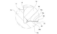
- This example is a modification of the fifth example. Also in this example, the inner diameter side engaging portion 16a is formed on the entire outer peripheral surface of the fitting shaft portion 12c, and the outer diameter side engaging portion 25 is formed on the entire inner peripheral surface of the mounting hole 24b. are doing.
- the engaging portion between the inner diameter side engaging portion 16a and the outer diameter side engaging portion 17a has an interference in the radial direction in a part of the axial direction.
- the root diameter of the male spline teeth 18a forming the inner diameter side engaging portion 16a is not constant throughout the axial direction.
- the diameter of the root circle of the male spline tooth 18a from the end on one side in the axial direction toward the other side in the axial direction is less than the diameter of the tip circle of the female spline tooth 27 that constitutes the outer diameter side engaging portion 25.
- the fitting shaft portion 12c is inserted into the mounting hole 24b, and in a state in which the inner diameter side engaging portion 16a and the outer diameter side engaging portion 25 are spline-engaged, the tooth crest of the female spline tooth 27 A radial interference can be provided between the male spline tooth 18a and the raised portion 49 provided on the tooth bottom portion 48 of the male spline tooth 18a. Therefore, in this example, the end portion on the other axial side of the spline engagement portion between the inner diameter side engaging portion 16a and the outer diameter side engaging portion 25 can have a radial interference.
- the other axial end of the inner diameter engaging portion 16 a can be press-fitted into the other axial end of the outer engaging portion 25 .
- the fitting between the inner diameter side engaging portion 16a and the outer diameter side engaging portion 25 is performed.
- outer diameter surface matching or tooth surface matching can be adopted to ensure a high degree of coaxiality between the screw shaft 2c and the carrier 5c.
- the diameter of the bottom circle of the male spline tooth is constant in the axial direction, and a groove bottom portion of the female spline tooth in the axial direction (for example, one end in the axial direction) is provided with a radially inward groove.
- An overhanging ridge can also be provided.
- both the groove bottom of the male spline tooth and the groove bottom of the female spline tooth may be provided with raised portions.
- the protuberances can be provided on the tooth crests of the male spline teeth and/or the female spline teeth.
- the inner diameter side engaging portion and the outer diameter side engaging portion are not limited to spline teeth, and other structures such as serration teeth may be employed.
- FIG. 13 shows the ball screw device 1 of the seventh example of the embodiment of the present disclosure.
- the entire carrier 5d has a symmetrical shape with respect to the axial direction. For this reason, an outer diameter side engaging portion 25 and a pair of outer diameter side fitting surface portions 26b and 26c are provided on the inner peripheral surface of the mounting hole 24c of the carrier 5d.
- the outer diameter side engaging portion 25 is provided in the axially intermediate portion of the inner peripheral surface of the mounting hole 24c.
- a pair of outer diameter side fitting surface portions 26b and 26c are provided on both sides of the outer diameter side engaging portion 25 in the axial direction of the inner peripheral surface of the mounting hole 24c.
- the directionality in the axial direction can be eliminated for the carrier 5d, so the workability of assembling the carrier 5d to the screw shaft 2 can be improved. Therefore, it is possible to further improve the assemblability of the ball screw device 1 .
- Other configurations and effects are the same as those of the first and second examples.
- male spline teeth are provided on the outer peripheral surface of the fitting shaft portion of the screw shaft, and the inner peripheral surface of the carrier is configured by a mounting hole having female spline teeth, and the carrier is fitted.
- a spline-fitting structure is applied to the shaft coupling portion.
- the fixing structure of the carrier with respect to the fitting shaft portion is not particularly limited.
- the fitting shaft portion has an elliptical cross section and has a width across flat shape (stadium shape) having a pair of flat outer surfaces parallel to each other on the outer peripheral surface
- the mounting hole of the carrier has an elliptical cross section.
Landscapes
- Engineering & Computer Science (AREA)
- General Engineering & Computer Science (AREA)
- Mechanical Engineering (AREA)
- Transportation (AREA)
- Transmission Devices (AREA)
- Mounting Of Bearings Or Others (AREA)
- Rolling Contact Bearings (AREA)
Priority Applications (4)
| Application Number | Priority Date | Filing Date | Title |
|---|---|---|---|
| US18/726,293 US12584544B2 (en) | 2022-01-05 | 2022-12-06 | Ball screw device |
| CN202280076707.3A CN118265858A (zh) | 2022-01-05 | 2022-12-06 | 滚珠丝杠装置 |
| DE112022005579.0T DE112022005579T5 (de) | 2022-01-05 | 2022-12-06 | Kugelgewindetrieb |
| JP2023534322A JP7452766B2 (ja) | 2022-01-05 | 2022-12-06 | ボールねじ装置 |
Applications Claiming Priority (2)
| Application Number | Priority Date | Filing Date | Title |
|---|---|---|---|
| JP2022000587 | 2022-01-05 | ||
| JP2022-000587 | 2022-01-05 |
Publications (1)
| Publication Number | Publication Date |
|---|---|
| WO2023132172A1 true WO2023132172A1 (ja) | 2023-07-13 |
Family
ID=87073488
Family Applications (1)
| Application Number | Title | Priority Date | Filing Date |
|---|---|---|---|
| PCT/JP2022/044845 Ceased WO2023132172A1 (ja) | 2022-01-05 | 2022-12-06 | ボールねじ装置 |
Country Status (5)
| Country | Link |
|---|---|
| US (1) | US12584544B2 (https=) |
| JP (1) | JP7452766B2 (https=) |
| CN (1) | CN118265858A (https=) |
| DE (1) | DE112022005579T5 (https=) |
| WO (1) | WO2023132172A1 (https=) |
Cited By (1)
| Publication number | Priority date | Publication date | Assignee | Title |
|---|---|---|---|---|
| WO2025225314A1 (ja) * | 2024-04-22 | 2025-10-30 | Ntn株式会社 | ボールねじ装置 |
Citations (5)
| Publication number | Priority date | Publication date | Assignee | Title |
|---|---|---|---|---|
| JP2009275914A (ja) * | 2008-04-17 | 2009-11-26 | Smc Corp | 電動アクチュエータ |
| JP2011133073A (ja) * | 2009-12-25 | 2011-07-07 | Ckd Corp | 軸部品 |
| JP2016148374A (ja) * | 2015-02-12 | 2016-08-18 | 本田技研工業株式会社 | 伸縮アクチュエータ |
| JP2018194080A (ja) * | 2017-05-17 | 2018-12-06 | 株式会社エンプラス | 波動歯車装置 |
| US20180345934A1 (en) * | 2015-11-27 | 2018-12-06 | Robert Bosch Gmbh | Piston pump assembly |
Family Cites Families (4)
| Publication number | Priority date | Publication date | Assignee | Title |
|---|---|---|---|---|
| JP4892593B2 (ja) | 2009-09-08 | 2012-03-07 | 日精樹脂工業株式会社 | 電動式竪型型締装置 |
| JP2018079824A (ja) | 2016-11-17 | 2018-05-24 | Ntn株式会社 | 車輪用軸受のスプライン加工方法 |
| JP6873847B2 (ja) * | 2017-07-05 | 2021-05-19 | 株式会社ミツバ | 開閉体駆動装置 |
| JP7800005B2 (ja) * | 2021-07-02 | 2026-01-16 | 株式会社アドヴィックス | 直動アクチュエータ |
-
2022
- 2022-12-06 CN CN202280076707.3A patent/CN118265858A/zh active Pending
- 2022-12-06 DE DE112022005579.0T patent/DE112022005579T5/de active Pending
- 2022-12-06 JP JP2023534322A patent/JP7452766B2/ja active Active
- 2022-12-06 WO PCT/JP2022/044845 patent/WO2023132172A1/ja not_active Ceased
- 2022-12-06 US US18/726,293 patent/US12584544B2/en active Active
Patent Citations (5)
| Publication number | Priority date | Publication date | Assignee | Title |
|---|---|---|---|---|
| JP2009275914A (ja) * | 2008-04-17 | 2009-11-26 | Smc Corp | 電動アクチュエータ |
| JP2011133073A (ja) * | 2009-12-25 | 2011-07-07 | Ckd Corp | 軸部品 |
| JP2016148374A (ja) * | 2015-02-12 | 2016-08-18 | 本田技研工業株式会社 | 伸縮アクチュエータ |
| US20180345934A1 (en) * | 2015-11-27 | 2018-12-06 | Robert Bosch Gmbh | Piston pump assembly |
| JP2018194080A (ja) * | 2017-05-17 | 2018-12-06 | 株式会社エンプラス | 波動歯車装置 |
Cited By (1)
| Publication number | Priority date | Publication date | Assignee | Title |
|---|---|---|---|---|
| WO2025225314A1 (ja) * | 2024-04-22 | 2025-10-30 | Ntn株式会社 | ボールねじ装置 |
Also Published As
| Publication number | Publication date |
|---|---|
| DE112022005579T5 (de) | 2024-09-12 |
| US12584544B2 (en) | 2026-03-24 |
| JPWO2023132172A1 (https=) | 2023-07-13 |
| US20250075778A1 (en) | 2025-03-06 |
| CN118265858A (zh) | 2024-06-28 |
| JP7452766B2 (ja) | 2024-03-19 |
Similar Documents
| Publication | Publication Date | Title |
|---|---|---|
| JP7276629B1 (ja) | ボールねじ装置およびその製造方法 | |
| JP7338810B1 (ja) | ボールねじ装置およびねじ軸の製造方法 | |
| JP7452766B2 (ja) | ボールねじ装置 | |
| JP2022189061A (ja) | ボールねじ装置 | |
| US11867264B2 (en) | Ball screw device and method for manufacturing same | |
| US11655886B1 (en) | Ball screw device | |
| JP6520056B2 (ja) | 無段変速装置 | |
| JP2024021633A (ja) | ボールねじ装置 | |
| JP7473091B2 (ja) | ボールねじ装置およびその製造方法 | |
| JP7226674B1 (ja) | ボールねじ装置 | |
| CN117795227A (zh) | 滚珠丝杠装置及其制造方法 | |
| JP2022189062A (ja) | ボールねじ装置 | |
| JP2024058020A (ja) | ボールねじ装置 | |
| WO2024135483A1 (ja) | アクチュエータ | |
| JP2022166703A (ja) | ボールねじ装置 | |
| JP2023079625A (ja) | クラッチアクチュエータ |
Legal Events
| Date | Code | Title | Description |
|---|---|---|---|
| WWE | Wipo information: entry into national phase |
Ref document number: 2023534322 Country of ref document: JP |
|
| 121 | Ep: the epo has been informed by wipo that ep was designated in this application |
Ref document number: 22918759 Country of ref document: EP Kind code of ref document: A1 |
|
| WWE | Wipo information: entry into national phase |
Ref document number: 202280076707.3 Country of ref document: CN |
|
| WWE | Wipo information: entry into national phase |
Ref document number: 18726293 Country of ref document: US |
|
| 122 | Ep: pct application non-entry in european phase |
Ref document number: 22918759 Country of ref document: EP Kind code of ref document: A1 |
|
| WWP | Wipo information: published in national office |
Ref document number: 18726293 Country of ref document: US |
|
| WWG | Wipo information: grant in national office |
Ref document number: 18726293 Country of ref document: US |