WO2023119601A1 - ヒータ - Google Patents
ヒータ Download PDFInfo
- Publication number
- WO2023119601A1 WO2023119601A1 PCT/JP2021/048052 JP2021048052W WO2023119601A1 WO 2023119601 A1 WO2023119601 A1 WO 2023119601A1 JP 2021048052 W JP2021048052 W JP 2021048052W WO 2023119601 A1 WO2023119601 A1 WO 2023119601A1
- Authority
- WO
- WIPO (PCT)
- Prior art keywords
- flow path
- heating element
- heater
- substrate
- frequency electrode
- Prior art date
- Legal status (The legal status is an assumption and is not a legal conclusion. Google has not performed a legal analysis and makes no representation as to the accuracy of the status listed.)
- Ceased
Links
Images





Classifications
-
- H—ELECTRICITY
- H10—SEMICONDUCTOR DEVICES; ELECTRIC SOLID-STATE DEVICES NOT OTHERWISE PROVIDED FOR
- H10P—GENERIC PROCESSES OR APPARATUS FOR THE MANUFACTURE OR TREATMENT OF DEVICES COVERED BY CLASS H10
- H10P72/00—Handling or holding of wafers, substrates or devices during manufacture or treatment thereof
- H10P72/70—Handling or holding of wafers, substrates or devices during manufacture or treatment thereof for supporting or gripping
- H10P72/78—Handling or holding of wafers, substrates or devices during manufacture or treatment thereof for supporting or gripping using vacuum or suction, e.g. Bernoulli chucks
-
- H—ELECTRICITY
- H05—ELECTRIC TECHNIQUES NOT OTHERWISE PROVIDED FOR
- H05B—ELECTRIC HEATING; ELECTRIC LIGHT SOURCES NOT OTHERWISE PROVIDED FOR; CIRCUIT ARRANGEMENTS FOR ELECTRIC LIGHT SOURCES, IN GENERAL
- H05B3/00—Ohmic-resistance heating
- H05B3/20—Heating elements having extended surface area substantially in a two-dimensional [2D] plane, e.g. plate-heater
- H05B3/22—Heating elements having extended surface area substantially in a two-dimensional [2D] plane, e.g. plate-heater non-flexible
- H05B3/28—Heating elements having extended surface area substantially in a two-dimensional [2D] plane, e.g. plate-heater non-flexible heating conductor embedded in insulating material
- H05B3/283—Heating elements having extended surface area substantially in a two-dimensional [2D] plane, e.g. plate-heater non-flexible heating conductor embedded in insulating material the insulating material being an inorganic material, e.g. ceramic
-
- C—CHEMISTRY; METALLURGY
- C23—COATING METALLIC MATERIAL; COATING MATERIAL WITH METALLIC MATERIAL; CHEMICAL SURFACE TREATMENT; DIFFUSION TREATMENT OF METALLIC MATERIAL; COATING BY VACUUM EVAPORATION, BY SPUTTERING, BY ION IMPLANTATION OR BY CHEMICAL VAPOUR DEPOSITION, IN GENERAL; INHIBITING CORROSION OF METALLIC MATERIAL OR INCRUSTATION IN GENERAL
- C23C—COATING METALLIC MATERIAL; COATING MATERIAL WITH METALLIC MATERIAL; SURFACE TREATMENT OF METALLIC MATERIAL BY DIFFUSION INTO THE SURFACE, BY CHEMICAL CONVERSION OR SUBSTITUTION; COATING BY VACUUM EVAPORATION, BY SPUTTERING, BY ION IMPLANTATION OR BY CHEMICAL VAPOUR DEPOSITION, IN GENERAL
- C23C16/00—Chemical coating by decomposition of gaseous compounds, without leaving reaction products of surface material in the coating, i.e. chemical vapour deposition [CVD] processes
- C23C16/44—Chemical coating by decomposition of gaseous compounds, without leaving reaction products of surface material in the coating, i.e. chemical vapour deposition [CVD] processes characterised by the method of coating
- C23C16/458—Chemical coating by decomposition of gaseous compounds, without leaving reaction products of surface material in the coating, i.e. chemical vapour deposition [CVD] processes characterised by the method of coating characterised by the method used for supporting substrates in the reaction chamber
- C23C16/4582—Rigid and flat substrates, e.g. plates or discs
- C23C16/4583—Rigid and flat substrates, e.g. plates or discs the substrate being supported substantially horizontally
- C23C16/4586—Elements in the interior of the support, e.g. electrodes, heating or cooling devices
-
- C—CHEMISTRY; METALLURGY
- C23—COATING METALLIC MATERIAL; COATING MATERIAL WITH METALLIC MATERIAL; CHEMICAL SURFACE TREATMENT; DIFFUSION TREATMENT OF METALLIC MATERIAL; COATING BY VACUUM EVAPORATION, BY SPUTTERING, BY ION IMPLANTATION OR BY CHEMICAL VAPOUR DEPOSITION, IN GENERAL; INHIBITING CORROSION OF METALLIC MATERIAL OR INCRUSTATION IN GENERAL
- C23C—COATING METALLIC MATERIAL; COATING MATERIAL WITH METALLIC MATERIAL; SURFACE TREATMENT OF METALLIC MATERIAL BY DIFFUSION INTO THE SURFACE, BY CHEMICAL CONVERSION OR SUBSTITUTION; COATING BY VACUUM EVAPORATION, BY SPUTTERING, BY ION IMPLANTATION OR BY CHEMICAL VAPOUR DEPOSITION, IN GENERAL
- C23C16/00—Chemical coating by decomposition of gaseous compounds, without leaving reaction products of surface material in the coating, i.e. chemical vapour deposition [CVD] processes
- C23C16/44—Chemical coating by decomposition of gaseous compounds, without leaving reaction products of surface material in the coating, i.e. chemical vapour deposition [CVD] processes characterised by the method of coating
- C23C16/46—Chemical coating by decomposition of gaseous compounds, without leaving reaction products of surface material in the coating, i.e. chemical vapour deposition [CVD] processes characterised by the method of coating characterised by the method used for heating the substrate
-
- H—ELECTRICITY
- H01—ELECTRIC ELEMENTS
- H01J—ELECTRIC DISCHARGE TUBES OR DISCHARGE LAMPS
- H01J37/00—Discharge tubes with provision for introducing objects or material to be exposed to the discharge, e.g. for the purpose of examination or processing thereof
- H01J37/32—Gas-filled discharge tubes
- H01J37/32431—Constructional details of the reactor
- H01J37/32532—Electrodes
- H01J37/32568—Relative arrangement or disposition of electrodes; moving means
-
- H—ELECTRICITY
- H01—ELECTRIC ELEMENTS
- H01J—ELECTRIC DISCHARGE TUBES OR DISCHARGE LAMPS
- H01J37/00—Discharge tubes with provision for introducing objects or material to be exposed to the discharge, e.g. for the purpose of examination or processing thereof
- H01J37/32—Gas-filled discharge tubes
- H01J37/32431—Constructional details of the reactor
- H01J37/32715—Workpiece holder
-
- H—ELECTRICITY
- H10—SEMICONDUCTOR DEVICES; ELECTRIC SOLID-STATE DEVICES NOT OTHERWISE PROVIDED FOR
- H10P—GENERIC PROCESSES OR APPARATUS FOR THE MANUFACTURE OR TREATMENT OF DEVICES COVERED BY CLASS H10
- H10P14/00—Formation of materials, e.g. in the shape of layers or pillars
- H10P14/60—Formation of materials, e.g. in the shape of layers or pillars of insulating materials
-
- H—ELECTRICITY
- H10—SEMICONDUCTOR DEVICES; ELECTRIC SOLID-STATE DEVICES NOT OTHERWISE PROVIDED FOR
- H10P—GENERIC PROCESSES OR APPARATUS FOR THE MANUFACTURE OR TREATMENT OF DEVICES COVERED BY CLASS H10
- H10P72/00—Handling or holding of wafers, substrates or devices during manufacture or treatment thereof
- H10P72/04—Apparatus for manufacture or treatment
- H10P72/0431—Apparatus for thermal treatment
- H10P72/0432—Apparatus for thermal treatment mainly by conduction
-
- H—ELECTRICITY
- H10—SEMICONDUCTOR DEVICES; ELECTRIC SOLID-STATE DEVICES NOT OTHERWISE PROVIDED FOR
- H10P—GENERIC PROCESSES OR APPARATUS FOR THE MANUFACTURE OR TREATMENT OF DEVICES COVERED BY CLASS H10
- H10P72/00—Handling or holding of wafers, substrates or devices during manufacture or treatment thereof
- H10P72/70—Handling or holding of wafers, substrates or devices during manufacture or treatment thereof for supporting or gripping
-
- H—ELECTRICITY
- H10—SEMICONDUCTOR DEVICES; ELECTRIC SOLID-STATE DEVICES NOT OTHERWISE PROVIDED FOR
- H10P—GENERIC PROCESSES OR APPARATUS FOR THE MANUFACTURE OR TREATMENT OF DEVICES COVERED BY CLASS H10
- H10P72/00—Handling or holding of wafers, substrates or devices during manufacture or treatment thereof
- H10P72/70—Handling or holding of wafers, substrates or devices during manufacture or treatment thereof for supporting or gripping
- H10P72/76—Handling or holding of wafers, substrates or devices during manufacture or treatment thereof for supporting or gripping using mechanical means, e.g. clamps or pinches
- H10P72/7604—Handling or holding of wafers, substrates or devices during manufacture or treatment thereof for supporting or gripping using mechanical means, e.g. clamps or pinches the wafers being placed on a susceptor, stage or support
- H10P72/7624—Handling or holding of wafers, substrates or devices during manufacture or treatment thereof for supporting or gripping using mechanical means, e.g. clamps or pinches the wafers being placed on a susceptor, stage or support characterised by the mechanical construction of the susceptor, stage or support
Definitions
- the present disclosure relates to heaters.
- Patent Document 1 discloses a ceramic member in which an RF plate and a heater plate are connected with a space interposed therebetween.
- the RF plate has a mounting surface on which a wafer, which is an object to be heated, is mounted.
- a high-frequency electrode used when performing plasma processing on the wafer is arranged inside the RF plate.
- a heating resistor is arranged inside the heater plate. The space is provided to suppress generation of leak current flowing between the high-frequency electrode and the heating resistor.
- the heater of the present disclosure is a substrate having a disk-like shape; a high-frequency electrode disposed inside the base; a heating element disposed inside the base; a support having a tubular shape;
- the substrate is a first surface on which an object to be heated is placed; a second surface to which the first end of the support is attached; a flow path connected to the first surface and the second surface;
- the flow path is a first flow path having an intake port provided on the first surface side; a second flow path having an exhaust port provided in a region inside the support on the second surface side; a third flow path that connects the first flow path and the second flow path,
- Each of the high-frequency electrode, the heating element, and the third flow path is arranged in a plane parallel to the first plane, The heating element and the third channel are arranged closer to the second surface than the high-frequency electrode.
- FIG. 1 is a cross-sectional view schematically showing a film forming apparatus equipped with a heater according to Embodiment 1.
- FIG. FIG. 2 is a cross-sectional view mainly showing an enlarged substrate of the heater shown in FIG.
- FIG. 3 is a cross-sectional view taken along line III-III of FIG.
- FIG. 4 is a cross-sectional view of a third flow path in modification 1.
- FIG. 5 is a cross-sectional view of a third flow path in modification 2.
- FIG. FIG. 6 is a cross-sectional view of a third flow path in modification 3.
- FIG. FIG. 7 is a cross-sectional view of a third flow path in modification 4.
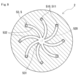
- FIG. FIG. 8 is a cross-sectional view of a third flow path in modification 5.
- FIG. FIG. FIG. 1 is a cross-sectional view schematically showing a film forming apparatus equipped with a heater according to Embodiment 1.
- FIG. FIG. 2 is a cross-sectional view mainly
- FIG. 9 is a cross-sectional view of a third flow path in modification 6.
- FIG. FIG. 10 is a sectional view mainly showing an enlarged substrate of the heater of Embodiment 2.
- FIG. 11 is a cross-sectional view mainly showing an enlarged substrate of the heater of Embodiment 3.
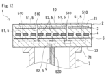
- FIG. 12 is a sectional view mainly showing an enlarged substrate of the heater of Embodiment 4.
- FIG. 13 is a cross-sectional view mainly showing an enlarged substrate of the heater of the fifth embodiment.
- Patent Document 1 has room for improvement in terms of uniformly heating the object to be heated and uniformly forming a film on the object to be heated.
- One object of the present disclosure is to provide a heater that can uniformly heat the entire surface of a heating target and that can suppress variations in film formation on the heating target.
- the heater of the present disclosure can uniformly heat the entire surface of the object to be heated, and can suppress variations in film formation on the object to be heated.
- a heater a substrate having a disk-like shape; a high-frequency electrode disposed inside the base; a heating element disposed inside the base; a support having a tubular shape;
- the substrate is a first surface on which an object to be heated is placed; a second surface to which the first end of the support is attached; a flow path connected to the first surface and the second surface;
- the flow path is a first flow path having an intake port provided on the first surface side; a second flow path having an exhaust port provided in a region inside the support on the second surface side; a third flow path that connects the first flow path and the second flow path,
- Each of the high-frequency electrode, the heating element, and the third flow path is arranged in a plane parallel to the first plane, The heating element and the third channel are arranged closer to the second surface than the high-frequency electrode.
- the object to be heated placed on the first surface is vacuum-adsorbed to the first surface by the channel provided in the base. This vacuum suction corrects the warpage even in the case of a plate-like object warped before the object to be heated is placed on the first surface.
- the object to be heated placed on the first surface can contact the first surface over the entire surface.
- the heating element is arranged in a plane parallel to the first plane. Therefore, in the heater of the present disclosure, the object to be heated placed on the first surface is uniformly heated over the entire surface by the heating element.
- the heating element and the third flow path are located closer to the second surface than the high-frequency electrode. In other words, neither the heating element nor the third channel exists between the high-frequency electrode and the first surface.
- the high frequency electrode is arranged in a plane parallel to the first plane. Since the heating element and the third flow path are not present between the high-frequency electrode and the first surface, the thickness of the substrate between the object to be heated placed on the first surface and the high-frequency electrode is ensured to be uniform. easy. Since the third flow path does not exist between the high-frequency electrode and the first surface, it is possible to suppress the occurrence of electric discharge between the object to be heated and the high-frequency electrode, thereby suppressing the occurrence of energy loss.
- a shower head that generates reactive gas used in plasma processing also serves as a high-frequency electrode paired with the high-frequency electrode, and is arranged parallel to the first surface. Since the object to be heated contacts the first surface over the entire surface, it is easy to ensure a uniform gap between the object to be heated placed on the first surface and the showerhead.
- the thickness of the substrate between the object to be heated placed on the first surface and the high-frequency electrode is ensured to be uniform, and the object to be heated placed on the first surface and the shower head By securing a uniform interval, energy is applied uniformly over the entire surface of the object to be heated. Therefore, in the heater of the present disclosure, variations in film formation on the object to be heated by plasma processing are suppressed as compared to the case where the thickness of the substrate or the spacing is non-uniform.
- the third flow path may be arranged closer to the second surface than the heating element.
- heat transfer from the heating element to the first surface is less likely to be hindered by the third flow path. Therefore, in the above embodiment, the object to be heated placed on the first surface is heated more uniformly over the entire surface by the heating element.
- the distance between the high-frequency electrode and the third channel in the thickness direction of the base may be 2 mm or more.
- the heater of the present disclosure further includes a shield electrode disposed inside the base, wherein the shield electrode is positioned in a plane parallel to the first plane, and the high-frequency electrode and the third flow path may be arranged in the plane between
- provision of the shield electrode suppresses application of energy to the third flow path.
- it since it is difficult to apply energy to the third flow path, it is easy to suppress the occurrence of electric discharge in the space forming the third flow path during film formation on the object to be heated by plasma processing.
- the number of the first flow paths may be plural, and the intake ports may be arranged side by side in the circumferential direction of the base on the first surface.
- the object to be heated placed on the first surface is vacuum-sucked to the first surface over the entire circumference.
- the number of the first flow paths is plural, the number of the second flow paths is one, and the first surface has a plurality of first air inlets as the air inlets. is provided, and lengths along the first flow path, the second flow path, and the third flow path from each of the plurality of first intake ports to the exhaust port may be the same .
- the object to be heated placed on the first surface is vacuum-sucked to the first surface by the plurality of first air inlets having the same suction force.
- the object to be heated placed on the first surface is uniformly vacuum-adsorbed to the first surface over the entire circumference.
- the number of the first flow paths is plural, the number of the second flow paths is one, and the first surface includes a second air inlet and a second air inlet as the air inlets. Three inlets are provided, and lengths along the first flow path, the second flow path, and the third flow path from each of the second intake port and the third intake port to the exhaust port may differ.
- the object to be heated placed on the first surface is vacuum-sucked to the first surface at different positions in the radial direction of the substrate.
- the number of the first flow paths is plural, the third flow paths are provided with a plurality of branch paths extending radially from the center side of the substrate, and one or a plurality of the first flow paths are provided.
- the second channel may be connected to the center side of the substrate in the third channel, and at least one of the plurality of first channels may be connected to the tip of the branched channel.
- the object to be heated placed on the first surface is uniformly vacuum-sucked to the first surface over the entire circumference.
- FIG. 1 A heater 1 according to an embodiment will be described with reference to FIGS. 1 to 3.
- FIG. The heater 1 is used in a film forming apparatus that forms a thin film on the surface of a heating target 10 by plasma processing.
- the heater 1, as shown in FIG. 1, is placed in a chamber 8 in which the ambient gas can be controlled.
- a shower head 81 is arranged on the upper surface facing the heater 1 in the chamber 8 .
- a reactive gas used in plasma processing is jetted from the showerhead 81 toward the heater 1 .
- a high-frequency oscillator (not shown) is connected to the shower head 81 .
- the shower head 81 also serves as a high frequency electrode.
- the heater 1 includes a substrate 2, a high frequency electrode 3, a heating element 4, and a support 7, as shown in FIGS.
- the heater 1 may further comprise a shield electrode 6 as shown in FIGS. 11-13.
- the high-frequency electrode 3, the heating element 4, and the shield electrode 6 are arranged inside the base 2 so as to be parallel to each other.
- the substrate 2 is provided with the flow path 5 as a configuration for vacuum-sucking the heating target 10 to the substrate 2 .
- the high-frequency electrode 3, the heating element 4, and the flow path 5 are arranged inside the substrate 2 in a specific order. If the heater 1 comprises shield electrodes 6, the shield electrodes 6 are also arranged inside the substrate 2 in a particular order.
- FIG. 1 to 3 illustrate the heater 1 of Embodiment 1.
- FIG. 4 to 9 illustrate different patterns of third channels 53 provided in the substrate 2 of the heater 1.
- FIG. Third channel 53 is part of channel 5 .
- FIG. 10 illustrates the heater 1 of the second embodiment. 10, the order of the heating element 4 and the third flow path 53 shown in FIG. 2 is reversed.
- FIG. 11 illustrates the heater 1 of Embodiment 3.
- FIG. 11 adds a shield electrode 6 to the substrate 2 shown in FIG.
- FIG. 12 illustrates the heater 1 of Embodiment 4.
- FIG. FIG. 12 adds a shield electrode 6 to the substrate 2 shown in FIG.
- FIG. 13 illustrates the heater 1 of embodiment 5.
- FIG. In FIG. 13, a shield electrode 6 is added to the substrate 2 shown in FIG.
- the high-frequency electrode 3, the heating element 4, the flow path 5, and the shield electrode 6 are exaggerated for easy understanding.
- the sizes of the substrate 2, the high-frequency electrode 3, the heating element 4, the flow path 5, the shield electrode 6, etc. are shown schematically, and do not necessarily correspond to the actual sizes. do not have.
- each configuration will be described in detail for each embodiment.
- FIG. 1 The heater 1 of Embodiment 1 will be described with reference to FIGS. 1 to 3.
- FIG. The heater 1 of Embodiment 1 includes a substrate 2, a high-frequency electrode 3, a heating element 4, and a support 7, as shown in FIGS.
- the high-frequency electrode 3, the third flow path 53 which is a part of the flow path 5, and the heating element are arranged in order from the first surface 21 side to the second surface 22 side inside the base 2. 4 are placed.
- the substrate 2 has a disk-like shape, as shown in FIG.
- the base 2 has a first surface 21 and a second surface 22, as shown in FIG.
- the first surface 21 and the second surface 22 face each other.
- a heating target 10 is placed on the first surface 21 .
- the object 10 to be heated is, for example, a silicon or compound semiconductor wafer.
- a first end portion 71 of the support 7 described later is attached to the second surface 22 .
- a plurality of holes in which terminals (not shown) connected to the high-frequency electrode 3 and the heating element 4 (to be described later) are fitted are provided in the inner region of the support 7 on the second surface 22 side.
- the terminals protrude from the second surface 22 .
- the terminals and the plurality of holes in which the terminals are fitted are not shown.
- the channel 5 is provided so as to connect the first surface 21 and the second surface 22 .
- the material of the substrate 2 is, for example, known ceramics. Ceramics are, for example, aluminum nitride, aluminum oxide, and silicon carbide.
- the material of the substrate 2 may be composed of a composite material of the above ceramics and metal. Metals are, for example, aluminum, aluminum alloys, copper, copper alloys.
- the material of the substrate 2 in this example is aluminum nitride.
- the high frequency electrode 3 is an electrode that generates plasma with the shower head 81 shown in FIG.
- the high frequency electrode 3 is grounded.
- the high-frequency electrode 3 is connected to a high-frequency oscillator different from the high-frequency oscillator connected to the showerhead 81 .
- the high frequency electrode 3 is connected to a power line (not shown). Power lines include ground lines. The power line is arranged inside a support 7, which will be described later.
- High-frequency power is supplied between the showerhead 81 and the high-frequency electrode 3 from a high-frequency oscillator (not shown).
- the reactive gas jetted from the showerhead 81 is ionized by high frequency energy to generate a plasma state.
- a chemical reaction occurs in the object to be heated 10 placed on the first surface 21 according to the plasma state of the reaction gas, and a thin film is formed on the object to be heated 10 according to the reaction gas.
- the high-frequency electrode 3 has a disk-like shape.
- the high-frequency electrode 3 is preferably arranged concentrically with the substrate 2 .
- the high-frequency electrode 3 has, for example, the same size as the object 10 to be heated.
- the high-frequency electrode 3 may be one size larger than the object 10 to be heated.
- the high frequency electrode 3 is embedded inside the base 2 .
- the high frequency electrode 3 is arranged in a plane parallel to the first plane 21 .
- the high-frequency electrode 3 is positioned closest to the first surface 21 in the thickness direction of the substrate 2 . Between the high-frequency electrode 3 and the first surface 21, the heating element 4 and the third channel 53, which will be described later, do not exist.
- a distance D1 between the high-frequency electrode 3 and the first surface 21 is, for example, about 1 mm.
- the material of the high-frequency electrode 3 is metal with excellent heat resistance.
- the metal is, for example, one selected from the group consisting of tungsten, tungsten alloys, molybdenum, molybdenum alloys, nickel, and nickel alloys.
- the form of the high-frequency electrode 3 is not particularly limited.
- the high-frequency electrode 3 is formed by screen-printing and firing a paste containing powder made of the above metal.
- the high frequency electrode 3 may consist of a plate, mesh or fabric.
- the heating element 4 is a heat source that heats the heating target 10 placed on the first surface 21 .
- the heating element 4 heats the object to be heated 10 via the base 2 .
- the heating element 4 is connected to terminals and power lines (not shown).
- the power line is arranged inside a support 7, which will be described later. Electric power is supplied to the heating element 4 from a power supply (not shown) through a power line.
- the heating element 4 is a circuit pattern formed within the plane of the substrate 2 .
- the circuit pattern is drawn with strips made up of strip-like thin lines.
- the shape of the heating element 4 is not particularly limited. When the substrate 2 is viewed from the first surface 21 side, the shape of the outer peripheral contour of the heating element 4 is generally circular. The outline of the outer periphery of the heating element 4 is formed by the arrangement of the band-shaped portions.
- the heating element 4 is preferably arranged concentrically with the substrate 2 .
- the heating element 4 is also arranged concentrically with the high-frequency electrode 3 .
- the heating element 4 is embedded inside the base 2 .
- the heating element 4 is arranged in a plane parallel to the first surface 21 .
- the heating element 4 is arranged closer to the second surface 22 than the high-frequency electrode 3 is.
- the heating element 4 is configured by, for example, bending a belt-like portion.
- the bending of the belt-like portion includes bending in a spiral shape and a meandering shape.
- the heating element 4 may have a planar portion of a predetermined shape that is wider than the belt-like portion.
- the shape of the outer peripheral contour line of the planar portion is, for example, fan-shaped or semi-circular.
- the band-like portion and the planar portion are connected in series.
- the circuit pattern of the heating element 4 is not particularly limited. The circuit pattern of the heating element 4 can be appropriately selected according to the heating temperature and the required temperature distribution.
- the material of the heating element 4 is not particularly limited as long as it can heat the heating target 10 to a desired temperature.
- the material of the heating element 4 is a metal suitable for resistance heating.
- the metal is, for example, one selected from the group consisting of stainless steel, nickel, nickel alloys, silver, silver alloys, tungsten, tungsten alloys, molybdenum, molybdenum alloys, chromium, and chromium alloys.
- a nickel alloy is, for example, nichrome.
- the form of the heating element 4 is not particularly limited.
- the heating element 4 is formed by screen-printing and firing a paste containing powder made of the above metal.
- the heating element 4 is formed by patterning a foil made of the above metal.
- the heating element 4 may be a tungsten coil or a molybdenum coil other than the circuit pattern of the belt-like portion.
- the channel 5 is a space provided inside the base 2 .
- the channel 5 is provided so as to be connected to the first surface 21 and the second surface 22, as shown in FIG.
- the channel 5 includes a first channel 51 , a second channel 52 and a third channel 53 .
- the outer shape including the third flow path 53 is indicated by a chain double-dashed line.
- FIG. 3 is a cross-sectional view of the third flow path 53 shown in FIG. 2 taken along a plane parallel to the first surface 21 .
- the intake port 510 provided on the first surface 21 side is indicated by a solid line.
- the exhaust port 520 provided on the second surface 22 side is virtually indicated by a dashed line.
- the first flow path 51 has an air inlet 510 provided on the first surface 21 side.
- the intake port 510 of this example is provided on the first surface 21 .
- the bottom surface of the wafer pocket is the first surface 21 and the first surface 21 is provided with the air inlet 510 .
- grooves are provided on the first surface 21, a plurality of air inlets 510 may be provided on the bottom surface of the grooves.
- the channel 5 of this example includes a plurality of first channels 51 .
- a plurality of intake ports 510 are arranged on the first surface 21 shown in FIG. 2, as shown in FIG. Each intake port 510 is covered with the heating target 10 placed on the first surface 21 .
- the plurality of air inlets 510 are preferably arranged side by side in the circumferential direction of the base 2 on the first surface 21 . In particular, it is preferable that the plurality of air inlets 510 be arranged at regular intervals in the circumferential direction of the base 2 on the first surface 21 (FIG. 2).
- a plurality of air inlets 510 may be arranged on each circumference of different diameters of the substrate 2 on the first surface (FIG. 2). In this example, four intake ports 510 are arranged on each circumference of two different diameters of the substrate 2 .
- the opening shape of the intake port 510 is not particularly limited.
- the opening shape of the intake port 510 of this example is circular.
- the first flow path 51 extends from each intake port 510 toward the interior of the base 2 .
- the first channel 51 extends in a direction intersecting the first surface 21 .
- the first flow path 51 of this example extends in a direction orthogonal to the first surface 21 .
- the cross-sectional shape of the first flow path 51 is not particularly limited.
- the shape of the cross section of the first flow path 51 of this example is circular, which is the same as the opening shape of the intake port 510 .
- a cross section of the first flow path 51 is a cross section cut in a direction perpendicular to the direction in which the first flow path 51 extends.
- the cross-sectional area of the first flow path 51 can be appropriately selected to the extent that good gas flowability can be ensured.
- the gas is, for example, a reaction gas.
- the total cross-sectional area of the first flow path 51 is, for example, 0.2 mm 2 or more and 2500 mm 2 or less, preferably 15 mm 2 or more and 500 mm 2 or less.
- Favorable gas flowability is ensured because the total cross-sectional area of the first flow path 51 is equal to or greater than the lower limit. Since the total cross-sectional area of the first flow path 51 is equal to or less than the upper limit value, it is easy to suppress the heat transfer from the heating element 4 from being blocked in the first flow path 51 .
- the cross-sectional area of each first flow path 51 is appropriately selected so that the total cross-sectional area of the plurality of cross-sections satisfies the above range.
- the first flow path 51 of this example has a uniform cross-sectional shape and size in the direction in which the first flow path 51 extends.
- the cross-sectional shape of the first flow path 51 may change in the middle of the extending direction of the first flow path 51 .
- the cross-sectional area of the first flow path 51 may change in the middle of the direction in which the first flow path 51 extends.
- each first flow path 51 may be the same or different.
- the first flow path 51 is provided on the first surface 21 so that the intake ports 510 are arranged on the circumferences of the substrate 2 with different diameters, the first flow path 51 positioned on the small diameter side and the first flow path 51 positioned on the large diameter side.
- the second flow path 52 includes an exhaust port 520 provided in a region inside the support 7 on the second surface 22, as shown in FIG.
- the exhaust port 520 of this example is provided on the second surface 22 .
- an exhaust port 520 is provided on the end surface of the convex portion or the bottom surface of the concave portion.
- a suction pipe 9 is connected to the exhaust port 520 .
- a vacuum pump (not shown) is connected to the suction pipe 9 .
- the inside of the flow path 5 is decompressed through the suction pipe 9 by the suction of the vacuum pump.
- the suction tube 9 is arranged inside a support 7, which will be described later.
- the channel 5 of this example includes one second channel 52 .
- one exhaust port 520 is arranged on the second surface 22 shown in FIG.
- the exhaust port 520 is preferably arranged on the center side of the base 2 on the second surface 22 .
- the exhaust port 520 of this example is provided concentrically with the center of the base 2 .
- the opening shape of the exhaust port 520 is not particularly limited.
- the opening shape of the exhaust port 520 in this example is circular.
- the second flow path 52 extends from the exhaust port 520 toward the interior of the base 2 .
- the second flow path 52 extends in a direction intersecting the second surface 22 .
- the second flow path 52 of this example extends in a direction orthogonal to the second surface 22 .
- the extending direction of the first channel 51 and the extending direction of the second channel 52 are parallel to each other and parallel to the axial direction of the substrate 2 .
- the cross-sectional shape of the second flow path 52 is not particularly limited.
- the shape of the cross section of the second flow path 52 of this example is the same circular shape as the opening shape of the exhaust port 520 .
- the cross section of the second flow path 52 is a cross section cut in a direction orthogonal to the extending direction of the second flow path 52 .
- the cross-sectional area of the second flow path 52 can be appropriately selected to the extent that good gas flowability can be ensured.
- the cross-sectional area of the second flow path 52 is 0.2 mm 2 or more and 50 mm 2 or less, preferably 2 mm 2 or more and 20 mm 2 or less.
- the area of the cross section of the second flow path 52 is equal to or more than the lower limit value, good gas flowability is ensured. Since the area of the cross section of the second channel 52 is equal to or less than the upper limit, even if the heating element 4 is arranged closer to the second surface 22 than the third channel 53, the arrangement of the heating element 4 and Heat transfer is less likely to be hindered.
- the second flow path 52 of this example has a uniform cross-sectional shape and size in the direction in which the second flow path 52 extends.
- the cross-sectional shape of the second flow path 52 may change in the middle of the extending direction of the second flow path 52 .
- the cross-sectional area of the second flow path 52 may change in the middle of the extending direction of the second flow path 52 .
- the third flow path 53 connects the first flow path 51 and the second flow path 52, as shown in FIG.
- the third flow path 53 is arranged in a plane parallel to the first surface 21 .
- the third flow path 53 extends along a plane parallel to the first plane 21 .
- the third flow path 53 is arranged closer to the second surface 22 than the high-frequency electrode 3 is.
- a distance D2 in the thickness direction of the substrate 2 between the high-frequency electrode 3 and the third channel 53 is, for example, 2 mm or more. When the distance D2 is 2 mm or more, it is easy to suppress the occurrence of discharge in the space forming the third flow path 53 when the film is formed on the object 10 to be heated by plasma processing.
- the interval D2 is, for example, 12 mm or less. When the distance D2 is 12 mm or less, the thickness of the substrate 2 is easily suppressed.
- the distance D2 is, for example, 2 mm or more and 12 mm or less, and further 4 mm or more and 8 mm or less
- the third flow path 53 of this example is arranged closer to the first surface 21 than the heating element 4 is. That is, the third flow path 53 of this example is arranged in the plane between the high-frequency electrode 3 and the heating element 4 .
- a distance D3 in the thickness direction of the substrate 2 between the heating element 4 and the third flow path 53 is, for example, 2 mm or more. When the distance D3 is 2 mm or more, the thickness of the substrate 2 between the heating element 4 and the third flow path 53 can be secured to some extent, and heat transfer from the heating element 4 via the substrate 2 can be secured. easy.
- the interval D3 is, for example, 12 mm or less. When D3 is 12 mm or less, thickening of the substrate 2 is easily suppressed.
- the distance D3 is, for example, 2 mm or more and 12 mm or less, and further 4 mm or more and 8 mm or less.
- the third channel 53 preferably has a central portion 531 and a plurality of branch channels 532, as shown in FIG.
- the third flow path 53 of this example further includes a circular path 533 that connects midway points in the extending direction of the branch paths 532 .
- a second intake port 512 and a third intake port 513 are provided as the intake port 510 .
- the central portion 531 is arranged substantially at the center of the base 2 .
- the second channel 52 shown in FIG. 2 is connected to the central portion 531 . That is, the exhaust port 520 is arranged substantially at the center of the base body 2 .
- Each branch path 532 is arranged so as to radially extend from the central portion 531 .
- Each branch 532 has the same length.
- the length of each branch path 532 is a length that reaches the peripheral edge of the object 10 to be heated.
- four branch paths 532 are arranged.
- the four branch paths 532 are arranged so as to line up at regular intervals in the circumferential direction of the base body 2 .
- the first flow path 51 shown in FIG. 2 is connected to the tip of each branched path 532 . By connecting the first flow path 51 to each tip of the plurality of branched paths 532, the first surface 21 shown in FIG. ing.
- the plurality of second air inlets 512 are arranged side by side on a single-diameter circumference of the base body 2 on the first surface 21 .
- the lengths along the first channel 51, the second channel 52, and the third channel 53 from each second intake port 512 to the exhaust port 520 are the same.
- the plurality of third air inlets 513 are arranged side by side on a single-diameter circumference of the substrate 2 on the first surface 21 .
- the lengths along the first flow path 51, the second flow path 52, and the third flow path 53 from each third intake port 513 to the exhaust port 520 are the same.
- the second intake port 512 and the third intake port 513 are arranged on each circumference of the base body 2 with different diameters on the first surface 21 .
- the lengths along the first flow path 51, the second flow path 52, and the third flow path 53 from each of the second intake port 512 and the third intake port 513 to the exhaust port 520 are different.
- the cross-sectional shape of the third flow path 53 is not particularly limited.
- the shape of the cross section of the third flow path 53 of this example is rectangular.
- a cross section of the third flow path 53 is a cross section cut in a direction perpendicular to the direction in which the third flow path 53 extends.
- the cross-sectional area of the third flow path 53 can be appropriately selected to the extent that good gas flowability can be ensured.
- a depth D5 (see FIG. 2) of the third flow path 53 is, for example, 0.2 mm or more and 8 mm or less, preferably 0.4 mm or more and 3 mm or less.
- a width W5 (see FIG. 2) of the third flow path 53 is, for example, 0.5 mm or more and 20 mm or less, preferably 1 mm or more and 6 mm or less.
- the third flow path 53 of this example has a uniform cross-sectional shape and size in the direction in which the third flow path 53 extends.
- the cross-sectional shape of the third flow path 53 may change in the middle of the extending direction of the third flow path 53 .
- the cross-sectional area of the third flow path 53 may change in the middle of the direction in which the third flow path 53 extends. Even if the cross-sectional shape or area of the third flow path 53 changes in the direction in which the third flow path 53 extends, it is preferable to satisfy the area, the depth D5, and the width W5.
- the total area of cross sections obtained by cutting the third flow path 53 along a plane parallel to the first surface 21 is, for example, 500 mm 2 or more and 30000 mm 2 or less, preferably 1500 mm 2 or more and 10000 mm 2 or less.
- Favorable gas circulation is ensured because the total area of the cross sections is equal to or greater than the lower limit. Since the total area of the cross sections is equal to or less than the upper limit, even if the heat generating element 4 is arranged closer to the second surface 22 than the third flow path 53, the heat transfer from the heat generating element 4 is prevented from being transferred to the third flow path. Inhibition by 53 is easily suppressed.
- the overlapping area of the third flow path 53 and the heating element 4 is small.
- the overlapping area is preferably smaller. The smaller the overlapping area, the more likely it is that the heat transfer from the heating element 4 will be inhibited by the third flow path 53 .
- the flow path 5 can be manufactured, for example, by the following procedure. First, a first plate in which the high-frequency electrode 3 is arranged, a second plate in which the heating element 4 is arranged, and a third plate in which the flow path 5 is provided are individually manufactured.
- the first plate in which the high-frequency electrode 3 is arranged is formed by, for example, screen-printing and firing a paste containing powder made of tungsten metal as described above.
- a plate formed by screen-printing and firing a paste containing tungsten metal powder as described above is used for the second plate in which the heating element 4 is arranged.
- a plate formed by screen-printing and firing a paste containing tungsten metal powder as described above is used.
- the boundary between the first plate and the third plate is located between the high frequency electrode 3 and the third channel 53 shown in FIG.
- a boundary between the second plate and the third plate is located between the heating element 4 and the third channel 53 shown in FIG.
- a first flow channel 51 is formed in the first plate in accordance with the shape of the flow channel 5 of the third plate.
- a second flow channel 52 is formed in the second plate in accordance with the shape of the flow channel 5 of the third plate.
- the substrate 2 manufactured by the above procedure has a third surface on which the high-frequency electrode 3 is arranged, a fourth surface on which the heating element 4 is arranged, and a fifth surface on which the third flow path 53 is arranged.
- the third, fourth, and fifth surfaces are parallel to the first surface 21 .
- the third surface, the fifth surface, and the fourth surface are positioned in order from the first surface 21 side toward the second surface 22 side.
- the support 7 supports the base 2 from the second surface 22 side, as shown in FIGS.
- the support 7 has a tubular shape.
- the shape of the support 7 is not particularly limited.
- the support 7 in this example is a cylindrical member.
- the support 7 is arranged concentrically with the base body 2 .
- the base body 2 and the support body 7 are connected so that the center of the cylindrical support body 7 and the center of the disk-shaped base body 2 are coaxial.
- the support 7 is connected to the base 2 so as to surround a power line connected to the high-frequency electrode 3 , a power line connected to the heating element 4 , and a suction tube 9 connected to the flow path 5 .
- the support 7 has a first end 71 and a second end 72 .
- Each of the first end portion 71 and the second end portion 72 has an outwardly bent flange-like shape.
- the first end 71 is attached to the second surface 22 .
- a sealing member (not shown) is arranged between the first end portion 71 and the second surface 22 .
- the second end 72 is attached to the bottom surface of the chamber 8 .
- a sealing member (not shown) is arranged between the second end portion 72 and the bottom surface of the chamber 8 .
- the chamber 8 in which the heater 1 is arranged is typically filled with corrosive gas.
- the power line (not shown) and the suction pipe 9 arranged inside the support 7 can be isolated from the corrosive gas.
- a through hole 80 is provided in a region inside the support 7 on the bottom surface of the chamber 8 .
- a power line (not shown) and the suction tube 9 are led out of the chamber 8 through the through hole 80 .
- the material of the support 7 is, for example, ceramics similar to the material of the base 2 .
- the material of the support 7 and the material of the substrate 2 may be the same or different.
- the object to be heated 10 placed on the first surface 21 is vacuum-adsorbed to the first surface 21 by the channel 5 provided on the base 2 .
- the plurality of air inlets 510 are arranged at equal intervals on each circumference of the substrate 2 with different diameters, the heating target 10 is uniformly vacuum-sucked to the first surface 21 over the entire surface.
- the warp is corrected.
- the warping is corrected. By correcting the warp, the object to be heated 10 placed on the first surface 21 can come into contact with the first surface 21 over the entire surface.
- the heating element 4 Since the heating element 4 is arranged in a plane parallel to the first surface 21 in the base 2 , the heating object 10 is uniformly heated over the entire surface by the heating element 4 .
- the high-frequency electrode 3 is positioned closest to the first surface 21 in the thickness direction in the base 2 and is arranged in a plane parallel to the first surface 21, so that the heating object 10 and the high-frequency electrode 3 A uniform thickness of the substrate 2 is ensured.
- the showerhead 81 is arranged parallel to the first surface 21 , the space between the object to be heated 10 and the showerhead 81 is uniformly secured. Therefore, energy is applied uniformly over the entire surface of the heating target 10, and variations in film formation on the heating target 10 due to plasma processing are suppressed.
- the form of the flow path 5 can be appropriately changed within a range that connects the first surface 21 and the second surface 22 and allows the object to be heated 10 placed on the first surface 21 to be vacuum-adsorbed to the first surface 21 .
- the first channel 51 and the second channel 52 are arranged corresponding to the third channel 53 .
- 4 to 9 are cross-sectional views of the third flow path 53 cut along a plane parallel to the first surface 21, as in FIG.
- the intake port 510 provided on the side of the first surface 21 shown in FIG. 2 is indicated by solid lines. 4 to 9, the exhaust port 520 provided on the side of the second surface 22 shown in FIG. 2 is virtually indicated by broken lines.
- FIG. 2 will also be referred to as necessary.
- the third flow path 53 of Modification 1 includes a plurality of branch paths 532 and a circular path 533, like the third flow path 53 of Embodiment 1. As shown in FIG. The third flow path 53 of Modification 1 differs from the third flow path 53 of Embodiment 1 in that the circular path 533 is not connected to the first flow path 51 shown in FIG. The first flow path 51 shown in FIG. 2 is connected to the tip of each branched path 532 . In this example, a plurality of first air inlets 511 are provided as the air inlet 510 .
- the lengths along the first flow path 51, the second flow path 52, and the third flow path 53 from the first intake port 511 to the exhaust port 520 are all the same.
- the channel 5 of Modification 1 is simple because the circular channel 533 is not connected to the first channel 51 shown in FIG.
- the third flow path 53 of Modification 2 includes a plurality of linear branch paths 532 radially extending from a central portion 531 as shown in FIG.
- eight branch paths 532 are arranged.
- the eight branch paths 532 are arranged so as to line up at regular intervals in the circumferential direction of the base body 2 .
- Each branch 532 has the same length.
- the length of each branch path 532 is a length that reaches the peripheral edge of the object to be heated 10 shown in FIG.
- the second channel 52 shown in FIG. 2 is connected to the central portion 531 .
- the first flow path 51 shown in FIG. 2 is connected to the tip of each branched path 532 .
- a plurality of first air inlets 511 are provided as the air inlet 510 .
- the third flow path 53 of Modification 2 has a greater number of branch paths 532 and does not include the circular path 533 shown in FIG.
- the flow path 5 of Modification 2 more first air inlets 511 are arranged in the periphery of the object 10 to be heated.
- the lengths along the first flow path 51, the second flow path 52, and the third flow path 53 from the first intake port 511 to the exhaust port 520 are all the same. Therefore, in the flow path 5 of Modification 2, the peripheral portion of the object 10 to be heated is easily vacuum-sucked uniformly in the circumferential direction of the first surface 21 .
- the flow path 5 of Modification 2 is simple because it is composed of linear branch paths 532 .
- the third flow path 53 of Modification 3 includes a circular path 533 and a connecting path 534, as shown in FIG.
- the circular path 533 is a circular flow path provided so as to face the peripheral portion of the heating target 10 shown in FIG.
- a connecting path 534 connects the central portion 531 and the circular path 533 .
- the number of connecting paths 534 is one.
- a plurality of first air inlets 511 are arranged at equal intervals along the circular path 533 as the air inlets 510 .
- the number of the third channels 53 arranged in the central region of the base 2 is less than in the first embodiment and the like. Therefore, in the flow path 5 of Modification 3, the heat transfer from the heating element 4 is less likely to be blocked by the third flow path 53 .
- the third flow path 53 of Modification 4 includes two circular paths 533 with different diameters and a plurality of connecting paths 534, as shown in FIG.
- the circular path 533 with the larger diameter is a circular flow path provided so as to face the periphery of the heating target 10 shown in FIG.
- the circular path 533 with the smaller diameter is a circular channel provided so as to face the annular portion between the central portion and the peripheral portion of the heating target 10 shown in FIG.
- One of the plurality of connecting paths 534 connects the central portion 531 and the small-diameter circular path 533 .
- the remaining four of the plurality of connecting paths 534 connect the small diameter circular path 533 and the large diameter circular path 533 .
- a plurality of first air inlets 511 are arranged at regular intervals along a large-diameter circular path 533 as the air inlets 510 .
- the third channel 53 is more likely to ensure gas flowability.
- the third flow path 53 of Modification 5 further includes a circular path 533 in addition to the third flow path 53 of Modification 2 shown in FIG.
- the circular path 533 is provided so as to connect the tips of the plurality of branch paths 532 .
- the third flow path 53 is more likely to ensure gas flowability.
- the third flow path 53 of Modification 6 includes a plurality of curved branch paths 532 radially extending from a central portion 531 .
- the third flow path 53 of Modification 6 differs from the third flow path 53 of Modification 2 in that the branched path 532 is curved, and the other points are the same.
- the peripheral edge portion of the heating target 10 is easily vacuum-sucked uniformly in the circumferential direction of the first surface 21 .
- Embodiment 2 The heater 1 of Embodiment 2 will be described with reference to FIG.
- the order of the heating element 4 and the third flow path 53 is changed compared to the heater 1 of the first embodiment.
- the third flow path 53 is arranged closer to the second surface 22 than the heating element 4 is.
- the high-frequency electrode 3, the heating element 4, and the third flow path 53 are arranged inside the base 2 in order from the first surface 21 side toward the second surface 22 side.
- the configuration of the heater 1 of the second embodiment is the same as that of the heater 1 of the first embodiment except that the order of the heating element 4 and the third flow path 53 is changed.
- the distance between the high-frequency electrode 3 and the heating element 4 in the thickness direction of the substrate 2 is, for example, 2 mm or more and 12 mm or less, and further 4 mm or more and 8 mm or less.
- the distance between the heating element 4 and the third flow path 53 in the thickness direction of the substrate 2 is, for example, 2 mm or more and 12 mm or less, more preferably 4 mm or more and 8 mm or less.
- the heater 1 of the second embodiment has the same effects as the heater 1 of the first embodiment.
- the third flow path 53 is arranged closer to the second surface 22 than the heating element 4, so that the third flow path 53 is formed between the heating element 4 and the first surface 21. not exist. That is, the thickness of the substrate 2 between the object to be heated 10 placed on the first surface 21 and the heating element 4 is easily ensured to be uniform. Therefore, in the heater 1 of the second embodiment, the hindrance of heat transfer from the heating element 4 in the third flow path 53 is more likely to be suppressed than in the heater 1 of the first embodiment. In other words, in the heater 1 of the second embodiment, compared to the heater 1 of the first embodiment, the heat transfer to the heating object 10 via the base 2 is more likely to be performed uniformly in the radial direction and the circumferential direction of the base 2 .
- the heater 1 of Embodiment 3 will be described with reference to FIG. 11 .
- the heater 1 of the third embodiment further includes a shield electrode 6 arranged inside the base 2 in contrast to the heater 1 of the first embodiment.
- the configuration of the heater 1 of Embodiment 3 is the same as that of the heater 1 of Embodiment 1 except that a shield electrode 6 is further provided.
- the shield electrode 6 is arranged in a plane parallel to the first surface 21 and in a plane between the high-frequency electrode 3 and the third channel 53 .
- the high-frequency electrode 3 , the shield electrode 6 , the third channel 53 , and the heating element 4 are arranged in order from the first surface 21 side toward the second surface 22 side inside the base 2 .
- the volume resistivity of the base body 2 may be lowered by heating by the heating element 4 depending on the constituent material of the base body 2, and discharge occurs in the third flow path 53 due to the pressure reduction in the flow path 5.
- the shield electrode 6 has a function of suppressing the occurrence of discharge within the third flow path 53 .
- the shield electrode 6 also has a function of suppressing the influence of high-frequency noise on the heating element 4 .
- the shield electrode 6 is grounded.
- the shield electrode 6 is connected to a power line (not shown). The power line is drawn outside the chamber 8 through the inside of the support 7 .
- the shield electrode 6 has a disk-like shape.
- the shield electrode 6 has a larger diameter than the high frequency electrode 3 .
- the shield electrode 6 is embedded inside the base 2 .
- the distance between the shield electrode 6 and the high-frequency electrode 3 in the thickness direction of the substrate 2 is, for example, 1 mm or more and 12 mm or less, more preferably 2 mm or more and 8 mm or less.
- the distance between the shield electrode 6 and the third channel 53 in the thickness direction of the substrate 2 is, for example, 1 mm or more and 12 mm or less, and further 2 mm or more and 8 mm or less.
- the shield electrode 6 may also be arranged in the thickness direction of the base 2 so as to face the side of the third channel 53 .
- the material of the shield electrode 6 is, for example, the same metal as the high frequency electrode 3.
- the material of the shield electrode 6 and the material of the high frequency electrode 3 may be the same or different.
- the heater 1 of the third embodiment has the same effects as the heater 1 of the first embodiment.
- the shield electrode 6 is further provided, thereby suppressing the occurrence of discharge in the space forming the third flow path 53 . If discharge occurs in the space forming the third flow path 53, the energy loss deteriorates the film formability. In addition, if discharge occurs in the space forming the third flow path 53, the substrate 2 will be damaged and the life of the heater 1 will be shortened.
- the discharge is suppressed, thereby improving the film-forming properties and suppressing the decrease in the life of the heater 1 as compared with the heater 1 of the first embodiment.
- the heater 1 of Embodiment 4 will be described with reference to FIG. 12 .
- the heater 1 according to the fourth embodiment further includes a shield electrode 6 arranged inside the base 2 in contrast to the heater 1 according to the second embodiment.
- the configuration of the heater 1 of the fourth embodiment is the same as that of the heater 1 of the second embodiment except that the shield electrode 6 is further provided.
- the configuration of the shield electrode 6 is the same as that of the shield electrode 6 in the heater 1 of the third embodiment.
- the high-frequency electrode 3, the heating element 4, the shield electrode 6, and the third flow path 53 are arranged in order from the first surface 21 side toward the second surface 22 side inside the base 2.
- the distance between the shield electrode 6 and the heating element 4 in the thickness direction of the substrate 2 is, for example, 1 mm or more and 12 mm or less, and further 2 mm or more and 8 mm or less.
- the occurrence of discharge in the space forming the third flow path 53 is suppressed, thereby improving the film-forming properties. A decrease in life is suppressed.
- the heater 1 of Embodiment 5 will be described with reference to FIG. 13 .
- the heater 1 of the fifth embodiment differs from the heater 1 of the fourth embodiment in the position of the shield electrode 6 .
- the heater 1 of Embodiment 5 has the same configuration as the heater 1 of Embodiment 4 except for the position of the shield electrode 6 .
- the high-frequency electrode 3, the shield electrode 6, the heating element 4, and the third flow path 53 are arranged in order from the first surface 21 side toward the second surface 22 side inside the base 2.
- the distance between the high-frequency electrode 3 and the shield electrode 6 in the thickness direction of the substrate 2 is, for example, 1 mm or more and 12 mm or less, more preferably 2 mm or more and 8 mm or less.
- the distance between the shield electrode 6 and the heating element 4 in the thickness direction of the substrate 2 is, for example, 1 mm or more and 12 mm or less, and further 2 mm or more and 8 mm or less.
- the occurrence of discharge in the space forming the third flow path 53 is suppressed. Suppression of this discharge improves the film-forming properties, and further suppresses the decrease in the life of the heater 1 .
- Test Example 1 In Test Example 1, channels were provided in the substrate, and the effect of the placement of the channels on the temperature uniformity of the object to be heated and the film formation on the object to be heated was investigated.
- test specimens 1-1, 1-2, 1-3 and 1-4 were prepared. Each specimen has a high-frequency electrode and a heating element inside the substrate. The specimens 1-1, 1-2, and 1-3 further have channels inside the substrate. Specimens 1-4 do not have channels inside the substrate.
- the test bodies 1-1, 1-2, and 1-3 differ in the arrangement order of the high-frequency electrode, the heating element, and the third channel, which is part of the channel. All specimens had the same substrate material, shape, and size. All specimens have the same high-frequency electrode material, shape, and size. All specimens had the same heating element material, shape, and size. The shape and size of the third channel are the same in the specimens 1-1, 1-2 and 1-3.
- the arrangement order of the high-frequency electrode, the heating element, and the third channel in each specimen is as follows.
- a high-frequency electrode, a third channel, and a heating element are arranged in order from the first surface side to the second surface side of the substrate.
- the specimen 1-1 is the same as the heater 1 shown in FIG.
- the high-frequency electrode, the heating element, and the third channel are arranged in order from the first surface side to the second surface side of the substrate.
- the specimen 1-2 is the same as the heater 1 shown in FIG.
- the third flow path, the high-frequency electrode, and the heating element are arranged in order from the first surface side to the second surface side of the substrate.
- the high-frequency electrode and the heating element are arranged in order from the first surface side to the second surface side of the substrate. In the arrangement order shown in Table 1, the left side is the first surface side and the right side is the second surface side.
- the temperature distribution with the object to be heated placed on the first surface of the substrate was obtained by simulation.
- Heat uniformity The conditions for supplying power to the heating element were to raise the temperature from room temperature to 500° C. and hold it for 5 hours. After that, a plurality of measurement points were set for the object to be heated, and the temperature at each measurement point was determined. The plurality of measurement points were provided at equal intervals in the circumferential direction around the central point of the object to be heated and the peripheral portion of the object to be heated. The difference between the highest and lowest temperatures at multiple measurement points was determined. The smaller the difference, the better the heat uniformity. Evaluation of heat uniformity shown in Table 1 is as follows. "AA” has substantially zero difference and is very excellent in heat uniformity. "A” is small although there is the above difference, and is excellent in heat uniformity. "B” has a large difference and is inferior in heat uniformity. “C” has a very large difference and is very poor in heat uniformity. Thermal uniformity can be evaluated based on temperature measurements at 17 measurement points, for example, using a known wafer thermometer.
- a thin film is formed on an object to be heated by plasma processing, and the difference between the thickest and thinnest thicknesses of the thin film is measured at a plurality of measurement points provided at equal intervals in the circumferential direction of the central point of the object to be heated and the periphery of the object to be heated. demand. The smaller the difference, the better the film formability. Evaluation of the film-forming property shown in Table 1 is as follows. "A” has a small difference and is excellent in film formability. "C” has a very large difference and is very poor in film formability. The evaluation of the film formability can be measured using a known film thickness meter at, for example, 49 measuring points.
- the test specimens 1-1 and 1-2 in which the high-frequency electrode was located on the first surface side in the thickness direction in the substrate and provided with the flow path, were excellent in heat uniformity.
- the object to be heated was vacuum-adsorbed to the first surface of the substrate by the flow path, so that the object to be heated was able to come into contact with the first surface over the entire surface. Therefore, it is considered that the specimens 1-1 and 1-2 could be heated uniformly over the entire surface.
- the third flow path is positioned closer to the second surface than the heating element, so that the heat uniformity is extremely excellent.
- the third flow path does not exist between the heating element and the first surface, the thickness of the substrate between the object to be heated and the heating element placed on the first surface is uniform. is ensured, and the heat transfer from the heating element is unlikely to be hindered in the third flow path.
- the test specimen 1-3 in which the third flow path is positioned closest to the first surface in the thickness direction in the base, has poor heat uniformity. It is considered that the test piece 1-3 was greatly affected by the hindrance of heat transfer by the third channel because the third channel was too close to the first surface. Specimens 1-4 having no flow path are extremely inferior in thermal uniformity. In the specimen 1-4, it is considered that the warpage of the object to be heated was not corrected because the passage was not provided, and the object to be heated was not in contact with the first surface over the entire surface.
- the test specimens 1-1 and 1-2 in which the high-frequency electrode was located on the first surface side in the thickness direction in the substrate and provided with the flow path, were excellent in film forming properties.
- the object to be heated is vacuum-adsorbed to the first surface of the substrate by the channel, so that the object to be heated can contact the first surface over the entire surface.
- the high-frequency electrodes in a plane parallel to the first surface, a uniform thickness of the substrate between the object to be heated and the high-frequency electrodes is ensured.
- the showerhead is arranged parallel to the first surface, a uniform distance is secured between the object to be heated and the showerhead. Therefore, in the specimens 1-1 and 1-2, it is considered that variations in film formation on the object to be heated by plasma processing are suppressed.
- Specimen 1-3 in which the third channel is positioned closest to the first surface in the thickness direction within the substrate, has very poor film-forming properties.
- the third flow path exists between the first surface and the high-frequency electrode, and the thickness of the substrate between the object to be heated and the high-frequency electrode becomes non-uniform, resulting in film formation. Variation is considered to occur.
- Specimens 1-4 having no flow path are extremely inferior in film-forming properties. In the specimen 1-4, it is considered that the warp of the object to be heated is not corrected because the passage is not provided, and the object to be heated cannot contact the first surface over the entire surface.
- Test Example 2 In Test Example 2, each of the specimens 1-1 and 1-2 in Test Example 1 was further provided with a shield electrode, and the influence of the shield electrode on the film-forming properties of the object to be heated and the life of the heater was investigated.
- Specimen 2-1 is the same as Specimen 1-1.
- Specimen 2-2 is the same as Specimen 1-2.
- a shield electrode was further arranged on the specimen 2-1.
- a shield electrode was further arranged on the specimen 2-2.
- the test pieces 2-4 and 2-5 differ in the position of the shield electrode 6.
- FIG. The materials, shapes, and sizes of the shield electrodes are the same in the specimens 2-3, 2-4, and 2-5.
- the test pieces 2-3, 2-4, and 2-5 differ in the arrangement order of the high-frequency electrode, heating element, third channel, and shield electrode.
- the arrangement order of the high-frequency electrode, the heating element, the third channel, and the shield electrode in each specimen is as follows.
- a high-frequency electrode, a shield electrode, a third channel, and a heating element are arranged in order from the first surface side to the second surface side of the substrate.
- the specimen 2-3 is the same as the heater 1 shown in FIG.
- a high-frequency electrode, a heating element, a shield electrode, and a third channel are arranged in order from the first surface side to the second surface side of the substrate.
- the specimen 2-4 is the same as the heater 1 shown in FIG.
- the high-frequency electrode, the shield electrode, the heating element, and the third channel are arranged in order from the first surface side to the second surface side of the substrate.
- the specimen 2-5 is the same as the heater 1 shown in FIG. In the arrangement order shown in Table 2, the left side is the first surface side and the right side is the second surface side.
- the object to be heated is placed on the first surface of the substrate.
- a suction pipe is connected to the exhaust port of the second channel, which is a part of the channel, and the object to be heated is vacuum-sucked to the first surface of the substrate via the channel.
- a thin film is formed on the object to be heated by plasma treatment.
- a plurality of measurement points are set on the object to be heated, and the thickness of the thin film at each measurement point is evaluated.
- the plurality of measurement points are provided at the center point of the object to be heated and the peripheral portion of the object to be heated at regular intervals in the circumferential direction. It is checked whether or not the thickness of the thin film at each measurement point has reached a predetermined thickness by plasma processing for a predetermined time. Evaluation of the film-forming property shown in Table 2 is as follows. With “A”, a thin film having a predetermined thickness is obtained in a predetermined time, and is excellent in film formability. In “B”, the film was not formed to the predetermined thickness in the predetermined time, and the film-forming property was poor.
- Heater life An operation of forming a thin film on the object to be heated by plasma processing is performed 10,000 times, and it is confirmed whether or not the substrate is damaged.
- the evaluation of heater life shown in Table 2 is as follows. "A” shows no damage on the substrate. “B” shows some damage on the substrate.
- test specimens 2-3, 2-4, and 2-5 having a shield electrode between the high-frequency electrode and the third channel are excellent in film formability.
- the shield electrode suppresses the discharge in the space forming the third flow path. Therefore, it is considered that the film formation can be performed satisfactorily without any energy loss.
- the test specimens 2-1 and 2-2 having no shield electrode were inferior in film-forming properties. In the specimens 2-1 and 2-2, discharge occurs in the space forming the third channel, and it is considered that the energy loss adversely affects the film formation.
- test specimens 2-3, 2-4, and 2-5 having the shield electrode between the high-frequency electrode and the third channel were less likely to cause damage to the substrate.
- the shield electrode suppresses the discharge in the space forming the third flow path. Therefore, it is considered that there is no adverse effect of damaging the substrate.
- the specimens 2-1 and 2-2 which do not have shield electrodes, suffer damage to their substrates. In the specimens 2-1 and 2-2, discharge is generated in the space forming the third flow path, and it is considered that the discharge has an adverse effect such as damaging the substrate.
- Reference Signs List 1 heater 2 substrate 21 first surface 22 second surface 3 high-frequency electrode 4 heating element 5 flow path 51 first flow path 510 intake port 511 first intake port 512 second intake port 513 third intake port 52 second two channels, 520 exhaust port 53 third channel, 531 central part 532 branch path 533 circular path 534 connecting path 6 shield electrode 7 support 71 first end 72 second end 8 chamber 80 through hole 81 shower head 9 suction tube 10 object to be heated D1, D2, D3 interval D5 depth, W5 width
Landscapes
- Chemical & Material Sciences (AREA)
- Engineering & Computer Science (AREA)
- General Chemical & Material Sciences (AREA)
- Chemical Kinetics & Catalysis (AREA)
- Materials Engineering (AREA)
- Mechanical Engineering (AREA)
- Metallurgy (AREA)
- Organic Chemistry (AREA)
- Analytical Chemistry (AREA)
- Physics & Mathematics (AREA)
- Plasma & Fusion (AREA)
- Inorganic Chemistry (AREA)
- Ceramic Engineering (AREA)
- Chemical Vapour Deposition (AREA)
- Resistance Heating (AREA)
- Drying Of Semiconductors (AREA)
- Container, Conveyance, Adherence, Positioning, Of Wafer (AREA)
Priority Applications (4)
| Application Number | Priority Date | Filing Date | Title |
|---|---|---|---|
| PCT/JP2021/048052 WO2023119601A1 (ja) | 2021-12-23 | 2021-12-23 | ヒータ |
| US18/008,677 US20250116003A1 (en) | 2021-12-23 | 2021-12-23 | Heater |
| KR1020227042507A KR102810046B1 (ko) | 2021-12-23 | 2021-12-23 | 히터 |
| JP2022539446A JP7391294B2 (ja) | 2021-12-23 | 2021-12-23 | ヒータ |
Applications Claiming Priority (1)
| Application Number | Priority Date | Filing Date | Title |
|---|---|---|---|
| PCT/JP2021/048052 WO2023119601A1 (ja) | 2021-12-23 | 2021-12-23 | ヒータ |
Publications (1)
| Publication Number | Publication Date |
|---|---|
| WO2023119601A1 true WO2023119601A1 (ja) | 2023-06-29 |
Family
ID=86901805
Family Applications (1)
| Application Number | Title | Priority Date | Filing Date |
|---|---|---|---|
| PCT/JP2021/048052 Ceased WO2023119601A1 (ja) | 2021-12-23 | 2021-12-23 | ヒータ |
Country Status (4)
| Country | Link |
|---|---|
| US (1) | US20250116003A1 (https=) |
| JP (1) | JP7391294B2 (https=) |
| KR (1) | KR102810046B1 (https=) |
| WO (1) | WO2023119601A1 (https=) |
Citations (4)
| Publication number | Priority date | Publication date | Assignee | Title |
|---|---|---|---|---|
| JP2003142564A (ja) * | 2001-11-08 | 2003-05-16 | Ngk Insulators Ltd | 支持装置 |
| JP2019521526A (ja) * | 2016-07-11 | 2019-07-25 | ミコ リミテッドMico Ltd. | 半導体後工程用のチャックプレート、これを有するチャック構造物及びチャック構造物を有するチップ分離装置 |
| WO2020055565A1 (en) * | 2018-09-14 | 2020-03-19 | Applied Materials, Inc. | Semiconductor substrate supports with embedded rf shield |
| JP2020155519A (ja) * | 2019-03-19 | 2020-09-24 | 株式会社Screenホールディングス | 基板処理装置のスピンチャック |
Family Cites Families (4)
| Publication number | Priority date | Publication date | Assignee | Title |
|---|---|---|---|---|
| JP2880262B2 (ja) * | 1990-06-29 | 1999-04-05 | キヤノン株式会社 | ウエハ保持装置 |
| US20090031955A1 (en) * | 2007-07-30 | 2009-02-05 | Applied Materials, Inc. | Vacuum chucking heater of axisymmetrical and uniform thermal profile |
| JP6903525B2 (ja) | 2017-04-19 | 2021-07-14 | 日本特殊陶業株式会社 | セラミックス部材 |
| JP7629701B2 (ja) * | 2020-09-28 | 2025-02-14 | 日本特殊陶業株式会社 | 保持装置 |
-
2021
- 2021-12-23 KR KR1020227042507A patent/KR102810046B1/ko active Active
- 2021-12-23 US US18/008,677 patent/US20250116003A1/en active Pending
- 2021-12-23 WO PCT/JP2021/048052 patent/WO2023119601A1/ja not_active Ceased
- 2021-12-23 JP JP2022539446A patent/JP7391294B2/ja active Active
Patent Citations (4)
| Publication number | Priority date | Publication date | Assignee | Title |
|---|---|---|---|---|
| JP2003142564A (ja) * | 2001-11-08 | 2003-05-16 | Ngk Insulators Ltd | 支持装置 |
| JP2019521526A (ja) * | 2016-07-11 | 2019-07-25 | ミコ リミテッドMico Ltd. | 半導体後工程用のチャックプレート、これを有するチャック構造物及びチャック構造物を有するチップ分離装置 |
| WO2020055565A1 (en) * | 2018-09-14 | 2020-03-19 | Applied Materials, Inc. | Semiconductor substrate supports with embedded rf shield |
| JP2020155519A (ja) * | 2019-03-19 | 2020-09-24 | 株式会社Screenホールディングス | 基板処理装置のスピンチャック |
Also Published As
| Publication number | Publication date |
|---|---|
| KR102810046B1 (ko) | 2025-05-19 |
| JPWO2023119601A1 (https=) | 2023-06-29 |
| JP7391294B2 (ja) | 2023-12-05 |
| US20250116003A1 (en) | 2025-04-10 |
| KR20240121355A (ko) | 2024-08-09 |
Similar Documents
| Publication | Publication Date | Title |
|---|---|---|
| JP5987966B2 (ja) | 静電チャックおよびウェーハ処理装置 | |
| KR101063104B1 (ko) | 탑재대 구조 및 열처리 장치 | |
| KR102620122B1 (ko) | Rf 및 가스 전달을 위한 금속화된 세라믹 튜브들을 포함하는 기판 페데스탈 모듈 | |
| TWI688668B (zh) | 具有可拆卸式氣體分配板之噴淋頭 | |
| TWI536492B (zh) | 具有徑向熱扼流器的高溫靜電夾具 | |
| US11848223B2 (en) | Electrostatic chuck device and method for producing electrostatic chuck device | |
| JP3182120U (ja) | セラミックヒーター | |
| CN112088427A (zh) | 极端均匀加热基板支撑组件 | |
| CN104871305B (zh) | 用于基板处理腔室部件的热辐射阻挡层 | |
| CN108738173B (zh) | 陶瓷构件 | |
| TW202044931A (zh) | 用於高功率電漿蝕刻處理的氣體分配板組件 | |
| WO2015105647A1 (en) | Pecvd ceramic heater with wide range of operating temperatures | |
| JP2006127883A (ja) | ヒータ及びウェハ加熱装置 | |
| JP2012089694A (ja) | 2層rf構造のウエハ保持体 | |
| US12349241B2 (en) | Ceramic heater and method of manufacturing the same | |
| JPWO2019102794A1 (ja) | 発熱部材 | |
| TWI837264B (zh) | 陶瓷加熱器 | |
| US12309888B2 (en) | Heated substrate support | |
| CN113574652B (zh) | 静电卡盘 | |
| WO2023119601A1 (ja) | ヒータ | |
| US20140202995A1 (en) | Plasma heat treatment apparatus | |
| KR20140005080U (ko) | 히터를 구비한 기판 지지 페디스털 | |
| CN115552586B (zh) | 静电卡盘 | |
| US20250191956A1 (en) | Electrostatic chuck device and cooling plate | |
| JP2010244864A (ja) | 基板加熱構造体 |
Legal Events
| Date | Code | Title | Description |
|---|---|---|---|
| WWE | Wipo information: entry into national phase |
Ref document number: 2022539446 Country of ref document: JP |
|
| WWE | Wipo information: entry into national phase |
Ref document number: 18008677 Country of ref document: US |
|
| 121 | Ep: the epo has been informed by wipo that ep was designated in this application |
Ref document number: 21969035 Country of ref document: EP Kind code of ref document: A1 |
|
| NENP | Non-entry into the national phase |
Ref country code: DE |
|
| 122 | Ep: pct application non-entry in european phase |
Ref document number: 21969035 Country of ref document: EP Kind code of ref document: A1 |
|
| WWP | Wipo information: published in national office |
Ref document number: 18008677 Country of ref document: US |