WO2023119601A1 - Heater - Google Patents
Heater Download PDFInfo
- Publication number
- WO2023119601A1 WO2023119601A1 PCT/JP2021/048052 JP2021048052W WO2023119601A1 WO 2023119601 A1 WO2023119601 A1 WO 2023119601A1 JP 2021048052 W JP2021048052 W JP 2021048052W WO 2023119601 A1 WO2023119601 A1 WO 2023119601A1
- Authority
- WO
- WIPO (PCT)
- Prior art keywords
- flow path
- heating element
- heater
- substrate
- frequency electrode
- Prior art date
Links
- 238000010438 heat treatment Methods 0.000 claims description 131
- 239000000758 substrate Substances 0.000 claims description 97
- 238000012986 modification Methods 0.000 description 38
- 230000004048 modification Effects 0.000 description 38
- 239000010408 film Substances 0.000 description 31
- 238000012360 testing method Methods 0.000 description 27
- 239000000463 material Substances 0.000 description 17
- 230000015572 biosynthetic process Effects 0.000 description 15
- 239000007789 gas Substances 0.000 description 15
- 238000012545 processing Methods 0.000 description 14
- 229910052751 metal Inorganic materials 0.000 description 12
- 239000002184 metal Substances 0.000 description 12
- 238000012546 transfer Methods 0.000 description 11
- 238000005259 measurement Methods 0.000 description 10
- 230000002093 peripheral effect Effects 0.000 description 10
- 239000010409 thin film Substances 0.000 description 9
- 230000008859 change Effects 0.000 description 7
- 239000000919 ceramic Substances 0.000 description 5
- 230000000694 effects Effects 0.000 description 5
- 238000011156 evaluation Methods 0.000 description 5
- WFKWXMTUELFFGS-UHFFFAOYSA-N tungsten Chemical compound [W] WFKWXMTUELFFGS-UHFFFAOYSA-N 0.000 description 5
- 229910052721 tungsten Inorganic materials 0.000 description 5
- 239000010937 tungsten Substances 0.000 description 5
- PXHVJJICTQNCMI-UHFFFAOYSA-N Nickel Chemical compound [Ni] PXHVJJICTQNCMI-UHFFFAOYSA-N 0.000 description 4
- 238000010304 firing Methods 0.000 description 4
- 239000000843 powder Substances 0.000 description 4
- 238000007650 screen-printing Methods 0.000 description 4
- ZOKXTWBITQBERF-UHFFFAOYSA-N Molybdenum Chemical compound [Mo] ZOKXTWBITQBERF-UHFFFAOYSA-N 0.000 description 3
- 229910000990 Ni alloy Inorganic materials 0.000 description 3
- 238000005452 bending Methods 0.000 description 3
- 238000000034 method Methods 0.000 description 3
- 229910052750 molybdenum Inorganic materials 0.000 description 3
- 239000011733 molybdenum Substances 0.000 description 3
- 239000012495 reaction gas Substances 0.000 description 3
- 238000007789 sealing Methods 0.000 description 3
- 229910001182 Mo alloy Inorganic materials 0.000 description 2
- 229910001080 W alloy Inorganic materials 0.000 description 2
- 230000002411 adverse Effects 0.000 description 2
- 238000006243 chemical reaction Methods 0.000 description 2
- PMHQVHHXPFUNSP-UHFFFAOYSA-M copper(1+);methylsulfanylmethane;bromide Chemical compound Br[Cu].CSC PMHQVHHXPFUNSP-UHFFFAOYSA-M 0.000 description 2
- 230000002349 favourable effect Effects 0.000 description 2
- 229910052759 nickel Inorganic materials 0.000 description 2
- 229910001316 Ag alloy Inorganic materials 0.000 description 1
- 229910000838 Al alloy Inorganic materials 0.000 description 1
- VYZAMTAEIAYCRO-UHFFFAOYSA-N Chromium Chemical compound [Cr] VYZAMTAEIAYCRO-UHFFFAOYSA-N 0.000 description 1
- RYGMFSIKBFXOCR-UHFFFAOYSA-N Copper Chemical compound [Cu] RYGMFSIKBFXOCR-UHFFFAOYSA-N 0.000 description 1
- 229910000599 Cr alloy Inorganic materials 0.000 description 1
- 229910000881 Cu alloy Inorganic materials 0.000 description 1
- BQCADISMDOOEFD-UHFFFAOYSA-N Silver Chemical compound [Ag] BQCADISMDOOEFD-UHFFFAOYSA-N 0.000 description 1
- 229910052782 aluminium Inorganic materials 0.000 description 1
- XAGFODPZIPBFFR-UHFFFAOYSA-N aluminium Chemical compound [Al] XAGFODPZIPBFFR-UHFFFAOYSA-N 0.000 description 1
- 238000009529 body temperature measurement Methods 0.000 description 1
- 229910052804 chromium Inorganic materials 0.000 description 1
- 239000011651 chromium Substances 0.000 description 1
- 239000000788 chromium alloy Substances 0.000 description 1
- 239000002131 composite material Substances 0.000 description 1
- 150000001875 compounds Chemical class 0.000 description 1
- 239000000470 constituent Substances 0.000 description 1
- 229910052802 copper Inorganic materials 0.000 description 1
- 239000010949 copper Substances 0.000 description 1
- 230000000994 depressogenic effect Effects 0.000 description 1
- 239000007772 electrode material Substances 0.000 description 1
- 239000004744 fabric Substances 0.000 description 1
- 239000011888 foil Substances 0.000 description 1
- 230000006872 improvement Effects 0.000 description 1
- 230000005764 inhibitory process Effects 0.000 description 1
- 150000002739 metals Chemical class 0.000 description 1
- 239000000203 mixture Substances 0.000 description 1
- 229910001120 nichrome Inorganic materials 0.000 description 1
- 231100000989 no adverse effect Toxicity 0.000 description 1
- TWNQGVIAIRXVLR-UHFFFAOYSA-N oxo(oxoalumanyloxy)alumane Chemical compound O=[Al]O[Al]=O TWNQGVIAIRXVLR-UHFFFAOYSA-N 0.000 description 1
- 238000000059 patterning Methods 0.000 description 1
- 238000009832 plasma treatment Methods 0.000 description 1
- 230000009467 reduction Effects 0.000 description 1
- 239000004065 semiconductor Substances 0.000 description 1
- 229910052710 silicon Inorganic materials 0.000 description 1
- 239000010703 silicon Substances 0.000 description 1
- HBMJWWWQQXIZIP-UHFFFAOYSA-N silicon carbide Chemical compound [Si+]#[C-] HBMJWWWQQXIZIP-UHFFFAOYSA-N 0.000 description 1
- 229910010271 silicon carbide Inorganic materials 0.000 description 1
- 229910052709 silver Inorganic materials 0.000 description 1
- 239000004332 silver Substances 0.000 description 1
- 238000004088 simulation Methods 0.000 description 1
- 229910001220 stainless steel Inorganic materials 0.000 description 1
- 239000010935 stainless steel Substances 0.000 description 1
- 230000001629 suppression Effects 0.000 description 1
- 230000008719 thickening Effects 0.000 description 1
Images


Classifications
-
- H—ELECTRICITY
- H01—ELECTRIC ELEMENTS
- H01L—SEMICONDUCTOR DEVICES NOT COVERED BY CLASS H10
- H01L21/00—Processes or apparatus adapted for the manufacture or treatment of semiconductor or solid state devices or of parts thereof
- H01L21/02—Manufacture or treatment of semiconductor devices or of parts thereof
- H01L21/04—Manufacture or treatment of semiconductor devices or of parts thereof the devices having at least one potential-jump barrier or surface barrier, e.g. PN junction, depletion layer or carrier concentration layer
- H01L21/18—Manufacture or treatment of semiconductor devices or of parts thereof the devices having at least one potential-jump barrier or surface barrier, e.g. PN junction, depletion layer or carrier concentration layer the devices having semiconductor bodies comprising elements of Group IV of the Periodic System or AIIIBV compounds with or without impurities, e.g. doping materials
- H01L21/30—Treatment of semiconductor bodies using processes or apparatus not provided for in groups H01L21/20 - H01L21/26
- H01L21/31—Treatment of semiconductor bodies using processes or apparatus not provided for in groups H01L21/20 - H01L21/26 to form insulating layers thereon, e.g. for masking or by using photolithographic techniques; After treatment of these layers; Selection of materials for these layers
-
- H—ELECTRICITY
- H01—ELECTRIC ELEMENTS
- H01L—SEMICONDUCTOR DEVICES NOT COVERED BY CLASS H10
- H01L21/00—Processes or apparatus adapted for the manufacture or treatment of semiconductor or solid state devices or of parts thereof
- H01L21/67—Apparatus specially adapted for handling semiconductor or electric solid state devices during manufacture or treatment thereof; Apparatus specially adapted for handling wafers during manufacture or treatment of semiconductor or electric solid state devices or components ; Apparatus not specifically provided for elsewhere
- H01L21/683—Apparatus specially adapted for handling semiconductor or electric solid state devices during manufacture or treatment thereof; Apparatus specially adapted for handling wafers during manufacture or treatment of semiconductor or electric solid state devices or components ; Apparatus not specifically provided for elsewhere for supporting or gripping
Definitions
- the present disclosure relates to heaters.
- Patent Document 1 discloses a ceramic member in which an RF plate and a heater plate are connected with a space interposed therebetween.
- the RF plate has a mounting surface on which a wafer, which is an object to be heated, is mounted.
- a high-frequency electrode used when performing plasma processing on the wafer is arranged inside the RF plate.
- a heating resistor is arranged inside the heater plate. The space is provided to suppress generation of leak current flowing between the high-frequency electrode and the heating resistor.
- the heater of the present disclosure is a substrate having a disk-like shape; a high-frequency electrode disposed inside the base; a heating element disposed inside the base; a support having a tubular shape;
- the substrate is a first surface on which an object to be heated is placed; a second surface to which the first end of the support is attached; a flow path connected to the first surface and the second surface;
- the flow path is a first flow path having an intake port provided on the first surface side; a second flow path having an exhaust port provided in a region inside the support on the second surface side; a third flow path that connects the first flow path and the second flow path,
- Each of the high-frequency electrode, the heating element, and the third flow path is arranged in a plane parallel to the first plane, The heating element and the third channel are arranged closer to the second surface than the high-frequency electrode.
- FIG. 1 is a cross-sectional view schematically showing a film forming apparatus equipped with a heater according to Embodiment 1.
- FIG. FIG. 2 is a cross-sectional view mainly showing an enlarged substrate of the heater shown in FIG.
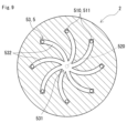
- FIG. 3 is a cross-sectional view taken along line III-III of FIG.
- FIG. 4 is a cross-sectional view of a third flow path in modification 1.
- FIG. 5 is a cross-sectional view of a third flow path in modification 2.
- FIG. FIG. 6 is a cross-sectional view of a third flow path in modification 3.
- FIG. FIG. 7 is a cross-sectional view of a third flow path in modification 4.
- FIG. FIG. 8 is a cross-sectional view of a third flow path in modification 5.
- FIG. FIG. FIG. 1 is a cross-sectional view schematically showing a film forming apparatus equipped with a heater according to Embodiment 1.
- FIG. FIG. 2 is a cross-sectional view mainly
- FIG. 9 is a cross-sectional view of a third flow path in modification 6.
- FIG. FIG. 10 is a sectional view mainly showing an enlarged substrate of the heater of Embodiment 2.
- FIG. 11 is a cross-sectional view mainly showing an enlarged substrate of the heater of Embodiment 3.
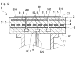
- FIG. 12 is a sectional view mainly showing an enlarged substrate of the heater of Embodiment 4.
- FIG. 13 is a cross-sectional view mainly showing an enlarged substrate of the heater of the fifth embodiment.
- Patent Document 1 has room for improvement in terms of uniformly heating the object to be heated and uniformly forming a film on the object to be heated.
- One object of the present disclosure is to provide a heater that can uniformly heat the entire surface of a heating target and that can suppress variations in film formation on the heating target.
- the heater of the present disclosure can uniformly heat the entire surface of the object to be heated, and can suppress variations in film formation on the object to be heated.
- a heater a substrate having a disk-like shape; a high-frequency electrode disposed inside the base; a heating element disposed inside the base; a support having a tubular shape;
- the substrate is a first surface on which an object to be heated is placed; a second surface to which the first end of the support is attached; a flow path connected to the first surface and the second surface;
- the flow path is a first flow path having an intake port provided on the first surface side; a second flow path having an exhaust port provided in a region inside the support on the second surface side; a third flow path that connects the first flow path and the second flow path,
- Each of the high-frequency electrode, the heating element, and the third flow path is arranged in a plane parallel to the first plane, The heating element and the third channel are arranged closer to the second surface than the high-frequency electrode.
- the object to be heated placed on the first surface is vacuum-adsorbed to the first surface by the channel provided in the base. This vacuum suction corrects the warpage even in the case of a plate-like object warped before the object to be heated is placed on the first surface.
- the object to be heated placed on the first surface can contact the first surface over the entire surface.
- the heating element is arranged in a plane parallel to the first plane. Therefore, in the heater of the present disclosure, the object to be heated placed on the first surface is uniformly heated over the entire surface by the heating element.
- the heating element and the third flow path are located closer to the second surface than the high-frequency electrode. In other words, neither the heating element nor the third channel exists between the high-frequency electrode and the first surface.
- the high frequency electrode is arranged in a plane parallel to the first plane. Since the heating element and the third flow path are not present between the high-frequency electrode and the first surface, the thickness of the substrate between the object to be heated placed on the first surface and the high-frequency electrode is ensured to be uniform. easy. Since the third flow path does not exist between the high-frequency electrode and the first surface, it is possible to suppress the occurrence of electric discharge between the object to be heated and the high-frequency electrode, thereby suppressing the occurrence of energy loss.
- a shower head that generates reactive gas used in plasma processing also serves as a high-frequency electrode paired with the high-frequency electrode, and is arranged parallel to the first surface. Since the object to be heated contacts the first surface over the entire surface, it is easy to ensure a uniform gap between the object to be heated placed on the first surface and the showerhead.
- the thickness of the substrate between the object to be heated placed on the first surface and the high-frequency electrode is ensured to be uniform, and the object to be heated placed on the first surface and the shower head By securing a uniform interval, energy is applied uniformly over the entire surface of the object to be heated. Therefore, in the heater of the present disclosure, variations in film formation on the object to be heated by plasma processing are suppressed as compared to the case where the thickness of the substrate or the spacing is non-uniform.
- the third flow path may be arranged closer to the second surface than the heating element.
- heat transfer from the heating element to the first surface is less likely to be hindered by the third flow path. Therefore, in the above embodiment, the object to be heated placed on the first surface is heated more uniformly over the entire surface by the heating element.
- the distance between the high-frequency electrode and the third channel in the thickness direction of the base may be 2 mm or more.
- the heater of the present disclosure further includes a shield electrode disposed inside the base, wherein the shield electrode is positioned in a plane parallel to the first plane, and the high-frequency electrode and the third flow path may be arranged in the plane between
- provision of the shield electrode suppresses application of energy to the third flow path.
- it since it is difficult to apply energy to the third flow path, it is easy to suppress the occurrence of electric discharge in the space forming the third flow path during film formation on the object to be heated by plasma processing.
- the number of the first flow paths may be plural, and the intake ports may be arranged side by side in the circumferential direction of the base on the first surface.
- the object to be heated placed on the first surface is vacuum-sucked to the first surface over the entire circumference.
- the number of the first flow paths is plural, the number of the second flow paths is one, and the first surface has a plurality of first air inlets as the air inlets. is provided, and lengths along the first flow path, the second flow path, and the third flow path from each of the plurality of first intake ports to the exhaust port may be the same .
- the object to be heated placed on the first surface is vacuum-sucked to the first surface by the plurality of first air inlets having the same suction force.
- the object to be heated placed on the first surface is uniformly vacuum-adsorbed to the first surface over the entire circumference.
- the number of the first flow paths is plural, the number of the second flow paths is one, and the first surface includes a second air inlet and a second air inlet as the air inlets. Three inlets are provided, and lengths along the first flow path, the second flow path, and the third flow path from each of the second intake port and the third intake port to the exhaust port may differ.
- the object to be heated placed on the first surface is vacuum-sucked to the first surface at different positions in the radial direction of the substrate.
- the number of the first flow paths is plural, the third flow paths are provided with a plurality of branch paths extending radially from the center side of the substrate, and one or a plurality of the first flow paths are provided.
- the second channel may be connected to the center side of the substrate in the third channel, and at least one of the plurality of first channels may be connected to the tip of the branched channel.
- the object to be heated placed on the first surface is uniformly vacuum-sucked to the first surface over the entire circumference.
- FIG. 1 A heater 1 according to an embodiment will be described with reference to FIGS. 1 to 3.
- FIG. The heater 1 is used in a film forming apparatus that forms a thin film on the surface of a heating target 10 by plasma processing.
- the heater 1, as shown in FIG. 1, is placed in a chamber 8 in which the ambient gas can be controlled.
- a shower head 81 is arranged on the upper surface facing the heater 1 in the chamber 8 .
- a reactive gas used in plasma processing is jetted from the showerhead 81 toward the heater 1 .
- a high-frequency oscillator (not shown) is connected to the shower head 81 .
- the shower head 81 also serves as a high frequency electrode.
- the heater 1 includes a substrate 2, a high frequency electrode 3, a heating element 4, and a support 7, as shown in FIGS.
- the heater 1 may further comprise a shield electrode 6 as shown in FIGS. 11-13.
- the high-frequency electrode 3, the heating element 4, and the shield electrode 6 are arranged inside the base 2 so as to be parallel to each other.
- the substrate 2 is provided with the flow path 5 as a configuration for vacuum-sucking the heating target 10 to the substrate 2 .
- the high-frequency electrode 3, the heating element 4, and the flow path 5 are arranged inside the substrate 2 in a specific order. If the heater 1 comprises shield electrodes 6, the shield electrodes 6 are also arranged inside the substrate 2 in a particular order.
- FIG. 1 to 3 illustrate the heater 1 of Embodiment 1.
- FIG. 4 to 9 illustrate different patterns of third channels 53 provided in the substrate 2 of the heater 1.
- FIG. Third channel 53 is part of channel 5 .
- FIG. 10 illustrates the heater 1 of the second embodiment. 10, the order of the heating element 4 and the third flow path 53 shown in FIG. 2 is reversed.
- FIG. 11 illustrates the heater 1 of Embodiment 3.
- FIG. 11 adds a shield electrode 6 to the substrate 2 shown in FIG.
- FIG. 12 illustrates the heater 1 of Embodiment 4.
- FIG. FIG. 12 adds a shield electrode 6 to the substrate 2 shown in FIG.
- FIG. 13 illustrates the heater 1 of embodiment 5.
- FIG. In FIG. 13, a shield electrode 6 is added to the substrate 2 shown in FIG.
- the high-frequency electrode 3, the heating element 4, the flow path 5, and the shield electrode 6 are exaggerated for easy understanding.
- the sizes of the substrate 2, the high-frequency electrode 3, the heating element 4, the flow path 5, the shield electrode 6, etc. are shown schematically, and do not necessarily correspond to the actual sizes. do not have.
- each configuration will be described in detail for each embodiment.
- FIG. 1 The heater 1 of Embodiment 1 will be described with reference to FIGS. 1 to 3.
- FIG. The heater 1 of Embodiment 1 includes a substrate 2, a high-frequency electrode 3, a heating element 4, and a support 7, as shown in FIGS.
- the high-frequency electrode 3, the third flow path 53 which is a part of the flow path 5, and the heating element are arranged in order from the first surface 21 side to the second surface 22 side inside the base 2. 4 are placed.
- the substrate 2 has a disk-like shape, as shown in FIG.
- the base 2 has a first surface 21 and a second surface 22, as shown in FIG.
- the first surface 21 and the second surface 22 face each other.
- a heating target 10 is placed on the first surface 21 .
- the object 10 to be heated is, for example, a silicon or compound semiconductor wafer.
- a first end portion 71 of the support 7 described later is attached to the second surface 22 .
- a plurality of holes in which terminals (not shown) connected to the high-frequency electrode 3 and the heating element 4 (to be described later) are fitted are provided in the inner region of the support 7 on the second surface 22 side.
- the terminals protrude from the second surface 22 .
- the terminals and the plurality of holes in which the terminals are fitted are not shown.
- the channel 5 is provided so as to connect the first surface 21 and the second surface 22 .
- the material of the substrate 2 is, for example, known ceramics. Ceramics are, for example, aluminum nitride, aluminum oxide, and silicon carbide.
- the material of the substrate 2 may be composed of a composite material of the above ceramics and metal. Metals are, for example, aluminum, aluminum alloys, copper, copper alloys.
- the material of the substrate 2 in this example is aluminum nitride.
- the high frequency electrode 3 is an electrode that generates plasma with the shower head 81 shown in FIG.
- the high frequency electrode 3 is grounded.
- the high-frequency electrode 3 is connected to a high-frequency oscillator different from the high-frequency oscillator connected to the showerhead 81 .
- the high frequency electrode 3 is connected to a power line (not shown). Power lines include ground lines. The power line is arranged inside a support 7, which will be described later.
- High-frequency power is supplied between the showerhead 81 and the high-frequency electrode 3 from a high-frequency oscillator (not shown).
- the reactive gas jetted from the showerhead 81 is ionized by high frequency energy to generate a plasma state.
- a chemical reaction occurs in the object to be heated 10 placed on the first surface 21 according to the plasma state of the reaction gas, and a thin film is formed on the object to be heated 10 according to the reaction gas.
- the high-frequency electrode 3 has a disk-like shape.
- the high-frequency electrode 3 is preferably arranged concentrically with the substrate 2 .
- the high-frequency electrode 3 has, for example, the same size as the object 10 to be heated.
- the high-frequency electrode 3 may be one size larger than the object 10 to be heated.
- the high frequency electrode 3 is embedded inside the base 2 .
- the high frequency electrode 3 is arranged in a plane parallel to the first plane 21 .
- the high-frequency electrode 3 is positioned closest to the first surface 21 in the thickness direction of the substrate 2 . Between the high-frequency electrode 3 and the first surface 21, the heating element 4 and the third channel 53, which will be described later, do not exist.
- a distance D1 between the high-frequency electrode 3 and the first surface 21 is, for example, about 1 mm.
- the material of the high-frequency electrode 3 is metal with excellent heat resistance.
- the metal is, for example, one selected from the group consisting of tungsten, tungsten alloys, molybdenum, molybdenum alloys, nickel, and nickel alloys.
- the form of the high-frequency electrode 3 is not particularly limited.
- the high-frequency electrode 3 is formed by screen-printing and firing a paste containing powder made of the above metal.
- the high frequency electrode 3 may consist of a plate, mesh or fabric.
- the heating element 4 is a heat source that heats the heating target 10 placed on the first surface 21 .
- the heating element 4 heats the object to be heated 10 via the base 2 .
- the heating element 4 is connected to terminals and power lines (not shown).
- the power line is arranged inside a support 7, which will be described later. Electric power is supplied to the heating element 4 from a power supply (not shown) through a power line.
- the heating element 4 is a circuit pattern formed within the plane of the substrate 2 .
- the circuit pattern is drawn with strips made up of strip-like thin lines.
- the shape of the heating element 4 is not particularly limited. When the substrate 2 is viewed from the first surface 21 side, the shape of the outer peripheral contour of the heating element 4 is generally circular. The outline of the outer periphery of the heating element 4 is formed by the arrangement of the band-shaped portions.
- the heating element 4 is preferably arranged concentrically with the substrate 2 .
- the heating element 4 is also arranged concentrically with the high-frequency electrode 3 .
- the heating element 4 is embedded inside the base 2 .
- the heating element 4 is arranged in a plane parallel to the first surface 21 .
- the heating element 4 is arranged closer to the second surface 22 than the high-frequency electrode 3 is.
- the heating element 4 is configured by, for example, bending a belt-like portion.
- the bending of the belt-like portion includes bending in a spiral shape and a meandering shape.
- the heating element 4 may have a planar portion of a predetermined shape that is wider than the belt-like portion.
- the shape of the outer peripheral contour line of the planar portion is, for example, fan-shaped or semi-circular.
- the band-like portion and the planar portion are connected in series.
- the circuit pattern of the heating element 4 is not particularly limited. The circuit pattern of the heating element 4 can be appropriately selected according to the heating temperature and the required temperature distribution.
- the material of the heating element 4 is not particularly limited as long as it can heat the heating target 10 to a desired temperature.
- the material of the heating element 4 is a metal suitable for resistance heating.
- the metal is, for example, one selected from the group consisting of stainless steel, nickel, nickel alloys, silver, silver alloys, tungsten, tungsten alloys, molybdenum, molybdenum alloys, chromium, and chromium alloys.
- a nickel alloy is, for example, nichrome.
- the form of the heating element 4 is not particularly limited.
- the heating element 4 is formed by screen-printing and firing a paste containing powder made of the above metal.
- the heating element 4 is formed by patterning a foil made of the above metal.
- the heating element 4 may be a tungsten coil or a molybdenum coil other than the circuit pattern of the belt-like portion.
- the channel 5 is a space provided inside the base 2 .
- the channel 5 is provided so as to be connected to the first surface 21 and the second surface 22, as shown in FIG.
- the channel 5 includes a first channel 51 , a second channel 52 and a third channel 53 .
- the outer shape including the third flow path 53 is indicated by a chain double-dashed line.
- FIG. 3 is a cross-sectional view of the third flow path 53 shown in FIG. 2 taken along a plane parallel to the first surface 21 .
- the intake port 510 provided on the first surface 21 side is indicated by a solid line.
- the exhaust port 520 provided on the second surface 22 side is virtually indicated by a dashed line.
- the first flow path 51 has an air inlet 510 provided on the first surface 21 side.
- the intake port 510 of this example is provided on the first surface 21 .
- the bottom surface of the wafer pocket is the first surface 21 and the first surface 21 is provided with the air inlet 510 .
- grooves are provided on the first surface 21, a plurality of air inlets 510 may be provided on the bottom surface of the grooves.
- the channel 5 of this example includes a plurality of first channels 51 .
- a plurality of intake ports 510 are arranged on the first surface 21 shown in FIG. 2, as shown in FIG. Each intake port 510 is covered with the heating target 10 placed on the first surface 21 .
- the plurality of air inlets 510 are preferably arranged side by side in the circumferential direction of the base 2 on the first surface 21 . In particular, it is preferable that the plurality of air inlets 510 be arranged at regular intervals in the circumferential direction of the base 2 on the first surface 21 (FIG. 2).
- a plurality of air inlets 510 may be arranged on each circumference of different diameters of the substrate 2 on the first surface (FIG. 2). In this example, four intake ports 510 are arranged on each circumference of two different diameters of the substrate 2 .
- the opening shape of the intake port 510 is not particularly limited.
- the opening shape of the intake port 510 of this example is circular.
- the first flow path 51 extends from each intake port 510 toward the interior of the base 2 .
- the first channel 51 extends in a direction intersecting the first surface 21 .
- the first flow path 51 of this example extends in a direction orthogonal to the first surface 21 .
- the cross-sectional shape of the first flow path 51 is not particularly limited.
- the shape of the cross section of the first flow path 51 of this example is circular, which is the same as the opening shape of the intake port 510 .
- a cross section of the first flow path 51 is a cross section cut in a direction perpendicular to the direction in which the first flow path 51 extends.
- the cross-sectional area of the first flow path 51 can be appropriately selected to the extent that good gas flowability can be ensured.
- the gas is, for example, a reaction gas.
- the total cross-sectional area of the first flow path 51 is, for example, 0.2 mm 2 or more and 2500 mm 2 or less, preferably 15 mm 2 or more and 500 mm 2 or less.
- Favorable gas flowability is ensured because the total cross-sectional area of the first flow path 51 is equal to or greater than the lower limit. Since the total cross-sectional area of the first flow path 51 is equal to or less than the upper limit value, it is easy to suppress the heat transfer from the heating element 4 from being blocked in the first flow path 51 .
- the cross-sectional area of each first flow path 51 is appropriately selected so that the total cross-sectional area of the plurality of cross-sections satisfies the above range.
- the first flow path 51 of this example has a uniform cross-sectional shape and size in the direction in which the first flow path 51 extends.
- the cross-sectional shape of the first flow path 51 may change in the middle of the extending direction of the first flow path 51 .
- the cross-sectional area of the first flow path 51 may change in the middle of the direction in which the first flow path 51 extends.
- each first flow path 51 may be the same or different.
- the first flow path 51 is provided on the first surface 21 so that the intake ports 510 are arranged on the circumferences of the substrate 2 with different diameters, the first flow path 51 positioned on the small diameter side and the first flow path 51 positioned on the large diameter side.
- the second flow path 52 includes an exhaust port 520 provided in a region inside the support 7 on the second surface 22, as shown in FIG.
- the exhaust port 520 of this example is provided on the second surface 22 .
- an exhaust port 520 is provided on the end surface of the convex portion or the bottom surface of the concave portion.
- a suction pipe 9 is connected to the exhaust port 520 .
- a vacuum pump (not shown) is connected to the suction pipe 9 .
- the inside of the flow path 5 is decompressed through the suction pipe 9 by the suction of the vacuum pump.
- the suction tube 9 is arranged inside a support 7, which will be described later.
- the channel 5 of this example includes one second channel 52 .
- one exhaust port 520 is arranged on the second surface 22 shown in FIG.
- the exhaust port 520 is preferably arranged on the center side of the base 2 on the second surface 22 .
- the exhaust port 520 of this example is provided concentrically with the center of the base 2 .
- the opening shape of the exhaust port 520 is not particularly limited.
- the opening shape of the exhaust port 520 in this example is circular.
- the second flow path 52 extends from the exhaust port 520 toward the interior of the base 2 .
- the second flow path 52 extends in a direction intersecting the second surface 22 .
- the second flow path 52 of this example extends in a direction orthogonal to the second surface 22 .
- the extending direction of the first channel 51 and the extending direction of the second channel 52 are parallel to each other and parallel to the axial direction of the substrate 2 .
- the cross-sectional shape of the second flow path 52 is not particularly limited.
- the shape of the cross section of the second flow path 52 of this example is the same circular shape as the opening shape of the exhaust port 520 .
- the cross section of the second flow path 52 is a cross section cut in a direction orthogonal to the extending direction of the second flow path 52 .
- the cross-sectional area of the second flow path 52 can be appropriately selected to the extent that good gas flowability can be ensured.
- the cross-sectional area of the second flow path 52 is 0.2 mm 2 or more and 50 mm 2 or less, preferably 2 mm 2 or more and 20 mm 2 or less.
- the area of the cross section of the second flow path 52 is equal to or more than the lower limit value, good gas flowability is ensured. Since the area of the cross section of the second channel 52 is equal to or less than the upper limit, even if the heating element 4 is arranged closer to the second surface 22 than the third channel 53, the arrangement of the heating element 4 and Heat transfer is less likely to be hindered.
- the second flow path 52 of this example has a uniform cross-sectional shape and size in the direction in which the second flow path 52 extends.
- the cross-sectional shape of the second flow path 52 may change in the middle of the extending direction of the second flow path 52 .
- the cross-sectional area of the second flow path 52 may change in the middle of the extending direction of the second flow path 52 .
- the third flow path 53 connects the first flow path 51 and the second flow path 52, as shown in FIG.
- the third flow path 53 is arranged in a plane parallel to the first surface 21 .
- the third flow path 53 extends along a plane parallel to the first plane 21 .
- the third flow path 53 is arranged closer to the second surface 22 than the high-frequency electrode 3 is.
- a distance D2 in the thickness direction of the substrate 2 between the high-frequency electrode 3 and the third channel 53 is, for example, 2 mm or more. When the distance D2 is 2 mm or more, it is easy to suppress the occurrence of discharge in the space forming the third flow path 53 when the film is formed on the object 10 to be heated by plasma processing.
- the interval D2 is, for example, 12 mm or less. When the distance D2 is 12 mm or less, the thickness of the substrate 2 is easily suppressed.
- the distance D2 is, for example, 2 mm or more and 12 mm or less, and further 4 mm or more and 8 mm or less
- the third flow path 53 of this example is arranged closer to the first surface 21 than the heating element 4 is. That is, the third flow path 53 of this example is arranged in the plane between the high-frequency electrode 3 and the heating element 4 .
- a distance D3 in the thickness direction of the substrate 2 between the heating element 4 and the third flow path 53 is, for example, 2 mm or more. When the distance D3 is 2 mm or more, the thickness of the substrate 2 between the heating element 4 and the third flow path 53 can be secured to some extent, and heat transfer from the heating element 4 via the substrate 2 can be secured. easy.
- the interval D3 is, for example, 12 mm or less. When D3 is 12 mm or less, thickening of the substrate 2 is easily suppressed.
- the distance D3 is, for example, 2 mm or more and 12 mm or less, and further 4 mm or more and 8 mm or less.
- the third channel 53 preferably has a central portion 531 and a plurality of branch channels 532, as shown in FIG.
- the third flow path 53 of this example further includes a circular path 533 that connects midway points in the extending direction of the branch paths 532 .
- a second intake port 512 and a third intake port 513 are provided as the intake port 510 .
- the central portion 531 is arranged substantially at the center of the base 2 .
- the second channel 52 shown in FIG. 2 is connected to the central portion 531 . That is, the exhaust port 520 is arranged substantially at the center of the base body 2 .
- Each branch path 532 is arranged so as to radially extend from the central portion 531 .
- Each branch 532 has the same length.
- the length of each branch path 532 is a length that reaches the peripheral edge of the object 10 to be heated.
- four branch paths 532 are arranged.
- the four branch paths 532 are arranged so as to line up at regular intervals in the circumferential direction of the base body 2 .
- the first flow path 51 shown in FIG. 2 is connected to the tip of each branched path 532 . By connecting the first flow path 51 to each tip of the plurality of branched paths 532, the first surface 21 shown in FIG. ing.
- the plurality of second air inlets 512 are arranged side by side on a single-diameter circumference of the base body 2 on the first surface 21 .
- the lengths along the first channel 51, the second channel 52, and the third channel 53 from each second intake port 512 to the exhaust port 520 are the same.
- the plurality of third air inlets 513 are arranged side by side on a single-diameter circumference of the substrate 2 on the first surface 21 .
- the lengths along the first flow path 51, the second flow path 52, and the third flow path 53 from each third intake port 513 to the exhaust port 520 are the same.
- the second intake port 512 and the third intake port 513 are arranged on each circumference of the base body 2 with different diameters on the first surface 21 .
- the lengths along the first flow path 51, the second flow path 52, and the third flow path 53 from each of the second intake port 512 and the third intake port 513 to the exhaust port 520 are different.
- the cross-sectional shape of the third flow path 53 is not particularly limited.
- the shape of the cross section of the third flow path 53 of this example is rectangular.
- a cross section of the third flow path 53 is a cross section cut in a direction perpendicular to the direction in which the third flow path 53 extends.
- the cross-sectional area of the third flow path 53 can be appropriately selected to the extent that good gas flowability can be ensured.
- a depth D5 (see FIG. 2) of the third flow path 53 is, for example, 0.2 mm or more and 8 mm or less, preferably 0.4 mm or more and 3 mm or less.
- a width W5 (see FIG. 2) of the third flow path 53 is, for example, 0.5 mm or more and 20 mm or less, preferably 1 mm or more and 6 mm or less.
- the third flow path 53 of this example has a uniform cross-sectional shape and size in the direction in which the third flow path 53 extends.
- the cross-sectional shape of the third flow path 53 may change in the middle of the extending direction of the third flow path 53 .
- the cross-sectional area of the third flow path 53 may change in the middle of the direction in which the third flow path 53 extends. Even if the cross-sectional shape or area of the third flow path 53 changes in the direction in which the third flow path 53 extends, it is preferable to satisfy the area, the depth D5, and the width W5.
- the total area of cross sections obtained by cutting the third flow path 53 along a plane parallel to the first surface 21 is, for example, 500 mm 2 or more and 30000 mm 2 or less, preferably 1500 mm 2 or more and 10000 mm 2 or less.
- Favorable gas circulation is ensured because the total area of the cross sections is equal to or greater than the lower limit. Since the total area of the cross sections is equal to or less than the upper limit, even if the heat generating element 4 is arranged closer to the second surface 22 than the third flow path 53, the heat transfer from the heat generating element 4 is prevented from being transferred to the third flow path. Inhibition by 53 is easily suppressed.
- the overlapping area of the third flow path 53 and the heating element 4 is small.
- the overlapping area is preferably smaller. The smaller the overlapping area, the more likely it is that the heat transfer from the heating element 4 will be inhibited by the third flow path 53 .
- the flow path 5 can be manufactured, for example, by the following procedure. First, a first plate in which the high-frequency electrode 3 is arranged, a second plate in which the heating element 4 is arranged, and a third plate in which the flow path 5 is provided are individually manufactured.
- the first plate in which the high-frequency electrode 3 is arranged is formed by, for example, screen-printing and firing a paste containing powder made of tungsten metal as described above.
- a plate formed by screen-printing and firing a paste containing tungsten metal powder as described above is used for the second plate in which the heating element 4 is arranged.
- a plate formed by screen-printing and firing a paste containing tungsten metal powder as described above is used.
- the boundary between the first plate and the third plate is located between the high frequency electrode 3 and the third channel 53 shown in FIG.
- a boundary between the second plate and the third plate is located between the heating element 4 and the third channel 53 shown in FIG.
- a first flow channel 51 is formed in the first plate in accordance with the shape of the flow channel 5 of the third plate.
- a second flow channel 52 is formed in the second plate in accordance with the shape of the flow channel 5 of the third plate.
- the substrate 2 manufactured by the above procedure has a third surface on which the high-frequency electrode 3 is arranged, a fourth surface on which the heating element 4 is arranged, and a fifth surface on which the third flow path 53 is arranged.
- the third, fourth, and fifth surfaces are parallel to the first surface 21 .
- the third surface, the fifth surface, and the fourth surface are positioned in order from the first surface 21 side toward the second surface 22 side.
- the support 7 supports the base 2 from the second surface 22 side, as shown in FIGS.
- the support 7 has a tubular shape.
- the shape of the support 7 is not particularly limited.
- the support 7 in this example is a cylindrical member.
- the support 7 is arranged concentrically with the base body 2 .
- the base body 2 and the support body 7 are connected so that the center of the cylindrical support body 7 and the center of the disk-shaped base body 2 are coaxial.
- the support 7 is connected to the base 2 so as to surround a power line connected to the high-frequency electrode 3 , a power line connected to the heating element 4 , and a suction tube 9 connected to the flow path 5 .
- the support 7 has a first end 71 and a second end 72 .
- Each of the first end portion 71 and the second end portion 72 has an outwardly bent flange-like shape.
- the first end 71 is attached to the second surface 22 .
- a sealing member (not shown) is arranged between the first end portion 71 and the second surface 22 .
- the second end 72 is attached to the bottom surface of the chamber 8 .
- a sealing member (not shown) is arranged between the second end portion 72 and the bottom surface of the chamber 8 .
- the chamber 8 in which the heater 1 is arranged is typically filled with corrosive gas.
- the power line (not shown) and the suction pipe 9 arranged inside the support 7 can be isolated from the corrosive gas.
- a through hole 80 is provided in a region inside the support 7 on the bottom surface of the chamber 8 .
- a power line (not shown) and the suction tube 9 are led out of the chamber 8 through the through hole 80 .
- the material of the support 7 is, for example, ceramics similar to the material of the base 2 .
- the material of the support 7 and the material of the substrate 2 may be the same or different.
- the object to be heated 10 placed on the first surface 21 is vacuum-adsorbed to the first surface 21 by the channel 5 provided on the base 2 .
- the plurality of air inlets 510 are arranged at equal intervals on each circumference of the substrate 2 with different diameters, the heating target 10 is uniformly vacuum-sucked to the first surface 21 over the entire surface.
- the warp is corrected.
- the warping is corrected. By correcting the warp, the object to be heated 10 placed on the first surface 21 can come into contact with the first surface 21 over the entire surface.
- the heating element 4 Since the heating element 4 is arranged in a plane parallel to the first surface 21 in the base 2 , the heating object 10 is uniformly heated over the entire surface by the heating element 4 .
- the high-frequency electrode 3 is positioned closest to the first surface 21 in the thickness direction in the base 2 and is arranged in a plane parallel to the first surface 21, so that the heating object 10 and the high-frequency electrode 3 A uniform thickness of the substrate 2 is ensured.
- the showerhead 81 is arranged parallel to the first surface 21 , the space between the object to be heated 10 and the showerhead 81 is uniformly secured. Therefore, energy is applied uniformly over the entire surface of the heating target 10, and variations in film formation on the heating target 10 due to plasma processing are suppressed.
- the form of the flow path 5 can be appropriately changed within a range that connects the first surface 21 and the second surface 22 and allows the object to be heated 10 placed on the first surface 21 to be vacuum-adsorbed to the first surface 21 .
- the first channel 51 and the second channel 52 are arranged corresponding to the third channel 53 .
- 4 to 9 are cross-sectional views of the third flow path 53 cut along a plane parallel to the first surface 21, as in FIG.
- the intake port 510 provided on the side of the first surface 21 shown in FIG. 2 is indicated by solid lines. 4 to 9, the exhaust port 520 provided on the side of the second surface 22 shown in FIG. 2 is virtually indicated by broken lines.
- FIG. 2 will also be referred to as necessary.
- the third flow path 53 of Modification 1 includes a plurality of branch paths 532 and a circular path 533, like the third flow path 53 of Embodiment 1. As shown in FIG. The third flow path 53 of Modification 1 differs from the third flow path 53 of Embodiment 1 in that the circular path 533 is not connected to the first flow path 51 shown in FIG. The first flow path 51 shown in FIG. 2 is connected to the tip of each branched path 532 . In this example, a plurality of first air inlets 511 are provided as the air inlet 510 .
- the lengths along the first flow path 51, the second flow path 52, and the third flow path 53 from the first intake port 511 to the exhaust port 520 are all the same.
- the channel 5 of Modification 1 is simple because the circular channel 533 is not connected to the first channel 51 shown in FIG.
- the third flow path 53 of Modification 2 includes a plurality of linear branch paths 532 radially extending from a central portion 531 as shown in FIG.
- eight branch paths 532 are arranged.
- the eight branch paths 532 are arranged so as to line up at regular intervals in the circumferential direction of the base body 2 .
- Each branch 532 has the same length.
- the length of each branch path 532 is a length that reaches the peripheral edge of the object to be heated 10 shown in FIG.
- the second channel 52 shown in FIG. 2 is connected to the central portion 531 .
- the first flow path 51 shown in FIG. 2 is connected to the tip of each branched path 532 .
- a plurality of first air inlets 511 are provided as the air inlet 510 .
- the third flow path 53 of Modification 2 has a greater number of branch paths 532 and does not include the circular path 533 shown in FIG.
- the flow path 5 of Modification 2 more first air inlets 511 are arranged in the periphery of the object 10 to be heated.
- the lengths along the first flow path 51, the second flow path 52, and the third flow path 53 from the first intake port 511 to the exhaust port 520 are all the same. Therefore, in the flow path 5 of Modification 2, the peripheral portion of the object 10 to be heated is easily vacuum-sucked uniformly in the circumferential direction of the first surface 21 .
- the flow path 5 of Modification 2 is simple because it is composed of linear branch paths 532 .
- the third flow path 53 of Modification 3 includes a circular path 533 and a connecting path 534, as shown in FIG.
- the circular path 533 is a circular flow path provided so as to face the peripheral portion of the heating target 10 shown in FIG.
- a connecting path 534 connects the central portion 531 and the circular path 533 .
- the number of connecting paths 534 is one.
- a plurality of first air inlets 511 are arranged at equal intervals along the circular path 533 as the air inlets 510 .
- the number of the third channels 53 arranged in the central region of the base 2 is less than in the first embodiment and the like. Therefore, in the flow path 5 of Modification 3, the heat transfer from the heating element 4 is less likely to be blocked by the third flow path 53 .
- the third flow path 53 of Modification 4 includes two circular paths 533 with different diameters and a plurality of connecting paths 534, as shown in FIG.
- the circular path 533 with the larger diameter is a circular flow path provided so as to face the periphery of the heating target 10 shown in FIG.
- the circular path 533 with the smaller diameter is a circular channel provided so as to face the annular portion between the central portion and the peripheral portion of the heating target 10 shown in FIG.
- One of the plurality of connecting paths 534 connects the central portion 531 and the small-diameter circular path 533 .
- the remaining four of the plurality of connecting paths 534 connect the small diameter circular path 533 and the large diameter circular path 533 .
- a plurality of first air inlets 511 are arranged at regular intervals along a large-diameter circular path 533 as the air inlets 510 .
- the third channel 53 is more likely to ensure gas flowability.
- the third flow path 53 of Modification 5 further includes a circular path 533 in addition to the third flow path 53 of Modification 2 shown in FIG.
- the circular path 533 is provided so as to connect the tips of the plurality of branch paths 532 .
- the third flow path 53 is more likely to ensure gas flowability.
- the third flow path 53 of Modification 6 includes a plurality of curved branch paths 532 radially extending from a central portion 531 .
- the third flow path 53 of Modification 6 differs from the third flow path 53 of Modification 2 in that the branched path 532 is curved, and the other points are the same.
- the peripheral edge portion of the heating target 10 is easily vacuum-sucked uniformly in the circumferential direction of the first surface 21 .
- Embodiment 2 The heater 1 of Embodiment 2 will be described with reference to FIG.
- the order of the heating element 4 and the third flow path 53 is changed compared to the heater 1 of the first embodiment.
- the third flow path 53 is arranged closer to the second surface 22 than the heating element 4 is.
- the high-frequency electrode 3, the heating element 4, and the third flow path 53 are arranged inside the base 2 in order from the first surface 21 side toward the second surface 22 side.
- the configuration of the heater 1 of the second embodiment is the same as that of the heater 1 of the first embodiment except that the order of the heating element 4 and the third flow path 53 is changed.
- the distance between the high-frequency electrode 3 and the heating element 4 in the thickness direction of the substrate 2 is, for example, 2 mm or more and 12 mm or less, and further 4 mm or more and 8 mm or less.
- the distance between the heating element 4 and the third flow path 53 in the thickness direction of the substrate 2 is, for example, 2 mm or more and 12 mm or less, more preferably 4 mm or more and 8 mm or less.
- the heater 1 of the second embodiment has the same effects as the heater 1 of the first embodiment.
- the third flow path 53 is arranged closer to the second surface 22 than the heating element 4, so that the third flow path 53 is formed between the heating element 4 and the first surface 21. not exist. That is, the thickness of the substrate 2 between the object to be heated 10 placed on the first surface 21 and the heating element 4 is easily ensured to be uniform. Therefore, in the heater 1 of the second embodiment, the hindrance of heat transfer from the heating element 4 in the third flow path 53 is more likely to be suppressed than in the heater 1 of the first embodiment. In other words, in the heater 1 of the second embodiment, compared to the heater 1 of the first embodiment, the heat transfer to the heating object 10 via the base 2 is more likely to be performed uniformly in the radial direction and the circumferential direction of the base 2 .
- the heater 1 of Embodiment 3 will be described with reference to FIG. 11 .
- the heater 1 of the third embodiment further includes a shield electrode 6 arranged inside the base 2 in contrast to the heater 1 of the first embodiment.
- the configuration of the heater 1 of Embodiment 3 is the same as that of the heater 1 of Embodiment 1 except that a shield electrode 6 is further provided.
- the shield electrode 6 is arranged in a plane parallel to the first surface 21 and in a plane between the high-frequency electrode 3 and the third channel 53 .
- the high-frequency electrode 3 , the shield electrode 6 , the third channel 53 , and the heating element 4 are arranged in order from the first surface 21 side toward the second surface 22 side inside the base 2 .
- the volume resistivity of the base body 2 may be lowered by heating by the heating element 4 depending on the constituent material of the base body 2, and discharge occurs in the third flow path 53 due to the pressure reduction in the flow path 5.
- the shield electrode 6 has a function of suppressing the occurrence of discharge within the third flow path 53 .
- the shield electrode 6 also has a function of suppressing the influence of high-frequency noise on the heating element 4 .
- the shield electrode 6 is grounded.
- the shield electrode 6 is connected to a power line (not shown). The power line is drawn outside the chamber 8 through the inside of the support 7 .
- the shield electrode 6 has a disk-like shape.
- the shield electrode 6 has a larger diameter than the high frequency electrode 3 .
- the shield electrode 6 is embedded inside the base 2 .
- the distance between the shield electrode 6 and the high-frequency electrode 3 in the thickness direction of the substrate 2 is, for example, 1 mm or more and 12 mm or less, more preferably 2 mm or more and 8 mm or less.
- the distance between the shield electrode 6 and the third channel 53 in the thickness direction of the substrate 2 is, for example, 1 mm or more and 12 mm or less, and further 2 mm or more and 8 mm or less.
- the shield electrode 6 may also be arranged in the thickness direction of the base 2 so as to face the side of the third channel 53 .
- the material of the shield electrode 6 is, for example, the same metal as the high frequency electrode 3.
- the material of the shield electrode 6 and the material of the high frequency electrode 3 may be the same or different.
- the heater 1 of the third embodiment has the same effects as the heater 1 of the first embodiment.
- the shield electrode 6 is further provided, thereby suppressing the occurrence of discharge in the space forming the third flow path 53 . If discharge occurs in the space forming the third flow path 53, the energy loss deteriorates the film formability. In addition, if discharge occurs in the space forming the third flow path 53, the substrate 2 will be damaged and the life of the heater 1 will be shortened.
- the discharge is suppressed, thereby improving the film-forming properties and suppressing the decrease in the life of the heater 1 as compared with the heater 1 of the first embodiment.
- the heater 1 of Embodiment 4 will be described with reference to FIG. 12 .
- the heater 1 according to the fourth embodiment further includes a shield electrode 6 arranged inside the base 2 in contrast to the heater 1 according to the second embodiment.
- the configuration of the heater 1 of the fourth embodiment is the same as that of the heater 1 of the second embodiment except that the shield electrode 6 is further provided.
- the configuration of the shield electrode 6 is the same as that of the shield electrode 6 in the heater 1 of the third embodiment.
- the high-frequency electrode 3, the heating element 4, the shield electrode 6, and the third flow path 53 are arranged in order from the first surface 21 side toward the second surface 22 side inside the base 2.
- the distance between the shield electrode 6 and the heating element 4 in the thickness direction of the substrate 2 is, for example, 1 mm or more and 12 mm or less, and further 2 mm or more and 8 mm or less.
- the occurrence of discharge in the space forming the third flow path 53 is suppressed, thereby improving the film-forming properties. A decrease in life is suppressed.
- the heater 1 of Embodiment 5 will be described with reference to FIG. 13 .
- the heater 1 of the fifth embodiment differs from the heater 1 of the fourth embodiment in the position of the shield electrode 6 .
- the heater 1 of Embodiment 5 has the same configuration as the heater 1 of Embodiment 4 except for the position of the shield electrode 6 .
- the high-frequency electrode 3, the shield electrode 6, the heating element 4, and the third flow path 53 are arranged in order from the first surface 21 side toward the second surface 22 side inside the base 2.
- the distance between the high-frequency electrode 3 and the shield electrode 6 in the thickness direction of the substrate 2 is, for example, 1 mm or more and 12 mm or less, more preferably 2 mm or more and 8 mm or less.
- the distance between the shield electrode 6 and the heating element 4 in the thickness direction of the substrate 2 is, for example, 1 mm or more and 12 mm or less, and further 2 mm or more and 8 mm or less.
- the occurrence of discharge in the space forming the third flow path 53 is suppressed. Suppression of this discharge improves the film-forming properties, and further suppresses the decrease in the life of the heater 1 .
- Test Example 1 In Test Example 1, channels were provided in the substrate, and the effect of the placement of the channels on the temperature uniformity of the object to be heated and the film formation on the object to be heated was investigated.
- test specimens 1-1, 1-2, 1-3 and 1-4 were prepared. Each specimen has a high-frequency electrode and a heating element inside the substrate. The specimens 1-1, 1-2, and 1-3 further have channels inside the substrate. Specimens 1-4 do not have channels inside the substrate.
- the test bodies 1-1, 1-2, and 1-3 differ in the arrangement order of the high-frequency electrode, the heating element, and the third channel, which is part of the channel. All specimens had the same substrate material, shape, and size. All specimens have the same high-frequency electrode material, shape, and size. All specimens had the same heating element material, shape, and size. The shape and size of the third channel are the same in the specimens 1-1, 1-2 and 1-3.
- the arrangement order of the high-frequency electrode, the heating element, and the third channel in each specimen is as follows.
- a high-frequency electrode, a third channel, and a heating element are arranged in order from the first surface side to the second surface side of the substrate.
- the specimen 1-1 is the same as the heater 1 shown in FIG.
- the high-frequency electrode, the heating element, and the third channel are arranged in order from the first surface side to the second surface side of the substrate.
- the specimen 1-2 is the same as the heater 1 shown in FIG.
- the third flow path, the high-frequency electrode, and the heating element are arranged in order from the first surface side to the second surface side of the substrate.
- the high-frequency electrode and the heating element are arranged in order from the first surface side to the second surface side of the substrate. In the arrangement order shown in Table 1, the left side is the first surface side and the right side is the second surface side.
- the temperature distribution with the object to be heated placed on the first surface of the substrate was obtained by simulation.
- Heat uniformity The conditions for supplying power to the heating element were to raise the temperature from room temperature to 500° C. and hold it for 5 hours. After that, a plurality of measurement points were set for the object to be heated, and the temperature at each measurement point was determined. The plurality of measurement points were provided at equal intervals in the circumferential direction around the central point of the object to be heated and the peripheral portion of the object to be heated. The difference between the highest and lowest temperatures at multiple measurement points was determined. The smaller the difference, the better the heat uniformity. Evaluation of heat uniformity shown in Table 1 is as follows. "AA” has substantially zero difference and is very excellent in heat uniformity. "A” is small although there is the above difference, and is excellent in heat uniformity. "B” has a large difference and is inferior in heat uniformity. “C” has a very large difference and is very poor in heat uniformity. Thermal uniformity can be evaluated based on temperature measurements at 17 measurement points, for example, using a known wafer thermometer.
- a thin film is formed on an object to be heated by plasma processing, and the difference between the thickest and thinnest thicknesses of the thin film is measured at a plurality of measurement points provided at equal intervals in the circumferential direction of the central point of the object to be heated and the periphery of the object to be heated. demand. The smaller the difference, the better the film formability. Evaluation of the film-forming property shown in Table 1 is as follows. "A” has a small difference and is excellent in film formability. "C” has a very large difference and is very poor in film formability. The evaluation of the film formability can be measured using a known film thickness meter at, for example, 49 measuring points.
- the test specimens 1-1 and 1-2 in which the high-frequency electrode was located on the first surface side in the thickness direction in the substrate and provided with the flow path, were excellent in heat uniformity.
- the object to be heated was vacuum-adsorbed to the first surface of the substrate by the flow path, so that the object to be heated was able to come into contact with the first surface over the entire surface. Therefore, it is considered that the specimens 1-1 and 1-2 could be heated uniformly over the entire surface.
- the third flow path is positioned closer to the second surface than the heating element, so that the heat uniformity is extremely excellent.
- the third flow path does not exist between the heating element and the first surface, the thickness of the substrate between the object to be heated and the heating element placed on the first surface is uniform. is ensured, and the heat transfer from the heating element is unlikely to be hindered in the third flow path.
- the test specimen 1-3 in which the third flow path is positioned closest to the first surface in the thickness direction in the base, has poor heat uniformity. It is considered that the test piece 1-3 was greatly affected by the hindrance of heat transfer by the third channel because the third channel was too close to the first surface. Specimens 1-4 having no flow path are extremely inferior in thermal uniformity. In the specimen 1-4, it is considered that the warpage of the object to be heated was not corrected because the passage was not provided, and the object to be heated was not in contact with the first surface over the entire surface.
- the test specimens 1-1 and 1-2 in which the high-frequency electrode was located on the first surface side in the thickness direction in the substrate and provided with the flow path, were excellent in film forming properties.
- the object to be heated is vacuum-adsorbed to the first surface of the substrate by the channel, so that the object to be heated can contact the first surface over the entire surface.
- the high-frequency electrodes in a plane parallel to the first surface, a uniform thickness of the substrate between the object to be heated and the high-frequency electrodes is ensured.
- the showerhead is arranged parallel to the first surface, a uniform distance is secured between the object to be heated and the showerhead. Therefore, in the specimens 1-1 and 1-2, it is considered that variations in film formation on the object to be heated by plasma processing are suppressed.
- Specimen 1-3 in which the third channel is positioned closest to the first surface in the thickness direction within the substrate, has very poor film-forming properties.
- the third flow path exists between the first surface and the high-frequency electrode, and the thickness of the substrate between the object to be heated and the high-frequency electrode becomes non-uniform, resulting in film formation. Variation is considered to occur.
- Specimens 1-4 having no flow path are extremely inferior in film-forming properties. In the specimen 1-4, it is considered that the warp of the object to be heated is not corrected because the passage is not provided, and the object to be heated cannot contact the first surface over the entire surface.
- Test Example 2 In Test Example 2, each of the specimens 1-1 and 1-2 in Test Example 1 was further provided with a shield electrode, and the influence of the shield electrode on the film-forming properties of the object to be heated and the life of the heater was investigated.
- Specimen 2-1 is the same as Specimen 1-1.
- Specimen 2-2 is the same as Specimen 1-2.
- a shield electrode was further arranged on the specimen 2-1.
- a shield electrode was further arranged on the specimen 2-2.
- the test pieces 2-4 and 2-5 differ in the position of the shield electrode 6.
- FIG. The materials, shapes, and sizes of the shield electrodes are the same in the specimens 2-3, 2-4, and 2-5.
- the test pieces 2-3, 2-4, and 2-5 differ in the arrangement order of the high-frequency electrode, heating element, third channel, and shield electrode.
- the arrangement order of the high-frequency electrode, the heating element, the third channel, and the shield electrode in each specimen is as follows.
- a high-frequency electrode, a shield electrode, a third channel, and a heating element are arranged in order from the first surface side to the second surface side of the substrate.
- the specimen 2-3 is the same as the heater 1 shown in FIG.
- a high-frequency electrode, a heating element, a shield electrode, and a third channel are arranged in order from the first surface side to the second surface side of the substrate.
- the specimen 2-4 is the same as the heater 1 shown in FIG.
- the high-frequency electrode, the shield electrode, the heating element, and the third channel are arranged in order from the first surface side to the second surface side of the substrate.
- the specimen 2-5 is the same as the heater 1 shown in FIG. In the arrangement order shown in Table 2, the left side is the first surface side and the right side is the second surface side.
- the object to be heated is placed on the first surface of the substrate.
- a suction pipe is connected to the exhaust port of the second channel, which is a part of the channel, and the object to be heated is vacuum-sucked to the first surface of the substrate via the channel.
- a thin film is formed on the object to be heated by plasma treatment.
- a plurality of measurement points are set on the object to be heated, and the thickness of the thin film at each measurement point is evaluated.
- the plurality of measurement points are provided at the center point of the object to be heated and the peripheral portion of the object to be heated at regular intervals in the circumferential direction. It is checked whether or not the thickness of the thin film at each measurement point has reached a predetermined thickness by plasma processing for a predetermined time. Evaluation of the film-forming property shown in Table 2 is as follows. With “A”, a thin film having a predetermined thickness is obtained in a predetermined time, and is excellent in film formability. In “B”, the film was not formed to the predetermined thickness in the predetermined time, and the film-forming property was poor.
- Heater life An operation of forming a thin film on the object to be heated by plasma processing is performed 10,000 times, and it is confirmed whether or not the substrate is damaged.
- the evaluation of heater life shown in Table 2 is as follows. "A” shows no damage on the substrate. “B” shows some damage on the substrate.
- test specimens 2-3, 2-4, and 2-5 having a shield electrode between the high-frequency electrode and the third channel are excellent in film formability.
- the shield electrode suppresses the discharge in the space forming the third flow path. Therefore, it is considered that the film formation can be performed satisfactorily without any energy loss.
- the test specimens 2-1 and 2-2 having no shield electrode were inferior in film-forming properties. In the specimens 2-1 and 2-2, discharge occurs in the space forming the third channel, and it is considered that the energy loss adversely affects the film formation.
- test specimens 2-3, 2-4, and 2-5 having the shield electrode between the high-frequency electrode and the third channel were less likely to cause damage to the substrate.
- the shield electrode suppresses the discharge in the space forming the third flow path. Therefore, it is considered that there is no adverse effect of damaging the substrate.
- the specimens 2-1 and 2-2 which do not have shield electrodes, suffer damage to their substrates. In the specimens 2-1 and 2-2, discharge is generated in the space forming the third flow path, and it is considered that the discharge has an adverse effect such as damaging the substrate.
- Reference Signs List 1 heater 2 substrate 21 first surface 22 second surface 3 high-frequency electrode 4 heating element 5 flow path 51 first flow path 510 intake port 511 first intake port 512 second intake port 513 third intake port 52 second two channels, 520 exhaust port 53 third channel, 531 central part 532 branch path 533 circular path 534 connecting path 6 shield electrode 7 support 71 first end 72 second end 8 chamber 80 through hole 81 shower head 9 suction tube 10 object to be heated D1, D2, D3 interval D5 depth, W5 width
Abstract
A heater comprising a base body having a circular plate-form shape, a high-frequency electrode disposed inside the base body, a heat-generating body disposed inside the base body, and a support body having a cylindrical shape. The base body is provided with a first surface on which an object being heated is placed, a second surface to which a first end section of the support body is attached, and a flow path linked to the first and second surfaces. The flow path is provided with a first flow path having an intake port provided on the first-surface side, a second flow path having an exhaust port provided in a region on the second-surface side that is located inward from the support body, and a third flow path linking the first and second flow paths. The high-frequency electrode, the heat-generating body, and the third flow path are each disposed in a plane parallel to the first surface. The heat-generating body and the third flow path are disposed closer to the second-surface side than is the high-frequency electrode.
Description
本開示は、ヒータに関する。
The present disclosure relates to heaters.
特許文献1は、RFプレートとヒータプレートとが空間を介在させた状態で接続されたセラミックス部材を開示する。RFプレートは、被加熱物であるウエハが載置される載置面を備える。RFプレートの内部には、ウエハにプラズマ処理を施す際に使用される高周波電極が配置されている。ヒータプレートの内部には、発熱抵抗体が配置されている。空間は、高周波電極と発熱抵抗体との間に流れるリーク電流の発生を抑制するために設けられている。
Patent Document 1 discloses a ceramic member in which an RF plate and a heater plate are connected with a space interposed therebetween. The RF plate has a mounting surface on which a wafer, which is an object to be heated, is mounted. Inside the RF plate, a high-frequency electrode used when performing plasma processing on the wafer is arranged. A heating resistor is arranged inside the heater plate. The space is provided to suppress generation of leak current flowing between the high-frequency electrode and the heating resistor.
本開示のヒータは、
円板状の形状を有する基体と、
前記基体の内部に配置された高周波電極と、
前記基体の内部に配置された発熱体と、
筒状の形状を有する支持体と、を備え、
前記基体は、
加熱対象が載置される第一面と、
前記支持体の第一端部が取り付けられた第二面と、
前記第一面及び前記第二面につながる流路と、備え、
前記流路は、
前記第一面側に設けられた吸気口を有する第一流路と、
前記第二面側における前記支持体の内側の領域に設けられた排気口を有する第二流路と、
前記第一流路と前記第二流路とをつなぐ第三流路と、を備え、
前記高周波電極、前記発熱体、及び前記第三流路の各々は、前記第一面に平行な面内に配置されており、
前記発熱体及び前記第三流路は、前記高周波電極よりも前記第二面側に配置されている。 The heater of the present disclosure is
a substrate having a disk-like shape;
a high-frequency electrode disposed inside the base;
a heating element disposed inside the base;
a support having a tubular shape;
The substrate is
a first surface on which an object to be heated is placed;
a second surface to which the first end of the support is attached;
a flow path connected to the first surface and the second surface;
The flow path is
a first flow path having an intake port provided on the first surface side;
a second flow path having an exhaust port provided in a region inside the support on the second surface side;
a third flow path that connects the first flow path and the second flow path,
Each of the high-frequency electrode, the heating element, and the third flow path is arranged in a plane parallel to the first plane,
The heating element and the third channel are arranged closer to the second surface than the high-frequency electrode.
[本開示が解決しようとする課題]
加熱対象を全面にわたって均一に加熱することが望まれる。プラズマ処理による加熱対象への成膜のばらつきを抑制することが望まれる。特許文献1の技術では、加熱対象を均一に加熱すると共に、加熱対象に均一に成膜を施すという点で改善の余地がある。 [Problems to be Solved by the Present Disclosure]
It is desired to uniformly heat the entire surface of the object to be heated. It is desirable to suppress variations in film formation on a heating target due to plasma processing. The technique ofPatent Document 1 has room for improvement in terms of uniformly heating the object to be heated and uniformly forming a film on the object to be heated.
加熱対象を全面にわたって均一に加熱することが望まれる。プラズマ処理による加熱対象への成膜のばらつきを抑制することが望まれる。特許文献1の技術では、加熱対象を均一に加熱すると共に、加熱対象に均一に成膜を施すという点で改善の余地がある。 [Problems to be Solved by the Present Disclosure]
It is desired to uniformly heat the entire surface of the object to be heated. It is desirable to suppress variations in film formation on a heating target due to plasma processing. The technique of
本開示は、加熱対象を全面にわたって均一に加熱でき、かつ加熱対象への成膜のばらつきを抑制できるヒータを提供することを目的の一つとする。
One object of the present disclosure is to provide a heater that can uniformly heat the entire surface of a heating target and that can suppress variations in film formation on the heating target.
[本開示の効果]
本開示のヒータは、加熱対象を全面にわたって均一に加熱でき、かつ加熱対象への成膜のばらつきを抑制できる。 [Effect of the present disclosure]
The heater of the present disclosure can uniformly heat the entire surface of the object to be heated, and can suppress variations in film formation on the object to be heated.
本開示のヒータは、加熱対象を全面にわたって均一に加熱でき、かつ加熱対象への成膜のばらつきを抑制できる。 [Effect of the present disclosure]
The heater of the present disclosure can uniformly heat the entire surface of the object to be heated, and can suppress variations in film formation on the object to be heated.
[本開示の実施形態の説明]
最初に本開示の実施態様を列記して説明する。 [Description of Embodiments of the Present Disclosure]
First, the embodiments of the present disclosure are listed and described.
最初に本開示の実施態様を列記して説明する。 [Description of Embodiments of the Present Disclosure]
First, the embodiments of the present disclosure are listed and described.
(1)本開示の一態様に係るヒータは、
円板状の形状を有する基体と、
前記基体の内部に配置された高周波電極と、
前記基体の内部に配置された発熱体と、
筒状の形状を有する支持体と、を備え、
前記基体は、
加熱対象が載置される第一面と、
前記支持体の第一端部が取り付けられた第二面と、
前記第一面及び前記第二面につながる流路と、備え、
前記流路は、
前記第一面側に設けられた吸気口を有する第一流路と、
前記第二面側における前記支持体の内側の領域に設けられた排気口を有する第二流路と、
前記第一流路と前記第二流路とをつなぐ第三流路と、を備え、
前記高周波電極、前記発熱体、及び前記第三流路の各々は、前記第一面に平行な面内に配置されており、
前記発熱体及び前記第三流路は、前記高周波電極よりも前記第二面側に配置されている。 (1) A heater according to one aspect of the present disclosure,
a substrate having a disk-like shape;
a high-frequency electrode disposed inside the base;
a heating element disposed inside the base;
a support having a tubular shape;
The substrate is
a first surface on which an object to be heated is placed;
a second surface to which the first end of the support is attached;
a flow path connected to the first surface and the second surface;
The flow path is
a first flow path having an intake port provided on the first surface side;
a second flow path having an exhaust port provided in a region inside the support on the second surface side;
a third flow path that connects the first flow path and the second flow path,
Each of the high-frequency electrode, the heating element, and the third flow path is arranged in a plane parallel to the first plane,
The heating element and the third channel are arranged closer to the second surface than the high-frequency electrode.
本開示のヒータでは、第一面に載置された加熱対象は、基体に設けられた流路によって第一面に真空吸着される。この真空吸着によって、加熱対象が第一面に載置される前に反りを有する板状体の場合であっても、その反りが矯正される。第一面に載置された加熱対象は、全面にわたって第一面に接触することができる。発熱体は、第一面に平行な面内に配置されている。よって、本開示のヒータでは、第一面に載置された加熱対象は、発熱体によって全面にわたって均一に加熱される。
In the heater of the present disclosure, the object to be heated placed on the first surface is vacuum-adsorbed to the first surface by the channel provided in the base. This vacuum suction corrects the warpage even in the case of a plate-like object warped before the object to be heated is placed on the first surface. The object to be heated placed on the first surface can contact the first surface over the entire surface. The heating element is arranged in a plane parallel to the first plane. Therefore, in the heater of the present disclosure, the object to be heated placed on the first surface is uniformly heated over the entire surface by the heating element.
本開示のヒータでは、発熱体及び第三流路が高周波電極よりも第二面側に位置している。つまり、高周波電極と第一面との間には、発熱体及び第三流路が存在しない。高周波電極は、第一面に平行な面内に配置されている。高周波電極と第一面との間に発熱体及び第三流路が存在しないことで、第一面に載置された加熱対象と高周波電極との間にある基体の厚さが均一に確保され易い。高周波電極と第一面との間に第三流路が存在しないことで、加熱対象と高周波電極との間で放電が生じることを抑制でき、エネルギーロスの発生を抑制できる。
In the heater of the present disclosure, the heating element and the third flow path are located closer to the second surface than the high-frequency electrode. In other words, neither the heating element nor the third channel exists between the high-frequency electrode and the first surface. The high frequency electrode is arranged in a plane parallel to the first plane. Since the heating element and the third flow path are not present between the high-frequency electrode and the first surface, the thickness of the substrate between the object to be heated placed on the first surface and the high-frequency electrode is ensured to be uniform. easy. Since the third flow path does not exist between the high-frequency electrode and the first surface, it is possible to suppress the occurrence of electric discharge between the object to be heated and the high-frequency electrode, thereby suppressing the occurrence of energy loss.
一般的に、プラズマ処理で用いられる反応ガスを発生するシャワーヘッドは、上記高周波電極と対になる高周波電極を兼ねており、第一面に平行に配置されている。加熱対象が全面にわたって第一面に接触することで、第一面に載置された加熱対象とシャワーヘッドとの間隔が均一に確保され易い。
Generally, a shower head that generates reactive gas used in plasma processing also serves as a high-frequency electrode paired with the high-frequency electrode, and is arranged parallel to the first surface. Since the object to be heated contacts the first surface over the entire surface, it is easy to ensure a uniform gap between the object to be heated placed on the first surface and the showerhead.
本開示のヒータでは、第一面に載置された加熱対象と高周波電極との間にある基体の厚さが均一に確保され、かつ第一面に載置された加熱対象とシャワーヘッドとの間隔が均一に確保されることで、加熱対象の全面にわたって均一にエネルギーが付与される。よって、本開示のヒータでは、上記基体の厚さ又は上記間隔が不均一の場合に比較して、プラズマ処理による加熱対象への成膜のばらつきが抑制される。
In the heater of the present disclosure, the thickness of the substrate between the object to be heated placed on the first surface and the high-frequency electrode is ensured to be uniform, and the object to be heated placed on the first surface and the shower head By securing a uniform interval, energy is applied uniformly over the entire surface of the object to be heated. Therefore, in the heater of the present disclosure, variations in film formation on the object to be heated by plasma processing are suppressed as compared to the case where the thickness of the substrate or the spacing is non-uniform.
(2)本開示のヒータにおいて、前記第三流路は、前記発熱体よりも前記第二面側に配置されていてもよい。
(2) In the heater of the present disclosure, the third flow path may be arranged closer to the second surface than the heating element.
上記形態では、発熱体から第一面への伝熱が第三流路で阻害され難い。よって、上記形態では、第一面に載置された加熱対象は、発熱体によって全面にわたってより均一に加熱される。
In the above configuration, heat transfer from the heating element to the first surface is less likely to be hindered by the third flow path. Therefore, in the above embodiment, the object to be heated placed on the first surface is heated more uniformly over the entire surface by the heating element.
(3)本開示のヒータにおいて、前記高周波電極と前記第三流路との前記基体の厚さ方向の間隔が2mm以上であってもよい。
(3) In the heater of the present disclosure, the distance between the high-frequency electrode and the third channel in the thickness direction of the base may be 2 mm or more.
上記形態では、上記間隔がある程度確保されることで、プラズマ処理による加熱対象への成膜時に、第三流路を構成する空間で放電が生じることが抑制され易い。
In the above-described form, by ensuring the above-described spacing to some extent, it is easy to suppress the occurrence of discharge in the space that constitutes the third flow path during film formation on the object to be heated by plasma processing.
(4)本開示のヒータにおいて、前記基体の内部に配置されたシールド電極を更に備え、前記シールド電極は、前記第一面に平行な面内であって、前記高周波電極と前記第三流路との間の面内に配置されていてもよい。
(4) The heater of the present disclosure further includes a shield electrode disposed inside the base, wherein the shield electrode is positioned in a plane parallel to the first plane, and the high-frequency electrode and the third flow path may be arranged in the plane between
上記形態では、シールド電極を備えることで、第三流路にエネルギーが付与されることが抑制される。上記形態では、第三流路にエネルギーが付与され難いことで、プラズマ処理による加熱対象への成膜時に、第三流路を構成する空間で放電が生じることが抑制され易い。
In the above embodiment, provision of the shield electrode suppresses application of energy to the third flow path. In the above configuration, since it is difficult to apply energy to the third flow path, it is easy to suppress the occurrence of electric discharge in the space forming the third flow path during film formation on the object to be heated by plasma processing.
(5)本開示のヒータにおいて、前記第一流路の数は複数であり、前記吸気口が、前記第一面において前記基体の周方向に並んで配置されていてもよい。
(5) In the heater of the present disclosure, the number of the first flow paths may be plural, and the intake ports may be arranged side by side in the circumferential direction of the base on the first surface.
上記形態では、第一面に載置された加熱対象は、全周にわたって第一面に真空吸着される。
In the above configuration, the object to be heated placed on the first surface is vacuum-sucked to the first surface over the entire circumference.
(6)本開示のヒータにおいて、前記第一流路の数は複数であり、前記第二流路の数は一つであり、前記第一面には、前記吸気口として複数の第一吸気口が設けられており、前記複数の第一吸気口の各々から前記排気口までの前記第一流路、前記第二流路、及び前記第三流路に沿った長さが同じであってもよい。
(6) In the heater of the present disclosure, the number of the first flow paths is plural, the number of the second flow paths is one, and the first surface has a plurality of first air inlets as the air inlets. is provided, and lengths along the first flow path, the second flow path, and the third flow path from each of the plurality of first intake ports to the exhaust port may be the same .
上記形態では、第一面に載置された加熱対象は、吸引力が同じ複数の第一吸気口によって第一面に真空吸着される。例えば、上記形態では、第一面に載置された加熱対象は、全周にわたって均一に第一面に真空吸着される。
In the above embodiment, the object to be heated placed on the first surface is vacuum-sucked to the first surface by the plurality of first air inlets having the same suction force. For example, in the above embodiment, the object to be heated placed on the first surface is uniformly vacuum-adsorbed to the first surface over the entire circumference.
(7)本開示のヒータにおいて、前記第一流路の数は複数であり、前記第二流路の数は一つであり、前記第一面には、前記吸気口として第二吸気口及び第三吸気口が設けられており、前記第二吸気口及び前記第三吸気口の各々から前記排気口までの前記第一流路、前記第二流路、及び前記第三流路に沿った長さが異なってもよい。
(7) In the heater of the present disclosure, the number of the first flow paths is plural, the number of the second flow paths is one, and the first surface includes a second air inlet and a second air inlet as the air inlets. Three inlets are provided, and lengths along the first flow path, the second flow path, and the third flow path from each of the second intake port and the third intake port to the exhaust port may differ.
上記形態では、第一面に載置された加熱対象は、基体の径方向の異なる位置で第一面に真空吸着される。
In the above embodiment, the object to be heated placed on the first surface is vacuum-sucked to the first surface at different positions in the radial direction of the substrate.
(8)本開示のヒータにおいて、前記第一流路の数は複数であり、前記第三流路は、前記基体の中心側から放射状に延びる複数の分岐路を備え、一つ又は複数の前記第二流路は、前記第三流路における前記基体の中心側につながっており、複数の前記第一流路の少なくとも一つは、前記分岐路の先端部につながっていてもよい。
(8) In the heater of the present disclosure, the number of the first flow paths is plural, the third flow paths are provided with a plurality of branch paths extending radially from the center side of the substrate, and one or a plurality of the first flow paths are provided. The second channel may be connected to the center side of the substrate in the third channel, and at least one of the plurality of first channels may be connected to the tip of the branched channel.
上記形態では、第一面に載置された加熱対象は、全周にわたって均一に第一面に真空吸着される。
In the above embodiment, the object to be heated placed on the first surface is uniformly vacuum-sucked to the first surface over the entire circumference.
[本開示の実施形態の詳細]
本開示のヒータの実施形態を、図面を参照して説明する。図中の同一符号は、同一名称物を示す。なお、本発明はこれらの例示に限定されるものではなく、請求の範囲によって示され、請求の範囲と均等の意味および範囲内でのすべての変更が含まれることが意図される。 [Details of the embodiment of the present disclosure]
Embodiments of heaters of the present disclosure will be described with reference to the drawings. The same reference numerals in the drawings indicate the same names. The present invention is not limited to these exemplifications, but is indicated by the scope of the claims, and is intended to include all modifications within the scope and meaning equivalent to the scope of the claims.
<全体構成>
図1から図3を参照して、実施形態のヒータ1を説明する。ヒータ1は、プラズマ処理によって加熱対象10の表面に薄膜を形成する成膜装置に利用される。ヒータ1は、図1に示すように、雰囲気ガスの制御ができるチャンバー8内に配置されている。チャンバー8内において、ヒータ1に向かい合う上面には、シャワーヘッド81が配置されている。プラズマ処理で用いられる反応ガスは、シャワーヘッド81からヒータ1に向かって噴射される。シャワーヘッド81には、図示しない高周波発信器が接続されている。シャワーヘッド81は、高周波電極を兼ねている。 <Overall composition>
Aheater 1 according to an embodiment will be described with reference to FIGS. 1 to 3. FIG. The heater 1 is used in a film forming apparatus that forms a thin film on the surface of a heating target 10 by plasma processing. The heater 1, as shown in FIG. 1, is placed in a chamber 8 in which the ambient gas can be controlled. A shower head 81 is arranged on the upper surface facing the heater 1 in the chamber 8 . A reactive gas used in plasma processing is jetted from the showerhead 81 toward the heater 1 . A high-frequency oscillator (not shown) is connected to the shower head 81 . The shower head 81 also serves as a high frequency electrode.
図1から図3を参照して、実施形態のヒータ1を説明する。ヒータ1は、プラズマ処理によって加熱対象10の表面に薄膜を形成する成膜装置に利用される。ヒータ1は、図1に示すように、雰囲気ガスの制御ができるチャンバー8内に配置されている。チャンバー8内において、ヒータ1に向かい合う上面には、シャワーヘッド81が配置されている。プラズマ処理で用いられる反応ガスは、シャワーヘッド81からヒータ1に向かって噴射される。シャワーヘッド81には、図示しない高周波発信器が接続されている。シャワーヘッド81は、高周波電極を兼ねている。 <Overall composition>
A
ヒータ1は、図1、図2、及び図10に示すように、基体2と、高周波電極3と、発熱体4と、支持体7と、を備える。ヒータ1は、図11から図13に示すように、更にシールド電極6を備えていてもよい。高周波電極3、発熱体4、及びシールド電極6は、基体2の内部に互いに平行となるように配置されている。
The heater 1 includes a substrate 2, a high frequency electrode 3, a heating element 4, and a support 7, as shown in FIGS. The heater 1 may further comprise a shield electrode 6 as shown in FIGS. 11-13. The high-frequency electrode 3, the heating element 4, and the shield electrode 6 are arranged inside the base 2 so as to be parallel to each other.
実施形態のヒータ1の特徴の一つは、加熱対象10を基体2に真空吸着する構成として、基体2に流路5を備える点にある。実施形態のヒータ1の特徴の一つは、高周波電極3、発熱体4、及び流路5が特定の順序で基体2の内部に配置されている点にある。ヒータ1がシールド電極6を備える場合、シールド電極6も、特定の順序で基体2の内部に配置されている。
One of the features of the heater 1 of the embodiment is that the substrate 2 is provided with the flow path 5 as a configuration for vacuum-sucking the heating target 10 to the substrate 2 . One of the features of the heater 1 of the embodiment is that the high-frequency electrode 3, the heating element 4, and the flow path 5 are arranged inside the substrate 2 in a specific order. If the heater 1 comprises shield electrodes 6, the shield electrodes 6 are also arranged inside the substrate 2 in a particular order.
図1から図3は、実施形態1のヒータ1を図示している。図4から図9は、ヒータ1の基体2に設けられた第三流路53の異なるパターンを図示している。第三流路53は流路5の一部である。図10は、実施形態2のヒータ1を図示している。図10は、図2に示す発熱体4と第三流路53との順序が入れ替わっている。図11は、実施形態3のヒータ1を図示している。図11は、図2に示す基体2にシールド電極6を追加している。図12は、実施形態4のヒータ1を図示している。図12は、図10に示す基体2にシールド電極6を追加している。図13は、実施形態5のヒータ1を図示している。図13は、図10に示す基体2において、図12とは別の位置にシールド電極6を追加している。各図では、分かり易いように、高周波電極3、発熱体4、流路5、及びシールド電極6を誇張して示している。各図において、基体2、高周波電極3、発熱体4、流路5、及びシールド電極6の大きさ等は模式的に示されたものであり、必ずしも実際の大きさに対応しているわけではない。以下、実施形態ごとに各構成を詳細に説明する。
1 to 3 illustrate the heater 1 of Embodiment 1. FIG. 4 to 9 illustrate different patterns of third channels 53 provided in the substrate 2 of the heater 1. FIG. Third channel 53 is part of channel 5 . FIG. 10 illustrates the heater 1 of the second embodiment. 10, the order of the heating element 4 and the third flow path 53 shown in FIG. 2 is reversed. FIG. 11 illustrates the heater 1 of Embodiment 3. FIG. FIG. 11 adds a shield electrode 6 to the substrate 2 shown in FIG. FIG. 12 illustrates the heater 1 of Embodiment 4. FIG. FIG. 12 adds a shield electrode 6 to the substrate 2 shown in FIG. FIG. 13 illustrates the heater 1 of embodiment 5. FIG. In FIG. 13, a shield electrode 6 is added to the substrate 2 shown in FIG. 10 at a position different from that in FIG. In each figure, the high-frequency electrode 3, the heating element 4, the flow path 5, and the shield electrode 6 are exaggerated for easy understanding. In each figure, the sizes of the substrate 2, the high-frequency electrode 3, the heating element 4, the flow path 5, the shield electrode 6, etc. are shown schematically, and do not necessarily correspond to the actual sizes. do not have. Hereinafter, each configuration will be described in detail for each embodiment.
<実施形態1>
図1から図3を参照して、実施形態1のヒータ1を説明する。実施形態1のヒータ1は、図1及び図2に示すように、基体2と、高周波電極3と、発熱体4と、支持体7と、を備える。実施形態1のヒータ1では、基体2の内部に第一面21側から第二面22側に向かって順に、高周波電極3、流路5の一部である第三流路53、及び発熱体4が配置されている。 <Embodiment 1>
Theheater 1 of Embodiment 1 will be described with reference to FIGS. 1 to 3. FIG. The heater 1 of Embodiment 1 includes a substrate 2, a high-frequency electrode 3, a heating element 4, and a support 7, as shown in FIGS. In the heater 1 of Embodiment 1, the high-frequency electrode 3, the third flow path 53 which is a part of the flow path 5, and the heating element are arranged in order from the first surface 21 side to the second surface 22 side inside the base 2. 4 are placed.
図1から図3を参照して、実施形態1のヒータ1を説明する。実施形態1のヒータ1は、図1及び図2に示すように、基体2と、高周波電極3と、発熱体4と、支持体7と、を備える。実施形態1のヒータ1では、基体2の内部に第一面21側から第二面22側に向かって順に、高周波電極3、流路5の一部である第三流路53、及び発熱体4が配置されている。 <
The
≪基体≫
基体2は、図3に示すように、円板状の形状を有する。基体2は、図2に示すように、第一面21と第二面22とを備える。第一面21と第二面22とは、互いに向かい合っている。第一面21には、加熱対象10が載置される。加熱対象10は、例えばシリコンや化合物半導体のウエハである。第二面22には、後述する支持体7の第一端部71が取り付けられている。第二面22側における支持体7の内側の領域には、後述する高周波電極3及び発熱体4の各々に接続された図示しない端子が嵌め込まれた複数の穴が設けられている。上記端子は第二面22から突出している。説明の便宜上、端子、及び端子が嵌め込まれた複数の穴は図示していない。 ≪Substrate≫
Thesubstrate 2 has a disk-like shape, as shown in FIG. The base 2 has a first surface 21 and a second surface 22, as shown in FIG. The first surface 21 and the second surface 22 face each other. A heating target 10 is placed on the first surface 21 . The object 10 to be heated is, for example, a silicon or compound semiconductor wafer. A first end portion 71 of the support 7 described later is attached to the second surface 22 . A plurality of holes in which terminals (not shown) connected to the high-frequency electrode 3 and the heating element 4 (to be described later) are fitted are provided in the inner region of the support 7 on the second surface 22 side. The terminals protrude from the second surface 22 . For convenience of explanation, the terminals and the plurality of holes in which the terminals are fitted are not shown.
基体2は、図3に示すように、円板状の形状を有する。基体2は、図2に示すように、第一面21と第二面22とを備える。第一面21と第二面22とは、互いに向かい合っている。第一面21には、加熱対象10が載置される。加熱対象10は、例えばシリコンや化合物半導体のウエハである。第二面22には、後述する支持体7の第一端部71が取り付けられている。第二面22側における支持体7の内側の領域には、後述する高周波電極3及び発熱体4の各々に接続された図示しない端子が嵌め込まれた複数の穴が設けられている。上記端子は第二面22から突出している。説明の便宜上、端子、及び端子が嵌め込まれた複数の穴は図示していない。 ≪Substrate≫
The
基体2の内部には、後述する流路5が設けられている。流路5は、第一面21と第二面22とをつなぐように設けられている。
A channel 5, which will be described later, is provided inside the base 2. The channel 5 is provided so as to connect the first surface 21 and the second surface 22 .
基体2の材質は、例えば、公知のセラミックスである。セラミックスは、例えば、窒化アルミニウム、酸化アルミニウム、炭化珪素である。基体2の材質は、上記セラミックスと金属との複合材料で構成されていてもよい。金属は、例えば、アルミニウム、アルミニウム合金、銅、銅合金である。本例の基体2の材質は、窒化アルミニウムである。
The material of the substrate 2 is, for example, known ceramics. Ceramics are, for example, aluminum nitride, aluminum oxide, and silicon carbide. The material of the substrate 2 may be composed of a composite material of the above ceramics and metal. Metals are, for example, aluminum, aluminum alloys, copper, copper alloys. The material of the substrate 2 in this example is aluminum nitride.
≪高周波電極≫
高周波電極3は、図1に示すシャワーヘッド81との間でプラズマを発生させる電極である。高周波電極3は接地されている。または、高周波電極3は、シャワーヘッド81に接続された高周波発信器とは別の高周波発信器に接続されている。高周波電極3は、図示しない電力線につながっている。電力線には接地線が含まれる。電力線は、後述する支持体7の内側に配置されている。図示しない高周波発信器からの高周波電力がシャワーヘッド81と高周波電極3との間に与えられる。シャワーヘッド81から噴射された反応ガスが高周波エネルギーによってイオン化してプラズマ状態を発生する。反応ガスのプラズマ状態によって第一面21に載置された加熱対象10で化学反応が生じ、反応ガスに応じて加熱対象10に薄膜が形成される。 ≪High frequency electrode≫
Thehigh frequency electrode 3 is an electrode that generates plasma with the shower head 81 shown in FIG. The high frequency electrode 3 is grounded. Alternatively, the high-frequency electrode 3 is connected to a high-frequency oscillator different from the high-frequency oscillator connected to the showerhead 81 . The high frequency electrode 3 is connected to a power line (not shown). Power lines include ground lines. The power line is arranged inside a support 7, which will be described later. High-frequency power is supplied between the showerhead 81 and the high-frequency electrode 3 from a high-frequency oscillator (not shown). The reactive gas jetted from the showerhead 81 is ionized by high frequency energy to generate a plasma state. A chemical reaction occurs in the object to be heated 10 placed on the first surface 21 according to the plasma state of the reaction gas, and a thin film is formed on the object to be heated 10 according to the reaction gas.
高周波電極3は、図1に示すシャワーヘッド81との間でプラズマを発生させる電極である。高周波電極3は接地されている。または、高周波電極3は、シャワーヘッド81に接続された高周波発信器とは別の高周波発信器に接続されている。高周波電極3は、図示しない電力線につながっている。電力線には接地線が含まれる。電力線は、後述する支持体7の内側に配置されている。図示しない高周波発信器からの高周波電力がシャワーヘッド81と高周波電極3との間に与えられる。シャワーヘッド81から噴射された反応ガスが高周波エネルギーによってイオン化してプラズマ状態を発生する。反応ガスのプラズマ状態によって第一面21に載置された加熱対象10で化学反応が生じ、反応ガスに応じて加熱対象10に薄膜が形成される。 ≪High frequency electrode≫
The
高周波電極3は、円板状の形状を有する。高周波電極3は、好ましくは基体2と同心状に配置されている。高周波電極3は、例えば、加熱対象10と同等の大きさを有する。高周波電極3は、加熱対象10よりも一回り程度大きくてもよい。高周波電極3は、基体2の内部に埋め込まれている。高周波電極3は、第一面21に平行な面内に配置されている。高周波電極3は、基体2の厚さ方向で最も第一面21側に位置する。高周波電極3と第一面21との間には、後述する発熱体4及び第三流路53は存在しない。高周波電極3と第一面21との間隔D1は、例えば1mm程度である。
The high-frequency electrode 3 has a disk-like shape. The high-frequency electrode 3 is preferably arranged concentrically with the substrate 2 . The high-frequency electrode 3 has, for example, the same size as the object 10 to be heated. The high-frequency electrode 3 may be one size larger than the object 10 to be heated. The high frequency electrode 3 is embedded inside the base 2 . The high frequency electrode 3 is arranged in a plane parallel to the first plane 21 . The high-frequency electrode 3 is positioned closest to the first surface 21 in the thickness direction of the substrate 2 . Between the high-frequency electrode 3 and the first surface 21, the heating element 4 and the third channel 53, which will be described later, do not exist. A distance D1 between the high-frequency electrode 3 and the first surface 21 is, for example, about 1 mm.
高周波電極3の材質は、耐熱性に優れる金属である。金属は、例えば、タングステン、タングステン合金、モリブデン、モリブデン合金、ニッケル、及びニッケル合金からなる群より選択される1種である。
The material of the high-frequency electrode 3 is metal with excellent heat resistance. The metal is, for example, one selected from the group consisting of tungsten, tungsten alloys, molybdenum, molybdenum alloys, nickel, and nickel alloys.
高周波電極3の形態は特に問わない。例えば、高周波電極3は、上記金属からなる粉を含んだペーストをスクリーン印刷及び焼成することで形成される。高周波電極3は、板、メッシュ、又は繊維で構成されてもよい。
The form of the high-frequency electrode 3 is not particularly limited. For example, the high-frequency electrode 3 is formed by screen-printing and firing a paste containing powder made of the above metal. The high frequency electrode 3 may consist of a plate, mesh or fabric.
≪発熱体≫
発熱体4は、第一面21に載置された加熱対象10を加熱する熱源である。発熱体4は、基体2を介して上記加熱対象10を加熱する。発熱体4は、図示しない端子及び電力線につながっている。電力線は、後述する支持体7の内側に配置されている。発熱体4には、電力線を介して図示しない電源から電力が供給される。 ≪Heat element≫
Theheating element 4 is a heat source that heats the heating target 10 placed on the first surface 21 . The heating element 4 heats the object to be heated 10 via the base 2 . The heating element 4 is connected to terminals and power lines (not shown). The power line is arranged inside a support 7, which will be described later. Electric power is supplied to the heating element 4 from a power supply (not shown) through a power line.
発熱体4は、第一面21に載置された加熱対象10を加熱する熱源である。発熱体4は、基体2を介して上記加熱対象10を加熱する。発熱体4は、図示しない端子及び電力線につながっている。電力線は、後述する支持体7の内側に配置されている。発熱体4には、電力線を介して図示しない電源から電力が供給される。 ≪Heat element≫
The
発熱体4は、基体2の平面内に形成された回路パターンである。回路パターンは、帯状の細い線からなる帯状部で描かれている。発熱体4の形状は、特に限定されない。基体2を第一面21側から平面視したとき、発熱体4の外周輪郭線の形状は、一般的には円形である。発熱体4の外周輪郭線は、帯状部の配置によって構成される。発熱体4は、好ましくは基体2と同心状に配置されている。発熱体4は、高周波電極3とも同心状に配置されている。
The heating element 4 is a circuit pattern formed within the plane of the substrate 2 . The circuit pattern is drawn with strips made up of strip-like thin lines. The shape of the heating element 4 is not particularly limited. When the substrate 2 is viewed from the first surface 21 side, the shape of the outer peripheral contour of the heating element 4 is generally circular. The outline of the outer periphery of the heating element 4 is formed by the arrangement of the band-shaped portions. The heating element 4 is preferably arranged concentrically with the substrate 2 . The heating element 4 is also arranged concentrically with the high-frequency electrode 3 .
発熱体4は、基体2の内部に埋め込まれている。発熱体4は、第一面21に平行な面内に配置されている。発熱体4は、高周波電極3よりも第二面22側に配置されている。
The heating element 4 is embedded inside the base 2 . The heating element 4 is arranged in a plane parallel to the first surface 21 . The heating element 4 is arranged closer to the second surface 22 than the high-frequency electrode 3 is.
発熱体4は、例えば帯状部を屈曲させて構成されている。帯状部の屈曲には、渦巻き状や蛇行状に屈曲することが含まれる。発熱体4は、帯状部よりも幅の広い所定形状の面状部を備えていてもよい。面状部の外周輪郭線の形状は、例えば扇状や半円状である。帯状部と面状部は一連につながっている。発熱体4の回路パターンは、特に限定されない。発熱体4の回路パターンは、加熱する温度や求められる温度分布に応じて適宜選択できる。
The heating element 4 is configured by, for example, bending a belt-like portion. The bending of the belt-like portion includes bending in a spiral shape and a meandering shape. The heating element 4 may have a planar portion of a predetermined shape that is wider than the belt-like portion. The shape of the outer peripheral contour line of the planar portion is, for example, fan-shaped or semi-circular. The band-like portion and the planar portion are connected in series. The circuit pattern of the heating element 4 is not particularly limited. The circuit pattern of the heating element 4 can be appropriately selected according to the heating temperature and the required temperature distribution.
発熱体4の材質は、加熱対象10を所望の温度に加熱できる材質であれば特に限定されない。発熱体4の材質は、抵抗加熱に好適な金属である。金属は、例えば、ステンレス鋼、ニッケル、ニッケル合金、銀、銀合金、タングステン、タングステン合金、モリブデン、モリブデン合金、クロム、及びクロム合金からなる群より選択される1種である。ニッケル合金は、例えば、ニクロムである。
The material of the heating element 4 is not particularly limited as long as it can heat the heating target 10 to a desired temperature. The material of the heating element 4 is a metal suitable for resistance heating. The metal is, for example, one selected from the group consisting of stainless steel, nickel, nickel alloys, silver, silver alloys, tungsten, tungsten alloys, molybdenum, molybdenum alloys, chromium, and chromium alloys. A nickel alloy is, for example, nichrome.
発熱体4の形態は特に問わない。例えば、発熱体4は、上記金属からなる粉を含んだペーストをスクリーン印刷及び焼成することで形成される。他に、発熱体4は、上記金属からなる箔をパターニング加工することで形成される。発熱体4は、帯状部による回路パターン以外に、タングステンコイルやモリブデンコイルであってもよい。
The form of the heating element 4 is not particularly limited. For example, the heating element 4 is formed by screen-printing and firing a paste containing powder made of the above metal. In addition, the heating element 4 is formed by patterning a foil made of the above metal. The heating element 4 may be a tungsten coil or a molybdenum coil other than the circuit pattern of the belt-like portion.
≪流路≫
流路5は、基体2の内部に設けられた空間である。流路5は、図2に示すように、第一面21及び第二面22につながるように設けられている。流路5は、第一流路51、第二流路52、及び第三流路53を備える。図2では、第三流路53を包括する外形が二点鎖線で示されている。図3は、図2に示す第三流路53を第一面21に平行な面で切断した断面図である。図3では、第一面21側に設けられた吸気口510が実線で示されている。図3では、第二面22側に設けられた排気口520が仮想的に破線で示されている。 ≪Flow path≫
Thechannel 5 is a space provided inside the base 2 . The channel 5 is provided so as to be connected to the first surface 21 and the second surface 22, as shown in FIG. The channel 5 includes a first channel 51 , a second channel 52 and a third channel 53 . In FIG. 2, the outer shape including the third flow path 53 is indicated by a chain double-dashed line. FIG. 3 is a cross-sectional view of the third flow path 53 shown in FIG. 2 taken along a plane parallel to the first surface 21 . In FIG. 3, the intake port 510 provided on the first surface 21 side is indicated by a solid line. In FIG. 3, the exhaust port 520 provided on the second surface 22 side is virtually indicated by a dashed line.
流路5は、基体2の内部に設けられた空間である。流路5は、図2に示すように、第一面21及び第二面22につながるように設けられている。流路5は、第一流路51、第二流路52、及び第三流路53を備える。図2では、第三流路53を包括する外形が二点鎖線で示されている。図3は、図2に示す第三流路53を第一面21に平行な面で切断した断面図である。図3では、第一面21側に設けられた吸気口510が実線で示されている。図3では、第二面22側に設けられた排気口520が仮想的に破線で示されている。 ≪Flow path≫
The
〔第一流路〕
第一流路51は、図2に示すように、第一面21側に設けられた吸気口510を備える。本例の吸気口510は、第一面21に設けられている。基体2に図示しないウエハポケットが設けられている場合、ウエハポケットの底面が第一面21であり、その第一面21に吸気口510が設けられている。第一面21に図示しない溝が設けられている場合、溝の底面に複数の吸気口510が設けられていてもよい。 [First flow path]
As shown in FIG. 2, thefirst flow path 51 has an air inlet 510 provided on the first surface 21 side. The intake port 510 of this example is provided on the first surface 21 . When the substrate 2 is provided with a wafer pocket (not shown), the bottom surface of the wafer pocket is the first surface 21 and the first surface 21 is provided with the air inlet 510 . When grooves (not shown) are provided on the first surface 21, a plurality of air inlets 510 may be provided on the bottom surface of the grooves.
第一流路51は、図2に示すように、第一面21側に設けられた吸気口510を備える。本例の吸気口510は、第一面21に設けられている。基体2に図示しないウエハポケットが設けられている場合、ウエハポケットの底面が第一面21であり、その第一面21に吸気口510が設けられている。第一面21に図示しない溝が設けられている場合、溝の底面に複数の吸気口510が設けられていてもよい。 [First flow path]
As shown in FIG. 2, the
本例の流路5は、複数の第一流路51を備える。図2に示す第一面21には、図3に示すように、複数の吸気口510が配置されている。各吸気口510は、第一面21に載置された加熱対象10に覆われる。複数の吸気口510は、第一面21において基体2の周方向に並んで配置されていることが好ましい。特に、複数の吸気口510は、第一面21(図2)において基体2の周方向に等間隔に並んで配置されていることが好ましい。複数の吸気口510は、第一面(図2)において基体2の異なる径の各円周上に配置されていてもよい。本例では、基体2の異なる二つの径の各円周上に四つずつ吸気口510が配置されている。
The channel 5 of this example includes a plurality of first channels 51 . A plurality of intake ports 510 are arranged on the first surface 21 shown in FIG. 2, as shown in FIG. Each intake port 510 is covered with the heating target 10 placed on the first surface 21 . The plurality of air inlets 510 are preferably arranged side by side in the circumferential direction of the base 2 on the first surface 21 . In particular, it is preferable that the plurality of air inlets 510 be arranged at regular intervals in the circumferential direction of the base 2 on the first surface 21 (FIG. 2). A plurality of air inlets 510 may be arranged on each circumference of different diameters of the substrate 2 on the first surface (FIG. 2). In this example, four intake ports 510 are arranged on each circumference of two different diameters of the substrate 2 .
吸気口510の開口形状は特に問わない。本例の吸気口510の開口形状は円形である。
The opening shape of the intake port 510 is not particularly limited. The opening shape of the intake port 510 of this example is circular.
第一流路51は、各吸気口510から基体2の内部に向かって延びている。第一流路51は、第一面21に交差する方向に延びている。本例の第一流路51は、第一面21に直交する方向に延びている。
The first flow path 51 extends from each intake port 510 toward the interior of the base 2 . The first channel 51 extends in a direction intersecting the first surface 21 . The first flow path 51 of this example extends in a direction orthogonal to the first surface 21 .
第一流路51の横断面の形状は特に問わない。本例の第一流路51の横断面の形状は、吸気口510の開口形状と同じ円形である。第一流路51の横断面は、第一流路51の延びる方向と直交する方向に切断した断面である。
The cross-sectional shape of the first flow path 51 is not particularly limited. The shape of the cross section of the first flow path 51 of this example is circular, which is the same as the opening shape of the intake port 510 . A cross section of the first flow path 51 is a cross section cut in a direction perpendicular to the direction in which the first flow path 51 extends.
第一流路51の横断面の面積は、良好な気体の流通性を確保できる程度に適宜選択できる。気体は、例えば反応ガスである。第一流路51の横断面の総面積は、例えば、0.2mm2以上2500mm2以下、好ましくは15mm2以上500mm2以下である。第一流路51の横断面の総面積が下限値以上であることで、良好な気体の流通性が確保される。第一流路51の横断面の総面積が上限値以下であることで、発熱体4からの伝熱が第一流路51で阻害されることが抑制され易い。各第一流路51の横断面の面積は、複数の横断面の総面積が上記範囲を満たすように、適宜選択される。
The cross-sectional area of the first flow path 51 can be appropriately selected to the extent that good gas flowability can be ensured. The gas is, for example, a reaction gas. The total cross-sectional area of the first flow path 51 is, for example, 0.2 mm 2 or more and 2500 mm 2 or less, preferably 15 mm 2 or more and 500 mm 2 or less. Favorable gas flowability is ensured because the total cross-sectional area of the first flow path 51 is equal to or greater than the lower limit. Since the total cross-sectional area of the first flow path 51 is equal to or less than the upper limit value, it is easy to suppress the heat transfer from the heating element 4 from being blocked in the first flow path 51 . The cross-sectional area of each first flow path 51 is appropriately selected so that the total cross-sectional area of the plurality of cross-sections satisfies the above range.
本例の第一流路51は、第一流路51の延びる方向に一様な横断面の形状及び大きさを備える。第一流路51の横断面の形状は、第一流路51の延びる方向の途中で変化してもよい。第一流路51の横断面の面積は、第一流路51の延びる方向の途中で変化してもよい。
The first flow path 51 of this example has a uniform cross-sectional shape and size in the direction in which the first flow path 51 extends. The cross-sectional shape of the first flow path 51 may change in the middle of the extending direction of the first flow path 51 . The cross-sectional area of the first flow path 51 may change in the middle of the direction in which the first flow path 51 extends.
複数の第一流路51が設けられている場合、各第一流路51の横断面の形状及び大きさは同じでもよいし、異なっていてもよい。第一面21において基体2の異なる径の円周上に吸気口510が配置されるように第一流路51が設けられている場合、小径側に位置する第一流路51と大径側に位置する第一流路51とがある。小径側に位置する第一流路51と大径側に位置する第一流路51とで、第一流路51の横断面の形状及び大きさの少なくとも一方が異なっていてもよい。
When a plurality of first flow paths 51 are provided, the cross-sectional shape and size of each first flow path 51 may be the same or different. When the first flow path 51 is provided on the first surface 21 so that the intake ports 510 are arranged on the circumferences of the substrate 2 with different diameters, the first flow path 51 positioned on the small diameter side and the first flow path 51 positioned on the large diameter side. There is a first flow path 51 that carries out. At least one of the shape and size of the cross section of the first flow path 51 may be different between the first flow path 51 positioned on the small diameter side and the first flow path 51 positioned on the large diameter side.
〔第二流路〕
第二流路52は、図2に示すように、第二面22における支持体7の内側の領域に設けられた排気口520を備える。本例の排気口520は、第二面22に設けられている。第二面22に支持体7の取付面から局所的に突出した凸部、又は局所的に窪んだ凹部が設けられている場合、凸部の端面又は凹部の底面に排気口520が設けられていてもよい。排気口520には、吸引管9が接続されている。吸引管9には、図示しない真空ポンプが接続されている。真空ポンプの吸引により、吸引管9を介して流路5内は減圧される。吸引管9は、後述する支持体7の内側に配置されている。 [Second flow path]
Thesecond flow path 52 includes an exhaust port 520 provided in a region inside the support 7 on the second surface 22, as shown in FIG. The exhaust port 520 of this example is provided on the second surface 22 . When the second surface 22 is provided with a convex portion that locally protrudes from the mounting surface of the support 7 or a concave portion that is locally depressed, an exhaust port 520 is provided on the end surface of the convex portion or the bottom surface of the concave portion. may A suction pipe 9 is connected to the exhaust port 520 . A vacuum pump (not shown) is connected to the suction pipe 9 . The inside of the flow path 5 is decompressed through the suction pipe 9 by the suction of the vacuum pump. The suction tube 9 is arranged inside a support 7, which will be described later.
第二流路52は、図2に示すように、第二面22における支持体7の内側の領域に設けられた排気口520を備える。本例の排気口520は、第二面22に設けられている。第二面22に支持体7の取付面から局所的に突出した凸部、又は局所的に窪んだ凹部が設けられている場合、凸部の端面又は凹部の底面に排気口520が設けられていてもよい。排気口520には、吸引管9が接続されている。吸引管9には、図示しない真空ポンプが接続されている。真空ポンプの吸引により、吸引管9を介して流路5内は減圧される。吸引管9は、後述する支持体7の内側に配置されている。 [Second flow path]
The
本例の流路5は、一つの第二流路52を備える。図2に示す第二面22には、図3に示すように、一つの排気口520が配置されている。排気口520は、第二面22において基体2の中心側に配置されていることが好ましい。本例の排気口520は、基体2の中心と同心に設けられている。
The channel 5 of this example includes one second channel 52 . As shown in FIG. 3, one exhaust port 520 is arranged on the second surface 22 shown in FIG. The exhaust port 520 is preferably arranged on the center side of the base 2 on the second surface 22 . The exhaust port 520 of this example is provided concentrically with the center of the base 2 .
排気口520の開口形状は特に問わない。本例の排気口520の開口形状は円形である。
The opening shape of the exhaust port 520 is not particularly limited. The opening shape of the exhaust port 520 in this example is circular.
第二流路52は、排気口520から基体2の内部に向かって延びている。第二流路52は、第二面22に交差する方向に延びている。本例の第二流路52は、第二面22に直交する方向に延びている。本例では、第一流路51の延びる方向及び第二流路52の延びる方向は、互いに平行であり、かつ基体2の軸方向と平行である。
The second flow path 52 extends from the exhaust port 520 toward the interior of the base 2 . The second flow path 52 extends in a direction intersecting the second surface 22 . The second flow path 52 of this example extends in a direction orthogonal to the second surface 22 . In this example, the extending direction of the first channel 51 and the extending direction of the second channel 52 are parallel to each other and parallel to the axial direction of the substrate 2 .
第二流路52の横断面の形状は特に問わない。本例の第二流路52の横断面の形状は、排気口520の開口形状と同じ円形である。第二流路52の横断面は、第二流路52の延びる方向と直交する方向に切断した断面である。
The cross-sectional shape of the second flow path 52 is not particularly limited. The shape of the cross section of the second flow path 52 of this example is the same circular shape as the opening shape of the exhaust port 520 . The cross section of the second flow path 52 is a cross section cut in a direction orthogonal to the extending direction of the second flow path 52 .
第二流路52の横断面の面積は、良好な気体の流通性を確保できる程度に適宜選択できる。例えば、第二流路52の横断面の面積は、0.2mm2以上50mm2以下、好ましくは2mm2以上20mm2以下である。第二流路52の横断面の面積が下限値以上であることで、良好な気体の流通性が確保される。第二流路52の横断面の面積が上限値以下であることで、発熱体4が第三流路53よりも第二面22側に配置されていたとしても、発熱体4の配置、及び伝熱が阻害され難い。
The cross-sectional area of the second flow path 52 can be appropriately selected to the extent that good gas flowability can be ensured. For example, the cross-sectional area of the second flow path 52 is 0.2 mm 2 or more and 50 mm 2 or less, preferably 2 mm 2 or more and 20 mm 2 or less. By setting the area of the cross section of the second flow path 52 to be equal to or more than the lower limit value, good gas flowability is ensured. Since the area of the cross section of the second channel 52 is equal to or less than the upper limit, even if the heating element 4 is arranged closer to the second surface 22 than the third channel 53, the arrangement of the heating element 4 and Heat transfer is less likely to be hindered.
本例の第二流路52は、第二流路52の延びる方向に一様な横断面の形状及び大きさを備える。第二流路52の横断面の形状は、第二流路52の延びる方向の途中で変化してもよい。第二流路52の横断面の面積は、第二流路52の延びる方向の途中で変化してもよい。
The second flow path 52 of this example has a uniform cross-sectional shape and size in the direction in which the second flow path 52 extends. The cross-sectional shape of the second flow path 52 may change in the middle of the extending direction of the second flow path 52 . The cross-sectional area of the second flow path 52 may change in the middle of the extending direction of the second flow path 52 .
〔第三流路〕
第三流路53は、図2に示すように、第一流路51と第二流路52とをつないでいる。第三流路53は、第一面21に平行な面内に配置されている。第三流路53は、第一面21に平行な面に沿って延びている。第三流路53は、高周波電極3よりも第二面22側に配置されている。高周波電極3と第三流路53との基体2の厚さ方向の間隔D2は、例えば2mm以上である。上記間隔D2が2mm以上であることで、プラズマ処理による加熱対象10への成膜時に、第三流路53を構成する空間で放電が生じることが抑制され易い。上記間隔D2は、例えば12mm以下である。上記間隔D2が12mm以下であることで、基体2の厚肉化が抑制され易い。上記間隔D2は、例えば2mm以上12mm以下、更に4mm以上8mm以下である。 [Third flow path]
Thethird flow path 53 connects the first flow path 51 and the second flow path 52, as shown in FIG. The third flow path 53 is arranged in a plane parallel to the first surface 21 . The third flow path 53 extends along a plane parallel to the first plane 21 . The third flow path 53 is arranged closer to the second surface 22 than the high-frequency electrode 3 is. A distance D2 in the thickness direction of the substrate 2 between the high-frequency electrode 3 and the third channel 53 is, for example, 2 mm or more. When the distance D2 is 2 mm or more, it is easy to suppress the occurrence of discharge in the space forming the third flow path 53 when the film is formed on the object 10 to be heated by plasma processing. The interval D2 is, for example, 12 mm or less. When the distance D2 is 12 mm or less, the thickness of the substrate 2 is easily suppressed. The distance D2 is, for example, 2 mm or more and 12 mm or less, and further 4 mm or more and 8 mm or less.
第三流路53は、図2に示すように、第一流路51と第二流路52とをつないでいる。第三流路53は、第一面21に平行な面内に配置されている。第三流路53は、第一面21に平行な面に沿って延びている。第三流路53は、高周波電極3よりも第二面22側に配置されている。高周波電極3と第三流路53との基体2の厚さ方向の間隔D2は、例えば2mm以上である。上記間隔D2が2mm以上であることで、プラズマ処理による加熱対象10への成膜時に、第三流路53を構成する空間で放電が生じることが抑制され易い。上記間隔D2は、例えば12mm以下である。上記間隔D2が12mm以下であることで、基体2の厚肉化が抑制され易い。上記間隔D2は、例えば2mm以上12mm以下、更に4mm以上8mm以下である。 [Third flow path]
The
本例の第三流路53は、発熱体4よりも第一面21側に配置されている。つまり、本例の第三流路53は、高周波電極3と発熱体4との間の面内に配置されている。発熱体4と第三流路53との基体2の厚さ方向の間隔D3は、例えば2mm以上である。上記間隔D3が2mm以上であることで、発熱体4と第三流路53との間にある基体2の厚さをある程度確保でき、基体2を介した発熱体4からの伝熱性が確保され易い。上記間隔D3は、例えば12mm以下である。上記D3が12mm以下であることで、基体2の厚肉化が抑制され易い。上記間隔D3は、例えば2mm以上12mm以下、更に4mm以上8mm以下である。
The third flow path 53 of this example is arranged closer to the first surface 21 than the heating element 4 is. That is, the third flow path 53 of this example is arranged in the plane between the high-frequency electrode 3 and the heating element 4 . A distance D3 in the thickness direction of the substrate 2 between the heating element 4 and the third flow path 53 is, for example, 2 mm or more. When the distance D3 is 2 mm or more, the thickness of the substrate 2 between the heating element 4 and the third flow path 53 can be secured to some extent, and heat transfer from the heating element 4 via the substrate 2 can be secured. easy. The interval D3 is, for example, 12 mm or less. When D3 is 12 mm or less, thickening of the substrate 2 is easily suppressed. The distance D3 is, for example, 2 mm or more and 12 mm or less, and further 4 mm or more and 8 mm or less.
第三流路53は、図3に示すように、中心部531、及び複数の分岐路532を備えることが好ましい。本例の第三流路53は、更に、各分岐路532の延びる方向の途中同士をつなぐ円形路533を備える。本例では、吸気口510として、第二吸気口512及び第三吸気口513が設けられている。
The third channel 53 preferably has a central portion 531 and a plurality of branch channels 532, as shown in FIG. The third flow path 53 of this example further includes a circular path 533 that connects midway points in the extending direction of the branch paths 532 . In this example, a second intake port 512 and a third intake port 513 are provided as the intake port 510 .
中心部531は、基体2の略中心に配置されている。中心部531には、図2に示す第二流路52がつながっている。つまり、基体2の略中心に排気口520が配置されている。
The central portion 531 is arranged substantially at the center of the base 2 . The second channel 52 shown in FIG. 2 is connected to the central portion 531 . That is, the exhaust port 520 is arranged substantially at the center of the base body 2 .
各分岐路532は、中心部531から放射状に延びるように配置されている。各分岐路532の長さは同じである。各分岐路532の長さは、加熱対象10の周縁部に届く長さである。本例では、4本の分岐路532が配置されている。4本の分岐路532は、基体2の周方向に等間隔に並ぶように配置されている。各分岐路532の先端部には、図2に示す第一流路51がつながっている。複数の分岐路532の各先端部に第一流路51がつながっていることで、図2に示す第一面21には、吸気口510として図3に示す複数の第二吸気口512が設けられている。複数の第二吸気口512は、第一面21において基体2の単一の径の円周上に並んで配置されている。各第二吸気口512から排気口520までの第一流路51、第二流路52、及び第三流路53に沿った長さは同じである。
Each branch path 532 is arranged so as to radially extend from the central portion 531 . Each branch 532 has the same length. The length of each branch path 532 is a length that reaches the peripheral edge of the object 10 to be heated. In this example, four branch paths 532 are arranged. The four branch paths 532 are arranged so as to line up at regular intervals in the circumferential direction of the base body 2 . The first flow path 51 shown in FIG. 2 is connected to the tip of each branched path 532 . By connecting the first flow path 51 to each tip of the plurality of branched paths 532, the first surface 21 shown in FIG. ing. The plurality of second air inlets 512 are arranged side by side on a single-diameter circumference of the base body 2 on the first surface 21 . The lengths along the first channel 51, the second channel 52, and the third channel 53 from each second intake port 512 to the exhaust port 520 are the same.
円形路533における隣り合う分岐路532間に、図2に示す第一流路51がつながっている。各分岐路532の延びる方向の途中同士をつなぐ円形路533に第一流路51がつながっていることで、図2に示す第一面21には、吸気口510として図3に示す第三吸気口513が設けられている。複数の第三吸気口513は、第一面21において基体2の単一の径の円周上に並んで配置されている。各第三吸気口513から排気口520までの第一流路51、第二流路52、及び第三流路53に沿った長さは同じである。
The first flow path 51 shown in FIG. Since the first flow path 51 is connected to the circular path 533 that connects the middle of each branch path 532 in the extending direction, the first surface 21 shown in FIG. 513 are provided. The plurality of third air inlets 513 are arranged side by side on a single-diameter circumference of the substrate 2 on the first surface 21 . The lengths along the first flow path 51, the second flow path 52, and the third flow path 53 from each third intake port 513 to the exhaust port 520 are the same.
第二吸気口512と第三吸気口513とは、第一面21において基体2の異なる径の各円周上に配置されている。第二吸気口512及び第三吸気口513の各々から排気口520までの第一流路51、第二流路52、及び第三流路53に沿った長さは異なる。
The second intake port 512 and the third intake port 513 are arranged on each circumference of the base body 2 with different diameters on the first surface 21 . The lengths along the first flow path 51, the second flow path 52, and the third flow path 53 from each of the second intake port 512 and the third intake port 513 to the exhaust port 520 are different.
第三流路53の横断面の形状は特に問わない。本例の第三流路53の横断面の形状は、矩形である。第三流路53の横断面は、第三流路53の延びる方向と直交する方向に切断した断面である。
The cross-sectional shape of the third flow path 53 is not particularly limited. The shape of the cross section of the third flow path 53 of this example is rectangular. A cross section of the third flow path 53 is a cross section cut in a direction perpendicular to the direction in which the third flow path 53 extends.
第三流路53の横断面の面積は、良好な気体の流通性を確保できる程度に適宜選択できる。第三流路53の深さD5(図2参照)は、例えば0.2mm以上8mm以下、好ましくは0.4mm以上3mm以下である。第三流路53の幅W5(図2参照)は、例えば0.5mm以上20mm以下、好ましくは1mm以上6mm以下である。
The cross-sectional area of the third flow path 53 can be appropriately selected to the extent that good gas flowability can be ensured. A depth D5 (see FIG. 2) of the third flow path 53 is, for example, 0.2 mm or more and 8 mm or less, preferably 0.4 mm or more and 3 mm or less. A width W5 (see FIG. 2) of the third flow path 53 is, for example, 0.5 mm or more and 20 mm or less, preferably 1 mm or more and 6 mm or less.
本例の第三流路53は、第三流路53の延びる方向に一様な横断面の形状及び大きさを備える。第三流路53の横断面の形状は、第三流路53の延びる方向の途中で変化してもよい。第三流路53の横断面の面積は、第三流路53の延びる方向の途中で変化してもよい。第三流路53の横断面の形状又は面積が第三流路53の延びる方向の途中で変化しても、上記面積、上記深さD5、及び上記幅W5を満たすことが好ましい。
The third flow path 53 of this example has a uniform cross-sectional shape and size in the direction in which the third flow path 53 extends. The cross-sectional shape of the third flow path 53 may change in the middle of the extending direction of the third flow path 53 . The cross-sectional area of the third flow path 53 may change in the middle of the direction in which the third flow path 53 extends. Even if the cross-sectional shape or area of the third flow path 53 changes in the direction in which the third flow path 53 extends, it is preferable to satisfy the area, the depth D5, and the width W5.
第三流路53を第一面21に平行な面に沿って切断した断面の合計面積は、例えば、500mm2以上30000mm2以下、好ましくは1500mm2以上10000mm2以下である。上記断面の合計面積が下限値以上であることで、良好な気体の流通性が確保される。上記断面の合計面積が上限値以下であることで、発熱体4が第三流路53よりも第二面22側に配置されていたとしても、発熱体4からの伝熱が第三流路53で阻害されることが抑制され易い。
The total area of cross sections obtained by cutting the third flow path 53 along a plane parallel to the first surface 21 is, for example, 500 mm 2 or more and 30000 mm 2 or less, preferably 1500 mm 2 or more and 10000 mm 2 or less. Favorable gas circulation is ensured because the total area of the cross sections is equal to or greater than the lower limit. Since the total area of the cross sections is equal to or less than the upper limit, even if the heat generating element 4 is arranged closer to the second surface 22 than the third flow path 53, the heat transfer from the heat generating element 4 is prevented from being transferred to the third flow path. Inhibition by 53 is easily suppressed.
基体2を第一面21側から平面視したとき、第三流路53と発熱体4とがオーバーラップした面積は小さい方が好ましい。特に、本例のように第三流路53が発熱体4よりも第一面21側に配置されている場合、上記オーバーラップした面積はより小さい方が好ましい。上記オーバーラップした面積が小さいほど、発熱体4からの伝熱が第三流路53で阻害されることが抑制され易い。
When the substrate 2 is viewed from the first surface 21 side, it is preferable that the overlapping area of the third flow path 53 and the heating element 4 is small. In particular, when the third flow path 53 is arranged closer to the first surface 21 than the heating element 4 as in this example, the overlapping area is preferably smaller. The smaller the overlapping area, the more likely it is that the heat transfer from the heating element 4 will be inhibited by the third flow path 53 .
流路5は、例えば以下の手順で製造できる。まず、高周波電極3が内部に配置された第一プレート、発熱体4が内部に配置された第二プレート、及び流路5が設けられた第三プレートを個別に作製する。高周波電極3が内部に配置された第一プレートには、例えば、上述したようにタングステンの金属からなる粉を含んだペーストをスクリーン印刷及び焼成して形成したものを用いる。発熱体4が内部に配置された第二プレートには、例えば、上述したようにタングステンの金属からなる粉を含んだペーストをスクリーン印刷及び焼成して形成したものを用いる。図示していないが第一プレートと第三プレートとの境界は、図2に示す高周波電極3と第三流路53との間に位置する。第二プレートと第三プレートとの境界は、図2に示す発熱体4と第三流路53との間に位置する。第一プレートには、第三プレートの流路5の形状に合わせて、第一流路51を形成しておく。第二プレートには、第三プレートの流路5の形状に合わせて第二流路52を形成しておく。最後に、第一プレート、第三プレート、第二プレートの順に重ねて接合する。
The flow path 5 can be manufactured, for example, by the following procedure. First, a first plate in which the high-frequency electrode 3 is arranged, a second plate in which the heating element 4 is arranged, and a third plate in which the flow path 5 is provided are individually manufactured. The first plate in which the high-frequency electrode 3 is arranged is formed by, for example, screen-printing and firing a paste containing powder made of tungsten metal as described above. For the second plate in which the heating element 4 is arranged, for example, a plate formed by screen-printing and firing a paste containing tungsten metal powder as described above is used. Although not shown, the boundary between the first plate and the third plate is located between the high frequency electrode 3 and the third channel 53 shown in FIG. A boundary between the second plate and the third plate is located between the heating element 4 and the third channel 53 shown in FIG. A first flow channel 51 is formed in the first plate in accordance with the shape of the flow channel 5 of the third plate. A second flow channel 52 is formed in the second plate in accordance with the shape of the flow channel 5 of the third plate. Finally, the first plate, the third plate, and the second plate are laminated in this order and joined.
上記手順で製造された基体2は、高周波電極3が配置された第三面、発熱体4が配置された第四面、及び第三流路53が配置された第五面を備える。第三面、第四面、及び第五面は、第一面21に平行な面である。本例では、第一面21側から第二面22側に向かって順に、第三面、第五面、及び第四面が位置する。
The substrate 2 manufactured by the above procedure has a third surface on which the high-frequency electrode 3 is arranged, a fourth surface on which the heating element 4 is arranged, and a fifth surface on which the third flow path 53 is arranged. The third, fourth, and fifth surfaces are parallel to the first surface 21 . In this example, the third surface, the fifth surface, and the fourth surface are positioned in order from the first surface 21 side toward the second surface 22 side.
≪支持体≫
支持体7は、図1及び図2に示すように、基体2を第二面22側から支持している。支持体7は、筒状の形状を有する。支持体7の形状は特に問わない。本例の支持体7は円筒状部材である。支持体7は、基体2と同心状に配置されている。本例では、円筒状の支持体7の中心と、円板状の基体2の中心とが同軸となるように、基体2と支持体7とが接続されている。支持体7は、高周波電極3につながる電力線、発熱体4につながる電力線、流路5につながる吸引管9を囲むように基体2に接続されている。 <<Support>>
Thesupport 7 supports the base 2 from the second surface 22 side, as shown in FIGS. The support 7 has a tubular shape. The shape of the support 7 is not particularly limited. The support 7 in this example is a cylindrical member. The support 7 is arranged concentrically with the base body 2 . In this example, the base body 2 and the support body 7 are connected so that the center of the cylindrical support body 7 and the center of the disk-shaped base body 2 are coaxial. The support 7 is connected to the base 2 so as to surround a power line connected to the high-frequency electrode 3 , a power line connected to the heating element 4 , and a suction tube 9 connected to the flow path 5 .
支持体7は、図1及び図2に示すように、基体2を第二面22側から支持している。支持体7は、筒状の形状を有する。支持体7の形状は特に問わない。本例の支持体7は円筒状部材である。支持体7は、基体2と同心状に配置されている。本例では、円筒状の支持体7の中心と、円板状の基体2の中心とが同軸となるように、基体2と支持体7とが接続されている。支持体7は、高周波電極3につながる電力線、発熱体4につながる電力線、流路5につながる吸引管9を囲むように基体2に接続されている。 <<Support>>
The
支持体7は、第一端部71及び第二端部72を備える。第一端部71及び第二端部72の各々は、外側に屈曲したフランジ状の形状を有する。第一端部71は、第二面22に取り付けられている。第一端部71と第二面22との間には、図示しないシール部材が配置されている。第二端部72は、チャンバー8の底面に取り付けられている。第二端部72とチャンバー8の底面との間には、図示しないシール部材が配置されている。これらのシール部材によって、支持体7の内部の気密が保たれている。気密を保つことができれば、第一端部71と第二面22との間、及び第二端部72とチャンバー8の底面との間の少なくとも一方は、シール部材が配置されずに直接的に接合されていてもよい。ヒータ1が配置されたチャンバー8内には、代表的には、腐食性ガスが充満される。支持体7の内部の気密が保たれることで、支持体7の内側に配置された図示しない電力線、及び吸引管9を腐食性ガスから隔離することができる。チャンバー8の底面における支持体7の内側の領域には貫通孔80が設けられている。図示しない電力線、及び吸引管9は、貫通孔80を通ってチャンバー8の外部に引き出されている。
The support 7 has a first end 71 and a second end 72 . Each of the first end portion 71 and the second end portion 72 has an outwardly bent flange-like shape. The first end 71 is attached to the second surface 22 . A sealing member (not shown) is arranged between the first end portion 71 and the second surface 22 . The second end 72 is attached to the bottom surface of the chamber 8 . A sealing member (not shown) is arranged between the second end portion 72 and the bottom surface of the chamber 8 . These sealing members keep the inside of the support 7 airtight. If airtightness can be maintained, at least one of the first end portion 71 and the second surface 22 and the second end portion 72 and the bottom surface of the chamber 8 can be directly connected without a seal member disposed therebetween. It may be joined. The chamber 8 in which the heater 1 is arranged is typically filled with corrosive gas. By keeping the inside of the support 7 airtight, the power line (not shown) and the suction pipe 9 arranged inside the support 7 can be isolated from the corrosive gas. A through hole 80 is provided in a region inside the support 7 on the bottom surface of the chamber 8 . A power line (not shown) and the suction tube 9 are led out of the chamber 8 through the through hole 80 .
支持体7の材質は、例えば、基体2の材質と同様のセラミックスである。支持体7の材質と基体2の材質とは、同じであってもよいし、異なっていてもよい。
The material of the support 7 is, for example, ceramics similar to the material of the base 2 . The material of the support 7 and the material of the substrate 2 may be the same or different.
実施形態1のヒータ1では、第一面21に載置された加熱対象10は、基体2に設けられた流路5によって第一面21に真空吸着される。特に、複数の吸気口510が基体2の異なる径の各円周上に等間隔に並んで配置されていることで、加熱対象10は全面にわたって第一面21に均一に真空吸着される。この真空吸着によって、加熱対象10が第一面21に載置される前に反りを有していたとしても、その反りが矯正される。また、加熱対象10の成膜時に、熱又は化学反応によって反りが生じそうになっても、その反りが矯正される。反りが矯正されることで、第一面21に載置された加熱対象10は、全面にわたって第一面21に接触することができる。
In the heater 1 of Embodiment 1, the object to be heated 10 placed on the first surface 21 is vacuum-adsorbed to the first surface 21 by the channel 5 provided on the base 2 . In particular, since the plurality of air inlets 510 are arranged at equal intervals on each circumference of the substrate 2 with different diameters, the heating target 10 is uniformly vacuum-sucked to the first surface 21 over the entire surface. By this vacuum suction, even if the object to be heated 10 is warped before being placed on the first surface 21, the warp is corrected. In addition, even if warping is likely to occur due to heat or chemical reaction during film formation of the object 10 to be heated, the warping is corrected. By correcting the warp, the object to be heated 10 placed on the first surface 21 can come into contact with the first surface 21 over the entire surface.
発熱体4が基体2内の第一面21に平行な面内に配置されていることで、加熱対象10は発熱体4によって全面にわたって均一に加熱される。
Since the heating element 4 is arranged in a plane parallel to the first surface 21 in the base 2 , the heating object 10 is uniformly heated over the entire surface by the heating element 4 .
高周波電極3が基体2内の厚さ方向の最も第一面21側に位置すると共に、第一面21に平行な面内に配置されていることで、加熱対象10と高周波電極3との間にある基体2の厚さが均一に確保される。また、シャワーヘッド81が第一面21に平行に配置されていることで、加熱対象10とシャワーヘッド81との間隔が均一に確保される。よって、加熱対象10の全面にわたって均一にエネルギーが付与され、プラズマ処理による加熱対象10への成膜のばらつきが抑制される。
The high-frequency electrode 3 is positioned closest to the first surface 21 in the thickness direction in the base 2 and is arranged in a plane parallel to the first surface 21, so that the heating object 10 and the high-frequency electrode 3 A uniform thickness of the substrate 2 is ensured. In addition, since the showerhead 81 is arranged parallel to the first surface 21 , the space between the object to be heated 10 and the showerhead 81 is uniformly secured. Therefore, energy is applied uniformly over the entire surface of the heating target 10, and variations in film formation on the heating target 10 due to plasma processing are suppressed.
<変形例>
流路5の形態は、第一面21及び第二面22につながり、第一面21に載置された加熱対象10を第一面21に真空吸着できる範囲において適宜変更できる。例えば、以下に説明する変形例1から変形例6のように、主に第三流路53の形態を変更できる。第一流路51及び第二流路52は、第三流路53に対応して配置される。図4から図9は、図3と同様に、第三流路53を第一面21に平行な面で切断した断面図である。図4から図9では、図2に示す第一面21側に設けられた吸気口510が実線で示されている。図4から図9では、図2に示す第二面22側に設けられた排気口520が仮想的に破線で示されている。変形例1の説明では、必要に応じて図2も参照する。 <Modification>
The form of theflow path 5 can be appropriately changed within a range that connects the first surface 21 and the second surface 22 and allows the object to be heated 10 placed on the first surface 21 to be vacuum-adsorbed to the first surface 21 . For example, it is possible to mainly change the form of the third flow path 53 as in Modifications 1 to 6 described below. The first channel 51 and the second channel 52 are arranged corresponding to the third channel 53 . 4 to 9 are cross-sectional views of the third flow path 53 cut along a plane parallel to the first surface 21, as in FIG. In FIGS. 4 to 9, the intake port 510 provided on the side of the first surface 21 shown in FIG. 2 is indicated by solid lines. 4 to 9, the exhaust port 520 provided on the side of the second surface 22 shown in FIG. 2 is virtually indicated by broken lines. In the description of Modification 1, FIG. 2 will also be referred to as necessary.
流路5の形態は、第一面21及び第二面22につながり、第一面21に載置された加熱対象10を第一面21に真空吸着できる範囲において適宜変更できる。例えば、以下に説明する変形例1から変形例6のように、主に第三流路53の形態を変更できる。第一流路51及び第二流路52は、第三流路53に対応して配置される。図4から図9は、図3と同様に、第三流路53を第一面21に平行な面で切断した断面図である。図4から図9では、図2に示す第一面21側に設けられた吸気口510が実線で示されている。図4から図9では、図2に示す第二面22側に設けられた排気口520が仮想的に破線で示されている。変形例1の説明では、必要に応じて図2も参照する。 <Modification>
The form of the
〔変形例1〕
変形例1の第三流路53は、図4に示すように、実施形態1の第三流路53と同様に、複数の分岐路532と円形路533とを備える。変形例1の第三流路53は、円形路533が図2に示す第一流路51につながっていない点が、実施形態1の第三流路53と異なる。各分岐路532の先端部には、図2に示す第一流路51がつながっている。本例では、吸気口510として、複数の第一吸気口511が設けられている。 [Modification 1]
As shown in FIG. 4, thethird flow path 53 of Modification 1 includes a plurality of branch paths 532 and a circular path 533, like the third flow path 53 of Embodiment 1. As shown in FIG. The third flow path 53 of Modification 1 differs from the third flow path 53 of Embodiment 1 in that the circular path 533 is not connected to the first flow path 51 shown in FIG. The first flow path 51 shown in FIG. 2 is connected to the tip of each branched path 532 . In this example, a plurality of first air inlets 511 are provided as the air inlet 510 .
変形例1の第三流路53は、図4に示すように、実施形態1の第三流路53と同様に、複数の分岐路532と円形路533とを備える。変形例1の第三流路53は、円形路533が図2に示す第一流路51につながっていない点が、実施形態1の第三流路53と異なる。各分岐路532の先端部には、図2に示す第一流路51がつながっている。本例では、吸気口510として、複数の第一吸気口511が設けられている。 [Modification 1]
As shown in FIG. 4, the
変形例1の流路5では、第一吸気口511から排気口520までの第一流路51、第二流路52、及び第三流路53に沿った長さが全て同じである。変形例1の流路5は、円形路533が図2に示す第一流路51がつながっていないことから、シンプルである。
In the flow path 5 of Modification 1, the lengths along the first flow path 51, the second flow path 52, and the third flow path 53 from the first intake port 511 to the exhaust port 520 are all the same. The channel 5 of Modification 1 is simple because the circular channel 533 is not connected to the first channel 51 shown in FIG.
〔変形例2〕
変形例2の第三流路53は、図5に示すように、中心部531から放射状に延びる直線状の複数の分岐路532を備える。本例では、8本の分岐路532が配置されている。8本の分岐路532は、基体2の周方向に等間隔に並ぶように配置されている。各分岐路532の長さは同じである。各分岐路532の長さは、図2に示す加熱対象10の周縁部に届く長さである。中心部531には、図2に示す第二流路52がつながっている。各分岐路532の先端部には、図2に示す第一流路51がつながっている。本例では、吸気口510として、複数の第一吸気口511が設けられている。 [Modification 2]
Thethird flow path 53 of Modification 2 includes a plurality of linear branch paths 532 radially extending from a central portion 531 as shown in FIG. In this example, eight branch paths 532 are arranged. The eight branch paths 532 are arranged so as to line up at regular intervals in the circumferential direction of the base body 2 . Each branch 532 has the same length. The length of each branch path 532 is a length that reaches the peripheral edge of the object to be heated 10 shown in FIG. The second channel 52 shown in FIG. 2 is connected to the central portion 531 . The first flow path 51 shown in FIG. 2 is connected to the tip of each branched path 532 . In this example, a plurality of first air inlets 511 are provided as the air inlet 510 .
変形例2の第三流路53は、図5に示すように、中心部531から放射状に延びる直線状の複数の分岐路532を備える。本例では、8本の分岐路532が配置されている。8本の分岐路532は、基体2の周方向に等間隔に並ぶように配置されている。各分岐路532の長さは同じである。各分岐路532の長さは、図2に示す加熱対象10の周縁部に届く長さである。中心部531には、図2に示す第二流路52がつながっている。各分岐路532の先端部には、図2に示す第一流路51がつながっている。本例では、吸気口510として、複数の第一吸気口511が設けられている。 [Modification 2]
The
変形例2の第三流路53は、実施形態1の第三流路53と比較して、分岐路532の数が多く、図3に示す円形路533を備えない。
Compared to the third flow path 53 of Embodiment 1, the third flow path 53 of Modification 2 has a greater number of branch paths 532 and does not include the circular path 533 shown in FIG.
変形例2の流路5では、加熱対象10の周縁部により多くの第一吸気口511が配置される。変形例2の流路5では、第一吸気口511から排気口520までの第一流路51、第二流路52、及び第三流路53に沿った長さが全て同じである。よって、変形例2の流路5では、加熱対象10の周縁部を第一面21の周方向に均一に真空吸着し易い。変形例2の流路5は、直線状の分岐路532で構成されているためシンプルである。
In the flow path 5 of Modification 2, more first air inlets 511 are arranged in the periphery of the object 10 to be heated. In the flow path 5 of Modification 2, the lengths along the first flow path 51, the second flow path 52, and the third flow path 53 from the first intake port 511 to the exhaust port 520 are all the same. Therefore, in the flow path 5 of Modification 2, the peripheral portion of the object 10 to be heated is easily vacuum-sucked uniformly in the circumferential direction of the first surface 21 . The flow path 5 of Modification 2 is simple because it is composed of linear branch paths 532 .
〔変形例3〕
変形例3の第三流路53は、図6に示すように、円形路533と連結路534とを備える。円形路533は、図2に示す加熱対象10の周縁部に向かい合うように設けられた円形状の流路である。連結路534は、中心部531と円形路533とをつなぐ。連結路534の数は一つである。 [Modification 3]
Thethird flow path 53 of Modification 3 includes a circular path 533 and a connecting path 534, as shown in FIG. The circular path 533 is a circular flow path provided so as to face the peripheral portion of the heating target 10 shown in FIG. A connecting path 534 connects the central portion 531 and the circular path 533 . The number of connecting paths 534 is one.
変形例3の第三流路53は、図6に示すように、円形路533と連結路534とを備える。円形路533は、図2に示す加熱対象10の周縁部に向かい合うように設けられた円形状の流路である。連結路534は、中心部531と円形路533とをつなぐ。連結路534の数は一つである。 [Modification 3]
The
変形例3の流路5では、吸気口510として、複数の第一吸気口511が円形路533に沿って等間隔に配置されている。変形例3の流路5では、実施形態1等に比較して、基体2の中心領域に配置される第三流路53が少ない。よって、変形例3の流路5では、発熱体4からの伝熱が第三流路53で阻害され難い。
In the flow path 5 of Modified Example 3, a plurality of first air inlets 511 are arranged at equal intervals along the circular path 533 as the air inlets 510 . In the channel 5 of Modified Example 3, the number of the third channels 53 arranged in the central region of the base 2 is less than in the first embodiment and the like. Therefore, in the flow path 5 of Modification 3, the heat transfer from the heating element 4 is less likely to be blocked by the third flow path 53 .
〔変形例4〕
変形例4の第三流路53は、図7に示すように、径の異なる二つの円形路533と複数の連結路534とを備える。二つの円形路533のうち大径の円形路533は、図2に示す加熱対象10の周縁部に向かい合うように設けられた円形状の流路である。二つの円形路533のうち小径の円形路533は、図2に示す加熱対象10の中心部と周縁部との間の環状部分に向かい合うように設けられた円形状の流路である。複数の連結路534のうちの一つは、中心部531と小径の円形路533とをつなぐ。複数の連結路534のうちの残りの四つは、小径の円形路533と大径の円形路533とをつなぐ。 [Modification 4]
Thethird flow path 53 of Modification 4 includes two circular paths 533 with different diameters and a plurality of connecting paths 534, as shown in FIG. Of the two circular paths 533, the circular path 533 with the larger diameter is a circular flow path provided so as to face the periphery of the heating target 10 shown in FIG. Of the two circular paths 533, the circular path 533 with the smaller diameter is a circular channel provided so as to face the annular portion between the central portion and the peripheral portion of the heating target 10 shown in FIG. One of the plurality of connecting paths 534 connects the central portion 531 and the small-diameter circular path 533 . The remaining four of the plurality of connecting paths 534 connect the small diameter circular path 533 and the large diameter circular path 533 .
変形例4の第三流路53は、図7に示すように、径の異なる二つの円形路533と複数の連結路534とを備える。二つの円形路533のうち大径の円形路533は、図2に示す加熱対象10の周縁部に向かい合うように設けられた円形状の流路である。二つの円形路533のうち小径の円形路533は、図2に示す加熱対象10の中心部と周縁部との間の環状部分に向かい合うように設けられた円形状の流路である。複数の連結路534のうちの一つは、中心部531と小径の円形路533とをつなぐ。複数の連結路534のうちの残りの四つは、小径の円形路533と大径の円形路533とをつなぐ。 [Modification 4]
The
変形例4の流路5では、吸気口510として、複数の第一吸気口511が大径の円形路533に沿って等間隔に配置されている。変形例4の流路5では、変形例3に比較して、第三流路53による気体の流通性が確保され易い。
In the flow path 5 of Modified Example 4, a plurality of first air inlets 511 are arranged at regular intervals along a large-diameter circular path 533 as the air inlets 510 . In the channel 5 of Modified Example 4, as compared with Modified Example 3, the third channel 53 is more likely to ensure gas flowability.
〔変形例5〕
変形例5の第三流路53は、図8に示すように、図5に示す変形例2の第三流路53に更に円形路533を備える。円形路533は、複数の分岐路532の先端部をつなぐように設けられている。変形例5の流路5では、変形例2に比較して、第三流路53による気体の流通性が確保され易い。 [Modification 5]
As shown in FIG. 8, thethird flow path 53 of Modification 5 further includes a circular path 533 in addition to the third flow path 53 of Modification 2 shown in FIG. The circular path 533 is provided so as to connect the tips of the plurality of branch paths 532 . In the flow path 5 of Modification 5, as compared with Modification 2, the third flow path 53 is more likely to ensure gas flowability.
変形例5の第三流路53は、図8に示すように、図5に示す変形例2の第三流路53に更に円形路533を備える。円形路533は、複数の分岐路532の先端部をつなぐように設けられている。変形例5の流路5では、変形例2に比較して、第三流路53による気体の流通性が確保され易い。 [Modification 5]
As shown in FIG. 8, the
〔変形例6〕
変形例6の第三流路53は、図9に示すように、中心部531から放射状に延びる曲線状の複数の分岐路532を備える。変形例6の第三流路53は、変形例2の第三流路53と比較して、分岐路532が曲線状である点が異なり、その他の点は同じである。変形例6の流路5では、変形例2の流路5と同様に、加熱対象10の周縁部を第一面21の周方向に均一に真空吸着し易い。変形例6の流路5では、変形例2に比較して、曲線の曲がり具合で流通抵抗を調整し易い。 [Modification 6]
As shown in FIG. 9, thethird flow path 53 of Modification 6 includes a plurality of curved branch paths 532 radially extending from a central portion 531 . The third flow path 53 of Modification 6 differs from the third flow path 53 of Modification 2 in that the branched path 532 is curved, and the other points are the same. In the flow path 5 of Modification 6, similarly to the flow path 5 of Modification 2, the peripheral edge portion of the heating target 10 is easily vacuum-sucked uniformly in the circumferential direction of the first surface 21 . In the flow path 5 of Modified Example 6, compared with Modified Example 2, it is easier to adjust the flow resistance by the degree of curvature of the curve.
変形例6の第三流路53は、図9に示すように、中心部531から放射状に延びる曲線状の複数の分岐路532を備える。変形例6の第三流路53は、変形例2の第三流路53と比較して、分岐路532が曲線状である点が異なり、その他の点は同じである。変形例6の流路5では、変形例2の流路5と同様に、加熱対象10の周縁部を第一面21の周方向に均一に真空吸着し易い。変形例6の流路5では、変形例2に比較して、曲線の曲がり具合で流通抵抗を調整し易い。 [Modification 6]
As shown in FIG. 9, the
<実施形態2>
図10を参照して、実施形態2のヒータ1を説明する。実施形態2のヒータ1は、実施形態1のヒータ1と比較して、発熱体4と第三流路53との順序が入れ替わっている。実施形態1のヒータ1では、第三流路53は、発熱体4よりも第二面22側に配置されている。実施形態2のヒータ1では、基体2の内部に第一面21側から第二面22側に向かって順に、高周波電極3、発熱体4、及び第三流路53が配置されている。実施形態2のヒータ1において、実施形態1のヒータ1に対して、発熱体4と第三流路53との順序が入れ替わっている点以外の構成は同じである。 <Embodiment 2>
Theheater 1 of Embodiment 2 will be described with reference to FIG. In the heater 1 of the second embodiment, the order of the heating element 4 and the third flow path 53 is changed compared to the heater 1 of the first embodiment. In the heater 1 of Embodiment 1, the third flow path 53 is arranged closer to the second surface 22 than the heating element 4 is. In the heater 1 of Embodiment 2, the high-frequency electrode 3, the heating element 4, and the third flow path 53 are arranged inside the base 2 in order from the first surface 21 side toward the second surface 22 side. The configuration of the heater 1 of the second embodiment is the same as that of the heater 1 of the first embodiment except that the order of the heating element 4 and the third flow path 53 is changed.
図10を参照して、実施形態2のヒータ1を説明する。実施形態2のヒータ1は、実施形態1のヒータ1と比較して、発熱体4と第三流路53との順序が入れ替わっている。実施形態1のヒータ1では、第三流路53は、発熱体4よりも第二面22側に配置されている。実施形態2のヒータ1では、基体2の内部に第一面21側から第二面22側に向かって順に、高周波電極3、発熱体4、及び第三流路53が配置されている。実施形態2のヒータ1において、実施形態1のヒータ1に対して、発熱体4と第三流路53との順序が入れ替わっている点以外の構成は同じである。 <
The
高周波電極3と発熱体4との基体2の厚さ方向の間隔は、例えば2mm以上12mm以下、更に4mm以上8mm以下である。発熱体4と第三流路53との基体2の厚さ方向の間隔は、例えば2mm以上12mm以下、更に4mm以上8mm以下である。
The distance between the high-frequency electrode 3 and the heating element 4 in the thickness direction of the substrate 2 is, for example, 2 mm or more and 12 mm or less, and further 4 mm or more and 8 mm or less. The distance between the heating element 4 and the third flow path 53 in the thickness direction of the substrate 2 is, for example, 2 mm or more and 12 mm or less, more preferably 4 mm or more and 8 mm or less.
実施形態2のヒータ1は、実施形態1のヒータ1と同様の効果を奏する。実施形態2のヒータ1では、第三流路53が発熱体4よりも第二面22側に配置されていることで、発熱体4と第一面21との間に第三流路53が存在しない。つまり、第一面21に載置された加熱対象10と発熱体4との間にある基体2の厚さが均一に確保され易い。そのため、実施形態2のヒータ1では、実施形態1のヒータ1に比較して、発熱体4からの伝熱は第三流路53で阻害されることがより抑制され易い。言い換えると、実施形態2のヒータ1では、実施形態1のヒータ1に比較して、基体2を介した加熱対象10への伝熱が基体2の径方向及び周方向に均一に行われ易い。
The heater 1 of the second embodiment has the same effects as the heater 1 of the first embodiment. In the heater 1 of Embodiment 2, the third flow path 53 is arranged closer to the second surface 22 than the heating element 4, so that the third flow path 53 is formed between the heating element 4 and the first surface 21. not exist. That is, the thickness of the substrate 2 between the object to be heated 10 placed on the first surface 21 and the heating element 4 is easily ensured to be uniform. Therefore, in the heater 1 of the second embodiment, the hindrance of heat transfer from the heating element 4 in the third flow path 53 is more likely to be suppressed than in the heater 1 of the first embodiment. In other words, in the heater 1 of the second embodiment, compared to the heater 1 of the first embodiment, the heat transfer to the heating object 10 via the base 2 is more likely to be performed uniformly in the radial direction and the circumferential direction of the base 2 .
<実施形態3>
図11を参照して、実施形態3のヒータ1を説明する。実施形態3のヒータ1は、実施形態1のヒータ1に対して、基体2の内部に配置されたシールド電極6を更に備える。実施形態3のヒータ1において、実施形態1のヒータ1に対して、シールド電極6を更に備える点以外の構成は同じである。 <Embodiment 3>
Theheater 1 of Embodiment 3 will be described with reference to FIG. 11 . The heater 1 of the third embodiment further includes a shield electrode 6 arranged inside the base 2 in contrast to the heater 1 of the first embodiment. The configuration of the heater 1 of Embodiment 3 is the same as that of the heater 1 of Embodiment 1 except that a shield electrode 6 is further provided.
図11を参照して、実施形態3のヒータ1を説明する。実施形態3のヒータ1は、実施形態1のヒータ1に対して、基体2の内部に配置されたシールド電極6を更に備える。実施形態3のヒータ1において、実施形態1のヒータ1に対して、シールド電極6を更に備える点以外の構成は同じである。 <
The
≪シールド電極≫
シールド電極6は、第一面21に平行な面内であって、高周波電極3と第三流路53との間の面内に配置されている。本例では、基体2の内部に第一面21側から第二面22側に向かって順に、高周波電極3、シールド電極6、第三流路53、及び発熱体4が配置されている。基体2では、基体2の構成材料によっては発熱体4による加熱で基体2の体積抵抗率が低下し得ること、及び流路5内が減圧されることによって、第三流路53で放電が生じ易い。シールド電極6は、第三流路53内で放電が生じることを抑制する機能を備える。シールド電極6は、更に発熱体4への高周波ノイズの影響を抑制する機能も備える。シールド電極6は接地されている。シールド電極6は、図示しない電力線につながっている。電力線は、支持体7の内側を通ってチャンバー8の外部に引き出されている。 ≪Shield electrode≫
Theshield electrode 6 is arranged in a plane parallel to the first surface 21 and in a plane between the high-frequency electrode 3 and the third channel 53 . In this example, the high-frequency electrode 3 , the shield electrode 6 , the third channel 53 , and the heating element 4 are arranged in order from the first surface 21 side toward the second surface 22 side inside the base 2 . In the base body 2, the volume resistivity of the base body 2 may be lowered by heating by the heating element 4 depending on the constituent material of the base body 2, and discharge occurs in the third flow path 53 due to the pressure reduction in the flow path 5. easy. The shield electrode 6 has a function of suppressing the occurrence of discharge within the third flow path 53 . The shield electrode 6 also has a function of suppressing the influence of high-frequency noise on the heating element 4 . The shield electrode 6 is grounded. The shield electrode 6 is connected to a power line (not shown). The power line is drawn outside the chamber 8 through the inside of the support 7 .
シールド電極6は、第一面21に平行な面内であって、高周波電極3と第三流路53との間の面内に配置されている。本例では、基体2の内部に第一面21側から第二面22側に向かって順に、高周波電極3、シールド電極6、第三流路53、及び発熱体4が配置されている。基体2では、基体2の構成材料によっては発熱体4による加熱で基体2の体積抵抗率が低下し得ること、及び流路5内が減圧されることによって、第三流路53で放電が生じ易い。シールド電極6は、第三流路53内で放電が生じることを抑制する機能を備える。シールド電極6は、更に発熱体4への高周波ノイズの影響を抑制する機能も備える。シールド電極6は接地されている。シールド電極6は、図示しない電力線につながっている。電力線は、支持体7の内側を通ってチャンバー8の外部に引き出されている。 ≪Shield electrode≫
The
シールド電極6は、円板状の形状を有する。シールド電極6は、高周波電極3よりも大きい直径を有する。シールド電極6は、基体2の内部に埋め込まれている。シールド電極6と高周波電極3との基体2の厚さ方向の間隔は、例えば1mm以上12mm以下、更に2mm以上8mm以下である。シールド電極6と第三流路53との基体2の厚さ方向の間隔は、例えば1mm以上12mm以下、更に2mm以上8mm以下である。
The shield electrode 6 has a disk-like shape. The shield electrode 6 has a larger diameter than the high frequency electrode 3 . The shield electrode 6 is embedded inside the base 2 . The distance between the shield electrode 6 and the high-frequency electrode 3 in the thickness direction of the substrate 2 is, for example, 1 mm or more and 12 mm or less, more preferably 2 mm or more and 8 mm or less. The distance between the shield electrode 6 and the third channel 53 in the thickness direction of the substrate 2 is, for example, 1 mm or more and 12 mm or less, and further 2 mm or more and 8 mm or less.
シールド電極6は、更に第三流路53の側部に向かい合うように基体2の厚さ方向にも配置されていてもよい。
The shield electrode 6 may also be arranged in the thickness direction of the base 2 so as to face the side of the third channel 53 .
シールド電極6の材質は、例えば、高周波電極3と同様の金属である。シールド電極6の材質と高周波電極3の材質とは、同じであってもよいし、異なっていてもよい。
The material of the shield electrode 6 is, for example, the same metal as the high frequency electrode 3. The material of the shield electrode 6 and the material of the high frequency electrode 3 may be the same or different.
実施形態3のヒータ1は、実施形態1のヒータ1と同様の効果を奏する。実施形態3のヒータ1では、シールド電極6を更に備えることで、第三流路53を構成する空間で放電が生じることが抑制される。第三流路53を構成する空間で放電が生じると、エネルギーロスによって成膜性が悪化する。他に、第三流路53を構成する空間で放電が生じると、基体2にダメージが生じ、ヒータ1の寿命が短くなる。実施形態3のヒータ1では、実施形態1のヒータ1に比較して、上記放電を抑制することで、成膜性が向上され、更にヒータ1の寿命の低下が抑制される。
The heater 1 of the third embodiment has the same effects as the heater 1 of the first embodiment. In the heater 1 of Embodiment 3, the shield electrode 6 is further provided, thereby suppressing the occurrence of discharge in the space forming the third flow path 53 . If discharge occurs in the space forming the third flow path 53, the energy loss deteriorates the film formability. In addition, if discharge occurs in the space forming the third flow path 53, the substrate 2 will be damaged and the life of the heater 1 will be shortened. In the heater 1 of the third embodiment, the discharge is suppressed, thereby improving the film-forming properties and suppressing the decrease in the life of the heater 1 as compared with the heater 1 of the first embodiment.
<実施形態4>
図12を参照して、実施形態4のヒータ1を説明する。実施形態4のヒータ1は、実施形態2のヒータ1に対して、基体2の内部に配置されたシールド電極6を更に備える。実施形態4のヒータ1において、実施形態2のヒータ1に対して、シールド電極6を更に備える点以外の構成は同じである。シールド電極6の構成は、実施形態3のヒータ1におけるシールド電極6と同じである。 <Embodiment 4>
Theheater 1 of Embodiment 4 will be described with reference to FIG. 12 . The heater 1 according to the fourth embodiment further includes a shield electrode 6 arranged inside the base 2 in contrast to the heater 1 according to the second embodiment. The configuration of the heater 1 of the fourth embodiment is the same as that of the heater 1 of the second embodiment except that the shield electrode 6 is further provided. The configuration of the shield electrode 6 is the same as that of the shield electrode 6 in the heater 1 of the third embodiment.
図12を参照して、実施形態4のヒータ1を説明する。実施形態4のヒータ1は、実施形態2のヒータ1に対して、基体2の内部に配置されたシールド電極6を更に備える。実施形態4のヒータ1において、実施形態2のヒータ1に対して、シールド電極6を更に備える点以外の構成は同じである。シールド電極6の構成は、実施形態3のヒータ1におけるシールド電極6と同じである。 <
The
本例では、基体2の内部に第一面21側から第二面22側に向かって順に、高周波電極3、発熱体4、シールド電極6、及び第三流路53が配置されている。シールド電極6と発熱体4との基体2の厚さ方向の間隔は、例えば1mm以上12mm以下、更に2mm以上8mm以下である。
In this example, the high-frequency electrode 3, the heating element 4, the shield electrode 6, and the third flow path 53 are arranged in order from the first surface 21 side toward the second surface 22 side inside the base 2. The distance between the shield electrode 6 and the heating element 4 in the thickness direction of the substrate 2 is, for example, 1 mm or more and 12 mm or less, and further 2 mm or more and 8 mm or less.
実施形態4のヒータ1では、実施形態3のヒータ1と同様に、第三流路53を構成する空間で放電が生じることが抑制されることで、成膜性が向上され、更にヒータ1の寿命の低下が抑制される。
In the heater 1 of Embodiment 4, similarly to the heater 1 of Embodiment 3, the occurrence of discharge in the space forming the third flow path 53 is suppressed, thereby improving the film-forming properties. A decrease in life is suppressed.
<実施形態5>
図13を参照して、実施形態5のヒータ1を説明する。実施形態5のヒータ1は、実施形態4のヒータ1に対して、シールド電極6の位置が異なる。実施形態5のヒータ1は、シールド電極6の位置を除いて実施形態4のヒータ1と同じ構成を備える。 <Embodiment 5>
Theheater 1 of Embodiment 5 will be described with reference to FIG. 13 . The heater 1 of the fifth embodiment differs from the heater 1 of the fourth embodiment in the position of the shield electrode 6 . The heater 1 of Embodiment 5 has the same configuration as the heater 1 of Embodiment 4 except for the position of the shield electrode 6 .
図13を参照して、実施形態5のヒータ1を説明する。実施形態5のヒータ1は、実施形態4のヒータ1に対して、シールド電極6の位置が異なる。実施形態5のヒータ1は、シールド電極6の位置を除いて実施形態4のヒータ1と同じ構成を備える。 <
The
本例では、基体2の内部に第一面21側から第二面22側に向かって順に、高周波電極3、シールド電極6、発熱体4、及び第三流路53が配置されている。高周波電極3とシールド電極6との基体2の厚さ方向の間隔は、例えば1mm以上12mm以下、更に2mm以上8mm以下である。シールド電極6と発熱体4との基体2の厚さ方向の間隔は、例えば1mm以上12mm以下、更に2mm以上8mm以下である。
In this example, the high-frequency electrode 3, the shield electrode 6, the heating element 4, and the third flow path 53 are arranged in order from the first surface 21 side toward the second surface 22 side inside the base 2. The distance between the high-frequency electrode 3 and the shield electrode 6 in the thickness direction of the substrate 2 is, for example, 1 mm or more and 12 mm or less, more preferably 2 mm or more and 8 mm or less. The distance between the shield electrode 6 and the heating element 4 in the thickness direction of the substrate 2 is, for example, 1 mm or more and 12 mm or less, and further 2 mm or more and 8 mm or less.
実施形態5のヒータ1では、実施形態4のヒータ1と同様に、第三流路53を構成する空間で放電が生じることが抑制される。この放電の抑制により、成膜性が向上され、更にヒータ1の寿命の低下が抑制される。
In the heater 1 of Embodiment 5, as with the heater 1 of Embodiment 4, the occurrence of discharge in the space forming the third flow path 53 is suppressed. Suppression of this discharge improves the film-forming properties, and further suppresses the decrease in the life of the heater 1 .
[試験例1]
試験例1では、基体に流路を設け、その流路の配置が加熱対象への均熱性及び加熱対象への成膜性におよぼす影響を調べた。 [Test Example 1]
In Test Example 1, channels were provided in the substrate, and the effect of the placement of the channels on the temperature uniformity of the object to be heated and the film formation on the object to be heated was investigated.
≪試験体≫
以下の試験体1-1、1-2、1-3、及び1-4を準備した。いずれの試験体も、基体の内部に高周波電極及び発熱体を備える。試験体1-1、1-2、及び1-3は、基体の内部に更に流路を備える。試験体1-4は、基体の内部に流路を備えない。試験体1-1、1-2、及び1-3は、高周波電極、発熱体、及び流路の一部である第三流路の配置順序が異なる。いずれの試験体も、基体の材質、形状、及びサイズは同じである。いずれの試験体も、高周波電極の材質、形状、及びサイズは同じである。いずれの試験体も、発熱体の材質、形状、及びサイズは同じである。試験体1-1、1-2、及び1-3において、第三流路の形状及びサイズは同じである。各試験体における高周波電極、発熱体、及び第三流路の配置順序は、以下の通りである。 ≪Test body≫
The following test specimens 1-1, 1-2, 1-3 and 1-4 were prepared. Each specimen has a high-frequency electrode and a heating element inside the substrate. The specimens 1-1, 1-2, and 1-3 further have channels inside the substrate. Specimens 1-4 do not have channels inside the substrate. The test bodies 1-1, 1-2, and 1-3 differ in the arrangement order of the high-frequency electrode, the heating element, and the third channel, which is part of the channel. All specimens had the same substrate material, shape, and size. All specimens have the same high-frequency electrode material, shape, and size. All specimens had the same heating element material, shape, and size. The shape and size of the third channel are the same in the specimens 1-1, 1-2 and 1-3. The arrangement order of the high-frequency electrode, the heating element, and the third channel in each specimen is as follows.
試験体1-1では、基体の第一面側から第二面側に向かって順に、高周波電極、第三流路、及び発熱体が配置されている。試験体1-1は、図2に示すヒータ1と同じである。
試験体1-2では、基体の第一面側から第二面側に向かって順に、高周波電極、発熱体、及び第三流路が配置されている。試験体1-2は、図10に示すヒータ1と同じである。
試験体1-3では、基体の第一面側から第二面側に向かって順に、第三流路、高周波電極、及び発熱体が配置されている。
試験体1-4では、基体の第一面側から第二面側に向かって順に、高周波電極、及び発熱体が配置されている。
表1に示す配置順序では、左側が第一面側、右側が第二面側として記載している。 In the specimen 1-1, a high-frequency electrode, a third channel, and a heating element are arranged in order from the first surface side to the second surface side of the substrate. The specimen 1-1 is the same as theheater 1 shown in FIG.
In the specimen 1-2, the high-frequency electrode, the heating element, and the third channel are arranged in order from the first surface side to the second surface side of the substrate. The specimen 1-2 is the same as theheater 1 shown in FIG.
In the specimen 1-3, the third flow path, the high-frequency electrode, and the heating element are arranged in order from the first surface side to the second surface side of the substrate.
In the specimen 1-4, the high-frequency electrode and the heating element are arranged in order from the first surface side to the second surface side of the substrate.
In the arrangement order shown in Table 1, the left side is the first surface side and the right side is the second surface side.
試験体1-2では、基体の第一面側から第二面側に向かって順に、高周波電極、発熱体、及び第三流路が配置されている。試験体1-2は、図10に示すヒータ1と同じである。
試験体1-3では、基体の第一面側から第二面側に向かって順に、第三流路、高周波電極、及び発熱体が配置されている。
試験体1-4では、基体の第一面側から第二面側に向かって順に、高周波電極、及び発熱体が配置されている。
表1に示す配置順序では、左側が第一面側、右側が第二面側として記載している。 In the specimen 1-1, a high-frequency electrode, a third channel, and a heating element are arranged in order from the first surface side to the second surface side of the substrate. The specimen 1-1 is the same as the
In the specimen 1-2, the high-frequency electrode, the heating element, and the third channel are arranged in order from the first surface side to the second surface side of the substrate. The specimen 1-2 is the same as the
In the specimen 1-3, the third flow path, the high-frequency electrode, and the heating element are arranged in order from the first surface side to the second surface side of the substrate.
In the specimen 1-4, the high-frequency electrode and the heating element are arranged in order from the first surface side to the second surface side of the substrate.
In the arrangement order shown in Table 1, the left side is the first surface side and the right side is the second surface side.
各試験体において、基体の第一面に加熱対象を載置した状態の温度分布をシミュレーションにて求めた。
For each test piece, the temperature distribution with the object to be heated placed on the first surface of the substrate was obtained by simulation.
≪均熱性≫
発熱体に給電する条件は、常温から500℃まで昇温させ、5時間保持とした。その後、加熱対象に複数の測定点を設定し、各測定点の温度を求めた。上記複数の測定点は、加熱対象の中心点、及び加熱対象の周縁部を周方向に等間隔に設けた。複数の測定点における最も高い温度と最も低い温度との差を求めた。上記差が小さいほど、均熱性に優れる。表1に示す均熱性の評価は次の通りである。「AA」は、上記差が実質的にゼロであり、均熱性に非常に優れる。「A」は、上記差があるものの小さく、均熱性に優れる。「B」は、上記差が大きく、均熱性に劣る。「C」は、上記差が非常に大きく、均熱性に非常に劣る。均熱性の評価は、既知のウエハ温度計を用いて、例えば17点の測定点での測温値に基づいて評価できる。 ≪Heat uniformity≫
The conditions for supplying power to the heating element were to raise the temperature from room temperature to 500° C. and hold it for 5 hours. After that, a plurality of measurement points were set for the object to be heated, and the temperature at each measurement point was determined. The plurality of measurement points were provided at equal intervals in the circumferential direction around the central point of the object to be heated and the peripheral portion of the object to be heated. The difference between the highest and lowest temperatures at multiple measurement points was determined. The smaller the difference, the better the heat uniformity. Evaluation of heat uniformity shown in Table 1 is as follows. "AA" has substantially zero difference and is very excellent in heat uniformity. "A" is small although there is the above difference, and is excellent in heat uniformity. "B" has a large difference and is inferior in heat uniformity. "C" has a very large difference and is very poor in heat uniformity. Thermal uniformity can be evaluated based on temperature measurements at 17 measurement points, for example, using a known wafer thermometer.
≪成膜性≫
プラズマ処理により加熱対象に薄膜を形成し、加熱対象の中心点、及び加熱対象の周縁部を周方向に等間隔に設けた複数の測定点における薄膜の最も厚い厚さと最も薄い厚さとの差を求める。上記差が小さいほど、成膜性に優れる。表1に示す成膜性の評価は次の通りである。「A」は、上記差が小さく、成膜性に優れる。「C」は、上記差が非常に大きく、成膜性に非常に劣る。成膜性の評価は、例えば49点の測定点について既知の膜厚計を用いて測定することができる。 ≪Film formability≫
A thin film is formed on an object to be heated by plasma processing, and the difference between the thickest and thinnest thicknesses of the thin film is measured at a plurality of measurement points provided at equal intervals in the circumferential direction of the central point of the object to be heated and the periphery of the object to be heated. demand. The smaller the difference, the better the film formability. Evaluation of the film-forming property shown in Table 1 is as follows. "A" has a small difference and is excellent in film formability. "C" has a very large difference and is very poor in film formability. The evaluation of the film formability can be measured using a known film thickness meter at, for example, 49 measuring points.

≪均熱性に関して≫
表1に示すように、高周波電極が基体内の厚さ方向の最も第一面側に位置し、かつ流路を備える試験体1-1及び1-2は、均熱性に優れる。試験体1-1及び1-2では、流路によって加熱対象が基体の第一面に真空吸着されることで、加熱対象が全面にわたって第一面に接触することができたと考えられる。よって、試験体1-1及び1-2では、加熱対象を全面にわたって均一に加熱できたと考えられる。特に、試験体1-2では、第三流路が発熱体よりも第二面側に位置することで、均熱性に非常に優れる。試験体1-2では、発熱体と第一面との間に第三流路が存在しないので、第一面に載置された加熱対象と発熱体との間にある基体の厚さが均一に確保され、発熱体からの伝熱が第三流路で阻害され難いと考えられる。 ≪Regarding heat uniformity≫
As shown in Table 1, the test specimens 1-1 and 1-2, in which the high-frequency electrode was located on the first surface side in the thickness direction in the substrate and provided with the flow path, were excellent in heat uniformity. In the test specimens 1-1 and 1-2, it is considered that the object to be heated was vacuum-adsorbed to the first surface of the substrate by the flow path, so that the object to be heated was able to come into contact with the first surface over the entire surface. Therefore, it is considered that the specimens 1-1 and 1-2 could be heated uniformly over the entire surface. In particular, in the test sample 1-2, the third flow path is positioned closer to the second surface than the heating element, so that the heat uniformity is extremely excellent. In the test body 1-2, since the third flow path does not exist between the heating element and the first surface, the thickness of the substrate between the object to be heated and the heating element placed on the first surface is uniform. is ensured, and the heat transfer from the heating element is unlikely to be hindered in the third flow path.
第三流路が基体内の厚さ方向の最も第一面側に位置する試験体1-3は、均熱性に劣る。試験体1-3では、第三流路が第一面に近過ぎることで、第三流路による伝熱の阻害の影響を大きく受けたと考えられる。流路を備えない試験体1-4は、均熱性に非常に劣る。試験体1-4では、流路を備えないことで加熱対象の反りが矯正されず、加熱対象が全面にわたって第一面に接触できていないと考えられる。
The test specimen 1-3, in which the third flow path is positioned closest to the first surface in the thickness direction in the base, has poor heat uniformity. It is considered that the test piece 1-3 was greatly affected by the hindrance of heat transfer by the third channel because the third channel was too close to the first surface. Specimens 1-4 having no flow path are extremely inferior in thermal uniformity. In the specimen 1-4, it is considered that the warpage of the object to be heated was not corrected because the passage was not provided, and the object to be heated was not in contact with the first surface over the entire surface.
≪成膜性に関して≫
表1に示すように、高周波電極が基体内の厚さ方向の最も第一面側に位置し、かつ流路を備える試験体1-1及び1-2は、成膜性に優れる。試験体1-1及び1-2では、流路によって加熱対象が基体の第一面に真空吸着されることで、加熱対象が全面にわたって第一面に接触することができると考えられる。高周波電極が第一面に平行な面内に配置されていることで、加熱対象と高周波電極との間にある基体の厚さが均一に確保される。シャワーヘッドは第一面に平行に配置されているため、加熱対象とシャワーヘッドとの間隔が均一に確保される。よって、試験体1-1及び1-2では、プラズマ処理による加熱対象への成膜のばらつきが抑制されると考えられる。 ≪Regarding film formation≫
As shown in Table 1, the test specimens 1-1 and 1-2, in which the high-frequency electrode was located on the first surface side in the thickness direction in the substrate and provided with the flow path, were excellent in film forming properties. In the specimens 1-1 and 1-2, it is considered that the object to be heated is vacuum-adsorbed to the first surface of the substrate by the channel, so that the object to be heated can contact the first surface over the entire surface. By arranging the high-frequency electrodes in a plane parallel to the first surface, a uniform thickness of the substrate between the object to be heated and the high-frequency electrodes is ensured. Since the showerhead is arranged parallel to the first surface, a uniform distance is secured between the object to be heated and the showerhead. Therefore, in the specimens 1-1 and 1-2, it is considered that variations in film formation on the object to be heated by plasma processing are suppressed.
第三流路が基体内の厚さ方向の最も第一面側に位置する試験体1-3は、成膜性に非常に劣る。試験体1-3では、第一面と高周波電極との間に第三流路が存在し、加熱対象と高周波電極との間にある基体の厚さが不均一になることで、成膜のばらつきが生じると考えられる。流路を備えない試験体1-4は、成膜性に非常に劣る。試験体1-4では、流路を備えないことで加熱対象の反りが矯正されず、加熱対象が全面にわたって第一面に接触できないと考えられる。
Specimen 1-3, in which the third channel is positioned closest to the first surface in the thickness direction within the substrate, has very poor film-forming properties. In the specimen 1-3, the third flow path exists between the first surface and the high-frequency electrode, and the thickness of the substrate between the object to be heated and the high-frequency electrode becomes non-uniform, resulting in film formation. Variation is considered to occur. Specimens 1-4 having no flow path are extremely inferior in film-forming properties. In the specimen 1-4, it is considered that the warp of the object to be heated is not corrected because the passage is not provided, and the object to be heated cannot contact the first surface over the entire surface.
[試験例2]
試験例2では、試験例1における試験体1-1及び1-2の各々に更にシールド電極を設け、シールド電極が加熱対象への成膜性及びヒータ寿命におよぼす影響を調べた。 [Test Example 2]
In Test Example 2, each of the specimens 1-1 and 1-2 in Test Example 1 was further provided with a shield electrode, and the influence of the shield electrode on the film-forming properties of the object to be heated and the life of the heater was investigated.
≪試験体≫
以下の試験体2-1、2-2、2-3、2-4、及び2-5を準備した。試験体2-1は、試験体1-1と同じである。試験体2-2は、試験体1-2と同じである。試験体2-3は、試験体2-1に更にシールド電極を配置した。試験体2-4及び試験体2-5は、試験体2-2に更にシールド電極を配置した。試験体2-4と2-5は、シールド電極6の位置が異なる。試験体2-3、2-4、及び2-5において、シールド電極の材質、形状、及びサイズは同じである。試験体2-3、2-4、及び2-5は、高周波電極、発熱体、第三流路、及びシールド電極の配置順序が異なる。各試験体における高周波電極、発熱体、第三流路、及びシールド電極の配置順序は、以下の通りである。 ≪Test body≫
The following test specimens 2-1, 2-2, 2-3, 2-4 and 2-5 were prepared. Specimen 2-1 is the same as Specimen 1-1. Specimen 2-2 is the same as Specimen 1-2. In the specimen 2-3, a shield electrode was further arranged on the specimen 2-1. In the specimens 2-4 and 2-5, a shield electrode was further arranged on the specimen 2-2. The test pieces 2-4 and 2-5 differ in the position of theshield electrode 6. FIG. The materials, shapes, and sizes of the shield electrodes are the same in the specimens 2-3, 2-4, and 2-5. The test pieces 2-3, 2-4, and 2-5 differ in the arrangement order of the high-frequency electrode, heating element, third channel, and shield electrode. The arrangement order of the high-frequency electrode, the heating element, the third channel, and the shield electrode in each specimen is as follows.
以下の試験体2-1、2-2、2-3、2-4、及び2-5を準備した。試験体2-1は、試験体1-1と同じである。試験体2-2は、試験体1-2と同じである。試験体2-3は、試験体2-1に更にシールド電極を配置した。試験体2-4及び試験体2-5は、試験体2-2に更にシールド電極を配置した。試験体2-4と2-5は、シールド電極6の位置が異なる。試験体2-3、2-4、及び2-5において、シールド電極の材質、形状、及びサイズは同じである。試験体2-3、2-4、及び2-5は、高周波電極、発熱体、第三流路、及びシールド電極の配置順序が異なる。各試験体における高周波電極、発熱体、第三流路、及びシールド電極の配置順序は、以下の通りである。 ≪Test body≫
The following test specimens 2-1, 2-2, 2-3, 2-4 and 2-5 were prepared. Specimen 2-1 is the same as Specimen 1-1. Specimen 2-2 is the same as Specimen 1-2. In the specimen 2-3, a shield electrode was further arranged on the specimen 2-1. In the specimens 2-4 and 2-5, a shield electrode was further arranged on the specimen 2-2. The test pieces 2-4 and 2-5 differ in the position of the
試験体2-3では、基体の第一面側から第二面側に向かって順に、高周波電極、シールド電極、第三流路、及び発熱体が配置されている。試験体2-3は、図11に示すヒータ1と同じである。
試験体2-4では、基体の第一面側から第二面側に向かって順に、高周波電極、発熱体、シールド電極、及び第三流路が配置されている。試験体2-4は、図12に示すヒータ1と同じである。
試験体2-5では、基体の第一面側から第二面側に向かって順に、高周波電極、シールド電極、発熱体、及び第三流路が配置されている。試験体2-5は、図13に示すヒータ1と同じである。
表2に示す配置順序では、左側が第一面側、右側が第二面側として記載している。 In the test body 2-3, a high-frequency electrode, a shield electrode, a third channel, and a heating element are arranged in order from the first surface side to the second surface side of the substrate. The specimen 2-3 is the same as theheater 1 shown in FIG.
In the specimen 2-4, a high-frequency electrode, a heating element, a shield electrode, and a third channel are arranged in order from the first surface side to the second surface side of the substrate. The specimen 2-4 is the same as theheater 1 shown in FIG.
In the test body 2-5, the high-frequency electrode, the shield electrode, the heating element, and the third channel are arranged in order from the first surface side to the second surface side of the substrate. The specimen 2-5 is the same as theheater 1 shown in FIG.
In the arrangement order shown in Table 2, the left side is the first surface side and the right side is the second surface side.
試験体2-4では、基体の第一面側から第二面側に向かって順に、高周波電極、発熱体、シールド電極、及び第三流路が配置されている。試験体2-4は、図12に示すヒータ1と同じである。
試験体2-5では、基体の第一面側から第二面側に向かって順に、高周波電極、シールド電極、発熱体、及び第三流路が配置されている。試験体2-5は、図13に示すヒータ1と同じである。
表2に示す配置順序では、左側が第一面側、右側が第二面側として記載している。 In the test body 2-3, a high-frequency electrode, a shield electrode, a third channel, and a heating element are arranged in order from the first surface side to the second surface side of the substrate. The specimen 2-3 is the same as the
In the specimen 2-4, a high-frequency electrode, a heating element, a shield electrode, and a third channel are arranged in order from the first surface side to the second surface side of the substrate. The specimen 2-4 is the same as the
In the test body 2-5, the high-frequency electrode, the shield electrode, the heating element, and the third channel are arranged in order from the first surface side to the second surface side of the substrate. The specimen 2-5 is the same as the
In the arrangement order shown in Table 2, the left side is the first surface side and the right side is the second surface side.
各試験体において、基体の第一面に加熱対象を載置する。各試験体においては、流路の一部である第二流路の排気口に吸引管を接続し、流路を介して加熱対象を基体の第一面に真空吸着する。
In each specimen, the object to be heated is placed on the first surface of the substrate. In each specimen, a suction pipe is connected to the exhaust port of the second channel, which is a part of the channel, and the object to be heated is vacuum-sucked to the first surface of the substrate via the channel.
≪成膜性≫
プラズマ処理により加熱対象に薄膜を形成する。加熱対象に複数の測定点を設定し、各測定点における薄膜の厚さを評価する。上記複数の測定点は、加熱対象の中心点、及び加熱対象の周縁部を周方向に等間隔に設ける。所定時間でのプラズマ処理で各測定点における薄膜の厚さが所定の厚さになっているか否かを調べる。表2に示す成膜性の評価は次の通りである。「A」は、所定時間で所定の厚さの薄膜が得られており、成膜性に優れる。「B」は、所定時間で所定の厚さまで成膜できておらず、成膜性に劣る。 ≪Film formability≫
A thin film is formed on the object to be heated by plasma treatment. A plurality of measurement points are set on the object to be heated, and the thickness of the thin film at each measurement point is evaluated. The plurality of measurement points are provided at the center point of the object to be heated and the peripheral portion of the object to be heated at regular intervals in the circumferential direction. It is checked whether or not the thickness of the thin film at each measurement point has reached a predetermined thickness by plasma processing for a predetermined time. Evaluation of the film-forming property shown in Table 2 is as follows. With "A", a thin film having a predetermined thickness is obtained in a predetermined time, and is excellent in film formability. In "B", the film was not formed to the predetermined thickness in the predetermined time, and the film-forming property was poor.
≪ヒータ寿命≫
プラズマ処理により加熱対象に薄膜を形成する作業を10000回行い、基体に損傷が生じるか否かを確認する。表2に示すヒータ寿命の評価は次の通りである。「A」は、基体に損傷が見受けられない。「B」は、基体に若干の損傷が見受けられる。 ≪Heater life≫
An operation of forming a thin film on the object to be heated by plasma processing is performed 10,000 times, and it is confirmed whether or not the substrate is damaged. The evaluation of heater life shown in Table 2 is as follows. "A" shows no damage on the substrate. "B" shows some damage on the substrate.

≪成膜性に関して≫
表2に示すように、高周波電極と第三流路との間にシールド電極を備える試験体2-3、2-4、及び2-5は、成膜性に優れる。試験体2-3、2-4、及び2-5では、シールド電極によって第三流路を構成する空間で放電が生じることが抑制されると考えられる。よって、エネルギーロスが生じることなく、成膜が良好に行われると考えられる。一方、シールド電極を備えない試験体2-1及び2-2は、成膜性に劣る。試験体2-1及び2-2では、第三流路を構成する空間で放電が生じ、エネルギーロスによって成膜に悪影響がおよぶと考えられる。 ≪Regarding film formation≫
As shown in Table 2, test specimens 2-3, 2-4, and 2-5 having a shield electrode between the high-frequency electrode and the third channel are excellent in film formability. In the test specimens 2-3, 2-4, and 2-5, it is considered that the shield electrode suppresses the discharge in the space forming the third flow path. Therefore, it is considered that the film formation can be performed satisfactorily without any energy loss. On the other hand, the test specimens 2-1 and 2-2 having no shield electrode were inferior in film-forming properties. In the specimens 2-1 and 2-2, discharge occurs in the space forming the third channel, and it is considered that the energy loss adversely affects the film formation.
≪ヒータ寿命に関して≫
表2に示すように、高周波電極と第三流路との間にシールド電極を備える試験体2-3、2-4、及び2-5は、基体に損傷が生じ難い。試験体2-3、2-4、及び2-5では、シールド電極によって第三流路を構成する空間で放電が生じることが抑制されると考えられる。よって、基体が損傷するような悪影響はないと考えられる。一方、シールド電極を備えない試験体2-1及び2-2は、基体に損傷が生じる。試験体2-1及び2-2では、第三流路を構成する空間で放電が生じ、放電によって基体が損傷するような悪影響がおよぶと考えられる。 ≪Heater life≫
As shown in Table 2, test specimens 2-3, 2-4, and 2-5 having the shield electrode between the high-frequency electrode and the third channel were less likely to cause damage to the substrate. In the test specimens 2-3, 2-4, and 2-5, it is considered that the shield electrode suppresses the discharge in the space forming the third flow path. Therefore, it is considered that there is no adverse effect of damaging the substrate. On the other hand, the specimens 2-1 and 2-2, which do not have shield electrodes, suffer damage to their substrates. In the specimens 2-1 and 2-2, discharge is generated in the space forming the third flow path, and it is considered that the discharge has an adverse effect such as damaging the substrate.
1 ヒータ
2 基体、21 第一面、22 第二面
3 高周波電極
4 発熱体
5 流路
51 第一流路
510 吸気口、511 第一吸気口、512 第二吸気口、513 第三吸気口
52 第二流路、520 排気口
53 第三流路、
531 中心部、532 分岐路、533 円形路、534 連結路
6 シールド電極
7 支持体、71 第一端部、72 第二端部
8 チャンバー、80 貫通孔
81 シャワーヘッド
9 吸引管
10 加熱対象
D1,D2,D3 間隔
D5 深さ、W5 幅Reference Signs List 1 heater 2 substrate 21 first surface 22 second surface 3 high-frequency electrode 4 heating element 5 flow path 51 first flow path 510 intake port 511 first intake port 512 second intake port 513 third intake port 52 second two channels, 520 exhaust port 53 third channel,
531central part 532 branch path 533 circular path 534 connecting path 6 shield electrode 7 support 71 first end 72 second end 8 chamber 80 through hole 81 shower head 9 suction tube 10 object to be heated D1, D2, D3 interval D5 depth, W5 width
2 基体、21 第一面、22 第二面
3 高周波電極
4 発熱体
5 流路
51 第一流路
510 吸気口、511 第一吸気口、512 第二吸気口、513 第三吸気口
52 第二流路、520 排気口
53 第三流路、
531 中心部、532 分岐路、533 円形路、534 連結路
6 シールド電極
7 支持体、71 第一端部、72 第二端部
8 チャンバー、80 貫通孔
81 シャワーヘッド
9 吸引管
10 加熱対象
D1,D2,D3 間隔
D5 深さ、W5 幅
531
Claims (8)
- 円板状の形状を有する基体と、
前記基体の内部に配置された高周波電極と、
前記基体の内部に配置された発熱体と、
筒状の形状を有する支持体と、を備え、
前記基体は、
加熱対象が載置される第一面と、
前記支持体の第一端部が取り付けられた第二面と、
前記第一面及び前記第二面につながる流路と、備え、
前記流路は、
前記第一面側に設けられた吸気口を有する第一流路と、
前記第二面側における前記支持体の内側の領域に設けられた排気口を有する第二流路と、
前記第一流路と前記第二流路とをつなぐ第三流路と、を備え、
前記高周波電極、前記発熱体、及び前記第三流路の各々は、前記第一面に平行な面内に配置されており、
前記発熱体及び前記第三流路は、前記高周波電極よりも前記第二面側に配置されている、
ヒータ。 a substrate having a disk-like shape;
a high-frequency electrode disposed inside the base;
a heating element disposed inside the base;
a support having a tubular shape;
The substrate is
a first surface on which an object to be heated is placed;
a second surface to which the first end of the support is attached;
a flow path connected to the first surface and the second surface;
The flow path is
a first flow path having an intake port provided on the first surface side;
a second flow path having an exhaust port provided in a region inside the support on the second surface side;
a third flow path that connects the first flow path and the second flow path,
Each of the high-frequency electrode, the heating element, and the third flow path is arranged in a plane parallel to the first plane,
The heating element and the third flow path are arranged closer to the second surface than the high-frequency electrode,
heater. - 前記第三流路は、前記発熱体よりも前記第二面側に配置されている、請求項1に記載のヒータ。 The heater according to claim 1, wherein the third flow path is arranged closer to the second surface than the heating element.
- 前記高周波電極と前記第三流路との前記基体の厚さ方向の間隔が2mm以上である、請求項1又は請求項2に記載のヒータ。 The heater according to claim 1 or 2, wherein the distance between the high-frequency electrode and the third flow path in the thickness direction of the substrate is 2 mm or more.
- 前記基体の内部に配置されたシールド電極を更に備え、
前記シールド電極は、前記第一面に平行な面内であって、前記高周波電極と前記第三流路との間の面内に配置されている、請求項1から請求項3のいずれか1項に記載のヒータ。 further comprising a shield electrode disposed inside the base;
4. Any one of claims 1 to 3, wherein the shield electrode is arranged in a plane parallel to the first surface and in a plane between the high-frequency electrode and the third channel. A heater according to - 前記第一流路の数は複数であり、
前記吸気口が、前記第一面において前記基体の周方向に並んで配置されている、請求項1から請求項4のいずれか1項に記載のヒータ。 The number of the first flow paths is plural,
5. The heater according to any one of claims 1 to 4, wherein the air inlets are arranged side by side in the circumferential direction of the base on the first surface. - 前記第一流路の数は複数であり、
前記第二流路の数は一つであり、
前記第一面には、前記吸気口として複数の第一吸気口が設けられており、
前記複数の第一吸気口の各々から前記排気口までの前記第一流路、前記第二流路、及び前記第三流路に沿った長さが同じである、請求項1から請求項5のいずれか1項に記載のヒータ。 The number of the first flow paths is plural,
The number of the second flow paths is one,
The first surface is provided with a plurality of first air inlets as the air inlets,
6. The lengths along the first flow path, the second flow path, and the third flow path from each of the plurality of first intake ports to the exhaust port are the same. A heater according to any one of the preceding items. - 前記第一流路の数は複数であり、
前記第二流路の数は一つであり、
前記第一面には、前記吸気口として第二吸気口及び第三吸気口が設けられており、
前記第二吸気口及び前記第三吸気口の各々から前記排気口までの前記第一流路、前記第二流路、及び前記第三流路に沿った長さが異なる、請求項1から請求項6のいずれか1項に記載のヒータ。 The number of the first flow paths is plural,
The number of the second flow paths is one,
The first surface is provided with a second air inlet and a third air inlet as the air inlet,
1 to 3, wherein lengths along the first flow path, the second flow path, and the third flow path from each of the second intake port and the third intake port to the exhaust port are different. 7. The heater according to any one of 6. - 前記第一流路の数は複数であり、
前記第三流路は、前記基体の中心側から放射状に延びる複数の分岐路を備え、
一つ又は複数の前記第二流路は、前記第三流路における前記基体の中心側につながっており、
複数の前記第一流路の少なくとも一つは、前記分岐路の先端部につながっている、請求項1から請求項7のいずれか1項に記載のヒータ。 The number of the first flow paths is plural,
the third flow path includes a plurality of branch paths extending radially from the center side of the base;
one or more of the second flow paths are connected to the center side of the substrate in the third flow path,
The heater according to any one of claims 1 to 7, wherein at least one of the plurality of first flow paths is connected to a tip portion of the branched path.
Priority Applications (2)
| Application Number | Priority Date | Filing Date | Title |
|---|---|---|---|
| PCT/JP2021/048052 WO2023119601A1 (en) | 2021-12-23 | 2021-12-23 | Heater |
| JP2022539446A JP7391294B2 (en) | 2021-12-23 | 2021-12-23 | heater |
Applications Claiming Priority (1)
| Application Number | Priority Date | Filing Date | Title |
|---|---|---|---|
| PCT/JP2021/048052 WO2023119601A1 (en) | 2021-12-23 | 2021-12-23 | Heater |
Publications (1)
| Publication Number | Publication Date |
|---|---|
| WO2023119601A1 true WO2023119601A1 (en) | 2023-06-29 |
Family
ID=86901805
Family Applications (1)
| Application Number | Title | Priority Date | Filing Date |
|---|---|---|---|
| PCT/JP2021/048052 WO2023119601A1 (en) | 2021-12-23 | 2021-12-23 | Heater |
Country Status (2)
| Country | Link |
|---|---|
| JP (1) | JP7391294B2 (en) |
| WO (1) | WO2023119601A1 (en) |
Citations (4)
| Publication number | Priority date | Publication date | Assignee | Title |
|---|---|---|---|---|
| JP2003142564A (en) * | 2001-11-08 | 2003-05-16 | Ngk Insulators Ltd | Support device |
| JP2019521526A (en) * | 2016-07-11 | 2019-07-25 | ミコ リミテッドMico Ltd. | Chuck plate for semiconductor post-processing, chuck structure having the same, and chip separating apparatus having the chuck structure |
| WO2020055565A1 (en) * | 2018-09-14 | 2020-03-19 | Applied Materials, Inc. | Semiconductor substrate supports with embedded rf shield |
| JP2020155519A (en) * | 2019-03-19 | 2020-09-24 | 株式会社Screenホールディングス | Spin chuck of substrate processing apparatus |
Family Cites Families (2)
| Publication number | Priority date | Publication date | Assignee | Title |
|---|---|---|---|---|
| JP4061220B2 (en) | 2003-03-20 | 2008-03-12 | 株式会社日立製作所 | Nanoprint apparatus and fine structure transfer method |
| JP2022054764A (en) | 2020-09-28 | 2022-04-07 | 日本特殊陶業株式会社 | Holding device |
-
2021
- 2021-12-23 WO PCT/JP2021/048052 patent/WO2023119601A1/en active Application Filing
- 2021-12-23 JP JP2022539446A patent/JP7391294B2/en active Active
Patent Citations (4)
| Publication number | Priority date | Publication date | Assignee | Title |
|---|---|---|---|---|
| JP2003142564A (en) * | 2001-11-08 | 2003-05-16 | Ngk Insulators Ltd | Support device |
| JP2019521526A (en) * | 2016-07-11 | 2019-07-25 | ミコ リミテッドMico Ltd. | Chuck plate for semiconductor post-processing, chuck structure having the same, and chip separating apparatus having the chuck structure |
| WO2020055565A1 (en) * | 2018-09-14 | 2020-03-19 | Applied Materials, Inc. | Semiconductor substrate supports with embedded rf shield |
| JP2020155519A (en) * | 2019-03-19 | 2020-09-24 | 株式会社Screenホールディングス | Spin chuck of substrate processing apparatus |
Also Published As
| Publication number | Publication date |
|---|---|
| JPWO2023119601A1 (en) | 2023-06-29 |
| JP7391294B2 (en) | 2023-12-05 |
Similar Documents
| Publication | Publication Date | Title |
|---|---|---|
| JP5987966B2 (en) | Electrostatic chuck and wafer processing equipment | |
| CN100470756C (en) | Electrostatic chuck | |
| KR101063104B1 (en) | Mount structure and heat treatment device | |
| JP7335060B2 (en) | Substrate pedestal module with metallized ceramic tubes for RF and gas supply | |
| TWI688668B (en) | Showerhead having a detachable gas distribution plate | |
| TWI729871B (en) | Gas distribution plate assembly for high power plasma etch processes | |
| TWI676235B (en) | Electrostatic chuck for high temperature rf applications | |
| CN105849866B (en) | PECVD ceramic heater with wide-range operating temperature | |
| JP2006127883A (en) | Heater and wafer heating device | |
| JP3182120U (en) | Ceramic heater | |
| CN108738173B (en) | Ceramic component | |
| JP2012089694A (en) | Wafer holder of 2 layer rf structure | |
| TWI732151B (en) | Heating component | |
| JP2010177595A (en) | Wafer holder for semiconductor manufacturing device, and semiconductor manufacturing device with the same | |
| WO2023119601A1 (en) | Heater | |
| KR20140005080U (en) | Substrate support pedestal with heater | |
| US20140202995A1 (en) | Plasma heat treatment apparatus | |
| JP2007142441A (en) | Wafer supporting member | |
| JP2004031630A (en) | Wafer supporting member | |
| JP2002025912A (en) | Susceptor for semiconductor manufacturing device and semiconductor manufacturing device using the same | |
| US20210227639A1 (en) | Ceramic heater and method of manufacturing the same | |
| CN113574652B (en) | Electrostatic Chuck | |
| KR102141678B1 (en) | Heated substrate support | |
| WO2016093297A1 (en) | Electrostatic chuck and wafer processing device | |
| TWI837264B (en) | ceramic heater |
Legal Events
| Date | Code | Title | Description |
|---|---|---|---|
| WWE | Wipo information: entry into national phase |
Ref document number: 2022539446 Country of ref document: JP |
|
| 121 | Ep: the epo has been informed by wipo that ep was designated in this application |
Ref document number: 21969035 Country of ref document: EP Kind code of ref document: A1 |