WO2023119584A1 - 基板処理モジュール、基板処理装置、および基板処理ユニット - Google Patents
基板処理モジュール、基板処理装置、および基板処理ユニット Download PDFInfo
- Publication number
- WO2023119584A1 WO2023119584A1 PCT/JP2021/047990 JP2021047990W WO2023119584A1 WO 2023119584 A1 WO2023119584 A1 WO 2023119584A1 JP 2021047990 W JP2021047990 W JP 2021047990W WO 2023119584 A1 WO2023119584 A1 WO 2023119584A1
- Authority
- WO
- WIPO (PCT)
- Prior art keywords
- chemical
- tank
- module
- substrate processing
- substrate
- Prior art date
- Legal status (The legal status is an assumption and is not a legal conclusion. Google has not performed a legal analysis and makes no representation as to the accuracy of the status listed.)
- Ceased
Links
Images


















Classifications
-
- H—ELECTRICITY
- H10—SEMICONDUCTOR DEVICES; ELECTRIC SOLID-STATE DEVICES NOT OTHERWISE PROVIDED FOR
- H10P—GENERIC PROCESSES OR APPARATUS FOR THE MANUFACTURE OR TREATMENT OF DEVICES COVERED BY CLASS H10
- H10P52/00—Grinding, lapping or polishing of wafers, substrates or parts of devices
Definitions
- the present invention relates to a substrate processing module, a substrate processing apparatus, and a substrate processing unit for processing substrates.
- substrate processing apparatus After processing various substrates such as semiconductor wafers (hereinafter referred to as "substrates") with a predetermined chemical solution, they are cleaned with a cleaning liquid such as pure water to remove foreign matter adhering to the surface of the substrates.
- a cleaning liquid such as pure water
- cleaning apparatuses there is a wet-type cleaning apparatus that performs cleaning processing by immersing a substrate in a chemical solution and a cleaning liquid.
- Patent Document 1 discloses a substrate processing apparatus in which a plurality of pairs of chemical liquid tanks and cleaning tanks are arranged in the longitudinal direction of the apparatus, and which has a main transport mechanism and a sub-transport mechanism.
- a main transport mechanism longitudinally moves a plurality of substrates from one end of the apparatus to the other end thereof.
- the sub-transport mechanism moves the plurality of substrates in the longitudinal direction and the vertical direction within the range of the pair of chemical bath and cleaning bath.
- Patent Document 1 since a plurality of pairs of chemical liquid tanks and cleaning tanks are adjacent to each other in the longitudinal direction of the apparatus, the atmosphere of a certain chemical liquid stored in a certain chemical liquid tank causes the adjacent chemical liquid tanks and cleaning tanks to be separated from each other. Contamination of the bath (ie, chemical contamination) occurs. In addition, since the main transport mechanism and sub-transport mechanism face the chemical tank and the cleaning tank, contamination by particles occurs. In addition, since a plurality of pairs of chemical liquid tanks and cleaning tanks are arranged in the longitudinal direction, the apparatus becomes long in the longitudinal direction. In addition, since a plurality of pairs of chemical tanks and cleaning tanks are fixedly installed in the apparatus, it is not possible to flexibly respond to changes in treatment process needs, and maintenance may be difficult.
- an object of the present invention is to provide a substrate processing module, a substrate processing apparatus, and a substrate processing unit that can improve maintainability.
- a substrate processing module includes a housing, two processing tanks arranged in a first direction in the housing and in which substrates can be respectively placed, and a leveling mechanism for performing leveling, the leveling mechanism comprising: a contact portion provided in the processing bath; a support portion that contacts the contact portion and supports the contact portion; and at least two height changers for changing the height.
- a substrate processing apparatus includes the substrate processing module and the another module.
- a substrate processing unit includes two processing baths in which substrates can be placed respectively, a sink bath accommodating the processing baths arranged in a first direction, and leveling of the processing baths. and a leveling mechanism for performing the above-described processing, wherein the leveling mechanism includes a contact portion provided in the processing bath, a support portion that contacts the contact portion and supports the contact portion, and a height of the processing bath. and at least two height changes for changing.
- FIG. 1 is a perspective view illustrating a substrate processing apparatus according to one embodiment
- FIG. FIG. 2 is a perspective view for explaining components of the substrate processing apparatus shown in FIG. 1
- FIG. 2 is a perspective view for explaining a chemical module in the substrate processing apparatus shown in FIG. 1
- FIG. 2 is a perspective view for explaining a second transport mechanism in the substrate processing apparatus shown in FIG. 1
- FIG. 2 is a perspective view for explaining a carry-out module in the substrate processing apparatus shown in FIG. 1
- 2 is a perspective view for explaining a loading module in the substrate processing apparatus shown in FIG. 1
- FIG. 4A and 4B are diagrams for explaining the movement of the vertical transport section in the chemical module shown in FIG.
- FIGS. 4A and 4B are diagrams for explaining the movement of the first conveying unit in the chemical module shown in FIG. 3;
- a diagram for explaining a carrier that holds a substrate 2 is a perspective view for explaining a drying module in the substrate processing apparatus shown in FIG. 1;
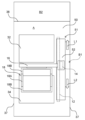
- FIG. Schematic diagram of the second transport mechanism in plan view A schematic perspective view showing a chemical module The figure explaining the movement of the 1st conveyance part in a chemical module.
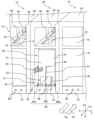
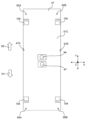
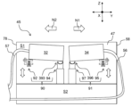
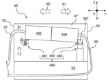
- Schematic diagram of the cleaning tank viewed from the front Schematic enlarged view of the height change part viewed from the side
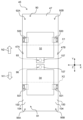
- Schematic enlarged view showing a longitudinal section of the ball part and the ball receiving part Schematic plan view of the sink tank (where the chemical tank and cleaning tank are arranged)
- Schematic plan view of sink tank (without chemical tank and cleaning tank) Schematic enlarged view showing a longitudinal section of a ball portion and a ball receiving portion according to a modification
- module refers to a component that is standardized and detachable (exchangeable), and is handled as a unit when used. means.
- first direction means the direction in which the pair of chemical baths and cleaning baths are arranged, that is, the lateral direction of the substrate processing apparatus 1 (for example, the front-rear direction or the vertical direction).
- second direction is a direction that intersects the first direction and the vertical direction and is a direction in which a plurality of modules are arranged in a row, that is, the longitudinal direction of the substrate processing apparatus 1 (for example, the horizontal direction or the horizontal direction). ).
- the first direction may be called a TD (Transverse Direction) direction
- the second direction may be called an MD (Machine Direction) direction
- first direction is the Y-axis direction
- second direction is the X-axis direction
- vertical direction is the Z-axis direction.
- first direction, the second direction, and the vertical direction intersect each other (for example, are orthogonal).
- FIG. 1 is a perspective view illustrating a substrate processing apparatus 1 according to one embodiment.
- FIG. 2 is a perspective view illustrating constituent elements of the substrate processing apparatus 1 shown in FIG.
- FIG. 3 is a perspective view for explaining the chemical module 7 in the substrate processing apparatus 1 shown in FIG. 1.
- FIG. 4 is a perspective view illustrating the second transfer mechanism 9 in the substrate processing apparatus 1 shown in FIG. 1.
- FIG. 5 is a perspective view for explaining the essential parts of the chemical module 7 shown in FIG.
- FIG. 6 is a perspective view for explaining the unloading module 8 in the substrate processing apparatus 1 shown in FIG. FIG.
- FIG. 7 is a perspective view for explaining the loading module 5 in the substrate processing apparatus 1 shown in FIG. 8A and 8B are diagrams for explaining the movement of the vertical transfer section 13 in the chemical module 7 shown in FIG. 9A and 9B are diagrams for explaining the movement of the first conveying section 11 in the chemical module 7 shown in FIG. 10A and 10B are diagrams illustrating the carrier 2 holding the substrate 4.
- FIG. 11 is a perspective view illustrating the drying module 6 in the substrate processing apparatus 1 shown in FIG. 1.
- the substrate processing apparatus 1 includes at least one module for performing various types of processing on multiple substrates 4 held by the carrier 2 .
- the substrate 4 is, for example, a semiconductor substrate, a glass substrate for a liquid crystal display device, a glass substrate for a photomask, an optical disc substrate, a MEMS sensor substrate, a solar cell panel, or the like.
- the module has a standardized housing 20 and is detachable (exchangeable) in a second direction (the X-axis direction, which is the longitudinal direction of the substrate processing apparatus 1, hereinafter referred to as the "second direction").
- a fan filter unit 24 is arranged on top of the module.
- the fan filter unit 24 has a fan and a filter for taking air in the clean room and sending it out into the module.
- a fan filter unit 24 creates a downflow of clean air into the process space within the module. Instead of arranging the fan filter unit 24, another configuration for taking in clean air in the clean room can be used.
- the substrate processing apparatus 1 includes, for example, a loading module 5, a drying module 6, a chemical module 7 (substrate processing module), a loading module 8, and a second transport mechanism 9.
- the carry-in module 5, the chemical module 7, the drying module 6, and the carry-out module 8 are arranged adjacent to each other along the second direction.
- the loading module 5, the chemical module 7, the drying module 6, and the loading module 8 are configured to be detachably connected in the second direction. As a result, it is possible to respond flexibly to changes in the processing process, and the scalability is enhanced.
- the second transport mechanism 9 extends in the second direction and transports the carrier 2 holding the plurality of substrates 4 shown in FIG. 10 in the second direction.
- the second transport mechanism 9 is arranged in the first direction (Y-axis direction, the lateral direction of the substrate processing apparatus 1) in the loading module 5, the chemical module 7, the drying module 6, and the unloading module 8. 1 direction”).
- the substrate processing apparatus 1 has a control section (not shown).
- the control unit for example, performs operation control and data calculation of each element of the substrate processing apparatus 1 .
- the control unit has, for example, a CPU (Central Processing Unit), a RAM (Random Access Memory), and a ROM (Read Only Memory).
- the CPU executes control according to a program stored in the ROM (for example, control of the transport operation of the carrier 2 by the first transport section 11, the vertical transport section 13, and the second transport section 48).
- the unprocessed substrates 4 are loaded into the apparatus with the carrier 2 as one unit.
- the drying module 6 for example, vapor drying of the substrate 4 with IPA (isopropyl alcohol) or the like is performed with the carrier 2 as one unit.
- the cleaning process of the substrate 4 is performed with the carrier 2 as one unit.
- the carry-out module 8 the substrates 4 after the cleaning process are carried out of the apparatus with the carrier 2 as one unit.
- the loading module 5 is also called a loader section, and is arranged on the upstream side of the substrate processing apparatus 1 in the second direction. As shown in FIG. 7, the loading module 5 has a loading section 26 configured to be openable and closable on the side surface of the casing 20 on the upstream side in the second direction.
- the carrier 2 is loaded into the loading module 5 via the loading section 26 .
- the carrier 2 loaded into the loading module 5 is mounted on the mounting table 22 . Inside the loading module 5 , the carrier 2 is conveyed in the first direction by the first conveying section 11 via the arm 16 , and the carrier 2 is vertically conveyed via the arm 16 . It is performed by the transport unit 13 .
- the first actuator 12 of the first transfer section 11 is arranged laterally below the mounting surface of the mounting table 22 .
- the vertical actuator 14 of the vertical transfer section 13 is also arranged laterally below the mounting surface of the mounting table 22 . That is, the carrier 2 mounted on the mounting table 22 is isolated from the first actuator 12 and the vertical actuator 14 by the downflow from the fan filter unit 24 and the arm length of the arm 16. . As a result, contamination of the carrier 2 inside the loading module 5 by particles generated from the first actuator 12 and the vertical actuator 14 can be suppressed.
- the unloading module 8 is also called an unloader section, and is arranged downstream of the substrate processing apparatus 1 in the second direction. As shown in FIG. 6 , the carrier 2 loaded into the carry-out module 8 is placed on the mounting table 22 . Inside the carry-out module 8 , the carrier 2 is transported in the first direction by the first transport section 11 via the arm 16 , and the carrier 2 is vertically transported via the arm 16 . It is performed by the transport unit 13 .
- the first actuator 12 of the first transfer section 11 is arranged laterally below the mounting surface of the mounting table 22 .
- the vertical actuator 14 of the vertical transfer section 13 is also arranged laterally below the mounting surface of the mounting table 22 .
- the carry-out module 8 has a carry-out section 27 configured to be openable and closable on the side surface of the housing 20 on the downstream side in the second direction.
- the carrier 2 is carried out to the outside of the carry-out module 8 , that is, the outside of the substrate processing apparatus 1 through the carry-out part 27 .
- the carrier 2 is transported in one direction along the second direction from the loading module 5 toward the unloading module 8, but another aspect is also possible.
- the substrate processing apparatus 1 may include only one of the loading module 5 and the unloading module 8, and the loading module 5 has both loader and unloader functions, or the unloading module 8 may function as both a loader and an unloader. can have a function.
- the carrier 2 is transported in both one direction and the other direction along the second direction (that is, transported back and forth along the second direction).
- the substrate processing apparatus 1 has at least one drying module 6.
- the drying module 6 is installed, for example, between the chemical module 7 and the unloading module 8, as shown in FIG.
- the drying module 6 includes, for example, a first transport section 11 that transports the carrier 2 in the first direction and a and a vertical transport section 13 .
- the first transport section 11 has a first actuator 12
- the vertical transport section 13 has a vertical actuator 14 .
- the drying module 6 has a drying chamber 31.
- the drying chamber 31 is arranged, for example, on the front side of the drying module 6 in the first direction.
- a drying process is performed in the drying chamber 31 to dry the substrate 4 after being subjected to various chemical liquid treatments such as cleaning, etching, and resist stripping by the chemical module 7 .
- the carrier 2 holding the substrate 4 is vertically transported to the drying chamber 31 by the vertical transport section 13 via the arm 16 .
- a first actuator 12 and an up/down actuator 14 are arranged at a lateral lower portion of the drying chamber 31 and spaced apart from the drying chamber 31 . Therefore, the drying chamber 31 is isolated from the first actuator 12 and the vertical actuator 14 so as not to be affected.
- a commonly known drying method can be used in this drying treatment.
- a drying method using the Marangoni effect called IMD IPA Mist Dryer
- the carrier 2 holding the substrate 4 is immersed in a pure water tank provided in the drying chamber 31, and IPA mist or vaporized IPA is continuously supplied to the water surface to raise the substrate 4.
- the surface tension difference that occurs on the surface of the substrate 4 passing over the water surface when it is lowered or caused to overflow or downflow the water surface is used.
- drying by centrifugal force called Spin Dryer
- the carrier 2 holding the substrate 4 is set on a rotating rotor provided in the drying chamber 31, and the rotating rotor is rotated after the carrier 2 and the substrate 4 are fixed by a retaining device called a retainer. using the centrifugal force caused by
- drying by steam washing called Vapor Dryer
- the drying chamber 31 is filled with saturated vapor made by heating a solvent with a small latent heat of vaporization (for example, IPA), and the carrier 2 holding the substrate 4 at a temperature lower than the vapor temperature is placed in the drying chamber 31. and wash the surfaces of the carrier 2 and the substrate 4 with IPA that condenses and liquefies on the surface of the substrate 4, and when the carrier 2 and the substrate 4 warm to the same temperature as the IPA vapor, the surfaces of the carrier 2 and the substrate 4 Stop the IPA agglomeration liquefaction into the carrier 2 and the substrate 4 dry.
- IPA solvent with a small latent heat of vaporization
- Still another drying method such as N2 blow drying with N2 can be used.
- the drying chamber 31 is isolated so as not to be affected by the vertical actuator 14 and the first actuator 12 that transport the carrier 2 holding the substrate 4 .
- contamination inside the drying module 6 due to particles generated from the vertical actuator 14 and the first actuator 12 can be suppressed.
- the first actuator 12 and the vertical actuator 14 can also be arranged in the lower part of the rear side of the drying chamber 31 in the first direction, spaced apart from the drying chamber 31 . Further, if only vertical transport is required, the drying module 6 does not need to include the first transport section 11 .
- the chemical module 7 has at least one module.
- the chemical module 7, as shown in FIGS. 1 and 2, has, for example, a first chemical module 7a, a second chemical module 7b, a third chemical module 7c and a fourth chemical module 7d.
- various chemical cleaning such as APM (ammonium hydroxide-hydrogen peroxide mixture) cleaning, SPM (sulfuric acid-hydrogen peroxide mixture) cleaning, HPM (hydrochloric acid-hydrogen peroxide mixture), DHF (diluted hydrofluoric acid) cleaning
- Various chemical treatments such as etching and resist stripping are performed. These chemical treatments can be arbitrarily combined depending on the type of chemical treatment for the substrate 4 .
- Each chemical module 7a, 7b, 7c, 7d is configured to be detachably connected in the second direction. As a result, it is possible to respond flexibly to changes in the processing process, and the scalability is enhanced.
- the chemical module 7 includes a chemical bath 32 (second bath) for chemical cleaning and a cleaning bath 34 (first bath) for pure water cleaning (rinsing).
- the chemical bath 32 is arranged on the rear side in the first direction
- the cleaning bath 34 is arranged on the front side in the first direction. That is, the chemical bath 32 and the cleaning bath 34 are arranged in the first direction.
- the width of the chemical module 7 in the second direction is narrowed, so that the substrate processing apparatus 1 can be miniaturized. It is also possible to adopt a configuration in which the chemical solution tank 32 is arranged on the front side in the first direction and the cleaning tank 34 is arranged on the rear side in the first direction.
- the common exhaust duct 29 for exhausting the chemical vapor generated from the chemical tank 32 can be arranged on the rear side in the first direction, maintenance of the substrate processing apparatus 1 is facilitated.
- Various chemical solutions described above are stored in the chemical solution tank 32 . Pure water is stored in the cleaning tank 34 .
- the chemical bath 32 has, for example, an inner bath in which the carrier 2 is immersed in the chemical and an outer bath in which the chemical overflowing from the upper end of the inner bath is recovered.
- the opening of the chemical tank 32 is closed with a lid at timings not related to the transport operation of the carrier 2 .
- Two side walls 37, 37 are provided on the sides of the chemical bath 32 in the second direction. That is, the side wall 37 partitions the side of the chemical bath 32 in the second direction. As a result, contamination due to the atmosphere of the chemical liquid stored in the chemical liquid tank 32 of the chemical module 7 located next to it can be suppressed.
- a rear wall 38 is provided behind the chemical bath 32 in the first direction. The chemical bath 32 is surrounded by two side walls 37, 37 and a rear wall 38 in a U shape when viewed from above and below.
- two side exhaust ducts 36, 36 having a side exhaust port 36a can be arranged in the lateral upper part of the chemical bath 32, respectively.
- the two side exhaust ports 36a, 36a are positioned slightly lower than the opening of the chemical bath 32, but at approximately the same height.
- the rear wall 38 is provided with a rear exhaust port 39a of a rear exhaust duct 39 (shown in FIG. 9).
- Two side exhaust ducts 36 , 36 and a rear exhaust duct 39 are branched from a common exhaust duct 29 and connected to the common exhaust duct 29 .
- the rear exhaust port 39 a is located above the opening of the chemical bath 32 .
- the side exhaust port 36 a and the rear exhaust port 39 a for exhausting the chemical vapor that evaporates from the chemical tank 32 are arranged around the chemical tank 32 .
- chemical vapor generated from the chemical tank 32 can be prevented from diffusing into the processing space within the chemical module 7, and contamination of the substrates 4 transported in the processing space within the chemical module 7 can be suppressed.
- Each chemical module 7 has a first transport section 11 that transports the carrier 2 in the first direction and a vertical transport section 13 that transports the carrier 2 in the vertical direction.
- the vertical transfer section 13 has a vertical actuator 14 .
- the carrier 2 is supported by a pedestal 18 provided at one end of an inverted U-shaped arm 16 .
- the carrier 2 has the collar portion 3 on its upper portion, and as will be described later, the chuck portion 44 of the second conveying portion 48 enables the gripping of the collar portion 3 in a detachable manner.
- the collar part 3 of the carrier 2 can be configured to be supported by the cradle 18 .
- Arm 16 can also have a D-shape.
- the other end side of the arm 16 is attached to the vertical actuator 14 .
- the vertical actuator 14 is an electric linear actuator, and has, for example, a screw shaft for moving the arm 16, a motor for rotating the screw shaft, a power source, and a control section for controlling the motor.
- the arm 16 is moved downward by the vertical actuator 14 while the carrier 2 is positioned directly above the chemical bath 32 or the cleaning bath 34 , the carrier 2 holding the plurality of substrates 4 moves to the chemical solution of the chemical bath 32 or the cleaning bath 34 . is immersed in the cleaning solution.
- the vertical actuator 14 moves the arm 16 upward while the carrier 2 is immersed in the chemical or cleaning liquid, the carrier 2 holding the plurality of substrates 4 is lifted out of the chemical or cleaning liquid.
- the carrier 2 holding the substrates 4 is moved by the chemical solution or the cleaning solution in the chemical solution tank 32. It is pulled up or immersed in the cleaning liquid in the cleaning tank 34 .
- the first transport section 11 has a first actuator 12 .
- the vertical actuator 14 is attached to the first actuator 12 .
- the first actuator 12 is an electric linear actuator, and has, for example, a screw shaft that moves the vertical actuator 14, a motor that rotates the screw shaft, a power source, and a control unit that controls the motor.
- the carrier 2 holding the plurality of substrates 4 moves directly above the chemical tank 32 and between the cleaning tank 34 . Transported to and from directly above.
- the first actuator 12 and the up/down actuator 14 are arranged outside the opening of the chemical liquid tank 32 with the side exhaust duct 36 interposed therebetween and at the lower side. That is, the downflow from the fan filter unit 24 and the exhaust from the side exhaust duct 36 isolate the chemical solution tank 32 and the cleaning tank 34 from the first actuator 12 and the vertical actuator 14 . As a result, a large separation distance can be secured between the first actuator 12 and the vertical actuator 14 and the opening of the chemical liquid tank 32 , so that particles generated from the first actuator 12 and the vertical actuator 14 can cause damage in the chemical module 7 . contamination can be suppressed. It should be noted that it is also possible to eliminate the two side exhaust ducts 36 and 36 and exhaust only the rear exhaust duct 39 .
- FIG. 1 the second transport mechanism 9 will be described with reference to FIGS. 1, 2, 4, 8 and 9.
- FIG. 1 the second transport mechanism 9 will be described with reference to FIGS. 1, 2, 4, 8 and 9.
- the second transport mechanism 9 is arranged at the upper part of the loading module 5, the chemical module 7, the drying module 6, and the unloading module 8 on the rear side in the first direction.
- the second transport mechanism 9 has, for example, a configuration in which a plurality of second transport housing sections 40 and second actuators 41 are connected in the second direction.
- Each of the second transport/accommodating units 40 is configured as a part of each housing 20 of the loading module 5, the chemical module 7, the drying module 6 and the unloading module 8, for example. That is, the second transporting/accommodating section 40 is configured integrally with the housing 20 . Also, the second transporting/accommodating section 40 can be configured as a separate box-shaped member. In FIGS.
- the second transport/accommodation portion 40 is shown separated from the housing 20.
- 40 may be an integral part forming part of the housing 20, or may be configured as a separate member.
- the second transport housing portion 40 and the second actuator 41 are configured to be detachably connected in the second direction.
- the second transport mechanism 9 has a plurality of second transport accommodation units 40 and at least one second transport unit 48 .
- the number of the second transport units 48 arranged in the second transport mechanism 9 is appropriately increased or decreased according to the number of the second transport housing units 40 to be connected.
- the second transport section 48 has a second actuator 41 .
- the second actuator 41 is housed in the second transport housing section 40 .
- the first actuator 12 and the up/down actuator 14 are accommodated in the chemical module 7 and the second actuator 41 is accommodated in the second transfer/accommodation section 40 . Accordingly, since the first actuator 12 and the vertical actuator 14 and the second actuator 41 are housed separately, contamination within the chemical module 7 can be suppressed.
- the second actuator 41 is, for example, an electric linear actuator.
- the second actuator 41 is, for example, a rack and pinion, and includes a flat guide portion having a geared rack, a circular gear called a pinion, a motor for rotating the circular gear, a power supply, and a motor. and a control unit for controlling the
- the flat plate-shaped guide portion may have a plurality of guide pieces, and the plurality of guide pieces may be detachably connected in the second direction.
- the second conveying section 48 has a rotary actuator 42 connected to the second actuator 41 via a link section 46 .
- the rotary actuator 42 is, for example, an electric rotary actuator, and has a motor that rotates the two rotary arms 43, 43, a power supply, and a control section that controls the motor.
- the rotary actuator 42 can also be a hydraulically or pneumatically driven actuator.
- a rear wall 38 partitions the space between the second actuator 41 and the chemical tank 32 . As a result, contamination within the chemical module 7 caused by the second actuator 41 can be suppressed.
- the rotating arm portion 43 extends in the first direction through an opening 38a formed in the rear wall 38.
- the rotating arm portion 43 can move in the second direction through a gap 37a formed in the side wall 37.
- a chuck portion 44 is provided on the front side of the rotating arm portion 43 .
- the chuck part 44 is configured to be positioned directly above the cleaning tank 34 .
- the chuck part 44 has a U shape when viewed from the side (that is, viewed from the second direction).
- the two chuck portions 44 , 44 grip the collar portion 3 of the carrier 2 by rotating the rotating arm portion 43 and sandwiching the collar portion 3 of the carrier 2 from both sides.
- the grip of the collar portion 3 of the carrier 2 is released. Therefore, the two chuck portions 44 , 44 can be engaged with and disengaged from the collar portion 3 of the carrier 2 .
- the second actuator 41 Since the second actuator 41 is housed in the second transport housing section 40 , the chemical bath 32 and the cleaning bath 34 are isolated from the second actuator 41 so as not to be affected. That is, the second actuator 41 is isolated from the chemical bath 32 and the cleaning bath 34 . As a result, contamination due to particles generated from the second actuator 41 can be suppressed.
- the first actuator 12 and the vertical actuator 14 are arranged on the side lower part (second direction lower part), but may be arranged on the first direction side if necessary.
- the number and combination of modules in the substrate processing apparatus 1 can be appropriately designed as needed.
- the chemical modules 7 and the drying modules 6 can be alternately arranged.
- a substrate processing apparatus 1 includes A chemical module 7 having a chemical bath 32 for treating the substrate 4 held by the carrier 2 with a chemical solution and a cleaning bath 34 for cleaning the substrate 4 held by the carrier 2,
- the chemical module 7 is a first transport unit 11 that transports the carrier 2 in a first direction in which the chemical bath 32 and the cleaning bath 34 are arranged; a vertical transport unit 13 for transporting the carrier 2 in a vertical direction crossing the first direction; a second transport unit 48 for transporting the carrier 2 in a second direction intersecting the first direction and the vertical direction;
- the first transport section 11, the second transport section 48 and the vertical transport section 13 are driven by the first actuator 12, the second actuator 41 and the vertical actuator 14, respectively,
- the first actuator 12 , the second actuator 41 and the vertical actuator 14 are isolated from the chemical bath 32 and the cleaning bath 34 .
- the transport in the first direction by the first transport unit 11 and the transport in the second direction by the second transport unit 48 transport the separate chemical solution tank 32 and the cleaning tank 34 adjacent to each other. Since it is isolated so as not to be affected by the chemical solution adhering to 2, contamination by the chemical solution can be suppressed. Further, since the actuators 12, 41, 14 for driving the transporting units 11, 48, 13 for transporting the carrier 2 are isolated from the chemical bath 32 and the cleaning bath 34 so as not to be affected, the chemical module 7 It is possible to suppress contamination due to particles of the carrier 2 inside. In addition, since the width of the chemical module 7 in the second direction is narrowed by arranging the chemical baths 32 and the cleaning baths 34 in the first direction, the substrate processing apparatus 1 can be miniaturized. In addition, since the equipment for processing each process is modularized, by connecting other modules 5, 6 and 8 to the chemical module 7, it is possible to flexibly respond to changing needs.
- the chemical module 7 is configured to be detachably connected in the second direction.
- the first actuator 12 and the vertical actuator 14 are arranged below the openings of the chemical tank 32 and the cleaning tank 34, respectively.
- a rear wall 38 partitions between the second actuator 41 and the chemical bath 32 .
- a side wall 37 partitions the side of the chemical bath 32 in the second direction.
- the chemical bath 32 is arranged on the rear side in the first direction, and the cleaning bath 34 is arranged on the front side in the first direction.
- the exhaust duct 39 for exhausting the chemical vapor generated from the chemical tank 32 can be arranged on the rear side in the first direction, so maintenance of the substrate processing apparatus 1 is facilitated.
- the present invention is not limited to such a case, and may be carrierless.
- the plurality of substrates 4 may be directly held by the chuck portion 44 or the cradle 18 .
- FIG. 12 is a schematic diagram of the second transport mechanism 9 viewed from above.
- the illustration of the second transport/accommodating section 40 is omitted.
- the second actuator 41 includes an actuator main body 41A and a plurality of rails 41B.
- the actuator body portion 41A is a driving portion that moves in the left-right direction (second direction) along the rail 41B.
- the rail 41B is a member that movably supports the actuator main body 41A, and is provided for each module.
- a plurality of modules are connected by arranging a plurality of rails 41B in the second direction to form a continuous track.
- the actuator main body 41A is a driving part having a motor, reduction part, pinion gear, etc.
- the rail 41B is a rack.
- only one actuator main body 41A is provided for a plurality of rails 41B and is common among a plurality of modules. As a result, the cost for connecting multiple modules can be reduced. It should be noted that the actuator main body 41A is not limited to the case where only one is provided. A plurality of 41A may be provided.
- FIG. 4 Although a plurality of reference numerals 41 are attached in FIG. 4, a plurality of rails 41B of the second actuator 41 exist.
- FIG. 13 is a perspective view showing the chemical module 7 and FIG. 14 is a diagram for explaining the movement of the first conveying section 11 in the chemical module 7.
- FIG. 14 is a diagram for explaining the movement of the first conveying section 11 in the chemical module 7.
- the housing 20 forms a processing space A for processing the substrate 4.
- the processing space A is a space inside which the chemical bath 32 and the cleaning bath 34 are placed, and a plurality of substrates 4 are transported in the front-rear direction (first direction) and lateral direction (second direction).
- Processing space A is surrounded by a pair of side walls 37 and a rear wall 38 .
- the housing 20 forms a first driving space B1.
- the first drive space B1 is a space for arranging the first actuator 12 and the vertical actuator 14 .
- the first driving space B ⁇ b>1 is formed laterally and downwardly in the second direction with respect to the openings of the chemical bath 32 and the cleaning bath 34 .
- the housing 20 forms a second driving space B2.
- the second drive space B2 is a space for arranging the second actuator 41 and the rotary actuator 42 .
- the second driving space B ⁇ b>2 is formed behind the processing space A in the first direction, that is, behind the rear wall 38 .
- the actuators 12, 14, 41, 42 By arranging the actuators 12, 14, 41, 42 in the driving spaces B1, B2, the actuators 12, 14, 41, 42 can be isolated from the processing space A. As a result, foreign matter generated from the actuators 12, 14, 41, and 42 can be prevented from entering the processing space A, and contamination within the chemical module 7 can be prevented.
- the second driving space B2 and the processing space A are separated by a rear wall 38, whereas the first driving space B1 and the processing space A are separated as shown in FIG. , separated by a side exhaust duct 36 .
- the first driving space B1 and the processing space A may be isolated from each other by providing a wall portion that separates the first driving space B1 and the processing space A from each other. An example thereof will be described with reference to FIG.
- FIG. 15 is a schematic plan view showing a processing space A according to a modification.
- a bottom wall 50 is provided so as to surround the chemical tank 32 and the cleaning tank 34 .
- the bottom wall 50 is a wall that forms the bottom of the processing space A.
- An opening 51 is formed in a part of the bottom wall 50 , and a movable wall 52 is provided below the opening 51 .
- the movable wall 52 is arranged to cover the opening 51 and moves in the front-rear direction integrally with the arm 16 that supports the cradle 18 (arrows L1 and L2).
- the movable wall 52 has a shape elongated in the front-rear direction, and has a length that always covers the entire opening 51 within the range in which the arm 16 moves.
- Arm 16 extends downward through movable wall 52 and is connected to vertical actuator 14 .
- the arm 16 is arranged in close contact with the through hole of the movable wall 52 through which the arm 16 passes.
- the side exhaust duct 36 is not provided.
- the processing space A and the first driving space B1 can be physically separated while the arm 16 can be moved in the front-rear direction. can.
- contamination in the chemical module 7 can be suppressed more reliably.
- the rear wall 38 may be provided with a movable wall through which the rotating arm portion 43 is inserted.
- the cradle 18 has an upper step portion 18A and a lower step portion 18B in the outer frame portion forming a space for accommodating the carrier 2.
- the upper step portion 18A is a portion that protrudes upward from the lower step portion 18B, and has a function of supporting the collar portion 3 of the carrier 2 from below.
- the lower step portion 18B is a portion positioned below the upper step portion 18A and forms a gap for arranging the tips of the chuck portions 44 (claw-shaped) of the second conveying portion 48 .
- the chuck portion 44 of the second transport portion 48 supports the flange portion 3 of the carrier 2 at a position different from that of the upper step portion 18A. can do. Thereby, the chuck part 44 and the cradle 18 can hold the carrier 2 without interfering with each other, and the carrier 2 can be easily transferred between the chuck part 44 and the cradle 18 .
- FIGS. 16A to 16L An example of the operation of the substrate processing apparatus 1 will be explained using FIGS. 16A to 16L.
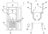
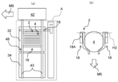
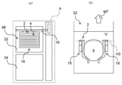
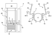
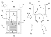
- FIG. 16A to 16L are schematic diagrams for explaining an example of the operation of the substrate processing apparatus 1, (a) showing a plan view of the processing space A, and (b) showing the pedestal 18 and the substrate 4.
- FIG. is a side view showing the peripheral configuration of.
- the cradle 18 stands by above the cleaning tank 34 .
- the cradle 18 is arranged above the cleaning tank 34 and at an intermediate position H1 which is a height position that does not interfere with the chuck portion 44 of the second transfer portion 48 .
- the second transfer section 48 laterally moves the carrier 2 holding the plurality of substrates 4 (arrow M1).
- the second transport section 48 moves the carrier 2 holding the substrate 4 to above the cradle 18 .
- the pedestal 18 is raised from the intermediate position H1 (arrow M2) to hold the carrier 2 on the pedestal 18 .
- the upper stage portion 18A of the cradle 18 is brought into contact with the collar portion 3 of the carrier 2 to support it from below.
- the chuck portion 44 supports the collar portion 3 of the carrier 2 at a position different from the upper step portion 18A of the cradle 18 and does not interfere with the cradle 18 .
- the chuck part 44 is rotated in the opening direction (arrow M3) to release the grip of the substrate 4 .
- the carrier 2 is transferred from the chuck portion 44 to the cradle 18 .
- the cradle 18 holds the carrier 2 at a raised position H2 higher than the intermediate position H1. In this state, the cradle 18 holding the carrier 2 is moved rearward toward the chemical bath 32 (arrow M4). Since the chuck part 44 is open in the direction away from the pedestal 18 , it does not interfere with the movement of the carrier 2 and the pedestal 18 .
- the carrier 2 and the cradle 18 move above the chemical bath 32 and stop.
- the carrier 2 and the pedestal 18 are lowered (arrow M5) to immerse the substrate 4 in the chemical liquid stored in the chemical liquid tank 32 .
- the chuck part 44 of the second transport part 48 is above the cleaning tank 34 and does not interfere with the carrier 2 and the cradle 18, it can be retracted in the lateral direction (arrow M6).
- the second conveying unit 48 may be kept on standby above the cleaning tank 34 without being retracted.
- the cradle 18 descends to a descending position H3, which is the height position at which the substrates 4 are immersed in the chemical solution.
- a descending position H3 which is the height position at which the substrates 4 are immersed in the chemical solution.
- the surface of the substrate 4 can be subjected to processing such as etching.
- any liquid may be used as the chemical liquid in the chemical liquid tank 32 as long as it can treat the surface of the substrate 4 .
- an amine solution such as NMP or monoethanolamine, or acetone may be used.
- SC1 APM
- SC2 HPM
- SPM SPM
- HF hydrofluoric acid
- BHF Buffered hydrofluoric acid
- one liquid may be used alone, or two or more liquids may be used in combination.
- the carrier 2 and the pedestal 18 are raised (arrow M7) to pull up the substrate 4.
- the cradle 18 rises to the intermediate position H1. In this state, the carrier 2 and the cradle 18 are moved forward toward the cleaning tank 34 (arrow M8).
- the carrier 2 and the cradle 18 move above the cleaning tank 34 and stop. After that, the carrier 2 and the pedestal 18 are lowered (arrow M9) to place the substrate 4 inside the cleaning tank 34 .
- the substrate 4 is immersed in cleaning water such as pure water stored in the cleaning tank 34 while the cradle 18 is lowered to the lowered position H3.
- the cleaning water may be sprayed onto the substrate 4 instead of being immersed in the cleaning water.
- any liquid and method may be used as long as the chemical solution adhering to the surface of the substrate 4 can be replaced to the extent that it does not pose a problem in the next treatment.
- protic solvents, water, alcohols such as IPA and ethanol, and amine solutions such as NMP and monoethanolamine may be used.
- one liquid may be used alone, or two or more liquids may be used in combination.
- the retracted second transfer section 48 can be returned to above the cleaning tank 34 (arrow M10). After the chuck part 44 of the second transfer part 48 is positioned above the cleaning tank 34, the carrier 2 and the pedestal 18 holding the substrate 4 that has been rinsed are raised (arrow M11).
- the pedestal 18 rises to the elevated position H2, which is the position for transferring the carrier 2 to the chuck portion 44.
- the chuck part 44 is rotated in the closing direction (arrow M ⁇ b>12 ), and the plurality of substrates 4 are gripped by the chuck part 44 .
- the chuck portion 44 is inserted into the gap between the lower portion 18B of the cradle 18 and the flange portion 3 of the carrier 2 to support the flange portion 3 from below.
- the cradle 18 is lowered while the carrier 2 is held by the chuck portion 44 (arrow M13). As a result, the holding of the carrier 2 by the cradle 18 is released, and the carrier 2 is transferred from the cradle 18 to the chuck portion 44 .
- the cradle 18 is retracted to an intermediate position H1 where it does not interfere with the carrier 2 and the chuck portion 44. Therefore, the second transfer section 48 having the chuck section 44 holding the carrier 2 can move toward the next chemical module 7 (arrow M14).
- the substrate 4 is transported in the front-rear direction using the chemical tanks 32 and the cleaning tanks 34 arranged in the front-rear direction (first direction) in the processing space A of the chemical module 7.
- first transport step the substrate 4 is subjected to the chemical solution treatment and the rinse treatment.
- second transport step By performing the first transfer process and the second transfer process, the substrate 4 that has undergone processing such as etching can be manufactured.
- the operations shown in FIGS. 16A to 16L may be performed for each module on the substrates 4 in one batch.
- the substrate 4 is transported to the next chemical module 7B and another processing is performed (2), and then the next process is performed. Then, the substrate 4 is transported to the chemical module 7C and another process is performed (3).
- the order of the operations (1) to (3) is not particularly limited, and the order may be random. In other words, it is not necessary to transport the substrate 4 in the order in which the chemical modules 7A, 7B, and 7C are arranged and to perform the processing in each module.
- the substrate 4A is processed by the chemical module 7A (4), and another substrate 4B is processed by another chemical module 7B. (5), it is possible to process another substrate 4C in another chemical module 7C (6). Since each of the modules 7A, 7B, and 7C is provided with the first transfer section 11 and the vertical transfer section 13, each of the modules 7A, 7B, and 7C can transfer and process substrates in parallel. Note that the order of operations (4) to (6) is not particularly limited, and may be a random order.
- substrate 4C is transferred to chemical module 7C
- substrate 4A is transferred to chemical module 7A
- substrate 4B is transferred to chemical module 7B
- substrates 4A, 4B, and 4C are transferred in modules 7A, 7B, and 7C. can be processed respectively.
- the chuck portion 44 (not shown) of the second transfer portion 48 moves the substrates 4A and 4B and the carrier 2 ( 17 and 18), it can move laterally through the chemical modules 7A and 7B without interfering with the cradle 18 (7).
- the second transfer section 48 that has moved to the chemical module 7C can receive the substrate 4C for which processing has been completed and transfer it to the next chemical module 7 (8).
- the module (9) moves to the chemical module 7A or 7B where the processing of the substrates 4A or 4B is completed, receives the processed substrate, and then moves to the next module. can be transported to the chemical module 7 of
- a plurality of batches of substrates 4A, 4B, and 4C can be processed in parallel in each module, and the second transport section 48 can be laterally moved across the modules during the processing. .
- the second transport section 48 can be laterally moved across the modules during the processing.
- the chemical module 7 (substrate processing module) of the embodiment includes the cleaning tank 34 (first tank) and the chemical liquid tank 32 (second tank) arranged in the first direction in which the substrates 4 can be placed. , a first transporter 11 that moves the substrate 4 in a first direction, and a second transporter 48 that moves the substrate 4 in a second direction intersecting the first direction.
- the first transport unit 11 transports the substrate 4 in the first direction and the second transport unit 11 transports the substrate 4 in the second direction.
- the substrate 4 can be transferred in different directions (MD direction and TD direction).
- MD direction and TD direction the installation area of the entire apparatus can be reduced.
- the processing efficiency can be improved, such as transporting and processing different substrates 4 by the first transport section 11 and the second transport section 48. can.
- the chemical module 7 of the embodiment further includes a vertical transfer section 13 for moving the substrate 4 up and down.
- the vertical transfer section 13 is connected to the first transfer section 11, and the first transfer section 11 13 is moved in the first direction. According to such a configuration, the function of moving the substrate 4 up and down and the function of moving the substrate 4 in the first direction in the second transfer section 48 can be omitted, and the movement of the substrate 4 can be simplified.
- the chemical module 7 of the embodiment can be connected to another module (the loading module 5, the drying module 6, the chemical module 7, or the unloading module 8) in the second direction.
- substrate 4 can be conveyed between several modules using the 2nd conveyance part 48. As shown in FIG.
- the second actuator 41 of the second transfer section 48 is used in common with another module. With such a configuration, the cost for connecting the chemical module 7 to another module can be reduced.
- the second conveying section 48 includes rails 41B extending in the second direction, and the rails 41B are arranged in line with the rails 41B of another module in the second direction.
- the modules can be connected with each other using a simple structure.
- the chemical module 7 of the embodiment further includes a pair of side walls 37 sandwiching the cleaning tank 34 and the chemical tank 32 in the second direction.
- a gap 37a is formed. According to such a configuration, movement between modules by the second transport section 48 can be realized with a simple configuration. In addition, since the size of the gap 37a can be kept to a size that allows the second conveying portion 48 to pass through, contamination between modules can be suppressed.
- the cleaning tank 34 is arranged on the front side in the first direction
- the chemical liquid tank 32 is arranged on the rear side in the first direction
- the second transfer section 48 is arranged on the substrate 4 is moved above the cleaning tank 34 . According to such a configuration, contamination between the chemical tanks 32 between modules can be reduced. Also, when the operator checks the inside of the chemical module 7 from the front, the substrate 4 transported by the second transport section 48 can be easily visually recognized.
- another module connected to the chemical module 7 in the second direction is any one of the loading module 5, the unloading module 8, the drying module 6, and the chemical module 7. be. According to such a configuration, modules with various functions can be connected as separate modules.
- the substrate processing apparatus 1 of the embodiment includes a chemical module 7 and another module (the loading module 5, the drying module 6, the chemical module 7, or the unloading module 8) connected to the chemical module 7 in the second direction. ). With such a configuration, it is possible to realize the substrate processing apparatus 1 with a small installation area and high processing efficiency.
- the cleaning tank 34 (first tank) and the chemical liquid tank 32 (second tank) are arranged in the first direction. a first transporting step of transporting the substrate 4 in a first direction and a second transporting step of transporting the substrate 4 in a second direction intersecting the first direction so as to move between the substrates;
- the chemical module 7 can transport the substrate 4 in different directions (MD direction and TD direction).
- MD direction and TD direction the installation area of the entire apparatus can be reduced and the processing efficiency can be improved, compared to the conventional substrate processing apparatus in which a plurality of tanks are arranged in only one direction.
- the second transport process may be manually performed by the operator.
- the chemical module 7 (substrate processing module) of the embodiment includes the cleaning tank 34 (first tank) and the chemical liquid tank 32 (second tank) arranged in the first direction in which the substrates 4 can be placed. , a first transport unit 11 for moving the substrate 4 in a first direction, a second transport unit 48 for moving the substrate 4 in a second direction intersecting the first direction, and a first transport unit 11 connected to the substrate 4 . and a vertical transport unit 13 for vertically moving the .
- the first actuator 12 of the first conveying unit 11 and the second actuator 41 of the second conveying unit 48 are located in drive spaces B1 and B2 isolated from the processing space A accessible to the cleaning bath 34 and the chemical bath 32. placed respectively.
- the first transport unit 11 transports the substrate 4 in the first direction and the second transport unit 11 transports the substrate 4 in the second direction.
- the substrate 4 can be transferred in different directions (MD direction and TD direction).
- MD direction and TD direction the installation area of the entire apparatus can be reduced.
- the two actuators 12 and 41 in the drive spaces B1 and B2 isolated from the processing space A, it becomes difficult for foreign matter generated from the actuators 12 and 41 to enter the processing space A. Contamination can be suppressed.
- the first actuator 12 is arranged in the first drive space B1
- the second actuator 41 is arranged in the second drive space B2. According to such a configuration, by arranging the first actuator 12 and the second actuator 41 in the respective driving spaces B1 and B2, it is possible to effectively utilize the space in the module.
- the first driving space B1 is provided on the side and below the openings of the cleaning tank 34 and the chemical liquid tank 32, and the second driving space B2 is provided with respect to the processing space A. is provided rearward in the first direction.
- the chemical module 7 of the embodiment further includes a rear wall 38 provided behind the processing space A, and the second driving space B2 is provided behind the rear wall 38.
- the processing space A and the first driving space B1 are separated by the rear wall 38, so that foreign matter generated from the first actuator arranged in the first driving space B1 is less likely to enter the processing space A. , contamination can be suppressed.
- the rear wall 38 forms an exhaust port 39a for exhausting the atmosphere of the processing space A to the outside. According to such a configuration, even if foreign matter enters the processing space A, it can be exhausted to the outside through the exhaust port 39a.
- the second transfer section 48 includes a rotating arm section 43 (arm) extending forward from the second driving space B2 and passing through an opening 38a provided in the rear wall 38, and a chuck portion 44 that is connected to the rotating arm portion 43 and arranged above the cleaning tank 34 .
- the second conveying section 48 can be realized using a simple configuration.
- the opening 38a of the rear wall 38 only needs to have an area for passing the rotating arm portion 43, by minimizing the area of the opening 38a, foreign matter generated from the second actuator 41 can enter the processing space A. can be made difficult.
- the second drive space B2 can be connected to another module. According to such a configuration, the modules can be easily connected by making the second driving space B2 connectable.
- the second transfer section 48 further includes a rotation actuator 42 that rotates the chuck section 44 for gripping the substrate 4, and the rotation actuator 42 is arranged in the second driving space B2. be done.
- the rotation actuator 42 is arranged in the second driving space B2.
- the vertical actuator 14 of the vertical transfer section 13 is arranged in the first drive space B1. According to such a configuration, by arranging the vertical actuator 14 together with the first actuator 12 in the first drive space B1, it is possible to make it difficult for foreign matter generated from the vertical actuator 14 to enter the processing space A, thereby preventing contamination. can be suppressed.
- the cleaning tank 34 and the chemical liquid tank 32 are provided as two tanks (first tank and second tank)
- the present invention is not limited to such a case.
- different combinations of tanks may be used in each of chemical modules 7A, 7B, and 7C.
- the first tank 34A of the chemical module 7A is a cleaning tank and the second tank 32A is a chemical tank, but both the first tank 34B and the second tank 32B of the chemical module 7B are chemical tanks.
- both the first tank 34C and the second tank 32C of the chemical module 7C are one-bath treatment tanks.
- a one-bath processing tank is a tank that has both chemical processing and cleaning processing functions, and has a function of supplying and draining a chemical solution and a function of supplying and draining a cleaning liquid.
- the chemical solutions used in the first tank 34B and the second tank 32B of the chemical module 7B may be the same or different, and the chemical solutions used in the first tank 34C and the second tank 32C of the chemical module 7C may be the same or different.
- the combination of the first tank and the second tank is not limited to the cleaning tank 34 and the chemical liquid tank 32, and various combinations can be adopted.
- the first tank and the second tank may be any one of a chemical liquid tank, a cleaning tank, and a one-bath treatment tank, and any combination may be adopted.
- each of the first tank and the second tank has the function of chemically treating the substrate 4 with the chemical, the cleaning tank cleaning the substrate 4, and the chemically treating the substrate 4. It is one of the one-bath treatment tanks that also has a cleaning function. According to such a configuration, the first tank and the second tank can be combined in various ways.
- the chemical module 7 of the embodiment is further provided with a substrate processing unit 45 that can be pulled out from the housing 20 in order to improve the maintainability of the chemical bath 32, the cleaning bath 34, and their peripheral members.
- a configuration of the substrate processing unit 45 will be described with reference to FIGS. 20 to 22. FIG.
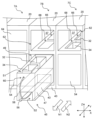
- FIG. 20 is a perspective view of the plurality of chemical modules 7A, 7B, 7C viewed from the front side of the housing 20.
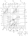
- FIG. 21 and 22 are perspective views of a plurality of chemical modules 7A, 7B, 7C viewed from the rear side of the housing 20.
- FIG. 21 and 22 are perspective views of a plurality of chemical modules 7A, 7B, 7C viewed from the rear side of the housing 20.
- the chemical module 7 has a substrate processing unit 45 that can be pulled out from the housing 20 as a configuration separated from the housing 20 .
- the substrate processing unit 45 has a sink bath 47 containing the chemical bath 32 and the cleaning bath 34 .
- the sink tank 47 including the chemical liquid tank 32 and the cleaning tank 34, is separated from the housing 20 and configured to be pulled out integrally.
- the substrate processing unit 45 of the present embodiment can be pulled out to the front side N1 of the housing 20 and pulled back to the rear side N2 through the opening 49 provided on the front side N1 of the housing 20 .
- the sink tank 47 in addition to the chemical liquid tank 32 and the cleaning tank 34, there are a plurality of pipes 56 and 57 (FIGS. 21 and 22) and other piping-related parts (pump, filter, heater, valve, densitometer, etc.). These members can also be pulled out integrally with the sink tank 47 . Thus, with the sink tank 47 pulled out of the housing 20, maintenance of the chemical tank 32, the cleaning tank 34, and their peripheral members can be performed.
- Other piping-related parts are themselves unitized and can be pulled out integrally with the sink tank 47, and can be pulled out as a single unit separately from the sink tank 47. In other words, it is possible to pull out only other unitized piping-related parts.
- the substrate treatment unit 45 of the chemical module 7 can be replaced with another unit, so that the change of the treatment process can be dealt with flexibly and quickly.
- the sink tank 47 of the chemical module 7B located in the center is pulled out to the front side N1, and the openings of the chemical modules 7A and 7C on both sides are drawn out. 49 exemplifies the closed state with the panel 54 .
- the panel 54 is detachable from the housing 20, and the internal sink tank 47 can be pulled out by removing the panel 54 in the chemical modules 7A and 7C as well.
- the sink tank 47 further has a first accommodation space S1 and a second accommodation space S2 as spaces for accommodating various members.
- the first housing space S1 is a space that houses the chemical bath 32, the cleaning bath 34, and the like.
- the first accommodation space S1 is provided above the sink tank 47, opens upward, and is surrounded by walls on four sides.
- the second housing space S2 is a space for housing the pipe 56 and the like.
- the second accommodation space S2 extends along the Y-axis direction (first direction) below the first accommodation space S1, and extends from the front surface 58 to the rear surface 78 (FIGS. 21 and 22) of the sink tank 47.
- a pipe 56 is a pipe for supplying and discarding a cleaning liquid (for example, pure water) used in the cleaning tank 34 .
- the pipe 56 is inserted through an opening 60 provided in the front surface 58 of the sink tank 47 and connected to the cleaning tank 34 .
- a pipe 56 extending from the cleaning tank 34 and accommodated in the second accommodation space S2 extends toward the rear surface side N2 of the sink tank 47 .
- the opening 62 is an opening that allows visibility and access to the cleaning tank 34 and the chemical tank 32 disposed inside the housing 20 , and is closed by a panel 64 .
- the opening 62 of the chemical module 7A is closed with a panel 64, and the openings 62 of the chemical modules 7B and 7C are opened.
- two tank openings 66 and 68 provided inside the housing 20 are visible and accessible through the opening 62 .
- the tank openings 66 and 68 are openings fixedly formed in the housing 20 so as to expose the chemical liquid tank 32 and the cleaning tank 34, respectively.
- the sink tank 47 containing the chemical tank 32 and the cleaning tank 34 is arranged in the housing 20 as in the chemical module 7C, the chemical tank 32 is exposed at the tank opening 66 and the tank opening 68 is exposed.
- the cleaning tank 34 is exposed.
- the chemical bath 32 and the cleaning bath 34 are separated from the housing 20 through the bath openings 66 and 68 .
- the substrate processing unit 45 that can be pulled out from the housing 20 can be configured. Further, by separating the substrate processing unit 45 from the housing 20, the chemical solution and cleaning liquid generated in the chemical bath 32 and the cleaning bath 34 are less likely to adhere to the housing 20, and corrosion of the housing 20 can be suppressed. The durability of the chemical module 7 can be improved.
- the rear surface side N2 of the housing 20 is provided with two types of openings 70 and 72 and two types of panels 74 and 76.
- the upper opening 70 is an opening that allows visibility and access to the tank openings 66 and 68 and the like, and can be opened and closed by a panel 74 .
- the lower opening 72 is an opening that enables visual confirmation and access to the aforementioned sink tank 47 and the like, and can be opened and closed by a panel 76 .
- the openings 70 of the chemical modules 7A and 7B are opened and the opening 70 of the chemical module 7C is closed with the panel 74 in the upper stage.
- the lower part illustrates a state in which the opening 72 of the chemical module 7B is open and the openings 72 of the chemical modules 7A and 7C are closed with the panel 76.
- a pipe 57 is provided on the rear surface 78 of the sink tank 47 .
- a pipe 57 is a pipe different from the pipe 56 described above, and is connected to the chemical tank 32 .
- the pipe 57 is a pipe for supplying and discarding the chemical used in the chemical tank 32 , and is inserted through an opening 80 provided in the rear surface 78 of the sink tank 47 to be connected to the chemical tank 32 .
- the pipe 57 is not arranged in the second housing space S2 and extends from the rear surface 78 of the sink tank 47 toward the rear surface side N2.
- An exhaust duct 82 is further connected to the rear surface 78 of the sink tank 47 .
- the exhaust duct 82 is a duct for exhausting gas generated inside the sink tank 47 to the outside of the housing 20 .
- the exhaust duct 82 can be attached to an exhaust port 84 fixedly provided in the housing 20 .
- a connection pipe 85 for connecting the exhaust duct 82 to the outside is connected to the exhaust port 84 .
- a plurality of couplers 86 are further provided on the rear surface side N2 of the housing 20.
- the coupler 86 is a connecting portion for connecting the pipes such as the pipes 56 and 57 to the outside (for example, a one-touch coupler).
- a plurality of couplers 86 are attached to a plate portion 87 fixed to the housing 20 .
- FIG. 21 shows the state in which the sink tank 47 is pulled out to the front side N1, and FIG. ).
- the pipes 56 and 57 are both at a position reaching the coupler 86, and the operator attaches the ends of the pipes 56 and 57 to the coupler 86.
- the pipes 56 and 57 are connected to an external supply source, waste port, or the like.
- the exhaust duct 82 and the operator attaches the exhaust duct 82 to the exhaust port 84 to connect the exhaust duct 82 to the outside.
- a rail 88 is further provided inside the housing 20 to allow the sink tank 47 to be pulled out.
- the rail 88 is a member extending along the Y-axis direction (first direction), and in this embodiment, it is composed of three rails 88A, 88B, and 88C.
- the rails 88A and 88B at both ends have, for example, an L-shaped rising shape so as to sandwich the left and right corners of the sink tank 47, and the sink tank 47 is moved while being positioned in the X-axis direction (second direction). .
- the sink tank 47 runs along the rail 88 by pushing the sink tank 47 toward the front side N1. Thereby, the substrate processing unit 45 including the sink tank 47 can be pulled out of the housing 20 . Thus, the substrate processing unit 45 can be easily pulled out.
- the chemical solution tank 32, the cleaning tank 34, and the sink tank 47 are separated from the housing 20, and the sink tank 47 can be pulled out from the housing 20, thereby facilitating maintenance by the operator. can be performed, and the chemical module 7 and the substrate processing unit 45 with improved maintainability can be realized.
- the sink tank 47 can also be pulled out along the Y-axis direction (first direction) while the chemical tank 32 and the cleaning tank 34 are arranged in the Y-axis direction (first direction), thereby providing high maintainability. , the dimension (lateral width) of the chemical module 7 in the X-axis direction can be reduced. As a result, even when a plurality of chemical modules 7 are connected in the X-axis direction, the size of the substrate processing apparatus 1 does not become large, and space saving of the substrate processing apparatus 1 can be achieved.
- the chemical module 7 (substrate processing module) of the embodiment includes the housing 20, the two chemical liquid tanks 32 and the cleaning tank 34 (processing tank) in which the substrates 4 can be placed, respectively, in the Y-axis direction (second
- the sink tank 47 is arranged inside the housing 20, and the sink tank 47, the chemical liquid tank 32, and the cleaning tank 34 are separated from the housing 20. separated.
- the sink tank 47 can be drawn out from the housing 20 , and the chemical liquid tank 32 , the cleaning tank 34 , and other parts housed in the sink tank 47 can be removed from the housing 20 . It can be maintained while it is pulled out. Thereby, high maintainability can be realized.
- a bath including the chemical bath 32 and the cleaning bath 34 that performs arbitrary processing (including chemical processing and cleaning processing) on the substrate 4 is referred to as a “processing bath”.
- the sink tank 47 can be pulled out from the housing 20 along the Y-axis direction (first direction). With such a configuration, the dimension of the chemical module 7 in the X-axis direction can be reduced, and space can be saved.
- the sink tank 47 can be pulled out to the front side N1 of the housing 20. According to such a configuration, maintenance work can be performed on the front side N1 of the sink tank 47, and other work (including attachment and detachment work of the pipes 56 and 57 and the exhaust duct 82) can be performed on the rear side N2 of the housing 20. .)It can be performed.
- the chemical module 7 of the embodiment further has a pipe 56 connected to the cleaning tank 34 (processing tank).
- a second accommodation space S2 is formed to accommodate the pipe 56 extending from. According to such a configuration, in addition to the chemical tank 32 and the cleaning tank 34, other parts such as the pipe 56 can be integrally pulled out for maintenance.
- the second accommodation space S2 is provided below the first accommodation space S1.
- the chemical module 7 of the embodiment further includes a coupler 86 that detachably connects the pipe 56 extending from the second housing space S2.
- a coupler 86 that detachably connects the pipe 56 extending from the second housing space S2.
- the housing 20 has rails 88 for running the sink tank 47 .
- the sink tub 47 can be drawn out using a simple mechanism.
- another chemical module 7 can be connected in the X-axis direction (second direction) intersecting the Y-axis direction (first direction), and the substrate 4 is moved in the Y-axis direction. It further includes a first transporter 11 and a second transporter 48 that moves the substrate 4 in the X-axis direction. According to such a configuration, it is possible to draw out the sink tank 47 from each chemical module 7 while allowing the chemical modules 7 to be connected in the X-axis direction.
- the substrate processing apparatus 1 of the embodiment is connected to the chemical module 7 (substrate processing module) in the X-axis direction (second direction) intersecting the chemical module 7 with the Y-axis direction (first direction). and another chemical module 7 that According to such a configuration, it is possible to realize the substrate processing apparatus 1 with high maintainability while allowing a plurality of chemical modules 7 to be connected.
- the substrate processing unit 45 of the embodiment has the chemical bath 32 and the cleaning bath 34 (two processing baths) in which the substrates 4 can be placed respectively, and the chemical bath 32 and the cleaning bath 34 arranged in the Y-axis direction (first direction).
- the sink tank 47, the chemical tank 32 and the cleaning tank 34 are separated from the housing 20 of the chemical module 7 in which the sink tank 47 is arranged. According to such a configuration, it is possible to achieve the same effect as the chemical module 7 of the embodiment (see paragraph 0157).
- the sink tank 47 can be pulled out from the housing 20 of the chemical module 7 along the Y-axis direction (first direction). With such a configuration, it is possible to reduce the dimension of the substrate processing unit 45 in the X-axis direction, thereby saving space.
- the chemical module 7 of the embodiment further includes a leveling mechanism for leveling the chemical tank 32 and the cleaning tank 34 in order to improve the processing efficiency of the overflow treatment in the chemical tank 32 and the cleaning tank 34 .
- a leveling mechanism will be described with reference to FIGS. 23 to 28. FIG.
- FIGS. 24A and 24B are schematic views of the chemical tank 32 and the cleaning tank 34, respectively. It is a diagram.
- leveling mechanisms 90 and 91 are provided inside the sink tank 47 in the substrate processing unit 45 .
- the leveling mechanism 90 is a mechanism for leveling the chemical bath 32
- the leveling mechanism 91 is a mechanism for leveling the cleaning bath 34 .
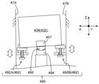
- the leveling mechanism 90 includes a height changing portion 92, a contact portion 93, and a support portion 94.
- the leveling mechanism 91 includes a height changing portion 95 , a contact portion 96 and a support portion 97 .
- Individual components in the leveling mechanisms 90 and 91 have similar structures, and the leveling mechanism 90 will be mainly described below.
- a height changing portion 92 of the leveling mechanism 90 is a member for changing the height of a specific portion in the chemical bath 32 .
- the height changing portion 92 of the present embodiment is provided on the rear surface side N2 of the chemical bath 32 .
- the height changing portion 92 has two height changing portions 92A and 92B spaced apart in the X-axis direction.
- the height changing portion 92A contacts the corner portion 32A of the chemical bath 32 on the left side in the figure
- the height changing portion 92B contacts the corner portion 32B of the chemical solution tank 32 on the right side in the figure.
- the height changing portion 92A is provided on the inner wall surface 47A on one side of the sink tank 47
- the height changing portion 92B is provided on the inner wall surface 47A on the other side of the sink tank 47.
- Height change parts 92A and 92B can change height independently.
- the contact portion 93 is a member provided in the chemical bath 32 and contacts the support portion 94 .
- the contact portion 93 of the present embodiment has a convex spherical surface and is also called a “ball portion”.
- the support portion 94 is a member that contacts the contact portion 93 and supports the contact portion 93 .
- the support portion 94 of this embodiment has a concave spherical surface that receives the contact portion 93, which is a ball portion, and is also referred to as a "ball receiving portion".
- the posture of the chemical bath 32 can be freely adjusted.
- the attitude of the chemical tank 32 can be adjusted in any direction, and the parallelism of the chemical tank 32 can be adjusted. can be maintained with high accuracy.
- the chemical can be easily overflowed evenly from the four sides of the chemical bath 32, and the processing efficiency of the substrate 4 can be improved.
- the leveling work can be performed easily and in a short time because it is only necessary to change the height of the two corners. It is possible to achieve high maintainability.
- the height changing portion 95 has a structure similar to that of the height changing portion 92, and the contact portion 96 has a structure (ball portion) similar to that of the contact portion 93.
- the portion 97 has a structure (ball receiving portion) similar to that of the support portion 94 .
- the contact portion 96 provided in the cleaning tank 34 is received and supported by the support portion 97, and the height of the cleaning tank 34 is changed by the two height changing portions 95A and 95B.
- the posture of the tank 34 can be freely adjusted. As a result, the cleaning liquid can be easily overflowed evenly from the four sides of the cleaning tank 34, and the processing efficiency of the substrates 4 can be improved.
- the height changing portion 92 is provided on the rear side N2, and the contact portion 93 and the support portion 94 are provided on the front side N1.
- the height changing portion 95 is provided on the front side N1, and the contact portion 96 and the support portion 97 are provided on the rear side N2.
- the operator when leveling the chemical liquid tank 32, the operator can access the height changing part 92 from the rear surface 78 of the sink tank 47, and when leveling the cleaning tank 34, the operator can access the sink tank 47
- the height changer 95 can be accessed from the front face 58 of the . Therefore, it is not necessary to access the central portion of the sink tank 47, and the height changing portions 92 and 95 can be easily accessed from the outside of the sink tank 47, thereby facilitating the leveling work.
- FIG. 25 is a schematic enlarged view of the height changer 92 (95) viewed from the side.
- the height changer 92 (95) includes a cradle 100, an adjustment bolt 102, and a guide portion 104.
- the cradle 100 is a plate-like portion for receiving the corners 32A and 32B of the chemical bath 32.
- the cradle 100 is supported by adjusting bolts 102 from below.
- the adjustment bolt 102 is a member for moving the cradle 100 up and down, and is arranged with the head 103 directed downward.
- the adjusting bolt 102 and the cradle 100 supported by the adjusting bolt 102 move up and down integrally (arrow Z1). Thereby, the heights of the corners 32A and 32B of the chemical bath 32 can be changed.
- the adjusting bolt 102 is screwed into the guide portion 104 .
- the guide portion 104 supports the screwed bolt 102 and guides the vertical movement of the cradle 100 .
- the guide portion 104 has a substantially L-shaped cross section and is inserted through a through hole 106 formed in the receiving table 100 .
- the pedestal 100 supported by the adjustment bolt 102 moves up and down while maintaining an engaging relationship with the portion of the guide portion 104 which rises in the vertical direction, thereby moving up and down while maintaining a substantially horizontal state.
- the guide part 104 is fixed to the inner wall surfaces 47A and 47B (FIG. 24A) of the sink tank 47.
- the pedestal 100 and the adjusting bolt 102 are separated from the inner wall surfaces 47A and 47B, and the pedestal 100 on which the chemical tank 32 is mounted is positioned relative to the guide portion 104 and the sink tank 47. Can move up and down.
- FIG. 26 is a schematic enlarged view of a longitudinal section of the contact portion 93 (96) and the support portion 94 (97).
- the chemical bath 32 is provided with an attachment portion 107 for attaching the contact portion 93 .
- the contact portion 93 is attached to the lower surface of the attachment portion 107 .
- the contact portion 93 is a ball portion having a convex spherical surface 108
- the support portion 94 that receives the contact portion 93 is a ball receiving portion having a concave spherical surface 110
- the spherical surfaces 108 and 110 have different radii of curvature.
- the radius of curvature D1 of the spherical surface 108 is set shorter than the radius of curvature D2 of the spherical surface 110 . According to such setting of the radius of curvature, when the convex spherical surface 108 contacts the concave spherical surface 110, the contact point 112 is approximately one point, which is a so-called point contact.
- the point contact between the contact portion 93 and the support portion 94 allows the spherical surface 108 to move smoothly along the spherical surface 110, thereby facilitating the posture adjustment of the chemical tank 32.
- FIG. 27 and 28 are schematic plan views of the sink tank 47 including the chemical tank 32, the cleaning tank 34, and the leveling mechanisms 90 and 91.
- FIG. 27 shows a state in which the chemical liquid tank 32 and the cleaning tank 34 are arranged in the sink tank 47
- FIG. 28 shows a state in which the chemical liquid tank 32 and the cleaning tank 34 are removed from the sink tank 47.
- the chemical bath 32 further has two rod-shaped portions 114.
- the rod-shaped portion 114 is a member fixed to the side surface of the chemical bath 32 and extending in the Y-axis direction in a rod shape.
- One end of each of the rod-shaped portions 114 is received by the cradles 100 of the height changing portions 92A, 92B.
- the posture of the chemical tank 32 can be adjusted by changing the height of the cradle 100 by receiving one end of the rod-shaped portion 114 on the cradle 100 .
- the cleaning tank 34 has two bar-shaped parts 116 .
- the bar-shaped portions 116 are respectively received by the cradles 100 of the height changing portions 95A and 95B, and by changing the height of the cradles 100, the posture of the cleaning tank 34 can be adjusted.
- the mounting portion 107 to which the contact portions 93 and 96 are integrally mounted is provided on the front side N1 of the chemical tank 32, whereas it is provided on the rear side N2 of the cleaning tank . Accordingly, the mounting portion 107 of the chemical tank 32 and the mounting portion 107 of the cleaning tank 34 are arranged adjacent to the central portion of the sink tank 47 .
- the two mounting parts 107 collectively in the central part of the sink tank 47, the height is changed at the end part of the sink tank 47, and there is no need to access the central part of the sink tank 47.
- the space in 47 can be used effectively, and the posture can be easily adjusted.
- the support portions 94 and 97 are provided on the bottom surface 51C of the sink bath 47, and the guide portion 104 is provided inside the sink bath 47. It is provided on the wall surfaces 47A and 47B.
- the cradle 100 and the adjusting bolt 102 are also engaged with the guide portion 104, and the height changing portions 92A, 92B, 95A, and 95B are all provided in the sink tub 47.
- support portions 94 and 97 as ball receiving portions and height changing portions 92 and 95 are provided in the sink tank 47, and contact portions 93 and 96 as ball portions are provided in the chemical liquid tank 32 and the cleaning tank 34. (treatment tank).
- the leveling mechanisms 90 and 91 can be easily installed at the contact points between the chemical bath 32 and the cleaning bath 34 and the sink bath 47 .
- the leveling mechanism 90 for leveling the chemical bath 32 has two height changing portions 92, the contact portion 93, and the support portion 94, and the leveling mechanism 90 for leveling the cleaning bath 34 is provided.
- Mechanism 91 likewise has two height changing portions 95 , contact portion 96 and support portion 97 .
- the chemical module 7 (substrate processing module) of the embodiment includes the housing 20, and the cleaning tanks arranged in the Y-axis direction (first direction) in the housing 20, in which the substrates 4 can be respectively arranged.
- 34 and a chemical bath 32 processing bath
- leveling mechanisms 91 and 90 for leveling the cleaning bath 34 and the chemical bath 32.
- the leveling mechanisms 91 and 90 are provided in the cleaning bath 34 and the chemical bath 32.
- support portions 97 and 94 that contact the contact portions 96 and 93 and receive the contact portions 96 and 93; Height changing portions 95A, 95B, 92A and 92B are respectively provided.
- the contact portions 96 and 93 may be at least partially spherical, and may be entirely spherical, for example. Also, the spherical size is not particularly limited.
- the processing baths include the cleaning bath 34 (first bath) and the chemical solution bath 32 (second bath), and the leveling mechanisms 91 and 90 level the cleaning bath 34. and a leveling mechanism 90 (second leveling mechanism) for leveling the chemical tank 32 .
- the leveling mechanism 91 has a contact portion 96, a support portion 97, and two height changing portions 95A and 95B for changing the height of the cleaning tank 34.
- the leveling mechanism 90 has a contact portion 93 , a support portion 94 , and two height changing portions 92 A and 92 B for changing the height of the chemical bath 32 . According to such a configuration, each of the cleaning tank 34 and the chemical liquid tank 32 can be accurately leveled.
- the cleaning tank 34 is arranged on the front side N1 of the housing 20 with respect to the chemical liquid tank 32, and the height changing part 95 of the leveling mechanism 91 is located on the front side of the cleaning tank 34.
- the height changing part 92 of the leveling mechanism 90 is provided on the rear surface side N2 of the chemical tank 32 .
- another chemical module 7 can be connected in the X-axis direction (second direction) intersecting the Y-axis direction (first direction), and the substrate 4 is moved in the Y-axis direction. It further includes a first transporter 11 and a second transporter 48 that moves the substrate 4 in the X-axis direction. According to such a configuration, while the chemical modules 7 can be connected in the X-axis direction, the leveling mechanisms 90 and 91 in each chemical module 7 can be used to easily level the processing tanks.
- the cleaning tank 34 and the chemical liquid tank 32 are accommodated, and the module is separated from the housing 20 and can be pulled out along the Y-axis direction (first direction) with respect to the housing 20.
- a sink tank 47 is further provided. According to such a configuration, the sink tank 47 can be pulled out, thereby further improving maintainability.
- leveling mechanisms 91 and 90 are provided at contact points between the sink tank 47 and the cleaning tank 34 and the chemical liquid tank 32 (processing tank). With such a configuration, the leveling mechanisms 91 and 90 can be easily installed.
- the support portions 97 and 94 and the height changing portions 95 and 92 are provided in the sink tank 47, and the contact portions 96 and 93 are provided in the cleaning tank 34 and the chemical liquid tank 32 (processing tank). ). With such a configuration, the leveling mechanisms 91 and 90 can be easily installed.
- the contact portions 96 and 93 are partially spherical ball portions, and the support portions 97 and 94 are ball receiving portions for receiving the contact portions 96 and 93 .
- the leveling mechanisms 91 and 90 can be easily installed.
- the substrate processing apparatus 1 of the embodiment is connected to the chemical module 7 (substrate processing module) in the X-axis direction (second direction) intersecting the chemical module 7 with the Y-axis direction (first direction). and another chemical module 7 that According to such a configuration, it is possible to realize the substrate processing apparatus 1 with high maintainability while allowing a plurality of chemical modules 7 to be connected.
- the substrate processing unit 45 of the embodiment has a cleaning bath 34 and a chemical bath 32 (processing bath) in which the substrates 4 can be arranged, and the cleaning bath 34 and the chemical bath 32 are arranged in the Y-axis direction (first direction). and leveling mechanisms 91 and 90 for leveling the cleaning bath 34 and the chemical bath 32.
- the leveling mechanisms 91 and 90 are provided in the cleaning bath 34 and the chemical bath 32. support portions 97 and 94 that contact the contact portions 96 and 93 and receive the contact portions 96 and 93; , and 95A, 95B, 92A, 92B. According to such a configuration, it is possible to achieve the same effect as the chemical module 7 of the embodiment (see paragraph 0196).
- the sink tank 47 is separated from the housing 20 of the chemical module 7 and can be pulled out from the housing 20 .
- Such a configuration contributes to realization of a substrate processing module with high maintainability.
- the shape of the support portions 94 and 97 is not limited thereto. Any shape may be used as long as it can receive the
- a ball receiving portion having a concave polyhedral shape 210 instead of the concave spherical surface may be used.
- the polyhedral shape 210 has a vertical cross section shown in FIG. 29 composed of a plurality of straight lines.
- the support portions 94 and 97 provided in the sink tank 47 are concave ball receiving portions, and the contact portions 93 and 96 provided in the processing tank are convex ball portions.
- the relationship between the ball receiving portion and the ball portion may be reversed.
- the support portions 304 and 307 provided in the sink tank 47 are convex ball portions
- the contact portions 303 and 306 provided in the processing tank are concave ball portions. good too.
- the contact portion 303 provided in the chemical bath 32 receives the support portion 304
- the contact portion 306 provided in the cleaning bath 34 receives the support portion 307 .
- it is sufficient that one of the contact portion and the support portion is an at least partially spherical ball portion and the other is a ball receiving portion that receives the ball portion.
- FIG. 30 exemplifies a form in which the mounting portion 107 described above is omitted and the contact portions 303 and 306 also serve as the mounting portion 107 .
- the attachment portion 107 may be provided and the contact portions 303 and 306 may be attached to the attachment portion 107 as in the embodiment.
- FIG. 31 shows another modified example in which the mounting portion 107 is omitted.
- the contact portion 393 is directly attached to the bottom surface of the chemical bath 32 and the contact portion 396 is directly attached to the bottom surface of the cleaning bath 34 .
- the chemical bath 432 and the cleaning bath 434 may be integrally configured, and the two processing baths may be leveled simultaneously by one leveling mechanism 490.
- the chemical bath 432 and the cleaning bath 434 are integrated, and the leveling mechanism 490 includes a height changing portion 492 , a contact portion 493 and a support portion 494 .
- the height changing portion 492 is provided on the rear side N2 of the chemical bath 432 so as to support one corner of the chemical bath 432, and the contact portion 493 and the support portion 494 are provided on the front side N1 of the cleaning bath 434. be provided. As shown in FIG. 32B, two height changers 492 are provided to support two corners of the chemical bath 432 (height changers 492A and 492B).
- the height changing portion 492 is provided in the chemical bath 432 and the contact portion 493 and the support portion 494 are provided in the cleaning bath 434. may be provided, and the cleaning tank 434 may be provided with two height changing portions.
- height changing portions 92A and 92B are provided at one end (opposite side to the contact portion 93) of the chemical liquid tank 32 in the Y-axis direction to change the height.
- the portions 95A and 95B are provided at one end of the cleaning tank 34 in the Y-axis direction (the side opposite to the contact portion 96)
- the present invention is not limited to such a case.
- a height changer 500 is provided between both ends of the chemical tank 32 in the Y-axis direction, and a height changer 500 is provided between both ends of the cleaning tank 34 in the Y-axis direction.
- a unit 501 may be provided. In the example shown in FIG.
- height changing portions 500 are provided at one end and the other end of the chemical bath 32 in the X-axis direction, respectively, and height changing portions 501 are provided at one end and the other end of the cleaning bath 34 in the X-axis direction, respectively.
- the height changing portion 500 may be arranged on the side opposite to the contact portion 93 (upper side of the drawing) with respect to the center line X1, which is the center position of the chemical bath 32 in the Y-axis direction. It may be arranged on the side opposite to the contact portion 96 (lower side of the drawing) with respect to the center line X2, which is the central position of the tank 34 in the Y-axis direction.
- the position of the chemical bath 32 can be adjusted by changing the height of the chemical bath 32 at two locations using the height changing unit 500, and the height changing unit 501 can be
- the posture of the cleaning tank 34 can be adjusted by changing the height of the cleaning tank 34 at two points using the .
- Rotation arm part 44 Chuck part 46... Link part 48... 2nd conveyance part 45... Substrate processing unit 47... Sink tank 90... Leveling mechanism ( second leveling mechanism) 91... Leveling mechanism (first leveling mechanism) 92, 95... Height change part 93, 96... Contact part (ball part) 94, 97... Support portion (ball receiving portion)
Landscapes
- Cleaning Or Drying Semiconductors (AREA)
Priority Applications (4)
| Application Number | Priority Date | Filing Date | Title |
|---|---|---|---|
| PCT/JP2021/047990 WO2023119584A1 (ja) | 2021-12-23 | 2021-12-23 | 基板処理モジュール、基板処理装置、および基板処理ユニット |
| CN202180105201.6A CN118435322A (zh) | 2021-12-23 | 2021-12-23 | 基板处理模块、基板处理装置以及基板处理单元 |
| JP2023568957A JP7814417B2 (ja) | 2021-12-23 | 2021-12-23 | 基板処理モジュール、基板処理装置、および基板処理ユニット |
| TW111147829A TW202329230A (zh) | 2021-12-23 | 2022-12-13 | 基板處理模組、基板處理裝置及基板處理單元 |
Applications Claiming Priority (1)
| Application Number | Priority Date | Filing Date | Title |
|---|---|---|---|
| PCT/JP2021/047990 WO2023119584A1 (ja) | 2021-12-23 | 2021-12-23 | 基板処理モジュール、基板処理装置、および基板処理ユニット |
Publications (1)
| Publication Number | Publication Date |
|---|---|
| WO2023119584A1 true WO2023119584A1 (ja) | 2023-06-29 |
Family
ID=86901839
Family Applications (1)
| Application Number | Title | Priority Date | Filing Date |
|---|---|---|---|
| PCT/JP2021/047990 Ceased WO2023119584A1 (ja) | 2021-12-23 | 2021-12-23 | 基板処理モジュール、基板処理装置、および基板処理ユニット |
Country Status (4)
| Country | Link |
|---|---|
| JP (1) | JP7814417B2 (https=) |
| CN (1) | CN118435322A (https=) |
| TW (1) | TW202329230A (https=) |
| WO (1) | WO2023119584A1 (https=) |
Citations (6)
| Publication number | Priority date | Publication date | Assignee | Title |
|---|---|---|---|---|
| JPH0521414A (ja) * | 1991-07-13 | 1993-01-29 | Sony Corp | 処理装置 |
| JPH07231018A (ja) * | 1993-08-25 | 1995-08-29 | Tokyo Electron Ltd | プローブ装置 |
| JPH0864570A (ja) * | 1994-08-19 | 1996-03-08 | Hitachi Ltd | ウエハ洗浄装置 |
| JP2000301082A (ja) * | 1999-04-20 | 2000-10-31 | Tokyo Electron Ltd | 処理装置 |
| JP2003213496A (ja) * | 2002-01-22 | 2003-07-30 | Tokyo Electron Ltd | 液処理装置、および液処理方法 |
| JP2016136580A (ja) * | 2015-01-23 | 2016-07-28 | 株式会社荏原製作所 | 基板処理装置、ハウジングおよび処理ユニット |
Family Cites Families (3)
| Publication number | Priority date | Publication date | Assignee | Title |
|---|---|---|---|---|
| JPH0316341U (https=) * | 1989-06-29 | 1991-02-19 | ||
| JPH0817872A (ja) * | 1994-06-24 | 1996-01-19 | Fujitsu Ltd | 部品搭載装置 |
| JPH08170935A (ja) * | 1994-12-19 | 1996-07-02 | Hitachi Ltd | 車体の重心測定装置及び方法 |
-
2021
- 2021-12-23 WO PCT/JP2021/047990 patent/WO2023119584A1/ja not_active Ceased
- 2021-12-23 CN CN202180105201.6A patent/CN118435322A/zh active Pending
- 2021-12-23 JP JP2023568957A patent/JP7814417B2/ja active Active
-
2022
- 2022-12-13 TW TW111147829A patent/TW202329230A/zh unknown
Patent Citations (6)
| Publication number | Priority date | Publication date | Assignee | Title |
|---|---|---|---|---|
| JPH0521414A (ja) * | 1991-07-13 | 1993-01-29 | Sony Corp | 処理装置 |
| JPH07231018A (ja) * | 1993-08-25 | 1995-08-29 | Tokyo Electron Ltd | プローブ装置 |
| JPH0864570A (ja) * | 1994-08-19 | 1996-03-08 | Hitachi Ltd | ウエハ洗浄装置 |
| JP2000301082A (ja) * | 1999-04-20 | 2000-10-31 | Tokyo Electron Ltd | 処理装置 |
| JP2003213496A (ja) * | 2002-01-22 | 2003-07-30 | Tokyo Electron Ltd | 液処理装置、および液処理方法 |
| JP2016136580A (ja) * | 2015-01-23 | 2016-07-28 | 株式会社荏原製作所 | 基板処理装置、ハウジングおよび処理ユニット |
Also Published As
| Publication number | Publication date |
|---|---|
| JPWO2023119584A1 (https=) | 2023-06-29 |
| JP7814417B2 (ja) | 2026-02-16 |
| CN118435322A (zh) | 2024-08-02 |
| TW202329230A (zh) | 2023-07-16 |
Similar Documents
| Publication | Publication Date | Title |
|---|---|---|
| US11462423B2 (en) | Method and apparatus for cleaning semiconductor wafer | |
| JP2000068355A (ja) | 基板処理装置 | |
| KR102320637B1 (ko) | 기판 처리 장치, 캐리어 반송 방법 및 캐리어 버퍼 장치 | |
| CN101409218B (zh) | 单片基底清洁装置和基底背面清洁方法 | |
| TWI729653B (zh) | 基板處理裝置及基板搬送方法 | |
| JP7402983B2 (ja) | 基板処理モジュールおよび基板処理装置、並びに基板の製造方法 | |
| KR20230125752A (ko) | 기판 처리 시스템, 기판 처리 방법 및 기록 매체 | |
| KR20200083286A (ko) | 기판 처리 장치 및 기판 반송 방법 | |
| JP7847157B2 (ja) | 基板処理モジュール、基板処理装置、および基板処理ユニット | |
| WO2023119584A1 (ja) | 基板処理モジュール、基板処理装置、および基板処理ユニット | |
| KR100521401B1 (ko) | 기판세정시스템 | |
| JP2001300445A (ja) | 基板の洗浄装置、洗浄方法および洗浄システム | |
| KR100565433B1 (ko) | 기판이송장치 및 그 장치를 사용한 기판세정시스템 | |
| WO2024203887A1 (ja) | 基板処理モジュールおよび基板処理装置 | |
| JPH11330193A (ja) | 基板処理装置 | |
| KR20100011852A (ko) | 기판세정장치 | |
| KR20090070660A (ko) | 기판 처리 장치 및 이를 이용한 기판 이송 방법 | |
| KR20080066403A (ko) | 기판 이송 방법 |
Legal Events
| Date | Code | Title | Description |
|---|---|---|---|
| 121 | Ep: the epo has been informed by wipo that ep was designated in this application |
Ref document number: 21969019 Country of ref document: EP Kind code of ref document: A1 |
|
| ENP | Entry into the national phase |
Ref document number: 2023568957 Country of ref document: JP Kind code of ref document: A |
|
| WWE | Wipo information: entry into national phase |
Ref document number: 202180105201.6 Country of ref document: CN |
|
| NENP | Non-entry into the national phase |
Ref country code: DE |
|
| 122 | Ep: pct application non-entry in european phase |
Ref document number: 21969019 Country of ref document: EP Kind code of ref document: A1 |