WO2023119584A1 - Substrate processing module, substrate processing device, and substrate processing unit - Google Patents
Substrate processing module, substrate processing device, and substrate processing unit Download PDFInfo
- Publication number
- WO2023119584A1 WO2023119584A1 PCT/JP2021/047990 JP2021047990W WO2023119584A1 WO 2023119584 A1 WO2023119584 A1 WO 2023119584A1 JP 2021047990 W JP2021047990 W JP 2021047990W WO 2023119584 A1 WO2023119584 A1 WO 2023119584A1
- Authority
- WO
- WIPO (PCT)
- Prior art keywords
- chemical
- tank
- module
- substrate processing
- substrate
- Prior art date
Links
Images


Classifications
-
- H—ELECTRICITY
- H01—ELECTRIC ELEMENTS
- H01L—SEMICONDUCTOR DEVICES NOT COVERED BY CLASS H10
- H01L21/00—Processes or apparatus adapted for the manufacture or treatment of semiconductor or solid state devices or of parts thereof
- H01L21/02—Manufacture or treatment of semiconductor devices or of parts thereof
- H01L21/04—Manufacture or treatment of semiconductor devices or of parts thereof the devices having at least one potential-jump barrier or surface barrier, e.g. PN junction, depletion layer or carrier concentration layer
- H01L21/18—Manufacture or treatment of semiconductor devices or of parts thereof the devices having at least one potential-jump barrier or surface barrier, e.g. PN junction, depletion layer or carrier concentration layer the devices having semiconductor bodies comprising elements of Group IV of the Periodic System or AIIIBV compounds with or without impurities, e.g. doping materials
- H01L21/30—Treatment of semiconductor bodies using processes or apparatus not provided for in groups H01L21/20 - H01L21/26
- H01L21/302—Treatment of semiconductor bodies using processes or apparatus not provided for in groups H01L21/20 - H01L21/26 to change their surface-physical characteristics or shape, e.g. etching, polishing, cutting
- H01L21/304—Mechanical treatment, e.g. grinding, polishing, cutting
Definitions
- the present invention relates to a substrate processing module, a substrate processing apparatus, and a substrate processing unit for processing substrates.
- substrate processing apparatus After processing various substrates such as semiconductor wafers (hereinafter referred to as "substrates") with a predetermined chemical solution, they are cleaned with a cleaning liquid such as pure water to remove foreign matter adhering to the surface of the substrates.
- a cleaning liquid such as pure water
- cleaning apparatuses there is a wet-type cleaning apparatus that performs cleaning processing by immersing a substrate in a chemical solution and a cleaning liquid.
- Patent Document 1 discloses a substrate processing apparatus in which a plurality of pairs of chemical liquid tanks and cleaning tanks are arranged in the longitudinal direction of the apparatus, and which has a main transport mechanism and a sub-transport mechanism.
- a main transport mechanism longitudinally moves a plurality of substrates from one end of the apparatus to the other end thereof.
- the sub-transport mechanism moves the plurality of substrates in the longitudinal direction and the vertical direction within the range of the pair of chemical bath and cleaning bath.
- Patent Document 1 since a plurality of pairs of chemical liquid tanks and cleaning tanks are adjacent to each other in the longitudinal direction of the apparatus, the atmosphere of a certain chemical liquid stored in a certain chemical liquid tank causes the adjacent chemical liquid tanks and cleaning tanks to be separated from each other. Contamination of the bath (ie, chemical contamination) occurs. In addition, since the main transport mechanism and sub-transport mechanism face the chemical tank and the cleaning tank, contamination by particles occurs. In addition, since a plurality of pairs of chemical liquid tanks and cleaning tanks are arranged in the longitudinal direction, the apparatus becomes long in the longitudinal direction. In addition, since a plurality of pairs of chemical tanks and cleaning tanks are fixedly installed in the apparatus, it is not possible to flexibly respond to changes in treatment process needs, and maintenance may be difficult.
- an object of the present invention is to provide a substrate processing module, a substrate processing apparatus, and a substrate processing unit that can improve maintainability.
- a substrate processing module includes a housing, two processing tanks arranged in a first direction in the housing and in which substrates can be respectively placed, and a leveling mechanism for performing leveling, the leveling mechanism comprising: a contact portion provided in the processing bath; a support portion that contacts the contact portion and supports the contact portion; and at least two height changers for changing the height.
- a substrate processing apparatus includes the substrate processing module and the another module.
- a substrate processing unit includes two processing baths in which substrates can be placed respectively, a sink bath accommodating the processing baths arranged in a first direction, and leveling of the processing baths. and a leveling mechanism for performing the above-described processing, wherein the leveling mechanism includes a contact portion provided in the processing bath, a support portion that contacts the contact portion and supports the contact portion, and a height of the processing bath. and at least two height changes for changing.
- FIG. 1 is a perspective view illustrating a substrate processing apparatus according to one embodiment
- FIG. FIG. 2 is a perspective view for explaining components of the substrate processing apparatus shown in FIG. 1
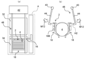
- FIG. 2 is a perspective view for explaining a chemical module in the substrate processing apparatus shown in FIG. 1
- FIG. 2 is a perspective view for explaining a second transport mechanism in the substrate processing apparatus shown in FIG. 1
- FIG. 2 is a perspective view for explaining a carry-out module in the substrate processing apparatus shown in FIG. 1
- 2 is a perspective view for explaining a loading module in the substrate processing apparatus shown in FIG. 1
- FIG. 4A and 4B are diagrams for explaining the movement of the vertical transport section in the chemical module shown in FIG.
- FIGS. 4A and 4B are diagrams for explaining the movement of the first conveying unit in the chemical module shown in FIG. 3;
- a diagram for explaining a carrier that holds a substrate 2 is a perspective view for explaining a drying module in the substrate processing apparatus shown in FIG. 1;
- FIG. Schematic diagram of the second transport mechanism in plan view A schematic perspective view showing a chemical module The figure explaining the movement of the 1st conveyance part in a chemical module.
- Schematic diagram of the cleaning tank viewed from the front Schematic enlarged view of the height change part viewed from the side
- Schematic enlarged view showing a longitudinal section of the ball part and the ball receiving part Schematic plan view of the sink tank (where the chemical tank and cleaning tank are arranged)
- Schematic plan view of sink tank (without chemical tank and cleaning tank) Schematic enlarged view showing a longitudinal section of a ball portion and a ball receiving portion according to a modification
- module refers to a component that is standardized and detachable (exchangeable), and is handled as a unit when used. means.
- first direction means the direction in which the pair of chemical baths and cleaning baths are arranged, that is, the lateral direction of the substrate processing apparatus 1 (for example, the front-rear direction or the vertical direction).
- second direction is a direction that intersects the first direction and the vertical direction and is a direction in which a plurality of modules are arranged in a row, that is, the longitudinal direction of the substrate processing apparatus 1 (for example, the horizontal direction or the horizontal direction). ).
- the first direction may be called a TD (Transverse Direction) direction
- the second direction may be called an MD (Machine Direction) direction
- first direction is the Y-axis direction
- second direction is the X-axis direction
- vertical direction is the Z-axis direction.
- first direction, the second direction, and the vertical direction intersect each other (for example, are orthogonal).
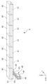
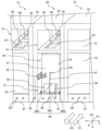
- FIG. 1 is a perspective view illustrating a substrate processing apparatus 1 according to one embodiment.
- FIG. 2 is a perspective view illustrating constituent elements of the substrate processing apparatus 1 shown in FIG.
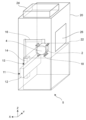
- FIG. 3 is a perspective view for explaining the chemical module 7 in the substrate processing apparatus 1 shown in FIG. 1.
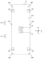
- FIG. 4 is a perspective view illustrating the second transfer mechanism 9 in the substrate processing apparatus 1 shown in FIG. 1.
- FIG. 5 is a perspective view for explaining the essential parts of the chemical module 7 shown in FIG.
- FIG. 6 is a perspective view for explaining the unloading module 8 in the substrate processing apparatus 1 shown in FIG. FIG.
- FIG. 7 is a perspective view for explaining the loading module 5 in the substrate processing apparatus 1 shown in FIG. 8A and 8B are diagrams for explaining the movement of the vertical transfer section 13 in the chemical module 7 shown in FIG. 9A and 9B are diagrams for explaining the movement of the first conveying section 11 in the chemical module 7 shown in FIG. 10A and 10B are diagrams illustrating the carrier 2 holding the substrate 4.
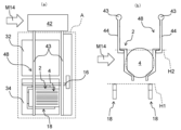
- FIG. 11 is a perspective view illustrating the drying module 6 in the substrate processing apparatus 1 shown in FIG. 1.
- the substrate processing apparatus 1 includes at least one module for performing various types of processing on multiple substrates 4 held by the carrier 2 .
- the substrate 4 is, for example, a semiconductor substrate, a glass substrate for a liquid crystal display device, a glass substrate for a photomask, an optical disc substrate, a MEMS sensor substrate, a solar cell panel, or the like.
- the module has a standardized housing 20 and is detachable (exchangeable) in a second direction (the X-axis direction, which is the longitudinal direction of the substrate processing apparatus 1, hereinafter referred to as the "second direction").
- a fan filter unit 24 is arranged on top of the module.
- the fan filter unit 24 has a fan and a filter for taking air in the clean room and sending it out into the module.
- a fan filter unit 24 creates a downflow of clean air into the process space within the module. Instead of arranging the fan filter unit 24, another configuration for taking in clean air in the clean room can be used.
- the substrate processing apparatus 1 includes, for example, a loading module 5, a drying module 6, a chemical module 7 (substrate processing module), a loading module 8, and a second transport mechanism 9.
- the carry-in module 5, the chemical module 7, the drying module 6, and the carry-out module 8 are arranged adjacent to each other along the second direction.
- the loading module 5, the chemical module 7, the drying module 6, and the loading module 8 are configured to be detachably connected in the second direction. As a result, it is possible to respond flexibly to changes in the processing process, and the scalability is enhanced.
- the second transport mechanism 9 extends in the second direction and transports the carrier 2 holding the plurality of substrates 4 shown in FIG. 10 in the second direction.
- the second transport mechanism 9 is arranged in the first direction (Y-axis direction, the lateral direction of the substrate processing apparatus 1) in the loading module 5, the chemical module 7, the drying module 6, and the unloading module 8. 1 direction”).
- the substrate processing apparatus 1 has a control section (not shown).
- the control unit for example, performs operation control and data calculation of each element of the substrate processing apparatus 1 .
- the control unit has, for example, a CPU (Central Processing Unit), a RAM (Random Access Memory), and a ROM (Read Only Memory).
- the CPU executes control according to a program stored in the ROM (for example, control of the transport operation of the carrier 2 by the first transport section 11, the vertical transport section 13, and the second transport section 48).
- the unprocessed substrates 4 are loaded into the apparatus with the carrier 2 as one unit.
- the drying module 6 for example, vapor drying of the substrate 4 with IPA (isopropyl alcohol) or the like is performed with the carrier 2 as one unit.
- the cleaning process of the substrate 4 is performed with the carrier 2 as one unit.
- the carry-out module 8 the substrates 4 after the cleaning process are carried out of the apparatus with the carrier 2 as one unit.
- the loading module 5 is also called a loader section, and is arranged on the upstream side of the substrate processing apparatus 1 in the second direction. As shown in FIG. 7, the loading module 5 has a loading section 26 configured to be openable and closable on the side surface of the casing 20 on the upstream side in the second direction.
- the carrier 2 is loaded into the loading module 5 via the loading section 26 .
- the carrier 2 loaded into the loading module 5 is mounted on the mounting table 22 . Inside the loading module 5 , the carrier 2 is conveyed in the first direction by the first conveying section 11 via the arm 16 , and the carrier 2 is vertically conveyed via the arm 16 . It is performed by the transport unit 13 .
- the first actuator 12 of the first transfer section 11 is arranged laterally below the mounting surface of the mounting table 22 .
- the vertical actuator 14 of the vertical transfer section 13 is also arranged laterally below the mounting surface of the mounting table 22 . That is, the carrier 2 mounted on the mounting table 22 is isolated from the first actuator 12 and the vertical actuator 14 by the downflow from the fan filter unit 24 and the arm length of the arm 16. . As a result, contamination of the carrier 2 inside the loading module 5 by particles generated from the first actuator 12 and the vertical actuator 14 can be suppressed.
- the unloading module 8 is also called an unloader section, and is arranged downstream of the substrate processing apparatus 1 in the second direction. As shown in FIG. 6 , the carrier 2 loaded into the carry-out module 8 is placed on the mounting table 22 . Inside the carry-out module 8 , the carrier 2 is transported in the first direction by the first transport section 11 via the arm 16 , and the carrier 2 is vertically transported via the arm 16 . It is performed by the transport unit 13 .
- the first actuator 12 of the first transfer section 11 is arranged laterally below the mounting surface of the mounting table 22 .
- the vertical actuator 14 of the vertical transfer section 13 is also arranged laterally below the mounting surface of the mounting table 22 .
- the carry-out module 8 has a carry-out section 27 configured to be openable and closable on the side surface of the housing 20 on the downstream side in the second direction.
- the carrier 2 is carried out to the outside of the carry-out module 8 , that is, the outside of the substrate processing apparatus 1 through the carry-out part 27 .
- the carrier 2 is transported in one direction along the second direction from the loading module 5 toward the unloading module 8, but another aspect is also possible.
- the substrate processing apparatus 1 may include only one of the loading module 5 and the unloading module 8, and the loading module 5 has both loader and unloader functions, or the unloading module 8 may function as both a loader and an unloader. can have a function.
- the carrier 2 is transported in both one direction and the other direction along the second direction (that is, transported back and forth along the second direction).
- the substrate processing apparatus 1 has at least one drying module 6.
- the drying module 6 is installed, for example, between the chemical module 7 and the unloading module 8, as shown in FIG.
- the drying module 6 includes, for example, a first transport section 11 that transports the carrier 2 in the first direction and a and a vertical transport section 13 .
- the first transport section 11 has a first actuator 12
- the vertical transport section 13 has a vertical actuator 14 .
- the drying module 6 has a drying chamber 31.
- the drying chamber 31 is arranged, for example, on the front side of the drying module 6 in the first direction.
- a drying process is performed in the drying chamber 31 to dry the substrate 4 after being subjected to various chemical liquid treatments such as cleaning, etching, and resist stripping by the chemical module 7 .
- the carrier 2 holding the substrate 4 is vertically transported to the drying chamber 31 by the vertical transport section 13 via the arm 16 .
- a first actuator 12 and an up/down actuator 14 are arranged at a lateral lower portion of the drying chamber 31 and spaced apart from the drying chamber 31 . Therefore, the drying chamber 31 is isolated from the first actuator 12 and the vertical actuator 14 so as not to be affected.
- a commonly known drying method can be used in this drying treatment.
- a drying method using the Marangoni effect called IMD IPA Mist Dryer
- the carrier 2 holding the substrate 4 is immersed in a pure water tank provided in the drying chamber 31, and IPA mist or vaporized IPA is continuously supplied to the water surface to raise the substrate 4.
- the surface tension difference that occurs on the surface of the substrate 4 passing over the water surface when it is lowered or caused to overflow or downflow the water surface is used.
- drying by centrifugal force called Spin Dryer
- the carrier 2 holding the substrate 4 is set on a rotating rotor provided in the drying chamber 31, and the rotating rotor is rotated after the carrier 2 and the substrate 4 are fixed by a retaining device called a retainer. using the centrifugal force caused by
- drying by steam washing called Vapor Dryer
- the drying chamber 31 is filled with saturated vapor made by heating a solvent with a small latent heat of vaporization (for example, IPA), and the carrier 2 holding the substrate 4 at a temperature lower than the vapor temperature is placed in the drying chamber 31. and wash the surfaces of the carrier 2 and the substrate 4 with IPA that condenses and liquefies on the surface of the substrate 4, and when the carrier 2 and the substrate 4 warm to the same temperature as the IPA vapor, the surfaces of the carrier 2 and the substrate 4 Stop the IPA agglomeration liquefaction into the carrier 2 and the substrate 4 dry.
- IPA solvent with a small latent heat of vaporization
- Still another drying method such as N2 blow drying with N2 can be used.
- the drying chamber 31 is isolated so as not to be affected by the vertical actuator 14 and the first actuator 12 that transport the carrier 2 holding the substrate 4 .
- contamination inside the drying module 6 due to particles generated from the vertical actuator 14 and the first actuator 12 can be suppressed.
- the first actuator 12 and the vertical actuator 14 can also be arranged in the lower part of the rear side of the drying chamber 31 in the first direction, spaced apart from the drying chamber 31 . Further, if only vertical transport is required, the drying module 6 does not need to include the first transport section 11 .
- the chemical module 7 has at least one module.
- the chemical module 7, as shown in FIGS. 1 and 2, has, for example, a first chemical module 7a, a second chemical module 7b, a third chemical module 7c and a fourth chemical module 7d.
- various chemical cleaning such as APM (ammonium hydroxide-hydrogen peroxide mixture) cleaning, SPM (sulfuric acid-hydrogen peroxide mixture) cleaning, HPM (hydrochloric acid-hydrogen peroxide mixture), DHF (diluted hydrofluoric acid) cleaning
- Various chemical treatments such as etching and resist stripping are performed. These chemical treatments can be arbitrarily combined depending on the type of chemical treatment for the substrate 4 .
- Each chemical module 7a, 7b, 7c, 7d is configured to be detachably connected in the second direction. As a result, it is possible to respond flexibly to changes in the processing process, and the scalability is enhanced.
- the chemical module 7 includes a chemical bath 32 (second bath) for chemical cleaning and a cleaning bath 34 (first bath) for pure water cleaning (rinsing).
- the chemical bath 32 is arranged on the rear side in the first direction
- the cleaning bath 34 is arranged on the front side in the first direction. That is, the chemical bath 32 and the cleaning bath 34 are arranged in the first direction.
- the width of the chemical module 7 in the second direction is narrowed, so that the substrate processing apparatus 1 can be miniaturized. It is also possible to adopt a configuration in which the chemical solution tank 32 is arranged on the front side in the first direction and the cleaning tank 34 is arranged on the rear side in the first direction.
- the common exhaust duct 29 for exhausting the chemical vapor generated from the chemical tank 32 can be arranged on the rear side in the first direction, maintenance of the substrate processing apparatus 1 is facilitated.
- Various chemical solutions described above are stored in the chemical solution tank 32 . Pure water is stored in the cleaning tank 34 .
- the chemical bath 32 has, for example, an inner bath in which the carrier 2 is immersed in the chemical and an outer bath in which the chemical overflowing from the upper end of the inner bath is recovered.
- the opening of the chemical tank 32 is closed with a lid at timings not related to the transport operation of the carrier 2 .
- Two side walls 37, 37 are provided on the sides of the chemical bath 32 in the second direction. That is, the side wall 37 partitions the side of the chemical bath 32 in the second direction. As a result, contamination due to the atmosphere of the chemical liquid stored in the chemical liquid tank 32 of the chemical module 7 located next to it can be suppressed.
- a rear wall 38 is provided behind the chemical bath 32 in the first direction. The chemical bath 32 is surrounded by two side walls 37, 37 and a rear wall 38 in a U shape when viewed from above and below.
- two side exhaust ducts 36, 36 having a side exhaust port 36a can be arranged in the lateral upper part of the chemical bath 32, respectively.
- the two side exhaust ports 36a, 36a are positioned slightly lower than the opening of the chemical bath 32, but at approximately the same height.
- the rear wall 38 is provided with a rear exhaust port 39a of a rear exhaust duct 39 (shown in FIG. 9).
- Two side exhaust ducts 36 , 36 and a rear exhaust duct 39 are branched from a common exhaust duct 29 and connected to the common exhaust duct 29 .
- the rear exhaust port 39 a is located above the opening of the chemical bath 32 .
- the side exhaust port 36 a and the rear exhaust port 39 a for exhausting the chemical vapor that evaporates from the chemical tank 32 are arranged around the chemical tank 32 .
- chemical vapor generated from the chemical tank 32 can be prevented from diffusing into the processing space within the chemical module 7, and contamination of the substrates 4 transported in the processing space within the chemical module 7 can be suppressed.
- Each chemical module 7 has a first transport section 11 that transports the carrier 2 in the first direction and a vertical transport section 13 that transports the carrier 2 in the vertical direction.
- the vertical transfer section 13 has a vertical actuator 14 .
- the carrier 2 is supported by a pedestal 18 provided at one end of an inverted U-shaped arm 16 .
- the carrier 2 has the collar portion 3 on its upper portion, and as will be described later, the chuck portion 44 of the second conveying portion 48 enables the gripping of the collar portion 3 in a detachable manner.
- the collar part 3 of the carrier 2 can be configured to be supported by the cradle 18 .
- Arm 16 can also have a D-shape.
- the other end side of the arm 16 is attached to the vertical actuator 14 .
- the vertical actuator 14 is an electric linear actuator, and has, for example, a screw shaft for moving the arm 16, a motor for rotating the screw shaft, a power source, and a control section for controlling the motor.
- the arm 16 is moved downward by the vertical actuator 14 while the carrier 2 is positioned directly above the chemical bath 32 or the cleaning bath 34 , the carrier 2 holding the plurality of substrates 4 moves to the chemical solution of the chemical bath 32 or the cleaning bath 34 . is immersed in the cleaning solution.
- the vertical actuator 14 moves the arm 16 upward while the carrier 2 is immersed in the chemical or cleaning liquid, the carrier 2 holding the plurality of substrates 4 is lifted out of the chemical or cleaning liquid.
- the carrier 2 holding the substrates 4 is moved by the chemical solution or the cleaning solution in the chemical solution tank 32. It is pulled up or immersed in the cleaning liquid in the cleaning tank 34 .
- the first transport section 11 has a first actuator 12 .
- the vertical actuator 14 is attached to the first actuator 12 .
- the first actuator 12 is an electric linear actuator, and has, for example, a screw shaft that moves the vertical actuator 14, a motor that rotates the screw shaft, a power source, and a control unit that controls the motor.
- the carrier 2 holding the plurality of substrates 4 moves directly above the chemical tank 32 and between the cleaning tank 34 . Transported to and from directly above.
- the first actuator 12 and the up/down actuator 14 are arranged outside the opening of the chemical liquid tank 32 with the side exhaust duct 36 interposed therebetween and at the lower side. That is, the downflow from the fan filter unit 24 and the exhaust from the side exhaust duct 36 isolate the chemical solution tank 32 and the cleaning tank 34 from the first actuator 12 and the vertical actuator 14 . As a result, a large separation distance can be secured between the first actuator 12 and the vertical actuator 14 and the opening of the chemical liquid tank 32 , so that particles generated from the first actuator 12 and the vertical actuator 14 can cause damage in the chemical module 7 . contamination can be suppressed. It should be noted that it is also possible to eliminate the two side exhaust ducts 36 and 36 and exhaust only the rear exhaust duct 39 .
- FIG. 1 the second transport mechanism 9 will be described with reference to FIGS. 1, 2, 4, 8 and 9.
- FIG. 1 the second transport mechanism 9 will be described with reference to FIGS. 1, 2, 4, 8 and 9.
- the second transport mechanism 9 is arranged at the upper part of the loading module 5, the chemical module 7, the drying module 6, and the unloading module 8 on the rear side in the first direction.
- the second transport mechanism 9 has, for example, a configuration in which a plurality of second transport housing sections 40 and second actuators 41 are connected in the second direction.
- Each of the second transport/accommodating units 40 is configured as a part of each housing 20 of the loading module 5, the chemical module 7, the drying module 6 and the unloading module 8, for example. That is, the second transporting/accommodating section 40 is configured integrally with the housing 20 . Also, the second transporting/accommodating section 40 can be configured as a separate box-shaped member. In FIGS.
- the second transport/accommodation portion 40 is shown separated from the housing 20.
- 40 may be an integral part forming part of the housing 20, or may be configured as a separate member.
- the second transport housing portion 40 and the second actuator 41 are configured to be detachably connected in the second direction.
- the second transport mechanism 9 has a plurality of second transport accommodation units 40 and at least one second transport unit 48 .
- the number of the second transport units 48 arranged in the second transport mechanism 9 is appropriately increased or decreased according to the number of the second transport housing units 40 to be connected.
- the second transport section 48 has a second actuator 41 .
- the second actuator 41 is housed in the second transport housing section 40 .
- the first actuator 12 and the up/down actuator 14 are accommodated in the chemical module 7 and the second actuator 41 is accommodated in the second transfer/accommodation section 40 . Accordingly, since the first actuator 12 and the vertical actuator 14 and the second actuator 41 are housed separately, contamination within the chemical module 7 can be suppressed.
- the second actuator 41 is, for example, an electric linear actuator.
- the second actuator 41 is, for example, a rack and pinion, and includes a flat guide portion having a geared rack, a circular gear called a pinion, a motor for rotating the circular gear, a power supply, and a motor. and a control unit for controlling the
- the flat plate-shaped guide portion may have a plurality of guide pieces, and the plurality of guide pieces may be detachably connected in the second direction.
- the second conveying section 48 has a rotary actuator 42 connected to the second actuator 41 via a link section 46 .
- the rotary actuator 42 is, for example, an electric rotary actuator, and has a motor that rotates the two rotary arms 43, 43, a power supply, and a control section that controls the motor.
- the rotary actuator 42 can also be a hydraulically or pneumatically driven actuator.
- a rear wall 38 partitions the space between the second actuator 41 and the chemical tank 32 . As a result, contamination within the chemical module 7 caused by the second actuator 41 can be suppressed.
- the rotating arm portion 43 extends in the first direction through an opening 38a formed in the rear wall 38.
- the rotating arm portion 43 can move in the second direction through a gap 37a formed in the side wall 37.
- a chuck portion 44 is provided on the front side of the rotating arm portion 43 .
- the chuck part 44 is configured to be positioned directly above the cleaning tank 34 .
- the chuck part 44 has a U shape when viewed from the side (that is, viewed from the second direction).
- the two chuck portions 44 , 44 grip the collar portion 3 of the carrier 2 by rotating the rotating arm portion 43 and sandwiching the collar portion 3 of the carrier 2 from both sides.
- the grip of the collar portion 3 of the carrier 2 is released. Therefore, the two chuck portions 44 , 44 can be engaged with and disengaged from the collar portion 3 of the carrier 2 .
- the second actuator 41 Since the second actuator 41 is housed in the second transport housing section 40 , the chemical bath 32 and the cleaning bath 34 are isolated from the second actuator 41 so as not to be affected. That is, the second actuator 41 is isolated from the chemical bath 32 and the cleaning bath 34 . As a result, contamination due to particles generated from the second actuator 41 can be suppressed.
- the first actuator 12 and the vertical actuator 14 are arranged on the side lower part (second direction lower part), but may be arranged on the first direction side if necessary.
- the number and combination of modules in the substrate processing apparatus 1 can be appropriately designed as needed.
- the chemical modules 7 and the drying modules 6 can be alternately arranged.
- a substrate processing apparatus 1 includes A chemical module 7 having a chemical bath 32 for treating the substrate 4 held by the carrier 2 with a chemical solution and a cleaning bath 34 for cleaning the substrate 4 held by the carrier 2,
- the chemical module 7 is a first transport unit 11 that transports the carrier 2 in a first direction in which the chemical bath 32 and the cleaning bath 34 are arranged; a vertical transport unit 13 for transporting the carrier 2 in a vertical direction crossing the first direction; a second transport unit 48 for transporting the carrier 2 in a second direction intersecting the first direction and the vertical direction;
- the first transport section 11, the second transport section 48 and the vertical transport section 13 are driven by the first actuator 12, the second actuator 41 and the vertical actuator 14, respectively,
- the first actuator 12 , the second actuator 41 and the vertical actuator 14 are isolated from the chemical bath 32 and the cleaning bath 34 .
- the transport in the first direction by the first transport unit 11 and the transport in the second direction by the second transport unit 48 transport the separate chemical solution tank 32 and the cleaning tank 34 adjacent to each other. Since it is isolated so as not to be affected by the chemical solution adhering to 2, contamination by the chemical solution can be suppressed. Further, since the actuators 12, 41, 14 for driving the transporting units 11, 48, 13 for transporting the carrier 2 are isolated from the chemical bath 32 and the cleaning bath 34 so as not to be affected, the chemical module 7 It is possible to suppress contamination due to particles of the carrier 2 inside. In addition, since the width of the chemical module 7 in the second direction is narrowed by arranging the chemical baths 32 and the cleaning baths 34 in the first direction, the substrate processing apparatus 1 can be miniaturized. In addition, since the equipment for processing each process is modularized, by connecting other modules 5, 6 and 8 to the chemical module 7, it is possible to flexibly respond to changing needs.
- the chemical module 7 is configured to be detachably connected in the second direction.
- the first actuator 12 and the vertical actuator 14 are arranged below the openings of the chemical tank 32 and the cleaning tank 34, respectively.
- a rear wall 38 partitions between the second actuator 41 and the chemical bath 32 .
- a side wall 37 partitions the side of the chemical bath 32 in the second direction.
- the chemical bath 32 is arranged on the rear side in the first direction, and the cleaning bath 34 is arranged on the front side in the first direction.
- the exhaust duct 39 for exhausting the chemical vapor generated from the chemical tank 32 can be arranged on the rear side in the first direction, so maintenance of the substrate processing apparatus 1 is facilitated.
- the present invention is not limited to such a case, and may be carrierless.
- the plurality of substrates 4 may be directly held by the chuck portion 44 or the cradle 18 .
- FIG. 12 is a schematic diagram of the second transport mechanism 9 viewed from above.
- the illustration of the second transport/accommodating section 40 is omitted.
- the second actuator 41 includes an actuator main body 41A and a plurality of rails 41B.
- the actuator body portion 41A is a driving portion that moves in the left-right direction (second direction) along the rail 41B.
- the rail 41B is a member that movably supports the actuator main body 41A, and is provided for each module.
- a plurality of modules are connected by arranging a plurality of rails 41B in the second direction to form a continuous track.
- the actuator main body 41A is a driving part having a motor, reduction part, pinion gear, etc.
- the rail 41B is a rack.
- only one actuator main body 41A is provided for a plurality of rails 41B and is common among a plurality of modules. As a result, the cost for connecting multiple modules can be reduced. It should be noted that the actuator main body 41A is not limited to the case where only one is provided. A plurality of 41A may be provided.
- FIG. 4 Although a plurality of reference numerals 41 are attached in FIG. 4, a plurality of rails 41B of the second actuator 41 exist.
- FIG. 13 is a perspective view showing the chemical module 7 and FIG. 14 is a diagram for explaining the movement of the first conveying section 11 in the chemical module 7.
- FIG. 14 is a diagram for explaining the movement of the first conveying section 11 in the chemical module 7.
- the housing 20 forms a processing space A for processing the substrate 4.
- the processing space A is a space inside which the chemical bath 32 and the cleaning bath 34 are placed, and a plurality of substrates 4 are transported in the front-rear direction (first direction) and lateral direction (second direction).
- Processing space A is surrounded by a pair of side walls 37 and a rear wall 38 .
- the housing 20 forms a first driving space B1.
- the first drive space B1 is a space for arranging the first actuator 12 and the vertical actuator 14 .
- the first driving space B ⁇ b>1 is formed laterally and downwardly in the second direction with respect to the openings of the chemical bath 32 and the cleaning bath 34 .
- the housing 20 forms a second driving space B2.
- the second drive space B2 is a space for arranging the second actuator 41 and the rotary actuator 42 .
- the second driving space B ⁇ b>2 is formed behind the processing space A in the first direction, that is, behind the rear wall 38 .
- the actuators 12, 14, 41, 42 By arranging the actuators 12, 14, 41, 42 in the driving spaces B1, B2, the actuators 12, 14, 41, 42 can be isolated from the processing space A. As a result, foreign matter generated from the actuators 12, 14, 41, and 42 can be prevented from entering the processing space A, and contamination within the chemical module 7 can be prevented.
- the second driving space B2 and the processing space A are separated by a rear wall 38, whereas the first driving space B1 and the processing space A are separated as shown in FIG. , separated by a side exhaust duct 36 .
- the first driving space B1 and the processing space A may be isolated from each other by providing a wall portion that separates the first driving space B1 and the processing space A from each other. An example thereof will be described with reference to FIG.
- FIG. 15 is a schematic plan view showing a processing space A according to a modification.
- a bottom wall 50 is provided so as to surround the chemical tank 32 and the cleaning tank 34 .
- the bottom wall 50 is a wall that forms the bottom of the processing space A.
- An opening 51 is formed in a part of the bottom wall 50 , and a movable wall 52 is provided below the opening 51 .
- the movable wall 52 is arranged to cover the opening 51 and moves in the front-rear direction integrally with the arm 16 that supports the cradle 18 (arrows L1 and L2).
- the movable wall 52 has a shape elongated in the front-rear direction, and has a length that always covers the entire opening 51 within the range in which the arm 16 moves.
- Arm 16 extends downward through movable wall 52 and is connected to vertical actuator 14 .
- the arm 16 is arranged in close contact with the through hole of the movable wall 52 through which the arm 16 passes.
- the side exhaust duct 36 is not provided.
- the processing space A and the first driving space B1 can be physically separated while the arm 16 can be moved in the front-rear direction. can.
- contamination in the chemical module 7 can be suppressed more reliably.
- the rear wall 38 may be provided with a movable wall through which the rotating arm portion 43 is inserted.
- the cradle 18 has an upper step portion 18A and a lower step portion 18B in the outer frame portion forming a space for accommodating the carrier 2.
- the upper step portion 18A is a portion that protrudes upward from the lower step portion 18B, and has a function of supporting the collar portion 3 of the carrier 2 from below.
- the lower step portion 18B is a portion positioned below the upper step portion 18A and forms a gap for arranging the tips of the chuck portions 44 (claw-shaped) of the second conveying portion 48 .
- the chuck portion 44 of the second transport portion 48 supports the flange portion 3 of the carrier 2 at a position different from that of the upper step portion 18A. can do. Thereby, the chuck part 44 and the cradle 18 can hold the carrier 2 without interfering with each other, and the carrier 2 can be easily transferred between the chuck part 44 and the cradle 18 .
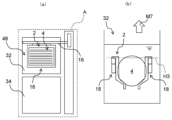
- FIGS. 16A to 16L An example of the operation of the substrate processing apparatus 1 will be explained using FIGS. 16A to 16L.
- FIG. 16A to 16L are schematic diagrams for explaining an example of the operation of the substrate processing apparatus 1, (a) showing a plan view of the processing space A, and (b) showing the pedestal 18 and the substrate 4.
- FIG. is a side view showing the peripheral configuration of.
- the cradle 18 stands by above the cleaning tank 34 .
- the cradle 18 is arranged above the cleaning tank 34 and at an intermediate position H1 which is a height position that does not interfere with the chuck portion 44 of the second transfer portion 48 .
- the second transfer section 48 laterally moves the carrier 2 holding the plurality of substrates 4 (arrow M1).
- the second transport section 48 moves the carrier 2 holding the substrate 4 to above the cradle 18 .
- the pedestal 18 is raised from the intermediate position H1 (arrow M2) to hold the carrier 2 on the pedestal 18 .
- the upper stage portion 18A of the cradle 18 is brought into contact with the collar portion 3 of the carrier 2 to support it from below.
- the chuck portion 44 supports the collar portion 3 of the carrier 2 at a position different from the upper step portion 18A of the cradle 18 and does not interfere with the cradle 18 .
- the chuck part 44 is rotated in the opening direction (arrow M3) to release the grip of the substrate 4 .
- the carrier 2 is transferred from the chuck portion 44 to the cradle 18 .
- the cradle 18 holds the carrier 2 at a raised position H2 higher than the intermediate position H1. In this state, the cradle 18 holding the carrier 2 is moved rearward toward the chemical bath 32 (arrow M4). Since the chuck part 44 is open in the direction away from the pedestal 18 , it does not interfere with the movement of the carrier 2 and the pedestal 18 .
- the carrier 2 and the cradle 18 move above the chemical bath 32 and stop.
- the carrier 2 and the pedestal 18 are lowered (arrow M5) to immerse the substrate 4 in the chemical liquid stored in the chemical liquid tank 32 .
- the chuck part 44 of the second transport part 48 is above the cleaning tank 34 and does not interfere with the carrier 2 and the cradle 18, it can be retracted in the lateral direction (arrow M6).
- the second conveying unit 48 may be kept on standby above the cleaning tank 34 without being retracted.
- the cradle 18 descends to a descending position H3, which is the height position at which the substrates 4 are immersed in the chemical solution.
- a descending position H3 which is the height position at which the substrates 4 are immersed in the chemical solution.
- the surface of the substrate 4 can be subjected to processing such as etching.
- any liquid may be used as the chemical liquid in the chemical liquid tank 32 as long as it can treat the surface of the substrate 4 .
- an amine solution such as NMP or monoethanolamine, or acetone may be used.
- SC1 APM
- SC2 HPM
- SPM SPM
- HF hydrofluoric acid
- BHF Buffered hydrofluoric acid
- one liquid may be used alone, or two or more liquids may be used in combination.
- the carrier 2 and the pedestal 18 are raised (arrow M7) to pull up the substrate 4.
- the cradle 18 rises to the intermediate position H1. In this state, the carrier 2 and the cradle 18 are moved forward toward the cleaning tank 34 (arrow M8).
- the carrier 2 and the cradle 18 move above the cleaning tank 34 and stop. After that, the carrier 2 and the pedestal 18 are lowered (arrow M9) to place the substrate 4 inside the cleaning tank 34 .
- the substrate 4 is immersed in cleaning water such as pure water stored in the cleaning tank 34 while the cradle 18 is lowered to the lowered position H3.
- the cleaning water may be sprayed onto the substrate 4 instead of being immersed in the cleaning water.
- any liquid and method may be used as long as the chemical solution adhering to the surface of the substrate 4 can be replaced to the extent that it does not pose a problem in the next treatment.
- protic solvents, water, alcohols such as IPA and ethanol, and amine solutions such as NMP and monoethanolamine may be used.
- one liquid may be used alone, or two or more liquids may be used in combination.
- the retracted second transfer section 48 can be returned to above the cleaning tank 34 (arrow M10). After the chuck part 44 of the second transfer part 48 is positioned above the cleaning tank 34, the carrier 2 and the pedestal 18 holding the substrate 4 that has been rinsed are raised (arrow M11).
- the pedestal 18 rises to the elevated position H2, which is the position for transferring the carrier 2 to the chuck portion 44.
- the chuck part 44 is rotated in the closing direction (arrow M ⁇ b>12 ), and the plurality of substrates 4 are gripped by the chuck part 44 .
- the chuck portion 44 is inserted into the gap between the lower portion 18B of the cradle 18 and the flange portion 3 of the carrier 2 to support the flange portion 3 from below.
- the cradle 18 is lowered while the carrier 2 is held by the chuck portion 44 (arrow M13). As a result, the holding of the carrier 2 by the cradle 18 is released, and the carrier 2 is transferred from the cradle 18 to the chuck portion 44 .
- the cradle 18 is retracted to an intermediate position H1 where it does not interfere with the carrier 2 and the chuck portion 44. Therefore, the second transfer section 48 having the chuck section 44 holding the carrier 2 can move toward the next chemical module 7 (arrow M14).
- the substrate 4 is transported in the front-rear direction using the chemical tanks 32 and the cleaning tanks 34 arranged in the front-rear direction (first direction) in the processing space A of the chemical module 7.
- first transport step the substrate 4 is subjected to the chemical solution treatment and the rinse treatment.
- second transport step By performing the first transfer process and the second transfer process, the substrate 4 that has undergone processing such as etching can be manufactured.
- the operations shown in FIGS. 16A to 16L may be performed for each module on the substrates 4 in one batch.
- the substrate 4 is transported to the next chemical module 7B and another processing is performed (2), and then the next process is performed. Then, the substrate 4 is transported to the chemical module 7C and another process is performed (3).
- the order of the operations (1) to (3) is not particularly limited, and the order may be random. In other words, it is not necessary to transport the substrate 4 in the order in which the chemical modules 7A, 7B, and 7C are arranged and to perform the processing in each module.
- the substrate 4A is processed by the chemical module 7A (4), and another substrate 4B is processed by another chemical module 7B. (5), it is possible to process another substrate 4C in another chemical module 7C (6). Since each of the modules 7A, 7B, and 7C is provided with the first transfer section 11 and the vertical transfer section 13, each of the modules 7A, 7B, and 7C can transfer and process substrates in parallel. Note that the order of operations (4) to (6) is not particularly limited, and may be a random order.
- substrate 4C is transferred to chemical module 7C
- substrate 4A is transferred to chemical module 7A
- substrate 4B is transferred to chemical module 7B
- substrates 4A, 4B, and 4C are transferred in modules 7A, 7B, and 7C. can be processed respectively.
- the chuck portion 44 (not shown) of the second transfer portion 48 moves the substrates 4A and 4B and the carrier 2 ( 17 and 18), it can move laterally through the chemical modules 7A and 7B without interfering with the cradle 18 (7).
- the second transfer section 48 that has moved to the chemical module 7C can receive the substrate 4C for which processing has been completed and transfer it to the next chemical module 7 (8).
- the module (9) moves to the chemical module 7A or 7B where the processing of the substrates 4A or 4B is completed, receives the processed substrate, and then moves to the next module. can be transported to the chemical module 7 of
- a plurality of batches of substrates 4A, 4B, and 4C can be processed in parallel in each module, and the second transport section 48 can be laterally moved across the modules during the processing. .
- the second transport section 48 can be laterally moved across the modules during the processing.
- the chemical module 7 (substrate processing module) of the embodiment includes the cleaning tank 34 (first tank) and the chemical liquid tank 32 (second tank) arranged in the first direction in which the substrates 4 can be placed. , a first transporter 11 that moves the substrate 4 in a first direction, and a second transporter 48 that moves the substrate 4 in a second direction intersecting the first direction.
- the first transport unit 11 transports the substrate 4 in the first direction and the second transport unit 11 transports the substrate 4 in the second direction.
- the substrate 4 can be transferred in different directions (MD direction and TD direction).
- MD direction and TD direction the installation area of the entire apparatus can be reduced.
- the processing efficiency can be improved, such as transporting and processing different substrates 4 by the first transport section 11 and the second transport section 48. can.
- the chemical module 7 of the embodiment further includes a vertical transfer section 13 for moving the substrate 4 up and down.
- the vertical transfer section 13 is connected to the first transfer section 11, and the first transfer section 11 13 is moved in the first direction. According to such a configuration, the function of moving the substrate 4 up and down and the function of moving the substrate 4 in the first direction in the second transfer section 48 can be omitted, and the movement of the substrate 4 can be simplified.
- the chemical module 7 of the embodiment can be connected to another module (the loading module 5, the drying module 6, the chemical module 7, or the unloading module 8) in the second direction.
- substrate 4 can be conveyed between several modules using the 2nd conveyance part 48. As shown in FIG.
- the second actuator 41 of the second transfer section 48 is used in common with another module. With such a configuration, the cost for connecting the chemical module 7 to another module can be reduced.
- the second conveying section 48 includes rails 41B extending in the second direction, and the rails 41B are arranged in line with the rails 41B of another module in the second direction.
- the modules can be connected with each other using a simple structure.
- the chemical module 7 of the embodiment further includes a pair of side walls 37 sandwiching the cleaning tank 34 and the chemical tank 32 in the second direction.
- a gap 37a is formed. According to such a configuration, movement between modules by the second transport section 48 can be realized with a simple configuration. In addition, since the size of the gap 37a can be kept to a size that allows the second conveying portion 48 to pass through, contamination between modules can be suppressed.
- the cleaning tank 34 is arranged on the front side in the first direction
- the chemical liquid tank 32 is arranged on the rear side in the first direction
- the second transfer section 48 is arranged on the substrate 4 is moved above the cleaning tank 34 . According to such a configuration, contamination between the chemical tanks 32 between modules can be reduced. Also, when the operator checks the inside of the chemical module 7 from the front, the substrate 4 transported by the second transport section 48 can be easily visually recognized.
- another module connected to the chemical module 7 in the second direction is any one of the loading module 5, the unloading module 8, the drying module 6, and the chemical module 7. be. According to such a configuration, modules with various functions can be connected as separate modules.
- the substrate processing apparatus 1 of the embodiment includes a chemical module 7 and another module (the loading module 5, the drying module 6, the chemical module 7, or the unloading module 8) connected to the chemical module 7 in the second direction. ). With such a configuration, it is possible to realize the substrate processing apparatus 1 with a small installation area and high processing efficiency.
- the cleaning tank 34 (first tank) and the chemical liquid tank 32 (second tank) are arranged in the first direction. a first transporting step of transporting the substrate 4 in a first direction and a second transporting step of transporting the substrate 4 in a second direction intersecting the first direction so as to move between the substrates;
- the chemical module 7 can transport the substrate 4 in different directions (MD direction and TD direction).
- MD direction and TD direction the installation area of the entire apparatus can be reduced and the processing efficiency can be improved, compared to the conventional substrate processing apparatus in which a plurality of tanks are arranged in only one direction.
- the second transport process may be manually performed by the operator.
- the chemical module 7 (substrate processing module) of the embodiment includes the cleaning tank 34 (first tank) and the chemical liquid tank 32 (second tank) arranged in the first direction in which the substrates 4 can be placed. , a first transport unit 11 for moving the substrate 4 in a first direction, a second transport unit 48 for moving the substrate 4 in a second direction intersecting the first direction, and a first transport unit 11 connected to the substrate 4 . and a vertical transport unit 13 for vertically moving the .
- the first actuator 12 of the first conveying unit 11 and the second actuator 41 of the second conveying unit 48 are located in drive spaces B1 and B2 isolated from the processing space A accessible to the cleaning bath 34 and the chemical bath 32. placed respectively.
- the first transport unit 11 transports the substrate 4 in the first direction and the second transport unit 11 transports the substrate 4 in the second direction.
- the substrate 4 can be transferred in different directions (MD direction and TD direction).
- MD direction and TD direction the installation area of the entire apparatus can be reduced.
- the two actuators 12 and 41 in the drive spaces B1 and B2 isolated from the processing space A, it becomes difficult for foreign matter generated from the actuators 12 and 41 to enter the processing space A. Contamination can be suppressed.
- the first actuator 12 is arranged in the first drive space B1
- the second actuator 41 is arranged in the second drive space B2. According to such a configuration, by arranging the first actuator 12 and the second actuator 41 in the respective driving spaces B1 and B2, it is possible to effectively utilize the space in the module.
- the first driving space B1 is provided on the side and below the openings of the cleaning tank 34 and the chemical liquid tank 32, and the second driving space B2 is provided with respect to the processing space A. is provided rearward in the first direction.
- the chemical module 7 of the embodiment further includes a rear wall 38 provided behind the processing space A, and the second driving space B2 is provided behind the rear wall 38.
- the processing space A and the first driving space B1 are separated by the rear wall 38, so that foreign matter generated from the first actuator arranged in the first driving space B1 is less likely to enter the processing space A. , contamination can be suppressed.
- the rear wall 38 forms an exhaust port 39a for exhausting the atmosphere of the processing space A to the outside. According to such a configuration, even if foreign matter enters the processing space A, it can be exhausted to the outside through the exhaust port 39a.
- the second transfer section 48 includes a rotating arm section 43 (arm) extending forward from the second driving space B2 and passing through an opening 38a provided in the rear wall 38, and a chuck portion 44 that is connected to the rotating arm portion 43 and arranged above the cleaning tank 34 .
- the second conveying section 48 can be realized using a simple configuration.
- the opening 38a of the rear wall 38 only needs to have an area for passing the rotating arm portion 43, by minimizing the area of the opening 38a, foreign matter generated from the second actuator 41 can enter the processing space A. can be made difficult.
- the second drive space B2 can be connected to another module. According to such a configuration, the modules can be easily connected by making the second driving space B2 connectable.
- the second transfer section 48 further includes a rotation actuator 42 that rotates the chuck section 44 for gripping the substrate 4, and the rotation actuator 42 is arranged in the second driving space B2. be done.
- the rotation actuator 42 is arranged in the second driving space B2.
- the vertical actuator 14 of the vertical transfer section 13 is arranged in the first drive space B1. According to such a configuration, by arranging the vertical actuator 14 together with the first actuator 12 in the first drive space B1, it is possible to make it difficult for foreign matter generated from the vertical actuator 14 to enter the processing space A, thereby preventing contamination. can be suppressed.
- the cleaning tank 34 and the chemical liquid tank 32 are provided as two tanks (first tank and second tank)
- the present invention is not limited to such a case.
- different combinations of tanks may be used in each of chemical modules 7A, 7B, and 7C.
- the first tank 34A of the chemical module 7A is a cleaning tank and the second tank 32A is a chemical tank, but both the first tank 34B and the second tank 32B of the chemical module 7B are chemical tanks.
- both the first tank 34C and the second tank 32C of the chemical module 7C are one-bath treatment tanks.
- a one-bath processing tank is a tank that has both chemical processing and cleaning processing functions, and has a function of supplying and draining a chemical solution and a function of supplying and draining a cleaning liquid.
- the chemical solutions used in the first tank 34B and the second tank 32B of the chemical module 7B may be the same or different, and the chemical solutions used in the first tank 34C and the second tank 32C of the chemical module 7C may be the same or different.
- the combination of the first tank and the second tank is not limited to the cleaning tank 34 and the chemical liquid tank 32, and various combinations can be adopted.
- the first tank and the second tank may be any one of a chemical liquid tank, a cleaning tank, and a one-bath treatment tank, and any combination may be adopted.
- each of the first tank and the second tank has the function of chemically treating the substrate 4 with the chemical, the cleaning tank cleaning the substrate 4, and the chemically treating the substrate 4. It is one of the one-bath treatment tanks that also has a cleaning function. According to such a configuration, the first tank and the second tank can be combined in various ways.
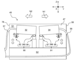
- the chemical module 7 of the embodiment is further provided with a substrate processing unit 45 that can be pulled out from the housing 20 in order to improve the maintainability of the chemical bath 32, the cleaning bath 34, and their peripheral members.
- a configuration of the substrate processing unit 45 will be described with reference to FIGS. 20 to 22. FIG.
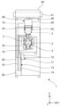
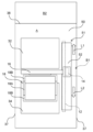
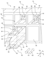
- FIG. 20 is a perspective view of the plurality of chemical modules 7A, 7B, 7C viewed from the front side of the housing 20.
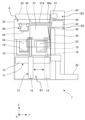
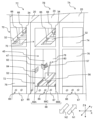
- FIG. 21 and 22 are perspective views of a plurality of chemical modules 7A, 7B, 7C viewed from the rear side of the housing 20.
- FIG. 21 and 22 are perspective views of a plurality of chemical modules 7A, 7B, 7C viewed from the rear side of the housing 20.
- the chemical module 7 has a substrate processing unit 45 that can be pulled out from the housing 20 as a configuration separated from the housing 20 .
- the substrate processing unit 45 has a sink bath 47 containing the chemical bath 32 and the cleaning bath 34 .
- the sink tank 47 including the chemical liquid tank 32 and the cleaning tank 34, is separated from the housing 20 and configured to be pulled out integrally.
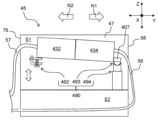
- the substrate processing unit 45 of the present embodiment can be pulled out to the front side N1 of the housing 20 and pulled back to the rear side N2 through the opening 49 provided on the front side N1 of the housing 20 .
- the sink tank 47 in addition to the chemical liquid tank 32 and the cleaning tank 34, there are a plurality of pipes 56 and 57 (FIGS. 21 and 22) and other piping-related parts (pump, filter, heater, valve, densitometer, etc.). These members can also be pulled out integrally with the sink tank 47 . Thus, with the sink tank 47 pulled out of the housing 20, maintenance of the chemical tank 32, the cleaning tank 34, and their peripheral members can be performed.
- Other piping-related parts are themselves unitized and can be pulled out integrally with the sink tank 47, and can be pulled out as a single unit separately from the sink tank 47. In other words, it is possible to pull out only other unitized piping-related parts.
- the substrate treatment unit 45 of the chemical module 7 can be replaced with another unit, so that the change of the treatment process can be dealt with flexibly and quickly.
- the sink tank 47 of the chemical module 7B located in the center is pulled out to the front side N1, and the openings of the chemical modules 7A and 7C on both sides are drawn out. 49 exemplifies the closed state with the panel 54 .
- the panel 54 is detachable from the housing 20, and the internal sink tank 47 can be pulled out by removing the panel 54 in the chemical modules 7A and 7C as well.
- the sink tank 47 further has a first accommodation space S1 and a second accommodation space S2 as spaces for accommodating various members.
- the first housing space S1 is a space that houses the chemical bath 32, the cleaning bath 34, and the like.
- the first accommodation space S1 is provided above the sink tank 47, opens upward, and is surrounded by walls on four sides.
- the second housing space S2 is a space for housing the pipe 56 and the like.
- the second accommodation space S2 extends along the Y-axis direction (first direction) below the first accommodation space S1, and extends from the front surface 58 to the rear surface 78 (FIGS. 21 and 22) of the sink tank 47.
- a pipe 56 is a pipe for supplying and discarding a cleaning liquid (for example, pure water) used in the cleaning tank 34 .
- the pipe 56 is inserted through an opening 60 provided in the front surface 58 of the sink tank 47 and connected to the cleaning tank 34 .
- a pipe 56 extending from the cleaning tank 34 and accommodated in the second accommodation space S2 extends toward the rear surface side N2 of the sink tank 47 .
- the opening 62 is an opening that allows visibility and access to the cleaning tank 34 and the chemical tank 32 disposed inside the housing 20 , and is closed by a panel 64 .
- the opening 62 of the chemical module 7A is closed with a panel 64, and the openings 62 of the chemical modules 7B and 7C are opened.
- two tank openings 66 and 68 provided inside the housing 20 are visible and accessible through the opening 62 .
- the tank openings 66 and 68 are openings fixedly formed in the housing 20 so as to expose the chemical liquid tank 32 and the cleaning tank 34, respectively.
- the sink tank 47 containing the chemical tank 32 and the cleaning tank 34 is arranged in the housing 20 as in the chemical module 7C, the chemical tank 32 is exposed at the tank opening 66 and the tank opening 68 is exposed.
- the cleaning tank 34 is exposed.
- the chemical bath 32 and the cleaning bath 34 are separated from the housing 20 through the bath openings 66 and 68 .
- the substrate processing unit 45 that can be pulled out from the housing 20 can be configured. Further, by separating the substrate processing unit 45 from the housing 20, the chemical solution and cleaning liquid generated in the chemical bath 32 and the cleaning bath 34 are less likely to adhere to the housing 20, and corrosion of the housing 20 can be suppressed. The durability of the chemical module 7 can be improved.
- the rear surface side N2 of the housing 20 is provided with two types of openings 70 and 72 and two types of panels 74 and 76.
- the upper opening 70 is an opening that allows visibility and access to the tank openings 66 and 68 and the like, and can be opened and closed by a panel 74 .
- the lower opening 72 is an opening that enables visual confirmation and access to the aforementioned sink tank 47 and the like, and can be opened and closed by a panel 76 .
- the openings 70 of the chemical modules 7A and 7B are opened and the opening 70 of the chemical module 7C is closed with the panel 74 in the upper stage.
- the lower part illustrates a state in which the opening 72 of the chemical module 7B is open and the openings 72 of the chemical modules 7A and 7C are closed with the panel 76.
- a pipe 57 is provided on the rear surface 78 of the sink tank 47 .
- a pipe 57 is a pipe different from the pipe 56 described above, and is connected to the chemical tank 32 .
- the pipe 57 is a pipe for supplying and discarding the chemical used in the chemical tank 32 , and is inserted through an opening 80 provided in the rear surface 78 of the sink tank 47 to be connected to the chemical tank 32 .
- the pipe 57 is not arranged in the second housing space S2 and extends from the rear surface 78 of the sink tank 47 toward the rear surface side N2.
- An exhaust duct 82 is further connected to the rear surface 78 of the sink tank 47 .
- the exhaust duct 82 is a duct for exhausting gas generated inside the sink tank 47 to the outside of the housing 20 .
- the exhaust duct 82 can be attached to an exhaust port 84 fixedly provided in the housing 20 .
- a connection pipe 85 for connecting the exhaust duct 82 to the outside is connected to the exhaust port 84 .
- a plurality of couplers 86 are further provided on the rear surface side N2 of the housing 20.
- the coupler 86 is a connecting portion for connecting the pipes such as the pipes 56 and 57 to the outside (for example, a one-touch coupler).
- a plurality of couplers 86 are attached to a plate portion 87 fixed to the housing 20 .
- FIG. 21 shows the state in which the sink tank 47 is pulled out to the front side N1, and FIG. ).
- the pipes 56 and 57 are both at a position reaching the coupler 86, and the operator attaches the ends of the pipes 56 and 57 to the coupler 86.
- the pipes 56 and 57 are connected to an external supply source, waste port, or the like.
- the exhaust duct 82 and the operator attaches the exhaust duct 82 to the exhaust port 84 to connect the exhaust duct 82 to the outside.
- a rail 88 is further provided inside the housing 20 to allow the sink tank 47 to be pulled out.
- the rail 88 is a member extending along the Y-axis direction (first direction), and in this embodiment, it is composed of three rails 88A, 88B, and 88C.
- the rails 88A and 88B at both ends have, for example, an L-shaped rising shape so as to sandwich the left and right corners of the sink tank 47, and the sink tank 47 is moved while being positioned in the X-axis direction (second direction). .
- the sink tank 47 runs along the rail 88 by pushing the sink tank 47 toward the front side N1. Thereby, the substrate processing unit 45 including the sink tank 47 can be pulled out of the housing 20 . Thus, the substrate processing unit 45 can be easily pulled out.
- the chemical solution tank 32, the cleaning tank 34, and the sink tank 47 are separated from the housing 20, and the sink tank 47 can be pulled out from the housing 20, thereby facilitating maintenance by the operator. can be performed, and the chemical module 7 and the substrate processing unit 45 with improved maintainability can be realized.
- the sink tank 47 can also be pulled out along the Y-axis direction (first direction) while the chemical tank 32 and the cleaning tank 34 are arranged in the Y-axis direction (first direction), thereby providing high maintainability. , the dimension (lateral width) of the chemical module 7 in the X-axis direction can be reduced. As a result, even when a plurality of chemical modules 7 are connected in the X-axis direction, the size of the substrate processing apparatus 1 does not become large, and space saving of the substrate processing apparatus 1 can be achieved.
- the chemical module 7 (substrate processing module) of the embodiment includes the housing 20, the two chemical liquid tanks 32 and the cleaning tank 34 (processing tank) in which the substrates 4 can be placed, respectively, in the Y-axis direction (second
- the sink tank 47 is arranged inside the housing 20, and the sink tank 47, the chemical liquid tank 32, and the cleaning tank 34 are separated from the housing 20. separated.
- the sink tank 47 can be drawn out from the housing 20 , and the chemical liquid tank 32 , the cleaning tank 34 , and other parts housed in the sink tank 47 can be removed from the housing 20 . It can be maintained while it is pulled out. Thereby, high maintainability can be realized.
- a bath including the chemical bath 32 and the cleaning bath 34 that performs arbitrary processing (including chemical processing and cleaning processing) on the substrate 4 is referred to as a “processing bath”.
- the sink tank 47 can be pulled out from the housing 20 along the Y-axis direction (first direction). With such a configuration, the dimension of the chemical module 7 in the X-axis direction can be reduced, and space can be saved.
- the sink tank 47 can be pulled out to the front side N1 of the housing 20. According to such a configuration, maintenance work can be performed on the front side N1 of the sink tank 47, and other work (including attachment and detachment work of the pipes 56 and 57 and the exhaust duct 82) can be performed on the rear side N2 of the housing 20. .)It can be performed.
- the chemical module 7 of the embodiment further has a pipe 56 connected to the cleaning tank 34 (processing tank).
- a second accommodation space S2 is formed to accommodate the pipe 56 extending from. According to such a configuration, in addition to the chemical tank 32 and the cleaning tank 34, other parts such as the pipe 56 can be integrally pulled out for maintenance.
- the second accommodation space S2 is provided below the first accommodation space S1.
- the chemical module 7 of the embodiment further includes a coupler 86 that detachably connects the pipe 56 extending from the second housing space S2.
- a coupler 86 that detachably connects the pipe 56 extending from the second housing space S2.
- the housing 20 has rails 88 for running the sink tank 47 .
- the sink tub 47 can be drawn out using a simple mechanism.
- another chemical module 7 can be connected in the X-axis direction (second direction) intersecting the Y-axis direction (first direction), and the substrate 4 is moved in the Y-axis direction. It further includes a first transporter 11 and a second transporter 48 that moves the substrate 4 in the X-axis direction. According to such a configuration, it is possible to draw out the sink tank 47 from each chemical module 7 while allowing the chemical modules 7 to be connected in the X-axis direction.
- the substrate processing apparatus 1 of the embodiment is connected to the chemical module 7 (substrate processing module) in the X-axis direction (second direction) intersecting the chemical module 7 with the Y-axis direction (first direction). and another chemical module 7 that According to such a configuration, it is possible to realize the substrate processing apparatus 1 with high maintainability while allowing a plurality of chemical modules 7 to be connected.
- the substrate processing unit 45 of the embodiment has the chemical bath 32 and the cleaning bath 34 (two processing baths) in which the substrates 4 can be placed respectively, and the chemical bath 32 and the cleaning bath 34 arranged in the Y-axis direction (first direction).
- the sink tank 47, the chemical tank 32 and the cleaning tank 34 are separated from the housing 20 of the chemical module 7 in which the sink tank 47 is arranged. According to such a configuration, it is possible to achieve the same effect as the chemical module 7 of the embodiment (see paragraph 0157).
- the sink tank 47 can be pulled out from the housing 20 of the chemical module 7 along the Y-axis direction (first direction). With such a configuration, it is possible to reduce the dimension of the substrate processing unit 45 in the X-axis direction, thereby saving space.
- the chemical module 7 of the embodiment further includes a leveling mechanism for leveling the chemical tank 32 and the cleaning tank 34 in order to improve the processing efficiency of the overflow treatment in the chemical tank 32 and the cleaning tank 34 .
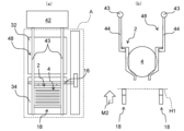
- a leveling mechanism will be described with reference to FIGS. 23 to 28. FIG.
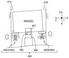
- FIGS. 24A and 24B are schematic views of the chemical tank 32 and the cleaning tank 34, respectively. It is a diagram.
- leveling mechanisms 90 and 91 are provided inside the sink tank 47 in the substrate processing unit 45 .
- the leveling mechanism 90 is a mechanism for leveling the chemical bath 32
- the leveling mechanism 91 is a mechanism for leveling the cleaning bath 34 .
- the leveling mechanism 90 includes a height changing portion 92, a contact portion 93, and a support portion 94.
- the leveling mechanism 91 includes a height changing portion 95 , a contact portion 96 and a support portion 97 .
- Individual components in the leveling mechanisms 90 and 91 have similar structures, and the leveling mechanism 90 will be mainly described below.
- a height changing portion 92 of the leveling mechanism 90 is a member for changing the height of a specific portion in the chemical bath 32 .
- the height changing portion 92 of the present embodiment is provided on the rear surface side N2 of the chemical bath 32 .
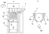
- the height changing portion 92 has two height changing portions 92A and 92B spaced apart in the X-axis direction.
- the height changing portion 92A contacts the corner portion 32A of the chemical bath 32 on the left side in the figure
- the height changing portion 92B contacts the corner portion 32B of the chemical solution tank 32 on the right side in the figure.
- the height changing portion 92A is provided on the inner wall surface 47A on one side of the sink tank 47
- the height changing portion 92B is provided on the inner wall surface 47A on the other side of the sink tank 47.
- Height change parts 92A and 92B can change height independently.
- the contact portion 93 is a member provided in the chemical bath 32 and contacts the support portion 94 .
- the contact portion 93 of the present embodiment has a convex spherical surface and is also called a “ball portion”.
- the support portion 94 is a member that contacts the contact portion 93 and supports the contact portion 93 .
- the support portion 94 of this embodiment has a concave spherical surface that receives the contact portion 93, which is a ball portion, and is also referred to as a "ball receiving portion".
- the posture of the chemical bath 32 can be freely adjusted.
- the attitude of the chemical tank 32 can be adjusted in any direction, and the parallelism of the chemical tank 32 can be adjusted. can be maintained with high accuracy.
- the chemical can be easily overflowed evenly from the four sides of the chemical bath 32, and the processing efficiency of the substrate 4 can be improved.
- the leveling work can be performed easily and in a short time because it is only necessary to change the height of the two corners. It is possible to achieve high maintainability.
- the height changing portion 95 has a structure similar to that of the height changing portion 92, and the contact portion 96 has a structure (ball portion) similar to that of the contact portion 93.
- the portion 97 has a structure (ball receiving portion) similar to that of the support portion 94 .
- the contact portion 96 provided in the cleaning tank 34 is received and supported by the support portion 97, and the height of the cleaning tank 34 is changed by the two height changing portions 95A and 95B.
- the posture of the tank 34 can be freely adjusted. As a result, the cleaning liquid can be easily overflowed evenly from the four sides of the cleaning tank 34, and the processing efficiency of the substrates 4 can be improved.
- the height changing portion 92 is provided on the rear side N2, and the contact portion 93 and the support portion 94 are provided on the front side N1.
- the height changing portion 95 is provided on the front side N1, and the contact portion 96 and the support portion 97 are provided on the rear side N2.
- the operator when leveling the chemical liquid tank 32, the operator can access the height changing part 92 from the rear surface 78 of the sink tank 47, and when leveling the cleaning tank 34, the operator can access the sink tank 47
- the height changer 95 can be accessed from the front face 58 of the . Therefore, it is not necessary to access the central portion of the sink tank 47, and the height changing portions 92 and 95 can be easily accessed from the outside of the sink tank 47, thereby facilitating the leveling work.
- FIG. 25 is a schematic enlarged view of the height changer 92 (95) viewed from the side.
- the height changer 92 (95) includes a cradle 100, an adjustment bolt 102, and a guide portion 104.
- the cradle 100 is a plate-like portion for receiving the corners 32A and 32B of the chemical bath 32.
- the cradle 100 is supported by adjusting bolts 102 from below.
- the adjustment bolt 102 is a member for moving the cradle 100 up and down, and is arranged with the head 103 directed downward.
- the adjusting bolt 102 and the cradle 100 supported by the adjusting bolt 102 move up and down integrally (arrow Z1). Thereby, the heights of the corners 32A and 32B of the chemical bath 32 can be changed.
- the adjusting bolt 102 is screwed into the guide portion 104 .
- the guide portion 104 supports the screwed bolt 102 and guides the vertical movement of the cradle 100 .
- the guide portion 104 has a substantially L-shaped cross section and is inserted through a through hole 106 formed in the receiving table 100 .
- the pedestal 100 supported by the adjustment bolt 102 moves up and down while maintaining an engaging relationship with the portion of the guide portion 104 which rises in the vertical direction, thereby moving up and down while maintaining a substantially horizontal state.
- the guide part 104 is fixed to the inner wall surfaces 47A and 47B (FIG. 24A) of the sink tank 47.
- the pedestal 100 and the adjusting bolt 102 are separated from the inner wall surfaces 47A and 47B, and the pedestal 100 on which the chemical tank 32 is mounted is positioned relative to the guide portion 104 and the sink tank 47. Can move up and down.
- FIG. 26 is a schematic enlarged view of a longitudinal section of the contact portion 93 (96) and the support portion 94 (97).
- the chemical bath 32 is provided with an attachment portion 107 for attaching the contact portion 93 .
- the contact portion 93 is attached to the lower surface of the attachment portion 107 .
- the contact portion 93 is a ball portion having a convex spherical surface 108
- the support portion 94 that receives the contact portion 93 is a ball receiving portion having a concave spherical surface 110
- the spherical surfaces 108 and 110 have different radii of curvature.
- the radius of curvature D1 of the spherical surface 108 is set shorter than the radius of curvature D2 of the spherical surface 110 . According to such setting of the radius of curvature, when the convex spherical surface 108 contacts the concave spherical surface 110, the contact point 112 is approximately one point, which is a so-called point contact.
- the point contact between the contact portion 93 and the support portion 94 allows the spherical surface 108 to move smoothly along the spherical surface 110, thereby facilitating the posture adjustment of the chemical tank 32.
- FIG. 27 and 28 are schematic plan views of the sink tank 47 including the chemical tank 32, the cleaning tank 34, and the leveling mechanisms 90 and 91.
- FIG. 27 shows a state in which the chemical liquid tank 32 and the cleaning tank 34 are arranged in the sink tank 47
- FIG. 28 shows a state in which the chemical liquid tank 32 and the cleaning tank 34 are removed from the sink tank 47.
- the chemical bath 32 further has two rod-shaped portions 114.
- the rod-shaped portion 114 is a member fixed to the side surface of the chemical bath 32 and extending in the Y-axis direction in a rod shape.
- One end of each of the rod-shaped portions 114 is received by the cradles 100 of the height changing portions 92A, 92B.
- the posture of the chemical tank 32 can be adjusted by changing the height of the cradle 100 by receiving one end of the rod-shaped portion 114 on the cradle 100 .
- the cleaning tank 34 has two bar-shaped parts 116 .
- the bar-shaped portions 116 are respectively received by the cradles 100 of the height changing portions 95A and 95B, and by changing the height of the cradles 100, the posture of the cleaning tank 34 can be adjusted.
- the mounting portion 107 to which the contact portions 93 and 96 are integrally mounted is provided on the front side N1 of the chemical tank 32, whereas it is provided on the rear side N2 of the cleaning tank . Accordingly, the mounting portion 107 of the chemical tank 32 and the mounting portion 107 of the cleaning tank 34 are arranged adjacent to the central portion of the sink tank 47 .
- the two mounting parts 107 collectively in the central part of the sink tank 47, the height is changed at the end part of the sink tank 47, and there is no need to access the central part of the sink tank 47.
- the space in 47 can be used effectively, and the posture can be easily adjusted.
- the support portions 94 and 97 are provided on the bottom surface 51C of the sink bath 47, and the guide portion 104 is provided inside the sink bath 47. It is provided on the wall surfaces 47A and 47B.
- the cradle 100 and the adjusting bolt 102 are also engaged with the guide portion 104, and the height changing portions 92A, 92B, 95A, and 95B are all provided in the sink tub 47.
- support portions 94 and 97 as ball receiving portions and height changing portions 92 and 95 are provided in the sink tank 47, and contact portions 93 and 96 as ball portions are provided in the chemical liquid tank 32 and the cleaning tank 34. (treatment tank).
- the leveling mechanisms 90 and 91 can be easily installed at the contact points between the chemical bath 32 and the cleaning bath 34 and the sink bath 47 .
- the leveling mechanism 90 for leveling the chemical bath 32 has two height changing portions 92, the contact portion 93, and the support portion 94, and the leveling mechanism 90 for leveling the cleaning bath 34 is provided.
- Mechanism 91 likewise has two height changing portions 95 , contact portion 96 and support portion 97 .
- the chemical module 7 (substrate processing module) of the embodiment includes the housing 20, and the cleaning tanks arranged in the Y-axis direction (first direction) in the housing 20, in which the substrates 4 can be respectively arranged.
- 34 and a chemical bath 32 processing bath
- leveling mechanisms 91 and 90 for leveling the cleaning bath 34 and the chemical bath 32.
- the leveling mechanisms 91 and 90 are provided in the cleaning bath 34 and the chemical bath 32.
- support portions 97 and 94 that contact the contact portions 96 and 93 and receive the contact portions 96 and 93; Height changing portions 95A, 95B, 92A and 92B are respectively provided.
- the contact portions 96 and 93 may be at least partially spherical, and may be entirely spherical, for example. Also, the spherical size is not particularly limited.
- the processing baths include the cleaning bath 34 (first bath) and the chemical solution bath 32 (second bath), and the leveling mechanisms 91 and 90 level the cleaning bath 34. and a leveling mechanism 90 (second leveling mechanism) for leveling the chemical tank 32 .
- the leveling mechanism 91 has a contact portion 96, a support portion 97, and two height changing portions 95A and 95B for changing the height of the cleaning tank 34.
- the leveling mechanism 90 has a contact portion 93 , a support portion 94 , and two height changing portions 92 A and 92 B for changing the height of the chemical bath 32 . According to such a configuration, each of the cleaning tank 34 and the chemical liquid tank 32 can be accurately leveled.
- the cleaning tank 34 is arranged on the front side N1 of the housing 20 with respect to the chemical liquid tank 32, and the height changing part 95 of the leveling mechanism 91 is located on the front side of the cleaning tank 34.
- the height changing part 92 of the leveling mechanism 90 is provided on the rear surface side N2 of the chemical tank 32 .
- another chemical module 7 can be connected in the X-axis direction (second direction) intersecting the Y-axis direction (first direction), and the substrate 4 is moved in the Y-axis direction. It further includes a first transporter 11 and a second transporter 48 that moves the substrate 4 in the X-axis direction. According to such a configuration, while the chemical modules 7 can be connected in the X-axis direction, the leveling mechanisms 90 and 91 in each chemical module 7 can be used to easily level the processing tanks.
- the cleaning tank 34 and the chemical liquid tank 32 are accommodated, and the module is separated from the housing 20 and can be pulled out along the Y-axis direction (first direction) with respect to the housing 20.
- a sink tank 47 is further provided. According to such a configuration, the sink tank 47 can be pulled out, thereby further improving maintainability.
- leveling mechanisms 91 and 90 are provided at contact points between the sink tank 47 and the cleaning tank 34 and the chemical liquid tank 32 (processing tank). With such a configuration, the leveling mechanisms 91 and 90 can be easily installed.
- the support portions 97 and 94 and the height changing portions 95 and 92 are provided in the sink tank 47, and the contact portions 96 and 93 are provided in the cleaning tank 34 and the chemical liquid tank 32 (processing tank). ). With such a configuration, the leveling mechanisms 91 and 90 can be easily installed.
- the contact portions 96 and 93 are partially spherical ball portions, and the support portions 97 and 94 are ball receiving portions for receiving the contact portions 96 and 93 .
- the leveling mechanisms 91 and 90 can be easily installed.
- the substrate processing apparatus 1 of the embodiment is connected to the chemical module 7 (substrate processing module) in the X-axis direction (second direction) intersecting the chemical module 7 with the Y-axis direction (first direction). and another chemical module 7 that According to such a configuration, it is possible to realize the substrate processing apparatus 1 with high maintainability while allowing a plurality of chemical modules 7 to be connected.
- the substrate processing unit 45 of the embodiment has a cleaning bath 34 and a chemical bath 32 (processing bath) in which the substrates 4 can be arranged, and the cleaning bath 34 and the chemical bath 32 are arranged in the Y-axis direction (first direction). and leveling mechanisms 91 and 90 for leveling the cleaning bath 34 and the chemical bath 32.
- the leveling mechanisms 91 and 90 are provided in the cleaning bath 34 and the chemical bath 32. support portions 97 and 94 that contact the contact portions 96 and 93 and receive the contact portions 96 and 93; , and 95A, 95B, 92A, 92B. According to such a configuration, it is possible to achieve the same effect as the chemical module 7 of the embodiment (see paragraph 0196).
- the sink tank 47 is separated from the housing 20 of the chemical module 7 and can be pulled out from the housing 20 .
- Such a configuration contributes to realization of a substrate processing module with high maintainability.
- the shape of the support portions 94 and 97 is not limited thereto. Any shape may be used as long as it can receive the
- a ball receiving portion having a concave polyhedral shape 210 instead of the concave spherical surface may be used.
- the polyhedral shape 210 has a vertical cross section shown in FIG. 29 composed of a plurality of straight lines.
- the support portions 94 and 97 provided in the sink tank 47 are concave ball receiving portions, and the contact portions 93 and 96 provided in the processing tank are convex ball portions.
- the relationship between the ball receiving portion and the ball portion may be reversed.
- the support portions 304 and 307 provided in the sink tank 47 are convex ball portions
- the contact portions 303 and 306 provided in the processing tank are concave ball portions. good too.
- the contact portion 303 provided in the chemical bath 32 receives the support portion 304
- the contact portion 306 provided in the cleaning bath 34 receives the support portion 307 .
- it is sufficient that one of the contact portion and the support portion is an at least partially spherical ball portion and the other is a ball receiving portion that receives the ball portion.
- FIG. 30 exemplifies a form in which the mounting portion 107 described above is omitted and the contact portions 303 and 306 also serve as the mounting portion 107 .
- the attachment portion 107 may be provided and the contact portions 303 and 306 may be attached to the attachment portion 107 as in the embodiment.
- FIG. 31 shows another modified example in which the mounting portion 107 is omitted.
- the contact portion 393 is directly attached to the bottom surface of the chemical bath 32 and the contact portion 396 is directly attached to the bottom surface of the cleaning bath 34 .
- the chemical bath 432 and the cleaning bath 434 may be integrally configured, and the two processing baths may be leveled simultaneously by one leveling mechanism 490.
- the chemical bath 432 and the cleaning bath 434 are integrated, and the leveling mechanism 490 includes a height changing portion 492 , a contact portion 493 and a support portion 494 .
- the height changing portion 492 is provided on the rear side N2 of the chemical bath 432 so as to support one corner of the chemical bath 432, and the contact portion 493 and the support portion 494 are provided on the front side N1 of the cleaning bath 434. be provided. As shown in FIG. 32B, two height changers 492 are provided to support two corners of the chemical bath 432 (height changers 492A and 492B).
- the height changing portion 492 is provided in the chemical bath 432 and the contact portion 493 and the support portion 494 are provided in the cleaning bath 434. may be provided, and the cleaning tank 434 may be provided with two height changing portions.
- height changing portions 92A and 92B are provided at one end (opposite side to the contact portion 93) of the chemical liquid tank 32 in the Y-axis direction to change the height.
- the portions 95A and 95B are provided at one end of the cleaning tank 34 in the Y-axis direction (the side opposite to the contact portion 96)
- the present invention is not limited to such a case.
- a height changer 500 is provided between both ends of the chemical tank 32 in the Y-axis direction, and a height changer 500 is provided between both ends of the cleaning tank 34 in the Y-axis direction.
- a unit 501 may be provided. In the example shown in FIG.
- height changing portions 500 are provided at one end and the other end of the chemical bath 32 in the X-axis direction, respectively, and height changing portions 501 are provided at one end and the other end of the cleaning bath 34 in the X-axis direction, respectively.
- the height changing portion 500 may be arranged on the side opposite to the contact portion 93 (upper side of the drawing) with respect to the center line X1, which is the center position of the chemical bath 32 in the Y-axis direction. It may be arranged on the side opposite to the contact portion 96 (lower side of the drawing) with respect to the center line X2, which is the central position of the tank 34 in the Y-axis direction.
- the position of the chemical bath 32 can be adjusted by changing the height of the chemical bath 32 at two locations using the height changing unit 500, and the height changing unit 501 can be
- the posture of the cleaning tank 34 can be adjusted by changing the height of the cleaning tank 34 at two points using the .
- Rotation arm part 44 Chuck part 46... Link part 48... 2nd conveyance part 45... Substrate processing unit 47... Sink tank 90... Leveling mechanism ( second leveling mechanism) 91... Leveling mechanism (first leveling mechanism) 92, 95... Height change part 93, 96... Contact part (ball part) 94, 97... Support portion (ball receiving portion)
Abstract
A substrate processing module (7) comprises a housing (20), two processing tanks (34, 32) which are arranged in a first direction inside the housing (20), and in each of which a substrate (4) can be disposed, and leveling mechanisms (91, 90) which are for leveling the processing tanks (34, 32). The leveling mechanisms (91, 90) have a contact parts (96, 93) which are provided to the processing tanks (34, 32), support parts (97, 94) which contact the contact part (96, 93) and support the contact parts (96, 93), and at least two height adjustment parts (95, 92) which are for changing the height of the processing tanks (34, 32).
Description
この発明は、基板を処理する基板処理モジュール、基板処理装置、および基板処理ユニットに関する。
The present invention relates to a substrate processing module, a substrate processing apparatus, and a substrate processing unit for processing substrates.
基板処理装置として、半導体ウェハなどの各種の基板(以下、「基板」という。)を所定の薬液で処理したあと、純水等の洗浄液で洗浄し、基板の表面に付着した異物を除去する洗浄装置がある。洗浄装置には、薬液および洗浄液の中に基板を浸漬させることによって洗浄処理を行うウェット型の洗浄装置がある。
As a substrate processing apparatus, after processing various substrates such as semiconductor wafers (hereinafter referred to as "substrates") with a predetermined chemical solution, they are cleaned with a cleaning liquid such as pure water to remove foreign matter adhering to the surface of the substrates. I have a device. Among cleaning apparatuses, there is a wet-type cleaning apparatus that performs cleaning processing by immersing a substrate in a chemical solution and a cleaning liquid.
特許文献1は、薬液槽および洗浄槽が装置の長手方向に複数対で配置されているとともに、主搬送機構および副搬送機構を有する基板処理装置を開示する。主搬送機構は、複数の基板を装置の一端側から他端側まで長手方向に移動させる。副搬送機構は、複数の基板を一対の薬液槽および洗浄槽の範囲内で長手方向および上下方向に移動させる。
Patent Document 1 discloses a substrate processing apparatus in which a plurality of pairs of chemical liquid tanks and cleaning tanks are arranged in the longitudinal direction of the apparatus, and which has a main transport mechanism and a sub-transport mechanism. A main transport mechanism longitudinally moves a plurality of substrates from one end of the apparatus to the other end thereof. The sub-transport mechanism moves the plurality of substrates in the longitudinal direction and the vertical direction within the range of the pair of chemical bath and cleaning bath.
特許文献1では、複数対の薬液槽および洗浄槽が装置の長手方向に隣り合っているので、或る薬液槽に貯留される或る薬液の雰囲気によって、隣りに位置する別の薬液槽および洗浄槽が汚染されること(すなわち薬液によるコンタミネーション)が生じる。また、主搬送機構および副搬送機構が薬液槽および洗浄槽に面しているので、パーティクルによるコンタミネーションが生じる。また、薬液槽および洗浄槽が長手方向に複数対で配置されているので、装置が長手方向に長くなる。また、複数対の薬液槽および洗浄槽が装置内で固定して設置されているので、処理プロセスの変更ニーズに対してフレキシブルに対応できず、メンテナンスする際も困難になる場合がある。
In Patent Document 1, since a plurality of pairs of chemical liquid tanks and cleaning tanks are adjacent to each other in the longitudinal direction of the apparatus, the atmosphere of a certain chemical liquid stored in a certain chemical liquid tank causes the adjacent chemical liquid tanks and cleaning tanks to be separated from each other. Contamination of the bath (ie, chemical contamination) occurs. In addition, since the main transport mechanism and sub-transport mechanism face the chemical tank and the cleaning tank, contamination by particles occurs. In addition, since a plurality of pairs of chemical liquid tanks and cleaning tanks are arranged in the longitudinal direction, the apparatus becomes long in the longitudinal direction. In addition, since a plurality of pairs of chemical tanks and cleaning tanks are fixedly installed in the apparatus, it is not possible to flexibly respond to changes in treatment process needs, and maintenance may be difficult.
よって、薬液やパーティクルなどによるコンタミネーションの抑制、装置の小型化、フレキシブルな対応で拡張性の高い構成、メンテナンス性の向上を可能にすることが望まれる。
Therefore, it is desirable to suppress contamination due to chemicals and particles, reduce the size of the device, provide a highly expandable configuration with flexible response, and improve maintainability.
そこで、この発明の課題は、メンテナンス性を向上させることができる基板処理モジュール、基板処理装置、および基板処理ユニットを提供することにある。
Therefore, an object of the present invention is to provide a substrate processing module, a substrate processing apparatus, and a substrate processing unit that can improve maintainability.
上記課題を解決するため、この発明の一態様に係る基板処理モジュールは、筐体と、前記筐体内において第1方向に配列され、基板をそれぞれ配置可能な2つの処理槽と、前記処理槽のレベリングを行うためのレベリング機構と、を備え、前記レベリング機構は、前記処理槽に設けられた接触部と、前記接触部に接触して前記接触部を支持する支持部と、前記処理槽の高さを変更するための少なくとも2つの高さ変更部と、を有する。
In order to solve the above-described problems, a substrate processing module according to an aspect of the present invention includes a housing, two processing tanks arranged in a first direction in the housing and in which substrates can be respectively placed, and a leveling mechanism for performing leveling, the leveling mechanism comprising: a contact portion provided in the processing bath; a support portion that contacts the contact portion and supports the contact portion; and at least two height changers for changing the height.
また、この発明の一態様に係る基板処理装置は、前記基板処理モジュールと、前記別のモジュールとを備える。
A substrate processing apparatus according to one aspect of the present invention includes the substrate processing module and the another module.
また、この発明の一態様に係る基板処理ユニットは、基板をそれぞれ配置可能な2つの処理槽と、前記処理槽を第1方向に配列した状態で収容するシンク槽と、前記処理槽のレベリングを行うためのレベリング機構と、を備え、前記レベリング機構は、前記処理槽に設けられた接触部と、前記接触部に接触して前記接触部を支持する支持部と、前記処理槽の高さを変更するための少なくとも2つの高さ変更部と、を有する。
Further, a substrate processing unit according to an aspect of the present invention includes two processing baths in which substrates can be placed respectively, a sink bath accommodating the processing baths arranged in a first direction, and leveling of the processing baths. and a leveling mechanism for performing the above-described processing, wherein the leveling mechanism includes a contact portion provided in the processing bath, a support portion that contacts the contact portion and supports the contact portion, and a height of the processing bath. and at least two height changes for changing.
この発明によれば、メンテナンス性を向上させることができる。
According to this invention, maintainability can be improved.
以下、図面を参照しながら、この発明に係る基板処理装置1の実施の形態を説明する。
An embodiment of a substrate processing apparatus 1 according to the present invention will be described below with reference to the drawings.
なお、本明細書において、「モジュール」とは、規格化されて着脱可能(交換可能)に構成された構成要素であって、使用されるときにまとまった一つの構成単位として取り扱われる構成要素を意味する。また、「第1方向」とは、一対の薬液槽および洗浄槽が配列される方向、すなわち、基板処理装置1の短手方向(例えば、前後方向や縦方向)を意味する。また、「第2方向」とは、第1方向および上下方向に交差する方向であって複数のモジュールが連設される方向、すなわち、基板処理装置1の長手方向(例えば、左右方向や横方向)を意味する。第1方向は、TD(Transverse Direction)方向、第2方向は、MD(Machine Direction)方向と称してもよい。図においては、「第1方向」がY軸方向として、「第2方向」がX軸方向として、「上下方向」がZ軸方向として示されている。第1方向と第2方向と上下方向とは、互いに交差する(例えば直交する)。
In this specification, the term "module" refers to a component that is standardized and detachable (exchangeable), and is handled as a unit when used. means. Also, the "first direction" means the direction in which the pair of chemical baths and cleaning baths are arranged, that is, the lateral direction of the substrate processing apparatus 1 (for example, the front-rear direction or the vertical direction). In addition, the "second direction" is a direction that intersects the first direction and the vertical direction and is a direction in which a plurality of modules are arranged in a row, that is, the longitudinal direction of the substrate processing apparatus 1 (for example, the horizontal direction or the horizontal direction). ). The first direction may be called a TD (Transverse Direction) direction, and the second direction may be called an MD (Machine Direction) direction. In the drawing, the "first direction" is the Y-axis direction, the "second direction" is the X-axis direction, and the "vertical direction" is the Z-axis direction. The first direction, the second direction, and the vertical direction intersect each other (for example, are orthogonal).
〔実施形態〕
図1から図10を参照しながら、一実施形態に係る基板処理装置1を説明する。図1は、一実施形態に係る基板処理装置1を説明する斜視図である。図2は、図1に示した基板処理装置1の構成要素を説明する斜視図である。図3は、図1に示した基板処理装置1におけるケミカルモジュール7を説明する斜視図である。図4は、図1に示した基板処理装置1における第2搬送機構9を説明する斜視図である。図5は、図3に示したケミカルモジュール7の要部を説明する斜視図である。図6は、図1に示した基板処理装置1における搬出モジュール8を説明する斜視図である。図7は、図1に示した基板処理装置1における搬入モジュール5を説明する斜視図である。図8は、図3に示したケミカルモジュール7における上下搬送部13の動きを説明する図である。図9は、図3に示したケミカルモジュール7における第1搬送部11の動きを説明する図である。図10は、基板4を保持するキャリア2を説明する図である。図11は、図1に示した基板処理装置1における乾燥モジュール6を説明する斜視図である。 [Embodiment]
Asubstrate processing apparatus 1 according to an embodiment will be described with reference to FIGS. 1 to 10. FIG. FIG. 1 is a perspective view illustrating a substrate processing apparatus 1 according to one embodiment. FIG. 2 is a perspective view illustrating constituent elements of the substrate processing apparatus 1 shown in FIG. FIG. 3 is a perspective view for explaining the chemical module 7 in the substrate processing apparatus 1 shown in FIG. 1. As shown in FIG. FIG. 4 is a perspective view illustrating the second transfer mechanism 9 in the substrate processing apparatus 1 shown in FIG. 1. FIG. FIG. 5 is a perspective view for explaining the essential parts of the chemical module 7 shown in FIG. FIG. 6 is a perspective view for explaining the unloading module 8 in the substrate processing apparatus 1 shown in FIG. FIG. 7 is a perspective view for explaining the loading module 5 in the substrate processing apparatus 1 shown in FIG. 8A and 8B are diagrams for explaining the movement of the vertical transfer section 13 in the chemical module 7 shown in FIG. 9A and 9B are diagrams for explaining the movement of the first conveying section 11 in the chemical module 7 shown in FIG. 10A and 10B are diagrams illustrating the carrier 2 holding the substrate 4. FIG. 11 is a perspective view illustrating the drying module 6 in the substrate processing apparatus 1 shown in FIG. 1. FIG.
図1から図10を参照しながら、一実施形態に係る基板処理装置1を説明する。図1は、一実施形態に係る基板処理装置1を説明する斜視図である。図2は、図1に示した基板処理装置1の構成要素を説明する斜視図である。図3は、図1に示した基板処理装置1におけるケミカルモジュール7を説明する斜視図である。図4は、図1に示した基板処理装置1における第2搬送機構9を説明する斜視図である。図5は、図3に示したケミカルモジュール7の要部を説明する斜視図である。図6は、図1に示した基板処理装置1における搬出モジュール8を説明する斜視図である。図7は、図1に示した基板処理装置1における搬入モジュール5を説明する斜視図である。図8は、図3に示したケミカルモジュール7における上下搬送部13の動きを説明する図である。図9は、図3に示したケミカルモジュール7における第1搬送部11の動きを説明する図である。図10は、基板4を保持するキャリア2を説明する図である。図11は、図1に示した基板処理装置1における乾燥モジュール6を説明する斜視図である。 [Embodiment]
A
基板処理装置1は、キャリア2に保持された複数枚の基板4に対して各種の処理を施すためのモジュールを少なくとも1つ備える。基板4は、具体的には例えば、半導体基板、液晶表示装置用ガラス基板、フォトマスク用ガラス基板、光ディスク用基板、MEMSセンサー基板、太陽電池用パネルなどである。モジュールは、規格化された筐体20を有し、第2方向(X軸方向、基板処理装置1の長手方向であり、以下、「第2方向」という)に着脱可能(交換可能)に構成されている。モジュールの上部には、ファンフィルタユニット24が配設されている。ファンフィルタユニット24は、クリーンルーム内の空気を取り込んでモジュール内に送り出すためのファンおよびフィルタを備える。ファンフィルタユニット24は、モジュール内の処理空間に清浄空気のダウンフローを形成する。ファンフィルタユニット24を配設する代わりに、クリーンルーム内の清浄な空気を取り込む別の構成にすることもできる。
The substrate processing apparatus 1 includes at least one module for performing various types of processing on multiple substrates 4 held by the carrier 2 . Specifically, the substrate 4 is, for example, a semiconductor substrate, a glass substrate for a liquid crystal display device, a glass substrate for a photomask, an optical disc substrate, a MEMS sensor substrate, a solar cell panel, or the like. The module has a standardized housing 20 and is detachable (exchangeable) in a second direction (the X-axis direction, which is the longitudinal direction of the substrate processing apparatus 1, hereinafter referred to as the "second direction"). It is A fan filter unit 24 is arranged on top of the module. The fan filter unit 24 has a fan and a filter for taking air in the clean room and sending it out into the module. A fan filter unit 24 creates a downflow of clean air into the process space within the module. Instead of arranging the fan filter unit 24, another configuration for taking in clean air in the clean room can be used.
図1および図2に示すように、基板処理装置1は、例えば、搬入モジュール5と、乾燥モジュール6と、ケミカルモジュール7(基板処理モジュール)と、搬出モジュール8と、第2搬送機構9とを備える。搬入モジュール5と、ケミカルモジュール7と、乾燥モジュール6と、搬出モジュール8とは、第2方向に沿って隣接して配設されている。搬入モジュール5と、ケミカルモジュール7と、乾燥モジュール6と、搬出モジュール8とは、第2方向に着脱可能に連結されるように構成される。これにより、処理プロセスの変更ニーズに対してフレキシブルに対応でき、拡張性が高くなる。
As shown in FIGS. 1 and 2, the substrate processing apparatus 1 includes, for example, a loading module 5, a drying module 6, a chemical module 7 (substrate processing module), a loading module 8, and a second transport mechanism 9. Prepare. The carry-in module 5, the chemical module 7, the drying module 6, and the carry-out module 8 are arranged adjacent to each other along the second direction. The loading module 5, the chemical module 7, the drying module 6, and the loading module 8 are configured to be detachably connected in the second direction. As a result, it is possible to respond flexibly to changes in the processing process, and the scalability is enhanced.
第2搬送機構9は、第2方向に延在して、図10に示す複数枚の基板4を保持するキャリア2を第2方向に搬送する。第2搬送機構9は、搬入モジュール5と、ケミカルモジュール7と、乾燥モジュール6と、搬出モジュール8とにおける第1方向(Y軸方向、基板処理装置1の短手方向であり、以下、「第1方向」という)の後方側の上部に配設されている。
The second transport mechanism 9 extends in the second direction and transports the carrier 2 holding the plurality of substrates 4 shown in FIG. 10 in the second direction. The second transport mechanism 9 is arranged in the first direction (Y-axis direction, the lateral direction of the substrate processing apparatus 1) in the loading module 5, the chemical module 7, the drying module 6, and the unloading module 8. 1 direction”).
基板処理装置1は、図示しない制御部を有する。制御部は、例えば、基板処理装置1の各要素の動作制御およびデータ演算を行う。制御部は、例えば、CPU(Central Processing Unit)と、RAM(Random Access Memory)と、ROM(Read Only Memory)とを有する。CPUは、ROMに格納されたプログラムに従った制御(例えば、第1搬送部11、上下搬送部13および第2搬送部48によるキャリア2の搬送動作などの制御)を実行する。
The substrate processing apparatus 1 has a control section (not shown). The control unit, for example, performs operation control and data calculation of each element of the substrate processing apparatus 1 . The control unit has, for example, a CPU (Central Processing Unit), a RAM (Random Access Memory), and a ROM (Read Only Memory). The CPU executes control according to a program stored in the ROM (for example, control of the transport operation of the carrier 2 by the first transport section 11, the vertical transport section 13, and the second transport section 48).
搬入モジュール5では、処理前の基板4が、キャリア2を1つの単位として装置内に搬入される。乾燥モジュール6では、例えば、IPA(イソプロピルアルコール)などによる基板4の蒸気乾燥が、キャリア2を1つの単位として実行される。ケミカルモジュール7では、基板4の洗浄処理が、キャリア2を1つの単位として実行される。搬出モジュール8では、洗浄処理後の基板4が、キャリア2を1つの単位として装置外に搬出される。
In the loading module 5, the unprocessed substrates 4 are loaded into the apparatus with the carrier 2 as one unit. In the drying module 6, for example, vapor drying of the substrate 4 with IPA (isopropyl alcohol) or the like is performed with the carrier 2 as one unit. In the chemical module 7, the cleaning process of the substrate 4 is performed with the carrier 2 as one unit. In the carry-out module 8, the substrates 4 after the cleaning process are carried out of the apparatus with the carrier 2 as one unit.
搬入モジュール5は、ローダ部とも呼ばれ、基板処理装置1の第2方向の上流側に配設される。図7に示すように、搬入モジュール5は、その筐体20の第2方向の上流側の側面において、開閉可能に構成された搬入部26を有する。キャリア2は、搬入部26を介して搬入モジュール5の内部に搬入される。搬入モジュール5の内部に搬入されたキャリア2は、載置台22に載置される。搬入モジュール5の内部において、キャリア2の第1方向への搬送は、アーム16を介して、第1搬送部11によって行われ、キャリア2の上下方向への搬送は、アーム16を介して、上下搬送部13によって行われる。第1搬送部11の第1アクチュエータ12は、載置台22の載置面よりも側方下部に配置される。上下搬送部13の上下アクチュエータ14も、載置台22の載置面よりも側方下部に配置される。すなわち、ファンフィルタユニット24からのダウンフローとアーム16のアーム長さとにより、載置台22に載置されるキャリア2は、第1アクチュエータ12および上下アクチュエータ14から影響を受けないように隔離されている。これにより、第1アクチュエータ12および上下アクチュエータ14から発生するパーティクルによる、搬入モジュール5内でのキャリア2のコンタミネーションを抑制できる。
The loading module 5 is also called a loader section, and is arranged on the upstream side of the substrate processing apparatus 1 in the second direction. As shown in FIG. 7, the loading module 5 has a loading section 26 configured to be openable and closable on the side surface of the casing 20 on the upstream side in the second direction. The carrier 2 is loaded into the loading module 5 via the loading section 26 . The carrier 2 loaded into the loading module 5 is mounted on the mounting table 22 . Inside the loading module 5 , the carrier 2 is conveyed in the first direction by the first conveying section 11 via the arm 16 , and the carrier 2 is vertically conveyed via the arm 16 . It is performed by the transport unit 13 . The first actuator 12 of the first transfer section 11 is arranged laterally below the mounting surface of the mounting table 22 . The vertical actuator 14 of the vertical transfer section 13 is also arranged laterally below the mounting surface of the mounting table 22 . That is, the carrier 2 mounted on the mounting table 22 is isolated from the first actuator 12 and the vertical actuator 14 by the downflow from the fan filter unit 24 and the arm length of the arm 16. . As a result, contamination of the carrier 2 inside the loading module 5 by particles generated from the first actuator 12 and the vertical actuator 14 can be suppressed.
搬出モジュール8は、アンローダ部とも呼ばれ、基板処理装置1の第2方向の下流側に配設される。図6に示すように、搬出モジュール8の内部に搬入されたキャリア2は、載置台22に載置される。搬出モジュール8の内部において、キャリア2の第1方向への搬送は、アーム16を介して、第1搬送部11によって行われ、キャリア2の上下方向への搬送は、アーム16を介して、上下搬送部13によって行われる。第1搬送部11の第1アクチュエータ12は、載置台22の載置面よりも側方下部に配置される。上下搬送部13の上下アクチュエータ14も、載置台22の載置面よりも側方下部に配置される。すなわち、ファンフィルタユニット24からのダウンフローとアーム16のアーム長さとにより、載置台22に載置されるキャリア2は、第1アクチュエータ12および上下アクチュエータ14から影響を受けないように隔離されている。これにより、第1アクチュエータ12および上下アクチュエータ14から発生するパーティクルによる、搬出モジュール8内でのキャリア2のコンタミネーションを抑制できる。搬出モジュール8は、その筐体20の第2方向の下流側の側面において、開閉可能に構成された搬出部27を有する。キャリア2は、搬出部27を介して搬出モジュール8の外部、すなわち基板処理装置1の外部に搬出される。
The unloading module 8 is also called an unloader section, and is arranged downstream of the substrate processing apparatus 1 in the second direction. As shown in FIG. 6 , the carrier 2 loaded into the carry-out module 8 is placed on the mounting table 22 . Inside the carry-out module 8 , the carrier 2 is transported in the first direction by the first transport section 11 via the arm 16 , and the carrier 2 is vertically transported via the arm 16 . It is performed by the transport unit 13 . The first actuator 12 of the first transfer section 11 is arranged laterally below the mounting surface of the mounting table 22 . The vertical actuator 14 of the vertical transfer section 13 is also arranged laterally below the mounting surface of the mounting table 22 . That is, the carrier 2 mounted on the mounting table 22 is isolated from the first actuator 12 and the vertical actuator 14 by the downflow from the fan filter unit 24 and the arm length of the arm 16. . As a result, contamination of the carrier 2 inside the carry-out module 8 due to particles generated from the first actuator 12 and the vertical actuator 14 can be suppressed. The carry-out module 8 has a carry-out section 27 configured to be openable and closable on the side surface of the housing 20 on the downstream side in the second direction. The carrier 2 is carried out to the outside of the carry-out module 8 , that is, the outside of the substrate processing apparatus 1 through the carry-out part 27 .
なお、上記態様では、キャリア2が、搬入モジュール5から搬出モジュール8に向けて第2方向に沿って一方向に搬送されるが、別の態様にすることもできる。例えば、基板処理装置1が搬入モジュール5または搬出モジュール8のいずれか一方だけを備えて、搬入モジュール5がローダおよびアンローダの両方の機能を有するか、または、搬出モジュール8がローダおよびアンローダの両方の機能を有することができる。このとき、キャリア2が、第2方向に沿って一方向および他方向の両方向に搬送される(すなわち、第2方向に沿って往復搬送される)。
In the above aspect, the carrier 2 is transported in one direction along the second direction from the loading module 5 toward the unloading module 8, but another aspect is also possible. For example, the substrate processing apparatus 1 may include only one of the loading module 5 and the unloading module 8, and the loading module 5 has both loader and unloader functions, or the unloading module 8 may function as both a loader and an unloader. can have a function. At this time, the carrier 2 is transported in both one direction and the other direction along the second direction (that is, transported back and forth along the second direction).
基板処理装置1は、少なくとも1つの乾燥モジュール6を有する。乾燥モジュール6は、図1に示すように、例えば、ケミカルモジュール7と搬出モジュール8との間に設置される。
The substrate processing apparatus 1 has at least one drying module 6. The drying module 6 is installed, for example, between the chemical module 7 and the unloading module 8, as shown in FIG.
図11に示すように、乾燥モジュール6は、例えば、他のモジュール5,7,8と同様に、キャリア2を第1方向に搬送する第1搬送部11と、キャリア2を上下方向に搬送する上下搬送部13とを有する。第1搬送部11は、第1アクチュエータ12を有し、上下搬送部13は、上下アクチュエータ14を有する。
As shown in FIG. 11 , the drying module 6 includes, for example, a first transport section 11 that transports the carrier 2 in the first direction and a and a vertical transport section 13 . The first transport section 11 has a first actuator 12 , and the vertical transport section 13 has a vertical actuator 14 .
乾燥モジュール6は、乾燥チャンバー31を有する。乾燥チャンバー31は、例えば、乾燥モジュール6における第1方向の前方側に配設される。ケミカルモジュール7によって各種の薬液洗浄やエッチングやレジスト剥離などの各種の薬液処理が行われた後の基板4を乾燥させる乾燥処理が、乾燥チャンバー31において行われる。乾燥モジュール6において、基板4を保持するキャリア2は、アーム16を介して、上下搬送部13によって乾燥チャンバー31に対して上下方向に搬送される。第1アクチュエータ12および上下アクチュエータ14が、乾燥チャンバー31の側方下部において、乾燥チャンバー31から離間して配置される。したがって、乾燥チャンバー31は、第1アクチュエータ12および上下アクチュエータ14から影響を受けないように隔離されている。
The drying module 6 has a drying chamber 31. The drying chamber 31 is arranged, for example, on the front side of the drying module 6 in the first direction. A drying process is performed in the drying chamber 31 to dry the substrate 4 after being subjected to various chemical liquid treatments such as cleaning, etching, and resist stripping by the chemical module 7 . In the drying module 6 , the carrier 2 holding the substrate 4 is vertically transported to the drying chamber 31 by the vertical transport section 13 via the arm 16 . A first actuator 12 and an up/down actuator 14 are arranged at a lateral lower portion of the drying chamber 31 and spaced apart from the drying chamber 31 . Therefore, the drying chamber 31 is isolated from the first actuator 12 and the vertical actuator 14 so as not to be affected.
この乾燥処理では、通常公知の乾燥方法を用いることができる。具体的には、例えば、IMD(IPA Mist Dryer)と呼ばれる、Marangoni効果を用いた乾燥方法を用いることができる。この乾燥方法は、基板4を保持するキャリア2を、乾燥チャンバー31に設けられた純水槽内に浸漬し、その水面にIPAのミスト若しくは蒸気化したIPAを連続的に供給し、基板4を上昇若しくは下降させるかまたは水面をオーバーフロー若しくはダウンフローさせる際に水面を通過する基板4の表面に生じる表面張力の差を用いる。
A commonly known drying method can be used in this drying treatment. Specifically, for example, a drying method using the Marangoni effect called IMD (IPA Mist Dryer) can be used. In this drying method, the carrier 2 holding the substrate 4 is immersed in a pure water tank provided in the drying chamber 31, and IPA mist or vaporized IPA is continuously supplied to the water surface to raise the substrate 4. Alternatively, the surface tension difference that occurs on the surface of the substrate 4 passing over the water surface when it is lowered or caused to overflow or downflow the water surface is used.
また、別の乾燥方法として、例えば、Spin Dryerと呼ばれる遠心力による乾燥を用いることもできる。この乾燥方法は、乾燥チャンバー31内に設けられた回転ロータに基板4を保持するキャリア2をセットし、リテーナと呼ばれる保定装置により、キャリア2および基板4を固定した後、回転ロータを回転させることによって生じる遠心力を用いる。
As another drying method, for example, drying by centrifugal force called Spin Dryer can also be used. In this drying method, the carrier 2 holding the substrate 4 is set on a rotating rotor provided in the drying chamber 31, and the rotating rotor is rotated after the carrier 2 and the substrate 4 are fixed by a retaining device called a retainer. using the centrifugal force caused by
また、別の乾燥方法として、例えば、Vapor Dryerと呼ばれる蒸気洗浄による乾燥を用いることができる。この乾燥方法は、蒸発潜熱の小さな溶媒(例えば、IPA)を加熱して作った飽和蒸気を乾燥チャンバー31内に充満させ、その蒸気温度よりも低温の基板4を保持するキャリア2を乾燥チャンバー31にセットし、基板4の表面に凝集液化するIPAにより、キャリア2および基板4の表面を洗浄し、キャリア2および基板4がIPA蒸気と同じ温度に暖まったときに、キャリア2および基板4の表面へのIPAの凝集液化を停止させ、キャリア2および基板4を乾燥する。
In addition, as another drying method, for example, drying by steam washing called Vapor Dryer can be used. In this drying method, the drying chamber 31 is filled with saturated vapor made by heating a solvent with a small latent heat of vaporization (for example, IPA), and the carrier 2 holding the substrate 4 at a temperature lower than the vapor temperature is placed in the drying chamber 31. and wash the surfaces of the carrier 2 and the substrate 4 with IPA that condenses and liquefies on the surface of the substrate 4, and when the carrier 2 and the substrate 4 warm to the same temperature as the IPA vapor, the surfaces of the carrier 2 and the substrate 4 Stop the IPA agglomeration liquefaction into the carrier 2 and the substrate 4 dry.
さらに別の乾燥方法として、N2によるN2ブロー乾燥なども用いることができる。いずれの乾燥方法においても、乾燥チャンバー31は、基板4を保持するキャリア2を搬送する上下アクチュエータ14や第1アクチュエータ12から影響を受けないように隔離されている。これにより、上下アクチュエータ14や第1アクチュエータ12から発生するパーティクルによる、乾燥モジュール6内でのコンタミネーションを抑制できる。なお、第1アクチュエータ12および上下アクチュエータ14を、乾燥チャンバー31の第1方向の後方側の下部において、乾燥チャンバー31から離間して配置することもできる。また、上下方向の搬送だけでよい場合には、乾燥モジュール6は、第1搬送部11を備えなくともよい。
Still another drying method such as N2 blow drying with N2 can be used. In any drying method, the drying chamber 31 is isolated so as not to be affected by the vertical actuator 14 and the first actuator 12 that transport the carrier 2 holding the substrate 4 . As a result, contamination inside the drying module 6 due to particles generated from the vertical actuator 14 and the first actuator 12 can be suppressed. It should be noted that the first actuator 12 and the vertical actuator 14 can also be arranged in the lower part of the rear side of the drying chamber 31 in the first direction, spaced apart from the drying chamber 31 . Further, if only vertical transport is required, the drying module 6 does not need to include the first transport section 11 .
ケミカルモジュール7は、少なくとも1つのモジュールを有する。ケミカルモジュール7は、図1および図2に示すように、例えば、第1ケミカルモジュール7a、第2ケミカルモジュール7b、第3ケミカルモジュール7cおよび第4ケミカルモジュール7dを有する。ケミカルモジュール7では、APM(ammonium hydroxide-hydrogen peroxide mixture)洗浄、SPM(sulfuric acid-hydrogen peroxide mixture)洗浄、HPM(hydrochloric acid-hydrogen peroxide mixture)、DHF(diluted hydrofluoric acid)洗浄などの各種の薬液洗浄やエッチングやレジスト剥離などの各種の薬液処理が行われる。これらの薬液処理は、基板4に対する薬液処理の種類によって任意に組み合わせることができる。各ケミカルモジュール7a,7b,7c,7dは、第2方向に着脱可能に連結されるように構成される。これにより、処理プロセスの変更ニーズに対してフレキシブルに対応でき、拡張性が高くなる。
The chemical module 7 has at least one module. The chemical module 7, as shown in FIGS. 1 and 2, has, for example, a first chemical module 7a, a second chemical module 7b, a third chemical module 7c and a fourth chemical module 7d. In the chemical module 7, various chemical cleaning such as APM (ammonium hydroxide-hydrogen peroxide mixture) cleaning, SPM (sulfuric acid-hydrogen peroxide mixture) cleaning, HPM (hydrochloric acid-hydrogen peroxide mixture), DHF (diluted hydrofluoric acid) cleaning Various chemical treatments such as etching and resist stripping are performed. These chemical treatments can be arbitrarily combined depending on the type of chemical treatment for the substrate 4 . Each chemical module 7a, 7b, 7c, 7d is configured to be detachably connected in the second direction. As a result, it is possible to respond flexibly to changes in the processing process, and the scalability is enhanced.
図3、図5および図9に示すように、ケミカルモジュール7は、薬液洗浄を行う薬液槽32(第2槽)と、純水洗浄(リンス)を行う洗浄槽34(第1槽)とを有する。薬液槽32は第1方向の後方側に配設されて、洗浄槽34は第1方向の前方側に配設される。すなわち、薬液槽32および洗浄槽34は、第1方向に配列される。これにより、ケミカルモジュール7の第2方向の幅が狭くなるので、基板処理装置1を小型化できる。なお、薬液槽32が第1方向の前方側に配設されるとともに洗浄槽34が第1方向の後方側に配設される構成にすることもできる。また、薬液槽32から発生する薬液蒸気を排気するための共通排気ダクト29を第1方向の後方側に配設できるので、基板処理装置1のメンテナンスが容易になる。薬液槽32には、上述した各種の薬液が貯留される。洗浄槽34には、純水が貯留される。薬液槽32は、例えば、キャリア2が薬液に浸漬される内槽と、内槽の上端からオーバーフローした薬液を回収する外槽とを有する。キャリア2の搬送動作に関係しないタイミングでは、薬液槽32の開口部は、蓋によって閉じられる。
As shown in FIGS. 3, 5 and 9, the chemical module 7 includes a chemical bath 32 (second bath) for chemical cleaning and a cleaning bath 34 (first bath) for pure water cleaning (rinsing). have. The chemical bath 32 is arranged on the rear side in the first direction, and the cleaning bath 34 is arranged on the front side in the first direction. That is, the chemical bath 32 and the cleaning bath 34 are arranged in the first direction. As a result, the width of the chemical module 7 in the second direction is narrowed, so that the substrate processing apparatus 1 can be miniaturized. It is also possible to adopt a configuration in which the chemical solution tank 32 is arranged on the front side in the first direction and the cleaning tank 34 is arranged on the rear side in the first direction. Further, since the common exhaust duct 29 for exhausting the chemical vapor generated from the chemical tank 32 can be arranged on the rear side in the first direction, maintenance of the substrate processing apparatus 1 is facilitated. Various chemical solutions described above are stored in the chemical solution tank 32 . Pure water is stored in the cleaning tank 34 . The chemical bath 32 has, for example, an inner bath in which the carrier 2 is immersed in the chemical and an outer bath in which the chemical overflowing from the upper end of the inner bath is recovered. The opening of the chemical tank 32 is closed with a lid at timings not related to the transport operation of the carrier 2 .
薬液槽32の第2方向における側方には、2つの側方壁37,37が設けられる。すなわち、薬液槽32の第2方向における側方が、側方壁37によって仕切られる。これにより、隣りに位置するケミカルモジュール7の薬液槽32に貯留される薬液の雰囲気によるコンタミネーションを抑制できる。それとともに、薬液槽32の第1方向における後方には、後方壁38が設けられる。薬液槽32は、2つの側方壁37,37と後方壁38とによって、上下方向から見てU字状に囲まれている。
Two side walls 37, 37 are provided on the sides of the chemical bath 32 in the second direction. That is, the side wall 37 partitions the side of the chemical bath 32 in the second direction. As a result, contamination due to the atmosphere of the chemical liquid stored in the chemical liquid tank 32 of the chemical module 7 located next to it can be suppressed. In addition, a rear wall 38 is provided behind the chemical bath 32 in the first direction. The chemical bath 32 is surrounded by two side walls 37, 37 and a rear wall 38 in a U shape when viewed from above and below.
例えば、側方排気口36aを有する2つの側方排気ダクト36,36を、薬液槽32の側方上部にそれぞれ配設することができる。2つの側方排気口36a,36aは、薬液槽32の開口部よりもわずかに低いもののほぼ同じ高さに位置する。後方壁38には、後方排気ダクト39(図9に図示)の後方排気口39aが配設される。2つの側方排気ダクト36,36と後方排気ダクト39とは、共通排気ダクト29から分岐していて共通排気ダクト29に接続される。後方排気口39aは、薬液槽32の開口部よりも上方に位置する。このように、薬液槽32から蒸発する薬液蒸気を排気する側方排気口36aおよび後方排気口39aが、前記薬液槽32の周囲に配設される。これにより、薬液槽32から発生する薬液蒸気が、ケミカルモジュール7内の処理空間に拡散することが抑制でき、ケミカルモジュール7内の処理空間で搬送される基板4のコンタミネーションを抑制できる。
For example, two side exhaust ducts 36, 36 having a side exhaust port 36a can be arranged in the lateral upper part of the chemical bath 32, respectively. The two side exhaust ports 36a, 36a are positioned slightly lower than the opening of the chemical bath 32, but at approximately the same height. The rear wall 38 is provided with a rear exhaust port 39a of a rear exhaust duct 39 (shown in FIG. 9). Two side exhaust ducts 36 , 36 and a rear exhaust duct 39 are branched from a common exhaust duct 29 and connected to the common exhaust duct 29 . The rear exhaust port 39 a is located above the opening of the chemical bath 32 . In this manner, the side exhaust port 36 a and the rear exhaust port 39 a for exhausting the chemical vapor that evaporates from the chemical tank 32 are arranged around the chemical tank 32 . As a result, chemical vapor generated from the chemical tank 32 can be prevented from diffusing into the processing space within the chemical module 7, and contamination of the substrates 4 transported in the processing space within the chemical module 7 can be suppressed.
各ケミカルモジュール7は、キャリア2を第1方向に搬送する第1搬送部11と、キャリア2を上下方向に搬送する上下搬送部13とを有する。上下搬送部13は、上下アクチュエータ14を有する。キャリア2は、逆U字状のアーム16の一端側に設けられた受台18によって支持されている。なお、キャリア2は、その上部に鍔部3を有し、後述するように、第2搬送部48のチャック部44により、鍔部3に対する係脱自在の把持を可能にしている。また、キャリア2の鍔部3が、受台18によって支持される構成にすることもできる。また、アーム16は、D字形状を有することもできる。
Each chemical module 7 has a first transport section 11 that transports the carrier 2 in the first direction and a vertical transport section 13 that transports the carrier 2 in the vertical direction. The vertical transfer section 13 has a vertical actuator 14 . The carrier 2 is supported by a pedestal 18 provided at one end of an inverted U-shaped arm 16 . In addition, the carrier 2 has the collar portion 3 on its upper portion, and as will be described later, the chuck portion 44 of the second conveying portion 48 enables the gripping of the collar portion 3 in a detachable manner. Moreover, the collar part 3 of the carrier 2 can be configured to be supported by the cradle 18 . Arm 16 can also have a D-shape.
アーム16の他端側は、上下アクチュエータ14に取り付けられている。上下アクチュエータ14は、電動のリニアアクチュエータであり、例えば、アーム16を移動させるスクリュー軸と、該スクリュー軸を回転させるモータと、電源と、モータの制御を行う制御部とを有する。キャリア2が薬液槽32または洗浄槽34の直上に位置した状態で上下アクチュエータ14によってアーム16が下方に移動すると、複数枚の基板4を保持するキャリア2が、薬液槽32の薬液または洗浄槽34の洗浄液に浸漬される。キャリア2が薬液または洗浄液に浸漬された状態で上下アクチュエータ14によってアーム16が上方に移動すると、複数枚の基板4を保持するキャリア2が、薬液または洗浄液から引き上げられる。したがって、キャリア2が薬液槽32または洗浄槽34の直上に位置した状態で上下アクチュエータ14によってアーム16が上下方向に移動すると、複数枚の基板4を保持するキャリア2が、薬液槽32の薬液または洗浄槽34の洗浄液に対して引き上げられるかまたは浸漬される。
The other end side of the arm 16 is attached to the vertical actuator 14 . The vertical actuator 14 is an electric linear actuator, and has, for example, a screw shaft for moving the arm 16, a motor for rotating the screw shaft, a power source, and a control section for controlling the motor. When the arm 16 is moved downward by the vertical actuator 14 while the carrier 2 is positioned directly above the chemical bath 32 or the cleaning bath 34 , the carrier 2 holding the plurality of substrates 4 moves to the chemical solution of the chemical bath 32 or the cleaning bath 34 . is immersed in the cleaning solution. When the vertical actuator 14 moves the arm 16 upward while the carrier 2 is immersed in the chemical or cleaning liquid, the carrier 2 holding the plurality of substrates 4 is lifted out of the chemical or cleaning liquid. Therefore, when the arm 16 is moved vertically by the vertical actuator 14 while the carrier 2 is positioned directly above the chemical solution tank 32 or the cleaning tank 34, the carrier 2 holding the substrates 4 is moved by the chemical solution or the cleaning solution in the chemical solution tank 32. It is pulled up or immersed in the cleaning liquid in the cleaning tank 34 .
第1搬送部11は、第1アクチュエータ12を有する。上下アクチュエータ14は、第1アクチュエータ12に取り付けられている。第1アクチュエータ12は、電動のリニアアクチュエータであり、例えば、上下アクチュエータ14を移動させるスクリュー軸と、該スクリュー軸を回転させるモータと、電源と、モータの制御を行う制御部とを有する。アーム16が上方に移動した状態で第1アクチュエータ12によってアーム16が第1方向の後方側に移動すると、複数枚の基板4を保持するキャリア2が、薬液槽32の直上に搬送される。アーム16が引き上げ位置に位置決めされた状態で第1アクチュエータ12によってアーム16が第1方向の前方側に移動すると、複数枚の基板4を保持するキャリア2が、洗浄槽34の直上に搬送される。したがって、アーム16が引き上げ位置に位置決めされた状態で第1アクチュエータ12によってアーム16が第1方向に移動すると、複数枚の基板4を保持するキャリア2が、薬液槽32の直上と洗浄槽34の直上との間で搬送される。
The first transport section 11 has a first actuator 12 . The vertical actuator 14 is attached to the first actuator 12 . The first actuator 12 is an electric linear actuator, and has, for example, a screw shaft that moves the vertical actuator 14, a motor that rotates the screw shaft, a power source, and a control unit that controls the motor. When the arm 16 is moved rearward in the first direction by the first actuator 12 while the arm 16 is moving upward, the carrier 2 holding the plurality of substrates 4 is transported directly above the chemical bath 32 . When the arm 16 is moved forward in the first direction by the first actuator 12 while the arm 16 is positioned at the lifted position, the carrier 2 holding the plurality of substrates 4 is transported directly above the cleaning bath 34 . . Therefore, when the arm 16 is moved in the first direction by the first actuator 12 while the arm 16 is positioned at the lifting position, the carrier 2 holding the plurality of substrates 4 moves directly above the chemical tank 32 and between the cleaning tank 34 . Transported to and from directly above.
第1アクチュエータ12および上下アクチュエータ14は、側方排気ダクト36を挟んで、薬液槽32の開口部よりも外側であり且つ側方下部に配設される。すなわち、ファンフィルタユニット24からのダウンフローと側方排気ダクト36の排気とにより、薬液槽32および洗浄槽34は、第1アクチュエータ12および上下アクチュエータ14から影響を受けないように隔離されている。これにより、第1アクチュエータ12および上下アクチュエータ14と薬液槽32の開口部との間での離間距離を大きく確保できるので、第1アクチュエータ12および上下アクチュエータ14から発生するパーティクルによる、ケミカルモジュール7内でのコンタミネーションを抑制できる。なお、2つの側方排気ダクト36,36を無くして、後方排気ダクト39だけで排気する構成にすることもできる。
The first actuator 12 and the up/down actuator 14 are arranged outside the opening of the chemical liquid tank 32 with the side exhaust duct 36 interposed therebetween and at the lower side. That is, the downflow from the fan filter unit 24 and the exhaust from the side exhaust duct 36 isolate the chemical solution tank 32 and the cleaning tank 34 from the first actuator 12 and the vertical actuator 14 . As a result, a large separation distance can be secured between the first actuator 12 and the vertical actuator 14 and the opening of the chemical liquid tank 32 , so that particles generated from the first actuator 12 and the vertical actuator 14 can cause damage in the chemical module 7 . contamination can be suppressed. It should be noted that it is also possible to eliminate the two side exhaust ducts 36 and 36 and exhaust only the rear exhaust duct 39 .
次に、図1、図2、図4、図8および図9を参照しながら、第2搬送機構9について説明する。
Next, the second transport mechanism 9 will be described with reference to FIGS. 1, 2, 4, 8 and 9. FIG.
図1に示すように、第2搬送機構9は、搬入モジュール5と、ケミカルモジュール7と、乾燥モジュール6と、搬出モジュール8とにおいて、第1方向の後方側の上部に配設されている。図4に示すように、第2搬送機構9は、例えば、複数の第2搬送収容部40および第2アクチュエータ41が第2方向に連結された構成を有する。第2搬送収容部40のそれぞれは、例えば、搬入モジュール5、ケミカルモジュール7、乾燥モジュール6および搬出モジュール8の各筐体20の一部として構成される。すなわち、第2搬送収容部40は、筐体20と一体的に構成される。また、第2搬送収容部40は、別体の箱状部材として構成することもできる。図2および図4では、第2搬送収容部40の構成を理解しやすくするために、第2搬送収容部40が筐体20から離れている態様を図示しているが、第2搬送収容部40は、筐体20の一部を構成する一体物であってもよく、または、別部材として構成してもよい。第2搬送収容部40および第2アクチュエータ41は、第2方向に着脱可能に連結されるように構成されている。
As shown in FIG. 1, the second transport mechanism 9 is arranged at the upper part of the loading module 5, the chemical module 7, the drying module 6, and the unloading module 8 on the rear side in the first direction. As shown in FIG. 4, the second transport mechanism 9 has, for example, a configuration in which a plurality of second transport housing sections 40 and second actuators 41 are connected in the second direction. Each of the second transport/accommodating units 40 is configured as a part of each housing 20 of the loading module 5, the chemical module 7, the drying module 6 and the unloading module 8, for example. That is, the second transporting/accommodating section 40 is configured integrally with the housing 20 . Also, the second transporting/accommodating section 40 can be configured as a separate box-shaped member. In FIGS. 2 and 4, in order to facilitate understanding of the configuration of the second transport/accommodation portion 40, the second transport/accommodation portion 40 is shown separated from the housing 20. 40 may be an integral part forming part of the housing 20, or may be configured as a separate member. The second transport housing portion 40 and the second actuator 41 are configured to be detachably connected in the second direction.
図4に示すように、第2搬送機構9は、複数の第2搬送収容部40と、少なくとも1つの第2搬送部48とを有する。第2搬送機構9において配設される第2搬送部48の数は、連結される第2搬送収容部40の数に応じて適宜に増減される。第2搬送部48は、第2アクチュエータ41を有する。第2アクチュエータ41は、第2搬送収容部40の中に収容されている。第1アクチュエータ12および上下アクチュエータ14が、ケミカルモジュール7の中に収容されるとともに、第2アクチュエータ41が、第2搬送収容部40の中に収容される。これにより、第1アクチュエータ12および上下アクチュエータ14と、第2アクチュエータ41とが別々に収容されているので、ケミカルモジュール7内でのコンタミネーションを抑制できる。
As shown in FIG. 4 , the second transport mechanism 9 has a plurality of second transport accommodation units 40 and at least one second transport unit 48 . The number of the second transport units 48 arranged in the second transport mechanism 9 is appropriately increased or decreased according to the number of the second transport housing units 40 to be connected. The second transport section 48 has a second actuator 41 . The second actuator 41 is housed in the second transport housing section 40 . The first actuator 12 and the up/down actuator 14 are accommodated in the chemical module 7 and the second actuator 41 is accommodated in the second transfer/accommodation section 40 . Accordingly, since the first actuator 12 and the vertical actuator 14 and the second actuator 41 are housed separately, contamination within the chemical module 7 can be suppressed.
第2アクチュエータ41は、例えば、電動のリニアアクチュエータである。第2アクチュエータ41は、例えば、ラック・アンド・ピニオンであり、歯切りされたラックを有する平板状のガイド部と、ピニオンとよばれる円形歯車と、円形歯車を回転させるモータと、電源と、モータの制御を行う制御部とを有する。平板状のガイド部が複数のガイド片を有し、複数のガイド片が第2方向に着脱可能に連結されるように構成することができる。
The second actuator 41 is, for example, an electric linear actuator. The second actuator 41 is, for example, a rack and pinion, and includes a flat guide portion having a geared rack, a circular gear called a pinion, a motor for rotating the circular gear, a power supply, and a motor. and a control unit for controlling the The flat plate-shaped guide portion may have a plurality of guide pieces, and the plurality of guide pieces may be detachably connected in the second direction.
図9に示すように、第2搬送部48は、リンク部46を介して第2アクチュエータ41に接続された回転アクチュエータ42を有する。回転アクチュエータ42は、例えば、電動のロータリアクチュエータであり、2つの回動アーム部43,43を回転させるモータと、電源と、モータの制御を行う制御部とを有する。回転アクチュエータ42は、油圧や空気圧で駆動されるアクチュエータにすることもできる。第2アクチュエータ41と薬液槽32との間は、後方壁38で仕切られる。これにより、第2アクチュエータ41に起因した、ケミカルモジュール7内でのコンタミネーションを抑制できる。
As shown in FIG. 9 , the second conveying section 48 has a rotary actuator 42 connected to the second actuator 41 via a link section 46 . The rotary actuator 42 is, for example, an electric rotary actuator, and has a motor that rotates the two rotary arms 43, 43, a power supply, and a control section that controls the motor. The rotary actuator 42 can also be a hydraulically or pneumatically driven actuator. A rear wall 38 partitions the space between the second actuator 41 and the chemical tank 32 . As a result, contamination within the chemical module 7 caused by the second actuator 41 can be suppressed.
回動アーム部43は、後方壁38に形成された開口38aを通じて、第1方向に延在する。回動アーム部43は、側方壁37に形成された間隙37aを通じて、第2方向に移動可能になる。回動アーム部43の前方側には、チャック部44が配設されている。チャック部44が洗浄槽34の直上に位置するように構成されている。これにより、チャック部44で把持されたキャリア2が異なる種類の薬液槽32の上を搬送されることに起因した、ケミカルモジュール7内でのコンタミネーションを抑制できる。
The rotating arm portion 43 extends in the first direction through an opening 38a formed in the rear wall 38. The rotating arm portion 43 can move in the second direction through a gap 37a formed in the side wall 37. As shown in FIG. A chuck portion 44 is provided on the front side of the rotating arm portion 43 . The chuck part 44 is configured to be positioned directly above the cleaning tank 34 . As a result, contamination within the chemical module 7 due to the carrier 2 gripped by the chuck portion 44 being transported over different types of chemical baths 32 can be suppressed.
チャック部44は、側面視で(すなわち、第2方向から見て)U字形状を有する。2つのチャック部44,44は、回動アーム部43が回動してキャリア2の鍔部3を両側から挟み込むことによって、キャリア2の鍔部3を把持する。2つのチャック部44,44が互いに離間する方向に回動することによって、キャリア2の鍔部3の把持が解除される。したがって、2つのチャック部44,44は、キャリア2の鍔部3に対して係脱可能である。
The chuck part 44 has a U shape when viewed from the side (that is, viewed from the second direction). The two chuck portions 44 , 44 grip the collar portion 3 of the carrier 2 by rotating the rotating arm portion 43 and sandwiching the collar portion 3 of the carrier 2 from both sides. By rotating the two chuck portions 44, 44 in a direction away from each other, the grip of the collar portion 3 of the carrier 2 is released. Therefore, the two chuck portions 44 , 44 can be engaged with and disengaged from the collar portion 3 of the carrier 2 .
第2アクチュエータ41が第2搬送収容部40の中に収容されるので、薬液槽32および洗浄槽34は、第2アクチュエータ41から影響を受けないように隔離されている。すなわち、第2アクチュエータ41は、薬液槽32および洗浄槽34から隔離されている。これにより、第2アクチュエータ41から発生するパーティクルによるコンタミネーションを抑制できる。
Since the second actuator 41 is housed in the second transport housing section 40 , the chemical bath 32 and the cleaning bath 34 are isolated from the second actuator 41 so as not to be affected. That is, the second actuator 41 is isolated from the chemical bath 32 and the cleaning bath 34 . As a result, contamination due to particles generated from the second actuator 41 can be suppressed.
この発明の具体的な実施の形態や数値について説明したが、この発明は、上記実施形態に限定されるものではなく、この発明の範囲内で種々変更して実施することができる。
Although specific embodiments and numerical values of the present invention have been described, the present invention is not limited to the above-described embodiments, and various changes can be made within the scope of the present invention.
例えば、上述の実施形態では、第1アクチュエータ12および上下アクチュエータ14は、側方下部(第2方向下部)に配置されているが、必要に応じて第1方向側に配置してもよい。
For example, in the above-described embodiment, the first actuator 12 and the vertical actuator 14 are arranged on the side lower part (second direction lower part), but may be arranged on the first direction side if necessary.
基板処理装置1におけるモジュールの数および組み合わせは、必要に応じて、適宜に設計することができ、たとえば、ケミカルモジュール7と乾燥モジュール6とを交互に配置することができる。
The number and combination of modules in the substrate processing apparatus 1 can be appropriately designed as needed. For example, the chemical modules 7 and the drying modules 6 can be alternately arranged.
この発明および実施形態をまとめると、次のようになる。
The present invention and embodiments are summarized as follows.
この発明の一態様に係る基板処理装置1は、
キャリア2に保持された基板4を薬液で処理する薬液槽32、および、前記キャリア2に保持された前記基板4を洗浄する洗浄槽34を有するケミカルモジュール7を備え、
前記ケミカルモジュール7は、
前記薬液槽32および前記洗浄槽34が配列される第1方向に前記キャリア2を搬送する第1搬送部11と、
前記第1方向に交差する上下方向に前記キャリア2を搬送する上下搬送部13と、
前記第1方向および前記上下方向に交差する第2方向に前記キャリア2を搬送する第2搬送部48とを備え、
前記第1搬送部11、前記第2搬送部48および前記上下搬送部13は、それぞれ、第1アクチュエータ12、第2アクチュエータ41および上下アクチュエータ14によって駆動され、
前記第1アクチュエータ12、前記第2アクチュエータ41および前記上下アクチュエータ14は、前記薬液槽32および前記洗浄槽34から隔離されていることを特徴とする。 Asubstrate processing apparatus 1 according to one aspect of the present invention includes
Achemical module 7 having a chemical bath 32 for treating the substrate 4 held by the carrier 2 with a chemical solution and a cleaning bath 34 for cleaning the substrate 4 held by the carrier 2,
Thechemical module 7 is
afirst transport unit 11 that transports the carrier 2 in a first direction in which the chemical bath 32 and the cleaning bath 34 are arranged;
avertical transport unit 13 for transporting the carrier 2 in a vertical direction crossing the first direction;
asecond transport unit 48 for transporting the carrier 2 in a second direction intersecting the first direction and the vertical direction;
Thefirst transport section 11, the second transport section 48 and the vertical transport section 13 are driven by the first actuator 12, the second actuator 41 and the vertical actuator 14, respectively,
Thefirst actuator 12 , the second actuator 41 and the vertical actuator 14 are isolated from the chemical bath 32 and the cleaning bath 34 .
キャリア2に保持された基板4を薬液で処理する薬液槽32、および、前記キャリア2に保持された前記基板4を洗浄する洗浄槽34を有するケミカルモジュール7を備え、
前記ケミカルモジュール7は、
前記薬液槽32および前記洗浄槽34が配列される第1方向に前記キャリア2を搬送する第1搬送部11と、
前記第1方向に交差する上下方向に前記キャリア2を搬送する上下搬送部13と、
前記第1方向および前記上下方向に交差する第2方向に前記キャリア2を搬送する第2搬送部48とを備え、
前記第1搬送部11、前記第2搬送部48および前記上下搬送部13は、それぞれ、第1アクチュエータ12、第2アクチュエータ41および上下アクチュエータ14によって駆動され、
前記第1アクチュエータ12、前記第2アクチュエータ41および前記上下アクチュエータ14は、前記薬液槽32および前記洗浄槽34から隔離されていることを特徴とする。 A
A
The
a
a
a
The
The
上記構成によれば、第1搬送部11による第1方向の搬送および第2搬送部48による第2方向の搬送によって、隣りに位置する別の薬液槽32および洗浄槽34が、搬送されるキャリア2に付着する薬液から影響を受けないように隔離されているので、薬液によるコンタミネーションを抑制できる。また、キャリア2を搬送する搬送部11,48,13を駆動するためのアクチュエータ12,41,14が、薬液槽32および洗浄槽34から影響を受けないように隔離されているので、ケミカルモジュール7内でのキャリア2のパーティクルによるコンタミネーションを抑制できる。また、薬液槽32および洗浄槽34が第1方向に配列されることによってケミカルモジュール7の第2方向の幅が狭くなるので、基板処理装置1を小型化できる。また、各工程を処理する装置をモジュール化しているため、ケミカルモジュール7に他のモジュール5,6,8を接続することによって、変更ニーズに対してフレキシブルに対応できる。
According to the above configuration, the transport in the first direction by the first transport unit 11 and the transport in the second direction by the second transport unit 48 transport the separate chemical solution tank 32 and the cleaning tank 34 adjacent to each other. Since it is isolated so as not to be affected by the chemical solution adhering to 2, contamination by the chemical solution can be suppressed. Further, since the actuators 12, 41, 14 for driving the transporting units 11, 48, 13 for transporting the carrier 2 are isolated from the chemical bath 32 and the cleaning bath 34 so as not to be affected, the chemical module 7 It is possible to suppress contamination due to particles of the carrier 2 inside. In addition, since the width of the chemical module 7 in the second direction is narrowed by arranging the chemical baths 32 and the cleaning baths 34 in the first direction, the substrate processing apparatus 1 can be miniaturized. In addition, since the equipment for processing each process is modularized, by connecting other modules 5, 6 and 8 to the chemical module 7, it is possible to flexibly respond to changing needs.
また、一実施形態の基板処理装置1では、
前記ケミカルモジュール7が、前記第2方向に着脱可能に連結されるように構成される。 Further, in thesubstrate processing apparatus 1 of one embodiment,
Thechemical module 7 is configured to be detachably connected in the second direction.
前記ケミカルモジュール7が、前記第2方向に着脱可能に連結されるように構成される。 Further, in the
The
上記実施形態によれば、処理プロセスの変更ニーズに対してフレキシブルに対応でき、拡張性が高くなる。
According to the above embodiment, it is possible to flexibly respond to changes in the processing process, and the scalability is enhanced.
また、一実施形態の基板処理装置1では、
前記第1アクチュエータ12および前記上下アクチュエータ14が、前記薬液槽32および前記洗浄槽34の各開口部よりも下方に配設される。 Further, in thesubstrate processing apparatus 1 of one embodiment,
Thefirst actuator 12 and the vertical actuator 14 are arranged below the openings of the chemical tank 32 and the cleaning tank 34, respectively.
前記第1アクチュエータ12および前記上下アクチュエータ14が、前記薬液槽32および前記洗浄槽34の各開口部よりも下方に配設される。 Further, in the
The
上記実施形態によれば、第1アクチュエータ12および上下アクチュエータ14から発生するパーティクルによる、ケミカルモジュール7内でのコンタミネーションを抑制できる。
According to the above embodiment, contamination within the chemical module 7 due to particles generated from the first actuator 12 and the vertical actuator 14 can be suppressed.
また、一実施形態の基板処理装置1では、
前記基板4を保持する前記キャリア2を搬入する搬入モジュール5、前記キャリア2に保持された前記基板4を乾燥する乾燥モジュール6、または、前記基板4を保持する前記キャリア2を搬出する搬出モジュール8をさらに備え、
前記搬入モジュール5、前記乾燥モジュール6および前記搬出モジュール8が、前記第2方向に着脱可能に連結されるように構成される。 Further, in thesubstrate processing apparatus 1 of one embodiment,
Aloading module 5 for loading the carrier 2 holding the substrate 4, a drying module 6 for drying the substrate 4 held by the carrier 2, or a loading module 8 for carrying out the carrier 2 holding the substrate 4. further comprising
Theloading module 5, the drying module 6 and the unloading module 8 are configured to be detachably connected in the second direction.
前記基板4を保持する前記キャリア2を搬入する搬入モジュール5、前記キャリア2に保持された前記基板4を乾燥する乾燥モジュール6、または、前記基板4を保持する前記キャリア2を搬出する搬出モジュール8をさらに備え、
前記搬入モジュール5、前記乾燥モジュール6および前記搬出モジュール8が、前記第2方向に着脱可能に連結されるように構成される。 Further, in the
A
The
上記実施形態によれば、処理プロセスの変更ニーズに対してフレキシブルに対応でき、拡張性が高くなる。
According to the above embodiment, it is possible to flexibly respond to changes in the processing process, and the scalability is enhanced.
また、一実施形態の基板処理装置1では、
前記第2アクチュエータ41と前記薬液槽32との間は、後方壁38によって仕切られる。 Further, in thesubstrate processing apparatus 1 of one embodiment,
Arear wall 38 partitions between the second actuator 41 and the chemical bath 32 .
前記第2アクチュエータ41と前記薬液槽32との間は、後方壁38によって仕切られる。 Further, in the
A
上記実施形態によれば、第2アクチュエータ41から発生するパーティクルによる、ケミカルモジュール7内でのコンタミネーションを抑制できる。
According to the above embodiment, contamination within the chemical module 7 due to particles generated from the second actuator 41 can be suppressed.
また、一実施形態の基板処理装置1では、
前記薬液槽32の前記第2方向における側方が、側方壁37によって仕切られる。 Further, in thesubstrate processing apparatus 1 of one embodiment,
Aside wall 37 partitions the side of the chemical bath 32 in the second direction.
前記薬液槽32の前記第2方向における側方が、側方壁37によって仕切られる。 Further, in the
A
上記実施形態によれば、隣り合うケミカルモジュール7の薬液槽32に貯留される薬液の雰囲気によるコンタミネーションを抑制できる。
According to the above embodiment, contamination due to the atmosphere of the chemical liquid stored in the chemical liquid tank 32 of the adjacent chemical module 7 can be suppressed.
また、一実施形態の基板処理装置1では、
前記薬液槽32が前記第1方向の後方側に配設されて、前記洗浄槽34が前記第1方向の前方側に配設される。 Further, in thesubstrate processing apparatus 1 of one embodiment,
Thechemical bath 32 is arranged on the rear side in the first direction, and the cleaning bath 34 is arranged on the front side in the first direction.
前記薬液槽32が前記第1方向の後方側に配設されて、前記洗浄槽34が前記第1方向の前方側に配設される。 Further, in the
The
上記実施形態によれば、薬液槽32から発生する薬液蒸気を排気するための排気ダクト39を第1方向の後方側に配設できるので、基板処理装置1のメンテナンスが容易になる。
According to the above-described embodiment, the exhaust duct 39 for exhausting the chemical vapor generated from the chemical tank 32 can be arranged on the rear side in the first direction, so maintenance of the substrate processing apparatus 1 is facilitated.
なお、上記実施の形態では、複数の基板4をキャリア2で保持する場合について説明したが、このような場合に限らず、キャリアレスであってもよい。例えば、チャック部44や受台18によって複数の基板4を直接的に保持してもよい。
In addition, in the above embodiment, the case where a plurality of substrates 4 are held by the carrier 2 has been described, but the present invention is not limited to such a case, and may be carrierless. For example, the plurality of substrates 4 may be directly held by the chuck portion 44 or the cradle 18 .
ここで、図4に示した第2アクチュエータ41について、図12を用いて説明する。図12は、第2搬送機構9を平面視した場合の概略図である。図12では、第2搬送収容部40の図示を省略している。
Here, the second actuator 41 shown in FIG. 4 will be explained using FIG. FIG. 12 is a schematic diagram of the second transport mechanism 9 viewed from above. In FIG. 12, the illustration of the second transport/accommodating section 40 is omitted.
図12に示すように、第2アクチュエータ41は、アクチュエータ本体部41Aと、複数のレール41Bとを備える。アクチュエータ本体部41Aは、レール41Bに沿って左右方向(第2方向)に移動する駆動部である。レール41Bは、アクチュエータ本体部41Aを移動可能に支持する部材であり、モジュール毎に設けられる。複数のレール41Bが第2方向に並んで連続的な走路を形成することで、複数のモジュールが連結される。
As shown in FIG. 12, the second actuator 41 includes an actuator main body 41A and a plurality of rails 41B. The actuator body portion 41A is a driving portion that moves in the left-right direction (second direction) along the rail 41B. The rail 41B is a member that movably supports the actuator main body 41A, and is provided for each module. A plurality of modules are connected by arranging a plurality of rails 41B in the second direction to form a continuous track.
第2アクチュエータ41がラック・アンド・ピニオンである場合、アクチュエータ本体部41Aはモータ、減速部、ピニオンギヤ等を有する駆動部であり、レール41Bはラックである。
When the second actuator 41 is a rack and pinion, the actuator main body 41A is a driving part having a motor, reduction part, pinion gear, etc., and the rail 41B is a rack.
図12に示すように、アクチュエータ本体部41Aは、複数のレール41Bに対して1つのみ設けられ、複数のモジュール間で共通である。これにより、複数のモジュールを連結する際のコストを低減することができる。なお、アクチュエータ本体部41Aは1つのみ設ける場合に限らず、例えば実施の形態のように、搬入モジュール5(ローダ)と搬出モジュール8(アンローダ)が左右別個に配置される場合に、アクチュエータ本体部41Aを複数設けてもよい。
As shown in FIG. 12, only one actuator main body 41A is provided for a plurality of rails 41B and is common among a plurality of modules. As a result, the cost for connecting multiple modules can be reduced. It should be noted that the actuator main body 41A is not limited to the case where only one is provided. A plurality of 41A may be provided.
図4では符号41を複数付しているが、第2アクチュエータ41のレール41Bが複数存在する。
Although a plurality of reference numerals 41 are attached in FIG. 4, a plurality of rails 41B of the second actuator 41 exist.
次に、アクチュエータ12、14、41、42を配置する駆動スペースと、基板4の処理を行う処理スペースとの関係について、図13、図14を用いて説明する。
Next, the relationship between the drive space in which the actuators 12, 14, 41, and 42 are arranged and the processing space in which the substrate 4 is processed will be described with reference to FIGS. 13 and 14. FIG.
図13は、ケミカルモジュール7を示す斜視図であり、図14は、ケミカルモジュール7における第1搬送部11の動きを説明する図である。
13 is a perspective view showing the chemical module 7, and FIG. 14 is a diagram for explaining the movement of the first conveying section 11 in the chemical module 7. FIG.
図13、図14に示すように、筐体20は、基板4を処理するための処理スペースAを形成する。処理スペースAは、薬液槽32および洗浄槽34を内方する空間であり、複数の基板4が前後方向(第1方向)および横方向(第2方向)に搬送される。処理スペースAは、一対の側方壁37と、後方壁38によって囲まれる。
As shown in FIGS. 13 and 14, the housing 20 forms a processing space A for processing the substrate 4. As shown in FIG. The processing space A is a space inside which the chemical bath 32 and the cleaning bath 34 are placed, and a plurality of substrates 4 are transported in the front-rear direction (first direction) and lateral direction (second direction). Processing space A is surrounded by a pair of side walls 37 and a rear wall 38 .
図13、図14に示すように、筐体20は、第1駆動スペースB1を形成する。第1駆動スペースB1は、第1アクチュエータ12および上下アクチュエータ14を配置するための空間である。第1駆動スペースB1は、薬液槽32および洗浄槽34の各開口部に対して第2方向の側方かつ下方に形成される。
As shown in FIGS. 13 and 14, the housing 20 forms a first driving space B1. The first drive space B1 is a space for arranging the first actuator 12 and the vertical actuator 14 . The first driving space B<b>1 is formed laterally and downwardly in the second direction with respect to the openings of the chemical bath 32 and the cleaning bath 34 .
図14に示すように、筐体20は、第2駆動スペースB2を形成する。第2駆動スペースB2は、第2アクチュエータ41および回転アクチュエータ42を配置するための空間である。第2駆動スペースB2は、処理スペースAに対して第1方向の後方、すなわち、後方壁38の後方に形成される。
As shown in FIG. 14, the housing 20 forms a second driving space B2. The second drive space B2 is a space for arranging the second actuator 41 and the rotary actuator 42 . The second driving space B<b>2 is formed behind the processing space A in the first direction, that is, behind the rear wall 38 .
駆動スペースB1、B2にアクチュエータ12、14、41、42を配置することで、アクチュエータ12、14、41、42を処理スペースAから隔離することができる。これにより、アクチュエータ12、14、41、42から発生する異物が処理スペースAに進入することを抑制することができ、ケミカルモジュール7内におけるコンタミネーションを抑制することができる。
By arranging the actuators 12, 14, 41, 42 in the driving spaces B1, B2, the actuators 12, 14, 41, 42 can be isolated from the processing space A. As a result, foreign matter generated from the actuators 12, 14, 41, and 42 can be prevented from entering the processing space A, and contamination within the chemical module 7 can be prevented.
図13、図14に示すように、第2駆動スペースB2と処理スペースAは、後方壁38によって隔離されるのに対して、図13に示すように、第1駆動スペースB1と処理スペースAは、側方排気ダクト36によって隔離されている。このような場合に限らず例えば、第1駆動スペースB1と処理スペースAを区切る壁部を設けることで、第1駆動スペースB1と処理スペースAを隔離してもよい。その例について、図15を用いて説明する。
As shown in FIGS. 13 and 14, the second driving space B2 and the processing space A are separated by a rear wall 38, whereas the first driving space B1 and the processing space A are separated as shown in FIG. , separated by a side exhaust duct 36 . For example, the first driving space B1 and the processing space A may be isolated from each other by providing a wall portion that separates the first driving space B1 and the processing space A from each other. An example thereof will be described with reference to FIG.
図15は、変形例に係る処理スペースAを示す概略平面図である。図15に示すように、薬液槽32と洗浄槽34の周囲を囲むように底壁50が設けられている。底壁50は、処理スペースAの底部を構成する壁部である。底壁50の一部には開口51が形成されており、開口51の下方には可動壁52が設けられる。可動壁52は、開口51を覆うように配置されるとともに、受台18を支持するアーム16と一体的に前後方向に移動する(矢印L1、L2)。可動壁52は前後方向に長い形状を有し、アーム16が移動する範囲においては常時、開口51の全体を覆う長さを有する。アーム16は可動壁52を貫通するように下方に延びて、上下アクチュエータ14に接続される。アーム16が貫通する可動壁52の貫通孔にはアーム16が密接して配置される。図15に示す例では、側方排気ダクト36を設けていない。
FIG. 15 is a schematic plan view showing a processing space A according to a modification. As shown in FIG. 15, a bottom wall 50 is provided so as to surround the chemical tank 32 and the cleaning tank 34 . The bottom wall 50 is a wall that forms the bottom of the processing space A. As shown in FIG. An opening 51 is formed in a part of the bottom wall 50 , and a movable wall 52 is provided below the opening 51 . The movable wall 52 is arranged to cover the opening 51 and moves in the front-rear direction integrally with the arm 16 that supports the cradle 18 (arrows L1 and L2). The movable wall 52 has a shape elongated in the front-rear direction, and has a length that always covers the entire opening 51 within the range in which the arm 16 moves. Arm 16 extends downward through movable wall 52 and is connected to vertical actuator 14 . The arm 16 is arranged in close contact with the through hole of the movable wall 52 through which the arm 16 passes. In the example shown in FIG. 15, the side exhaust duct 36 is not provided.
図15に示す構成によれば、アーム16を挿通する可動壁52を設けることで、アーム16を前後方向に移動可能としながら、処理スペースAと第1駆動スペースB1を物理的に隔離することができる。これにより、ケミカルモジュール7内におけるコンタミネーションをより確実に抑制することができる。
According to the configuration shown in FIG. 15, by providing the movable wall 52 through which the arm 16 is inserted, the processing space A and the first driving space B1 can be physically separated while the arm 16 can be moved in the front-rear direction. can. As a result, contamination in the chemical module 7 can be suppressed more reliably.
なお、後方壁38においても同様に、回動アーム部43を挿通する可動壁を設けてもよい。
Similarly, the rear wall 38 may be provided with a movable wall through which the rotating arm portion 43 is inserted.
また、図15に示す例では、受台18は、キャリア2を収容するための空間を構成する外枠部分に、上段部18Aと下段部18Bを有する。上段部18Aは、下段部18Bよりも上方に突出した部分であり、キャリア2の鍔部3を下方から支持する機能を有する。下段部18Bは、上段部18Aの下方に位置する部分であり、第2搬送部48のチャック部44(爪形状)の先端を配置するための隙間を形成する。下段部18Bを設けることで、上段部18Aにキャリア2の鍔部3を支持した状態でも、第2搬送部48のチャック部44が上段部18Aとは異なる位置でキャリア2の鍔部3を支持することができる。これにより、チャック部44と受台18が互いに干渉せずにキャリア2を保持することができ、チャック部44と受台18の間で容易にキャリア2を受け渡すことができる。
In addition, in the example shown in FIG. 15, the cradle 18 has an upper step portion 18A and a lower step portion 18B in the outer frame portion forming a space for accommodating the carrier 2. As shown in FIG. The upper step portion 18A is a portion that protrudes upward from the lower step portion 18B, and has a function of supporting the collar portion 3 of the carrier 2 from below. The lower step portion 18B is a portion positioned below the upper step portion 18A and forms a gap for arranging the tips of the chuck portions 44 (claw-shaped) of the second conveying portion 48 . By providing the lower step portion 18B, even when the flange portion 3 of the carrier 2 is supported by the upper step portion 18A, the chuck portion 44 of the second transport portion 48 supports the flange portion 3 of the carrier 2 at a position different from that of the upper step portion 18A. can do. Thereby, the chuck part 44 and the cradle 18 can hold the carrier 2 without interfering with each other, and the carrier 2 can be easily transferred between the chuck part 44 and the cradle 18 .
次に、基板処理装置1の動作の一例について、図16A~図16Lを用いて説明する。
Next, an example of the operation of the substrate processing apparatus 1 will be explained using FIGS. 16A to 16L.
図16A~図16Lは、基板処理装置1の動作の一例を説明するための概略図であり、(a)は、処理スペースAの平面図を示し、(b)は、受台18および基板4の周辺構成を示す側面図である。
16A to 16L are schematic diagrams for explaining an example of the operation of the substrate processing apparatus 1, (a) showing a plan view of the processing space A, and (b) showing the pedestal 18 and the substrate 4. FIG. is a side view showing the peripheral configuration of.
図16Aに示すように、まず、処理スペースAにおいて、受台18が洗浄槽34の上方にて待機している。(b)に示すように、受台18は洗浄槽34の上方かつ、第2搬送部48のチャック部44とは干渉しない高さ位置である中間位置H1に配置される。受台18が待機した状態で、(a)に示すように、複数の基板4を保持したキャリア2を第2搬送部48が横方向に移動する(矢印M1)。
As shown in FIG. 16A, first, in the processing space A, the cradle 18 stands by above the cleaning tank 34 . As shown in (b), the cradle 18 is arranged above the cleaning tank 34 and at an intermediate position H1 which is a height position that does not interfere with the chuck portion 44 of the second transfer portion 48 . With the pedestal 18 standing by, as shown in (a), the second transfer section 48 laterally moves the carrier 2 holding the plurality of substrates 4 (arrow M1).
図16Bに示すように、第2搬送部48は、基板4を保持したキャリア2を受台18の上方まで移動させる。その後、受台18を中間位置H1から上昇させて(矢印M2)、受台18にキャリア2を保持させる。
As shown in FIG. 16B , the second transport section 48 moves the carrier 2 holding the substrate 4 to above the cradle 18 . After that, the pedestal 18 is raised from the intermediate position H1 (arrow M2) to hold the carrier 2 on the pedestal 18 .
図16Cに示すように、受台18の上段部18Aをキャリア2の鍔部3に当接させて、下方から支持する。図15を用いて説明したように、チャック部44は受台18の上段部18Aとは異なる位置でキャリア2の鍔部3を支持しており、受台18とは干渉しない。その後、チャック部44を開く方向に回転させて(矢印M3)、基板4の把持を解除する。これにより、図16Dに示すように、チャック部44から受台18へキャリア2を受け渡す。
As shown in FIG. 16C, the upper stage portion 18A of the cradle 18 is brought into contact with the collar portion 3 of the carrier 2 to support it from below. As described with reference to FIG. 15 , the chuck portion 44 supports the collar portion 3 of the carrier 2 at a position different from the upper step portion 18A of the cradle 18 and does not interfere with the cradle 18 . After that, the chuck part 44 is rotated in the opening direction (arrow M3) to release the grip of the substrate 4 . Thereby, as shown in FIG. 16D , the carrier 2 is transferred from the chuck portion 44 to the cradle 18 .
受台18は、中間位置H1よりも高い上昇位置H2にてキャリア2を保持する。この状態で、キャリア2を保持する受台18を、薬液槽32に向けて後方側に移動させる(矢印M4)。チャック部44は、受台18から離れる方向に開いているため、キャリア2および受台18の移動には干渉しない。
The cradle 18 holds the carrier 2 at a raised position H2 higher than the intermediate position H1. In this state, the cradle 18 holding the carrier 2 is moved rearward toward the chemical bath 32 (arrow M4). Since the chuck part 44 is open in the direction away from the pedestal 18 , it does not interfere with the movement of the carrier 2 and the pedestal 18 .
図16Eに示すように、キャリア2および受台18は、薬液槽32の上方まで移動して停止する。この状態で、キャリア2および受台18を下降させて(矢印M5)、薬液槽32に貯められた薬液に基板4を浸漬させる。このとき、第2搬送部48のチャック部44は洗浄槽34の上方にあり、キャリア2および受台18と干渉しないため、横方向に退避させることができる(矢印M6)。なお、第2搬送部48を退避させずに、洗浄槽34の上方で待機させ続けてもよい。
As shown in FIG. 16E, the carrier 2 and the cradle 18 move above the chemical bath 32 and stop. In this state, the carrier 2 and the pedestal 18 are lowered (arrow M5) to immerse the substrate 4 in the chemical liquid stored in the chemical liquid tank 32 . At this time, since the chuck part 44 of the second transport part 48 is above the cleaning tank 34 and does not interfere with the carrier 2 and the cradle 18, it can be retracted in the lateral direction (arrow M6). It should be noted that the second conveying unit 48 may be kept on standby above the cleaning tank 34 without being retracted.
図16Fに示すように、受台18は、複数の基板4を薬液に浸漬させる高さ位置である下降位置H3まで下降する。基板4を薬液に浸漬させることで、基板4の表面に対してエッチング等の処理を行うことができる。
As shown in FIG. 16F, the cradle 18 descends to a descending position H3, which is the height position at which the substrates 4 are immersed in the chemical solution. By immersing the substrate 4 in the chemical solution, the surface of the substrate 4 can be subjected to processing such as etching.
薬液槽32の薬液としては、基板4の表面に処理を行うことができるものであれば、任意の液体を用いてもよい。例えば、有機薬液の場合は、NMPやモノエタノールアミン等のアミン溶液、アセトンなどを用いてもよく、無機薬液の場合は、SC1(APM)、SC2(HPM)、SPM、HF(フッ酸)、BHF(バッファードフッ酸)などを用いてもよい。また、1種の液体を単独で、あるいは2種以上の液体を組み合わせてもよい。
Any liquid may be used as the chemical liquid in the chemical liquid tank 32 as long as it can treat the surface of the substrate 4 . For example, in the case of organic chemicals, an amine solution such as NMP or monoethanolamine, or acetone may be used. In the case of inorganic chemicals, SC1 (APM), SC2 (HPM), SPM, HF (hydrofluoric acid), BHF (buffered hydrofluoric acid) or the like may be used. Also, one liquid may be used alone, or two or more liquids may be used in combination.
基板4の薬液処理が完了すると、キャリア2および受台18を上昇させて(矢印M7)、基板4を引き上げる。図16Gに示すように、受台18は中間位置H1まで上昇する。その状態で、キャリア2および受台18を洗浄槽34に向けて前方に移動させる(矢印M8)。
When the chemical processing of the substrate 4 is completed, the carrier 2 and the pedestal 18 are raised (arrow M7) to pull up the substrate 4. As shown in FIG. 16G, the cradle 18 rises to the intermediate position H1. In this state, the carrier 2 and the cradle 18 are moved forward toward the cleaning tank 34 (arrow M8).
図16Hに示すように、キャリア2および受台18は、洗浄槽34の上方まで移動して停止する。その後、キャリア2および受台18を下降させて(矢印M9)、洗浄槽34の内部に基板4を配置する。
As shown in FIG. 16H, the carrier 2 and the cradle 18 move above the cleaning tank 34 and stop. After that, the carrier 2 and the pedestal 18 are lowered (arrow M9) to place the substrate 4 inside the cleaning tank 34 .
図16Iに示すように、受台18が下降位置H3まで下降した状態で、洗浄槽34に貯められた純水等の洗浄水に基板4を浸漬させる。これにより、薬液が付着した基板4の表面をリンス処理することができる。洗浄水に浸漬させる場合に限らず、洗浄水を基板4に噴射してもよい。リンス処理としては、基板4の表面に付着した薬液を、次の処理で問題にならない状態まで置換できるものであれば、任意の液体・方法を用いてもよい。例えば、プロトン性溶媒、水、IPAやエタノールなどのアルコール、NMPやモノエタノールアミン等のアミン溶液を用いてもよい。また、1種の液体を単独で、あるいは2種以上の液体を組み合わせてもよい。
As shown in FIG. 16I, the substrate 4 is immersed in cleaning water such as pure water stored in the cleaning tank 34 while the cradle 18 is lowered to the lowered position H3. As a result, the surface of the substrate 4 to which the chemical solution has adhered can be rinsed. The cleaning water may be sprayed onto the substrate 4 instead of being immersed in the cleaning water. As the rinsing treatment, any liquid and method may be used as long as the chemical solution adhering to the surface of the substrate 4 can be replaced to the extent that it does not pose a problem in the next treatment. For example, protic solvents, water, alcohols such as IPA and ethanol, and amine solutions such as NMP and monoethanolamine may be used. Also, one liquid may be used alone, or two or more liquids may be used in combination.
基板4をリンス処理している間、退避していた第2搬送部48を洗浄槽34の上方まで戻すことができる(矢印M10)。第2搬送部48のチャック部44が洗浄槽34の上方に位置してから、リンス処理が完了した基板4を保持するキャリア2および受台18を上昇させる(矢印M11)。
While the substrate 4 is being rinsed, the retracted second transfer section 48 can be returned to above the cleaning tank 34 (arrow M10). After the chuck part 44 of the second transfer part 48 is positioned above the cleaning tank 34, the carrier 2 and the pedestal 18 holding the substrate 4 that has been rinsed are raised (arrow M11).
図16Jに示すように、受台18は、キャリア2をチャック部44へ受け渡すための位置である上昇位置H2まで上昇する。その状態で、チャック部44を閉じる方向に回転させて(矢印M12)、チャック部44によって複数の基板4を把持する。チャック部44は、受台18の下段部18Bとキャリア2の鍔部3の間の隙間に挿入され、鍔部3を下方から支持する。
As shown in FIG. 16J, the pedestal 18 rises to the elevated position H2, which is the position for transferring the carrier 2 to the chuck portion 44. In this state, the chuck part 44 is rotated in the closing direction (arrow M<b>12 ), and the plurality of substrates 4 are gripped by the chuck part 44 . The chuck portion 44 is inserted into the gap between the lower portion 18B of the cradle 18 and the flange portion 3 of the carrier 2 to support the flange portion 3 from below.
その後、図16Kに示すように、チャック部44によってキャリア2を保持した状態で、受台18を下降させる(矢印M13)。これにより、受台18によるキャリア2の保持を解除して、受台18からチャック部44へキャリア2を受け渡す。
After that, as shown in FIG. 16K, the cradle 18 is lowered while the carrier 2 is held by the chuck portion 44 (arrow M13). As a result, the holding of the carrier 2 by the cradle 18 is released, and the carrier 2 is transferred from the cradle 18 to the chuck portion 44 .
図16Lに示すように、受台18は、キャリア2およびチャック部44とは干渉しない中間位置H1まで退避する。このため、キャリア2を保持したチャック部44を有する第2搬送部48は、次のケミカルモジュール7に向けて移動することができる(矢印M14)。
As shown in FIG. 16L, the cradle 18 is retracted to an intermediate position H1 where it does not interfere with the carrier 2 and the chuck portion 44. Therefore, the second transfer section 48 having the chuck section 44 holding the carrier 2 can move toward the next chemical module 7 (arrow M14).
図16A~図16Lに示した動作によれば、ケミカルモジュール7の処理スペースAにおいて前後方向(第1方向)に配列した薬液槽32と洗浄槽34を用いて、基板4を前後方向に搬送して(第1搬送工程)、基板4に対する薬液処理とリンス処理を実行し、両処理が完了したら、次のケミカルモジュール7へ向けて基板4を横方向(第2方向)に搬送することができる(第2搬送工程)。第1搬送工程と第2搬送工程を実行することで、エッチング処理等の処理済みの基板4を製造することができる。
According to the operation shown in FIGS. 16A to 16L, the substrate 4 is transported in the front-rear direction using the chemical tanks 32 and the cleaning tanks 34 arranged in the front-rear direction (first direction) in the processing space A of the chemical module 7. (first transport step), the substrate 4 is subjected to the chemical solution treatment and the rinse treatment. (Second transport step). By performing the first transfer process and the second transfer process, the substrate 4 that has undergone processing such as etching can be manufactured.
基板4を1バッチで処理する場合は、1バッチの基板4に対して、図16A~図16Lに示した動作をモジュール毎に実行すればよい。図17の概略平面図に示すように、ケミカルモジュール7Aで基板4の処理を実行すると(1)、次のケミカルモジュール7Bに基板4を搬送して別の処理を実行し(2)、さらに次のケミカルモジュール7Cに基板4を搬送して別の処理を実行すればよい(3)。なお、動作(1)~(3)の順序は特に限定されず、ランダムな順序であってもよい。すなわち、ケミカルモジュール7A、7B、7Cが並んでいる順番通りに基板4を搬送して各モジュールで処理を実行する必要はない。
When processing the substrates 4 in one batch, the operations shown in FIGS. 16A to 16L may be performed for each module on the substrates 4 in one batch. As shown in the schematic plan view of FIG. 17, when the substrate 4 is processed in the chemical module 7A (1), the substrate 4 is transported to the next chemical module 7B and another processing is performed (2), and then the next process is performed. Then, the substrate 4 is transported to the chemical module 7C and another process is performed (3). Note that the order of the operations (1) to (3) is not particularly limited, and the order may be random. In other words, it is not necessary to transport the substrate 4 in the order in which the chemical modules 7A, 7B, and 7C are arranged and to perform the processing in each module.
基板4を複数バッチで処理する場合は、図18の概略平面図に示すように、ケミカルモジュール7Aで基板4Aに処理を実行しつつ(4)、別のケミカルモジュール7Bで別の基板4Bに処理を行いつつ(5)、さらに別のケミカルモジュール7Cで別の基板4Cに処理を行うことが可能である(6)。モジュール7A、7B、7Cのそれぞれに第1搬送部11と上下搬送部13を設けているため、各モジュール7A、7B、7Cで、基板の搬送・処理を並行して実行することができる。なお、動作(4)~(6)の順序は特に限定されず、ランダムな順序であってよい。たとえば、ケミカルモジュール7Cへ基板4Cを搬送し、次にケミカルモジュール7Aへ基板4Aを搬送し、次にケミカルモジュール7Bへ基板4Bを搬送し、各モジュール7A、7B、7Cで基板4A、4B、4Cをそれぞれ処理してもよい。
When the substrates 4 are processed in multiple batches, as shown in the schematic plan view of FIG. 18, the substrate 4A is processed by the chemical module 7A (4), and another substrate 4B is processed by another chemical module 7B. (5), it is possible to process another substrate 4C in another chemical module 7C (6). Since each of the modules 7A, 7B, and 7C is provided with the first transfer section 11 and the vertical transfer section 13, each of the modules 7A, 7B, and 7C can transfer and process substrates in parallel. Note that the order of operations (4) to (6) is not particularly limited, and may be a random order. For example, substrate 4C is transferred to chemical module 7C, then substrate 4A is transferred to chemical module 7A, then substrate 4B is transferred to chemical module 7B, and substrates 4A, 4B, and 4C are transferred in modules 7A, 7B, and 7C. can be processed respectively.
図18に示すように、基板4A、4Bが洗浄槽34の上方から離れた位置にあるときは、第2搬送部48のチャック部44(図示せず)は、基板4A、4B、キャリア2(図17、図18では図示を省略)、受台18に干渉せず、ケミカルモジュール7A、7Bを通過して横方向に移動することができる(7)。ケミカルモジュール7Cまで移動した第2搬送部48は、処理が完了した基板4Cを受け取り、次のケミカルモジュール7へ搬送することができる(8)。基板4Cを次のケミカルモジュール7へ受け渡した後は、ケミカルモジュール7A、7Bのうち、基板4A、4Bの処理が完了したモジュールまで移動して(9)、処理が完了した基板を受け取り、また次のケミカルモジュール7へ搬送することができる。
As shown in FIG. 18, when the substrates 4A and 4B are positioned away from above the cleaning tank 34, the chuck portion 44 (not shown) of the second transfer portion 48 moves the substrates 4A and 4B and the carrier 2 ( 17 and 18), it can move laterally through the chemical modules 7A and 7B without interfering with the cradle 18 (7). The second transfer section 48 that has moved to the chemical module 7C can receive the substrate 4C for which processing has been completed and transfer it to the next chemical module 7 (8). After transferring the substrate 4C to the next chemical module 7, the module (9) moves to the chemical module 7A or 7B where the processing of the substrates 4A or 4B is completed, receives the processed substrate, and then moves to the next module. can be transported to the chemical module 7 of
上記動作によれば、複数バッチの基板4A、4B、4Cを各モジュールで並行して処理するとともに、その処理の最中にモジュール間をまたぐ第2搬送部48を横方向に移動させることができる。これにより、従来の基板処理装置のように複数の槽を横方向に一列に並べる構成では実現できない動作を実現することができ、処理の効率を大幅に向上させることができる。
According to the above operation, a plurality of batches of substrates 4A, 4B, and 4C can be processed in parallel in each module, and the second transport section 48 can be laterally moved across the modules during the processing. . As a result, it is possible to realize an operation that cannot be realized in a conventional substrate processing apparatus in which a plurality of tanks are arranged in a row in the horizontal direction, thereby greatly improving processing efficiency.
(作用・効果1)
(Action/Effect 1)
上述したように、実施の形態のケミカルモジュール7(基板処理モジュール)は、第1方向に配列され、基板4を配置可能な洗浄槽34(第1槽)および薬液槽32(第2槽)と、基板4を第1方向に移動させる第1搬送部11と、基板4を第1方向に交差する第2方向に移動させる第2搬送部48と、を備える。
As described above, the chemical module 7 (substrate processing module) of the embodiment includes the cleaning tank 34 (first tank) and the chemical liquid tank 32 (second tank) arranged in the first direction in which the substrates 4 can be placed. , a first transporter 11 that moves the substrate 4 in a first direction, and a second transporter 48 that moves the substrate 4 in a second direction intersecting the first direction.
このような構成によれば、洗浄槽34と薬液槽32を第1方向に配列しつつ、基板4を第1方向に搬送する第1搬送部11と、基板4を第2方向に搬送する第2搬送部48を設けることで、基板4を異なる方向(MD方向とTD方向)に搬送することができる。これにより、従来の基板処理装置のように複数の槽を一方向にのみ並べて配置する場合に比べて、装置全体の設置面積を小さくすることができる。また、第1搬送部11と第2搬送部48を別に設けることで、第1搬送部11と第2搬送部48で別々の基板4を搬送・処理する等、処理の効率を向上させることができる。
According to such a configuration, while the cleaning bath 34 and the chemical solution bath 32 are arranged in the first direction, the first transport unit 11 transports the substrate 4 in the first direction and the second transport unit 11 transports the substrate 4 in the second direction. By providing two transfer units 48, the substrate 4 can be transferred in different directions (MD direction and TD direction). As a result, compared to the conventional substrate processing apparatus in which a plurality of tanks are arranged in only one direction, the installation area of the entire apparatus can be reduced. In addition, by separately providing the first transport section 11 and the second transport section 48, the processing efficiency can be improved, such as transporting and processing different substrates 4 by the first transport section 11 and the second transport section 48. can.
また、実施の形態のケミカルモジュール7では、基板4を上下動させる上下搬送部13をさらに備え、上下搬送部13は、第1搬送部11に連結され、第1搬送部11は、上下搬送部13を第1方向に移動させる。このような構成によれば、第2搬送部48において基板4を上下動させる機能や第1方向に移動させる機能を省くことができ、基板4の移動をシンプル化することができる。
Further, the chemical module 7 of the embodiment further includes a vertical transfer section 13 for moving the substrate 4 up and down. The vertical transfer section 13 is connected to the first transfer section 11, and the first transfer section 11 13 is moved in the first direction. According to such a configuration, the function of moving the substrate 4 up and down and the function of moving the substrate 4 in the first direction in the second transfer section 48 can be omitted, and the movement of the substrate 4 can be simplified.
また、実施の形態のケミカルモジュール7は、第2方向に別のモジュール(搬入モジュール5、乾燥モジュール6、ケミカルモジュール7、あるいは搬出モジュール8)を連結可能である。これにより、第2搬送部48を用いて、複数のモジュール間で基板4を搬送することができる。
Also, the chemical module 7 of the embodiment can be connected to another module (the loading module 5, the drying module 6, the chemical module 7, or the unloading module 8) in the second direction. Thereby, the board|substrate 4 can be conveyed between several modules using the 2nd conveyance part 48. As shown in FIG.
また、実施の形態のケミカルモジュール7では、第2搬送部48の第2アクチュエータ41は、別のモジュールと共通で用いられる。このような構成によれば、ケミカルモジュール7を別のモジュールに連結する際のコストを低減させることができる。
Also, in the chemical module 7 of the embodiment, the second actuator 41 of the second transfer section 48 is used in common with another module. With such a configuration, the cost for connecting the chemical module 7 to another module can be reduced.
また、実施の形態のケミカルモジュール7では、第2搬送部48は、第2方向に延在するレール41Bを備え、レール41Bは、別のモジュールのレール41Bと第2方向に並ぶように配置される。このような構成によれば、簡単な構造を用いてモジュール同士を連結することができる。
In addition, in the chemical module 7 of the embodiment, the second conveying section 48 includes rails 41B extending in the second direction, and the rails 41B are arranged in line with the rails 41B of another module in the second direction. be. According to such a configuration, the modules can be connected with each other using a simple structure.
また、実施の形態のケミカルモジュール7では、洗浄槽34と薬液槽32を第2方向に挟む一対の側方壁37をさらに備え、側方壁37は、第2搬送部48を通過させるための間隙37aを形成する。このような構成によれば、第2搬送部48によるモジュール間の移動を簡単な構成で実現できる。また、間隙37aの大きさは第2搬送部48が通過できるだけの大きさに留めることができるため、モジュール間のコンタミネーションを抑制できる。
The chemical module 7 of the embodiment further includes a pair of side walls 37 sandwiching the cleaning tank 34 and the chemical tank 32 in the second direction. A gap 37a is formed. According to such a configuration, movement between modules by the second transport section 48 can be realized with a simple configuration. In addition, since the size of the gap 37a can be kept to a size that allows the second conveying portion 48 to pass through, contamination between modules can be suppressed.
また、実施の形態のケミカルモジュール7では、洗浄槽34は、第1方向の前方側に配置され、薬液槽32は、第1方向の後方側に配置され、第2搬送部48は、基板4を洗浄槽34の上方で移動させる。このような構成によれば、モジュール間における薬液槽32同士のコンタミネーションを少なくすることができる。また、オペレータが前方からケミカルモジュール7の内部を確認する際に、第2搬送部48によって搬送される基板4が視認しやすくなる。
In addition, in the chemical module 7 of the embodiment, the cleaning tank 34 is arranged on the front side in the first direction, the chemical liquid tank 32 is arranged on the rear side in the first direction, and the second transfer section 48 is arranged on the substrate 4 is moved above the cleaning tank 34 . According to such a configuration, contamination between the chemical tanks 32 between modules can be reduced. Also, when the operator checks the inside of the chemical module 7 from the front, the substrate 4 transported by the second transport section 48 can be easily visually recognized.
また、実施の形態のケミカルモジュール7では、ケミカルモジュール7に対して第2方向に連結される別のモジュールは、搬入モジュール5、搬出モジュール8、乾燥モジュール6、ケミカルモジュール7のうちのいずれかである。このような構成によれば、別のモジュールとして様々な機能のモジュールを連結することができる。
Further, in the chemical module 7 of the embodiment, another module connected to the chemical module 7 in the second direction is any one of the loading module 5, the unloading module 8, the drying module 6, and the chemical module 7. be. According to such a configuration, modules with various functions can be connected as separate modules.
また、実施の形態の基板処理装置1は、ケミカルモジュール7と、ケミカルモジュール7に対して第2方向に連結される別のモジュール(搬入モジュール5、乾燥モジュール6、ケミカルモジュール7、あるいは搬出モジュール8)とを備える。このような構成によれば、設置面積が少なく、処理効率の高い基板処理装置1を実現することができる。
Further, the substrate processing apparatus 1 of the embodiment includes a chemical module 7 and another module (the loading module 5, the drying module 6, the chemical module 7, or the unloading module 8) connected to the chemical module 7 in the second direction. ). With such a configuration, it is possible to realize the substrate processing apparatus 1 with a small installation area and high processing efficiency.
また、実施の形態の基板製造方法(基板処理方法)は、ケミカルモジュール7(基板処理モジュール)において、第1方向に配列された洗浄槽34(第1槽)と薬液槽32(第2槽)の間を移動するように、基板4を第1方向に搬送する第1搬送工程と、基板4を第1方向に交差する第2方向に搬送する第2搬送工程と、を含む。
Further, in the substrate manufacturing method (substrate processing method) of the embodiment, in the chemical module 7 (substrate processing module), the cleaning tank 34 (first tank) and the chemical liquid tank 32 (second tank) are arranged in the first direction. a first transporting step of transporting the substrate 4 in a first direction and a second transporting step of transporting the substrate 4 in a second direction intersecting the first direction so as to move between the substrates;
このような方法によれば、ケミカルモジュール7において、基板4を異なる方向(MD方向とTD方向)に搬送することができる。これにより、従来の基板処理装置のように複数の槽を一方向にのみ並べて配置する場合に比べて、装置全体の設置面積を小さくすることができるとともに、処理の効率を向上させることができる。なお、第2搬送工程は、オペレータが手動で実行してもよい。
According to such a method, the chemical module 7 can transport the substrate 4 in different directions (MD direction and TD direction). As a result, the installation area of the entire apparatus can be reduced and the processing efficiency can be improved, compared to the conventional substrate processing apparatus in which a plurality of tanks are arranged in only one direction. The second transport process may be manually performed by the operator.
(作用・効果2)
(Action/Effect 2)
上述したように、実施の形態のケミカルモジュール7(基板処理モジュール)は、第1方向に配列され、基板4を配置可能な洗浄槽34(第1槽)および薬液槽32(第2槽)と、基板4を第1方向に移動させる第1搬送部11と、基板4を第1方向に交差する第2方向に移動させる第2搬送部48と、第1搬送部11に連結され、基板4を上下動させる上下搬送部13と、を備える。また、第1搬送部11の第1アクチュエータ12および第2搬送部48の第2アクチュエータ41は、洗浄槽34と薬液槽32にアクセス可能な処理スペースAとは隔離された駆動スペースB1、B2にそれぞれ配置される。
As described above, the chemical module 7 (substrate processing module) of the embodiment includes the cleaning tank 34 (first tank) and the chemical liquid tank 32 (second tank) arranged in the first direction in which the substrates 4 can be placed. , a first transport unit 11 for moving the substrate 4 in a first direction, a second transport unit 48 for moving the substrate 4 in a second direction intersecting the first direction, and a first transport unit 11 connected to the substrate 4 . and a vertical transport unit 13 for vertically moving the . In addition, the first actuator 12 of the first conveying unit 11 and the second actuator 41 of the second conveying unit 48 are located in drive spaces B1 and B2 isolated from the processing space A accessible to the cleaning bath 34 and the chemical bath 32. placed respectively.
このような構成によれば、洗浄槽34と薬液槽32を第1方向に配列しつつ、基板4を第1方向に搬送する第1搬送部11と、基板4を第2方向に搬送する第2搬送部を設けることで、基板4を異なる方向(MD方向とTD方向)に搬送することができる。これにより、従来の基板処理装置のように複数の槽を一方向にのみ並べて配置する場合に比べて、装置全体の設置面積を小さくすることができる。また、2つのアクチュエータ12、41を処理スペースAとは隔離された駆動スペースB1、B2に配置することで、アクチュエータ12、41から生じる異物が処理スペースAに侵入しにくくなり、ケミカルモジュール7内におけるコンタミネーションを抑制できる。
According to such a configuration, while the cleaning bath 34 and the chemical solution bath 32 are arranged in the first direction, the first transport unit 11 transports the substrate 4 in the first direction and the second transport unit 11 transports the substrate 4 in the second direction. By providing two transfer units, the substrate 4 can be transferred in different directions (MD direction and TD direction). As a result, compared to the conventional substrate processing apparatus in which a plurality of tanks are arranged in only one direction, the installation area of the entire apparatus can be reduced. In addition, by arranging the two actuators 12 and 41 in the drive spaces B1 and B2 isolated from the processing space A, it becomes difficult for foreign matter generated from the actuators 12 and 41 to enter the processing space A. Contamination can be suppressed.
また、実施の形態のケミカルモジュール7では、第1アクチュエータ12は、第1駆動スペースB1に配置され、第2アクチュエータ41は、第2駆動スペースB2に配置される。このような構成によれば、第1アクチュエータ12と第2アクチュエータ41をそれぞれの駆動スペースB1、B2に配置することで、モジュール内のスペースを有効活用することができる。
Also, in the chemical module 7 of the embodiment, the first actuator 12 is arranged in the first drive space B1, and the second actuator 41 is arranged in the second drive space B2. According to such a configuration, by arranging the first actuator 12 and the second actuator 41 in the respective driving spaces B1 and B2, it is possible to effectively utilize the space in the module.
また、実施の形態のケミカルモジュール7では、第1駆動スペースB1は、洗浄槽34および薬液槽32の各開口部の側方かつ下方に設けられ、第2駆動スペースB2は、処理スペースAに対して第1方向の後方に設けられる。このような構成によれば、ケミカルモジュール7内のスペースを有効活用することができる。
In addition, in the chemical module 7 of the embodiment, the first driving space B1 is provided on the side and below the openings of the cleaning tank 34 and the chemical liquid tank 32, and the second driving space B2 is provided with respect to the processing space A. is provided rearward in the first direction. With such a configuration, the space inside the chemical module 7 can be effectively utilized.
また、実施の形態のケミカルモジュール7では、処理スペースAの後方に設けられた後方壁38をさらに備え、第2駆動スペースB2は、後方壁38の後方に設けられる。このような構成によれば、処理スペースAと第1駆動スペースB1を後方壁38で仕切ることで、第1駆動スペースB1に配置される第1アクチュエータから生じる異物が処理スペースAに進入しにくくなり、コンタミネーションを抑制できる。
Further, the chemical module 7 of the embodiment further includes a rear wall 38 provided behind the processing space A, and the second driving space B2 is provided behind the rear wall 38. According to such a configuration, the processing space A and the first driving space B1 are separated by the rear wall 38, so that foreign matter generated from the first actuator arranged in the first driving space B1 is less likely to enter the processing space A. , contamination can be suppressed.
また、実施の形態のケミカルモジュール7では、後方壁38は、処理スペースAの雰囲気を外部に排気するための排気口39aを形成する。このような構成によれば、処理スペースAに異物が進入した場合でも、排気口39aを通じて外部に排気することができる。
Further, in the chemical module 7 of the embodiment, the rear wall 38 forms an exhaust port 39a for exhausting the atmosphere of the processing space A to the outside. According to such a configuration, even if foreign matter enters the processing space A, it can be exhausted to the outside through the exhaust port 39a.
また、実施の形態のケミカルモジュール7では、第2搬送部48は、第2駆動スペースB2から前方へ延びるとともに後方壁38に設けられた開口38aを通過する回動アーム部43(アーム)と、回動アーム部43に連結されて洗浄槽34の上方に配置されるチャック部44と、を備える。このような構成によれば、簡単な構成を用いて第2搬送部48を実現することができる。また、後方壁38の開口38aは、回動アーム部43を通過させる面積があれば足りるため、開口38aの面積を最小限に留めることで、第2アクチュエータ41から生じる異物が処理スペースAに進入しにくくすることができる。
In addition, in the chemical module 7 of the embodiment, the second transfer section 48 includes a rotating arm section 43 (arm) extending forward from the second driving space B2 and passing through an opening 38a provided in the rear wall 38, and a chuck portion 44 that is connected to the rotating arm portion 43 and arranged above the cleaning tank 34 . With such a configuration, the second conveying section 48 can be realized using a simple configuration. In addition, since the opening 38a of the rear wall 38 only needs to have an area for passing the rotating arm portion 43, by minimizing the area of the opening 38a, foreign matter generated from the second actuator 41 can enter the processing space A. can be made difficult.
また、実施の形態のケミカルモジュール7では、第2駆動スペースB2は、別のモジュールと連結可能である。このような構成によれば、第2駆動スペースB2を連結可能とすることで、モジュール同士を簡単に連結することができる。
Also, in the chemical module 7 of the embodiment, the second drive space B2 can be connected to another module. According to such a configuration, the modules can be easily connected by making the second driving space B2 connectable.
また、実施の形態のケミカルモジュール7では、第2搬送部48は、基板4を把持するためのチャック部44を回転させる回転アクチュエータ42をさらに備え、回転アクチュエータ42は、第2駆動スペースB2に配置される。このような構成によれば、第2アクチュエータ41とともに回転アクチュエータ42を第2駆動スペースB2に配置することで、回転アクチュエータ42から生じる異物を処理スペースAに進入しにくくすることができ、コンタミネーションを抑制できる。
In addition, in the chemical module 7 of the embodiment, the second transfer section 48 further includes a rotation actuator 42 that rotates the chuck section 44 for gripping the substrate 4, and the rotation actuator 42 is arranged in the second driving space B2. be done. According to such a configuration, by arranging the rotary actuator 42 together with the second actuator 41 in the second drive space B2, it is possible to make it difficult for foreign matter generated from the rotary actuator 42 to enter the processing space A, thereby preventing contamination. can be suppressed.
また、実施の形態のケミカルモジュール7では、上下搬送部13の上下アクチュエータ14は、第1駆動スペースB1に配置される。このような構成によれば、上下アクチュエータ14を第1アクチュエータ12とともに第1駆動スペースB1に配置することで、上下アクチュエータ14から生じる異物を処理スペースAに進入しにくくすることができ、コンタミネーションを抑制できる。
Further, in the chemical module 7 of the embodiment, the vertical actuator 14 of the vertical transfer section 13 is arranged in the first drive space B1. According to such a configuration, by arranging the vertical actuator 14 together with the first actuator 12 in the first drive space B1, it is possible to make it difficult for foreign matter generated from the vertical actuator 14 to enter the processing space A, thereby preventing contamination. can be suppressed.
なお、実施の形態では、2つの槽(第1槽、第2槽)として、洗浄槽34と薬液槽32を設ける場合について説明したが、このような場合に限らない。例えば、図19の概略平面図に示すように、ケミカルモジュール7A、7B、7Cのそれぞれにおいて、異なる組合せの槽を用いてもよい。図19に示す例では、ケミカルモジュール7Aの第1槽34Aが洗浄槽であり、第2槽32Aが薬液槽であるが、ケミカルモジュール7Bの第1槽34Bと第2槽32Bの両方が薬液槽であり、ケミカルモジュール7Cの第1槽34Cと第2槽32Cの両方がワンバス処理槽である。ワンバス処理槽とは、薬液処理と洗浄処理の両方の機能を兼ねた槽であり、薬液を供給・排水する機能と、洗浄用の液体を供給・排水する機能を有する。
In the embodiment, the case where the cleaning tank 34 and the chemical liquid tank 32 are provided as two tanks (first tank and second tank) has been described, but the present invention is not limited to such a case. For example, as shown in the schematic plan view of FIG. 19, different combinations of tanks may be used in each of chemical modules 7A, 7B, and 7C. In the example shown in FIG. 19, the first tank 34A of the chemical module 7A is a cleaning tank and the second tank 32A is a chemical tank, but both the first tank 34B and the second tank 32B of the chemical module 7B are chemical tanks. , and both the first tank 34C and the second tank 32C of the chemical module 7C are one-bath treatment tanks. A one-bath processing tank is a tank that has both chemical processing and cleaning processing functions, and has a function of supplying and draining a chemical solution and a function of supplying and draining a cleaning liquid.
ケミカルモジュール7Bの第1槽34Bと第2槽32Bで用いる薬液は、同種又は異種であってもよく、ケミカルモジュール7Cの第1槽34Cと第2槽32Cで用いる薬液も、同種又は異種であってもよい。
The chemical solutions used in the first tank 34B and the second tank 32B of the chemical module 7B may be the same or different, and the chemical solutions used in the first tank 34C and the second tank 32C of the chemical module 7C may be the same or different. may
図19に示すレイアウトのように、第1槽と第2槽の組合せとして、洗浄槽34と薬液槽32に限らず、様々な組合せを採用することができる。第1槽と第2槽には、薬液槽、洗浄槽、ワンバス処理槽のいずれかを用いればよく、任意の組合せを採用してもよい。
As in the layout shown in FIG. 19, the combination of the first tank and the second tank is not limited to the cleaning tank 34 and the chemical liquid tank 32, and various combinations can be adopted. The first tank and the second tank may be any one of a chemical liquid tank, a cleaning tank, and a one-bath treatment tank, and any combination may be adopted.
上記の通り、実施の形態のケミカルモジュール7では、第1槽および第2槽のそれぞれは、基板4を薬液で処理する薬液槽、基板4を洗浄する洗浄槽、基板4を薬液処理する機能と洗浄する機能を兼ねたワンバス処理槽のいずれかである。このような構成によれば、第1槽と第2槽を様々に組み合せることができる。
As described above, in the chemical module 7 of the embodiment, each of the first tank and the second tank has the function of chemically treating the substrate 4 with the chemical, the cleaning tank cleaning the substrate 4, and the chemically treating the substrate 4. It is one of the one-bath treatment tanks that also has a cleaning function. According to such a configuration, the first tank and the second tank can be combined in various ways.
(シンク槽引き出し)
実施の形態のケミカルモジュール7ではさらに、薬液槽32、洗浄槽34およびその周辺部材のメンテナンス性を向上させるために、筐体20に対して引き出し可能に構成した基板処理ユニット45を設けている。基板処理ユニット45の構成について、図20~図22を用いて説明する。 (Sink tank drawer)
Thechemical module 7 of the embodiment is further provided with a substrate processing unit 45 that can be pulled out from the housing 20 in order to improve the maintainability of the chemical bath 32, the cleaning bath 34, and their peripheral members. A configuration of the substrate processing unit 45 will be described with reference to FIGS. 20 to 22. FIG.
実施の形態のケミカルモジュール7ではさらに、薬液槽32、洗浄槽34およびその周辺部材のメンテナンス性を向上させるために、筐体20に対して引き出し可能に構成した基板処理ユニット45を設けている。基板処理ユニット45の構成について、図20~図22を用いて説明する。 (Sink tank drawer)
The
図20は、複数のケミカルモジュール7A、7B、7Cを筐体20の前面側から見た斜視図である。図21、図22は、複数のケミカルモジュール7A、7B、7Cを筐体20の後面側から見た斜視図である。
20 is a perspective view of the plurality of chemical modules 7A, 7B, 7C viewed from the front side of the housing 20. FIG. 21 and 22 are perspective views of a plurality of chemical modules 7A, 7B, 7C viewed from the rear side of the housing 20. FIG.
図20に示すように、ケミカルモジュール7は、筐体20とは分離した構成として、筐体20に対して引き出し可能な基板処理ユニット45を有する。基板処理ユニット45は、薬液槽32および洗浄槽34を収容したシンク槽47を有する。シンク槽47が薬液槽32および洗浄槽34を含めて筐体20とは分離されており、一体的に引き出し可能に構成されている。本実施の形態の基板処理ユニット45は、筐体20の前面側N1に設けられた開口部49を介して、筐体20の前面側N1に引き出し、後面側N2に引き戻すことができる。
As shown in FIG. 20 , the chemical module 7 has a substrate processing unit 45 that can be pulled out from the housing 20 as a configuration separated from the housing 20 . The substrate processing unit 45 has a sink bath 47 containing the chemical bath 32 and the cleaning bath 34 . The sink tank 47, including the chemical liquid tank 32 and the cleaning tank 34, is separated from the housing 20 and configured to be pulled out integrally. The substrate processing unit 45 of the present embodiment can be pulled out to the front side N1 of the housing 20 and pulled back to the rear side N2 through the opening 49 provided on the front side N1 of the housing 20 .
シンク槽47には、薬液槽32と洗浄槽34以外に、複数の配管56、57(図21、図22)や、その他の配管関連部品(ポンプ、フィルタ、ヒータ、バルブ、濃度計等)が設けられており、これらの部材もシンク槽47と一体的に引き出し可能である。これにより、シンク槽47を筐体20の外部に引き出した状態で、薬液槽32、洗浄槽34およびその周辺部材をメンテンナンスすることができる。なお、その他の配管関連部品は、それら自体がユニット化されており、シンク槽47と一体的に引き出し可能、且つシンク槽47とは別にユニット単体で引き出し可能である。すなわち、ユニット化されたその他の配管関連部品だけでも、引き出し可能である。
In the sink tank 47, in addition to the chemical liquid tank 32 and the cleaning tank 34, there are a plurality of pipes 56 and 57 (FIGS. 21 and 22) and other piping-related parts (pump, filter, heater, valve, densitometer, etc.). These members can also be pulled out integrally with the sink tank 47 . Thus, with the sink tank 47 pulled out of the housing 20, maintenance of the chemical tank 32, the cleaning tank 34, and their peripheral members can be performed. Other piping-related parts are themselves unitized and can be pulled out integrally with the sink tank 47, and can be pulled out as a single unit separately from the sink tank 47. In other words, it is possible to pull out only other unitized piping-related parts.
上記構成によれば、従来のように薬液槽と洗浄槽が筐体に固定される構成と異なり、作業者が筐体20の中に入り込んでメンテナンス作業を行う必要がなく、筐体20の外側でメンテナンス作業を行うことができるため、高いメンテンナンス性を実現することができる。また、ケミカルモジュール7の処理プロセスを変更する場合も、ケミカルモジュール7の基板処理ユニット45を別のユニットに取り換えて対応できるため、処理プロセスの変更にも柔軟かつ迅速に対応することができる。
According to the above configuration, unlike the conventional configuration in which the chemical tank and the cleaning tank are fixed to the housing, there is no need for an operator to enter the housing 20 to perform maintenance work. Since maintenance work can be carried out at Also, when the treatment process of the chemical module 7 is changed, the substrate treatment unit 45 of the chemical module 7 can be replaced with another unit, so that the change of the treatment process can be dealt with flexibly and quickly.
図20に示す例では、3つのケミカルモジュール7A、7B、7Cのうち、中央に位置するケミカルモジュール7Bのシンク槽47が前面側N1に引き出されており、両隣のケミカルモジュール7A、7Cの開口部49はパネル54で閉じられた状態を例示する。パネル54は筐体20に対して着脱可能であり、ケミカルモジュール7A、7Cにおいてもパネル54を取り外せば、内部のシンク槽47を引き出すことができる。
In the example shown in FIG. 20, of the three chemical modules 7A, 7B, and 7C, the sink tank 47 of the chemical module 7B located in the center is pulled out to the front side N1, and the openings of the chemical modules 7A and 7C on both sides are drawn out. 49 exemplifies the closed state with the panel 54 . The panel 54 is detachable from the housing 20, and the internal sink tank 47 can be pulled out by removing the panel 54 in the chemical modules 7A and 7C as well.
シンク槽47はさらに、各種部材を収容するためのスペースとして、第1収容スペースS1と、第2収容スペースS2とを有する。
The sink tank 47 further has a first accommodation space S1 and a second accommodation space S2 as spaces for accommodating various members.
第1収容スペースS1は、薬液槽32および洗浄槽34等を収容する空間である。第1収容スペースS1は、シンク槽47の上部に設けられ、上方に向けて開口するとともに、周囲4辺が壁で囲まれている。
The first housing space S1 is a space that houses the chemical bath 32, the cleaning bath 34, and the like. The first accommodation space S1 is provided above the sink tank 47, opens upward, and is surrounded by walls on four sides.
第2収容スペースS2は、配管56等を収容する空間である。第2収容スペースS2は、第1収容スペースS1の下方においてY軸方向(第1方向)に沿って延びており、シンク槽47の前面58から後面78(図21、図22)まで延在する。配管56は、洗浄槽34で用いる洗浄用の液体(例えば純水)の供給や廃棄を行うための配管である。配管56は、シンク槽47の前面58に設けられた開口60に挿通されて、洗浄槽34に接続される。洗浄槽34から延びて第2収容スペースS2に収容される配管56は、シンク槽47の後面側N2に向かって延びる。
The second housing space S2 is a space for housing the pipe 56 and the like. The second accommodation space S2 extends along the Y-axis direction (first direction) below the first accommodation space S1, and extends from the front surface 58 to the rear surface 78 (FIGS. 21 and 22) of the sink tank 47. . A pipe 56 is a pipe for supplying and discarding a cleaning liquid (for example, pure water) used in the cleaning tank 34 . The pipe 56 is inserted through an opening 60 provided in the front surface 58 of the sink tank 47 and connected to the cleaning tank 34 . A pipe 56 extending from the cleaning tank 34 and accommodated in the second accommodation space S2 extends toward the rear surface side N2 of the sink tank 47 .
開口部49の上方には、開口部49とは異なる開口部62が設けられる。開口部62は、筐体20の内部に配置されている洗浄槽34や薬液槽32等に対して視認・アクセス可能とする開口であり、パネル64によって閉じられる。図20に示す例では、ケミカルモジュール7Aの開口部62がパネル64で閉じられており、ケミカルモジュール7B、7Cの開口部62は開放された状態が例示される。
An opening 62 different from the opening 49 is provided above the opening 49 . The opening 62 is an opening that allows visibility and access to the cleaning tank 34 and the chemical tank 32 disposed inside the housing 20 , and is closed by a panel 64 . In the example shown in FIG. 20, the opening 62 of the chemical module 7A is closed with a panel 64, and the openings 62 of the chemical modules 7B and 7C are opened.
図20に示すように、開口部62を介して、筐体20の内部に設けられた2つの槽開口部66、68が視認・アクセス可能である。槽開口部66、68はそれぞれ、前述した薬液槽32、洗浄槽34を露出させるように、筐体20に固定的に形成された開口部である。ケミカルモジュール7Cのように、薬液槽32と洗浄槽34を収容したシンク槽47が筐体20の中に配置された状態では、槽開口部66に薬液槽32が露出し、槽開口部68に洗浄槽34が露出する。
As shown in FIG. 20 , two tank openings 66 and 68 provided inside the housing 20 are visible and accessible through the opening 62 . The tank openings 66 and 68 are openings fixedly formed in the housing 20 so as to expose the chemical liquid tank 32 and the cleaning tank 34, respectively. When the sink tank 47 containing the chemical tank 32 and the cleaning tank 34 is arranged in the housing 20 as in the chemical module 7C, the chemical tank 32 is exposed at the tank opening 66 and the tank opening 68 is exposed. The cleaning tank 34 is exposed.
槽開口部66、68を介して、薬液槽32および洗浄槽34と、筐体20とが互いに分離される。薬液槽32および洗浄槽34と筐体20とを分離するとともに、シンク槽47を筐体20と分離することで、筐体20に対して引き出し可能な基板処理ユニット45を構成することができる。また、基板処理ユニット45を筐体20から分離することで、薬液槽32や洗浄槽34で生じる薬液や洗浄液が筐体20に付着しにくくなり、筐体20の腐食を抑制することができ、ケミカルモジュール7の耐久性を向上させることができる。
The chemical bath 32 and the cleaning bath 34 are separated from the housing 20 through the bath openings 66 and 68 . By separating the chemical bath 32 and the cleaning bath 34 from the housing 20 and by separating the sink bath 47 from the housing 20 , the substrate processing unit 45 that can be pulled out from the housing 20 can be configured. Further, by separating the substrate processing unit 45 from the housing 20, the chemical solution and cleaning liquid generated in the chemical bath 32 and the cleaning bath 34 are less likely to adhere to the housing 20, and corrosion of the housing 20 can be suppressed. The durability of the chemical module 7 can be improved.
図21、図22に示すように、筐体20の後面側N2には、2種類の開口部70、72と、2種類のパネル74、76が設けられる。
As shown in FIGS. 21 and 22, the rear surface side N2 of the housing 20 is provided with two types of openings 70 and 72 and two types of panels 74 and 76.
上段の開口部70は、前述した槽開口部66、68等に対して視認・アクセス可能とする開口であり、パネル74によって開閉可能である。下段の開口部72は、前述したシンク槽47等に対して視認・アクセス可能とする開口であり、パネル76によって開閉可能である。
The upper opening 70 is an opening that allows visibility and access to the tank openings 66 and 68 and the like, and can be opened and closed by a panel 74 . The lower opening 72 is an opening that enables visual confirmation and access to the aforementioned sink tank 47 and the like, and can be opened and closed by a panel 76 .
図21、図22に示す例では、上段では、ケミカルモジュール7A、7Bの開口部70が開放され、ケミカルモジュール7Cの開口部70はパネル74で閉じられた状態を例示する。下段では、ケミカルモジュール7Bの開口部72が開放され、ケミカルケミカルモジュール7A、7Cの開口部72はパネル76で閉じられた状態を例示する。
In the examples shown in FIGS. 21 and 22, the openings 70 of the chemical modules 7A and 7B are opened and the opening 70 of the chemical module 7C is closed with the panel 74 in the upper stage. The lower part illustrates a state in which the opening 72 of the chemical module 7B is open and the openings 72 of the chemical modules 7A and 7C are closed with the panel 76. FIG.
シンク槽47の後面78には、配管57が設けられている。配管57は、前述した配管56とは別の配管であり、薬液槽32に接続されている。配管57は、薬液槽32で用いられる薬液の供給や廃棄を行うための配管であり、シンク槽47の後面78に設けられた開口80に挿通されて、薬液槽32に接続される。配管57は、第2収容スペースS2には配置されず、シンク槽47の後面78から後面側N2に向かって延びている。
A pipe 57 is provided on the rear surface 78 of the sink tank 47 . A pipe 57 is a pipe different from the pipe 56 described above, and is connected to the chemical tank 32 . The pipe 57 is a pipe for supplying and discarding the chemical used in the chemical tank 32 , and is inserted through an opening 80 provided in the rear surface 78 of the sink tank 47 to be connected to the chemical tank 32 . The pipe 57 is not arranged in the second housing space S2 and extends from the rear surface 78 of the sink tank 47 toward the rear surface side N2.
シンク槽47の後面78にはさらに、排気ダクト82が接続されている。排気ダクト82は、シンク槽47の内部で発生した気体を筐体20の外部へ排気するためのダクトである。排気ダクト82は、筐体20に固定的に設けられた排気口84に取付可能である。排気口84には、排気ダクト82を外部へ接続するための接続配管85が接続されている。
An exhaust duct 82 is further connected to the rear surface 78 of the sink tank 47 . The exhaust duct 82 is a duct for exhausting gas generated inside the sink tank 47 to the outside of the housing 20 . The exhaust duct 82 can be attached to an exhaust port 84 fixedly provided in the housing 20 . A connection pipe 85 for connecting the exhaust duct 82 to the outside is connected to the exhaust port 84 .
筐体20の後面側N2にはさらに、複数のカプラ86が設けられる。カプラ86は、配管56、57等の配管を外部に接続するための接続部である(例えばワンタッチカプラ)。複数のカプラ86は、筐体20に固定された板部87に取り付けられている。
A plurality of couplers 86 are further provided on the rear surface side N2 of the housing 20. The coupler 86 is a connecting portion for connecting the pipes such as the pipes 56 and 57 to the outside (for example, a one-touch coupler). A plurality of couplers 86 are attached to a plate portion 87 fixed to the housing 20 .
図21では、シンク槽47が前面側N1に引き出された状態を示し、図22では、シンク槽47が後面側N2に引き戻された状態(シンク槽47が筐体20の内部に設置された状態)を示す。
FIG. 21 shows the state in which the sink tank 47 is pulled out to the front side N1, and FIG. ).
図22に示すように、シンク槽47が後面側N2に引き戻された状態では、配管56、57はともにカプラ86に届く位置にあり、作業者が配管56、57の端部をカプラ86に取り付けることで、配管56、57が外部の供給源や廃棄口等に接続される。排気ダクト82も同様であり、作業者が排気ダクト82を排気口84に取り付けることで、排気ダクト82が外部へ接続される。
As shown in FIG. 22, when the sink tank 47 is pulled back to the rear side N2, the pipes 56 and 57 are both at a position reaching the coupler 86, and the operator attaches the ends of the pipes 56 and 57 to the coupler 86. Thus, the pipes 56 and 57 are connected to an external supply source, waste port, or the like. The same applies to the exhaust duct 82 , and the operator attaches the exhaust duct 82 to the exhaust port 84 to connect the exhaust duct 82 to the outside.
筐体20の内部にはさらに、シンク槽47を引き出し可能とするレール88が設けられている。レール88は、Y軸方向(第1方向)に沿って延びる部材であり、本実施の形態では、3つのレール88A、88B、88Cで構成される。両端のレール88A、88Bは、例えばシンク槽47の左右の角部を挟むようにL字状に立ち上がった形状を有し、シンク槽47をX軸方向(第2方向)に位置決めしながら走行させる。
A rail 88 is further provided inside the housing 20 to allow the sink tank 47 to be pulled out. The rail 88 is a member extending along the Y-axis direction (first direction), and in this embodiment, it is composed of three rails 88A, 88B, and 88C. The rails 88A and 88B at both ends have, for example, an L-shaped rising shape so as to sandwich the left and right corners of the sink tank 47, and the sink tank 47 is moved while being positioned in the X-axis direction (second direction). .
上記構成において、図22に示す運転状態から、図21に示すメンテナンス状態に移行するには、作業者がカプラ86から配管56、57を手動で取り外すとともに、排気ダクト82を排気口84から取り外せばよい。その他の部品についても必要な箇所で接続関係を解除した後、作業者がシンク槽47を前面側N1に押し出すことで、シンク槽47がレール88に沿って走行する。これにより、シンク槽47を含む基板処理ユニット45を筐体20の外部へ引き出すことができる。このようにして基板処理ユニット45を容易に引き出すことができる。
In the above configuration, in order to shift from the operating state shown in FIG. 22 to the maintenance state shown in FIG. good. After disconnecting other components at necessary locations, the sink tank 47 runs along the rail 88 by pushing the sink tank 47 toward the front side N1. Thereby, the substrate processing unit 45 including the sink tank 47 can be pulled out of the housing 20 . Thus, the substrate processing unit 45 can be easily pulled out.
上記構成によれば、薬液槽32、洗浄槽34およびシンク槽47を筐体20から分離するとともに、シンク槽47を筐体20に対して引き出し可能に構成することで、作業者が容易にメンテナンスを行うことができ、メンテンナンス性を向上させたケミカルモジュール7および基板処理ユニット45を実現することができる。
According to the above configuration, the chemical solution tank 32, the cleaning tank 34, and the sink tank 47 are separated from the housing 20, and the sink tank 47 can be pulled out from the housing 20, thereby facilitating maintenance by the operator. can be performed, and the chemical module 7 and the substrate processing unit 45 with improved maintainability can be realized.
さらに、薬液槽32と洗浄槽34をY軸方向(第1方向)に配列した状態で、シンク槽47もY軸方向(第1方向)に沿って引き出し可能に構成することで、高いメンテナンス性を確保しながら、ケミカルモジュール7のX軸方向の寸法(横幅)を小さくすることができる。これにより、複数のケミカルモジュール7をX軸方向に連結した場合でも、基板処理装置1が大型になりにくく、基板処理装置1の省スペース化を図ることができる。
Further, the sink tank 47 can also be pulled out along the Y-axis direction (first direction) while the chemical tank 32 and the cleaning tank 34 are arranged in the Y-axis direction (first direction), thereby providing high maintainability. , the dimension (lateral width) of the chemical module 7 in the X-axis direction can be reduced. As a result, even when a plurality of chemical modules 7 are connected in the X-axis direction, the size of the substrate processing apparatus 1 does not become large, and space saving of the substrate processing apparatus 1 can be achieved.
(作用・効果)
(action/effect)
上述したように、実施の形態のケミカルモジュール7(基板処理モジュール)は、筐体20と、基板4をそれぞれ配置可能な2つの薬液槽32および洗浄槽34(処理槽)をY軸方向(第1方向)に配列した状態で収容するシンク槽47と、を備え、シンク槽47は、筐体20の内部に配置され、シンク槽47、薬液槽32および洗浄槽34は、筐体20とは分離される。
As described above, the chemical module 7 (substrate processing module) of the embodiment includes the housing 20, the two chemical liquid tanks 32 and the cleaning tank 34 (processing tank) in which the substrates 4 can be placed, respectively, in the Y-axis direction (second The sink tank 47 is arranged inside the housing 20, and the sink tank 47, the chemical liquid tank 32, and the cleaning tank 34 are separated from the housing 20. separated.
このような構成によれば、シンク槽47を筐体20に対して引出し可能に構成することができ、シンク槽47に収容した薬液槽32、洗浄槽34等やその他の部品を筐体20から引き出した状態でメンテナンスすることができる。これにより、高いメンテナンス性を実現することができる。なお本明細書では、薬液槽32や洗浄槽34を含めて、基板4に対して任意の処理(薬液処理、洗浄処理を含む。)を行う槽を「処理槽」と称する。
With such a configuration, the sink tank 47 can be drawn out from the housing 20 , and the chemical liquid tank 32 , the cleaning tank 34 , and other parts housed in the sink tank 47 can be removed from the housing 20 . It can be maintained while it is pulled out. Thereby, high maintainability can be realized. In the present specification, a bath including the chemical bath 32 and the cleaning bath 34 that performs arbitrary processing (including chemical processing and cleaning processing) on the substrate 4 is referred to as a “processing bath”.
また、実施の形態のケミカルモジュール7では、シンク槽47は、筐体20に対してY軸方向(第1方向)に沿って引出し可能である。このような構成によれば、ケミカルモジュール7のX軸方向の寸法を小さくすることができ、省スペース化を図ることができる。
Further, in the chemical module 7 of the embodiment, the sink tank 47 can be pulled out from the housing 20 along the Y-axis direction (first direction). With such a configuration, the dimension of the chemical module 7 in the X-axis direction can be reduced, and space can be saved.
また、実施の形態のケミカルモジュール7では、シンク槽47は、筐体20の前面側N1に引出し可能である。このような構成によれば、シンク槽47の前面側N1でメンテナンス作業を行うことができ、筐体20の後面側N2では、別の作業(配管56、57や排気ダクト82の着脱作業を含む。)を行うことができる。
Further, in the chemical module 7 of the embodiment, the sink tank 47 can be pulled out to the front side N1 of the housing 20. According to such a configuration, maintenance work can be performed on the front side N1 of the sink tank 47, and other work (including attachment and detachment work of the pipes 56 and 57 and the exhaust duct 82) can be performed on the rear side N2 of the housing 20. .)It can be performed.
また、実施の形態のケミカルモジュール7では、洗浄槽34(処理槽)に接続される配管56をさらに有し、シンク槽47は、洗浄槽34を収容する第1収容スペースS1と、洗浄槽34から延びる配管56を収容する第2収容スペースS2とを形成する。このような構成によれば、薬液槽32や洗浄槽34に加えて、配管56等の他の部品を一体的に引き出してメンテナンスすることができる。
Further, the chemical module 7 of the embodiment further has a pipe 56 connected to the cleaning tank 34 (processing tank). A second accommodation space S2 is formed to accommodate the pipe 56 extending from. According to such a configuration, in addition to the chemical tank 32 and the cleaning tank 34, other parts such as the pipe 56 can be integrally pulled out for maintenance.
また、実施の形態のケミカルモジュール7では、第2収容スペースS2は、第1収容スペースS1の下方に設けられる。このような構成によれば、シンク槽47における上下の空間を有効活用することができ、X軸方向におけるシンク槽47の寸法を小さくして省スペース化を図ることができる。
Also, in the chemical module 7 of the embodiment, the second accommodation space S2 is provided below the first accommodation space S1. With such a configuration, the space above and below the sink tank 47 can be effectively utilized, and the dimension of the sink tank 47 in the X-axis direction can be reduced to save space.
また、実施の形態のケミカルモジュール7では、第2収容スペースS2から延びる配管56を着脱可能に接続するカプラ86をさらに備える。このような構成によれば、カプラ86から配管56を取り外せばシンク槽47を容易に引き出すことができる。
In addition, the chemical module 7 of the embodiment further includes a coupler 86 that detachably connects the pipe 56 extending from the second housing space S2. With such a configuration, the sink tank 47 can be easily pulled out by removing the pipe 56 from the coupler 86 .
また、実施の形態のケミカルモジュール7では、筐体20は、シンク槽47を走行させるレール88を有する。このような構成によれば、簡単な機構を用いてシンク槽47を引出し可能とすることができる。
Further, in the chemical module 7 of the embodiment, the housing 20 has rails 88 for running the sink tank 47 . With such a configuration, the sink tub 47 can be drawn out using a simple mechanism.
また、実施の形態のケミカルモジュール7では、Y軸方向(第1方向)に交差するX軸方向(第2方向)に別のケミカルモジュール7を連結可能とし、基板4をY軸方向に移動させる第1搬送部11と、基板4をX軸方向に移動させる第2搬送部48と、をさらに備える。このような構成によれば、ケミカルモジュール7をX軸方向に連結可能としながら、各ケミカルモジュール7においてシンク槽47を引き出し可能とすることができる。
Further, in the chemical module 7 of the embodiment, another chemical module 7 can be connected in the X-axis direction (second direction) intersecting the Y-axis direction (first direction), and the substrate 4 is moved in the Y-axis direction. It further includes a first transporter 11 and a second transporter 48 that moves the substrate 4 in the X-axis direction. According to such a configuration, it is possible to draw out the sink tank 47 from each chemical module 7 while allowing the chemical modules 7 to be connected in the X-axis direction.
また、実施の形態の基板処理装置1は、ケミカルモジュール7(基板処理モジュール)と、ケミカルモジュール7に対してY軸方向(第1方向)に交差するX軸方向(第2方向)に連結される別のケミカルモジュール7とを備える。このような構成によれば、複数のケミカルモジュール7を連結可能としながら、メンテナンス性の高い基板処理装置1を実現することができる。
Further, the substrate processing apparatus 1 of the embodiment is connected to the chemical module 7 (substrate processing module) in the X-axis direction (second direction) intersecting the chemical module 7 with the Y-axis direction (first direction). and another chemical module 7 that According to such a configuration, it is possible to realize the substrate processing apparatus 1 with high maintainability while allowing a plurality of chemical modules 7 to be connected.
また、実施の形態の基板処理ユニット45は、基板4をそれぞれ配置可能な薬液槽32および洗浄槽34(2つの処理槽)と、薬液槽32および洗浄槽34をY軸方向(第1方向)に配列した状態で収容するシンク槽47と、を備え、シンク槽47、薬液槽32および洗浄槽34は、シンク槽47を内部に配置するケミカルモジュール7の筐体20とは分離される。このような構成によれば、実施の形態のケミカルモジュール7と同様の効果(段落0157参照)を奏することができる。
Further, the substrate processing unit 45 of the embodiment has the chemical bath 32 and the cleaning bath 34 (two processing baths) in which the substrates 4 can be placed respectively, and the chemical bath 32 and the cleaning bath 34 arranged in the Y-axis direction (first direction). The sink tank 47, the chemical tank 32 and the cleaning tank 34 are separated from the housing 20 of the chemical module 7 in which the sink tank 47 is arranged. According to such a configuration, it is possible to achieve the same effect as the chemical module 7 of the embodiment (see paragraph 0157).
また、実施の形態の基板処理ユニット45では、シンク槽47は、ケミカルモジュール7の筐体20に対してY軸方向(第1方向)に沿って引出し可能である。このような構成によれば、基板処理ユニット45のX軸方向の寸法を小さくすることができ、省スペース化を図ることができる。
Further, in the substrate processing unit 45 of the embodiment, the sink tank 47 can be pulled out from the housing 20 of the chemical module 7 along the Y-axis direction (first direction). With such a configuration, it is possible to reduce the dimension of the substrate processing unit 45 in the X-axis direction, thereby saving space.
(レベリング機構)
実施の形態のケミカルモジュール7ではさらに、薬液槽32および洗浄槽34におけるオーバーフロー処理の処理効率を向上させるべく、薬液槽32と洗浄槽34のレベリングを行うためのレベリング機構を設けている。レベリング機構について、図23~図28を用いて説明する。 (leveling mechanism)
Thechemical module 7 of the embodiment further includes a leveling mechanism for leveling the chemical tank 32 and the cleaning tank 34 in order to improve the processing efficiency of the overflow treatment in the chemical tank 32 and the cleaning tank 34 . A leveling mechanism will be described with reference to FIGS. 23 to 28. FIG.
実施の形態のケミカルモジュール7ではさらに、薬液槽32および洗浄槽34におけるオーバーフロー処理の処理効率を向上させるべく、薬液槽32と洗浄槽34のレベリングを行うためのレベリング機構を設けている。レベリング機構について、図23~図28を用いて説明する。 (leveling mechanism)
The
図23は、レベリング機構90、91を含む基板処理ユニット45を側方から見た場合の概略図であり、図24A、図24Bはそれぞれ、薬液槽32、洗浄槽34を正面視した場合の概略図である。
23 is a schematic side view of the substrate processing unit 45 including the leveling mechanisms 90 and 91, and FIGS. 24A and 24B are schematic views of the chemical tank 32 and the cleaning tank 34, respectively. It is a diagram.
図23に示すように、基板処理ユニット45におけるシンク槽47の内部には、レベリング機構90、91が設けられている。レベリング機構90は、薬液槽32のレベリングを行うための機構であり、レベリング機構91は、洗浄槽34のレベリングを行うための機構である。
As shown in FIG. 23, leveling mechanisms 90 and 91 are provided inside the sink tank 47 in the substrate processing unit 45 . The leveling mechanism 90 is a mechanism for leveling the chemical bath 32 , and the leveling mechanism 91 is a mechanism for leveling the cleaning bath 34 .
レベリング機構90は、高さ変更部92と、接触部93と、支持部94とを備える。同様に、レベリング機構91は、高さ変更部95と、接触部96と、支持部97とを備える。レベリング機構90、91における個々の構成要素は同様の構造を有し、以下ではレベリング機構90について主に説明する。
The leveling mechanism 90 includes a height changing portion 92, a contact portion 93, and a support portion 94. Similarly, the leveling mechanism 91 includes a height changing portion 95 , a contact portion 96 and a support portion 97 . Individual components in the leveling mechanisms 90 and 91 have similar structures, and the leveling mechanism 90 will be mainly described below.
レベリング機構90の高さ変更部92は、薬液槽32における特定箇所の高さを変更するための部材である。本実施の形態の高さ変更部92は、薬液槽32における後面側N2に設けられる。
A height changing portion 92 of the leveling mechanism 90 is a member for changing the height of a specific portion in the chemical bath 32 . The height changing portion 92 of the present embodiment is provided on the rear surface side N2 of the chemical bath 32 .
図24Aに示すように、高さ変更部92は、X軸方向に間隔を空けて2つの高さ変更部92A、92Bを有する。高さ変更部92Aは、図中左側の薬液槽32の角部32Aに当接し、高さ変更部92Bは、図中右側の薬液槽32の角部32Bに当接する。高さ変更部92Aは、シンク槽47の一方側の内壁面47Aに設けられ、高さ変更部92Bは、シンク槽47の他方側の内壁面47Aに設けられる。高さ変更部92A、92Bはそれぞれ独立して高さを変更可能である。
As shown in FIG. 24A, the height changing portion 92 has two height changing portions 92A and 92B spaced apart in the X-axis direction. The height changing portion 92A contacts the corner portion 32A of the chemical bath 32 on the left side in the figure, and the height changing portion 92B contacts the corner portion 32B of the chemical solution tank 32 on the right side in the figure. The height changing portion 92A is provided on the inner wall surface 47A on one side of the sink tank 47, and the height changing portion 92B is provided on the inner wall surface 47A on the other side of the sink tank 47. As shown in FIG. Height change parts 92A and 92B can change height independently.
接触部93は、薬液槽32に設けられる部材であり、支持部94に接触する。本実施形態の接触部93は、凸状の球面を有し、「ボール部」とも称する。支持部94は、接触部93に接触して接触部93を支持する部材である。本実施形態の支持部94は、ボール部である接触部93を受ける凹状の球面を有し、「ボール受け部」とも称する。
The contact portion 93 is a member provided in the chemical bath 32 and contacts the support portion 94 . The contact portion 93 of the present embodiment has a convex spherical surface and is also called a “ball portion”. The support portion 94 is a member that contacts the contact portion 93 and supports the contact portion 93 . The support portion 94 of this embodiment has a concave spherical surface that receives the contact portion 93, which is a ball portion, and is also referred to as a "ball receiving portion".
薬液槽32に設けた接触部93を支持部94で受けて支持することで、薬液槽32の姿勢を自在に調節することができる。前述した高さ変更部92A、92Bを用いて薬液槽32の2か所の高さを変更することで、薬液槽32の姿勢を任意の方向に調節することができ、薬液槽32の平行度を精度良く保つことが可能となる。これにより、薬液槽32において薬液をオーバーフローさせて基板4を処理する際に、薬液槽32の4辺から均等に薬液をオーバーフローさせやすくなり、基板4の処理効率を向上させることができる。
By receiving and supporting the contact portion 93 provided in the chemical bath 32 with the support portion 94, the posture of the chemical bath 32 can be freely adjusted. By changing the height of the chemical tank 32 at two locations using the height changers 92A and 92B described above, the attitude of the chemical tank 32 can be adjusted in any direction, and the parallelism of the chemical tank 32 can be adjusted. can be maintained with high accuracy. As a result, when the substrate 4 is processed by overflowing the chemical in the chemical bath 32, the chemical can be easily overflowed evenly from the four sides of the chemical bath 32, and the processing efficiency of the substrate 4 can be improved.
さらに、薬液槽32の4か所の角部に高さ変更部をそれぞれ設ける場合と比べて、2か所の角部の高さを変更すればよいため、レベリング作業を容易かつ短時間で行うことができ、高いメンテナンス性を実現することができる。
Furthermore, compared with the case where height changing portions are provided at the four corners of the chemical bath 32, the leveling work can be performed easily and in a short time because it is only necessary to change the height of the two corners. It is possible to achieve high maintainability.
レベリング機構91についても同様であり、高さ変更部95は、高さ変更部92と同様の構造を有し、接触部96は、接触部93と同様の構造(ボール部)を有し、支持部97は、支持部94と同様の構造(ボール受け部)を有する。図24Bに示すように、洗浄槽34に設けた接触部96を支持部97で受けて支持し、2か所の高さ変更部95A、95Bにより洗浄槽34の高さを変更すれば、洗浄槽34の姿勢を自在に調節することができる。これにより、洗浄槽34の4辺から均等に洗浄液をオーバーフローさせやすくなり、基板4の処理効率を向上させることができる。
The same applies to the leveling mechanism 91. The height changing portion 95 has a structure similar to that of the height changing portion 92, and the contact portion 96 has a structure (ball portion) similar to that of the contact portion 93. The portion 97 has a structure (ball receiving portion) similar to that of the support portion 94 . As shown in FIG. 24B, the contact portion 96 provided in the cleaning tank 34 is received and supported by the support portion 97, and the height of the cleaning tank 34 is changed by the two height changing portions 95A and 95B. The posture of the tank 34 can be freely adjusted. As a result, the cleaning liquid can be easily overflowed evenly from the four sides of the cleaning tank 34, and the processing efficiency of the substrates 4 can be improved.
図23に示すように、薬液槽32のレベリング機構90では、高さ変更部92は後面側N2に設けられるとともに、接触部93と支持部94は前面側N1に設けられる。これに対して、洗浄槽34のレベリング機構91では、高さ変更部95は前面側N1に設けられるとともに、接触部96と支持部97は後面側N2に設けられる。
As shown in FIG. 23, in the leveling mechanism 90 of the chemical bath 32, the height changing portion 92 is provided on the rear side N2, and the contact portion 93 and the support portion 94 are provided on the front side N1. On the other hand, in the leveling mechanism 91 of the cleaning tank 34, the height changing portion 95 is provided on the front side N1, and the contact portion 96 and the support portion 97 are provided on the rear side N2.
上記配置によれば、薬液槽32のレベリングを行う際は、作業者はシンク槽47の後面78から高さ変更部92にアクセスすればよく、洗浄槽34のレベリングを行う際は、シンク槽47の前面58から高さ変更部95にアクセスすればよい。このため、シンク槽47の中央部にアクセスする必要がなく、シンク槽47の外側から高さ変更部92、95に容易にアクセスすることができ、レベリング作業を容易に行うことができる。
According to the above arrangement, when leveling the chemical liquid tank 32, the operator can access the height changing part 92 from the rear surface 78 of the sink tank 47, and when leveling the cleaning tank 34, the operator can access the sink tank 47 The height changer 95 can be accessed from the front face 58 of the . Therefore, it is not necessary to access the central portion of the sink tank 47, and the height changing portions 92 and 95 can be easily accessed from the outside of the sink tank 47, thereby facilitating the leveling work.
ここで、高さ変更部92、95の具体的な構成について、図25を用いて説明する。図25は、高さ変更部92(95)を側方から見た場合の概略拡大図である。
Here, the specific configuration of the height changers 92 and 95 will be explained using FIG. FIG. 25 is a schematic enlarged view of the height changer 92 (95) viewed from the side.
図25に示すように、高さ変更部92(95)は、受け台100と、調節ボルト102と、ガイド部104と、を備える。
As shown in FIG. 25, the height changer 92 (95) includes a cradle 100, an adjustment bolt 102, and a guide portion 104.
受け台100は、薬液槽32の角部32A、32Bを受けるための板状の部分である。受け台100は、下方側から調節ボルト102で支持されている。調節ボルト102は、受け台100を上下させるための部材であり、頭部103を下方に向けた状態で配置されている。作業者が調節ボルト102の頭部103を回転させると(矢印R)、調節ボルト102と調節ボルト102に支持された受け台100が一体的に上下動する(矢印Z1)。これにより、薬液槽32の角部32A、32Bの高さをそれぞれ変更できる。
The cradle 100 is a plate-like portion for receiving the corners 32A and 32B of the chemical bath 32. The cradle 100 is supported by adjusting bolts 102 from below. The adjustment bolt 102 is a member for moving the cradle 100 up and down, and is arranged with the head 103 directed downward. When the operator rotates the head 103 of the adjusting bolt 102 (arrow R), the adjusting bolt 102 and the cradle 100 supported by the adjusting bolt 102 move up and down integrally (arrow Z1). Thereby, the heights of the corners 32A and 32B of the chemical bath 32 can be changed.
調節ボルト102は、ガイド部104に螺合されている。ガイド部104は、ボルト102を螺合させた状態で支持するとともに、受け台100の上下動をガイドする。ガイド部104は略L字状の断面形状を有するとともに、受け台100に形成された貫通孔106に挿通される。調節ボルト102で支持された受け台100は、ガイド部104における上下方向に立ち上がった部分との係合関係を保ちながら上下動することで、概ね水平状態を保ちながら上下動する。
The adjusting bolt 102 is screwed into the guide portion 104 . The guide portion 104 supports the screwed bolt 102 and guides the vertical movement of the cradle 100 . The guide portion 104 has a substantially L-shaped cross section and is inserted through a through hole 106 formed in the receiving table 100 . The pedestal 100 supported by the adjustment bolt 102 moves up and down while maintaining an engaging relationship with the portion of the guide portion 104 which rises in the vertical direction, thereby moving up and down while maintaining a substantially horizontal state.
ガイド部104は、シンク槽47の内壁面47A、47B(図24A)に固定されている。これに対して、受け台100および調節ボルト102は内壁面47A、47Bとは分離されており、薬液槽32を載置した受け台100は、ガイド部104およびシンク槽47に対して相対的に上下動できる。
The guide part 104 is fixed to the inner wall surfaces 47A and 47B (FIG. 24A) of the sink tank 47. On the other hand, the pedestal 100 and the adjusting bolt 102 are separated from the inner wall surfaces 47A and 47B, and the pedestal 100 on which the chemical tank 32 is mounted is positioned relative to the guide portion 104 and the sink tank 47. Can move up and down.
次に、接触部93および支持部94の具体的な構成について、図26を用いて説明する。図26は、接触部93(96)と支持部94(97)の縦断面に関する概略拡大図である。
Next, specific configurations of the contact portion 93 and the support portion 94 will be described using FIG. FIG. 26 is a schematic enlarged view of a longitudinal section of the contact portion 93 (96) and the support portion 94 (97).
図26に示すように、薬液槽32には、接触部93を取り付けるための取付部107が設けられている。接触部93は、取付部107の下面に取り付けられる。
As shown in FIG. 26, the chemical bath 32 is provided with an attachment portion 107 for attaching the contact portion 93 . The contact portion 93 is attached to the lower surface of the attachment portion 107 .
接触部93は、凸状の球面108を有するボール部であり、接触部93を受ける支持部94は、凹状の球面110を有するボール受け部である。本実施の形態では、球面108、110の曲率半径を異ならせている。具体的には、球面108の曲率半径D1を、球面110の曲率半径D2よりも短く設定している。このような曲率半径の設定によれば、凸状の球面108が凹状の球面110に接触するときに、接触箇所112が概ね1点となり、いわゆる点接触となる。接触部93と支持部94を点接触にすることで、球面108が球面110に沿ってスムーズに移動することができ、薬液槽32の姿勢調節を容易に行うことができる。なお、接触部93と支持部94が点接触すれば曲率半径D1、D2は任意の長さであってもよく、例えば、棒状や錘形状の先端が微小な球面になっているような場合も含む。
The contact portion 93 is a ball portion having a convex spherical surface 108 , and the support portion 94 that receives the contact portion 93 is a ball receiving portion having a concave spherical surface 110 . In this embodiment, the spherical surfaces 108 and 110 have different radii of curvature. Specifically, the radius of curvature D1 of the spherical surface 108 is set shorter than the radius of curvature D2 of the spherical surface 110 . According to such setting of the radius of curvature, when the convex spherical surface 108 contacts the concave spherical surface 110, the contact point 112 is approximately one point, which is a so-called point contact. The point contact between the contact portion 93 and the support portion 94 allows the spherical surface 108 to move smoothly along the spherical surface 110, thereby facilitating the posture adjustment of the chemical tank 32. FIG. If the contact portion 93 and the support portion 94 are in point contact, the radii of curvature D1 and D2 may be of arbitrary lengths. include.
上述した構成を有するレベリング機構90、91の配置関係等について、図27、図28を用いて説明する。図27、図28は、薬液槽32および洗浄槽34並びにレベリング機構90、91を含んだシンク槽47の概略平面図である。図27は、薬液槽32と洗浄槽34をシンク槽47に配置した状態を示し、図28は、薬液槽32と洗浄槽34をシンク槽47から取り外した状態を示す。
The positional relationship and the like of the leveling mechanisms 90 and 91 having the configurations described above will be described with reference to FIGS. 27 and 28. FIG. 27 and 28 are schematic plan views of the sink tank 47 including the chemical tank 32, the cleaning tank 34, and the leveling mechanisms 90 and 91. FIG. 27 shows a state in which the chemical liquid tank 32 and the cleaning tank 34 are arranged in the sink tank 47, and FIG. 28 shows a state in which the chemical liquid tank 32 and the cleaning tank 34 are removed from the sink tank 47.
図27に示すように、薬液槽32はさらに、2つの棒状部114を有する。棒状部114は、薬液槽32の側面に固定されるとともにY軸方向に沿って棒状に延びる部材である。棒状部114のそれぞれの一端は、高さ変更部92A、92Bの受け台100で受けられている。受け台100が棒状部114の一端を受けることで、受け台100の高さを変更することで、薬液槽32の姿勢を調節することができる。
As shown in FIG. 27, the chemical bath 32 further has two rod-shaped portions 114. The rod-shaped portion 114 is a member fixed to the side surface of the chemical bath 32 and extending in the Y-axis direction in a rod shape. One end of each of the rod-shaped portions 114 is received by the cradles 100 of the height changing portions 92A, 92B. The posture of the chemical tank 32 can be adjusted by changing the height of the cradle 100 by receiving one end of the rod-shaped portion 114 on the cradle 100 .
同様に、洗浄槽34は、2つの棒状部116を有する。棒状部116はそれぞれ、高さ変更部95A、95Bの受け台100で受けられており、受け台100の高さを変更することで、洗浄槽34の姿勢を調節することができる。
Similarly, the cleaning tank 34 has two bar-shaped parts 116 . The bar-shaped portions 116 are respectively received by the cradles 100 of the height changing portions 95A and 95B, and by changing the height of the cradles 100, the posture of the cleaning tank 34 can be adjusted.
図27に示すように、接触部93、96を一体的に取り付けた取付部107は、薬液槽32では前面側N1に設けられるのに対して、洗浄槽34では後面側N2に設けられる。これにより、薬液槽32の取付部107と洗浄槽34の取付部107は、シンク槽47の中央部に隣接して配置される。2つの取付部107をシンク槽47の中央部に集めて配置することで、高さ変更の際はシンク槽47の端部で行い、シンク槽47の中央部にアクセスする必要がなく、シンク槽47におけるスペースを有効活用するとともに、姿勢調節を容易に行うことができる。
As shown in FIG. 27, the mounting portion 107 to which the contact portions 93 and 96 are integrally mounted is provided on the front side N1 of the chemical tank 32, whereas it is provided on the rear side N2 of the cleaning tank . Accordingly, the mounting portion 107 of the chemical tank 32 and the mounting portion 107 of the cleaning tank 34 are arranged adjacent to the central portion of the sink tank 47 . By arranging the two mounting parts 107 collectively in the central part of the sink tank 47, the height is changed at the end part of the sink tank 47, and there is no need to access the central part of the sink tank 47. The space in 47 can be used effectively, and the posture can be easily adjusted.
図28に示すように、薬液槽32と洗浄槽34がシンク槽47から取り外された状態において、支持部94、97はシンク槽47の底面51Cに設けられ、ガイド部104はシンク槽47の内壁面47A、47Bに設けられる。図示を省略しているが、受け台100と調節ボルト102もガイド部104に係合しており、高さ変更部92A、92B、95A、95Bはいずれもシンク槽47に設けられる。
As shown in FIG. 28, in a state in which the chemical bath 32 and the cleaning bath 34 are removed from the sink bath 47, the support portions 94 and 97 are provided on the bottom surface 51C of the sink bath 47, and the guide portion 104 is provided inside the sink bath 47. It is provided on the wall surfaces 47A and 47B. Although not shown, the cradle 100 and the adjusting bolt 102 are also engaged with the guide portion 104, and the height changing portions 92A, 92B, 95A, and 95B are all provided in the sink tub 47. FIG.
本実施の形態では、ボール受け部である支持部94、97と高さ変更部92、95をシンク槽47に設けるとともに、ボール部である接触部93、96は、薬液槽32および洗浄槽34(処理槽)に設けている。このようにして、薬液槽32および洗浄槽34とシンク槽47との接触箇所にレベリング機構90、91を容易に設置することができる。
In this embodiment, support portions 94 and 97 as ball receiving portions and height changing portions 92 and 95 are provided in the sink tank 47, and contact portions 93 and 96 as ball portions are provided in the chemical liquid tank 32 and the cleaning tank 34. (treatment tank). In this manner, the leveling mechanisms 90 and 91 can be easily installed at the contact points between the chemical bath 32 and the cleaning bath 34 and the sink bath 47 .
上記構成によれば、薬液槽32のレベリングを行うためのレベリング機構90は、2つの高さ変更部92と接触部93と支持部94とを有し、洗浄槽34のレベリングを行うためのレベリング機構91も同様に、2つの高さ変更部95と接触部96と支持部97とを有する。これにより、従来構成のように処理槽の4隅で高さ変更を行う場合と比較して、薬液槽32と洗浄槽34のレベリング作業を容易に実行することができ、高いメンテナンス性を実現することができる。
According to the above configuration, the leveling mechanism 90 for leveling the chemical bath 32 has two height changing portions 92, the contact portion 93, and the support portion 94, and the leveling mechanism 90 for leveling the cleaning bath 34 is provided. Mechanism 91 likewise has two height changing portions 95 , contact portion 96 and support portion 97 . As a result, the leveling work of the chemical liquid tank 32 and the cleaning tank 34 can be easily performed compared to the case where the height is changed at the four corners of the processing tank as in the conventional structure, and high maintainability is realized. be able to.
(作用・効果)
上述したように、実施の形態のケミカルモジュール7(基板処理モジュール)は、筐体20と、筐体20内においてY軸方向(第1方向)に配列され、基板4をそれぞれ配置可能な洗浄槽34および薬液槽32(処理槽)と、洗浄槽34および薬液槽32のレベリングを行うためのレベリング機構91、90と、を備え、レベリング機構91、90は、洗浄槽34、薬液槽32に設けられた接触部96、93と、接触部96、93に接触して接触部96、93を受ける支持部97、94と、洗浄槽34および薬液槽32の高さを変更するための少なくとも2つの高さ変更部95A、95B、92A、92Bと、をそれぞれ有する。 (action/effect)
As described above, the chemical module 7 (substrate processing module) of the embodiment includes thehousing 20, and the cleaning tanks arranged in the Y-axis direction (first direction) in the housing 20, in which the substrates 4 can be respectively arranged. 34 and a chemical bath 32 (processing bath), and leveling mechanisms 91 and 90 for leveling the cleaning bath 34 and the chemical bath 32. The leveling mechanisms 91 and 90 are provided in the cleaning bath 34 and the chemical bath 32. support portions 97 and 94 that contact the contact portions 96 and 93 and receive the contact portions 96 and 93; Height changing portions 95A, 95B, 92A and 92B are respectively provided.
上述したように、実施の形態のケミカルモジュール7(基板処理モジュール)は、筐体20と、筐体20内においてY軸方向(第1方向)に配列され、基板4をそれぞれ配置可能な洗浄槽34および薬液槽32(処理槽)と、洗浄槽34および薬液槽32のレベリングを行うためのレベリング機構91、90と、を備え、レベリング機構91、90は、洗浄槽34、薬液槽32に設けられた接触部96、93と、接触部96、93に接触して接触部96、93を受ける支持部97、94と、洗浄槽34および薬液槽32の高さを変更するための少なくとも2つの高さ変更部95A、95B、92A、92Bと、をそれぞれ有する。 (action/effect)
As described above, the chemical module 7 (substrate processing module) of the embodiment includes the
このような構成によれば、2つの処理槽が配列されたケミカルモジュール7において、簡単な構成を用いて処理槽のレベリングを容易に行うことができ、メンテナンス性の高いケミカルモジュール7を実現することができる。なお、接触部96、93は少なくとも部分的に球状であればよく、例えば全体が球状であってもよい。また、球状の大きさは特に限定されない。
According to such a structure, in the chemical module 7 in which two processing tanks are arranged, leveling of the processing tanks can be easily performed using a simple structure, and a chemical module 7 with high maintainability can be realized. can be done. The contact portions 96 and 93 may be at least partially spherical, and may be entirely spherical, for example. Also, the spherical size is not particularly limited.
また、実施の形態のケミカルモジュール7では、処理槽は、洗浄槽34(第1槽)と、薬液槽32(第2槽)とを備え、レベリング機構91、90は、洗浄槽34のレベリングを行うためのレベリング機構91(第1レベリング機構)と、薬液槽32のレベリングを行うためのレベリング機構90(第2レベリング機構)と、を備える。また、レベリング機構91が、接触部96と、支持部97と、洗浄槽34の高さを変更するための2つの高さ変更部95A、95Bとを有し、レベリング機構90が、接触部93と、支持部94と、薬液槽32の高さを変更するための2つの高さ変更部92A、92Bとを有する。このような構成によれば、洗浄槽34と薬液槽32のそれぞれを精度良くレベリングすることができる。
Further, in the chemical module 7 of the embodiment, the processing baths include the cleaning bath 34 (first bath) and the chemical solution bath 32 (second bath), and the leveling mechanisms 91 and 90 level the cleaning bath 34. and a leveling mechanism 90 (second leveling mechanism) for leveling the chemical tank 32 . The leveling mechanism 91 has a contact portion 96, a support portion 97, and two height changing portions 95A and 95B for changing the height of the cleaning tank 34. The leveling mechanism 90 has a contact portion 93 , a support portion 94 , and two height changing portions 92 A and 92 B for changing the height of the chemical bath 32 . According to such a configuration, each of the cleaning tank 34 and the chemical liquid tank 32 can be accurately leveled.
また、実施の形態のケミカルモジュール7では、洗浄槽34は、薬液槽32に対して筐体20の前面側N1に配置され、レベリング機構91の高さ変更部95は、洗浄槽34の前面側N1に設けられ、レベリング機構90の高さ変更部92は、薬液槽32の後面側N2に設けられる。このような構成によれば、筐体20の前面側N1からアクセスして洗浄槽34のレベリング調節を行い、筐体20の後面側N2からアクセスして薬液槽32のレベリング調節を行うことができる。これにより、高いメンテナンス性を実現しながら、ケミカルモジュール7のX軸方向の寸法(横幅)を短くして省スペース化を図ることができる。
Further, in the chemical module 7 of the embodiment, the cleaning tank 34 is arranged on the front side N1 of the housing 20 with respect to the chemical liquid tank 32, and the height changing part 95 of the leveling mechanism 91 is located on the front side of the cleaning tank 34. The height changing part 92 of the leveling mechanism 90 is provided on the rear surface side N2 of the chemical tank 32 . According to such a configuration, it is possible to perform leveling adjustment of the cleaning tank 34 by accessing from the front side N1 of the housing 20, and to perform leveling adjustment of the chemical liquid tank 32 by accessing from the rear side N2 of the housing 20. . As a result, it is possible to shorten the dimension (lateral width) of the chemical module 7 in the X-axis direction and save space while realizing high maintainability.
また、実施の形態のケミカルモジュール7では、Y軸方向(第1方向)に交差するX軸方向(第2方向)に別のケミカルモジュール7を連結可能とし、基板4をY軸方向に移動させる第1搬送部11と、基板4をX軸方向に移動させる第2搬送部48と、をさらに備える。このような構成によれば、ケミカルモジュール7をX軸方向に連結可能としながら、各ケミカルモジュール7においてレベリング機構90、91を用いて処理槽のレベリングを簡単に行うことができる。
Further, in the chemical module 7 of the embodiment, another chemical module 7 can be connected in the X-axis direction (second direction) intersecting the Y-axis direction (first direction), and the substrate 4 is moved in the Y-axis direction. It further includes a first transporter 11 and a second transporter 48 that moves the substrate 4 in the X-axis direction. According to such a configuration, while the chemical modules 7 can be connected in the X-axis direction, the leveling mechanisms 90 and 91 in each chemical module 7 can be used to easily level the processing tanks.
また、実施の形態のケミカルモジュール7では、洗浄槽34および薬液槽32を収容するとともに、筐体20とは分離されて筐体20に対してY軸方向(第1方向)に沿って引出し可能に構成されたシンク槽47をさらに備える。このような構成によれば、シンク槽47を引き出し可能とすることで、メンテナンス性をさらに向上させることができる。
Further, in the chemical module 7 of the embodiment, the cleaning tank 34 and the chemical liquid tank 32 are accommodated, and the module is separated from the housing 20 and can be pulled out along the Y-axis direction (first direction) with respect to the housing 20. A sink tank 47 is further provided. According to such a configuration, the sink tank 47 can be pulled out, thereby further improving maintainability.
また、実施の形態のケミカルモジュール7では、シンク槽47と、洗浄槽34および薬液槽32(処理槽)との接触箇所に、レベリング機構91、90が設けられる。このような構成によれば、レベリング機構91、90を容易に設置することができる。
Further, in the chemical module 7 of the embodiment, leveling mechanisms 91 and 90 are provided at contact points between the sink tank 47 and the cleaning tank 34 and the chemical liquid tank 32 (processing tank). With such a configuration, the leveling mechanisms 91 and 90 can be easily installed.
また、実施の形態のケミカルモジュール7では、支持部97、94および高さ変更部95、92は、シンク槽47に設けられ、接触部96、93は、洗浄槽34および薬液槽32(処理槽)に設けられる。このような構成によれば、レベリング機構91、90を容易に設置することができる。
Further, in the chemical module 7 of the embodiment, the support portions 97 and 94 and the height changing portions 95 and 92 are provided in the sink tank 47, and the contact portions 96 and 93 are provided in the cleaning tank 34 and the chemical liquid tank 32 (processing tank). ). With such a configuration, the leveling mechanisms 91 and 90 can be easily installed.
また、実施の形態のケミカルモジュール7では、接触部96、93が部分的に球状のボール部であり、支持部97、94が接触部96、93を受けるボール受け部である。このような構成によれば、レベリング機構91、90を容易に設置することができる。
Further, in the chemical module 7 of the embodiment, the contact portions 96 and 93 are partially spherical ball portions, and the support portions 97 and 94 are ball receiving portions for receiving the contact portions 96 and 93 . With such a configuration, the leveling mechanisms 91 and 90 can be easily installed.
また、実施の形態の基板処理装置1は、ケミカルモジュール7(基板処理モジュール)と、ケミカルモジュール7に対してY軸方向(第1方向)に交差するX軸方向(第2方向)に連結される別のケミカルモジュール7とを備える。このような構成によれば、複数のケミカルモジュール7を連結可能としながら、メンテナンス性の高い基板処理装置1を実現することができる。
Further, the substrate processing apparatus 1 of the embodiment is connected to the chemical module 7 (substrate processing module) in the X-axis direction (second direction) intersecting the chemical module 7 with the Y-axis direction (first direction). and another chemical module 7 that According to such a configuration, it is possible to realize the substrate processing apparatus 1 with high maintainability while allowing a plurality of chemical modules 7 to be connected.
また、実施の形態の基板処理ユニット45は、基板4をそれぞれ配置可能な洗浄槽34および薬液槽32(処理槽)と、洗浄槽34および薬液槽32をY軸方向(第1方向)に配列した状態で収容するシンク槽47と、洗浄槽34および薬液槽32のレベリングを行うためのレベリング機構91、90と、を備え、レベリング機構91、90は、洗浄槽34、薬液槽32に設けられた接触部96、93と、接触部96、93に接触して接触部96、93を受ける支持部97、94と、洗浄槽34および薬液槽32の高さを変更するための少なくとも2つの高さ変更部95A、95B、92A、92Bと、を有する。このような構成によれば、実施の形態のケミカルモジュール7と同様の効果(段落0196参照)を奏することができる。
Further, the substrate processing unit 45 of the embodiment has a cleaning bath 34 and a chemical bath 32 (processing bath) in which the substrates 4 can be arranged, and the cleaning bath 34 and the chemical bath 32 are arranged in the Y-axis direction (first direction). and leveling mechanisms 91 and 90 for leveling the cleaning bath 34 and the chemical bath 32. The leveling mechanisms 91 and 90 are provided in the cleaning bath 34 and the chemical bath 32. support portions 97 and 94 that contact the contact portions 96 and 93 and receive the contact portions 96 and 93; , and 95A, 95B, 92A, 92B. According to such a configuration, it is possible to achieve the same effect as the chemical module 7 of the embodiment (see paragraph 0196).
また、実施の形態の基板処理ユニット45では、シンク槽47は、ケミカルモジュール7の筐体20とは分離されて筐体20に対して引出し可能である。このような構成によれば、メンテナンス性の高い基板処理モジュールの実現に寄与する。
Further, in the substrate processing unit 45 of the embodiment, the sink tank 47 is separated from the housing 20 of the chemical module 7 and can be pulled out from the housing 20 . Such a configuration contributes to realization of a substrate processing module with high maintainability.
なお、実施の形態では、図26に示したように支持部94、97が凹状の球面110を有する場合について説明したが、支持部94、97の形状はこれに限らず、凸状の球面108を受けることができる形状であれば、任意の形状であってもよい。例えば、図29の変形例に示すように、凹状の球面に代えて、凹状の多面体形状210を有するボール受け部であってもよい。多面体形状210は、図29に示す縦断面が複数の直線で構成される。
In the embodiment, as shown in FIG. 26, the case where the support portions 94 and 97 have the concave spherical surface 110 has been described, but the shape of the support portions 94 and 97 is not limited thereto. Any shape may be used as long as it can receive the For example, as shown in the modified example of FIG. 29, a ball receiving portion having a concave polyhedral shape 210 instead of the concave spherical surface may be used. The polyhedral shape 210 has a vertical cross section shown in FIG. 29 composed of a plurality of straight lines.
また、実施の形態では、シンク槽47に設けられる支持部94、97が凹状のボール受け部であり、処理槽に設けられる接触部93、96が凸状のボール部である場合について説明したが、このような場合に限らず、ボール受け部とボール部の関係を逆にしてもよい。例えば、図30の変形例に示すように、シンク槽47に設けられる支持部304、307が凸状のボール部であり、処理槽に設けられる接触部303、306が凹状のボール部であってもよい。図30に示す例では、薬液槽32に設けられた接触部303が支持部304を受けて、洗浄槽34に設けられた接触部306が支持部307を受ける。このように、接触部及び支持部は、いずれか一方が少なくとも部分的に球状のボール部であり、他方がボール部を受けるボール受け部であればよい。
Further, in the embodiment, the support portions 94 and 97 provided in the sink tank 47 are concave ball receiving portions, and the contact portions 93 and 96 provided in the processing tank are convex ball portions. , the relationship between the ball receiving portion and the ball portion may be reversed. For example, as shown in the modification of FIG. 30, the support portions 304 and 307 provided in the sink tank 47 are convex ball portions, and the contact portions 303 and 306 provided in the processing tank are concave ball portions. good too. In the example shown in FIG. 30 , the contact portion 303 provided in the chemical bath 32 receives the support portion 304 , and the contact portion 306 provided in the cleaning bath 34 receives the support portion 307 . Thus, it is sufficient that one of the contact portion and the support portion is an at least partially spherical ball portion and the other is a ball receiving portion that receives the ball portion.
図30に示す例ではさらに、前述した取付部107を省略するとともに、接触部303、306が取付部107を兼ねた形態を例示している。これに限らず、実施形態と同様に取付部107を設け、接触部303、306を取付部107に取り付けてもよい。
Further, the example shown in FIG. 30 exemplifies a form in which the mounting portion 107 described above is omitted and the contact portions 303 and 306 also serve as the mounting portion 107 . Alternatively, the attachment portion 107 may be provided and the contact portions 303 and 306 may be attached to the attachment portion 107 as in the embodiment.
取付部107を省略した別の変形例を、図31に示す。図31に示す例では、接触部393は薬液槽32の下面に直接取り付けられ、接触部396は洗浄槽34の下面に直接取り付けられる。
FIG. 31 shows another modified example in which the mounting portion 107 is omitted. In the example shown in FIG. 31, the contact portion 393 is directly attached to the bottom surface of the chemical bath 32 and the contact portion 396 is directly attached to the bottom surface of the cleaning bath 34 .
また、実施の形態では2つのレベリング機構91、90を設ける場合について説明したが、このような場合に限らない。図32A、図32Bの変形例に示すように、薬液槽432と洗浄槽434を一体的に構成するとともに、1つのレベリング機構490によって、2つの処理槽のレベリングを同時に行う場合であってもよい。図32A、図32Bに示す例では、薬液槽432と洗浄槽434が一体的に構成されるとともに、レベリング機構490は、高さ変更部492と、接触部493と、支持部494とを備える。高さ変更部492は、薬液槽432の一方側の角部を支持するように、薬液槽432の後面側N2に設けられ、接触部493および支持部494は、洗浄槽434の前面側N1に設けられる。図32Bに示すように、高さ変更部492は、薬液槽432の2か所の角部を支持するように2つ設けられる(高さ変更部492A、492B)。
Also, in the embodiment, the case where two leveling mechanisms 91 and 90 are provided has been described, but the present invention is not limited to such a case. As shown in the modification of FIGS. 32A and 32B, the chemical bath 432 and the cleaning bath 434 may be integrally configured, and the two processing baths may be leveled simultaneously by one leveling mechanism 490. . In the example shown in FIGS. 32A and 32B , the chemical bath 432 and the cleaning bath 434 are integrated, and the leveling mechanism 490 includes a height changing portion 492 , a contact portion 493 and a support portion 494 . The height changing portion 492 is provided on the rear side N2 of the chemical bath 432 so as to support one corner of the chemical bath 432, and the contact portion 493 and the support portion 494 are provided on the front side N1 of the cleaning bath 434. be provided. As shown in FIG. 32B, two height changers 492 are provided to support two corners of the chemical bath 432 ( height changers 492A and 492B).
図32A、図32Bに示す構成によれば、2つの高さ変更部492A、492Bで高さを変更すれば、2つの処理槽である薬液槽432と洗浄槽434のレベリングを同時に行うことができる。シンク槽47の後面78からアクセスすればよく、シンク槽47の前面58からのアクセスも不要となる。これにより、簡便な構成を用いてレベリング作業を容易に実行することができる。
According to the configuration shown in FIGS. 32A and 32B, by changing the heights of the two height changers 492A and 492B, it is possible to level the two processing tanks, the chemical tank 432 and the cleaning tank 434, at the same time. . Access from the rear surface 78 of the sink tank 47 is sufficient, and access from the front surface 58 of the sink tank 47 is unnecessary. This makes it possible to easily perform the leveling work using a simple configuration.
なお、薬液槽432に高さ変更部492を設け、洗浄槽434に接触部493および支持部494を設ける場合に限らず、配置関係を逆転させてもよく、薬液槽432に接触部および支持部を設け、洗浄槽434に2つの高さ変更部を設けてもよい。
It should be noted that it is not limited to the case where the height changing portion 492 is provided in the chemical bath 432 and the contact portion 493 and the support portion 494 are provided in the cleaning bath 434. may be provided, and the cleaning tank 434 may be provided with two height changing portions.
また、実施の形態では、図27に示すように、高さ変更部92A、92Bを薬液槽32のY軸方向の一方側の端部(接触部93とは反対側)に設け、高さ変更部95A、95Bを洗浄槽34のY軸方向の一方側の端部(接触部96とは反対側)に設ける場合について説明したが、このような場合に限らない。例えば、図33に示すように、薬液槽32のY軸方向の両端部の間の位置に高さ変更部500を設け、洗浄槽34のY軸方向の両端部の間の位置に高さ変更部501を設けてもよい。図33に示す例では、薬液槽32のX軸方向の一端と他端に高さ変更部500をそれぞれ設け、洗浄槽34のX軸方向の一端と他端に高さ変更部501をそれぞれ設けている。高さ変更部500は、薬液槽32のY軸方向の中央位置である中心線X1に対して接触部93とは反対側(紙面上側)に配置すればよく、高さ変更部501は、洗浄槽34のY軸方向の中央位置である中心線X2に対して接触部96とは反対側(紙面下側)に配置すればよい。このような場合であっても、高さ変更部500を用いて薬液槽32の2か所の高さを変更することで薬液槽32の姿勢を調整することができ、高さ変更部501を用いて洗浄槽34の2か所の高さを変更することで洗浄槽34の姿勢を調整することができる。
In addition, in the embodiment, as shown in FIG. 27, height changing portions 92A and 92B are provided at one end (opposite side to the contact portion 93) of the chemical liquid tank 32 in the Y-axis direction to change the height. Although the case where the portions 95A and 95B are provided at one end of the cleaning tank 34 in the Y-axis direction (the side opposite to the contact portion 96) has been described, the present invention is not limited to such a case. For example, as shown in FIG. 33, a height changer 500 is provided between both ends of the chemical tank 32 in the Y-axis direction, and a height changer 500 is provided between both ends of the cleaning tank 34 in the Y-axis direction. A unit 501 may be provided. In the example shown in FIG. 33, height changing portions 500 are provided at one end and the other end of the chemical bath 32 in the X-axis direction, respectively, and height changing portions 501 are provided at one end and the other end of the cleaning bath 34 in the X-axis direction, respectively. ing. The height changing portion 500 may be arranged on the side opposite to the contact portion 93 (upper side of the drawing) with respect to the center line X1, which is the center position of the chemical bath 32 in the Y-axis direction. It may be arranged on the side opposite to the contact portion 96 (lower side of the drawing) with respect to the center line X2, which is the central position of the tank 34 in the Y-axis direction. Even in such a case, the position of the chemical bath 32 can be adjusted by changing the height of the chemical bath 32 at two locations using the height changing unit 500, and the height changing unit 501 can be The posture of the cleaning tank 34 can be adjusted by changing the height of the cleaning tank 34 at two points using the .
1…基板処理装置
2…キャリア
3…鍔部
4…基板
5…搬入モジュール
6…乾燥モジュール
7…ケミカルモジュール(基板処理モジュール)
7a…第1ケミカルモジュール
7b…第2ケミカルモジュール
7c…第3ケミカルモジュール
7d…第4ケミカルモジュール
8…搬出モジュール
9…第2搬送機構
11…第1搬送部
12…第1アクチュエータ
13…上下搬送部
14…上下アクチュエータ
16…アーム
18…受台
20…筐体
22…載置台
24…ファンフィルタユニット
26…搬入部
27…搬出部
29…共通排気ダクト
31…乾燥チャンバー
32…薬液槽(処理槽、第2槽)
34…洗浄槽(処理槽、第1槽)
36…側方排気ダクト(排気ダクト)
36a…側方排気口(排気口)
37…側方壁
37a…間隙
38…後方壁
38a…開口
39…後方排気ダクト(排気ダクト)
39a…後方排気口(排気口)
40…第2搬送収容部
41…第2アクチュエータ
42…回転アクチュエータ
43…回動アーム部
44…チャック部
46…リンク部
48…第2搬送部
45…基板処理ユニット
47…シンク槽
90…レベリング機構(第2レベリング機構)
91…レベリング機構(第1レベリング機構)
92、95…高さ変更部
93、96…接触部(ボール部)
94、97…支持部(ボール受け部) DESCRIPTION OFSYMBOLS 1... Substrate processing apparatus 2... Carrier 3... Collar part 4... Substrate 5... Loading module 6... Drying module 7... Chemical module (substrate processing module)
DESCRIPTION OFSYMBOLS 7a... 1st chemical module 7b... 2nd chemical module 7c... 3rd chemical module 7d... 4th chemical module 8... Carry-out module 9... 2nd conveying mechanism 11... 1st conveying part 12... 1st actuator 13... Up-and-down conveying part REFERENCE SIGNS LIST 14: Vertical actuator 16: Arm 18: Receptacle 20: Case 22: Mounting table 24: Fan filter unit 26: Carrying-in part 27: Carrying-out part 29: Common exhaust duct 31: Drying chamber 32: Chemical tank (processing tank, first 2 tanks)
34... Washing tank (treatment tank, first tank)
36... Side exhaust duct (exhaust duct)
36a... Side exhaust port (exhaust port)
37...Side wall 37a... Gap 38... Rear wall 38a... Opening 39... Rear exhaust duct (exhaust duct)
39a... Rear exhaust port (exhaust port)
DESCRIPTION OFSYMBOLS 40... 2nd conveyance accommodation part 41... 2nd actuator 42... Rotation actuator 43... Rotation arm part 44... Chuck part 46... Link part 48... 2nd conveyance part 45... Substrate processing unit 47... Sink tank 90... Leveling mechanism ( second leveling mechanism)
91... Leveling mechanism (first leveling mechanism)
92, 95... Height change part 93, 96... Contact part (ball part)
94, 97... Support portion (ball receiving portion)
2…キャリア
3…鍔部
4…基板
5…搬入モジュール
6…乾燥モジュール
7…ケミカルモジュール(基板処理モジュール)
7a…第1ケミカルモジュール
7b…第2ケミカルモジュール
7c…第3ケミカルモジュール
7d…第4ケミカルモジュール
8…搬出モジュール
9…第2搬送機構
11…第1搬送部
12…第1アクチュエータ
13…上下搬送部
14…上下アクチュエータ
16…アーム
18…受台
20…筐体
22…載置台
24…ファンフィルタユニット
26…搬入部
27…搬出部
29…共通排気ダクト
31…乾燥チャンバー
32…薬液槽(処理槽、第2槽)
34…洗浄槽(処理槽、第1槽)
36…側方排気ダクト(排気ダクト)
36a…側方排気口(排気口)
37…側方壁
37a…間隙
38…後方壁
38a…開口
39…後方排気ダクト(排気ダクト)
39a…後方排気口(排気口)
40…第2搬送収容部
41…第2アクチュエータ
42…回転アクチュエータ
43…回動アーム部
44…チャック部
46…リンク部
48…第2搬送部
45…基板処理ユニット
47…シンク槽
90…レベリング機構(第2レベリング機構)
91…レベリング機構(第1レベリング機構)
92、95…高さ変更部
93、96…接触部(ボール部)
94、97…支持部(ボール受け部) DESCRIPTION OF
DESCRIPTION OF
34... Washing tank (treatment tank, first tank)
36... Side exhaust duct (exhaust duct)
36a... Side exhaust port (exhaust port)
37...
39a... Rear exhaust port (exhaust port)
DESCRIPTION OF
91... Leveling mechanism (first leveling mechanism)
92, 95...
94, 97... Support portion (ball receiving portion)
Claims (12)
- 筐体と、
前記筐体内において第1方向に配列され、基板をそれぞれ配置可能な2つの処理槽と、
前記処理槽のレベリングを行うためのレベリング機構と、を備え、
前記レベリング機構は、前記処理槽に設けられた接触部と、前記接触部に接触して前記接触部を支持する支持部と、前記処理槽の高さを変更するための少なくとも2つの高さ変更部と、を有する、基板処理モジュール。 a housing;
two processing tanks arranged in the first direction in the housing, each capable of placing a substrate thereon;
a leveling mechanism for leveling the processing tank,
The leveling mechanism includes a contact portion provided in the processing bath, a support portion that contacts the contact portion and supports the contact portion, and at least two height changers for changing the height of the processing bath. and a substrate processing module. - 前記処理槽は、第1槽と、第2槽とを備え、
前記レベリング機構は、前記第1槽のレベリングを行うための第1レベリング機構と、前記第2槽のレベリングを行うための第2レベリング機構と、を備え、
前記第1レベリング機構と前記第2レベリング機構のそれぞれが、前記接触部と、前記支持部と、対応する前記処理槽の高さを変更するための2つの前記高さ変更部と、を有する、請求項1に記載の基板処理モジュール。 The processing tank comprises a first tank and a second tank,
The leveling mechanism comprises a first leveling mechanism for leveling the first tank and a second leveling mechanism for leveling the second tank,
each of the first leveling mechanism and the second leveling mechanism has the contact portion, the support portion, and two height changing portions for changing the height of the corresponding processing tank; The substrate processing module of claim 1. - 前記第1槽は、前記第2槽に対して前記筐体の前面側に配置され、
前記第1レベリング機構の前記高さ変更部は、前記第1槽の前面側に設けられ、前記第2レベリング機構の前記高さ変更部は、前記第2槽の後面側に設けられる、請求項2に記載の基板処理モジュール。 The first tank is arranged on the front side of the housing with respect to the second tank,
The height changing portion of the first leveling mechanism is provided on the front side of the first tank, and the height changing portion of the second leveling mechanism is provided on the rear side of the second tank. 3. The substrate processing module according to claim 2. - 前記第1方向に交差する第2方向に別のモジュールを連結可能とし、
前記基板を前記第1方向に移動させる第1搬送部と、
前記基板を前記第2方向に移動させる第2搬送部と、をさらに備える、請求項1から3のいずれか1つに記載の基板処理モジュール。 making it possible to connect another module in a second direction that intersects with the first direction;
a first transport unit that moves the substrate in the first direction;
4. The substrate processing module according to any one of claims 1 to 3, further comprising a second transfer section that moves said substrate in said second direction. - 2つの前記処理槽を収容するとともに、前記筐体とは分離されて前記筐体に対して前記第1方向に沿って引出し可能に構成されたシンク槽をさらに備える、請求項1から4のいずれか1つに記載の基板処理モジュール。 5. The sink tank according to any one of claims 1 to 4, further comprising a sink tank that accommodates the two processing tanks and that is separated from the housing and configured to be drawable from the housing along the first direction. A substrate processing module according to claim 1.
- 前記シンク槽と前記処理槽との接触箇所に、前記レベリング機構が設けられる、請求項5に記載の基板処理モジュール。 6. The substrate processing module according to claim 5, wherein said leveling mechanism is provided at a contact portion between said sink bath and said processing bath.
- 前記支持部および前記高さ変更部は、前記シンク槽に設けられ、前記接触部は、前記処理槽に設けられる、請求項6に記載の基板処理モジュール。 7. The substrate processing module according to claim 6, wherein said support portion and said height changing portion are provided in said sink bath, and said contact portion is provided in said processing bath.
- 前記接触部及び前記支持部は、いずれか一方が少なくとも部分的に球状のボール部であり、他方が前記ボール部を受けるボール受け部である、請求項1から7のいずれか1つに記載の基板処理モジュール。 8. The contact portion and the support portion according to any one of claims 1 to 7, wherein one of said contact portion and said support portion is an at least partially spherical ball portion, and the other is a ball receiving portion for receiving said ball portion. Substrate processing module.
- 前記接触部が前記ボール部であり、前記支持部が前記ボール受け部である、請求項8に記載の基板処理モジュール。 The substrate processing module according to claim 8, wherein the contact portion is the ball portion, and the support portion is the ball receiving portion.
- 請求項1から9のいずれか1つに記載の前記基板処理モジュールと、前記基板処理モジュールに対して前記第1方向に交差する第2方向に連結される別のモジュールとを備える、基板処理装置。 A substrate processing apparatus comprising the substrate processing module according to any one of claims 1 to 9, and another module connected to the substrate processing module in a second direction crossing the first direction. .
- 基板をそれぞれ配置可能な2つの処理槽と、
前記処理槽を第1方向に配列した状態で収容するシンク槽と、
前記処理槽のレベリングを行うためのレベリング機構と、を備え、
前記レベリング機構は、前記処理槽に設けられた接触部と、前記接触部に接触して前記接触部を支持する支持部と、前記処理槽の高さを変更するための少なくとも2つの高さ変更部と、を有する、基板処理ユニット。 two processing tanks in which substrates can be placed respectively;
a sink tank containing the processing tanks arranged in a first direction;
a leveling mechanism for leveling the processing tank,
The leveling mechanism includes a contact portion provided in the processing bath, a support portion that contacts the contact portion and supports the contact portion, and at least two height changers for changing the height of the processing bath. and a substrate processing unit. - 前記シンク槽は、基板処理モジュールの筐体とは分離されて前記筐体に対して引出し可能である、請求項11に記載の基板処理ユニット。 12. The substrate processing unit according to claim 11, wherein the sink tank is separated from the housing of the substrate processing module and can be pulled out from the housing.
Priority Applications (2)
| Application Number | Priority Date | Filing Date | Title |
|---|---|---|---|
| PCT/JP2021/047990 WO2023119584A1 (en) | 2021-12-23 | 2021-12-23 | Substrate processing module, substrate processing device, and substrate processing unit |
| TW111147829A TW202329230A (en) | 2021-12-23 | 2022-12-13 | Substrate processing module and substrate processing apparatus, and substrate processing unit |
Applications Claiming Priority (1)
| Application Number | Priority Date | Filing Date | Title |
|---|---|---|---|
| PCT/JP2021/047990 WO2023119584A1 (en) | 2021-12-23 | 2021-12-23 | Substrate processing module, substrate processing device, and substrate processing unit |
Publications (1)
| Publication Number | Publication Date |
|---|---|
| WO2023119584A1 true WO2023119584A1 (en) | 2023-06-29 |
Family
ID=86901839
Family Applications (1)
| Application Number | Title | Priority Date | Filing Date |
|---|---|---|---|
| PCT/JP2021/047990 WO2023119584A1 (en) | 2021-12-23 | 2021-12-23 | Substrate processing module, substrate processing device, and substrate processing unit |
Country Status (2)
| Country | Link |
|---|---|
| TW (1) | TW202329230A (en) |
| WO (1) | WO2023119584A1 (en) |
Citations (6)
| Publication number | Priority date | Publication date | Assignee | Title |
|---|---|---|---|---|
| JPH0521414A (en) * | 1991-07-13 | 1993-01-29 | Sony Corp | Processor |
| JPH07231018A (en) * | 1993-08-25 | 1995-08-29 | Tokyo Electron Ltd | Probe apparatus |
| JPH0864570A (en) * | 1994-08-19 | 1996-03-08 | Hitachi Ltd | Wafer cleaning device |
| JP2000301082A (en) * | 1999-04-20 | 2000-10-31 | Tokyo Electron Ltd | Treating device |
| JP2003213496A (en) * | 2002-01-22 | 2003-07-30 | Tokyo Electron Ltd | Solution treatment device, and solution treatment method |
| JP2016136580A (en) * | 2015-01-23 | 2016-07-28 | 株式会社荏原製作所 | Wafer processing apparatus, housing and processing unit |
-
2021
- 2021-12-23 WO PCT/JP2021/047990 patent/WO2023119584A1/en unknown
-
2022
- 2022-12-13 TW TW111147829A patent/TW202329230A/en unknown
Patent Citations (6)
| Publication number | Priority date | Publication date | Assignee | Title |
|---|---|---|---|---|
| JPH0521414A (en) * | 1991-07-13 | 1993-01-29 | Sony Corp | Processor |
| JPH07231018A (en) * | 1993-08-25 | 1995-08-29 | Tokyo Electron Ltd | Probe apparatus |
| JPH0864570A (en) * | 1994-08-19 | 1996-03-08 | Hitachi Ltd | Wafer cleaning device |
| JP2000301082A (en) * | 1999-04-20 | 2000-10-31 | Tokyo Electron Ltd | Treating device |
| JP2003213496A (en) * | 2002-01-22 | 2003-07-30 | Tokyo Electron Ltd | Solution treatment device, and solution treatment method |
| JP2016136580A (en) * | 2015-01-23 | 2016-07-28 | 株式会社荏原製作所 | Wafer processing apparatus, housing and processing unit |
Also Published As
| Publication number | Publication date |
|---|---|
| TW202329230A (en) | 2023-07-16 |
Similar Documents
| Publication | Publication Date | Title |
|---|---|---|
| US11462423B2 (en) | Method and apparatus for cleaning semiconductor wafer | |
| JP2000068355A (en) | Substrate processing equipment | |
| KR102320637B1 (en) | Substrate processing apparatus, carrier transporting method and carrier buffer apparatus | |
| KR20200083286A (en) | Substrate processing apparatus and substrate transporting method | |
| TWI729653B (en) | Substrate treating apparatus and substrate transporting method | |
| WO2023119584A1 (en) | Substrate processing module, substrate processing device, and substrate processing unit | |
| WO2023119585A1 (en) | Substrate treatment module, substrate treatment device, and substrate treatment unit | |
| KR101768519B1 (en) | Apparatus for Processing Substrate | |
| JP7402983B2 (en) | Substrate processing module, substrate processing apparatus, and substrate manufacturing method | |
| KR100521401B1 (en) | System for wafer cleaning | |
| TWI833090B (en) | Substrate processing module and substrate processing apparatus | |
| TWI832068B (en) | Substrate processing module and substrate processing apparatus, and manufacturing method of substrate | |
| JP3522912B2 (en) | Cleaning treatment apparatus and control method therefor | |
| JP2020053675A (en) | Substrate processing apparatus | |
| KR100565433B1 (en) | Wafer transfer apparatus and wafer cleaning system using this apparatus | |
| JPH11330193A (en) | Substrate processing equipment | |
| JP4522295B2 (en) | Substrate processing equipment | |
| KR20100024220A (en) | Substrate processing apparatus and method for transferring substrate of the same | |
| KR20230125752A (en) | Substrate processing system, substrate processing method, and recording medium | |
| KR20100011852A (en) | Wafer cleaning apparatus | |
| KR20090070660A (en) | Apparatus for treating substrate and method for transferring substrate using the same | |
| KR20050106207A (en) | Substrate cleaning system | |
| JPH11243075A (en) | Wafer processing device | |
| KR20080066403A (en) | Method for transferring substrates |
Legal Events
| Date | Code | Title | Description |
|---|---|---|---|
| 121 | Ep: the epo has been informed by wipo that ep was designated in this application |
Ref document number: 21969019 Country of ref document: EP Kind code of ref document: A1 |