WO2023119365A1 - ステアリング装置 - Google Patents
ステアリング装置 Download PDFInfo
- Publication number
- WO2023119365A1 WO2023119365A1 PCT/JP2021/047030 JP2021047030W WO2023119365A1 WO 2023119365 A1 WO2023119365 A1 WO 2023119365A1 JP 2021047030 W JP2021047030 W JP 2021047030W WO 2023119365 A1 WO2023119365 A1 WO 2023119365A1
- Authority
- WO
- WIPO (PCT)
- Prior art keywords
- rail
- rail mechanism
- steering
- rolling element
- vehicle
- Prior art date
- Legal status (The legal status is an assumption and is not a legal conclusion. Google has not performed a legal analysis and makes no representation as to the accuracy of the status listed.)
- Ceased
Links
Images




Classifications
-
- B—PERFORMING OPERATIONS; TRANSPORTING
- B62—LAND VEHICLES FOR TRAVELLING OTHERWISE THAN ON RAILS
- B62D—MOTOR VEHICLES; TRAILERS
- B62D1/00—Steering controls, i.e. means for initiating a change of direction of the vehicle
- B62D1/02—Steering controls, i.e. means for initiating a change of direction of the vehicle vehicle-mounted
- B62D1/16—Steering columns
- B62D1/18—Steering columns yieldable or adjustable, e.g. tiltable
- B62D1/185—Steering columns yieldable or adjustable, e.g. tiltable adjustable by axial displacement, e.g. telescopically
-
- B—PERFORMING OPERATIONS; TRANSPORTING
- B62—LAND VEHICLES FOR TRAVELLING OTHERWISE THAN ON RAILS
- B62D—MOTOR VEHICLES; TRAILERS
- B62D1/00—Steering controls, i.e. means for initiating a change of direction of the vehicle
- B62D1/02—Steering controls, i.e. means for initiating a change of direction of the vehicle vehicle-mounted
- B62D1/16—Steering columns
- B62D1/18—Steering columns yieldable or adjustable, e.g. tiltable
- B62D1/187—Steering columns yieldable or adjustable, e.g. tiltable with tilt adjustment; with tilt and axial adjustment
-
- F—MECHANICAL ENGINEERING; LIGHTING; HEATING; WEAPONS; BLASTING
- F16—ENGINEERING ELEMENTS AND UNITS; GENERAL MEASURES FOR PRODUCING AND MAINTAINING EFFECTIVE FUNCTIONING OF MACHINES OR INSTALLATIONS; THERMAL INSULATION IN GENERAL
- F16C—SHAFTS; FLEXIBLE SHAFTS; ELEMENTS OR CRANKSHAFT MECHANISMS; ROTARY BODIES OTHER THAN GEARING ELEMENTS; BEARINGS
- F16C29/00—Bearings for parts moving only linearly
- F16C29/008—Systems with a plurality of bearings, e.g. four carriages supporting a slide on two parallel rails
-
- F—MECHANICAL ENGINEERING; LIGHTING; HEATING; WEAPONS; BLASTING
- F16—ENGINEERING ELEMENTS AND UNITS; GENERAL MEASURES FOR PRODUCING AND MAINTAINING EFFECTIVE FUNCTIONING OF MACHINES OR INSTALLATIONS; THERMAL INSULATION IN GENERAL
- F16C—SHAFTS; FLEXIBLE SHAFTS; ELEMENTS OR CRANKSHAFT MECHANISMS; ROTARY BODIES OTHER THAN GEARING ELEMENTS; BEARINGS
- F16C29/00—Bearings for parts moving only linearly
- F16C29/04—Ball or roller bearings
- F16C29/045—Ball or roller bearings having rolling elements journaled in one of the moving parts
- F16C29/046—Ball or roller bearings having rolling elements journaled in one of the moving parts with balls journaled in pockets
-
- F—MECHANICAL ENGINEERING; LIGHTING; HEATING; WEAPONS; BLASTING
- F16—ENGINEERING ELEMENTS AND UNITS; GENERAL MEASURES FOR PRODUCING AND MAINTAINING EFFECTIVE FUNCTIONING OF MACHINES OR INSTALLATIONS; THERMAL INSULATION IN GENERAL
- F16C—SHAFTS; FLEXIBLE SHAFTS; ELEMENTS OR CRANKSHAFT MECHANISMS; ROTARY BODIES OTHER THAN GEARING ELEMENTS; BEARINGS
- F16C2326/00—Articles relating to transporting
- F16C2326/20—Land vehicles
- F16C2326/24—Steering systems, e.g. steering rods or columns
Definitions
- the present invention relates to a steering device that can expand the space in front of the driver by moving a steering member such as a steering wheel.
- Patent Document 1 discloses a housing that rotatably supports a steering wheel, an arm that extends in the lateral direction (the width direction of the vehicle) from the housing, and an arm that supports the arm so as to be movable in the front-rear direction and is arranged in the vertical direction.
- a steering device with two rails is disclosed. In this steering device, an arm moves in the longitudinal direction of the vehicle along two rails positioned on the left side of the housing. As a result, the steering wheel supported by the housing moves between a position where the driver operates the steering wheel and a position in front of it.
- the structure that supports the steering wheel is required to have relatively high rigidity.
- the steering wheel is supported by the housing via the column shaft, and the housing is laterally extended from the housing via an arm extending laterally from the housing. It is supported on two rails located. Therefore, for example, when a vertical load is applied to the steering wheel, a relatively large rotational moment may act on the two rails.
- the structure of the steering device may lack the rigidity (support rigidity) for stably supporting the steering wheel.
- the present invention has been made by the inventors of the present invention by newly paying attention to the above problems, and provides a steering device that can widen the space in front of the driver and stably support the steering member. for the purpose.
- a steering device for steering a vehicle, comprising: a steering input shaft to which a steering member is attached; and a rotatable steering input shaft.
- a rail mechanism and a second rail mechanism wherein the first rail mechanism is arranged at a position different from the steering input shaft in the width direction of the vehicle, and the second rail mechanism is arranged on the vehicle. It is arranged at a position above the steering input shaft in the vertical direction.
- FIG. 1 is a schematic diagram showing an overview of the configuration of a steering system according to an embodiment.
- FIG. 2 is a first perspective view showing the appearance of the steering device according to the embodiment.
- 3 is a side view of the steering device corresponding to FIG. 2.
- FIG. 4 is a second perspective view showing the appearance of the steering device according to the embodiment.
- FIG. 5 is a third perspective view showing the appearance of the steering device according to the embodiment.
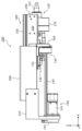
- FIG. 6 is a rear view of the steering device according to the embodiment.
- FIG. 7 is an exploded perspective view of the first rail mechanism according to the embodiment.
- FIG. 8 is an exploded perspective view of the second rail mechanism according to the embodiment.
- FIG. 9 is a cross-sectional view of the first rail mechanism according to the embodiment.
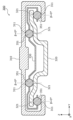
- FIG. 10 is a cross-sectional view of the second rail mechanism according to the embodiment.
- the drawings may be schematic drawings with appropriate emphasis, omission, or proportion adjustment to illustrate the present invention, that is, they may differ from the actual shape, positional relationship, and proportion.
- expressions indicating relative directions or orientations such as parallel and orthogonal may be used, but these expressions strictly include cases where the directions or orientations are not the same.
- two directions are parallel means not only that the two directions are completely parallel, but also substantially parallel, i.e., including a difference of about several percent also means
- FIG. 1 is a schematic diagram showing an overview of the configuration of a steering system 10 according to an embodiment.
- a steering system 10 is a device mounted on a vehicle such as a passenger car, bus, truck, construction machine, or agricultural machine that can switch between a manual operation mode and an automatic operation mode, for example.
- the steering system 10 includes, as shown in FIG. 1, a steering device 100 having a steering member 110 operated by a driver, and a steering mechanism section 102 for steering wheels 710 .
- the steering system 10 reads the rotation angle of the steering member 110 with a sensor or the like in, for example, a manual operation mode, and steers the steerable wheels 710 by reciprocating the shaft body 730 left and right based on signals from the sensor or the like. is.
- a system is called, for example, an SBW (Steer By Wire) system.
- the steering member 110 is attached to a shaft member 121, which is an example of a steering input shaft, and the shaft member 121 is movable. It is rotatably supported on body 130 .
- the movable body 130 is provided with a reaction force generator 125 , and a rotational drive force from the reaction force generator 125 acts on the shaft member 121 .
- a reaction force is applied to steering member 110 when the driver operates steering member 110 .
- the rotational driving force generated by the reaction force generator 125 is also used to synchronize the rotational position of the steering member 110 with the steering angle of the steered wheels 710 .
- the steerable wheels 710 connected to the shaft 730 via the tie rods 711 are moved by the movement of the shaft 730 in the width direction of the vehicle (horizontal direction in FIG. 1). steer.
- the steering actuator 750 operates based on a signal indicating the rotation angle and the like of the steering member 110 transmitted from the steering device 100 .
- the shaft 730 moves in the width direction of the vehicle, and the steerable wheels 710 are steered. That is, the steerable wheels 710 are steered according to the operation of the steering member 110 .
- the steering actuator 750 operates based on a signal or the like transmitted from a computer (not shown) for automatic driving provided in the vehicle.
- the helm 710 steers.
- FIG. 1 illustrates a configuration in which the driving force of the steering actuator 750 is transmitted to the shaft body 730 using a belt. no.
- the driving force of the steering actuator 750 may be transmitted to the shaft body 730 via a pinion gear fixed to the rotating shaft of the steering actuator 750 .
- FIG. 2 is a first perspective view showing the appearance of the steering device 100 according to the embodiment.
- FIG. 3 is a side view of steering device 100 corresponding to FIG.
- FIG. 2 shows the steering device 100 when the movable body 130 is in the normal position, and the approximate shape of the steering member 110 is shown by a chain double-dashed line. 3 to 5, illustration of the steering member 110 is omitted.
- the “normal position” of movable body 130 is the position of movable body 130 for operation of steering member 110 by the driver.
- FIG. 4 is a second perspective view showing the appearance of the steering device 100 according to the embodiment.
- FIG. 4 is a second perspective view showing the appearance of the steering device 100 according to the embodiment.
- FIGS. 4 and 5 are a third perspective view showing the appearance of the steering device 100 according to the embodiment.
- FIGS. 4 and 5 show the steering device 100 when the movable body 130 is in the retracted position.
- the "retracted position" of the movable body 130 is a predetermined position forward of the normal position, and is the position of the movable body 130 when the steering member 110 is moved forward to expand the space in front of the driver. be.
- the steering device 100 includes a movable body 130, a column portion 120 attached to the movable body 130, and a column portion 120 that guides movement of the movable body 130 in the front-rear direction.
- a first rail mechanism 200 and a second rail mechanism 300 are provided.
- the column section 120 has a reaction force generator 125 and a shaft member 121 rotatably supported by the reaction force generator 125 .
- the movable body 130 has a body portion 131 to which the reaction force generating device 125 is fixed, and a nut portion 134 that receives a driving force (propulsive force) in the longitudinal direction.
- the movable body 130 supports the shaft member 121 via the reaction force generator 125 fixed to the movable body 130 .
- the column part 120 moves along with the movement of the movable body 130 .
- the steering member 110 attached to the shaft member 121 also moves along with the movement of the movable body 130 .
- the reaction force generating device 125 is a device that reproduces the force generated in the steering member during driving as a reaction force in a conventional vehicle in which the tires and the steering member are mechanically connected. As shown in FIG. 5 , the reaction force generator 125 has a shaft support portion 126 that supports the shaft member 121 and a reaction force motor 127 that generates rotational driving force to be applied to the shaft member 121 . In this embodiment, as shown in FIGS. 2 and 5, the shaft support portion 126 and the reaction motor 127 are arranged at positions shifted in the width direction of the vehicle (the Y-axis direction in this embodiment). ing. As a result, the size of the reaction force generating device 125 in the longitudinal direction of the vehicle can be made relatively small.
- the rotational driving force of the reaction motor 127 is applied to the shaft member 121 supported by the shaft support portion 126 by, for example, a belt.
- the reaction force generator 125 has a speed reducer that reduces the rotation speed of the reaction force motor 127 and transmits it to the shaft member 121, a sensor that detects the rotation angle of the shaft member 121, and the like. omitted.
- the reaction force generator 125 applies a reaction force to the steering member 110 via the shaft member 121 with the above configuration.
- the reaction force generator 125 can also control the rotational position of the steering member 110 around the steering shaft S.
- the steering axis S is a virtual axis (see FIG. 2, parallel to the X-axis in the present embodiment) passing through the center of rotation of the shaft member 121 and extending in the longitudinal direction of the vehicle.
- the "front-back direction of the vehicle” generally refers to a direction parallel to the straight-ahead direction of the vehicle, a direction in which the backrest of the driver's seat and the steering device 100 are arranged, or a direction connecting the front and rear parts of the vehicle.
- the position of the steering member 110 relative to the driver's upper body is "forward".
- the steering shaft S which is the center of rotation of the shaft member 121 and the steering member 110, does not need to be strictly aligned with the "front-rear direction of the vehicle.”
- the steering shaft S may be tilted with respect to the horizontal direction so that the steering member 110 faces slightly upward when the vehicle is stopped on a horizontal road surface.
- the steering member 110 moves in the longitudinal direction of the vehicle
- the trajectory of the movement does not need to strictly match "the longitudinal direction of the vehicle.”
- the steering member 110 may It is expressed as "moving in the forward and backward direction of the This applies regardless of whether the trajectory of movement of the steering member 110 is straight, curved, or the like.
- the "front-back direction of the vehicle” is hereinafter simply referred to as the "front-back direction”.
- the steering member 110 is a member manually operated by the driver, and is detachably attached to the axial end of the shaft member 121 (the end on the driver's side).
- the steering member 110 rotates about the steering shaft S, and the shaft member 121 connected to the steering member 110 also rotates about the steering shaft S accordingly.
- one or more steerable wheels 710 of the vehicle are steered based on the amount of rotation, etc., as described above.
- a winker lever (not shown) or the like is arranged between the steering member 110 and the reaction force generator 125, and the driver can also operate the winker lever or the like when operating the steering member 110.
- the shape and size of steering member 110 are not limited to the shape and size shown in FIG. The shape and size of the steering member 110 can be appropriately determined according to the size and shape of the steering device 100, for example.
- the column section 120 to which the steering member 110 is attached is fixed to the movable body 130, and the movable body 130 is movable in the longitudinal direction by the first rail mechanism 200 and the second rail mechanism 300.
- the first rail mechanism 200 and the second rail mechanism 300 are fixed to a bracket 500, and the bracket 500 is fixed to a vehicle (not shown). That is, the first rail mechanism 200 and the second rail mechanism 300 are fixed to the vehicle via the brackets 500 .
- the movable body 130 moves in the longitudinal direction relative to the vehicle while being guided by the first rail mechanism 200 and the second rail mechanism 300 . As a result, the movable body 130 can move between a normal position (see FIGS.
- the storage position of the movable body 130 is set in any of the interior spaces of the dashboard located in front of the driver.
- the movable body 130 can move forward until the rear end of the shaft member 121 of the column section 120 reaches a predetermined position below the bracket 500, as shown in FIG. can.
- the space between the first rail mechanism 200 and the second rail mechanism 300 in the width direction of the vehicle can be used as a housing area for the steering member 110 . This will be described later with reference to FIG.
- the steering device 100 includes a driving device 140 for driving the movable body 130 to move in the front-rear direction.
- the driving device 140 has a moving actuator 141, a feed screw 145, and a transmission mechanism 142, as shown in FIGS.
- the moving actuator 141 and the transmission mechanism 142 are fixed to a mounting member 510 fixed to the front end of the bracket 500 .
- Feed screw 145 has a front end rotatably supported by mounting member 510 and a rear end rotatably supported by shaft support member 520 fixed to the rear end of bracket 500 .
- drive device 140 is fixed to bracket 500 .
- the rotational force generated by the movement actuator 141 is transmitted to the feed screw 145 via the transmission mechanism 142, thereby rotating the feed screw 145.
- the feed screw 145 is screwed into a nut portion 134 fixed to the movable body 130, thereby moving the movable body 130 in the front-rear direction.
- the movable body 130 moves while being guided by a first rail mechanism 200 and a second rail mechanism 300 (hereinafter also referred to as two rail mechanisms (200, 300)).
- the movable body 130 to which the column section 120 is fixed is supported by the two rail mechanisms (200, 300) and guided in forward and backward movement.
- the two rail mechanisms (200, 300) are arranged at different positions in the width direction of the vehicle, thereby allowing the movable body 130 to move in the longitudinal direction while being stably supported.
- the configuration and operation of the steering device 100 will be described in detail, focusing on the configuration and operation of the two rail mechanisms (200, 300), with reference to FIGS. 6 to 10.
- FIG. 6 is a diagram (rear view) of the steering device 100 according to the embodiment as viewed from the driver's side.
- FIG. 6 in order to clearly show the configuration of the two rail mechanisms (200, 300), illustration of the driving device 140, the shaft support member 520, etc. is omitted, and the steering member 110 is roughly shaped into two points. It is illustrated with a dashed line.
- FIG. 7 is an exploded perspective view of the first rail mechanism 200 according to the embodiment.
- FIG. 8 is an exploded perspective view of the second rail mechanism 300 according to the embodiment.
- FIG. 9 is a cross-sectional view of the first rail mechanism 200 according to the embodiment. In FIG. 9, a section taken along the line IX-IX in FIG. 7 is illustrated.
- FIG. 10 is a cross-sectional view of the second rail mechanism 300 according to the embodiment.
- FIG. 10 shows a section taken along the line XX in FIG.
- the movable body 130 has two rail mechanisms (200, 300), each of which is a linear motion guide, at positions spaced apart in the width direction (Y-axis direction) of the vehicle. are placed.
- Each of the two rail mechanisms (200, 300) is configured by combining long rails in the front-rear direction.
- the first rail mechanism 200 includes a first fixed rail 210, a first moving rail 220 slidably attached to the first fixed rail 210, It has a plurality of first rolling element rows 250 .
- the first rolling element row 250 includes a plurality of first rolling elements 251 arranged in the moving direction (X-axis direction) of the first moving rail 220 with respect to the first fixed rail 210 .
- the first rolling element 251 is arranged between the first raceway surface 211 of the first fixed rail 210 and the second raceway surface 221 of the first moving rail 220 .
- the first fixed rail 210 has two first track surfaces 211 and the first moving rail 220 has two second track surfaces 221, as shown in FIGS.
- the first fixed rail 210 and the first moving rail 220 are combined so that each of the two second raceway surfaces 221 faces the first raceway surface 211 in the Z-axis direction. That is, the first rail mechanism 200 has two sets of the first raceway surface 211 and the second raceway surface 221 facing each other in the Z-axis direction.
- a first rolling element row 250 is arranged between the first raceway surface 211 and the second raceway surface 221 in each of the two sets of the first raceway surface 211 and the second raceway surface 221 .
- the first raceway surface 211 is a curved surface (inner surface of the groove) that is elongated in the X-axis direction and recessed in a direction away from the second raceway surface 221 .
- the second raceway surface 221 is a curved surface (inner surface of the groove) that is elongated in the X-axis direction and recessed in a direction away from the first raceway surface 211 .
- Each of the plurality of first rolling elements 251 included in the first rolling element row 250 is a metal sphere (bearing ball) in the present embodiment.
- each of the two first rolling element rows 250 arranged between the first fixed rail 210 and the first moving rail 220 includes two spacers 251a (see FIG. 7).
- the spacer 251 a is a spherical body having a diameter that is the same as or slightly smaller than the diameter of the plurality of first rolling elements 251 included in the first rolling element row 250 .
- Each of the plurality of first rolling elements 251 included in the first rolling element row 250 is rotatable by a plate-like retainer 230 arranged between the first fixed rail 210 and the first moving rail 220. is held in Each of the plurality of first rolling elements 251 is held by the retainer 230 and rolls while maintaining their relative positions.
- the retainer 230 has a plurality of first rolling element pockets (openings) 231a for holding the first rolling elements 251 and a plurality of spacer pockets (openings) 231b for holding the spacers 251a. have.
- the diameter of the spacer pocket 231b is smaller than the diameter of the first rolling element pocket 231a.
- a plurality of spacers 251a included in the first row of rolling elements 250 has two hemispheres, and these two hemispheres sandwich the periphery of the spacer pocket 231b of the retainer 230 in the vertical (Z-axis) direction. It is fixed to the retainer 230 by joining the two hemispheres.
- the retainer 230 is fixed at a position that passes through the center position of the spacer 251a, so that the Z-axis direction position of the retainer 230 with respect to the first raceway surface 211 and the second raceway surface 221 is positioned at the Z-axis direction center.
- the plurality of first rolling elements 251 included in the first rolling element row 250 can roll appropriately.
- At least two spacers 251 a are required for each of the two first rolling element rows 250 .
- the two hemispheres of the spacer 251a form a convex portion on one facing surface and a concave portion on the other facing surface, and are joined by concave-convex press-fitting, but the present invention is not limited to this.
- the arrangement order of the first rolling element pocket 231a and the spacer pocket 231b of the retainer 230 can be appropriately set.
- first fixed rail 210 is fixed to the bracket 500 as shown in FIGS. That is, first fixed rail 210 is fixed to the vehicle via bracket 500 .
- the first moving rail 220 is fixed to the body portion 131 of the movable body 130, as shown in FIG.
- the movable body 130 and the column part 120 fixed to the movable body 130 move in the front-rear direction along with the front-rear direction of the first moving rail 220 .
- first rolling element rows 250 are arranged, thereby Moves forward and backward smoothly.
- the two first rolling element rows 250 move back and forth with respect to the first fixed rail 210 and the first moving rail 220 while being held by the retainer 230 .
- a stopper that contacts the retainer 230 is arranged on each of the first fixed rail 210 and the first moving rail 220 . This prevents the two first rolling element rows 250 and the retainer 230 from coming off the first fixed rail 210 and the first moving rail 220 . Specifically, as shown in FIG.
- first fixed stoppers 215 and 216 are arranged on the first fixed rail 210 at positions separated from each other in the X-axis direction.
- First movement stoppers 225 and 226 are arranged on the first movement rail 220 at positions separated from each other in the X-axis direction.
- retainer 230 is movable only between first fixed stopper 215 and first fixed stopper 216 with respect to first fixed rail 210 .
- the retainer 230 is movable with respect to the first travel rail 220 only between the first travel stop 225 and the first travel stop 226 .
- the retainer 230 does not drop off from the first fixed rail 210 and the first moving rail 220 even when the first moving rail 220 moves in the front-rear direction and moves in the front-rear direction.
- the two first rolling element rows 250 held by the retainer 230 do not fall off the first fixed rail 210 and the first moving rail 220 either.
- the first moving rail 220 cannot move backward from its position.
- the first fixed stopper 215 and the first moving stopper 226 also function as a restricting member that restricts the rearward movement of the first moving rail 220 (removing backward from the first stationary rail 210).
- the retainer 230 is sandwiched between the first fixed stopper 216 on the front end side of the first fixed rail 210 and the first moving stopper 225 on the rear end side of the first moving rail 220, the first moving rail 220 cannot move forward from its position.
- the first fixed stopper 216 and the first moving stopper 225 also function as restricting members that restrict forward movement of the first moving rail 220 (forward removal from the first stationary rail 210).
- the second rail mechanism 300 includes a second fixed rail 310 and a second moving rail 320 slidably attached to the second fixed rail 310. , and a plurality of second rolling element rows 350 .
- the second rolling element row 350 includes a plurality of second rolling elements 351 arranged in the moving direction (X-axis direction) of the second moving rail 320 with respect to the second fixed rail 310 .
- the second rolling element row 350 is arranged between the third raceway surface 311 of the second fixed rail 310 and the fourth raceway surface 321 of the second moving rail 320 .
- the second fixed rail 310 has four third track surfaces 311 and the second moving rail 320 has four fourth track surfaces 321, as shown in FIGS.
- Each of these eight track surfaces is formed by a portion of the planar portion of second fixed rail 310 or second moving rail 320 .
- the second fixed rail 310 and the second moving rail 320 are combined so that each of the four fourth track surfaces 321 faces the third track surface 311 in the Z-axis direction. That is, the second rail mechanism 300 has four sets of the third raceway surface 311 and the fourth raceway surface 321 facing each other in the Z-axis direction.
- a second rolling element row 350 is arranged between the third raceway surface 311 and the fourth raceway surface 321 in each of the four sets of the third raceway surface 311 and the fourth raceway surface 321 .
- the second rail mechanism 300 has four second rolling element rows 350 . As shown in FIG.
- each of the third raceway surface 311 and the fourth raceway surface 321 is a plane elongated in the X-axis direction.
- Each of the plurality of second rolling elements 351 is a metallic sphere (bearing ball), like the first rolling element 251, in the present embodiment.
- two spacers 351a are included in each of the two second rolling element rows 350 arranged below the second moving rail 320 (Z-axis negative direction).
- the spacer 351 a is a spherical body having a diameter that is the same as or slightly smaller than the diameter of the plurality of second rolling elements 351 included in the second rolling element row 350 .
- Each of the plurality of second rolling elements 351 included in the second rolling element row 350 is rotatable by a plate-like retainer 330 arranged between the second fixed rail 310 and the second moving rail 320. is held in Each of the plurality of second rolling elements 351 is held by the retainer 330 to roll while maintaining their relative positions.
- the retainer 330 has a plurality of second rolling element pockets (openings) 331 for holding the second rolling elements 351 and a plurality of spacer pockets (openings) for holding the spacers 351a. are doing.
- a plurality of spacer pockets are provided on the negative side of the retainer 330 along the Z axis.
- the diameter of the spacer pocket is smaller than the diameter of the second rolling element pocket 331 .
- the plurality of spacers 351a included in the second row of rolling elements 350 has two hemispheres, and these two hemispheres sandwich the periphery of the spacer pocket of the retainer 330 in the vertical (Z-axis) direction.
- the retainer 330 It is fixed to the retainer 330 by joining the two hemispheres.
- the retainer 330 is fixed at a position that passes through the center position of the spacer 351a, so that the Z-axis direction position of the retainer 330 with respect to the third raceway surface 311 and the fourth raceway surface 321 is positioned at the Z-axis direction center.
- the plurality of second rolling elements 351 included in the second rolling element row 350 can roll appropriately.
- At least two spacers 351a may be provided for each of the two second rolling element rows 350 out of the four second rolling element rows 350 shown in FIG.
- Each of the four second rolling element rows 350 may include at least two spacers 351a.
- the two hemispheres of the spacer 351a form a convex portion on one facing surface and a concave portion on the other facing surface, and are joined by concave-convex press-fitting, but the present invention is not limited to this.
- the arrangement order of the second rolling element pocket 331 and the spacer pocket of the retainer 330 can be appropriately set.
- the second fixed rail 310 is fixed to the mounting surface of the bracket 500 parallel to the width direction (Y-axis direction) of the vehicle, as shown in FIGS. ing. That is, second fixed rail 310 is fixed to the vehicle via bracket 500 .
- the second moving rail 320 is fixed to the movable body 130 as shown in FIG. That is, the movable body 130 is fixed to the first moving rail 220 and the second moving rail 320 .
- the movable body 130 and the column section 120 fixed to the movable body 130 move in the front-rear direction as the first moving rail 220 and the second moving rail 320 move in the front-rear direction.
- each of the second fixed rail 310 and the second moving rail 320 is provided with a stopper that abuts on the retainer 330, so that the four second rolling element rows 350 and the retainer 330 are connected to the second fixed rail. Falling off from 310 and second moving rail 320 is suppressed. Specifically, as shown in FIG.
- second fixed stoppers 315 and 316 are arranged on the second fixed rail 310 at positions separated from each other in the X-axis direction.
- Second movement stoppers 325 and 326 are arranged on the second movement rail 320 at positions separated from each other in the X-axis direction.
- the retainer 330 is movable only between the second fixed stopper 315 and the second fixed stopper 316 with respect to the second fixed rail 310 .
- the retainer 330 is movable with respect to the second movement rail 320 only between the second movement stop 325 and the second movement stop 326 .
- the retainer 330 does not fall off the second fixed rail 310 and the second moving rail 320 , so the four second rolling element rows 350 do not fall off the second fixed rail 310 and the second moving rail 320 .
- the second fixed stopper 315 and the second moving stopper 326 sandwich the retainer 330 in the front-rear direction, thereby moving the second moving rail 320 rearward (rearward from the second fixed rail 310). It also functions as a restricting member that restricts slipping out.
- the second fixed stopper 316 and the second moving stopper 325 sandwich the retainer 330 in the front-rear direction, so that the second moving rail 320 moves forward (gets out of the second fixed rail 310 forward). It also functions as a regulating member that regulates the
- the longitudinal movement of the first moving rail 220 with respect to the first fixed rail 210 is driven by the driving device 140 as described above.
- a detection result that the first moving rail 220 or the second moving rail 320 is stopped by a stopper may be used for the control of the driving device 140 .
- a control device (not shown) that controls the driving device 140 controls the movement of the first moving rail 220 by stopping.
- An increase in the load torque of the actuator 141 is detected.
- the control device stops the operation of the movement actuator 141 when detecting the increase in the load torque. It is not essential to use stoppers to stop the first moving rail 220 and the second moving rail 320 .
- the control device may control the driving device 140 based on the detection result of a sensor that detects the position of the movable body 130, thereby stopping the movement of the first moving rail 220 and the second moving rail 320. .
- the steering device 100 includes the shaft member 121 which is a steering input shaft to which the steering member 110 is attached, the movable body 130, the first rail mechanism 200 and the second rail mechanism 300.
- the movable body 130 rotatably supports the shaft member 121 .
- the first rail mechanism 200 and the second rail mechanism 300 guide the movement of the movable body 130 in the longitudinal direction of the vehicle.
- the first rail mechanism 200 and the second rail mechanism 300 are arranged at different positions in the width direction of the vehicle.
- the first rail mechanism 200 is arranged at a position different from the shaft member 121 in the width direction of the vehicle
- the second rail mechanism 300 is arranged at a position above the shaft member 121 in the vertical direction of the vehicle. (See Figure 6).
- the steering member 110 operated by the driver is supported by the movable body 130 via the shaft member 121 .
- the movable body 130 is movably supported in the longitudinal direction by two rail mechanisms (200, 300) arranged in the width direction of the vehicle when viewed in the vertical direction of the vehicle.
- the first rail mechanism 200 is positioned apart from the shaft member 121 in the width direction of the vehicle
- the second rail mechanism 300 is positioned above the shaft member 121 in the vertical direction of the vehicle. Therefore, when viewed from the shaft member 121 , movement in the left-right direction (the width direction of the vehicle) is mainly restricted by the first rail mechanism 200 , and movement in the vertical direction is mainly restricted by the second rail mechanism 300 .
- the two rail mechanisms (200, 300)
- the movable body 130 is stably supported. That is, the steering device 100 has relatively high rigidity for supporting the movable body 130, and as a result, the stability of supporting the steering member 110 attached to the shaft member 121 is improved.
- the second rail mechanism 300 is arranged at a position above the shaft member 121 in the vertical direction of the vehicle. Therefore, the problem of interference between the rail mechanism and other members such as the driver's legs or the brake pedal, which occurs when the rail mechanism is arranged under the steering device 100, does not occur.
- the steering device 100 according to the present embodiment is a steering device that can widen the space in front of the driver and stably support the steering member 110 .
- the first rail mechanism 200 and the second rail mechanism 300 are configured as follows.
- the first rail mechanism 200 includes a first fixed rail 210 fixed to the vehicle, a first moving rail 220 slidably attached to the first fixed rail 210, and a plurality of first rolling element rows 250.
- the first fixed rail 210 has a double-row first raceway surface 211 .
- the first moving rail 220 has a double-row second track surface 221 .
- the plurality of first rolling element rows 250 are arranged between the double-row first raceway surface 211 and the double-row second raceway surface 221 .
- Each of the plurality of first rolling element rows 250 includes a plurality of rollable first rolling elements 251 .
- the second rail mechanism 300 includes a second fixed rail 310 fixed to the vehicle, a second moving rail 320 slidably attached to the second fixed rail 310, and a plurality of second rolling element rows 350.
- the second fixed rail 310 has a double-row third raceway surface 311 .
- the second moving rail 320 has a double-row fourth track surface 321 .
- the plurality of second rolling element rows 350 are arranged between the double-row third raceway surface 311 and the double-row fourth raceway surface 321 .
- Each of the plurality of second rolling element rows 350 includes a plurality of rollable second rolling elements 351 .
- the plurality of first rolling elements 251 of the first rolling element row 250 arranged between the first raceway surface 211 and the second raceway surface 221 roll.
- the first moving rail 220 slides with respect to the first fixed rail 210 .
- a plurality of combinations of the first raceway surface 211, the second raceway surface 221, and the first rolling element row 250 arranged therebetween are arranged. Therefore, the rigidity of the first rail mechanism 200 as a whole is ensured, and the smoothness of the expansion and contraction operation is also ensured.
- the second rail mechanism 300 is the same, and as a configuration for sliding the second moving rail 320 with respect to the second fixed rail 310, a third track surface 311, a fourth track surface 321, and a It has a plurality of combinations of the second rolling element rows 350 . Thereby, the rigidity of the second rail mechanism 300 is ensured, and the smoothness of the expansion and contraction operation is also ensured. Therefore, according to the steering device 100 having such two rail mechanisms (200, 300), the steering member 110 can be supported more stably.
- the contact angles of the rolling elements of the first rail mechanism 200 and the second rail mechanism 300 are different from each other. Specifically, as shown in FIGS. 9 and 10, the contact angle ⁇ of each of the plurality of first rolling elements 251 with respect to the first raceway surface 211 and the second raceway surface 221 and the contact angle ⁇ of each of the plurality of second rolling elements 351 , the contact angles ⁇ with respect to the third raceway surface 311 and the fourth raceway surface 321 are different from each other.
- the original moving direction (X-axis direction) of the first moving rail 220 and the second moving rail 320 is The direction in which it is difficult to move (displace) in the direction orthogonal to .
- the movement directions of the first movement rail 220 and the second movement rail 320, both connected to the movable body 130 are not strictly parallel, the movement of one may be constrained by the other.
- the two rail mechanisms (200, 300) have different contact angles of the rolling elements. Therefore, the telescopic motion of one of the two rail mechanisms (200, 300) is less likely to interfere with the telescopic motion of the other.
- the total number of contact points of each of the plurality of first rolling elements 251 with respect to the first raceway surface 211 and the second raceway surface 221 is 3 or more.
- the first rolling element 251 rolling between the first fixed rail 210 and the first moving rail 220 is three It contacts with the raceway surfaces (the first raceway surface 211 and the second raceway surface 221) in the above directions. Therefore, the first moving rail 220 is less likely to move (displace) in the three or more directions in the direction orthogonal to the moving direction (X-axis direction). That is, the first rail mechanism 200 has relatively high load resistance in the three or more directions.
- FIG. 9 In the first rail mechanism 200 according to the present embodiment, when focusing on one first rolling element 251, as shown in FIG. is placed between Both the first raceway surface 211 and the second raceway surface 221 are inner surfaces of grooves of the same shape that can accommodate a portion of the first rolling element 251 .
- this groove has a shape called, for example, a Gothic arc groove.
- each of the first raceway surface 211 and the second raceway surface 221 is formed with the first rolling element 251, which is a sphere. They are in contact at two points.
- the contact angle of the first rolling element 251 with respect to the first raceway surface 211 and the second raceway surface 221 is ⁇ in FIG.
- the first rolling element 251 is sandwiched between the first fixed rail 210 and the first moving rail 220 in the Z-axis direction, and the first moving rail 220 moves in the X-axis direction.
- the contact angle ⁇ is the angle between a straight line passing through the center of the first rolling element 251 and parallel to the Z-axis and a straight line connecting the center and the contact point. is, for example, 45°. Therefore, even if an external force is applied to the first moving rail 220 connected to the movable body 130 in either the width direction of the vehicle (Y-axis direction) or the vertical direction of the vehicle (Z-axis direction). , the first rail mechanism 200 can suppress the movement of the first moving rail 220 against the external force.
- the contact angle ⁇ of the second rolling element 351 with respect to the third raceway surface 311 and the fourth raceway surface 321 is 0°. .
- the third raceway surface 311 is a plane formed by a portion of the inner surface of the second fixed rail 310 and extending in the X-axis direction.
- the fourth raceway surface 321 is a plane formed by a portion of the surface of the second moving rail 320 and extending in the X-axis direction.
- each of the third raceway surface 311 and the fourth raceway surface 321 is in contact with the spherical second rolling element 351 at one point in a cross section perpendicular to the extending direction of the raceway surface (X-axis direction).
- the second rolling element 351 is sandwiched between the second fixed rail 310 and the second moving rail 320 in the Z-axis direction, and the second moving rail 320 moves in the X-axis direction.
- the contact angle ⁇ of the second rolling element 351 with the third raceway surface 311 and the fourth raceway surface 321 is defined by a straight line passing through the center of the second rolling element 351 and parallel to the Z-axis, and a contact point between the center and the contact point.
- the contact angle ⁇ is 0°. Therefore, when an external force in the vertical direction (Z-axis direction) of the vehicle is applied to the second moving rail 320 connected to the movable body 130, the second rail mechanism 300 resists the external force and The vertical movement of the two-moving rail 320 can be suppressed. On the other hand, when an external force is applied to the second moving rail 320 in the width direction (Y-axis direction) of the vehicle, the second rail mechanism 300 moves the vehicle within a predetermined range of the second moving rail 320. Allows lateral movement.
- first rail mechanism 200 can resist the external force in the width direction of the vehicle, as described above. That is, the movement of the movable body 130 in the width direction of the vehicle is mainly restricted by the first rail mechanism 200 .
- two rail mechanisms (200, 300) that both extend and contract in the X-axis direction are arranged in parallel, and the movable body 130 is attached to these two rail mechanisms (200, 300).
- a structure for retracting and retracting the body 130 is employed. Therefore, for example, if the two rail mechanisms (200, 300) are not strictly parallel, the sliding load (mechanical resistance during sliding) on the two rail mechanisms (200, 300) increases. As a result, there is a possibility that the movable body 130 cannot smoothly move between the normal position and the retracted position.
- second rail mechanism 300 has a structure that allows movement (displacement) of second moving rail 320 in the width direction of the vehicle, as described above.
- the second moving rail 320 can be displaced in the width direction of the vehicle. , an increase in the sliding load of the two rail mechanisms (200, 300) is suppressed. As a result, the movable body 130 can be smoothly moved between the normal position and the retracted position. Furthermore, for example, since strictness is not required for arranging the first rail mechanism 200 and the second rail mechanism 300 in parallel, the work of attaching the first rail mechanism 200 and the second rail mechanism 300 to the bracket 500 is reduced. Efficient. As a result, the manufacturing efficiency of the steering device 100 can be improved or the manufacturing cost can be suppressed.
- the first rail mechanism 200 has two first rolling element rows 250, and the second rail mechanism 300 has three or more second rolling element rows 350.
- the number of the first rolling element rows 250 that smoothly slide the first moving rail 220 relative to the first fixed rail 210 is two. Therefore, for example, the pitch error (deviation in raceway row interval) that tends to occur when the number of the first rolling element rows 250 is three or more is less likely to occur. It is difficult for the first rail mechanism 200 to extend and retract due to the overlapping of the two.
- the number of the second rolling element rows 350 for smoothly sliding the second moving rail 320 with respect to the second fixed rail 310 is three or more (four in the present embodiment). This improves the load resistance of the second rail mechanism 300 that supports the movable body 130 to which the column portion 120 is fixed in a suspended manner (from above). This is advantageous for stably supporting the steering member 110 supported by the movable body 130 .
- first rail mechanism 200 and the second rail mechanism 300 which are arranged at different positions in the width direction of the vehicle, are arranged apart from each other as shown in FIGS. 5 and 6, for example. ing.
- the steering device 100 when the steering device 100 is viewed from the rear (the positive direction of the X axis), there is a space between the first rail mechanism 200 and the second rail mechanism 300 that is created by separating them. do.
- a grip portion 110b which is a portion of the steering member 110 that is gripped by the driver, is accommodated.
- the space between the first rail mechanism 200 and the second rail mechanism 300 can be used as a housing area for the steering member 110 .
- the steering member 110 can be moved to a predetermined position below the bracket 500 (see FIG. 5).
- the member accommodated in the space between the first rail mechanism 200 and the second rail mechanism 300 is not limited to the steering member 110, and a turn signal lever or the like (not shown) included in the column portion 120 is accommodated in the space. good too.
- the second rail mechanism 300 is arranged at a position above the shaft member 121 in the vertical direction and not directly above the shaft member 121. .
- the space located right above the shaft member 121 and on the side of the second rail mechanism 300 in the width direction of the vehicle can be used as a storage area for the steering member 110 and the column portion 120 .
- the hub portion 110a of the steering member 110 which is the portion connected to the shaft member 121
- the second rail mechanism 300 is not arranged directly above the shaft member 121, when the movable body 130 is moved to the storage position, the hub portion 110a and the second rail mechanism 300 are separated from each other. can be prevented from interfering.
- the member accommodated in the space directly above the shaft member 121 is not limited to the steering member 110, and a turn signal lever or the like (not shown) included in the column portion 120 may be accommodated in the space.
- each of the first rail mechanism 200 and the second rail mechanism 300 may have one or more rolling element rows. That is, the first rail mechanism 200 can slide the first moving rail 220 with respect to the first fixed rail 210 as long as it has at least one first rolling element row 250 .
- the second rail mechanism 300 similarly has at least one second row of rolling elements 350 so that the second moving rail 320 can slide relative to the second fixed rail 310 .
- the second rail mechanism 300 may have only one second rolling element row 350 between the inner surface of the second fixed rail 310 and the upper surface of the second moving rail 320 . That is, the number of the second rolling element rows 350 in the second rail mechanism 300 may be three.
- the second row of rolling elements 350 arranged along the upper surface of the second moving rail 320 may be arranged in the central portion of the second fixed rail 310 and the second moving rail 320 in the Y-axis direction. This is preferable from the viewpoint of realizing stable sliding motion of the moving rail 320 .
- the number of rolling element rows possessed by the first rail mechanism 200 and the second rail mechanism 300 is, for example, the specifications required for the first rail mechanism 200 and the second rail mechanism 300 (necessary expansion and contraction length, members to be supported ( It may be appropriately determined according to the weight or size of the movable body 130 and the column portion 120, etc.).
- the number of contact points of the first rolling element 251 with the raceway surface may be two, as in the second rail mechanism 300.
- a rail mechanism having the same structure as that of the second rail mechanism 300 is arranged so that its thickness direction (the alignment direction of the fixed rail and the movable rail) faces the width direction (Y-axis direction) of the vehicle, and the first rail mechanism 200 can be placed in the position of
- the moving rail is structurally allowed to move (displace) in the vertical direction of the vehicle.
- the rail mechanism can resist the external force in the vertical direction of the vehicle, so the movement of the movable body 130 in the vertical direction of the vehicle is mainly restricted by the rail mechanism. .
- the first rolling element 251 and the second rolling element 351 may be different types of rolling elements from the bearing balls.
- a bearing roller may be employed as at least one of the first rolling element 251 and the second rolling element 351, for example.
- the material forming the first rolling element 251 and the second rolling element 351 is not limited to metal. At least one of the first rolling element 251 and the second rolling element 351 may be made of resin, for example.
- the rail mechanisms included in the steering device 100 need not be limited to the first rail mechanism 200 and the second rail mechanism 300 only.
- a third rail mechanism connected to the movable body 130 may be arranged on the right side of the movable body 130 in FIG.
- the third rail mechanism may be fixed to the vehicle via bracket 500 or another member, or may be fixed directly to the vehicle.
- the steering device 100 may include at least the first rail mechanism 200 and the second rail mechanism 300 as rail mechanisms that support the movable body 130 so as to be movable in the longitudinal direction.
- the steering device 100 may be further provided with a rail mechanism.
- the first rail mechanism 200 and the second rail mechanism 300 may have an intermediate rail that is arranged between the fixed rail and the moving rail and that is slidably arranged with each of the fixed rail and the moving rail. As a result, the stretchable lengths of the first rail mechanism 200 and the second rail mechanism 300 are increased.
- the first rail mechanism 200 and the second rail mechanism 300 do not have to be separated in the vehicle width direction (Y-axis direction). That is, the first rail mechanism 200 and the second rail mechanism 300 may be arranged in contact with each other in the width direction of the vehicle.
- the distance between the first rail mechanism 200 and the second rail mechanism 300 in the width direction of the vehicle may be determined according to the sizes of the movable body 130 and the column portion 120 in the width direction of the vehicle.
- the steering device 100 may further include a tilt mechanism that changes the tilt of the steering device 100 in the vertical direction.
- the tilt mechanism section for example, changes the inclination of the bracket 500 in the vertical direction. Thereby, the vertical position of the steering member 110 can be adjusted according to the intention of the driver.
- the driving device 140 may drive the movement of the movable body 130 by a method different from the feed screw method.
- the driving device 140 may drive the front-rear movement of the movable body 130 by, for example, expanding and contracting a rod fixed to the movable body 130 or moving the front-rear direction.
- the steering device 100 does not have to include the driving device 140 .
- the driver may manually move the steering member 110 forward and backward, that is, move the movable body 130 between the normal position and the retracted position. Even in this case, according to the steering device 100 of the present embodiment, the steering member 110 moves forward and backward while the steering member 110 is stably supported.
- the movable body 130 need not be separate from the column section 120.
- the pedestal may function as the movable body 130 that moves in the front-rear direction while being guided by the first rail mechanism 200 and the second rail mechanism 300. good.
- the present invention is useful as a steering device that can expand the space in front of the driver. Therefore, it can be used for vehicles equipped with wheels or track surfaces, such as passenger cars, buses, trucks, agricultural machines, construction machines, etc., which can be operated manually and automatically.
- Steering system 100: Steering device, 102: Steering mechanism, 110: Steering member, 110a: Hub, 110b: Grip, 120: Column, 121: Shaft member, 125: Reaction force generator, 126 : shaft support portion, 127: reaction force motor, 130: movable body, 131: body portion, 134: nut portion, 140: drive device, 141: movement actuator, 142: transmission mechanism portion, 145: feed screw, 200: First Rail Mechanism 210: First Fixed Rail 211: First Track Surface 215, 216: First Fixed Stopper 220: First Moving Rail 221: Second Track Surface 225, 226: First Moving Stopper , 230, 330: retainer, 231a: first rolling element pocket, 231b: spacer pocket, 250: first rolling element row, 251: first rolling element, 251a, 351a: spacer, 300: second rail mechanism, 310: second fixed rail, 311: third raceway surface, 315, 316: second fixed stopper, 320: second
Landscapes
- Engineering & Computer Science (AREA)
- Mechanical Engineering (AREA)
- General Engineering & Computer Science (AREA)
- Chemical & Material Sciences (AREA)
- Combustion & Propulsion (AREA)
- Transportation (AREA)
- Bearings For Parts Moving Linearly (AREA)
Priority Applications (6)
| Application Number | Priority Date | Filing Date | Title |
|---|---|---|---|
| PCT/JP2021/047030 WO2023119365A1 (ja) | 2021-12-20 | 2021-12-20 | ステアリング装置 |
| US18/713,361 US12371092B2 (en) | 2021-12-20 | 2022-08-12 | Steering device |
| CN202280082156.1A CN118401427A (zh) | 2021-12-20 | 2022-08-12 | 转向装置 |
| EP22910447.6A EP4454975A4 (en) | 2021-12-20 | 2022-08-12 | STEERING DEVICE |
| PCT/JP2022/030735 WO2023119719A1 (ja) | 2021-12-20 | 2022-08-12 | ステアリング装置 |
| JP2023569050A JP7790450B2 (ja) | 2021-12-20 | 2022-08-12 | ステアリング装置 |
Applications Claiming Priority (1)
| Application Number | Priority Date | Filing Date | Title |
|---|---|---|---|
| PCT/JP2021/047030 WO2023119365A1 (ja) | 2021-12-20 | 2021-12-20 | ステアリング装置 |
Publications (1)
| Publication Number | Publication Date |
|---|---|
| WO2023119365A1 true WO2023119365A1 (ja) | 2023-06-29 |
Family
ID=86901568
Family Applications (2)
| Application Number | Title | Priority Date | Filing Date |
|---|---|---|---|
| PCT/JP2021/047030 Ceased WO2023119365A1 (ja) | 2021-12-20 | 2021-12-20 | ステアリング装置 |
| PCT/JP2022/030735 Ceased WO2023119719A1 (ja) | 2021-12-20 | 2022-08-12 | ステアリング装置 |
Family Applications After (1)
| Application Number | Title | Priority Date | Filing Date |
|---|---|---|---|
| PCT/JP2022/030735 Ceased WO2023119719A1 (ja) | 2021-12-20 | 2022-08-12 | ステアリング装置 |
Country Status (5)
| Country | Link |
|---|---|
| US (1) | US12371092B2 (https=) |
| EP (1) | EP4454975A4 (https=) |
| JP (1) | JP7790450B2 (https=) |
| CN (1) | CN118401427A (https=) |
| WO (2) | WO2023119365A1 (https=) |
Cited By (1)
| Publication number | Priority date | Publication date | Assignee | Title |
|---|---|---|---|---|
| DE102024108899A1 (de) * | 2024-03-28 | 2025-10-02 | Audi Aktiengesellschaft | Teleskoplenksäule für eine Cockpitanordnung eines Kraftfahrzeugs sowie entsprechende Cockpitanordnung |
Families Citing this family (1)
| Publication number | Priority date | Publication date | Assignee | Title |
|---|---|---|---|---|
| WO2025004208A1 (ja) * | 2023-06-28 | 2025-01-02 | 株式会社ジェイテクト | ステアリング装置 |
Citations (2)
| Publication number | Priority date | Publication date | Assignee | Title |
|---|---|---|---|---|
| US20190016365A1 (en) * | 2017-07-11 | 2019-01-17 | Nio Usa, Inc. | Body mounted sliding steering column with offset feedback actuator |
| JP2021046001A (ja) * | 2019-09-17 | 2021-03-25 | アイシン精機株式会社 | 車両のステアリング装置 |
Family Cites Families (24)
| Publication number | Priority date | Publication date | Assignee | Title |
|---|---|---|---|---|
| US3904254A (en) * | 1973-06-14 | 1975-09-09 | Magnus F Hagen | Means for positioning ball retainer for telescoping ball bearing slide mechanisms in relationship to open or closed position of same |
| US5737971A (en) * | 1996-08-05 | 1998-04-14 | General Motors Corporation | Motor vehicle steering column |
| DE10250663A1 (de) * | 2002-10-31 | 2004-05-13 | Ina-Schaeffler Kg | Lager einer teleskopischen Verbindung |
| JP4190905B2 (ja) * | 2003-02-06 | 2008-12-03 | 日本精工株式会社 | 車両用ステアリング装置 |
| US20060053933A1 (en) | 2004-08-30 | 2006-03-16 | Gaeth Gerald A | Dual axis rolling element for adjustable steering column |
| WO2006028143A1 (ja) * | 2004-09-08 | 2006-03-16 | Thk Co., Ltd. | リニアガイド装置 |
| JP2008265650A (ja) * | 2007-04-24 | 2008-11-06 | Aisin Seiki Co Ltd | 車両用スライド装置 |
| JP5962250B2 (ja) * | 2012-06-21 | 2016-08-03 | アイシン精機株式会社 | 車両用シートスライド装置 |
| JP5947642B2 (ja) * | 2012-07-09 | 2016-07-06 | 株式会社東洋シート | 車両用シートスライド装置 |
| GB2550610B (en) * | 2016-05-25 | 2019-11-20 | Ford Global Tech Llc | A steering wheel assembly |
| JP2018079851A (ja) * | 2016-11-17 | 2018-05-24 | シロキ工業株式会社 | 車両用スライド装置 |
| DE102017209167A1 (de) * | 2017-05-31 | 2018-12-06 | Thyssenkrupp Ag | Lenkwelle für ein Kraftfahrzeug |
| US10457314B2 (en) | 2017-06-26 | 2019-10-29 | Nio Usa, Inc. | Retractable telescopic mechanism for steering column with feedback actuator |
| WO2019005736A1 (en) | 2017-06-26 | 2019-01-03 | Nio Usa, Inc. | SLIDING STEERING COLUMN MOUNTED ON A BODY AND COMPRISING A DECALED FEEDBACK ACTUATOR |
| WO2019193956A1 (ja) | 2018-04-04 | 2019-10-10 | 株式会社ジェイテクト | ステアリング装置 |
| GB2579371B (en) * | 2018-11-29 | 2022-08-24 | Zf Automotive Uk Ltd | Steering column assembly |
| JP2020131958A (ja) | 2019-02-20 | 2020-08-31 | トヨタ自動車株式会社 | ステアリング装置 |
| DE102019207525A1 (de) | 2019-05-22 | 2020-11-26 | Thyssenkrupp Ag | Lenksäule für ein Kraftfahrzeug |
| KR20210069995A (ko) * | 2019-12-04 | 2021-06-14 | 현대자동차주식회사 | 조향휠 수납장치 및 그 제어방법 |
| KR102651684B1 (ko) * | 2021-07-22 | 2024-03-28 | 남양넥스모 주식회사 | 레일 스토어블 전동 컬럼 |
| WO2023119362A1 (ja) * | 2021-12-20 | 2023-06-29 | 株式会社ジェイテクト | ステアリング装置 |
| EP4474244A4 (en) * | 2022-02-02 | 2025-04-02 | JTEKT Corporation | STEERING DEVICE |
| DE102022202602A1 (de) * | 2022-03-16 | 2023-09-21 | Zf Automotive Germany Gmbh | Lenksäule für ein Fahrzeug |
| WO2024051877A1 (de) * | 2022-09-05 | 2024-03-14 | Schaeffler Technologies AG & Co. KG | Verstelleinheit einer lenksäule |
-
2021
- 2021-12-20 WO PCT/JP2021/047030 patent/WO2023119365A1/ja not_active Ceased
-
2022
- 2022-08-12 JP JP2023569050A patent/JP7790450B2/ja active Active
- 2022-08-12 EP EP22910447.6A patent/EP4454975A4/en active Pending
- 2022-08-12 CN CN202280082156.1A patent/CN118401427A/zh active Pending
- 2022-08-12 WO PCT/JP2022/030735 patent/WO2023119719A1/ja not_active Ceased
- 2022-08-12 US US18/713,361 patent/US12371092B2/en active Active
Patent Citations (2)
| Publication number | Priority date | Publication date | Assignee | Title |
|---|---|---|---|---|
| US20190016365A1 (en) * | 2017-07-11 | 2019-01-17 | Nio Usa, Inc. | Body mounted sliding steering column with offset feedback actuator |
| JP2021046001A (ja) * | 2019-09-17 | 2021-03-25 | アイシン精機株式会社 | 車両のステアリング装置 |
Cited By (1)
| Publication number | Priority date | Publication date | Assignee | Title |
|---|---|---|---|---|
| DE102024108899A1 (de) * | 2024-03-28 | 2025-10-02 | Audi Aktiengesellschaft | Teleskoplenksäule für eine Cockpitanordnung eines Kraftfahrzeugs sowie entsprechende Cockpitanordnung |
Also Published As
| Publication number | Publication date |
|---|---|
| JPWO2023119719A1 (https=) | 2023-06-29 |
| EP4454975A4 (en) | 2025-04-02 |
| WO2023119719A1 (ja) | 2023-06-29 |
| EP4454975A1 (en) | 2024-10-30 |
| JP7790450B2 (ja) | 2025-12-23 |
| US12371092B2 (en) | 2025-07-29 |
| US20250050936A1 (en) | 2025-02-13 |
| CN118401427A (zh) | 2024-07-26 |
Similar Documents
| Publication | Publication Date | Title |
|---|---|---|
| KR102288888B1 (ko) | 주행 모드 변경이 가능한 소형 모빌리티 | |
| JP5076908B2 (ja) | ステアリングコラム装置 | |
| KR101733602B1 (ko) | 평행 카르단 구동 방식의 조향 대차 | |
| JP7790450B2 (ja) | ステアリング装置 | |
| JP2007182213A (ja) | ステアリング装置 | |
| CN116968811A (zh) | 用于车辆的角模块装置 | |
| JP6899465B2 (ja) | 転舵軸付ハブベアリングおよびこれを備えた車両 | |
| WO2018235892A1 (ja) | 補助転舵機能付ハブユニットおよび車両 | |
| CN111094114A (zh) | 带有转向功能的轮毂单元和具有它的车辆 | |
| WO2018235891A1 (ja) | 補助転舵機能付ハブユニットおよび車両 | |
| US5248009A (en) | Vehicle rear wheels steering apparatus | |
| JP7729411B2 (ja) | ステアリング装置 | |
| JP7747065B2 (ja) | ステアリング装置 | |
| JP6369046B2 (ja) | ステアリング装置 | |
| WO2023181098A1 (ja) | ステアリング装置、およびステアリング装置の製造方法 | |
| JP2025162352A (ja) | ステアリング装置 | |
| JP6899464B2 (ja) | 転舵軸付ハブベアリングおよびこれを備えた車両 | |
| JP7758159B2 (ja) | ステアリング装置 | |
| WO2022264296A1 (ja) | ステアリング装置 | |
| JP2006051838A (ja) | 全方向移動車 | |
| WO2025004208A1 (ja) | ステアリング装置 | |
| JP7282591B2 (ja) | ステアリング装置 | |
| WO2020080436A1 (ja) | ステアバイワイヤシステムの操舵部 | |
| JP2022191707A (ja) | ステアリング装置 | |
| WO2022264295A1 (ja) | ステアリング装置 |
Legal Events
| Date | Code | Title | Description |
|---|---|---|---|
| 121 | Ep: the epo has been informed by wipo that ep was designated in this application |
Ref document number: 21968803 Country of ref document: EP Kind code of ref document: A1 |
|
| NENP | Non-entry into the national phase |
Ref country code: DE |
|
| 122 | Ep: pct application non-entry in european phase |
Ref document number: 21968803 Country of ref document: EP Kind code of ref document: A1 |
|
| NENP | Non-entry into the national phase |
Ref country code: JP |