WO2023112613A1 - Dispositif de mesure d'onde cérébrale et procédé de mesure d'onde cérébrale - Google Patents
Dispositif de mesure d'onde cérébrale et procédé de mesure d'onde cérébrale Download PDFInfo
- Publication number
- WO2023112613A1 WO2023112613A1 PCT/JP2022/043055 JP2022043055W WO2023112613A1 WO 2023112613 A1 WO2023112613 A1 WO 2023112613A1 JP 2022043055 W JP2022043055 W JP 2022043055W WO 2023112613 A1 WO2023112613 A1 WO 2023112613A1
- Authority
- WO
- WIPO (PCT)
- Prior art keywords
- electrode
- frame
- group
- fixing member
- head
- Prior art date
Links
- 210000004556 brain Anatomy 0.000 title abstract 3
- 238000000034 method Methods 0.000 title description 10
- 229920002379 silicone rubber Polymers 0.000 claims description 71
- 239000004945 silicone rubber Substances 0.000 claims description 71
- 238000005259 measurement Methods 0.000 claims description 54
- 238000003780 insertion Methods 0.000 claims description 32
- 230000037431 insertion Effects 0.000 claims description 32
- 239000000463 material Substances 0.000 claims description 26
- 230000008602 contraction Effects 0.000 claims description 9
- 238000000691 measurement method Methods 0.000 claims description 4
- 125000000391 vinyl group Chemical group [H]C([*])=C([H])[H] 0.000 description 88
- 210000003128 head Anatomy 0.000 description 73
- 230000002093 peripheral effect Effects 0.000 description 49
- 239000000203 mixture Substances 0.000 description 44
- VYPSYNLAJGMNEJ-UHFFFAOYSA-N Silicium dioxide Chemical compound O=[Si]=O VYPSYNLAJGMNEJ-UHFFFAOYSA-N 0.000 description 41
- 229920001296 polysiloxane Polymers 0.000 description 40
- 229920006136 organohydrogenpolysiloxane Polymers 0.000 description 36
- 239000006087 Silane Coupling Agent Substances 0.000 description 31
- 125000004432 carbon atom Chemical group C* 0.000 description 29
- 239000000835 fiber Substances 0.000 description 28
- 125000002496 methyl group Chemical group [H]C([H])([H])* 0.000 description 24
- BASFCYQUMIYNBI-UHFFFAOYSA-N platinum Chemical compound [Pt] BASFCYQUMIYNBI-UHFFFAOYSA-N 0.000 description 22
- 229910052751 metal Inorganic materials 0.000 description 19
- 239000002184 metal Substances 0.000 description 19
- 125000000217 alkyl group Chemical group 0.000 description 18
- 125000003118 aryl group Chemical group 0.000 description 17
- 229920001971 elastomer Polymers 0.000 description 15
- 239000011231 conductive filler Substances 0.000 description 14
- 238000010586 diagram Methods 0.000 description 14
- 230000007246 mechanism Effects 0.000 description 13
- 239000005060 rubber Substances 0.000 description 12
- 229920001940 conductive polymer Polymers 0.000 description 11
- 229910052697 platinum Inorganic materials 0.000 description 10
- 125000001495 ethyl group Chemical group [H]C([H])([H])C([H])([H])* 0.000 description 9
- 150000002430 hydrocarbons Chemical group 0.000 description 9
- 125000001165 hydrophobic group Chemical group 0.000 description 9
- 125000001997 phenyl group Chemical group [H]C1=C([H])C([H])=C(*)C([H])=C1[H] 0.000 description 9
- 150000003058 platinum compounds Chemical class 0.000 description 9
- 125000001436 propyl group Chemical group [H]C([*])([H])C([H])([H])C([H])([H])[H] 0.000 description 9
- 229910052709 silver Inorganic materials 0.000 description 9
- 239000004332 silver Substances 0.000 description 9
- 239000000243 solution Substances 0.000 description 9
- 239000002904 solvent Substances 0.000 description 9
- 125000003342 alkenyl group Chemical group 0.000 description 8
- 239000003054 catalyst Substances 0.000 description 8
- 210000001061 forehead Anatomy 0.000 description 8
- 125000000524 functional group Chemical group 0.000 description 8
- 150000004678 hydrides Chemical group 0.000 description 8
- RYGMFSIKBFXOCR-UHFFFAOYSA-N Copper Chemical compound [Cu] RYGMFSIKBFXOCR-UHFFFAOYSA-N 0.000 description 7
- 229910052802 copper Inorganic materials 0.000 description 7
- 239000010949 copper Substances 0.000 description 7
- 230000002123 temporal effect Effects 0.000 description 7
- 229920006346 thermoplastic polyester elastomer Polymers 0.000 description 7
- HEDRZPFGACZZDS-UHFFFAOYSA-N Chloroform Chemical compound ClC(Cl)Cl HEDRZPFGACZZDS-UHFFFAOYSA-N 0.000 description 6
- PXHVJJICTQNCMI-UHFFFAOYSA-N Nickel Chemical compound [Ni] PXHVJJICTQNCMI-UHFFFAOYSA-N 0.000 description 6
- FFUAGWLWBBFQJT-UHFFFAOYSA-N hexamethyldisilazane Chemical compound C[Si](C)(C)N[Si](C)(C)C FFUAGWLWBBFQJT-UHFFFAOYSA-N 0.000 description 6
- 229920005989 resin Polymers 0.000 description 6
- 239000011347 resin Substances 0.000 description 6
- 239000000377 silicon dioxide Substances 0.000 description 6
- 229920000049 Carbon (fiber) Polymers 0.000 description 5
- BQCADISMDOOEFD-UHFFFAOYSA-N Silver Chemical compound [Ag] BQCADISMDOOEFD-UHFFFAOYSA-N 0.000 description 5
- 239000004917 carbon fiber Substances 0.000 description 5
- 238000006243 chemical reaction Methods 0.000 description 5
- 238000004132 cross linking Methods 0.000 description 5
- 239000003431 cross linking reagent Substances 0.000 description 5
- 238000004070 electrodeposition Methods 0.000 description 5
- 239000004744 fabric Substances 0.000 description 5
- 238000010438 heat treatment Methods 0.000 description 5
- 125000002887 hydroxy group Chemical group [H]O* 0.000 description 5
- VNWKTOKETHGBQD-UHFFFAOYSA-N methane Chemical compound C VNWKTOKETHGBQD-UHFFFAOYSA-N 0.000 description 5
- 230000004048 modification Effects 0.000 description 5
- 238000012986 modification Methods 0.000 description 5
- -1 siloxane units Chemical group 0.000 description 5
- 125000003903 2-propenyl group Chemical group [H]C([*])([H])C([H])=C([H])[H] 0.000 description 4
- OKTJSMMVPCPJKN-UHFFFAOYSA-N Carbon Chemical group [C] OKTJSMMVPCPJKN-UHFFFAOYSA-N 0.000 description 4
- 239000002253 acid Substances 0.000 description 4
- 125000004369 butenyl group Chemical group C(=CCC)* 0.000 description 4
- IJOOHPMOJXWVHK-UHFFFAOYSA-N chlorotrimethylsilane Chemical compound C[Si](C)(C)Cl IJOOHPMOJXWVHK-UHFFFAOYSA-N 0.000 description 4
- 238000005227 gel permeation chromatography Methods 0.000 description 4
- 238000006459 hydrosilylation reaction Methods 0.000 description 4
- 239000002245 particle Substances 0.000 description 4
- 238000006116 polymerization reaction Methods 0.000 description 4
- 229920002545 silicone oil Polymers 0.000 description 4
- 125000001424 substituent group Chemical group 0.000 description 4
- XLYOFNOQVPJJNP-UHFFFAOYSA-N water Substances O XLYOFNOQVPJJNP-UHFFFAOYSA-N 0.000 description 4
- UHOVQNZJYSORNB-UHFFFAOYSA-N Benzene Chemical compound C1=CC=CC=C1 UHOVQNZJYSORNB-UHFFFAOYSA-N 0.000 description 3
- YMWUJEATGCHHMB-UHFFFAOYSA-N Dichloromethane Chemical compound ClCCl YMWUJEATGCHHMB-UHFFFAOYSA-N 0.000 description 3
- RTZKZFJDLAIYFH-UHFFFAOYSA-N Diethyl ether Chemical compound CCOCC RTZKZFJDLAIYFH-UHFFFAOYSA-N 0.000 description 3
- UFHFLCQGNIYNRP-UHFFFAOYSA-N Hydrogen Chemical compound [H][H] UFHFLCQGNIYNRP-UHFFFAOYSA-N 0.000 description 3
- 229910004283 SiO 4 Inorganic materials 0.000 description 3
- ATJFFYVFTNAWJD-UHFFFAOYSA-N Tin Chemical compound [Sn] ATJFFYVFTNAWJD-UHFFFAOYSA-N 0.000 description 3
- YXFVVABEGXRONW-UHFFFAOYSA-N Toluene Chemical compound CC1=CC=CC=C1 YXFVVABEGXRONW-UHFFFAOYSA-N 0.000 description 3
- HCHKCACWOHOZIP-UHFFFAOYSA-N Zinc Chemical compound [Zn] HCHKCACWOHOZIP-UHFFFAOYSA-N 0.000 description 3
- 229910045601 alloy Inorganic materials 0.000 description 3
- 239000000956 alloy Substances 0.000 description 3
- 229910052782 aluminium Inorganic materials 0.000 description 3
- XAGFODPZIPBFFR-UHFFFAOYSA-N aluminium Chemical compound [Al] XAGFODPZIPBFFR-UHFFFAOYSA-N 0.000 description 3
- 229910052787 antimony Inorganic materials 0.000 description 3
- WATWJIUSRGPENY-UHFFFAOYSA-N antimony atom Chemical compound [Sb] WATWJIUSRGPENY-UHFFFAOYSA-N 0.000 description 3
- 229910052797 bismuth Inorganic materials 0.000 description 3
- JCXGWMGPZLAOME-UHFFFAOYSA-N bismuth atom Chemical compound [Bi] JCXGWMGPZLAOME-UHFFFAOYSA-N 0.000 description 3
- 239000004020 conductor Substances 0.000 description 3
- 239000000806 elastomer Substances 0.000 description 3
- PCHJSUWPFVWCPO-UHFFFAOYSA-N gold Chemical compound [Au] PCHJSUWPFVWCPO-UHFFFAOYSA-N 0.000 description 3
- 229910052737 gold Inorganic materials 0.000 description 3
- 239000010931 gold Substances 0.000 description 3
- 230000005484 gravity Effects 0.000 description 3
- 239000001257 hydrogen Substances 0.000 description 3
- 229910052739 hydrogen Inorganic materials 0.000 description 3
- 125000004435 hydrogen atom Chemical group [H]* 0.000 description 3
- 239000011133 lead Substances 0.000 description 3
- 239000011159 matrix material Substances 0.000 description 3
- VLKZOEOYAKHREP-UHFFFAOYSA-N n-Hexane Chemical compound CCCCCC VLKZOEOYAKHREP-UHFFFAOYSA-N 0.000 description 3
- WKWOFMSUGVVZIV-UHFFFAOYSA-N n-bis(ethenyl)silyl-n-trimethylsilylmethanamine Chemical compound C[Si](C)(C)N(C)[SiH](C=C)C=C WKWOFMSUGVVZIV-UHFFFAOYSA-N 0.000 description 3
- 229910052759 nickel Inorganic materials 0.000 description 3
- 125000001181 organosilyl group Chemical group [SiH3]* 0.000 description 3
- 229920000642 polymer Polymers 0.000 description 3
- 229910001220 stainless steel Inorganic materials 0.000 description 3
- 239000010935 stainless steel Substances 0.000 description 3
- 229920002994 synthetic fiber Polymers 0.000 description 3
- 239000012209 synthetic fiber Substances 0.000 description 3
- 239000011135 tin Substances 0.000 description 3
- 229910052718 tin Inorganic materials 0.000 description 3
- 125000000026 trimethylsilyl group Chemical group [H]C([H])([H])[Si]([*])(C([H])([H])[H])C([H])([H])[H] 0.000 description 3
- 229910052725 zinc Inorganic materials 0.000 description 3
- 239000011701 zinc Substances 0.000 description 3
- GETTZEONDQJALK-UHFFFAOYSA-N (trifluoromethyl)benzene Chemical compound FC(F)(F)C1=CC=CC=C1 GETTZEONDQJALK-UHFFFAOYSA-N 0.000 description 2
- UBOXGVDOUJQMTN-UHFFFAOYSA-N 1,1,2-trichloroethane Chemical compound ClCC(Cl)Cl UBOXGVDOUJQMTN-UHFFFAOYSA-N 0.000 description 2
- RYHBNJHYFVUHQT-UHFFFAOYSA-N 1,4-Dioxane Chemical compound C1COCCO1 RYHBNJHYFVUHQT-UHFFFAOYSA-N 0.000 description 2
- DOYKFSOCSXVQAN-UHFFFAOYSA-N 3-[diethoxy(methyl)silyl]propyl 2-methylprop-2-enoate Chemical compound CCO[Si](C)(OCC)CCCOC(=O)C(C)=C DOYKFSOCSXVQAN-UHFFFAOYSA-N 0.000 description 2
- LZMNXXQIQIHFGC-UHFFFAOYSA-N 3-[dimethoxy(methyl)silyl]propyl 2-methylprop-2-enoate Chemical compound CO[Si](C)(OC)CCCOC(=O)C(C)=C LZMNXXQIQIHFGC-UHFFFAOYSA-N 0.000 description 2
- URDOJQUSEUXVRP-UHFFFAOYSA-N 3-triethoxysilylpropyl 2-methylprop-2-enoate Chemical compound CCO[Si](OCC)(OCC)CCCOC(=O)C(C)=C URDOJQUSEUXVRP-UHFFFAOYSA-N 0.000 description 2
- XDLMVUHYZWKMMD-UHFFFAOYSA-N 3-trimethoxysilylpropyl 2-methylprop-2-enoate Chemical compound CO[Si](OC)(OC)CCCOC(=O)C(C)=C XDLMVUHYZWKMMD-UHFFFAOYSA-N 0.000 description 2
- VTYYLEPIZMXCLO-UHFFFAOYSA-L Calcium carbonate Chemical compound [Ca+2].[O-]C([O-])=O VTYYLEPIZMXCLO-UHFFFAOYSA-L 0.000 description 2
- 239000005046 Chlorosilane Substances 0.000 description 2
- 229920000742 Cotton Polymers 0.000 description 2
- XTHFKEDIFFGKHM-UHFFFAOYSA-N Dimethoxyethane Chemical compound COCCOC XTHFKEDIFFGKHM-UHFFFAOYSA-N 0.000 description 2
- IAZDPXIOMUYVGZ-UHFFFAOYSA-N Dimethylsulphoxide Chemical compound CS(C)=O IAZDPXIOMUYVGZ-UHFFFAOYSA-N 0.000 description 2
- YNQLUTRBYVCPMQ-UHFFFAOYSA-N Ethylbenzene Chemical compound CCC1=CC=CC=C1 YNQLUTRBYVCPMQ-UHFFFAOYSA-N 0.000 description 2
- ZHNUHDYFZUAESO-UHFFFAOYSA-N Formamide Chemical compound NC=O ZHNUHDYFZUAESO-UHFFFAOYSA-N 0.000 description 2
- UQSXHKLRYXJYBZ-UHFFFAOYSA-N Iron oxide Chemical compound [Fe]=O UQSXHKLRYXJYBZ-UHFFFAOYSA-N 0.000 description 2
- IMNFDUFMRHMDMM-UHFFFAOYSA-N N-Heptane Chemical compound CCCCCCC IMNFDUFMRHMDMM-UHFFFAOYSA-N 0.000 description 2
- OFBQJSOFQDEBGM-UHFFFAOYSA-N Pentane Chemical compound CCCCC OFBQJSOFQDEBGM-UHFFFAOYSA-N 0.000 description 2
- 239000004793 Polystyrene Substances 0.000 description 2
- 229910021607 Silver chloride Inorganic materials 0.000 description 2
- PPBRXRYQALVLMV-UHFFFAOYSA-N Styrene Chemical compound C=CC1=CC=CC=C1 PPBRXRYQALVLMV-UHFFFAOYSA-N 0.000 description 2
- WYURNTSHIVDZCO-UHFFFAOYSA-N Tetrahydrofuran Chemical compound C1CCOC1 WYURNTSHIVDZCO-UHFFFAOYSA-N 0.000 description 2
- XLOMVQKBTHCTTD-UHFFFAOYSA-N Zinc monoxide Chemical compound [Zn]=O XLOMVQKBTHCTTD-UHFFFAOYSA-N 0.000 description 2
- 150000001336 alkenes Chemical class 0.000 description 2
- QVQLCTNNEUAWMS-UHFFFAOYSA-N barium oxide Chemical compound [Ba]=O QVQLCTNNEUAWMS-UHFFFAOYSA-N 0.000 description 2
- 230000000740 bleeding effect Effects 0.000 description 2
- 230000003197 catalytic effect Effects 0.000 description 2
- KOPOQZFJUQMUML-UHFFFAOYSA-N chlorosilane Chemical class Cl[SiH3] KOPOQZFJUQMUML-UHFFFAOYSA-N 0.000 description 2
- 238000000576 coating method Methods 0.000 description 2
- 239000000470 constituent Substances 0.000 description 2
- DIOQZVSQGTUSAI-UHFFFAOYSA-N decane Chemical compound CCCCCCCCCC DIOQZVSQGTUSAI-UHFFFAOYSA-N 0.000 description 2
- KPUWHANPEXNPJT-UHFFFAOYSA-N disiloxane Chemical class [SiH3]O[SiH3] KPUWHANPEXNPJT-UHFFFAOYSA-N 0.000 description 2
- SNRUBQQJIBEYMU-UHFFFAOYSA-N dodecane Chemical compound CCCCCCCCCCCC SNRUBQQJIBEYMU-UHFFFAOYSA-N 0.000 description 2
- 238000001035 drying Methods 0.000 description 2
- 238000005516 engineering process Methods 0.000 description 2
- FWDBOZPQNFPOLF-UHFFFAOYSA-N ethenyl(triethoxy)silane Chemical compound CCO[Si](OCC)(OCC)C=C FWDBOZPQNFPOLF-UHFFFAOYSA-N 0.000 description 2
- NKSJNEHGWDZZQF-UHFFFAOYSA-N ethenyl(trimethoxy)silane Chemical compound CO[Si](OC)(OC)C=C NKSJNEHGWDZZQF-UHFFFAOYSA-N 0.000 description 2
- IIEWJVIFRVWJOD-UHFFFAOYSA-N ethylcyclohexane Chemical compound CCC1CCCCC1 IIEWJVIFRVWJOD-UHFFFAOYSA-N 0.000 description 2
- 239000002657 fibrous material Substances 0.000 description 2
- 239000007769 metal material Substances 0.000 description 2
- 150000002739 metals Chemical class 0.000 description 2
- UAEPNZWRGJTJPN-UHFFFAOYSA-N methylcyclohexane Chemical compound CC1CCCCC1 UAEPNZWRGJTJPN-UHFFFAOYSA-N 0.000 description 2
- JRZJOMJEPLMPRA-UHFFFAOYSA-N olefin Natural products CCCCCCCC=C JRZJOMJEPLMPRA-UHFFFAOYSA-N 0.000 description 2
- 125000000962 organic group Chemical group 0.000 description 2
- 230000001936 parietal effect Effects 0.000 description 2
- 229920006122 polyamide resin Polymers 0.000 description 2
- 150000003839 salts Chemical class 0.000 description 2
- HKZLPVFGJNLROG-UHFFFAOYSA-M silver monochloride Chemical compound [Cl-].[Ag+] HKZLPVFGJNLROG-UHFFFAOYSA-M 0.000 description 2
- BGHCVCJVXZWKCC-UHFFFAOYSA-N tetradecane Chemical compound CCCCCCCCCCCCCC BGHCVCJVXZWKCC-UHFFFAOYSA-N 0.000 description 2
- 229920002725 thermoplastic elastomer Polymers 0.000 description 2
- 239000005051 trimethylchlorosilane Substances 0.000 description 2
- 229920002554 vinyl polymer Polymers 0.000 description 2
- UOCLXMDMGBRAIB-UHFFFAOYSA-N 1,1,1-trichloroethane Chemical compound CC(Cl)(Cl)Cl UOCLXMDMGBRAIB-UHFFFAOYSA-N 0.000 description 1
- SCYULBFZEHDVBN-UHFFFAOYSA-N 1,1-Dichloroethane Chemical compound CC(Cl)Cl SCYULBFZEHDVBN-UHFFFAOYSA-N 0.000 description 1
- WSLDOOZREJYCGB-UHFFFAOYSA-N 1,2-Dichloroethane Chemical compound ClCCCl WSLDOOZREJYCGB-UHFFFAOYSA-N 0.000 description 1
- LZDKZFUFMNSQCJ-UHFFFAOYSA-N 1,2-diethoxyethane Chemical compound CCOCCOCC LZDKZFUFMNSQCJ-UHFFFAOYSA-N 0.000 description 1
- DURPTKYDGMDSBL-UHFFFAOYSA-N 1-butoxybutane Chemical compound CCCCOCCCC DURPTKYDGMDSBL-UHFFFAOYSA-N 0.000 description 1
- GKWLILHTTGWKLQ-UHFFFAOYSA-N 2,3-dihydrothieno[3,4-b][1,4]dioxine Chemical compound O1CCOC2=CSC=C21 GKWLILHTTGWKLQ-UHFFFAOYSA-N 0.000 description 1
- 229910000838 Al alloy Inorganic materials 0.000 description 1
- 229920002799 BoPET Polymers 0.000 description 1
- 229910001369 Brass Inorganic materials 0.000 description 1
- VEXZGXHMUGYJMC-UHFFFAOYSA-M Chloride anion Chemical compound [Cl-] VEXZGXHMUGYJMC-UHFFFAOYSA-M 0.000 description 1
- VYZAMTAEIAYCRO-UHFFFAOYSA-N Chromium Chemical compound [Cr] VYZAMTAEIAYCRO-UHFFFAOYSA-N 0.000 description 1
- 229910000881 Cu alloy Inorganic materials 0.000 description 1
- XDTMQSROBMDMFD-UHFFFAOYSA-N Cyclohexane Chemical compound C1CCCCC1 XDTMQSROBMDMFD-UHFFFAOYSA-N 0.000 description 1
- ZAFNJMIOTHYJRJ-UHFFFAOYSA-N Diisopropyl ether Chemical compound CC(C)OC(C)C ZAFNJMIOTHYJRJ-UHFFFAOYSA-N 0.000 description 1
- LFQSCWFLJHTTHZ-UHFFFAOYSA-N Ethanol Chemical compound CCO LFQSCWFLJHTTHZ-UHFFFAOYSA-N 0.000 description 1
- JOYRKODLDBILNP-UHFFFAOYSA-N Ethyl urethane Chemical compound CCOC(N)=O JOYRKODLDBILNP-UHFFFAOYSA-N 0.000 description 1
- 244000043261 Hevea brasiliensis Species 0.000 description 1
- 239000005909 Kieselgur Substances 0.000 description 1
- 239000004640 Melamine resin Substances 0.000 description 1
- 229920000877 Melamine resin Polymers 0.000 description 1
- 241001465754 Metazoa Species 0.000 description 1
- FXHOOIRPVKKKFG-UHFFFAOYSA-N N,N-Dimethylacetamide Chemical compound CN(C)C(C)=O FXHOOIRPVKKKFG-UHFFFAOYSA-N 0.000 description 1
- ZMXDDKWLCZADIW-UHFFFAOYSA-N N,N-Dimethylformamide Chemical class CN(C)C=O ZMXDDKWLCZADIW-UHFFFAOYSA-N 0.000 description 1
- 239000004677 Nylon Substances 0.000 description 1
- CTQNGGLPUBDAKN-UHFFFAOYSA-N O-Xylene Chemical compound CC1=CC=CC=C1C CTQNGGLPUBDAKN-UHFFFAOYSA-N 0.000 description 1
- 239000004696 Poly ether ether ketone Substances 0.000 description 1
- 229920002873 Polyethylenimine Polymers 0.000 description 1
- BLRPTPMANUNPDV-UHFFFAOYSA-N Silane Chemical compound [SiH4] BLRPTPMANUNPDV-UHFFFAOYSA-N 0.000 description 1
- GWEVSGVZZGPLCZ-UHFFFAOYSA-N Titan oxide Chemical compound O=[Ti]=O GWEVSGVZZGPLCZ-UHFFFAOYSA-N 0.000 description 1
- 229920001807 Urea-formaldehyde Polymers 0.000 description 1
- 229920006311 Urethane elastomer Polymers 0.000 description 1
- 241001416177 Vicugna pacos Species 0.000 description 1
- BZHJMEDXRYGGRV-UHFFFAOYSA-N Vinyl chloride Chemical compound ClC=C BZHJMEDXRYGGRV-UHFFFAOYSA-N 0.000 description 1
- FMRLDPWIRHBCCC-UHFFFAOYSA-L Zinc carbonate Chemical compound [Zn+2].[O-]C([O-])=O FMRLDPWIRHBCCC-UHFFFAOYSA-L 0.000 description 1
- 239000006230 acetylene black Substances 0.000 description 1
- 239000000654 additive Substances 0.000 description 1
- 239000000853 adhesive Substances 0.000 description 1
- 230000001070 adhesive effect Effects 0.000 description 1
- 230000002776 aggregation Effects 0.000 description 1
- 238000004220 aggregation Methods 0.000 description 1
- 150000001338 aliphatic hydrocarbons Chemical class 0.000 description 1
- 125000003545 alkoxy group Chemical group 0.000 description 1
- 150000001350 alkyl halides Chemical class 0.000 description 1
- HSFWRNGVRCDJHI-UHFFFAOYSA-N alpha-acetylene Natural products C#C HSFWRNGVRCDJHI-UHFFFAOYSA-N 0.000 description 1
- 150000001408 amides Chemical class 0.000 description 1
- 238000004458 analytical method Methods 0.000 description 1
- 210000000077 angora Anatomy 0.000 description 1
- 239000003963 antioxidant agent Substances 0.000 description 1
- 239000002216 antistatic agent Substances 0.000 description 1
- 239000007864 aqueous solution Substances 0.000 description 1
- 229920006231 aramid fiber Polymers 0.000 description 1
- 150000004945 aromatic hydrocarbons Chemical class 0.000 description 1
- JUPQTSLXMOCDHR-UHFFFAOYSA-N benzene-1,4-diol;bis(4-fluorophenyl)methanone Chemical compound OC1=CC=C(O)C=C1.C1=CC(F)=CC=C1C(=O)C1=CC=C(F)C=C1 JUPQTSLXMOCDHR-UHFFFAOYSA-N 0.000 description 1
- 239000011230 binding agent Substances 0.000 description 1
- 230000015572 biosynthetic process Effects 0.000 description 1
- 238000009835 boiling Methods 0.000 description 1
- 239000010951 brass Substances 0.000 description 1
- 229910000019 calcium carbonate Inorganic materials 0.000 description 1
- 229910052799 carbon Inorganic materials 0.000 description 1
- 239000006229 carbon black Substances 0.000 description 1
- 239000002041 carbon nanotube Substances 0.000 description 1
- 229910021393 carbon nanotube Inorganic materials 0.000 description 1
- 239000011304 carbon pitch Substances 0.000 description 1
- 125000002915 carbonyl group Chemical group [*:2]C([*:1])=O 0.000 description 1
- 125000003178 carboxy group Chemical group [H]OC(*)=O 0.000 description 1
- 210000000085 cashmere Anatomy 0.000 description 1
- 229910000420 cerium oxide Inorganic materials 0.000 description 1
- 125000001309 chloro group Chemical group Cl* 0.000 description 1
- 229910052804 chromium Inorganic materials 0.000 description 1
- 239000011651 chromium Substances 0.000 description 1
- 239000011248 coating agent Substances 0.000 description 1
- 150000001875 compounds Chemical class 0.000 description 1
- 238000006482 condensation reaction Methods 0.000 description 1
- KQAHMVLQCSALSX-UHFFFAOYSA-N decyl(trimethoxy)silane Chemical compound CCCCCCCCCC[Si](OC)(OC)OC KQAHMVLQCSALSX-UHFFFAOYSA-N 0.000 description 1
- 230000018044 dehydration Effects 0.000 description 1
- 238000006297 dehydration reaction Methods 0.000 description 1
- 230000006866 deterioration Effects 0.000 description 1
- 238000011161 development Methods 0.000 description 1
- 230000018109 developmental process Effects 0.000 description 1
- YLJJAVFOBDSYAN-UHFFFAOYSA-N dichloro-ethenyl-methylsilane Chemical compound C[Si](Cl)(Cl)C=C YLJJAVFOBDSYAN-UHFFFAOYSA-N 0.000 description 1
- CCAFPWNGIUBUSD-UHFFFAOYSA-N diethyl sulfoxide Chemical compound CCS(=O)CC CCAFPWNGIUBUSD-UHFFFAOYSA-N 0.000 description 1
- SBZXBUIDTXKZTM-UHFFFAOYSA-N diglyme Chemical compound COCCOCCOC SBZXBUIDTXKZTM-UHFFFAOYSA-N 0.000 description 1
- JJQZDUKDJDQPMQ-UHFFFAOYSA-N dimethoxy(dimethyl)silane Chemical compound CO[Si](C)(C)OC JJQZDUKDJDQPMQ-UHFFFAOYSA-N 0.000 description 1
- PKTOVQRKCNPVKY-UHFFFAOYSA-N dimethoxy(methyl)silicon Chemical compound CO[Si](C)OC PKTOVQRKCNPVKY-UHFFFAOYSA-N 0.000 description 1
- LIKFHECYJZWXFJ-UHFFFAOYSA-N dimethyldichlorosilane Chemical compound C[Si](C)(Cl)Cl LIKFHECYJZWXFJ-UHFFFAOYSA-N 0.000 description 1
- YYLGKUPAFFKGRQ-UHFFFAOYSA-N dimethyldiethoxysilane Chemical compound CCO[Si](C)(C)OCC YYLGKUPAFFKGRQ-UHFFFAOYSA-N 0.000 description 1
- 238000003618 dip coating Methods 0.000 description 1
- 239000002270 dispersing agent Substances 0.000 description 1
- 239000002612 dispersion medium Substances 0.000 description 1
- 238000009826 distribution Methods 0.000 description 1
- 235000012489 doughnuts Nutrition 0.000 description 1
- 239000000975 dye Substances 0.000 description 1
- 238000000537 electroencephalography Methods 0.000 description 1
- 239000003822 epoxy resin Substances 0.000 description 1
- 150000002148 esters Chemical class 0.000 description 1
- ZLNAFSPCNATQPQ-UHFFFAOYSA-N ethenyl-dimethoxy-methylsilane Chemical compound CO[Si](C)(OC)C=C ZLNAFSPCNATQPQ-UHFFFAOYSA-N 0.000 description 1
- 125000001301 ethoxy group Chemical group [H]C([H])([H])C([H])([H])O* 0.000 description 1
- RSIHJDGMBDPTIM-UHFFFAOYSA-N ethoxy(trimethyl)silane Chemical compound CCO[Si](C)(C)C RSIHJDGMBDPTIM-UHFFFAOYSA-N 0.000 description 1
- AOWTYVFGMCEIRN-UHFFFAOYSA-N ethoxycyclopentane Chemical compound CCOC1CCCC1 AOWTYVFGMCEIRN-UHFFFAOYSA-N 0.000 description 1
- 239000003063 flame retardant Substances 0.000 description 1
- 229920001973 fluoroelastomer Polymers 0.000 description 1
- 229910021485 fumed silica Inorganic materials 0.000 description 1
- 239000011491 glass wool Substances 0.000 description 1
- 239000010439 graphite Substances 0.000 description 1
- 229910002804 graphite Inorganic materials 0.000 description 1
- 210000004209 hair Anatomy 0.000 description 1
- CZWLNMOIEMTDJY-UHFFFAOYSA-N hexyl(trimethoxy)silane Chemical compound CCCCCC[Si](OC)(OC)OC CZWLNMOIEMTDJY-UHFFFAOYSA-N 0.000 description 1
- 230000006872 improvement Effects 0.000 description 1
- 239000004615 ingredient Substances 0.000 description 1
- 239000011256 inorganic filler Substances 0.000 description 1
- 229910003475 inorganic filler Inorganic materials 0.000 description 1
- ZLNQQNXFFQJAID-UHFFFAOYSA-L magnesium carbonate Chemical compound [Mg+2].[O-]C([O-])=O ZLNQQNXFFQJAID-UHFFFAOYSA-L 0.000 description 1
- 239000001095 magnesium carbonate Substances 0.000 description 1
- 229910000021 magnesium carbonate Inorganic materials 0.000 description 1
- 239000000395 magnesium oxide Substances 0.000 description 1
- CPLXHLVBOLITMK-UHFFFAOYSA-N magnesium oxide Inorganic materials [Mg]=O CPLXHLVBOLITMK-UHFFFAOYSA-N 0.000 description 1
- AXZKOIWUVFPNLO-UHFFFAOYSA-N magnesium;oxygen(2-) Chemical compound [O-2].[Mg+2] AXZKOIWUVFPNLO-UHFFFAOYSA-N 0.000 description 1
- 238000004519 manufacturing process Methods 0.000 description 1
- 239000002923 metal particle Substances 0.000 description 1
- 125000000956 methoxy group Chemical group [H]C([H])([H])O* 0.000 description 1
- POPACFLNWGUDSR-UHFFFAOYSA-N methoxy(trimethyl)silane Chemical compound CO[Si](C)(C)C POPACFLNWGUDSR-UHFFFAOYSA-N 0.000 description 1
- SKTCDJAMAYNROS-UHFFFAOYSA-N methoxycyclopentane Chemical compound COC1CCCC1 SKTCDJAMAYNROS-UHFFFAOYSA-N 0.000 description 1
- 239000005055 methyl trichlorosilane Substances 0.000 description 1
- GYNNXHKOJHMOHS-UHFFFAOYSA-N methyl-cycloheptane Natural products CC1CCCCCC1 GYNNXHKOJHMOHS-UHFFFAOYSA-N 0.000 description 1
- JLUFWMXJHAVVNN-UHFFFAOYSA-N methyltrichlorosilane Chemical compound C[Si](Cl)(Cl)Cl JLUFWMXJHAVVNN-UHFFFAOYSA-N 0.000 description 1
- BFXIKLCIZHOAAZ-UHFFFAOYSA-N methyltrimethoxysilane Chemical compound CO[Si](C)(OC)OC BFXIKLCIZHOAAZ-UHFFFAOYSA-N 0.000 description 1
- 239000010445 mica Substances 0.000 description 1
- 229910052618 mica group Inorganic materials 0.000 description 1
- 210000000050 mohair Anatomy 0.000 description 1
- 239000002070 nanowire Substances 0.000 description 1
- 229920003052 natural elastomer Polymers 0.000 description 1
- 229920001194 natural rubber Polymers 0.000 description 1
- 239000012299 nitrogen atmosphere Substances 0.000 description 1
- 229920001778 nylon Polymers 0.000 description 1
- TVMXDCGIABBOFY-UHFFFAOYSA-N octane Chemical compound CCCCCCCC TVMXDCGIABBOFY-UHFFFAOYSA-N 0.000 description 1
- BMMGVYCKOGBVEV-UHFFFAOYSA-N oxo(oxoceriooxy)cerium Chemical compound [Ce]=O.O=[Ce]=O BMMGVYCKOGBVEV-UHFFFAOYSA-N 0.000 description 1
- 230000035699 permeability Effects 0.000 description 1
- 239000005011 phenolic resin Substances 0.000 description 1
- 239000005054 phenyltrichlorosilane Substances 0.000 description 1
- 230000000704 physical effect Effects 0.000 description 1
- 239000000049 pigment Substances 0.000 description 1
- 229920003023 plastic Polymers 0.000 description 1
- 239000004033 plastic Substances 0.000 description 1
- 229920001084 poly(chloroprene) Polymers 0.000 description 1
- 229920003229 poly(methyl methacrylate) Polymers 0.000 description 1
- 229920000553 poly(phenylenevinylene) Polymers 0.000 description 1
- 229920000172 poly(styrenesulfonic acid) Polymers 0.000 description 1
- 229920001197 polyacetylene Polymers 0.000 description 1
- 229920000767 polyaniline Polymers 0.000 description 1
- 229920000647 polyepoxide Polymers 0.000 description 1
- 229920000728 polyester Polymers 0.000 description 1
- 229920002530 polyetherether ketone Polymers 0.000 description 1
- 229920001601 polyetherimide Polymers 0.000 description 1
- 229920000139 polyethylene terephthalate Polymers 0.000 description 1
- 239000002861 polymer material Substances 0.000 description 1
- 239000004926 polymethyl methacrylate Substances 0.000 description 1
- 229920000417 polynaphthalene Polymers 0.000 description 1
- 229920006324 polyoxymethylene Polymers 0.000 description 1
- 229920000128 polypyrrole Polymers 0.000 description 1
- 229920002223 polystyrene Polymers 0.000 description 1
- 229920000123 polythiophene Polymers 0.000 description 1
- 229920002635 polyurethane Polymers 0.000 description 1
- 239000004814 polyurethane Substances 0.000 description 1
- 239000011164 primary particle Substances 0.000 description 1
- 238000012545 processing Methods 0.000 description 1
- QQONPFPTGQHPMA-UHFFFAOYSA-N propylene Natural products CC=C QQONPFPTGQHPMA-UHFFFAOYSA-N 0.000 description 1
- 125000004805 propylene group Chemical group [H]C([H])([H])C([H])([*:1])C([H])([H])[*:2] 0.000 description 1
- 239000002994 raw material Substances 0.000 description 1
- 239000002683 reaction inhibitor Substances 0.000 description 1
- 230000009257 reactivity Effects 0.000 description 1
- 230000009467 reduction Effects 0.000 description 1
- 230000003014 reinforcing effect Effects 0.000 description 1
- 239000011342 resin composition Substances 0.000 description 1
- 210000004761 scalp Anatomy 0.000 description 1
- 229910000077 silane Inorganic materials 0.000 description 1
- 239000013464 silicone adhesive Substances 0.000 description 1
- 239000007787 solid Substances 0.000 description 1
- 238000005507 spraying Methods 0.000 description 1
- 239000000126 substance Substances 0.000 description 1
- 125000000542 sulfonic acid group Chemical group 0.000 description 1
- 150000003462 sulfoxides Chemical class 0.000 description 1
- 239000012756 surface treatment agent Substances 0.000 description 1
- 229920003051 synthetic elastomer Polymers 0.000 description 1
- 239000005061 synthetic rubber Substances 0.000 description 1
- YLQBMQCUIZJEEH-UHFFFAOYSA-N tetrahydrofuran Natural products C=1C=COC=1 YLQBMQCUIZJEEH-UHFFFAOYSA-N 0.000 description 1
- 229920005992 thermoplastic resin Polymers 0.000 description 1
- 229920001187 thermosetting polymer Polymers 0.000 description 1
- OGIDPMRJRNCKJF-UHFFFAOYSA-N titanium oxide Inorganic materials [Ti]=O OGIDPMRJRNCKJF-UHFFFAOYSA-N 0.000 description 1
- GQIUQDDJKHLHTB-UHFFFAOYSA-N trichloro(ethenyl)silane Chemical compound Cl[Si](Cl)(Cl)C=C GQIUQDDJKHLHTB-UHFFFAOYSA-N 0.000 description 1
- ORVMIVQULIKXCP-UHFFFAOYSA-N trichloro(phenyl)silane Chemical compound Cl[Si](Cl)(Cl)C1=CC=CC=C1 ORVMIVQULIKXCP-UHFFFAOYSA-N 0.000 description 1
- WUMSTCDLAYQDNO-UHFFFAOYSA-N triethoxy(hexyl)silane Chemical compound CCCCCC[Si](OCC)(OCC)OCC WUMSTCDLAYQDNO-UHFFFAOYSA-N 0.000 description 1
- CPUDPFPXCZDNGI-UHFFFAOYSA-N triethoxy(methyl)silane Chemical compound CCO[Si](C)(OCC)OCC CPUDPFPXCZDNGI-UHFFFAOYSA-N 0.000 description 1
- JCVQKRGIASEUKR-UHFFFAOYSA-N triethoxy(phenyl)silane Chemical compound CCO[Si](OCC)(OCC)C1=CC=CC=C1 JCVQKRGIASEUKR-UHFFFAOYSA-N 0.000 description 1
- NBXZNTLFQLUFES-UHFFFAOYSA-N triethoxy(propyl)silane Chemical compound CCC[Si](OCC)(OCC)OCC NBXZNTLFQLUFES-UHFFFAOYSA-N 0.000 description 1
- ZNOCGWVLWPVKAO-UHFFFAOYSA-N trimethoxy(phenyl)silane Chemical compound CO[Si](OC)(OC)C1=CC=CC=C1 ZNOCGWVLWPVKAO-UHFFFAOYSA-N 0.000 description 1
- HQYALQRYBUJWDH-UHFFFAOYSA-N trimethoxy(propyl)silane Chemical compound CCC[Si](OC)(OC)OC HQYALQRYBUJWDH-UHFFFAOYSA-N 0.000 description 1
- 235000013311 vegetables Nutrition 0.000 description 1
- 239000005050 vinyl trichlorosilane Substances 0.000 description 1
- 210000002268 wool Anatomy 0.000 description 1
- 239000008096 xylene Substances 0.000 description 1
- 239000011667 zinc carbonate Substances 0.000 description 1
- 229910000010 zinc carbonate Inorganic materials 0.000 description 1
- 235000004416 zinc carbonate Nutrition 0.000 description 1
- 239000011787 zinc oxide Substances 0.000 description 1
Images


Classifications
-
- A—HUMAN NECESSITIES
- A61—MEDICAL OR VETERINARY SCIENCE; HYGIENE
- A61B—DIAGNOSIS; SURGERY; IDENTIFICATION
- A61B5/00—Measuring for diagnostic purposes; Identification of persons
- A61B5/24—Detecting, measuring or recording bioelectric or biomagnetic signals of the body or parts thereof
- A61B5/25—Bioelectric electrodes therefor
- A61B5/251—Means for maintaining electrode contact with the body
- A61B5/256—Wearable electrodes, e.g. having straps or bands
-
- A—HUMAN NECESSITIES
- A61—MEDICAL OR VETERINARY SCIENCE; HYGIENE
- A61B—DIAGNOSIS; SURGERY; IDENTIFICATION
- A61B5/00—Measuring for diagnostic purposes; Identification of persons
- A61B5/24—Detecting, measuring or recording bioelectric or biomagnetic signals of the body or parts thereof
- A61B5/25—Bioelectric electrodes therefor
- A61B5/279—Bioelectric electrodes therefor specially adapted for particular uses
- A61B5/291—Bioelectric electrodes therefor specially adapted for particular uses for electroencephalography [EEG]
Definitions
- the present invention relates to an electroencephalogram measurement device and an electroencephalogram measurement method.
- An electroencephalogram measurement electrode (electroencephalogram electrode holder) disclosed in Patent Document 1 includes a body portion arranged around the head, a plurality of support portions attached to the body portion, and at least a portion of the support portion. and an electroencephalogram electrode provided on the distal end side and supported inside the main body, wherein the main body has a size that allows a finger to pass through the electroencephalogram electrode to touch the electroencephalogram electrode.
- the electroencephalogram electrode has an opening, and the electroencephalogram electrode includes a flexible portion that is supported on the base end side by the support portion and that is flexible and elastically deformable; and an electrode portion for contact, wherein the flexible portion is deformable until the electrode portion is moved in a direction away from the axis of the support portion, and the flexible portion causes the electrode portion to contact with the head surface.
- the flexible portion also applies contact pressure to the head surface to the electrode portion moved in a substantially parallel direction along the head surface.
- Patent Document 1 it is necessary to adjust the contact state with the scalp for each of the plurality of electrode units, and the adjustment takes time. .
- the present invention has been made in view of such a situation, and aims to provide a technique that facilitates the work of adjusting the wearing state of an electroencephalography device.
- a frame attached to the subject's head; an electrode portion in contact with the head; a stretchable electrode fixing member attached to the frame and to which the electrode portion is attached; has The electroencephalogram measuring apparatus, wherein the electrode fixing member extends along the shape of the head when the frame is attached to the head and the electrode section is pressed against the head.
- the electrode fixing member has a stretchable sheet material.
- the electrode fixing member has an elastic band member.
- the electroencephalogram measurement apparatus according to [2] or [3], further comprising a fixation adjusting section that adjusts the expansion/contraction state of the electrode fixing member to attach the electrode fixing member to the frame.
- the fixed adjustment part is an insertion portion provided on the frame for inserting a portion of the electrode fixing member;
- the electroencephalogram measurement apparatus according to [4], further comprising a fixing section that fixes the electrode fixing member inserted through the insertion section to the frame.
- the electroencephalogram measurement device according to any one of [1] to [5], wherein the electrode fixing member is detachable from the frame and has an adjustable mounting position.
- FIG. 1 is a diagram schematically showing an electroencephalogram measurement device attached to a subject's head according to a first embodiment
- FIG. 1 is a diagram schematically showing an electroencephalogram measurement device according to a first embodiment
- FIG. 4 is a diagram schematically showing a frame according to the first embodiment
- FIG. 3 is a perspective view of an electrode section according to the first embodiment
- FIG. 4 is a cross-sectional view schematically showing a state in which an electrode section is attached to an electrode fixing member in the electroencephalogram measurement apparatus according to the first embodiment
- FIG. 5 is a diagram schematically showing an electroencephalogram measurement device having an electrode fixing member according to a modification of the first embodiment
- FIG. 5 is a diagram schematically showing a front peripheral band member according to a modification of the first embodiment
- FIG. 10 is a diagram schematically showing an electroencephalogram measurement device attached to the head of a subject according to a second embodiment
- FIG. 8 is a plan view schematically showing an electrode fixing member according to a second embodiment
- FIG. 10 is a diagram schematically showing a fixing part according to the second embodiment
- FIG. 10 is a diagram schematically showing a fixed state of a fixing adjusting portion according to the second embodiment
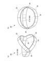
- FIG. 1A and 1B are diagrams schematically showing the electroencephalogram measurement device 1 attached to the subject's head 99
- FIG. is a perspective view.
- the electrode part 10 is removed and shown.
- 2A and 2B are diagrams schematically showing the electroencephalogram measurement apparatus 1, FIG. 2A being a perspective view seen from the front side, and FIG. 2B being a perspective view seen from the rear side.
- 3A and 3B are diagrams schematically showing the frame 20, FIG. 3A being a perspective view seen from the rear side, and FIG. 3B being a perspective view seen from the rear side.
- FIG. 1A and 1B are diagrams schematically showing the electroencephalogram measurement device 1 attached to the subject's head 99
- FIG. is a perspective view.
- the electrode part 10 is removed and shown.
- 2A and 2B are diagrams schematically showing the electroencephalogram measurement apparatus 1, FIG. 2A being a perspective view seen from the front side, and FIG. 2B being a perspective view seen from the rear side.
- FIG. 4 is a perspective view of the electrode section 10.
- FIG. FIG. 5 is a cross-sectional view schematically showing a state in which the electrode section 10 is attached to the electrode fixing member 70 in the electroencephalogram measurement device 1.
- the inner side will be described as the side facing (contacting) the head 99 in the frame 20, and the outer side will be described as the opposite side (the side not facing the head 99).
- the electroencephalogram measurement device 1 is attached to a person's head 99, detects electroencephalograms as potential fluctuations from the living body, and outputs the detected electroencephalograms to an electroencephalogram display device (not shown).
- the electroencephalogram display device acquires electroencephalograms detected by the electroencephalogram measuring device 1, displays them on a monitor, stores data, and performs well-known electroencephalogram analysis processing.
- the electroencephalogram measurement apparatus 1 includes a frame 20, a sheet-like electrode fixing member 70 attached to an opening 25 on the occipital side of the frame 20, and an electrode section 10 attached to the electrode fixing member 70.
- the elastic electrode fixing member 70 extends along the shape of the head 99 (occipital region).
- the electrode section 10 attached to the electrode fixing member 70 is pressed against the head 99 with an appropriate force by the elastic force of the electrode fixing member 70 .
- the frame 20 has a mounting adjustment portion 90 which is provided on the frame 20 and which has an elastic member and which can adjust the contact state of the electrode portion 10 with the head portion 99 .
- a mounting adjustment portion 90 which is provided on the frame 20 and which has an elastic member and which can adjust the contact state of the electrode portion 10 with the head portion 99 .
- the wearing adjustment section 90 a configuration having a top-of-the-head wearing adjustment section 92 that mainly adjusts the wearing state in the head circumference direction will be described. A specific description will be given below.
- the frame 20 is provided along the forehead, temporal region, and occipital region of the head 99 using a frame-shaped (belt-shaped) rigid member, flexible member, elastic member, or a combination thereof.
- hard materials include thermoplastic resins (ABS, PE, PA, PBT, PC, PEEK, PEI, PET, PMMA, POM, PP, PPS, PS) and thermosetting resins (phenol resin, epoxy resin, urea resin, melamine resin), metals (aluminum, copper, stainless steel), etc. can be used.
- Flexible materials include PET film, PE film, PP film, PVC film, PEN film, PI film, vegetable fiber cloth (cotton, morning), animal fiber cloth (silk, wool, alpaca, angora, cashmere, mohair), synthetic fiber Cloth (PE, PA, PC, PES), carbon fiber cloth, aramid fiber cloth, aluminum plate, SUS plate, copper plate, etc. can be used. Silicone rubber, TPS, TPO, TPVC, TPU, TPEE, TPAE, natural rubber, synthetic rubber, chloroprene rubber, urethane rubber, and fluororubber can be used as the elastic member.
- the frame 20 has a front peripheral band member 21 , a rear peripheral frame 22 and a top frame 23 .
- the front peripheral band member 21 and the rear peripheral frame 22 are connected by two connecting portions 29 positioned at the temporal region of the head 99 when worn, and are connected around the head 99 (forehead, temporal region) in the connected state. part, back of the head).
- the top frame 23 extends from the two connecting portions 29 and is curved along the top of the head 99 .
- the front peripheral band member 21 is a stretchable belt-like member provided along the forehead of the forehead, in other words, extending in the head circumference direction (forehead side).
- the front peripheral band member 21 extends according to the head circumference, so that the wearing state in the head circumference direction is properly tightened. It functions as the head circumference mounting adjustment part 91 to be adjusted.
- the material of the front peripheral band member 21 is not particularly limited as long as it can follow the shape of the head circumference and has elasticity. flat rubber).
- the stretchable portion may be a part.
- the rear peripheral frame 22 is made of a hard member such as polyamide resin, and is curved along the shape of the back of the head and provided in a frame shape (belt shape) having a predetermined width.
- the top frame 23 is made of a hard material such as polyamide resin, and is curved along the shape of the temporal region to the top of the head and provided in a frame shape (belt shape) with a predetermined width. .
- Electrode fixing member 70 The posterior peripheral frame 22 and the top frame 23 described above form an opening 25 on the occipital side so as to surround them.
- An electrode fixing member 70 is attached to the top frame 23 and the rear peripheral frame 22 and closes the opening 25 .
- the electrode fixing member 70 is configured with a stretchable sheet material.
- the thickness of the sheet material is not particularly limited, but it is preferable that the thickness be such that it can be stretched sufficiently when attached to the head 99 and has the strength not to break even in continuous use. can do.
- a rubber-like elastic member can be used as the material of the sheet material.
- the material can be the same as the material of the electrode portion 10 to be described later.
- the electrode fixing member 70 may be detachable from the frame 20 (more specifically, the rear peripheral frame 22 and the top frame 23), and the mounting position thereof may be adjustable.
- Various mechanisms such as a hook-and-loop fastener mechanism, a button fitting mechanism, and a screw fitting mechanism can be adopted as the attachment/detachment mechanism.
- the electrode fixing member 70 and the frame 20 may be integrally made of the same material (eg, silicone rubber).
- the portions to be the frame 20 are thick and have a substantially non-stretchable structure, and the portions to be the electrode fixing members 70 are thin and stretchable.
- the electrode fixing member 70 has a plurality of electrode mounting members 75 for mounting the electrode section 10 at predetermined positions (electrode positions based on the 10-20 arrangement method).
- electrode mounting members 75 are provided at four electrode positions P3, P4, O1, and O2 in the 10-20 arrangement method.
- the electrode attachment member 75 has a substantially donut shape with a through hole 76 in the center when viewed from above.
- a male snap button 53 of the electrode section 10 which will be described later, is inserted through the through hole 76 from the inside toward the outside.
- FIG. 4 shows a perspective view of the electrode section 10.
- FIG. 5 shows a sectional view of the state where the electrode section 10 is attached to the electrode mounting member 75 of the electrode fixing member 70.
- FIG. 4 shows a perspective view of the electrode section 10.
- FIG. 5 shows a sectional view of the state where the electrode section 10 is attached to the electrode mounting member 75 of the electrode fixing member 70.
- the electrode section 10 has an electrode section main body 30 and a cap-integrated snap button 50 .
- the cap-integrated snap button 50 is electrically conductive, has a cylindrical shape with a bottom, and functions as a holder that accommodates the electrode unit main body 30 therein, and functions as a connection unit that connects to an external measurement unit.
- the electrode portion main body 30 is fixed inside the tubular shape of the cap-integrated snap button 50 with a silicone adhesive or the like.
- the electrode portion main body 30 has a base portion 31 , a protrusion portion 32 , a conductive contact portion 33 and a signal line portion 34 .
- the base portion 31 and the projection portion 32 are integrally provided by a rubber-like elastic member. A specific material for the elastic member will be described later. Note that the base portion 31 and the projection portion 32 are not limited to being provided integrally, and may be provided separately and assembled with an adhesive or a fitting structure.
- the base 31 has a substantially cylindrical shape.
- a plurality of substantially conical protrusions 32 protruding downward in the drawing are provided at predetermined intervals in the circular circumferential direction on a circular base lower surface 36 on one end side (lower side in the drawing) of the base 31 .
- the shape of the protrusion 32 is not limited to a conical shape, and various shapes such as a pyramid such as a triangular pyramid and a cylindrical shape can be adopted.
- a conductive contact portion 33 is provided on at least the tip side surface of the protruding portion 32 .
- a conductive contact portion 33 may be provided over the entire surface of the protrusion 32 .
- the outer diameter of the base 31 is, for example, 10 mm to 50 mm.
- the height (thickness) of the base 31 is, for example, 2 mm to 30 mm.
- the height of the protrusion 32 is, for example, 3 mm to 15 mm.
- the width of the protrusion 32 (the outer diameter of the root portion) is, for example, 1 mm to 10 mm.
- the electrode portion body 30 is provided with a signal line portion 34 as a signal path connected to the conductive contact portion 33 .
- Various wiring structures can be employed for the signal line portion 34 as long as they are in a manner that conducts through the base portion 31 and the projection portion 32 .
- the signal line portion 34 is provided so as to pass from the conductive contact portion 33 at the tip of the protrusion 32 through the inside of the protrusion 32 and the base portion 31 and be exposed on the base upper surface 35 of the base portion 31 .
- the tip of the signal line portion 34 has a protruded structure, a structure that is substantially on the same plane, or a structure that is buried with respect to the tip portion of the protrusion 32 or its vicinity, that is, the region where the conductive contact portion 33 is formed.
- a projecting structure may be used.
- a projecting portion at the tip of the signal line portion 34 is partially or entirely covered with the conductive contact portion 33 .
- the protruding structure of the tip of the signal line portion 34 may be unfolded, folded, or wrapped around the surface of the tip of the projection 32 .
- a structure provided on the surfaces of the projection portion 32 and the base portion 31 may be used, or a wiring structure may be used in which a portion is provided inside and a portion is provided on the surface.
- the electrode portion main body 30 (the base portion 31 and the projection portion 32) and the electrode fixing member 70 can be made of a rubber-like elastic body as described above.
- the rubber-like elastic body is rubber or a thermoplastic elastomer (also simply referred to as “elastomer (TPE)”). Examples of rubber include silicone rubber.
- thermoplastic elastomers examples include styrene-based TPE (TPS), olefin-based TPE (TPO), vinyl chloride-based TPE (TPVC), urethane-based TPE (TPU), ester-based TPE (TPEE), and amide-based TPE (TPAE).
- TPS styrene-based TPE
- TPO olefin-based TPE
- TPVC vinyl chloride-based TPE
- TPU urethane-based TPE
- TPEE ester-based TPE
- TPAE amide-based TPE
- the type A durometer hardness of the surface of the electrode body 30 measured in accordance with JIS K 6253 (1997) at 37° C.
- the hardness is A
- the rubber hardness A is, for example, 15 or more and 55 or less.
- the silicone rubber-based curable composition will be described.
- the silicone rubber can be composed of a cured product of a silicone rubber-based curable composition.
- the curing step of the silicone rubber-based curable resin composition is, for example, heating at 100 to 250° C. for 1 to 30 minutes (primary curing), followed by post-baking (secondary curing) at 100 to 200° C. for 1 to 4 hours. It is done by
- An insulating silicone rubber is a silicone rubber that does not contain a conductive filler
- a conductive silicone rubber is a silicone rubber that contains a conductive filler
- the silicone rubber-based curable composition according to this embodiment can contain a vinyl group-containing organopolysiloxane (A).
- the vinyl group-containing organopolysiloxane (A) is a polymer that is the main component of the silicone rubber-based curable composition of the present embodiment.
- the insulating silicone rubber-based curable composition and the conductive silicone rubber-based curable composition may contain the same vinyl group-containing linear organopolysiloxane.
- the vinyl group-containing linear organopolysiloxane of the same kind includes at least the same vinyl group with the same functional group and has a linear shape. can be different.
- the insulating silicone rubber-based curable composition and the conductive silicone rubber-based curable composition may further contain different vinyl group-containing organopolysiloxanes.
- the vinyl group-containing organopolysiloxane (A) can contain a vinyl group-containing linear organopolysiloxane (A1) having a linear structure.
- the vinyl group-containing linear organopolysiloxane (A1) has a linear structure and contains vinyl groups, and the vinyl groups serve as cross-linking points during curing.
- the vinyl group content of the vinyl group-containing linear organopolysiloxane (A1) is not particularly limited, but for example, it preferably has two or more vinyl groups in the molecule and is 15 mol % or less. , 0.01 to 12 mol %.
- the amount of vinyl groups in the vinyl group-containing linear organopolysiloxane (A1) is optimized, and a network can be reliably formed with each component described later.
- "-" means including both numerical values.
- the vinyl group content is the mol % of the vinyl group-containing siloxane units when the total units constituting the vinyl group-containing linear organopolysiloxane (A1) are taken as 100 mol %. .
- one vinyl group is considered to be one vinyl group-containing siloxane unit.
- the degree of polymerization of the vinyl group-containing linear organopolysiloxane (A1) is not particularly limited, it is, for example, preferably in the range of about 1,000 to 10,000, more preferably in the range of about 2,000 to 5,000.
- the degree of polymerization can be determined, for example, as a polystyrene-equivalent number-average polymerization degree (or number-average molecular weight) in GPC (gel permeation chromatography) using chloroform as a developing solvent.
- the specific gravity of the vinyl group-containing linear organopolysiloxane (A1) is not particularly limited, but is preferably in the range of about 0.9 to 1.1.
- the heat resistance, flame retardancy, chemical stability, etc. of the resulting silicone rubber can be improved by using those having the degree of polymerization and specific gravity within the ranges described above. can be improved.
- vinyl group-containing linear organopolysiloxane (A1) those having a structure represented by the following formula (1) are particularly preferable.
- R 1 is a substituted or unsubstituted alkyl group, alkenyl group, aryl group, or a hydrocarbon group of a combination thereof having 1 to 10 carbon atoms.
- the alkyl group having 1 to 10 carbon atoms includes, for example, methyl group, ethyl group, propyl group, etc. Among them, methyl group is preferable.
- the alkenyl group having 1 to 10 carbon atoms includes, for example, vinyl group, allyl group, butenyl group, etc. Among them, vinyl group is preferred.
- the aryl group having 1 to 10 carbon atoms includes, for example, a phenyl group.
- R 2 is a substituted or unsubstituted alkyl group, alkenyl group, aryl group having 1 to 10 carbon atoms, or a hydrocarbon group combining these.
- the alkyl group having 1 to 10 carbon atoms includes, for example, methyl group, ethyl group, propyl group, etc. Among them, methyl group is preferable.
- alkenyl groups having 1 to 10 carbon atoms include vinyl groups, allyl groups and butenyl groups.
- the aryl group having 1 to 10 carbon atoms include a phenyl group.
- R 3 is a substituted or unsubstituted alkyl group having 1 to 8 carbon atoms, an aryl group, or a hydrocarbon group combining these.
- the alkyl group having 1 to 8 carbon atoms includes, for example, methyl group, ethyl group, propyl group, etc. Among them, methyl group is preferable.
- Examples of the aryl group having 1 to 8 carbon atoms include a phenyl group.
- examples of substituents for R 1 and R 2 in formula (1) include methyl group and vinyl group, and examples of substituents for R 3 include methyl group.
- a plurality of R 1 are independent of each other and may be different from each other or may be the same. Furthermore, the same applies to R 2 and R 3 .
- m and n are the numbers of repeating units constituting the vinyl group-containing linear organopolysiloxane (A1) represented by formula (1), m is an integer of 0 to 2000, and n is 1000 to 10000. is an integer of m is preferably 0-1000 and n is preferably 2000-5000.
- vinyl group-containing linear organopolysiloxane (A1) represented by formula (1) include, for example, those represented by the following formula (1-1).
- R 1 and R 2 are each independently a methyl group or a vinyl group, and at least one is a vinyl group.
- the vinyl group-containing linear organopolysiloxane (A1) a first vinyl group-containing vinyl group having a vinyl group content of 2 or more vinyl groups in the molecule and not more than 0.4 mol% It contains a linear organopolysiloxane (A1-1) and a second vinyl group-containing linear organopolysiloxane (A1-2) having a vinyl group content of 0.5 to 15 mol%. It is preferable to have As crude rubber, which is a raw material of silicone rubber, a first vinyl group-containing linear organopolysiloxane (A1-1) having a general vinyl group content and a second vinyl group-containing linear organopolysiloxane having a high vinyl group content were used.
- the vinyl groups can be unevenly distributed, and the crosslink density can be more effectively formed in the crosslink network of the silicone rubber. As a result, the tear strength of silicone rubber can be increased more effectively.
- the vinyl group-containing linear organopolysiloxane (A1) for example, a unit in which R 1 is a vinyl group and/or a unit in which R 2 is a vinyl group in the above formula (1-1) , a first vinyl group-containing linear organopolysiloxane (A1-1) having two or more in the molecule and containing 0.4 mol% or less, and a unit in which R 1 is a vinyl group and / or R It is preferable to use a second vinyl group-containing linear organopolysiloxane (A1-2) containing 0.5 to 15 mol % of units in which 2 is a vinyl group.
- the first vinyl group-containing linear organopolysiloxane (A1-1) preferably has a vinyl group content of 0.01 to 0.2 mol %.
- the second vinyl group-containing linear organopolysiloxane (A1-2) preferably has a vinyl group content of 0.8 to 12 mol %.
- (A1-1) and (A1-2) are not particularly limited, but for example, the weight ratio of (A1-1):(A1-2) is preferably 50:50 to 95:5, and 80:20 to 90: 10 is more preferred.
- the first and second vinyl group-containing linear organopolysiloxanes (A1-1) and (A1-2) may be used singly or in combination of two or more. good.
- the vinyl group-containing organopolysiloxane (A) may contain a vinyl group-containing branched organopolysiloxane (A2) having a branched structure.
- the silicone rubber-based curable composition of the present embodiment may contain a cross-linking agent.
- Cross-linking agents can include organohydrogenpolysiloxanes (B).
- Organohydrogenpolysiloxane (B) is classified into linear organohydrogenpolysiloxane (B1) having a linear structure and branched organohydrogenpolysiloxane (B2) having a branched structure. Either or both may be included.
- the insulating silicone rubber-based curable composition and the conductive silicone rubber-based curable composition may contain the same type of cross-linking agent.
- the same type of cross-linking agent should have at least a common structure such as a linear structure or a branched structure, and may contain different molecular weight distributions and different functional groups in the molecule, and the amount added may be different.
- the insulating silicone rubber-based curable composition and the conductive silicone rubber-based curable composition may further contain different cross-linking agents.
- the linear organohydrogenpolysiloxane (B1) has a linear structure and a structure ( ⁇ Si—H) in which hydrogen is directly bonded to Si, and is the vinyl group-containing organopolysiloxane (A). It is a polymer that undergoes a hydrosilylation reaction with vinyl groups other than vinyl groups contained in other components of the silicone rubber-based curable composition, thereby cross-linking these components.
- the molecular weight of the linear organohydrogenpolysiloxane (B1) is not particularly limited, for example, the weight average molecular weight is preferably 20,000 or less, more preferably 1,000 or more and 10,000 or less.
- the weight average molecular weight of the linear organohydrogenpolysiloxane (B1) can be measured, for example, by polystyrene conversion in GPC (gel permeation chromatography) using chloroform as a developing solvent.
- the linear organohydrogenpolysiloxane (B1) does not have a vinyl group. Thereby, it is possible to accurately prevent the progress of the cross-linking reaction in the molecule of the linear organohydrogenpolysiloxane (B1).
- linear organohydrogenpolysiloxane (B1) for example, one having a structure represented by the following formula (2) is preferably used.
- R 4 is a substituted or unsubstituted alkyl group, alkenyl group, aryl group having 1 to 10 carbon atoms, a hydrocarbon group combining these groups, or a hydride group.
- the alkyl group having 1 to 10 carbon atoms includes, for example, methyl group, ethyl group, propyl group, etc. Among them, methyl group is preferable.
- alkenyl groups having 1 to 10 carbon atoms include vinyl groups, allyl groups and butenyl groups.
- the aryl group having 1 to 10 carbon atoms include a phenyl group.
- R 5 is a substituted or unsubstituted alkyl group, alkenyl group, aryl group having 1 to 10 carbon atoms, a hydrocarbon group combining these, or a hydride group.
- alkyl group having 1 to 10 carbon atoms include methyl group, ethyl group and propyl group, with methyl group being preferred.
- alkenyl groups having 1 to 10 carbon atoms include vinyl groups, allyl groups and butenyl groups.
- Examples of the aryl group having 1 to 10 carbon atoms include a phenyl group.
- a plurality of R 4 are independent of each other and may be different from each other or may be the same. The same is true for R5 . However, at least two or more of the plurality of R 4 and R 5 are hydride groups.
- R 6 is a substituted or unsubstituted alkyl group having 1 to 8 carbon atoms, an aryl group, or a hydrocarbon group combining these.
- the alkyl group having 1 to 8 carbon atoms includes, for example, methyl group, ethyl group, propyl group, etc. Among them, methyl group is preferable.
- Examples of the aryl group having 1 to 8 carbon atoms include a phenyl group.
- a plurality of R 6 are independent from each other and may be different from each other or may be the same.
- substituents for R 4 , R 5 and R 6 in formula (2) include methyl group and vinyl group, with methyl group being preferred from the viewpoint of preventing intramolecular cross-linking reaction.
- m and n are the numbers of repeating units constituting the linear organohydrogenpolysiloxane (B1) represented by formula (2), m is an integer of 2 to 150, and n is an integer of 2 to 150. is.
- m is an integer from 2-100 and n is an integer from 2-100.
- the straight-chain organohydrogenpolysiloxane (B1) may be used alone or in combination of two or more.
- the branched organohydrogenpolysiloxane (B2) has a branched structure, it is a component that forms regions with a high crosslink density and greatly contributes to the formation of a loose and dense structure of crosslink density in the silicone rubber system. Further, like the linear organohydrogenpolysiloxane (B1), it has a structure ( ⁇ Si—H) in which hydrogen is directly bonded to Si, and in addition to the vinyl group of the vinyl group-containing organopolysiloxane (A), silicone It is a polymer that undergoes a hydrosilylation reaction with the vinyl groups of the components blended in the rubber-based curable composition to crosslink these components.
- the specific gravity of the branched organohydrogenpolysiloxane (B2) is in the range of 0.9 to 0.95.
- the branched organohydrogenpolysiloxane (B2) does not have a vinyl group. Thereby, it is possible to accurately prevent the progress of the cross-linking reaction in the molecule of the branched organohydrogenpolysiloxane (B2).
- branched organohydrogenpolysiloxane (B2) one represented by the following average compositional formula (c) is preferable.
- R 7 is a monovalent organic group, a is an integer ranging from 1 to 3, m is the number of H a (R 7 ) 3-a SiO 1/2 units, n is SiO 4/ is a number of 2 units)
- R 7 is a monovalent organic group, preferably a substituted or unsubstituted alkyl group having 1 to 10 carbon atoms, an aryl group, or a hydrocarbon group combining these.
- the alkyl group having 1 to 10 carbon atoms includes, for example, methyl group, ethyl group, propyl group, etc. Among them, methyl group is preferable.
- Examples of the aryl group having 1 to 10 carbon atoms include a phenyl group.
- a is the number of hydride groups (hydrogen atoms directly bonded to Si) and is an integer in the range of 1 to 3, preferably 1.
- m is the number of H a (R 7 ) 3-a SiO 1/2 units
- n is the number of SiO 4/2 units.
- the branched organohydrogenpolysiloxane (B2) has a branched structure.
- the linear organohydrogenpolysiloxane (B1) and the branched organohydrogenpolysiloxane (B2) differ in that their structures are linear or branched.
- the number of bound alkyl groups R (R/Si) is 1.8 to 2.1 for the linear organohydrogenpolysiloxane (B1) and 0.8 to 1 for the branched organohydrogenpolysiloxane (B2). .7 range.
- the branched organohydrogenpolysiloxane (B2) has a branched structure, for example, when heated to 1000° C. at a heating rate of 10° C./min in a nitrogen atmosphere, the residual amount is 5% or more. becomes.
- the straight-chain organohydrogenpolysiloxane (B1) is straight-chain, the amount of residue after heating under the above conditions is almost zero.
- branched organohydrogenpolysiloxane (B2) include those having a structure represented by the following formula (3).
- R 7 is a substituted or unsubstituted alkyl group having 1 to 8 carbon atoms, an aryl group, a hydrocarbon group combining these, or a hydrogen atom.
- the alkyl group having 1 to 8 carbon atoms includes, for example, methyl group, ethyl group, propyl group, etc. Among them, methyl group is preferred.
- Examples of the aryl group having 1 to 8 carbon atoms include a phenyl group.
- the substituent of R7 include a methyl group and the like.
- a plurality of R 7 are independent of each other and may be different from each other or may be the same.
- the branched organohydrogenpolysiloxane (B2) may be used alone or in combination of two or more.
- the amount of hydrogen atoms (hydride groups) directly bonded to Si is not particularly limited.
- linear organohydrogenpolysiloxane (B1) and branched organohydrogenpolysiloxane are The total amount of hydride groups in the siloxane (B2) is preferably from 0.5 to 5 mol, more preferably from 1 to 3.5 mol.
- the silicone rubber-based curable composition according to this embodiment contains a non-conductive filler.
- the non-conductive filler may contain silica particles (C) as needed. Thereby, the hardness and mechanical strength of the elastomer can be improved.
- the insulating silicone rubber-based curable composition and the conductive silicone rubber-based curable composition may contain the same type of non-conductive filler.
- Non-conductive fillers of the same type may have at least common constituent materials, and may differ in particle size, specific surface area, surface treatment agent, or addition amount thereof.
- the insulating silicone rubber-based curable composition and the conductive silicone rubber-based curable composition may further contain different silane coupling agents.
- the silica particles (C) are not particularly limited, but for example, fumed silica, calcined silica, precipitated silica, etc. are used. These may be used alone or in combination of two or more.
- the silica particles (C) preferably have a BET specific surface area of, for example, 50 to 400 m 2 /g, more preferably 100 to 400 m 2 /g. Also, the average primary particle size of the silica particles (C) is preferably, for example, 1 to 100 nm, more preferably about 5 to 20 nm.
- silica particles (C) having a specific surface area and an average particle size within the above ranges, the hardness and mechanical strength of the formed silicone rubber can be improved, especially the tensile strength can be improved.
- the silicone rubber-based curable composition of the present embodiment can contain a silane coupling agent (D).
- Silane coupling agent (D) can have a hydrolyzable group. The hydrolyzable group is hydrolyzed with water to form a hydroxyl group, and the hydroxyl group undergoes a dehydration condensation reaction with the hydroxyl group on the surface of the silica particle (C), thereby modifying the surface of the silica particle (C).
- the insulating silicone rubber-based curable composition and the conductive silicone rubber-based curable composition may contain the same type of silane coupling agent.
- the silane coupling agents of the same kind should have at least a common functional group, and may differ in other functional groups in the molecule and in the amount added.
- the insulating silicone rubber-based curable composition and the conductive silicone rubber-based curable composition may further contain different silane coupling agents.
- this silane coupling agent (D) can contain a silane coupling agent having a hydrophobic group.
- the hydrophobic group is imparted to the surface of the silica particles (C), so that the cohesive force of the silica particles (C) in the silicone rubber-based curable composition and further in the silicone rubber is reduced (hydrogen aggregation due to bonding is reduced), and as a result, it is assumed that the dispersibility of the silica particles (C) in the silicone rubber-based curable composition is improved. This increases the interface between the silica particles (C) and the rubber matrix, increasing the reinforcing effect of the silica particles (C).
- the slipperiness of the silica particles (C) within the matrix is improved when the rubber matrix is deformed.
- the improved dispersibility and slipperiness of the silica particles (C) improve the mechanical strength (for example, tensile strength and tear strength) of the silicone rubber due to the silica particles (C).
- the silane coupling agent (D) can contain a silane coupling agent having a vinyl group.
- vinyl groups are introduced onto the surfaces of the silica particles (C). Therefore, during curing of the silicone rubber-based curable composition, that is, a hydrosilylation reaction occurs between the vinyl group of the vinyl group-containing organopolysiloxane (A) and the hydride group of the organohydrogenpolysiloxane (B). , When a network (crosslinked structure) is formed by these, the vinyl groups possessed by the silica particles (C) also participate in the hydrosilylation reaction with the hydride groups possessed by the organohydrogenpolysiloxane (B). Silica particles (C) also come to be taken in. As a result, it is possible to reduce the hardness and increase the modulus of the formed silicone rubber.
- silane coupling agent (D) a silane coupling agent having a hydrophobic group and a silane coupling agent having a vinyl group can be used in combination.
- silane coupling agent (D) examples include those represented by the following formula (4).
- n represents an integer of 1-3.
- Y represents a functional group having a hydrophobic group, a hydrophilic group or a vinyl group, and when n is 1 it is a hydrophobic group, and when n is 2 or 3 at least one of It is a hydrophobic group.
- X represents a hydrolyzable group.
- the hydrophobic group is an alkyl group having 1 to 6 carbon atoms, an aryl group, or a hydrocarbon group having a combination thereof, and examples thereof include a methyl group, an ethyl group, a propyl group, a phenyl group, and the like. Methyl groups are preferred.
- the hydrophilic group includes, for example, a hydroxyl group, a sulfonic acid group, a carboxyl group, a carbonyl group, etc. Among them, a hydroxyl group is particularly preferable.
- the hydrophilic group may be contained as a functional group, but is preferably not contained from the viewpoint of imparting hydrophobicity to the silane coupling agent (D).
- the hydrolyzable group includes an alkoxy group such as a methoxy group and an ethoxy group, a chloro group, a silazane group, and the like.
- a silazane group is preferable because of its high reactivity with the silica particles (C).
- a compound having a silazane group as a hydrolyzable group has two structures of (Y n —Si—) in the above formula (4) due to its structural characteristics.
- silane coupling agent (D) represented by the above formula (4) are as follows.
- Those having a hydrophobic group as the functional group include, for example, methyltrimethoxysilane, dimethyldimethoxysilane, phenyltrimethoxysilane, methyltriethoxysilane, dimethyldiethoxysilane, phenyltriethoxysilane, n-propyltrimethoxysilane, alkoxysilanes such as n-propyltriethoxysilane, hexyltrimethoxysilane, hexyltriethoxysilane, decyltrimethoxysilane; chlorosilanes such as methyltrichlorosilane, dimethyldichlorosilane, trimethylchlorosilane, phenyltrichlorosilane; hexamethyldisilazane.
- silane coupling agent having a trimethylsilyl group containing at least one selected from the group consisting of hexamethyldisilazane, trimethylchlorosilane, trimethylmethoxysilane, and trimethylethoxysilane is preferred.
- Examples of those having a vinyl group as the functional group include methacryloxypropyltriethoxysilane, methacryloxypropyltrimethoxysilane, methacryloxypropylmethyldiethoxysilane, methacryloxypropylmethyldimethoxysilane, vinyltriethoxysilane, and vinyltrimethoxysilane.
- alkoxysilanes such as silane and vinylmethyldimethoxysilane
- chlorosilanes such as vinyltrichlorosilane and vinylmethyldichlorosilane
- divinyltetramethyldisilazane divinyltetramethyldisilazane.
- a silane coupling agent having a vinyl group-containing organosilyl group containing one or more selected from the group consisting of methyldimethoxysilane is preferred.
- silane coupling agent (D) contains two kinds of a silane coupling agent having a trimethylsilyl group and a silane coupling agent having a vinyl group-containing organosilyl group
- those having a hydrophobic group include hexamethyldisilazane, Divinyltetramethyldisilazane is preferably included as one having a vinyl group.
- the ratio of (D1) and (D2) is not particularly limited, but for example, (D1):(D2) in a weight ratio of 1:0.001 to 1:0.35, preferably 1:0.01 to 1:0.20, more preferably 1:0.03 to 1:0 .15. Desired physical properties of the silicone rubber can be obtained by setting it to such a numerical range. Specifically, the dispersibility of silica in the rubber and the crosslinkability of the rubber can be balanced.
- the lower limit of the content of the silane coupling agent (D) is preferably 1% by mass or more with respect to 100 parts by weight of the total amount of the vinyl group-containing organopolysiloxane (A). It is more preferably at least 5% by mass, even more preferably at least 5% by mass.
- the upper limit of the content of the silane coupling agent (D) is preferably 100% by mass or less, and 80% by mass or less with respect to 100 parts by weight of the total amount of the vinyl group-containing organopolysiloxane (A). It is more preferable that the content is 40% by mass or less.
- the silicone rubber can have appropriate mechanical properties.
- the silicone rubber-based curable composition according to this embodiment may contain a catalyst.
- the catalyst may contain platinum or a platinum compound (E).
- Platinum or a platinum compound (E) is a catalytic component that acts as a catalyst during curing.
- the amount of platinum or platinum compound (E) added is a catalytic amount.
- the insulating silicone rubber-based curable composition and the conductive silicone rubber-based curable composition may contain the same type of catalyst. Catalysts of the same kind may have at least common constituent materials, and the catalysts may contain different compositions and may differ in addition amount.
- the insulating silicone rubber-based curable composition and the conductive silicone rubber-based curable composition may further contain different catalysts.
- platinum or platinum compound (E) a known one can be used, for example, platinum black, platinum supported on silica or carbon black, chloroplatinic acid or an alcohol solution of chloroplatinic acid, A complex salt of platinic acid and olefin, a complex salt of chloroplatinic acid and vinyl siloxane, and the like are included.
- the platinum or platinum compound (E) may be used alone or in combination of two or more.
- the content of platinum or platinum compound (E) in the silicone rubber-based curable composition means the amount of catalyst, and can be set as appropriate.
- (A), silica particles (C), the total amount of 100 parts by weight of the silane coupling agent (D), platinum group metal is an amount of 0.01 to 1000 ppm by weight unit, preferably 0. The amount is 1 to 500 ppm.
- the silicone rubber-based curable composition according to the present embodiment may contain water (F) in addition to the above components (A) to (E).
- Water (F) is a component that functions as a dispersion medium for dispersing each component contained in the silicone rubber-based curable composition and contributes to the reaction between the silica particles (C) and the silane coupling agent (D). . Therefore, the silica particles (C) and the silane coupling agent (D) can be linked to each other more reliably in the silicone rubber, and uniform properties can be exhibited as a whole.
- the silicone rubber-based curable composition of the present embodiment may further contain other components in addition to the above components (A) to (F).
- Other components include silica particles (C) such as diatomaceous earth, iron oxide, zinc oxide, titanium oxide, barium oxide, magnesium oxide, cerium oxide, calcium carbonate, magnesium carbonate, zinc carbonate, glass wool, and mica.
- additives such as inorganic fillers, reaction inhibitors, dispersants, pigments, dyes, antistatic agents, antioxidants, flame retardants, and thermal conductivity improvers.
- the conductive solution (conductive silicone rubber composition) according to the present embodiment contains the conductive filler and solvent in addition to the silicone rubber-based curable composition containing no conductive filler.
- solvents can be used as the solvent, and for example, a high boiling point solvent can be included. These may be used alone or in combination of two or more.
- solvents examples include aliphatic hydrocarbons such as pentane, hexane, cyclohexane, heptane, methylcyclohexane, ethylcyclohexane, octane, decane, dodecane, and tetradecane; benzene, toluene, ethylbenzene, xylene, trifluoromethylbenzene; , aromatic hydrocarbons such as benzotrifluoride; diethyl ether, diisopropyl ether, dibutyl ether, cyclopentyl methyl ether, cyclopentyl ethyl ether, ethylene glycol dimethyl ether, ethylene glycol diethyl ether, diethylene glycol dimethyl ether, 1,4-dioxane, 1,3 - ethers such as dioxane and tetrahydrofuran; haloalkanes such as
- the conductive solution can have a viscosity suitable for various coating methods such as spray coating and dip coating.
- the lower limit of the content of the silica particles (C) contained in the electrode portion main body 30 is the silica particles (C) and the conductive filler
- the upper limit of the content of the silica particles (C) contained in the electrode portion main body 30 is, for example, 20% by mass or less with respect to 100% by mass of the total amount of the silica particles (C) and the conductive filler. , preferably 15% by mass or less, more preferably 10% by mass or less.
- a conductive silicone rubber can be obtained by heating and drying the conductive solution as necessary.
- the conductive silicone rubber may be configured without silicone oil. As a result, it is possible to prevent the silicone oil from bleeding out on the surface of the electrode portion main body 30 to reduce the conductivity.
- the signal line portion 34 can use a known one, and can be made of conductive fiber, for example.
- conductive fiber one or more selected from the group consisting of metal fiber, metal-coated fiber, carbon fiber, conductive polymer fiber, conductive polymer-coated fiber, and conductive paste-coated fiber can be used. These may be used alone or in combination of two or more.
- the metal material of the metal fibers and metal-coated fibers is not limited as long as it has conductivity, but copper, silver, gold, nickel, tin, lead, zinc, bismuth, antimony, stainless steel, aluminum, silver/chloride silver and alloys thereof; These may be used alone or in combination of two or more. Among these, silver can be used from the viewpoint of conductivity. Moreover, it is preferable that the metal material does not contain a metal such as chromium that causes a load on the environment.
- the fiber materials of the metal-coated fibers, conductive polymer-coated fibers, and conductive paste-coated fibers are not particularly limited, but may be synthetic fibers, semi-synthetic fibers, or natural fibers. Among these, it is preferable to use polyester, nylon, polyurethane, silk, cotton, and the like. These may be used alone or in combination of two or more.
- Examples of the carbon fibers include PAN-based carbon fibers and pitch-based carbon fibers.
- the conductive polymer material of the conductive polymer fiber and the conductive polymer-coated fiber is, for example, a mixture of a conductive polymer such as polythiophene, polypyrrole, polyaniline, polyacetylene, polyphenylene vinylene, polynaphthalene, and derivatives thereof and a binder resin, Alternatively, an aqueous solution of a conductive polymer such as PEDOT-PSS ((3,4-ethylenedioxythiophene)-poly(styrenesulfonic acid)) is used.
- PEDOT-PSS ((3,4-ethylenedioxythiophene)-poly(styrenesulfonic acid)
- the resin material contained in the conductive paste of the conductive paste-coated fiber is not particularly limited, but preferably has elasticity. It can contain one or more selected from the group consisting of propylene rubbers. These may be used alone or in combination of two or more.
- the conductive filler contained in the conductive paste of the conductive paste-coated fiber is not particularly limited, and known conductive materials may be used, such as metal particles, metal fibers, metal-coated fibers, carbon black, acetylene black, graphite, carbon It may contain one or more selected from the group consisting of fibers, carbon nanotubes, conductive polymers, conductive polymer-coated fibers and metal nanowires.
- the metal constituting the conductive filler is not particularly limited, but for example, copper, silver, gold, nickel, tin, lead, zinc, bismuth, antimony, silver/silver chloride, or at least one of these alloys. or, alternatively, two or more of these.
- silver or copper is preferable because of its high conductivity and high availability.
- the signal line portion 34 may be composed of twisted yarn obtained by twisting a plurality of linear conductive fibers. As a result, breakage of the signal line portion 34 during deformation can be suppressed.
- the coating of the conductive fiber means not only covering the outer surface of the fiber material, but also, in the case of a twisted yarn obtained by twisting single fibers, a metal or a conductive polymer is added between the fibers in the twisted yarn. , or impregnated with a conductive paste to cover each single fiber constituting the twisted yarn.
- the tensile elongation at break of the signal wire portion 34 is, for example, 1% to 50%, preferably 1.5% to 45%. By setting the value within such a numerical range, it is possible to suppress excessive deformation of the protrusion 32 while suppressing breakage during deformation.
- the conductive member of the conductive contact portion 33 is, for example, a paste containing a highly conductive metal (so-called conductive paste).
- the highly conductive metal includes one or more selected from the group consisting of copper, silver, gold, nickel, tin, lead, zinc, bismuth, antimony, or alloys thereof.
- silver, silver chloride, and copper are suitable from the viewpoint of availability and conductivity.
- the top of the protrusion 32 made of a rubber-like elastic body is dipped (immersed) in a paste-like conductive solution containing a highly conductive metal. Apply). Thereby, a conductive contact portion 33 is formed on the surface of the projection portion 32 .
- the conductive contact portion 33 may be formed as a conductive resin layer by applying a conductive solution containing a conductive filler and a solvent to the projection portion 32 . At this time, by using the same type of material (silicone rubber) as the solvent for the protrusion 32, the adhesion of the conductive contact portion 33 (conductive resin layer) can be enhanced.
- a conductive silicone rubber can be obtained by heating and drying the conductive solution as necessary.
- the conductive silicone rubber may be configured without silicone oil. As a result, it is possible to suppress a decrease in conductivity due to bleeding out of the silicone oil onto the surface of the conductive contact portion 33 .
- the cap-integrated snap button 50 is made of, for example, a good conductor metal, has a cylindrical shape with a bottom, and has connecting means (male snap button 53) on the outer surface of the bottomed portion for connection to an external measuring unit.
- metals that are good conductors include stainless steel, copper alloys, aluminum alloys, and brass.
- the cap-integrated snap button 50 integrally includes a cap top plate 51 which is a bottom surface of a bottomed cylindrical shape, and a cylindrical cap body portion 52 extending downward in the figure from the peripheral edge of the cap top plate 51 . .
- a cylindrical male snap button 53 extending upward in the drawing is provided at the center of the outer surface 56 of the circular cap top plate 51 (that is, the center of the circular shape when viewed from above).
- the base upper surface 35 of the electrode unit main body 30 is attached to the inner surface 54 of the cap top plate 51 via a conductive paste layer so as to be in contact therewith.
- the inner surface 54 of the cap top plate 51 and the upper surface 35 of the base portion are arranged so that the upper end portion of the signal line portion 34 is sandwiched therebetween, as described above.
- the male snap button 53 is an interface to which a signal line is attached for connection with an external measurement unit.
- the male snap button 53 has, for example, a shape of a connection terminal in which the diameter of the cylindrical tip side is larger than that of the base side.
- the male snap button 53 is inserted through the through hole 76 from the inside of the electrode fixing member 70 (electrode attaching member 75), and is a portion with an enlarged diameter projecting outward from the through hole 76.
- the male snap button 53 is a female snap button provided on the signal line. It fits with the snap button 49 .
- the electrode mounting member 75 is sandwiched between the female snap button 49 and the cap top plate 51, and the electrode section 10 is fixed to the electrode fixing member 70 with the projecting section 32 facing inward (head 99 side).
- the front peripheral band member 21 of the frame 20 is stretchable, so that the frame 20 can be easily attached to the head circumference.
- the electrode fixing member 70 to which the electrode sections 10 are attached is provided so as to cover the back of the head, when the electroencephalogram measurement device 1 is worn, all the electrode sections 10 are brought into contact with the head 99 with an appropriate force. can be made That is, it is possible to shorten the time required to bring the electrode section 10 into contact with the head 99 appropriately.
- FIG. 6 shows electroencephalogram measurement apparatuses 1A and 1B having electrode fixing members 70A and 70B of modifications.
- the electrode fixing member 70A is configured with an elastic band member. Specifically, it is provided so as to extend in the horizontal direction (that is, from one temporal side to the other temporal side) in the opening 25 on the occipital side formed by the posterior peripheral frame 22 and the top frame 23 . and a plurality of band members (upper and lower band members 79) provided so as to extend in the vertical direction (direction from the back of the head to the top of the head). are intersected in a grid. This can improve breathability.
- All or part of the horizontal band member 78 and the upper and lower band members 79 may be removable and replaceable with respect to the rear peripheral frame 22 and the top frame 23 .
- the electroencephalogram measurement device 1 may be used with parts of the horizontal band member 78 and the upper and lower band members 79 removed.
- the electrode fixing member 70B is provided with a plurality of through holes 71 in the stretchable sheet member.
- the size of the through-holes 71 is not particularly limited, and all of them may have the same size or may have different sizes.
- FIG. 7 shows a modified front peripheral band member 21A.
- the front peripheral band member 21A has a two-stage fixing mechanism using an elastic member and a hook-and-loop fastener as a structure that functions as a head circumference attachment adjustment portion 91 that adjusts the attachment state in the head circumference direction.
- the fixing mechanism of the first stage is as follows. That is, as shown in FIG. 7(a), the front peripheral band member 21A (head circumference attachment adjustment portion 91) is provided with a stretchable band member extending in the head circumference direction so as to be separable to the left and right. Specifically, the front peripheral band member 21A has a first belt-shaped member 211 (right side in the figure) and a second belt-shaped member 212 (left side in the figure) that are divided in the head circumference direction. The first belt-shaped member 211 and the second belt-shaped member 212 are provided so as to be joined together so that the length in the extending direction can be adjusted.
- a hook-and-loop fastener (hook surface) 213 is provided outwardly at the tip portion (end portion on the left side in the figure) of the first belt-shaped member 211 .
- a hook-and-loop fastener (loop surface) 214 is provided facing inward at the tip portion (end portion on the right side in the drawing) of the second belt-shaped member 212 .
- a hook-and-loop fastener (hook surface) 213 and a hook-and-loop fastener (loop surface) 214 are bonded together.
- auxiliary adjusting section 230 that acts to contract the elastic member of the head circumference attachment adjusting section 91 .
- the first belt-shaped member 211 As a mechanism for adjusting the stretched state of the first belt-shaped member 211, it has an elastic belt-shaped first auxiliary belt-shaped member 217, one end of which is fixed to the mounting portion 221. The other end of the first auxiliary belt-shaped member 217 extends toward the tip of the first belt-shaped member 211 (left side in the drawing).
- a first auxiliary hook surface fastener (hook surface) 215 is provided facing outward in a region on the right side of the hook surface fastener (hook surface) 213 of the first belt-shaped member 211 .
- a first auxiliary surface fastener (loop surface) 219 is provided facing inward as a member to be adhered to the first auxiliary surface fastener (hook surface) 215. .
- FIG. 7(c) by adjusting the bonding position of the first auxiliary surface fastener (loop surface) 219 with respect to the first auxiliary surface fastener (hook surface) 215, the extension of the first auxiliary strip member 217 is achieved. You can adjust the state.
- the second belt-shaped member 212 As a mechanism for adjusting the stretched state of the second belt-shaped member 212, it has an elastic belt-shaped second auxiliary belt-shaped member 218 whose one end is fixed to the mounting portion 222. The other end of the second auxiliary belt-shaped member 218 extends toward the tip of the second belt-shaped member 212 (on the right side in the drawing).
- a second auxiliary hook surface fastener (hook surface) 216 is provided facing outward in a region on the left side of the hook surface fastener (loop surface) 214 of the second belt-shaped member 212 .
- a second auxiliary surface fastener (loop surface) 220 is provided facing inward as a member to be adhered to the second auxiliary surface fastener (hook surface) 216.
- the extension of the second auxiliary strip member 218 is achieved. You can adjust the state.
- a parietal mounting adjustment unit for adjusting the mounting state in the parietal direction may be provided.
- a belt-shaped member or a string-shaped member that tightens the subject's jaw is used as the crown-mounted adjuster.
- the crown mounting adjustment unit is configured such that a stretchable rubber belt-like member or string-like member is attached to the two connecting portions 29 of the frame 20 at both ends thereof, and is mounted on the crown of the head when the electroencephalogram measurement device 1 is mounted. Hook the adjuster on your chin.
- the crown fitting adjustment portion may have an adjustment function by a hook-and-loop fastener mechanism, similar to the front peripheral band member 21A as shown in FIG.
- the electroencephalogram measurement device 1 can act to press the head 99 downward, and the electrode section 10 attached to the electrode fixing member 70 can be moderately pressed against the head 99 .
- FIG. 8 is a diagram schematically showing the electroencephalogram measurement device 1C attached to the subject's head 99.
- FIG. 9 is a plan view schematically showing the electrode fixing member 70C.
- 10A and 10B are diagrams schematically showing the fixing portion 80, in which FIG. 10A is a plan view and FIG. 10B is a side view.
- FIG. 11 is a diagram schematically showing the fixed state of the fixing adjusting portion 60, and particularly shows the state where the first band portion 71 of the electrode fixing member 70C is attached to the rear peripheral frame 22C.
- the electroencephalogram measurement apparatus 1C includes a frame 20C, a band-like (or sheet-like) electrode fixing member 70C attached to an opening 25 on the occipital side of the frame 20C, and an electrode fixing member 70C. It has a fixation adjusting portion 60 that allows adjustment of the state of fixation to the frame 20, and an electrode portion (not shown) attached to the electrode fixing member 70C.
- the difference between the present embodiment and the first embodiment lies in the electrode fixing member 70C and the manner in which the electrode fixing member 70C is attached to the frame 20C (that is, the fixing adjusting portion 60). , and similar configurations and functions will be omitted as appropriate.
- the frame 20C is provided along the forehead, temporal region, and occipital region of the head 99 by combining a frame-shaped (belt-shaped) rigid member and an elastic member. and a top frame 23C.
- the front peripheral band member 21C is a strip-shaped band member having a hook-and-loop fastener mechanism, and is provided so as to be able to adjust the fixed state on the forehead side.
- the top frame 23C is provided so that the top of the head is positioned closer to the forehead than in the first embodiment.
- the rear peripheral frame 22C has insertion portions (the first band insertion portion 27 and the second band insertion portion 28) and the fitting opening 26 as part of the configuration of the fixing adjustment portion 60. (see FIG. 11).
- the electrode fixing member 70C is a Y-shaped band member in plan view when detached from the frame 20C, and is a long band-shaped first band portion 71C extending vertically in the figure. and a long band-shaped second band portion 72C and a third band portion 73C extending obliquely upward in two directions from one end of the upper side of the first band portion 71C in the drawing.
- a material similar to that of the electrode fixing member 70 of the first embodiment can be used as the material of the electrode fixing member 70C.
- the first band portion 71C can have a width of 20 mm and a length of 150 mm, for example.
- the lower end of the first band portion 71C functions as a band adjustment portion 74C that is inserted through and fixed to the first band insertion portion 27 and the second band insertion portion 28 of the frame 20 (rear peripheral frame 22C).
- the second band portion 72C extends diagonally to the upper left in the figure, and the extended end functions as a band attachment portion 77C attached to the top frame 23C.
- the band attachment portion 77C may be fixed to the top frame 23 with screws, strings, or the like.
- the band mounting portion 77C and the top frame 23C may be fixed by providing locking portions to each of them and locking them to each other.
- the second band portion 72C can have a width of 30 mm and a length of 100 mm, for example.
- An electrode attachment member 75 is provided substantially in the center of the second band portion 72C. The position of this electrode mounting member 75 is, for example, the electrode position C3 in the 10-20 arrangement method.
- the third band portion 73C extends obliquely to the upper right in the drawing, and the extended end functions as a band attachment portion 77C attached to the top frame 23C. Also, the band mounting portion 77C and the top frame 23C may be fixed by providing locking portions to each of them and locking them to each other.
- the third band portion 73C can have a width of 30 mm and a length of 100 mm, for example.
- An electrode attachment member 75 is provided substantially in the center of the third band portion 73 . The position of this electrode mounting member 75 is the electrode position C4 in the 10-20 arrangement method.
- the fixation adjusting section 60 adjusts the expansion/contraction state of the electrode fixing member 70C and attaches the electrode fixing member 70C to the frame 20C (the rear peripheral frame 22C).
- the fixing adjustment portion 60 includes insertion portions (the first band insertion portion 27 and the second band insertion portion 28) provided in the above-described frame 20C (the rear peripheral frame 22C), the fitting opening 26, and a fixing portion 80 .
- the rear peripheral frame 22C has a first band insertion portion 27 and a second band insertion portion 28 which are horizontally long openings at the occipital region.
- the first band insertion portion 27 on the upper side and the second band insertion portion 28 on the lower side are arranged vertically.
- the size of the openings of the first band insertion portion 27 and the second band insertion portion 28 is set to a size that allows the band adjustment portion 74 to be inserted therethrough.
- the band adjusting portion 74C of the electrode fixing member 70 is inserted through the first band inserting portion 27 and the second band inserting portion 28, and the fixing portion 80 fixes the band adjusting portion 74 to the rear peripheral frame 22C.
- the fitting openings 26 are through holes arranged horizontally in a zigzag pattern in two vertical rows in the rear peripheral frame 22C.
- the fitting opening 26 has a shape in which the fitting convex portion 83 of the fixing portion 80 described below is just fitted.
- the fixing portion 80 is made of hard plastic, for example, and the electrode fixing member 70C (first band portion 71C) inserted through the insertion portions (first band insertion portion 27, second band insertion portion 28) is attached to the frame 20C (rear peripheral frame). 22C).
- the fixing portion 80 integrally includes a base portion 81 , a support portion 82 , a fitting convex portion 83 , and a band clamping convex portion 84 .
- the base portion 81 is a plate-like plate material, and has support portions 82 near both ends of one surface.
- the support portion 82 has an inclined surface in which the outer side is higher and the central side is lower in the left-right direction.
- this inclined surface presses the band adjusting portion 74 against the rear peripheral frame 22C.
- Columnar fitting protrusions 83 are provided at two locations on the inclined surface of the support portion 82 so as to extend therefrom.
- the fitting convex portion 83 is fitted into the fitting opening 26 of the rear peripheral frame 22 ⁇ /b>C described above when the band adjusting portion 74 is fixed by the fixing portion 80 .
- the band holding projections 84 are provided in a rib-like manner at two locations near the upper and lower outer edges of the base portion 81 so as to face each other.
- the interval between the two band holding protrusions 84 is set to be substantially the same (or slightly wider) than the width of the rear peripheral frame 22C.
- the inclined surface of the support portion 82 of the fixing portion 80 presses the band adjusting portion 74 against the rear peripheral frame 22C, and the band adjusting portion 74 is sandwiched between the band clamping convex portion 84 and the outer edge of the rear peripheral frame 22C.
- the band adjustment portion 74 is securely fixed to the rear peripheral frame 22C.
- the electrode fixing member 70C has a Y shape, it may have another shape.
- An appropriate shape can be selected according to the position where the electrode mounting member 75 (that is, the electrode section 10) is mounted.
- the electrode fixing member 70C can be X-shaped and have four electrode positions P3, P4, O1, and O2 in the 10-20 arrangement method.
- the upper two arms of the X-shape are fixed to the top frame 23, and the lower two legs are attached to the rear peripheral frame 22C at two points so as to be able to adjust the expansion/contraction state.
- the fixed adjustment portions 60 are provided at two locations.
- the electrode fixing member 70C may be configured integrally with the frame 20C.
- the second band portion 72 and the third band portion 73 of the electrode fixing member 70C are integrated with the top frame 23C, and the band adjusting portion 74 of the first band portion 71 is separated as described above. It may be configured to be fixed by the cage fixing adjustment section 60 .
- the electroencephalogram measurement device 1 of this embodiment is a frame 20 attached to the subject's head 99; an electrode section 10 in contact with the head 99; a stretchable electrode fixing member 70 attached to the frame 20 and to which the electrode section 10 is attached; has When the frame 20 is attached to the head 99 and the electrode section 10 is pressed against the head 99 , the electrode fixing member 70 extends along the shape of the head 99 . Since the front peripheral band member 21 of the frame 20 is stretchable, it is easy to attach the frame 20 to the head circumference.
- the electrode fixing member 70 to which the electrode sections 10 are attached is provided so as to cover the back of the head, when the electroencephalogram measurement device 1 is worn, all the electrode sections 10 are brought into contact with the head 99 with an appropriate force. can be made That is, it is possible to shorten the time required to bring the electrode section 10 into contact with the head 99 appropriately.
- the electrode fixing member 70 has an elastic sheet material. As a result, a predetermined region of the head 99 can be covered as a whole, and the electrode section 10 can be pressed against the head 99 as a whole.
- the electrode fixing member 70 has stretchable band members (horizontal band member 78, upper and lower band members 79). As a result, it is possible to attach and detach each band member.
- the fixed adjustment unit 60 an insertion portion (first band insertion portion 27, second band insertion portion 28) provided in the frame 20C (22C) for inserting a part (first band portion 71C) of the electrode fixing member 70C; a fixing portion 80 for fixing the electrode fixing member 70C (first band portion 71C) inserted through the insertion portion (first band insertion portion 27, second band insertion portion 28) to the frame 20C (rear peripheral frame 22C); have.
- This makes it possible to adjust the expansion/contraction state of the electrode fixing member 70C, that is, the state in which the electrode section 10 presses the head portion 99, with a simple configuration.
- adjustment work can be simplified.
- the electrode fixing member 70 is detachable from the frame 20, and its mounting position is adjustable. Thereby, the position of the electrode section 10 can be adjusted according to the size and shape of the head 99 .
- the electrode fixing member 70 and the frame 20 are integrally provided. This can reduce the number of parts.
- the stretchable portion of the electrode fixing member 70 is provided with silicone rubber. As a result, it is possible to make it resistant to deterioration due to use, and to ensure flexibility.
- a mounting adjustment unit 90 is provided for adjusting the mounting state of the frame 20 in the head circumference direction. As a result, the wearing state of the electroencephalogram measurement device 1 on the head 99 can be stabilized without making the subject feel uncomfortable.
- electroencephalogram measurement is performed by mounting the electroencephalogram measurement device 1 described above on the head 99 of the subject.
- Electroencephalogram measurement device 10 Electrode sections 20, 20C Frames 21, 21C Front peripheral band members 22, 22C Rear peripheral frames 23, 23C Top frame 25 Opening 26 Fitting opening 27 First band insertion part 28 Second Band insertion portion 29 Connection portion 30 Electrode main body 31 Base portion 32 Projection portion 33 Conductive contact portion 34 Signal line portion 49 Female snap button 50 Cap integrated snap button 51 Cap top plate 52 Cap body 53 Male snap button 60 Fixed Adjusting portions 70, 70A, 70B, 70C Electrode fixing member 71C First band portion 72C Second band portion 73C Third band portion 74C Band adjusting portion 75 Electrode attaching member 77C Band attaching portion 80 Fixing portion 81 Base portion 82 Supporting portion 83 Fitting Joint convex portion 84 Band clamping convex portion
Landscapes
- Life Sciences & Earth Sciences (AREA)
- Health & Medical Sciences (AREA)
- Medical Informatics (AREA)
- Biophysics (AREA)
- Pathology (AREA)
- Engineering & Computer Science (AREA)
- Biomedical Technology (AREA)
- Heart & Thoracic Surgery (AREA)
- Physics & Mathematics (AREA)
- Molecular Biology (AREA)
- Surgery (AREA)
- Animal Behavior & Ethology (AREA)
- General Health & Medical Sciences (AREA)
- Public Health (AREA)
- Veterinary Medicine (AREA)
- Compositions Of Macromolecular Compounds (AREA)
Abstract
Priority Applications (1)
| Application Number | Priority Date | Filing Date | Title |
|---|---|---|---|
| JP2023515768A JP7327708B1 (ja) | 2021-12-15 | 2022-11-21 | 脳波測定装置および脳波測定方法 |
Applications Claiming Priority (2)
| Application Number | Priority Date | Filing Date | Title |
|---|---|---|---|
| JP2021-203139 | 2021-12-15 | ||
| JP2021203139 | 2021-12-15 |
Publications (1)
| Publication Number | Publication Date |
|---|---|
| WO2023112613A1 true WO2023112613A1 (fr) | 2023-06-22 |
Family
ID=86774134
Family Applications (1)
| Application Number | Title | Priority Date | Filing Date |
|---|---|---|---|
| PCT/JP2022/043055 WO2023112613A1 (fr) | 2021-12-15 | 2022-11-21 | Dispositif de mesure d'onde cérébrale et procédé de mesure d'onde cérébrale |
Country Status (2)
| Country | Link |
|---|---|
| JP (1) | JP7327708B1 (fr) |
| WO (1) | WO2023112613A1 (fr) |
Citations (6)
| Publication number | Priority date | Publication date | Assignee | Title |
|---|---|---|---|---|
| JPH0728503U (ja) * | 1993-05-07 | 1995-05-30 | 武盛 豊永 | 脳波計用電極接触装置 |
| US5800351A (en) * | 1996-10-04 | 1998-09-01 | Rest Technologies, Inc. | Electrode supporting head set |
| US6161030A (en) * | 1999-02-05 | 2000-12-12 | Advanced Brain Monitoring, Inc. | Portable EEG electrode locator headgear |
| JP2018094054A (ja) | 2016-12-13 | 2018-06-21 | 凸版印刷株式会社 | 脳波電極保持具 |
| US20180239430A1 (en) * | 2015-03-02 | 2018-08-23 | Mindmaze Holding Sa | Brain activity measurement and feedback system |
| JP2019076712A (ja) * | 2017-10-20 | 2019-05-23 | パナソニック株式会社 | 脳波計及び脳波測定システム |
Family Cites Families (1)
| Publication number | Priority date | Publication date | Assignee | Title |
|---|---|---|---|---|
| JP2011182973A (ja) * | 2010-03-09 | 2011-09-22 | Proassist:Kk | 脳波収集制御装置 |
-
2022
- 2022-11-21 WO PCT/JP2022/043055 patent/WO2023112613A1/fr active Application Filing
- 2022-11-21 JP JP2023515768A patent/JP7327708B1/ja active Active
Patent Citations (6)
| Publication number | Priority date | Publication date | Assignee | Title |
|---|---|---|---|---|
| JPH0728503U (ja) * | 1993-05-07 | 1995-05-30 | 武盛 豊永 | 脳波計用電極接触装置 |
| US5800351A (en) * | 1996-10-04 | 1998-09-01 | Rest Technologies, Inc. | Electrode supporting head set |
| US6161030A (en) * | 1999-02-05 | 2000-12-12 | Advanced Brain Monitoring, Inc. | Portable EEG electrode locator headgear |
| US20180239430A1 (en) * | 2015-03-02 | 2018-08-23 | Mindmaze Holding Sa | Brain activity measurement and feedback system |
| JP2018094054A (ja) | 2016-12-13 | 2018-06-21 | 凸版印刷株式会社 | 脳波電極保持具 |
| JP2019076712A (ja) * | 2017-10-20 | 2019-05-23 | パナソニック株式会社 | 脳波計及び脳波測定システム |
Also Published As
| Publication number | Publication date |
|---|---|
| JP7327708B1 (ja) | 2023-08-16 |
| JPWO2023112613A1 (fr) | 2023-06-22 |
Similar Documents
| Publication | Publication Date | Title |
|---|---|---|
| JP6931738B2 (ja) | 生体用電極、生体センサーおよび生体信号測定システム | |
| US20210345927A1 (en) | Biomedical electrode, biomedical sensor, and biomedical signal measurement system | |
| JP7495056B2 (ja) | 脳波検出用電極及び脳波測定装置 | |
| JP7404998B2 (ja) | 脳波検出用電極及び脳波測定装置 | |
| JP2022018252A (ja) | 脳波測定用電極および脳波測定装置 | |
| JP7197060B1 (ja) | 脳波検出用電極及び脳波測定装置 | |
| JP7327708B1 (ja) | 脳波測定装置および脳波測定方法 | |
| JP2023088433A (ja) | 脳波測定装置および脳波測定方法 | |
| JP6923107B1 (ja) | 脳波検出用電極及び脳波検出システム | |
| JP7468695B2 (ja) | 脳波測定装置および脳波測定方法 | |
| WO2022064907A1 (fr) | Électrode de détection d'ondes cérébrales | |
| WO2023157908A1 (fr) | Électrode pour mesure de biosignal, dispositif de mesure de biosignal et procédé de mesure de biosignal | |
| JP7004127B1 (ja) | 脳波検出用電極 | |
| WO2023048065A1 (fr) | Électrode de détection d'ondes cérébrales, dispositif de mesure d'ondes cérébrales, et procédé de mesure d'ondes cérébrales | |
| JP7294537B2 (ja) | 脳波測定用電極、脳波測定装置および脳波測定方法 | |
| WO2023048077A1 (fr) | Électrode de détection d'onde cérébrale, dispositif de mesure d'onde cérébrale et procédé de mesure d'onde cérébrale | |
| WO2023013358A1 (fr) | Dispositif d'électrode et dispositif de mesure d'onde cérébrale | |
| JP7211573B1 (ja) | 電極装置及び脳波測定装置 | |
| JP7487597B2 (ja) | 脳波測定用電極および脳波測定装置 | |
| JP2024125546A (ja) | 脳波測定装置および脳波測定方法 | |
| JP7480926B1 (ja) | 脳波測定用電極、脳波測定装置、脳波測定方法及び脳波測定用電極の製造方法 | |
| JP2021142186A (ja) | 脳波測定用電極及び脳波測定装置 | |
| JP2023083705A (ja) | 脳波測定用電極、脳波測定装置および脳波測定方法 | |
| US20220369984A1 (en) | Biomedical electrode, biomedical sensor, and biomedical signal measurement system | |
| JP2023072841A (ja) | 脳波検出用電極 |
Legal Events
| Date | Code | Title | Description |
|---|---|---|---|
| WWE | Wipo information: entry into national phase |
Ref document number: 2023515768 Country of ref document: JP |
|
| 121 | Ep: the epo has been informed by wipo that ep was designated in this application |
Ref document number: 22907144 Country of ref document: EP Kind code of ref document: A1 |
|
| WWE | Wipo information: entry into national phase |
Ref document number: 2022907144 Country of ref document: EP |
|
| NENP | Non-entry into the national phase |
Ref country code: DE |
|
| ENP | Entry into the national phase |
Ref document number: 2022907144 Country of ref document: EP Effective date: 20240715 |