WO2023112613A1 - Brain wave measuring device and brain wave measuring method - Google Patents
Brain wave measuring device and brain wave measuring method Download PDFInfo
- Publication number
- WO2023112613A1 WO2023112613A1 PCT/JP2022/043055 JP2022043055W WO2023112613A1 WO 2023112613 A1 WO2023112613 A1 WO 2023112613A1 JP 2022043055 W JP2022043055 W JP 2022043055W WO 2023112613 A1 WO2023112613 A1 WO 2023112613A1
- Authority
- WO
- WIPO (PCT)
- Prior art keywords
- electrode
- frame
- group
- fixing member
- head
- Prior art date
Links
- 210000004556 brain Anatomy 0.000 title abstract 3
- 238000000034 method Methods 0.000 title description 10
- 229920002379 silicone rubber Polymers 0.000 claims description 71
- 239000004945 silicone rubber Substances 0.000 claims description 71
- 238000005259 measurement Methods 0.000 claims description 54
- 238000003780 insertion Methods 0.000 claims description 32
- 230000037431 insertion Effects 0.000 claims description 32
- 239000000463 material Substances 0.000 claims description 26
- 230000008602 contraction Effects 0.000 claims description 9
- 238000000691 measurement method Methods 0.000 claims description 4
- 125000000391 vinyl group Chemical group [H]C([*])=C([H])[H] 0.000 description 88
- 210000003128 head Anatomy 0.000 description 73
- 230000002093 peripheral effect Effects 0.000 description 49
- 239000000203 mixture Substances 0.000 description 44
- VYPSYNLAJGMNEJ-UHFFFAOYSA-N Silicium dioxide Chemical compound O=[Si]=O VYPSYNLAJGMNEJ-UHFFFAOYSA-N 0.000 description 41
- 229920001296 polysiloxane Polymers 0.000 description 40
- 229920006136 organohydrogenpolysiloxane Polymers 0.000 description 36
- 239000006087 Silane Coupling Agent Substances 0.000 description 31
- 125000004432 carbon atom Chemical group C* 0.000 description 29
- 239000000835 fiber Substances 0.000 description 28
- 125000002496 methyl group Chemical group [H]C([H])([H])* 0.000 description 24
- BASFCYQUMIYNBI-UHFFFAOYSA-N platinum Chemical compound [Pt] BASFCYQUMIYNBI-UHFFFAOYSA-N 0.000 description 22
- 229910052751 metal Inorganic materials 0.000 description 19
- 239000002184 metal Substances 0.000 description 19
- 125000000217 alkyl group Chemical group 0.000 description 18
- 125000003118 aryl group Chemical group 0.000 description 17
- 229920001971 elastomer Polymers 0.000 description 15
- 239000011231 conductive filler Substances 0.000 description 14
- 238000010586 diagram Methods 0.000 description 14
- 230000007246 mechanism Effects 0.000 description 13
- 239000005060 rubber Substances 0.000 description 12
- 229920001940 conductive polymer Polymers 0.000 description 11
- 229910052697 platinum Inorganic materials 0.000 description 10
- 125000001495 ethyl group Chemical group [H]C([H])([H])C([H])([H])* 0.000 description 9
- 150000002430 hydrocarbons Chemical group 0.000 description 9
- 125000001165 hydrophobic group Chemical group 0.000 description 9
- 125000001997 phenyl group Chemical group [H]C1=C([H])C([H])=C(*)C([H])=C1[H] 0.000 description 9
- 150000003058 platinum compounds Chemical class 0.000 description 9
- 125000001436 propyl group Chemical group [H]C([*])([H])C([H])([H])C([H])([H])[H] 0.000 description 9
- 229910052709 silver Inorganic materials 0.000 description 9
- 239000004332 silver Substances 0.000 description 9
- 239000000243 solution Substances 0.000 description 9
- 239000002904 solvent Substances 0.000 description 9
- 125000003342 alkenyl group Chemical group 0.000 description 8
- 239000003054 catalyst Substances 0.000 description 8
- 210000001061 forehead Anatomy 0.000 description 8
- 125000000524 functional group Chemical group 0.000 description 8
- 150000004678 hydrides Chemical group 0.000 description 8
- RYGMFSIKBFXOCR-UHFFFAOYSA-N Copper Chemical compound [Cu] RYGMFSIKBFXOCR-UHFFFAOYSA-N 0.000 description 7
- 229910052802 copper Inorganic materials 0.000 description 7
- 239000010949 copper Substances 0.000 description 7
- 230000002123 temporal effect Effects 0.000 description 7
- 229920006346 thermoplastic polyester elastomer Polymers 0.000 description 7
- HEDRZPFGACZZDS-UHFFFAOYSA-N Chloroform Chemical compound ClC(Cl)Cl HEDRZPFGACZZDS-UHFFFAOYSA-N 0.000 description 6
- PXHVJJICTQNCMI-UHFFFAOYSA-N Nickel Chemical compound [Ni] PXHVJJICTQNCMI-UHFFFAOYSA-N 0.000 description 6
- FFUAGWLWBBFQJT-UHFFFAOYSA-N hexamethyldisilazane Chemical compound C[Si](C)(C)N[Si](C)(C)C FFUAGWLWBBFQJT-UHFFFAOYSA-N 0.000 description 6
- 229920005989 resin Polymers 0.000 description 6
- 239000011347 resin Substances 0.000 description 6
- 239000000377 silicon dioxide Substances 0.000 description 6
- 229920000049 Carbon (fiber) Polymers 0.000 description 5
- BQCADISMDOOEFD-UHFFFAOYSA-N Silver Chemical compound [Ag] BQCADISMDOOEFD-UHFFFAOYSA-N 0.000 description 5
- 239000004917 carbon fiber Substances 0.000 description 5
- 238000006243 chemical reaction Methods 0.000 description 5
- 238000004132 cross linking Methods 0.000 description 5
- 239000003431 cross linking reagent Substances 0.000 description 5
- 238000004070 electrodeposition Methods 0.000 description 5
- 239000004744 fabric Substances 0.000 description 5
- 238000010438 heat treatment Methods 0.000 description 5
- 125000002887 hydroxy group Chemical group [H]O* 0.000 description 5
- VNWKTOKETHGBQD-UHFFFAOYSA-N methane Chemical compound C VNWKTOKETHGBQD-UHFFFAOYSA-N 0.000 description 5
- 230000004048 modification Effects 0.000 description 5
- 238000012986 modification Methods 0.000 description 5
- -1 siloxane units Chemical group 0.000 description 5
- 125000003903 2-propenyl group Chemical group [H]C([*])([H])C([H])=C([H])[H] 0.000 description 4
- OKTJSMMVPCPJKN-UHFFFAOYSA-N Carbon Chemical group [C] OKTJSMMVPCPJKN-UHFFFAOYSA-N 0.000 description 4
- 239000002253 acid Substances 0.000 description 4
- 125000004369 butenyl group Chemical group C(=CCC)* 0.000 description 4
- IJOOHPMOJXWVHK-UHFFFAOYSA-N chlorotrimethylsilane Chemical compound C[Si](C)(C)Cl IJOOHPMOJXWVHK-UHFFFAOYSA-N 0.000 description 4
- 238000005227 gel permeation chromatography Methods 0.000 description 4
- 238000006459 hydrosilylation reaction Methods 0.000 description 4
- 239000002245 particle Substances 0.000 description 4
- 238000006116 polymerization reaction Methods 0.000 description 4
- 229920002545 silicone oil Polymers 0.000 description 4
- 125000001424 substituent group Chemical group 0.000 description 4
- XLYOFNOQVPJJNP-UHFFFAOYSA-N water Substances O XLYOFNOQVPJJNP-UHFFFAOYSA-N 0.000 description 4
- UHOVQNZJYSORNB-UHFFFAOYSA-N Benzene Chemical compound C1=CC=CC=C1 UHOVQNZJYSORNB-UHFFFAOYSA-N 0.000 description 3
- YMWUJEATGCHHMB-UHFFFAOYSA-N Dichloromethane Chemical compound ClCCl YMWUJEATGCHHMB-UHFFFAOYSA-N 0.000 description 3
- RTZKZFJDLAIYFH-UHFFFAOYSA-N Diethyl ether Chemical compound CCOCC RTZKZFJDLAIYFH-UHFFFAOYSA-N 0.000 description 3
- UFHFLCQGNIYNRP-UHFFFAOYSA-N Hydrogen Chemical compound [H][H] UFHFLCQGNIYNRP-UHFFFAOYSA-N 0.000 description 3
- 229910004283 SiO 4 Inorganic materials 0.000 description 3
- ATJFFYVFTNAWJD-UHFFFAOYSA-N Tin Chemical compound [Sn] ATJFFYVFTNAWJD-UHFFFAOYSA-N 0.000 description 3
- YXFVVABEGXRONW-UHFFFAOYSA-N Toluene Chemical compound CC1=CC=CC=C1 YXFVVABEGXRONW-UHFFFAOYSA-N 0.000 description 3
- HCHKCACWOHOZIP-UHFFFAOYSA-N Zinc Chemical compound [Zn] HCHKCACWOHOZIP-UHFFFAOYSA-N 0.000 description 3
- 229910045601 alloy Inorganic materials 0.000 description 3
- 239000000956 alloy Substances 0.000 description 3
- 229910052782 aluminium Inorganic materials 0.000 description 3
- XAGFODPZIPBFFR-UHFFFAOYSA-N aluminium Chemical compound [Al] XAGFODPZIPBFFR-UHFFFAOYSA-N 0.000 description 3
- 229910052787 antimony Inorganic materials 0.000 description 3
- WATWJIUSRGPENY-UHFFFAOYSA-N antimony atom Chemical compound [Sb] WATWJIUSRGPENY-UHFFFAOYSA-N 0.000 description 3
- 229910052797 bismuth Inorganic materials 0.000 description 3
- JCXGWMGPZLAOME-UHFFFAOYSA-N bismuth atom Chemical compound [Bi] JCXGWMGPZLAOME-UHFFFAOYSA-N 0.000 description 3
- 239000004020 conductor Substances 0.000 description 3
- 239000000806 elastomer Substances 0.000 description 3
- PCHJSUWPFVWCPO-UHFFFAOYSA-N gold Chemical compound [Au] PCHJSUWPFVWCPO-UHFFFAOYSA-N 0.000 description 3
- 229910052737 gold Inorganic materials 0.000 description 3
- 239000010931 gold Substances 0.000 description 3
- 230000005484 gravity Effects 0.000 description 3
- 239000001257 hydrogen Substances 0.000 description 3
- 229910052739 hydrogen Inorganic materials 0.000 description 3
- 125000004435 hydrogen atom Chemical group [H]* 0.000 description 3
- 239000011133 lead Substances 0.000 description 3
- 239000011159 matrix material Substances 0.000 description 3
- VLKZOEOYAKHREP-UHFFFAOYSA-N n-Hexane Chemical compound CCCCCC VLKZOEOYAKHREP-UHFFFAOYSA-N 0.000 description 3
- WKWOFMSUGVVZIV-UHFFFAOYSA-N n-bis(ethenyl)silyl-n-trimethylsilylmethanamine Chemical compound C[Si](C)(C)N(C)[SiH](C=C)C=C WKWOFMSUGVVZIV-UHFFFAOYSA-N 0.000 description 3
- 229910052759 nickel Inorganic materials 0.000 description 3
- 125000001181 organosilyl group Chemical group [SiH3]* 0.000 description 3
- 229920000642 polymer Polymers 0.000 description 3
- 229910001220 stainless steel Inorganic materials 0.000 description 3
- 239000010935 stainless steel Substances 0.000 description 3
- 229920002994 synthetic fiber Polymers 0.000 description 3
- 239000012209 synthetic fiber Substances 0.000 description 3
- 239000011135 tin Substances 0.000 description 3
- 229910052718 tin Inorganic materials 0.000 description 3
- 125000000026 trimethylsilyl group Chemical group [H]C([H])([H])[Si]([*])(C([H])([H])[H])C([H])([H])[H] 0.000 description 3
- 229910052725 zinc Inorganic materials 0.000 description 3
- 239000011701 zinc Substances 0.000 description 3
- GETTZEONDQJALK-UHFFFAOYSA-N (trifluoromethyl)benzene Chemical compound FC(F)(F)C1=CC=CC=C1 GETTZEONDQJALK-UHFFFAOYSA-N 0.000 description 2
- UBOXGVDOUJQMTN-UHFFFAOYSA-N 1,1,2-trichloroethane Chemical compound ClCC(Cl)Cl UBOXGVDOUJQMTN-UHFFFAOYSA-N 0.000 description 2
- RYHBNJHYFVUHQT-UHFFFAOYSA-N 1,4-Dioxane Chemical compound C1COCCO1 RYHBNJHYFVUHQT-UHFFFAOYSA-N 0.000 description 2
- DOYKFSOCSXVQAN-UHFFFAOYSA-N 3-[diethoxy(methyl)silyl]propyl 2-methylprop-2-enoate Chemical compound CCO[Si](C)(OCC)CCCOC(=O)C(C)=C DOYKFSOCSXVQAN-UHFFFAOYSA-N 0.000 description 2
- LZMNXXQIQIHFGC-UHFFFAOYSA-N 3-[dimethoxy(methyl)silyl]propyl 2-methylprop-2-enoate Chemical compound CO[Si](C)(OC)CCCOC(=O)C(C)=C LZMNXXQIQIHFGC-UHFFFAOYSA-N 0.000 description 2
- URDOJQUSEUXVRP-UHFFFAOYSA-N 3-triethoxysilylpropyl 2-methylprop-2-enoate Chemical compound CCO[Si](OCC)(OCC)CCCOC(=O)C(C)=C URDOJQUSEUXVRP-UHFFFAOYSA-N 0.000 description 2
- XDLMVUHYZWKMMD-UHFFFAOYSA-N 3-trimethoxysilylpropyl 2-methylprop-2-enoate Chemical compound CO[Si](OC)(OC)CCCOC(=O)C(C)=C XDLMVUHYZWKMMD-UHFFFAOYSA-N 0.000 description 2
- VTYYLEPIZMXCLO-UHFFFAOYSA-L Calcium carbonate Chemical compound [Ca+2].[O-]C([O-])=O VTYYLEPIZMXCLO-UHFFFAOYSA-L 0.000 description 2
- 239000005046 Chlorosilane Substances 0.000 description 2
- 229920000742 Cotton Polymers 0.000 description 2
- XTHFKEDIFFGKHM-UHFFFAOYSA-N Dimethoxyethane Chemical compound COCCOC XTHFKEDIFFGKHM-UHFFFAOYSA-N 0.000 description 2
- IAZDPXIOMUYVGZ-UHFFFAOYSA-N Dimethylsulphoxide Chemical compound CS(C)=O IAZDPXIOMUYVGZ-UHFFFAOYSA-N 0.000 description 2
- YNQLUTRBYVCPMQ-UHFFFAOYSA-N Ethylbenzene Chemical compound CCC1=CC=CC=C1 YNQLUTRBYVCPMQ-UHFFFAOYSA-N 0.000 description 2
- ZHNUHDYFZUAESO-UHFFFAOYSA-N Formamide Chemical compound NC=O ZHNUHDYFZUAESO-UHFFFAOYSA-N 0.000 description 2
- UQSXHKLRYXJYBZ-UHFFFAOYSA-N Iron oxide Chemical compound [Fe]=O UQSXHKLRYXJYBZ-UHFFFAOYSA-N 0.000 description 2
- IMNFDUFMRHMDMM-UHFFFAOYSA-N N-Heptane Chemical compound CCCCCCC IMNFDUFMRHMDMM-UHFFFAOYSA-N 0.000 description 2
- OFBQJSOFQDEBGM-UHFFFAOYSA-N Pentane Chemical compound CCCCC OFBQJSOFQDEBGM-UHFFFAOYSA-N 0.000 description 2
- 239000004793 Polystyrene Substances 0.000 description 2
- 229910021607 Silver chloride Inorganic materials 0.000 description 2
- PPBRXRYQALVLMV-UHFFFAOYSA-N Styrene Chemical compound C=CC1=CC=CC=C1 PPBRXRYQALVLMV-UHFFFAOYSA-N 0.000 description 2
- WYURNTSHIVDZCO-UHFFFAOYSA-N Tetrahydrofuran Chemical compound C1CCOC1 WYURNTSHIVDZCO-UHFFFAOYSA-N 0.000 description 2
- XLOMVQKBTHCTTD-UHFFFAOYSA-N Zinc monoxide Chemical compound [Zn]=O XLOMVQKBTHCTTD-UHFFFAOYSA-N 0.000 description 2
- 150000001336 alkenes Chemical class 0.000 description 2
- QVQLCTNNEUAWMS-UHFFFAOYSA-N barium oxide Chemical compound [Ba]=O QVQLCTNNEUAWMS-UHFFFAOYSA-N 0.000 description 2
- 230000000740 bleeding effect Effects 0.000 description 2
- 230000003197 catalytic effect Effects 0.000 description 2
- KOPOQZFJUQMUML-UHFFFAOYSA-N chlorosilane Chemical class Cl[SiH3] KOPOQZFJUQMUML-UHFFFAOYSA-N 0.000 description 2
- 238000000576 coating method Methods 0.000 description 2
- 239000000470 constituent Substances 0.000 description 2
- DIOQZVSQGTUSAI-UHFFFAOYSA-N decane Chemical compound CCCCCCCCCC DIOQZVSQGTUSAI-UHFFFAOYSA-N 0.000 description 2
- KPUWHANPEXNPJT-UHFFFAOYSA-N disiloxane Chemical class [SiH3]O[SiH3] KPUWHANPEXNPJT-UHFFFAOYSA-N 0.000 description 2
- SNRUBQQJIBEYMU-UHFFFAOYSA-N dodecane Chemical compound CCCCCCCCCCCC SNRUBQQJIBEYMU-UHFFFAOYSA-N 0.000 description 2
- 238000001035 drying Methods 0.000 description 2
- 238000005516 engineering process Methods 0.000 description 2
- FWDBOZPQNFPOLF-UHFFFAOYSA-N ethenyl(triethoxy)silane Chemical compound CCO[Si](OCC)(OCC)C=C FWDBOZPQNFPOLF-UHFFFAOYSA-N 0.000 description 2
- NKSJNEHGWDZZQF-UHFFFAOYSA-N ethenyl(trimethoxy)silane Chemical compound CO[Si](OC)(OC)C=C NKSJNEHGWDZZQF-UHFFFAOYSA-N 0.000 description 2
- IIEWJVIFRVWJOD-UHFFFAOYSA-N ethylcyclohexane Chemical compound CCC1CCCCC1 IIEWJVIFRVWJOD-UHFFFAOYSA-N 0.000 description 2
- 239000002657 fibrous material Substances 0.000 description 2
- 239000007769 metal material Substances 0.000 description 2
- 150000002739 metals Chemical class 0.000 description 2
- UAEPNZWRGJTJPN-UHFFFAOYSA-N methylcyclohexane Chemical compound CC1CCCCC1 UAEPNZWRGJTJPN-UHFFFAOYSA-N 0.000 description 2
- JRZJOMJEPLMPRA-UHFFFAOYSA-N olefin Natural products CCCCCCCC=C JRZJOMJEPLMPRA-UHFFFAOYSA-N 0.000 description 2
- 125000000962 organic group Chemical group 0.000 description 2
- 230000001936 parietal effect Effects 0.000 description 2
- 229920006122 polyamide resin Polymers 0.000 description 2
- 150000003839 salts Chemical class 0.000 description 2
- HKZLPVFGJNLROG-UHFFFAOYSA-M silver monochloride Chemical compound [Cl-].[Ag+] HKZLPVFGJNLROG-UHFFFAOYSA-M 0.000 description 2
- BGHCVCJVXZWKCC-UHFFFAOYSA-N tetradecane Chemical compound CCCCCCCCCCCCCC BGHCVCJVXZWKCC-UHFFFAOYSA-N 0.000 description 2
- 229920002725 thermoplastic elastomer Polymers 0.000 description 2
- 239000005051 trimethylchlorosilane Substances 0.000 description 2
- 229920002554 vinyl polymer Polymers 0.000 description 2
- UOCLXMDMGBRAIB-UHFFFAOYSA-N 1,1,1-trichloroethane Chemical compound CC(Cl)(Cl)Cl UOCLXMDMGBRAIB-UHFFFAOYSA-N 0.000 description 1
- SCYULBFZEHDVBN-UHFFFAOYSA-N 1,1-Dichloroethane Chemical compound CC(Cl)Cl SCYULBFZEHDVBN-UHFFFAOYSA-N 0.000 description 1
- WSLDOOZREJYCGB-UHFFFAOYSA-N 1,2-Dichloroethane Chemical compound ClCCCl WSLDOOZREJYCGB-UHFFFAOYSA-N 0.000 description 1
- LZDKZFUFMNSQCJ-UHFFFAOYSA-N 1,2-diethoxyethane Chemical compound CCOCCOCC LZDKZFUFMNSQCJ-UHFFFAOYSA-N 0.000 description 1
- DURPTKYDGMDSBL-UHFFFAOYSA-N 1-butoxybutane Chemical compound CCCCOCCCC DURPTKYDGMDSBL-UHFFFAOYSA-N 0.000 description 1
- GKWLILHTTGWKLQ-UHFFFAOYSA-N 2,3-dihydrothieno[3,4-b][1,4]dioxine Chemical compound O1CCOC2=CSC=C21 GKWLILHTTGWKLQ-UHFFFAOYSA-N 0.000 description 1
- 229910000838 Al alloy Inorganic materials 0.000 description 1
- 229920002799 BoPET Polymers 0.000 description 1
- 229910001369 Brass Inorganic materials 0.000 description 1
- VEXZGXHMUGYJMC-UHFFFAOYSA-M Chloride anion Chemical compound [Cl-] VEXZGXHMUGYJMC-UHFFFAOYSA-M 0.000 description 1
- VYZAMTAEIAYCRO-UHFFFAOYSA-N Chromium Chemical compound [Cr] VYZAMTAEIAYCRO-UHFFFAOYSA-N 0.000 description 1
- 229910000881 Cu alloy Inorganic materials 0.000 description 1
- XDTMQSROBMDMFD-UHFFFAOYSA-N Cyclohexane Chemical compound C1CCCCC1 XDTMQSROBMDMFD-UHFFFAOYSA-N 0.000 description 1
- ZAFNJMIOTHYJRJ-UHFFFAOYSA-N Diisopropyl ether Chemical compound CC(C)OC(C)C ZAFNJMIOTHYJRJ-UHFFFAOYSA-N 0.000 description 1
- LFQSCWFLJHTTHZ-UHFFFAOYSA-N Ethanol Chemical compound CCO LFQSCWFLJHTTHZ-UHFFFAOYSA-N 0.000 description 1
- JOYRKODLDBILNP-UHFFFAOYSA-N Ethyl urethane Chemical compound CCOC(N)=O JOYRKODLDBILNP-UHFFFAOYSA-N 0.000 description 1
- 244000043261 Hevea brasiliensis Species 0.000 description 1
- 239000005909 Kieselgur Substances 0.000 description 1
- 239000004640 Melamine resin Substances 0.000 description 1
- 229920000877 Melamine resin Polymers 0.000 description 1
- 241001465754 Metazoa Species 0.000 description 1
- FXHOOIRPVKKKFG-UHFFFAOYSA-N N,N-Dimethylacetamide Chemical compound CN(C)C(C)=O FXHOOIRPVKKKFG-UHFFFAOYSA-N 0.000 description 1
- ZMXDDKWLCZADIW-UHFFFAOYSA-N N,N-Dimethylformamide Chemical class CN(C)C=O ZMXDDKWLCZADIW-UHFFFAOYSA-N 0.000 description 1
- 239000004677 Nylon Substances 0.000 description 1
- CTQNGGLPUBDAKN-UHFFFAOYSA-N O-Xylene Chemical compound CC1=CC=CC=C1C CTQNGGLPUBDAKN-UHFFFAOYSA-N 0.000 description 1
- 239000004696 Poly ether ether ketone Substances 0.000 description 1
- 229920002873 Polyethylenimine Polymers 0.000 description 1
- BLRPTPMANUNPDV-UHFFFAOYSA-N Silane Chemical compound [SiH4] BLRPTPMANUNPDV-UHFFFAOYSA-N 0.000 description 1
- GWEVSGVZZGPLCZ-UHFFFAOYSA-N Titan oxide Chemical compound O=[Ti]=O GWEVSGVZZGPLCZ-UHFFFAOYSA-N 0.000 description 1
- 229920001807 Urea-formaldehyde Polymers 0.000 description 1
- 229920006311 Urethane elastomer Polymers 0.000 description 1
- 241001416177 Vicugna pacos Species 0.000 description 1
- BZHJMEDXRYGGRV-UHFFFAOYSA-N Vinyl chloride Chemical compound ClC=C BZHJMEDXRYGGRV-UHFFFAOYSA-N 0.000 description 1
- FMRLDPWIRHBCCC-UHFFFAOYSA-L Zinc carbonate Chemical compound [Zn+2].[O-]C([O-])=O FMRLDPWIRHBCCC-UHFFFAOYSA-L 0.000 description 1
- 239000006230 acetylene black Substances 0.000 description 1
- 239000000654 additive Substances 0.000 description 1
- 239000000853 adhesive Substances 0.000 description 1
- 230000001070 adhesive effect Effects 0.000 description 1
- 230000002776 aggregation Effects 0.000 description 1
- 238000004220 aggregation Methods 0.000 description 1
- 150000001338 aliphatic hydrocarbons Chemical class 0.000 description 1
- 125000003545 alkoxy group Chemical group 0.000 description 1
- 150000001350 alkyl halides Chemical class 0.000 description 1
- HSFWRNGVRCDJHI-UHFFFAOYSA-N alpha-acetylene Natural products C#C HSFWRNGVRCDJHI-UHFFFAOYSA-N 0.000 description 1
- 150000001408 amides Chemical class 0.000 description 1
- 238000004458 analytical method Methods 0.000 description 1
- 210000000077 angora Anatomy 0.000 description 1
- 239000003963 antioxidant agent Substances 0.000 description 1
- 239000002216 antistatic agent Substances 0.000 description 1
- 239000007864 aqueous solution Substances 0.000 description 1
- 229920006231 aramid fiber Polymers 0.000 description 1
- 150000004945 aromatic hydrocarbons Chemical class 0.000 description 1
- JUPQTSLXMOCDHR-UHFFFAOYSA-N benzene-1,4-diol;bis(4-fluorophenyl)methanone Chemical compound OC1=CC=C(O)C=C1.C1=CC(F)=CC=C1C(=O)C1=CC=C(F)C=C1 JUPQTSLXMOCDHR-UHFFFAOYSA-N 0.000 description 1
- 239000011230 binding agent Substances 0.000 description 1
- 230000015572 biosynthetic process Effects 0.000 description 1
- 238000009835 boiling Methods 0.000 description 1
- 239000010951 brass Substances 0.000 description 1
- 229910000019 calcium carbonate Inorganic materials 0.000 description 1
- 229910052799 carbon Inorganic materials 0.000 description 1
- 239000006229 carbon black Substances 0.000 description 1
- 239000002041 carbon nanotube Substances 0.000 description 1
- 229910021393 carbon nanotube Inorganic materials 0.000 description 1
- 239000011304 carbon pitch Substances 0.000 description 1
- 125000002915 carbonyl group Chemical group [*:2]C([*:1])=O 0.000 description 1
- 125000003178 carboxy group Chemical group [H]OC(*)=O 0.000 description 1
- 210000000085 cashmere Anatomy 0.000 description 1
- 229910000420 cerium oxide Inorganic materials 0.000 description 1
- 125000001309 chloro group Chemical group Cl* 0.000 description 1
- 229910052804 chromium Inorganic materials 0.000 description 1
- 239000011651 chromium Substances 0.000 description 1
- 239000011248 coating agent Substances 0.000 description 1
- 150000001875 compounds Chemical class 0.000 description 1
- 238000006482 condensation reaction Methods 0.000 description 1
- KQAHMVLQCSALSX-UHFFFAOYSA-N decyl(trimethoxy)silane Chemical compound CCCCCCCCCC[Si](OC)(OC)OC KQAHMVLQCSALSX-UHFFFAOYSA-N 0.000 description 1
- 230000018044 dehydration Effects 0.000 description 1
- 238000006297 dehydration reaction Methods 0.000 description 1
- 230000006866 deterioration Effects 0.000 description 1
- 238000011161 development Methods 0.000 description 1
- 230000018109 developmental process Effects 0.000 description 1
- YLJJAVFOBDSYAN-UHFFFAOYSA-N dichloro-ethenyl-methylsilane Chemical compound C[Si](Cl)(Cl)C=C YLJJAVFOBDSYAN-UHFFFAOYSA-N 0.000 description 1
- CCAFPWNGIUBUSD-UHFFFAOYSA-N diethyl sulfoxide Chemical compound CCS(=O)CC CCAFPWNGIUBUSD-UHFFFAOYSA-N 0.000 description 1
- SBZXBUIDTXKZTM-UHFFFAOYSA-N diglyme Chemical compound COCCOCCOC SBZXBUIDTXKZTM-UHFFFAOYSA-N 0.000 description 1
- JJQZDUKDJDQPMQ-UHFFFAOYSA-N dimethoxy(dimethyl)silane Chemical compound CO[Si](C)(C)OC JJQZDUKDJDQPMQ-UHFFFAOYSA-N 0.000 description 1
- PKTOVQRKCNPVKY-UHFFFAOYSA-N dimethoxy(methyl)silicon Chemical compound CO[Si](C)OC PKTOVQRKCNPVKY-UHFFFAOYSA-N 0.000 description 1
- LIKFHECYJZWXFJ-UHFFFAOYSA-N dimethyldichlorosilane Chemical compound C[Si](C)(Cl)Cl LIKFHECYJZWXFJ-UHFFFAOYSA-N 0.000 description 1
- YYLGKUPAFFKGRQ-UHFFFAOYSA-N dimethyldiethoxysilane Chemical compound CCO[Si](C)(C)OCC YYLGKUPAFFKGRQ-UHFFFAOYSA-N 0.000 description 1
- 238000003618 dip coating Methods 0.000 description 1
- 239000002270 dispersing agent Substances 0.000 description 1
- 239000002612 dispersion medium Substances 0.000 description 1
- 238000009826 distribution Methods 0.000 description 1
- 235000012489 doughnuts Nutrition 0.000 description 1
- 239000000975 dye Substances 0.000 description 1
- 238000000537 electroencephalography Methods 0.000 description 1
- 239000003822 epoxy resin Substances 0.000 description 1
- 150000002148 esters Chemical class 0.000 description 1
- ZLNAFSPCNATQPQ-UHFFFAOYSA-N ethenyl-dimethoxy-methylsilane Chemical compound CO[Si](C)(OC)C=C ZLNAFSPCNATQPQ-UHFFFAOYSA-N 0.000 description 1
- 125000001301 ethoxy group Chemical group [H]C([H])([H])C([H])([H])O* 0.000 description 1
- RSIHJDGMBDPTIM-UHFFFAOYSA-N ethoxy(trimethyl)silane Chemical compound CCO[Si](C)(C)C RSIHJDGMBDPTIM-UHFFFAOYSA-N 0.000 description 1
- AOWTYVFGMCEIRN-UHFFFAOYSA-N ethoxycyclopentane Chemical compound CCOC1CCCC1 AOWTYVFGMCEIRN-UHFFFAOYSA-N 0.000 description 1
- 239000003063 flame retardant Substances 0.000 description 1
- 229920001973 fluoroelastomer Polymers 0.000 description 1
- 229910021485 fumed silica Inorganic materials 0.000 description 1
- 239000011491 glass wool Substances 0.000 description 1
- 239000010439 graphite Substances 0.000 description 1
- 229910002804 graphite Inorganic materials 0.000 description 1
- 210000004209 hair Anatomy 0.000 description 1
- CZWLNMOIEMTDJY-UHFFFAOYSA-N hexyl(trimethoxy)silane Chemical compound CCCCCC[Si](OC)(OC)OC CZWLNMOIEMTDJY-UHFFFAOYSA-N 0.000 description 1
- 230000006872 improvement Effects 0.000 description 1
- 239000004615 ingredient Substances 0.000 description 1
- 239000011256 inorganic filler Substances 0.000 description 1
- 229910003475 inorganic filler Inorganic materials 0.000 description 1
- ZLNQQNXFFQJAID-UHFFFAOYSA-L magnesium carbonate Chemical compound [Mg+2].[O-]C([O-])=O ZLNQQNXFFQJAID-UHFFFAOYSA-L 0.000 description 1
- 239000001095 magnesium carbonate Substances 0.000 description 1
- 229910000021 magnesium carbonate Inorganic materials 0.000 description 1
- 239000000395 magnesium oxide Substances 0.000 description 1
- CPLXHLVBOLITMK-UHFFFAOYSA-N magnesium oxide Inorganic materials [Mg]=O CPLXHLVBOLITMK-UHFFFAOYSA-N 0.000 description 1
- AXZKOIWUVFPNLO-UHFFFAOYSA-N magnesium;oxygen(2-) Chemical compound [O-2].[Mg+2] AXZKOIWUVFPNLO-UHFFFAOYSA-N 0.000 description 1
- 238000004519 manufacturing process Methods 0.000 description 1
- 239000002923 metal particle Substances 0.000 description 1
- 125000000956 methoxy group Chemical group [H]C([H])([H])O* 0.000 description 1
- POPACFLNWGUDSR-UHFFFAOYSA-N methoxy(trimethyl)silane Chemical compound CO[Si](C)(C)C POPACFLNWGUDSR-UHFFFAOYSA-N 0.000 description 1
- SKTCDJAMAYNROS-UHFFFAOYSA-N methoxycyclopentane Chemical compound COC1CCCC1 SKTCDJAMAYNROS-UHFFFAOYSA-N 0.000 description 1
- 239000005055 methyl trichlorosilane Substances 0.000 description 1
- GYNNXHKOJHMOHS-UHFFFAOYSA-N methyl-cycloheptane Natural products CC1CCCCCC1 GYNNXHKOJHMOHS-UHFFFAOYSA-N 0.000 description 1
- JLUFWMXJHAVVNN-UHFFFAOYSA-N methyltrichlorosilane Chemical compound C[Si](Cl)(Cl)Cl JLUFWMXJHAVVNN-UHFFFAOYSA-N 0.000 description 1
- BFXIKLCIZHOAAZ-UHFFFAOYSA-N methyltrimethoxysilane Chemical compound CO[Si](C)(OC)OC BFXIKLCIZHOAAZ-UHFFFAOYSA-N 0.000 description 1
- 239000010445 mica Substances 0.000 description 1
- 229910052618 mica group Inorganic materials 0.000 description 1
- 210000000050 mohair Anatomy 0.000 description 1
- 239000002070 nanowire Substances 0.000 description 1
- 229920003052 natural elastomer Polymers 0.000 description 1
- 229920001194 natural rubber Polymers 0.000 description 1
- 239000012299 nitrogen atmosphere Substances 0.000 description 1
- 229920001778 nylon Polymers 0.000 description 1
- TVMXDCGIABBOFY-UHFFFAOYSA-N octane Chemical compound CCCCCCCC TVMXDCGIABBOFY-UHFFFAOYSA-N 0.000 description 1
- BMMGVYCKOGBVEV-UHFFFAOYSA-N oxo(oxoceriooxy)cerium Chemical compound [Ce]=O.O=[Ce]=O BMMGVYCKOGBVEV-UHFFFAOYSA-N 0.000 description 1
- 230000035699 permeability Effects 0.000 description 1
- 239000005011 phenolic resin Substances 0.000 description 1
- 239000005054 phenyltrichlorosilane Substances 0.000 description 1
- 230000000704 physical effect Effects 0.000 description 1
- 239000000049 pigment Substances 0.000 description 1
- 229920003023 plastic Polymers 0.000 description 1
- 239000004033 plastic Substances 0.000 description 1
- 229920001084 poly(chloroprene) Polymers 0.000 description 1
- 229920003229 poly(methyl methacrylate) Polymers 0.000 description 1
- 229920000553 poly(phenylenevinylene) Polymers 0.000 description 1
- 229920000172 poly(styrenesulfonic acid) Polymers 0.000 description 1
- 229920001197 polyacetylene Polymers 0.000 description 1
- 229920000767 polyaniline Polymers 0.000 description 1
- 229920000647 polyepoxide Polymers 0.000 description 1
- 229920000728 polyester Polymers 0.000 description 1
- 229920002530 polyetherether ketone Polymers 0.000 description 1
- 229920001601 polyetherimide Polymers 0.000 description 1
- 229920000139 polyethylene terephthalate Polymers 0.000 description 1
- 239000002861 polymer material Substances 0.000 description 1
- 239000004926 polymethyl methacrylate Substances 0.000 description 1
- 229920000417 polynaphthalene Polymers 0.000 description 1
- 229920006324 polyoxymethylene Polymers 0.000 description 1
- 229920000128 polypyrrole Polymers 0.000 description 1
- 229920002223 polystyrene Polymers 0.000 description 1
- 229920000123 polythiophene Polymers 0.000 description 1
- 229920002635 polyurethane Polymers 0.000 description 1
- 239000004814 polyurethane Substances 0.000 description 1
- 239000011164 primary particle Substances 0.000 description 1
- 238000012545 processing Methods 0.000 description 1
- QQONPFPTGQHPMA-UHFFFAOYSA-N propylene Natural products CC=C QQONPFPTGQHPMA-UHFFFAOYSA-N 0.000 description 1
- 125000004805 propylene group Chemical group [H]C([H])([H])C([H])([*:1])C([H])([H])[*:2] 0.000 description 1
- 239000002994 raw material Substances 0.000 description 1
- 239000002683 reaction inhibitor Substances 0.000 description 1
- 230000009257 reactivity Effects 0.000 description 1
- 230000009467 reduction Effects 0.000 description 1
- 230000003014 reinforcing effect Effects 0.000 description 1
- 239000011342 resin composition Substances 0.000 description 1
- 210000004761 scalp Anatomy 0.000 description 1
- 229910000077 silane Inorganic materials 0.000 description 1
- 239000013464 silicone adhesive Substances 0.000 description 1
- 239000007787 solid Substances 0.000 description 1
- 238000005507 spraying Methods 0.000 description 1
- 239000000126 substance Substances 0.000 description 1
- 125000000542 sulfonic acid group Chemical group 0.000 description 1
- 150000003462 sulfoxides Chemical class 0.000 description 1
- 239000012756 surface treatment agent Substances 0.000 description 1
- 229920003051 synthetic elastomer Polymers 0.000 description 1
- 239000005061 synthetic rubber Substances 0.000 description 1
- YLQBMQCUIZJEEH-UHFFFAOYSA-N tetrahydrofuran Natural products C=1C=COC=1 YLQBMQCUIZJEEH-UHFFFAOYSA-N 0.000 description 1
- 229920005992 thermoplastic resin Polymers 0.000 description 1
- 229920001187 thermosetting polymer Polymers 0.000 description 1
- OGIDPMRJRNCKJF-UHFFFAOYSA-N titanium oxide Inorganic materials [Ti]=O OGIDPMRJRNCKJF-UHFFFAOYSA-N 0.000 description 1
- GQIUQDDJKHLHTB-UHFFFAOYSA-N trichloro(ethenyl)silane Chemical compound Cl[Si](Cl)(Cl)C=C GQIUQDDJKHLHTB-UHFFFAOYSA-N 0.000 description 1
- ORVMIVQULIKXCP-UHFFFAOYSA-N trichloro(phenyl)silane Chemical compound Cl[Si](Cl)(Cl)C1=CC=CC=C1 ORVMIVQULIKXCP-UHFFFAOYSA-N 0.000 description 1
- WUMSTCDLAYQDNO-UHFFFAOYSA-N triethoxy(hexyl)silane Chemical compound CCCCCC[Si](OCC)(OCC)OCC WUMSTCDLAYQDNO-UHFFFAOYSA-N 0.000 description 1
- CPUDPFPXCZDNGI-UHFFFAOYSA-N triethoxy(methyl)silane Chemical compound CCO[Si](C)(OCC)OCC CPUDPFPXCZDNGI-UHFFFAOYSA-N 0.000 description 1
- JCVQKRGIASEUKR-UHFFFAOYSA-N triethoxy(phenyl)silane Chemical compound CCO[Si](OCC)(OCC)C1=CC=CC=C1 JCVQKRGIASEUKR-UHFFFAOYSA-N 0.000 description 1
- NBXZNTLFQLUFES-UHFFFAOYSA-N triethoxy(propyl)silane Chemical compound CCC[Si](OCC)(OCC)OCC NBXZNTLFQLUFES-UHFFFAOYSA-N 0.000 description 1
- ZNOCGWVLWPVKAO-UHFFFAOYSA-N trimethoxy(phenyl)silane Chemical compound CO[Si](OC)(OC)C1=CC=CC=C1 ZNOCGWVLWPVKAO-UHFFFAOYSA-N 0.000 description 1
- HQYALQRYBUJWDH-UHFFFAOYSA-N trimethoxy(propyl)silane Chemical compound CCC[Si](OC)(OC)OC HQYALQRYBUJWDH-UHFFFAOYSA-N 0.000 description 1
- 235000013311 vegetables Nutrition 0.000 description 1
- 239000005050 vinyl trichlorosilane Substances 0.000 description 1
- 210000002268 wool Anatomy 0.000 description 1
- 239000008096 xylene Substances 0.000 description 1
- 239000011667 zinc carbonate Substances 0.000 description 1
- 229910000010 zinc carbonate Inorganic materials 0.000 description 1
- 235000004416 zinc carbonate Nutrition 0.000 description 1
- 239000011787 zinc oxide Substances 0.000 description 1
Images


Classifications
-
- A—HUMAN NECESSITIES
- A61—MEDICAL OR VETERINARY SCIENCE; HYGIENE
- A61B—DIAGNOSIS; SURGERY; IDENTIFICATION
- A61B5/00—Measuring for diagnostic purposes; Identification of persons
- A61B5/24—Detecting, measuring or recording bioelectric or biomagnetic signals of the body or parts thereof
- A61B5/25—Bioelectric electrodes therefor
- A61B5/251—Means for maintaining electrode contact with the body
- A61B5/256—Wearable electrodes, e.g. having straps or bands
-
- A—HUMAN NECESSITIES
- A61—MEDICAL OR VETERINARY SCIENCE; HYGIENE
- A61B—DIAGNOSIS; SURGERY; IDENTIFICATION
- A61B5/00—Measuring for diagnostic purposes; Identification of persons
- A61B5/24—Detecting, measuring or recording bioelectric or biomagnetic signals of the body or parts thereof
- A61B5/25—Bioelectric electrodes therefor
- A61B5/279—Bioelectric electrodes therefor specially adapted for particular uses
- A61B5/291—Bioelectric electrodes therefor specially adapted for particular uses for electroencephalography [EEG]
Definitions
- the present invention relates to an electroencephalogram measurement device and an electroencephalogram measurement method.
- An electroencephalogram measurement electrode (electroencephalogram electrode holder) disclosed in Patent Document 1 includes a body portion arranged around the head, a plurality of support portions attached to the body portion, and at least a portion of the support portion. and an electroencephalogram electrode provided on the distal end side and supported inside the main body, wherein the main body has a size that allows a finger to pass through the electroencephalogram electrode to touch the electroencephalogram electrode.
- the electroencephalogram electrode has an opening, and the electroencephalogram electrode includes a flexible portion that is supported on the base end side by the support portion and that is flexible and elastically deformable; and an electrode portion for contact, wherein the flexible portion is deformable until the electrode portion is moved in a direction away from the axis of the support portion, and the flexible portion causes the electrode portion to contact with the head surface.
- the flexible portion also applies contact pressure to the head surface to the electrode portion moved in a substantially parallel direction along the head surface.
- Patent Document 1 it is necessary to adjust the contact state with the scalp for each of the plurality of electrode units, and the adjustment takes time. .
- the present invention has been made in view of such a situation, and aims to provide a technique that facilitates the work of adjusting the wearing state of an electroencephalography device.
- a frame attached to the subject's head; an electrode portion in contact with the head; a stretchable electrode fixing member attached to the frame and to which the electrode portion is attached; has The electroencephalogram measuring apparatus, wherein the electrode fixing member extends along the shape of the head when the frame is attached to the head and the electrode section is pressed against the head.
- the electrode fixing member has a stretchable sheet material.
- the electrode fixing member has an elastic band member.
- the electroencephalogram measurement apparatus according to [2] or [3], further comprising a fixation adjusting section that adjusts the expansion/contraction state of the electrode fixing member to attach the electrode fixing member to the frame.
- the fixed adjustment part is an insertion portion provided on the frame for inserting a portion of the electrode fixing member;
- the electroencephalogram measurement apparatus according to [4], further comprising a fixing section that fixes the electrode fixing member inserted through the insertion section to the frame.
- the electroencephalogram measurement device according to any one of [1] to [5], wherein the electrode fixing member is detachable from the frame and has an adjustable mounting position.
- FIG. 1 is a diagram schematically showing an electroencephalogram measurement device attached to a subject's head according to a first embodiment
- FIG. 1 is a diagram schematically showing an electroencephalogram measurement device according to a first embodiment
- FIG. 4 is a diagram schematically showing a frame according to the first embodiment
- FIG. 3 is a perspective view of an electrode section according to the first embodiment
- FIG. 4 is a cross-sectional view schematically showing a state in which an electrode section is attached to an electrode fixing member in the electroencephalogram measurement apparatus according to the first embodiment
- FIG. 5 is a diagram schematically showing an electroencephalogram measurement device having an electrode fixing member according to a modification of the first embodiment
- FIG. 5 is a diagram schematically showing a front peripheral band member according to a modification of the first embodiment
- FIG. 10 is a diagram schematically showing an electroencephalogram measurement device attached to the head of a subject according to a second embodiment
- FIG. 8 is a plan view schematically showing an electrode fixing member according to a second embodiment
- FIG. 10 is a diagram schematically showing a fixing part according to the second embodiment
- FIG. 10 is a diagram schematically showing a fixed state of a fixing adjusting portion according to the second embodiment
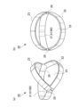
- FIG. 1A and 1B are diagrams schematically showing the electroencephalogram measurement device 1 attached to the subject's head 99
- FIG. is a perspective view.
- the electrode part 10 is removed and shown.
- 2A and 2B are diagrams schematically showing the electroencephalogram measurement apparatus 1, FIG. 2A being a perspective view seen from the front side, and FIG. 2B being a perspective view seen from the rear side.
- 3A and 3B are diagrams schematically showing the frame 20, FIG. 3A being a perspective view seen from the rear side, and FIG. 3B being a perspective view seen from the rear side.
- FIG. 1A and 1B are diagrams schematically showing the electroencephalogram measurement device 1 attached to the subject's head 99
- FIG. is a perspective view.
- the electrode part 10 is removed and shown.
- 2A and 2B are diagrams schematically showing the electroencephalogram measurement apparatus 1, FIG. 2A being a perspective view seen from the front side, and FIG. 2B being a perspective view seen from the rear side.
- FIG. 4 is a perspective view of the electrode section 10.
- FIG. FIG. 5 is a cross-sectional view schematically showing a state in which the electrode section 10 is attached to the electrode fixing member 70 in the electroencephalogram measurement device 1.
- the inner side will be described as the side facing (contacting) the head 99 in the frame 20, and the outer side will be described as the opposite side (the side not facing the head 99).
- the electroencephalogram measurement device 1 is attached to a person's head 99, detects electroencephalograms as potential fluctuations from the living body, and outputs the detected electroencephalograms to an electroencephalogram display device (not shown).
- the electroencephalogram display device acquires electroencephalograms detected by the electroencephalogram measuring device 1, displays them on a monitor, stores data, and performs well-known electroencephalogram analysis processing.
- the electroencephalogram measurement apparatus 1 includes a frame 20, a sheet-like electrode fixing member 70 attached to an opening 25 on the occipital side of the frame 20, and an electrode section 10 attached to the electrode fixing member 70.
- the elastic electrode fixing member 70 extends along the shape of the head 99 (occipital region).
- the electrode section 10 attached to the electrode fixing member 70 is pressed against the head 99 with an appropriate force by the elastic force of the electrode fixing member 70 .
- the frame 20 has a mounting adjustment portion 90 which is provided on the frame 20 and which has an elastic member and which can adjust the contact state of the electrode portion 10 with the head portion 99 .
- a mounting adjustment portion 90 which is provided on the frame 20 and which has an elastic member and which can adjust the contact state of the electrode portion 10 with the head portion 99 .
- the wearing adjustment section 90 a configuration having a top-of-the-head wearing adjustment section 92 that mainly adjusts the wearing state in the head circumference direction will be described. A specific description will be given below.
- the frame 20 is provided along the forehead, temporal region, and occipital region of the head 99 using a frame-shaped (belt-shaped) rigid member, flexible member, elastic member, or a combination thereof.
- hard materials include thermoplastic resins (ABS, PE, PA, PBT, PC, PEEK, PEI, PET, PMMA, POM, PP, PPS, PS) and thermosetting resins (phenol resin, epoxy resin, urea resin, melamine resin), metals (aluminum, copper, stainless steel), etc. can be used.
- Flexible materials include PET film, PE film, PP film, PVC film, PEN film, PI film, vegetable fiber cloth (cotton, morning), animal fiber cloth (silk, wool, alpaca, angora, cashmere, mohair), synthetic fiber Cloth (PE, PA, PC, PES), carbon fiber cloth, aramid fiber cloth, aluminum plate, SUS plate, copper plate, etc. can be used. Silicone rubber, TPS, TPO, TPVC, TPU, TPEE, TPAE, natural rubber, synthetic rubber, chloroprene rubber, urethane rubber, and fluororubber can be used as the elastic member.
- the frame 20 has a front peripheral band member 21 , a rear peripheral frame 22 and a top frame 23 .
- the front peripheral band member 21 and the rear peripheral frame 22 are connected by two connecting portions 29 positioned at the temporal region of the head 99 when worn, and are connected around the head 99 (forehead, temporal region) in the connected state. part, back of the head).
- the top frame 23 extends from the two connecting portions 29 and is curved along the top of the head 99 .
- the front peripheral band member 21 is a stretchable belt-like member provided along the forehead of the forehead, in other words, extending in the head circumference direction (forehead side).
- the front peripheral band member 21 extends according to the head circumference, so that the wearing state in the head circumference direction is properly tightened. It functions as the head circumference mounting adjustment part 91 to be adjusted.
- the material of the front peripheral band member 21 is not particularly limited as long as it can follow the shape of the head circumference and has elasticity. flat rubber).
- the stretchable portion may be a part.
- the rear peripheral frame 22 is made of a hard member such as polyamide resin, and is curved along the shape of the back of the head and provided in a frame shape (belt shape) having a predetermined width.
- the top frame 23 is made of a hard material such as polyamide resin, and is curved along the shape of the temporal region to the top of the head and provided in a frame shape (belt shape) with a predetermined width. .
- Electrode fixing member 70 The posterior peripheral frame 22 and the top frame 23 described above form an opening 25 on the occipital side so as to surround them.
- An electrode fixing member 70 is attached to the top frame 23 and the rear peripheral frame 22 and closes the opening 25 .
- the electrode fixing member 70 is configured with a stretchable sheet material.
- the thickness of the sheet material is not particularly limited, but it is preferable that the thickness be such that it can be stretched sufficiently when attached to the head 99 and has the strength not to break even in continuous use. can do.
- a rubber-like elastic member can be used as the material of the sheet material.
- the material can be the same as the material of the electrode portion 10 to be described later.
- the electrode fixing member 70 may be detachable from the frame 20 (more specifically, the rear peripheral frame 22 and the top frame 23), and the mounting position thereof may be adjustable.
- Various mechanisms such as a hook-and-loop fastener mechanism, a button fitting mechanism, and a screw fitting mechanism can be adopted as the attachment/detachment mechanism.
- the electrode fixing member 70 and the frame 20 may be integrally made of the same material (eg, silicone rubber).
- the portions to be the frame 20 are thick and have a substantially non-stretchable structure, and the portions to be the electrode fixing members 70 are thin and stretchable.
- the electrode fixing member 70 has a plurality of electrode mounting members 75 for mounting the electrode section 10 at predetermined positions (electrode positions based on the 10-20 arrangement method).
- electrode mounting members 75 are provided at four electrode positions P3, P4, O1, and O2 in the 10-20 arrangement method.
- the electrode attachment member 75 has a substantially donut shape with a through hole 76 in the center when viewed from above.
- a male snap button 53 of the electrode section 10 which will be described later, is inserted through the through hole 76 from the inside toward the outside.
- FIG. 4 shows a perspective view of the electrode section 10.
- FIG. 5 shows a sectional view of the state where the electrode section 10 is attached to the electrode mounting member 75 of the electrode fixing member 70.
- FIG. 4 shows a perspective view of the electrode section 10.
- FIG. 5 shows a sectional view of the state where the electrode section 10 is attached to the electrode mounting member 75 of the electrode fixing member 70.
- the electrode section 10 has an electrode section main body 30 and a cap-integrated snap button 50 .
- the cap-integrated snap button 50 is electrically conductive, has a cylindrical shape with a bottom, and functions as a holder that accommodates the electrode unit main body 30 therein, and functions as a connection unit that connects to an external measurement unit.
- the electrode portion main body 30 is fixed inside the tubular shape of the cap-integrated snap button 50 with a silicone adhesive or the like.
- the electrode portion main body 30 has a base portion 31 , a protrusion portion 32 , a conductive contact portion 33 and a signal line portion 34 .
- the base portion 31 and the projection portion 32 are integrally provided by a rubber-like elastic member. A specific material for the elastic member will be described later. Note that the base portion 31 and the projection portion 32 are not limited to being provided integrally, and may be provided separately and assembled with an adhesive or a fitting structure.
- the base 31 has a substantially cylindrical shape.
- a plurality of substantially conical protrusions 32 protruding downward in the drawing are provided at predetermined intervals in the circular circumferential direction on a circular base lower surface 36 on one end side (lower side in the drawing) of the base 31 .
- the shape of the protrusion 32 is not limited to a conical shape, and various shapes such as a pyramid such as a triangular pyramid and a cylindrical shape can be adopted.
- a conductive contact portion 33 is provided on at least the tip side surface of the protruding portion 32 .
- a conductive contact portion 33 may be provided over the entire surface of the protrusion 32 .
- the outer diameter of the base 31 is, for example, 10 mm to 50 mm.
- the height (thickness) of the base 31 is, for example, 2 mm to 30 mm.
- the height of the protrusion 32 is, for example, 3 mm to 15 mm.
- the width of the protrusion 32 (the outer diameter of the root portion) is, for example, 1 mm to 10 mm.
- the electrode portion body 30 is provided with a signal line portion 34 as a signal path connected to the conductive contact portion 33 .
- Various wiring structures can be employed for the signal line portion 34 as long as they are in a manner that conducts through the base portion 31 and the projection portion 32 .
- the signal line portion 34 is provided so as to pass from the conductive contact portion 33 at the tip of the protrusion 32 through the inside of the protrusion 32 and the base portion 31 and be exposed on the base upper surface 35 of the base portion 31 .
- the tip of the signal line portion 34 has a protruded structure, a structure that is substantially on the same plane, or a structure that is buried with respect to the tip portion of the protrusion 32 or its vicinity, that is, the region where the conductive contact portion 33 is formed.
- a projecting structure may be used.
- a projecting portion at the tip of the signal line portion 34 is partially or entirely covered with the conductive contact portion 33 .
- the protruding structure of the tip of the signal line portion 34 may be unfolded, folded, or wrapped around the surface of the tip of the projection 32 .
- a structure provided on the surfaces of the projection portion 32 and the base portion 31 may be used, or a wiring structure may be used in which a portion is provided inside and a portion is provided on the surface.
- the electrode portion main body 30 (the base portion 31 and the projection portion 32) and the electrode fixing member 70 can be made of a rubber-like elastic body as described above.
- the rubber-like elastic body is rubber or a thermoplastic elastomer (also simply referred to as “elastomer (TPE)”). Examples of rubber include silicone rubber.
- thermoplastic elastomers examples include styrene-based TPE (TPS), olefin-based TPE (TPO), vinyl chloride-based TPE (TPVC), urethane-based TPE (TPU), ester-based TPE (TPEE), and amide-based TPE (TPAE).
- TPS styrene-based TPE
- TPO olefin-based TPE
- TPVC vinyl chloride-based TPE
- TPU urethane-based TPE
- TPEE ester-based TPE
- TPAE amide-based TPE
- the type A durometer hardness of the surface of the electrode body 30 measured in accordance with JIS K 6253 (1997) at 37° C.
- the hardness is A
- the rubber hardness A is, for example, 15 or more and 55 or less.
- the silicone rubber-based curable composition will be described.
- the silicone rubber can be composed of a cured product of a silicone rubber-based curable composition.
- the curing step of the silicone rubber-based curable resin composition is, for example, heating at 100 to 250° C. for 1 to 30 minutes (primary curing), followed by post-baking (secondary curing) at 100 to 200° C. for 1 to 4 hours. It is done by
- An insulating silicone rubber is a silicone rubber that does not contain a conductive filler
- a conductive silicone rubber is a silicone rubber that contains a conductive filler
- the silicone rubber-based curable composition according to this embodiment can contain a vinyl group-containing organopolysiloxane (A).
- the vinyl group-containing organopolysiloxane (A) is a polymer that is the main component of the silicone rubber-based curable composition of the present embodiment.
- the insulating silicone rubber-based curable composition and the conductive silicone rubber-based curable composition may contain the same vinyl group-containing linear organopolysiloxane.
- the vinyl group-containing linear organopolysiloxane of the same kind includes at least the same vinyl group with the same functional group and has a linear shape. can be different.
- the insulating silicone rubber-based curable composition and the conductive silicone rubber-based curable composition may further contain different vinyl group-containing organopolysiloxanes.
- the vinyl group-containing organopolysiloxane (A) can contain a vinyl group-containing linear organopolysiloxane (A1) having a linear structure.
- the vinyl group-containing linear organopolysiloxane (A1) has a linear structure and contains vinyl groups, and the vinyl groups serve as cross-linking points during curing.
- the vinyl group content of the vinyl group-containing linear organopolysiloxane (A1) is not particularly limited, but for example, it preferably has two or more vinyl groups in the molecule and is 15 mol % or less. , 0.01 to 12 mol %.
- the amount of vinyl groups in the vinyl group-containing linear organopolysiloxane (A1) is optimized, and a network can be reliably formed with each component described later.
- "-" means including both numerical values.
- the vinyl group content is the mol % of the vinyl group-containing siloxane units when the total units constituting the vinyl group-containing linear organopolysiloxane (A1) are taken as 100 mol %. .
- one vinyl group is considered to be one vinyl group-containing siloxane unit.
- the degree of polymerization of the vinyl group-containing linear organopolysiloxane (A1) is not particularly limited, it is, for example, preferably in the range of about 1,000 to 10,000, more preferably in the range of about 2,000 to 5,000.
- the degree of polymerization can be determined, for example, as a polystyrene-equivalent number-average polymerization degree (or number-average molecular weight) in GPC (gel permeation chromatography) using chloroform as a developing solvent.
- the specific gravity of the vinyl group-containing linear organopolysiloxane (A1) is not particularly limited, but is preferably in the range of about 0.9 to 1.1.
- the heat resistance, flame retardancy, chemical stability, etc. of the resulting silicone rubber can be improved by using those having the degree of polymerization and specific gravity within the ranges described above. can be improved.
- vinyl group-containing linear organopolysiloxane (A1) those having a structure represented by the following formula (1) are particularly preferable.
- R 1 is a substituted or unsubstituted alkyl group, alkenyl group, aryl group, or a hydrocarbon group of a combination thereof having 1 to 10 carbon atoms.
- the alkyl group having 1 to 10 carbon atoms includes, for example, methyl group, ethyl group, propyl group, etc. Among them, methyl group is preferable.
- the alkenyl group having 1 to 10 carbon atoms includes, for example, vinyl group, allyl group, butenyl group, etc. Among them, vinyl group is preferred.
- the aryl group having 1 to 10 carbon atoms includes, for example, a phenyl group.
- R 2 is a substituted or unsubstituted alkyl group, alkenyl group, aryl group having 1 to 10 carbon atoms, or a hydrocarbon group combining these.
- the alkyl group having 1 to 10 carbon atoms includes, for example, methyl group, ethyl group, propyl group, etc. Among them, methyl group is preferable.
- alkenyl groups having 1 to 10 carbon atoms include vinyl groups, allyl groups and butenyl groups.
- the aryl group having 1 to 10 carbon atoms include a phenyl group.
- R 3 is a substituted or unsubstituted alkyl group having 1 to 8 carbon atoms, an aryl group, or a hydrocarbon group combining these.
- the alkyl group having 1 to 8 carbon atoms includes, for example, methyl group, ethyl group, propyl group, etc. Among them, methyl group is preferable.
- Examples of the aryl group having 1 to 8 carbon atoms include a phenyl group.
- examples of substituents for R 1 and R 2 in formula (1) include methyl group and vinyl group, and examples of substituents for R 3 include methyl group.
- a plurality of R 1 are independent of each other and may be different from each other or may be the same. Furthermore, the same applies to R 2 and R 3 .
- m and n are the numbers of repeating units constituting the vinyl group-containing linear organopolysiloxane (A1) represented by formula (1), m is an integer of 0 to 2000, and n is 1000 to 10000. is an integer of m is preferably 0-1000 and n is preferably 2000-5000.
- vinyl group-containing linear organopolysiloxane (A1) represented by formula (1) include, for example, those represented by the following formula (1-1).
- R 1 and R 2 are each independently a methyl group or a vinyl group, and at least one is a vinyl group.
- the vinyl group-containing linear organopolysiloxane (A1) a first vinyl group-containing vinyl group having a vinyl group content of 2 or more vinyl groups in the molecule and not more than 0.4 mol% It contains a linear organopolysiloxane (A1-1) and a second vinyl group-containing linear organopolysiloxane (A1-2) having a vinyl group content of 0.5 to 15 mol%. It is preferable to have As crude rubber, which is a raw material of silicone rubber, a first vinyl group-containing linear organopolysiloxane (A1-1) having a general vinyl group content and a second vinyl group-containing linear organopolysiloxane having a high vinyl group content were used.
- the vinyl groups can be unevenly distributed, and the crosslink density can be more effectively formed in the crosslink network of the silicone rubber. As a result, the tear strength of silicone rubber can be increased more effectively.
- the vinyl group-containing linear organopolysiloxane (A1) for example, a unit in which R 1 is a vinyl group and/or a unit in which R 2 is a vinyl group in the above formula (1-1) , a first vinyl group-containing linear organopolysiloxane (A1-1) having two or more in the molecule and containing 0.4 mol% or less, and a unit in which R 1 is a vinyl group and / or R It is preferable to use a second vinyl group-containing linear organopolysiloxane (A1-2) containing 0.5 to 15 mol % of units in which 2 is a vinyl group.
- the first vinyl group-containing linear organopolysiloxane (A1-1) preferably has a vinyl group content of 0.01 to 0.2 mol %.
- the second vinyl group-containing linear organopolysiloxane (A1-2) preferably has a vinyl group content of 0.8 to 12 mol %.
- (A1-1) and (A1-2) are not particularly limited, but for example, the weight ratio of (A1-1):(A1-2) is preferably 50:50 to 95:5, and 80:20 to 90: 10 is more preferred.
- the first and second vinyl group-containing linear organopolysiloxanes (A1-1) and (A1-2) may be used singly or in combination of two or more. good.
- the vinyl group-containing organopolysiloxane (A) may contain a vinyl group-containing branched organopolysiloxane (A2) having a branched structure.
- the silicone rubber-based curable composition of the present embodiment may contain a cross-linking agent.
- Cross-linking agents can include organohydrogenpolysiloxanes (B).
- Organohydrogenpolysiloxane (B) is classified into linear organohydrogenpolysiloxane (B1) having a linear structure and branched organohydrogenpolysiloxane (B2) having a branched structure. Either or both may be included.
- the insulating silicone rubber-based curable composition and the conductive silicone rubber-based curable composition may contain the same type of cross-linking agent.
- the same type of cross-linking agent should have at least a common structure such as a linear structure or a branched structure, and may contain different molecular weight distributions and different functional groups in the molecule, and the amount added may be different.
- the insulating silicone rubber-based curable composition and the conductive silicone rubber-based curable composition may further contain different cross-linking agents.
- the linear organohydrogenpolysiloxane (B1) has a linear structure and a structure ( ⁇ Si—H) in which hydrogen is directly bonded to Si, and is the vinyl group-containing organopolysiloxane (A). It is a polymer that undergoes a hydrosilylation reaction with vinyl groups other than vinyl groups contained in other components of the silicone rubber-based curable composition, thereby cross-linking these components.
- the molecular weight of the linear organohydrogenpolysiloxane (B1) is not particularly limited, for example, the weight average molecular weight is preferably 20,000 or less, more preferably 1,000 or more and 10,000 or less.
- the weight average molecular weight of the linear organohydrogenpolysiloxane (B1) can be measured, for example, by polystyrene conversion in GPC (gel permeation chromatography) using chloroform as a developing solvent.
- the linear organohydrogenpolysiloxane (B1) does not have a vinyl group. Thereby, it is possible to accurately prevent the progress of the cross-linking reaction in the molecule of the linear organohydrogenpolysiloxane (B1).
- linear organohydrogenpolysiloxane (B1) for example, one having a structure represented by the following formula (2) is preferably used.
- R 4 is a substituted or unsubstituted alkyl group, alkenyl group, aryl group having 1 to 10 carbon atoms, a hydrocarbon group combining these groups, or a hydride group.
- the alkyl group having 1 to 10 carbon atoms includes, for example, methyl group, ethyl group, propyl group, etc. Among them, methyl group is preferable.
- alkenyl groups having 1 to 10 carbon atoms include vinyl groups, allyl groups and butenyl groups.
- the aryl group having 1 to 10 carbon atoms include a phenyl group.
- R 5 is a substituted or unsubstituted alkyl group, alkenyl group, aryl group having 1 to 10 carbon atoms, a hydrocarbon group combining these, or a hydride group.
- alkyl group having 1 to 10 carbon atoms include methyl group, ethyl group and propyl group, with methyl group being preferred.
- alkenyl groups having 1 to 10 carbon atoms include vinyl groups, allyl groups and butenyl groups.
- Examples of the aryl group having 1 to 10 carbon atoms include a phenyl group.
- a plurality of R 4 are independent of each other and may be different from each other or may be the same. The same is true for R5 . However, at least two or more of the plurality of R 4 and R 5 are hydride groups.
- R 6 is a substituted or unsubstituted alkyl group having 1 to 8 carbon atoms, an aryl group, or a hydrocarbon group combining these.
- the alkyl group having 1 to 8 carbon atoms includes, for example, methyl group, ethyl group, propyl group, etc. Among them, methyl group is preferable.
- Examples of the aryl group having 1 to 8 carbon atoms include a phenyl group.
- a plurality of R 6 are independent from each other and may be different from each other or may be the same.
- substituents for R 4 , R 5 and R 6 in formula (2) include methyl group and vinyl group, with methyl group being preferred from the viewpoint of preventing intramolecular cross-linking reaction.
- m and n are the numbers of repeating units constituting the linear organohydrogenpolysiloxane (B1) represented by formula (2), m is an integer of 2 to 150, and n is an integer of 2 to 150. is.
- m is an integer from 2-100 and n is an integer from 2-100.
- the straight-chain organohydrogenpolysiloxane (B1) may be used alone or in combination of two or more.
- the branched organohydrogenpolysiloxane (B2) has a branched structure, it is a component that forms regions with a high crosslink density and greatly contributes to the formation of a loose and dense structure of crosslink density in the silicone rubber system. Further, like the linear organohydrogenpolysiloxane (B1), it has a structure ( ⁇ Si—H) in which hydrogen is directly bonded to Si, and in addition to the vinyl group of the vinyl group-containing organopolysiloxane (A), silicone It is a polymer that undergoes a hydrosilylation reaction with the vinyl groups of the components blended in the rubber-based curable composition to crosslink these components.
- the specific gravity of the branched organohydrogenpolysiloxane (B2) is in the range of 0.9 to 0.95.
- the branched organohydrogenpolysiloxane (B2) does not have a vinyl group. Thereby, it is possible to accurately prevent the progress of the cross-linking reaction in the molecule of the branched organohydrogenpolysiloxane (B2).
- branched organohydrogenpolysiloxane (B2) one represented by the following average compositional formula (c) is preferable.
- R 7 is a monovalent organic group, a is an integer ranging from 1 to 3, m is the number of H a (R 7 ) 3-a SiO 1/2 units, n is SiO 4/ is a number of 2 units)
- R 7 is a monovalent organic group, preferably a substituted or unsubstituted alkyl group having 1 to 10 carbon atoms, an aryl group, or a hydrocarbon group combining these.
- the alkyl group having 1 to 10 carbon atoms includes, for example, methyl group, ethyl group, propyl group, etc. Among them, methyl group is preferable.
- Examples of the aryl group having 1 to 10 carbon atoms include a phenyl group.
- a is the number of hydride groups (hydrogen atoms directly bonded to Si) and is an integer in the range of 1 to 3, preferably 1.
- m is the number of H a (R 7 ) 3-a SiO 1/2 units
- n is the number of SiO 4/2 units.
- the branched organohydrogenpolysiloxane (B2) has a branched structure.
- the linear organohydrogenpolysiloxane (B1) and the branched organohydrogenpolysiloxane (B2) differ in that their structures are linear or branched.
- the number of bound alkyl groups R (R/Si) is 1.8 to 2.1 for the linear organohydrogenpolysiloxane (B1) and 0.8 to 1 for the branched organohydrogenpolysiloxane (B2). .7 range.
- the branched organohydrogenpolysiloxane (B2) has a branched structure, for example, when heated to 1000° C. at a heating rate of 10° C./min in a nitrogen atmosphere, the residual amount is 5% or more. becomes.
- the straight-chain organohydrogenpolysiloxane (B1) is straight-chain, the amount of residue after heating under the above conditions is almost zero.
- branched organohydrogenpolysiloxane (B2) include those having a structure represented by the following formula (3).
- R 7 is a substituted or unsubstituted alkyl group having 1 to 8 carbon atoms, an aryl group, a hydrocarbon group combining these, or a hydrogen atom.
- the alkyl group having 1 to 8 carbon atoms includes, for example, methyl group, ethyl group, propyl group, etc. Among them, methyl group is preferred.
- Examples of the aryl group having 1 to 8 carbon atoms include a phenyl group.
- the substituent of R7 include a methyl group and the like.
- a plurality of R 7 are independent of each other and may be different from each other or may be the same.
- the branched organohydrogenpolysiloxane (B2) may be used alone or in combination of two or more.
- the amount of hydrogen atoms (hydride groups) directly bonded to Si is not particularly limited.
- linear organohydrogenpolysiloxane (B1) and branched organohydrogenpolysiloxane are The total amount of hydride groups in the siloxane (B2) is preferably from 0.5 to 5 mol, more preferably from 1 to 3.5 mol.
- the silicone rubber-based curable composition according to this embodiment contains a non-conductive filler.
- the non-conductive filler may contain silica particles (C) as needed. Thereby, the hardness and mechanical strength of the elastomer can be improved.
- the insulating silicone rubber-based curable composition and the conductive silicone rubber-based curable composition may contain the same type of non-conductive filler.
- Non-conductive fillers of the same type may have at least common constituent materials, and may differ in particle size, specific surface area, surface treatment agent, or addition amount thereof.
- the insulating silicone rubber-based curable composition and the conductive silicone rubber-based curable composition may further contain different silane coupling agents.
- the silica particles (C) are not particularly limited, but for example, fumed silica, calcined silica, precipitated silica, etc. are used. These may be used alone or in combination of two or more.
- the silica particles (C) preferably have a BET specific surface area of, for example, 50 to 400 m 2 /g, more preferably 100 to 400 m 2 /g. Also, the average primary particle size of the silica particles (C) is preferably, for example, 1 to 100 nm, more preferably about 5 to 20 nm.
- silica particles (C) having a specific surface area and an average particle size within the above ranges, the hardness and mechanical strength of the formed silicone rubber can be improved, especially the tensile strength can be improved.
- the silicone rubber-based curable composition of the present embodiment can contain a silane coupling agent (D).
- Silane coupling agent (D) can have a hydrolyzable group. The hydrolyzable group is hydrolyzed with water to form a hydroxyl group, and the hydroxyl group undergoes a dehydration condensation reaction with the hydroxyl group on the surface of the silica particle (C), thereby modifying the surface of the silica particle (C).
- the insulating silicone rubber-based curable composition and the conductive silicone rubber-based curable composition may contain the same type of silane coupling agent.
- the silane coupling agents of the same kind should have at least a common functional group, and may differ in other functional groups in the molecule and in the amount added.
- the insulating silicone rubber-based curable composition and the conductive silicone rubber-based curable composition may further contain different silane coupling agents.
- this silane coupling agent (D) can contain a silane coupling agent having a hydrophobic group.
- the hydrophobic group is imparted to the surface of the silica particles (C), so that the cohesive force of the silica particles (C) in the silicone rubber-based curable composition and further in the silicone rubber is reduced (hydrogen aggregation due to bonding is reduced), and as a result, it is assumed that the dispersibility of the silica particles (C) in the silicone rubber-based curable composition is improved. This increases the interface between the silica particles (C) and the rubber matrix, increasing the reinforcing effect of the silica particles (C).
- the slipperiness of the silica particles (C) within the matrix is improved when the rubber matrix is deformed.
- the improved dispersibility and slipperiness of the silica particles (C) improve the mechanical strength (for example, tensile strength and tear strength) of the silicone rubber due to the silica particles (C).
- the silane coupling agent (D) can contain a silane coupling agent having a vinyl group.
- vinyl groups are introduced onto the surfaces of the silica particles (C). Therefore, during curing of the silicone rubber-based curable composition, that is, a hydrosilylation reaction occurs between the vinyl group of the vinyl group-containing organopolysiloxane (A) and the hydride group of the organohydrogenpolysiloxane (B). , When a network (crosslinked structure) is formed by these, the vinyl groups possessed by the silica particles (C) also participate in the hydrosilylation reaction with the hydride groups possessed by the organohydrogenpolysiloxane (B). Silica particles (C) also come to be taken in. As a result, it is possible to reduce the hardness and increase the modulus of the formed silicone rubber.
- silane coupling agent (D) a silane coupling agent having a hydrophobic group and a silane coupling agent having a vinyl group can be used in combination.
- silane coupling agent (D) examples include those represented by the following formula (4).
- n represents an integer of 1-3.
- Y represents a functional group having a hydrophobic group, a hydrophilic group or a vinyl group, and when n is 1 it is a hydrophobic group, and when n is 2 or 3 at least one of It is a hydrophobic group.
- X represents a hydrolyzable group.
- the hydrophobic group is an alkyl group having 1 to 6 carbon atoms, an aryl group, or a hydrocarbon group having a combination thereof, and examples thereof include a methyl group, an ethyl group, a propyl group, a phenyl group, and the like. Methyl groups are preferred.
- the hydrophilic group includes, for example, a hydroxyl group, a sulfonic acid group, a carboxyl group, a carbonyl group, etc. Among them, a hydroxyl group is particularly preferable.
- the hydrophilic group may be contained as a functional group, but is preferably not contained from the viewpoint of imparting hydrophobicity to the silane coupling agent (D).
- the hydrolyzable group includes an alkoxy group such as a methoxy group and an ethoxy group, a chloro group, a silazane group, and the like.
- a silazane group is preferable because of its high reactivity with the silica particles (C).
- a compound having a silazane group as a hydrolyzable group has two structures of (Y n —Si—) in the above formula (4) due to its structural characteristics.
- silane coupling agent (D) represented by the above formula (4) are as follows.
- Those having a hydrophobic group as the functional group include, for example, methyltrimethoxysilane, dimethyldimethoxysilane, phenyltrimethoxysilane, methyltriethoxysilane, dimethyldiethoxysilane, phenyltriethoxysilane, n-propyltrimethoxysilane, alkoxysilanes such as n-propyltriethoxysilane, hexyltrimethoxysilane, hexyltriethoxysilane, decyltrimethoxysilane; chlorosilanes such as methyltrichlorosilane, dimethyldichlorosilane, trimethylchlorosilane, phenyltrichlorosilane; hexamethyldisilazane.
- silane coupling agent having a trimethylsilyl group containing at least one selected from the group consisting of hexamethyldisilazane, trimethylchlorosilane, trimethylmethoxysilane, and trimethylethoxysilane is preferred.
- Examples of those having a vinyl group as the functional group include methacryloxypropyltriethoxysilane, methacryloxypropyltrimethoxysilane, methacryloxypropylmethyldiethoxysilane, methacryloxypropylmethyldimethoxysilane, vinyltriethoxysilane, and vinyltrimethoxysilane.
- alkoxysilanes such as silane and vinylmethyldimethoxysilane
- chlorosilanes such as vinyltrichlorosilane and vinylmethyldichlorosilane
- divinyltetramethyldisilazane divinyltetramethyldisilazane.
- a silane coupling agent having a vinyl group-containing organosilyl group containing one or more selected from the group consisting of methyldimethoxysilane is preferred.
- silane coupling agent (D) contains two kinds of a silane coupling agent having a trimethylsilyl group and a silane coupling agent having a vinyl group-containing organosilyl group
- those having a hydrophobic group include hexamethyldisilazane, Divinyltetramethyldisilazane is preferably included as one having a vinyl group.
- the ratio of (D1) and (D2) is not particularly limited, but for example, (D1):(D2) in a weight ratio of 1:0.001 to 1:0.35, preferably 1:0.01 to 1:0.20, more preferably 1:0.03 to 1:0 .15. Desired physical properties of the silicone rubber can be obtained by setting it to such a numerical range. Specifically, the dispersibility of silica in the rubber and the crosslinkability of the rubber can be balanced.
- the lower limit of the content of the silane coupling agent (D) is preferably 1% by mass or more with respect to 100 parts by weight of the total amount of the vinyl group-containing organopolysiloxane (A). It is more preferably at least 5% by mass, even more preferably at least 5% by mass.
- the upper limit of the content of the silane coupling agent (D) is preferably 100% by mass or less, and 80% by mass or less with respect to 100 parts by weight of the total amount of the vinyl group-containing organopolysiloxane (A). It is more preferable that the content is 40% by mass or less.
- the silicone rubber can have appropriate mechanical properties.
- the silicone rubber-based curable composition according to this embodiment may contain a catalyst.
- the catalyst may contain platinum or a platinum compound (E).
- Platinum or a platinum compound (E) is a catalytic component that acts as a catalyst during curing.
- the amount of platinum or platinum compound (E) added is a catalytic amount.
- the insulating silicone rubber-based curable composition and the conductive silicone rubber-based curable composition may contain the same type of catalyst. Catalysts of the same kind may have at least common constituent materials, and the catalysts may contain different compositions and may differ in addition amount.
- the insulating silicone rubber-based curable composition and the conductive silicone rubber-based curable composition may further contain different catalysts.
- platinum or platinum compound (E) a known one can be used, for example, platinum black, platinum supported on silica or carbon black, chloroplatinic acid or an alcohol solution of chloroplatinic acid, A complex salt of platinic acid and olefin, a complex salt of chloroplatinic acid and vinyl siloxane, and the like are included.
- the platinum or platinum compound (E) may be used alone or in combination of two or more.
- the content of platinum or platinum compound (E) in the silicone rubber-based curable composition means the amount of catalyst, and can be set as appropriate.
- (A), silica particles (C), the total amount of 100 parts by weight of the silane coupling agent (D), platinum group metal is an amount of 0.01 to 1000 ppm by weight unit, preferably 0. The amount is 1 to 500 ppm.
- the silicone rubber-based curable composition according to the present embodiment may contain water (F) in addition to the above components (A) to (E).
- Water (F) is a component that functions as a dispersion medium for dispersing each component contained in the silicone rubber-based curable composition and contributes to the reaction between the silica particles (C) and the silane coupling agent (D). . Therefore, the silica particles (C) and the silane coupling agent (D) can be linked to each other more reliably in the silicone rubber, and uniform properties can be exhibited as a whole.
- the silicone rubber-based curable composition of the present embodiment may further contain other components in addition to the above components (A) to (F).
- Other components include silica particles (C) such as diatomaceous earth, iron oxide, zinc oxide, titanium oxide, barium oxide, magnesium oxide, cerium oxide, calcium carbonate, magnesium carbonate, zinc carbonate, glass wool, and mica.
- additives such as inorganic fillers, reaction inhibitors, dispersants, pigments, dyes, antistatic agents, antioxidants, flame retardants, and thermal conductivity improvers.
- the conductive solution (conductive silicone rubber composition) according to the present embodiment contains the conductive filler and solvent in addition to the silicone rubber-based curable composition containing no conductive filler.
- solvents can be used as the solvent, and for example, a high boiling point solvent can be included. These may be used alone or in combination of two or more.
- solvents examples include aliphatic hydrocarbons such as pentane, hexane, cyclohexane, heptane, methylcyclohexane, ethylcyclohexane, octane, decane, dodecane, and tetradecane; benzene, toluene, ethylbenzene, xylene, trifluoromethylbenzene; , aromatic hydrocarbons such as benzotrifluoride; diethyl ether, diisopropyl ether, dibutyl ether, cyclopentyl methyl ether, cyclopentyl ethyl ether, ethylene glycol dimethyl ether, ethylene glycol diethyl ether, diethylene glycol dimethyl ether, 1,4-dioxane, 1,3 - ethers such as dioxane and tetrahydrofuran; haloalkanes such as
- the conductive solution can have a viscosity suitable for various coating methods such as spray coating and dip coating.
- the lower limit of the content of the silica particles (C) contained in the electrode portion main body 30 is the silica particles (C) and the conductive filler
- the upper limit of the content of the silica particles (C) contained in the electrode portion main body 30 is, for example, 20% by mass or less with respect to 100% by mass of the total amount of the silica particles (C) and the conductive filler. , preferably 15% by mass or less, more preferably 10% by mass or less.
- a conductive silicone rubber can be obtained by heating and drying the conductive solution as necessary.
- the conductive silicone rubber may be configured without silicone oil. As a result, it is possible to prevent the silicone oil from bleeding out on the surface of the electrode portion main body 30 to reduce the conductivity.
- the signal line portion 34 can use a known one, and can be made of conductive fiber, for example.
- conductive fiber one or more selected from the group consisting of metal fiber, metal-coated fiber, carbon fiber, conductive polymer fiber, conductive polymer-coated fiber, and conductive paste-coated fiber can be used. These may be used alone or in combination of two or more.
- the metal material of the metal fibers and metal-coated fibers is not limited as long as it has conductivity, but copper, silver, gold, nickel, tin, lead, zinc, bismuth, antimony, stainless steel, aluminum, silver/chloride silver and alloys thereof; These may be used alone or in combination of two or more. Among these, silver can be used from the viewpoint of conductivity. Moreover, it is preferable that the metal material does not contain a metal such as chromium that causes a load on the environment.
- the fiber materials of the metal-coated fibers, conductive polymer-coated fibers, and conductive paste-coated fibers are not particularly limited, but may be synthetic fibers, semi-synthetic fibers, or natural fibers. Among these, it is preferable to use polyester, nylon, polyurethane, silk, cotton, and the like. These may be used alone or in combination of two or more.
- Examples of the carbon fibers include PAN-based carbon fibers and pitch-based carbon fibers.
- the conductive polymer material of the conductive polymer fiber and the conductive polymer-coated fiber is, for example, a mixture of a conductive polymer such as polythiophene, polypyrrole, polyaniline, polyacetylene, polyphenylene vinylene, polynaphthalene, and derivatives thereof and a binder resin, Alternatively, an aqueous solution of a conductive polymer such as PEDOT-PSS ((3,4-ethylenedioxythiophene)-poly(styrenesulfonic acid)) is used.
- PEDOT-PSS ((3,4-ethylenedioxythiophene)-poly(styrenesulfonic acid)
- the resin material contained in the conductive paste of the conductive paste-coated fiber is not particularly limited, but preferably has elasticity. It can contain one or more selected from the group consisting of propylene rubbers. These may be used alone or in combination of two or more.
- the conductive filler contained in the conductive paste of the conductive paste-coated fiber is not particularly limited, and known conductive materials may be used, such as metal particles, metal fibers, metal-coated fibers, carbon black, acetylene black, graphite, carbon It may contain one or more selected from the group consisting of fibers, carbon nanotubes, conductive polymers, conductive polymer-coated fibers and metal nanowires.
- the metal constituting the conductive filler is not particularly limited, but for example, copper, silver, gold, nickel, tin, lead, zinc, bismuth, antimony, silver/silver chloride, or at least one of these alloys. or, alternatively, two or more of these.
- silver or copper is preferable because of its high conductivity and high availability.
- the signal line portion 34 may be composed of twisted yarn obtained by twisting a plurality of linear conductive fibers. As a result, breakage of the signal line portion 34 during deformation can be suppressed.
- the coating of the conductive fiber means not only covering the outer surface of the fiber material, but also, in the case of a twisted yarn obtained by twisting single fibers, a metal or a conductive polymer is added between the fibers in the twisted yarn. , or impregnated with a conductive paste to cover each single fiber constituting the twisted yarn.
- the tensile elongation at break of the signal wire portion 34 is, for example, 1% to 50%, preferably 1.5% to 45%. By setting the value within such a numerical range, it is possible to suppress excessive deformation of the protrusion 32 while suppressing breakage during deformation.
- the conductive member of the conductive contact portion 33 is, for example, a paste containing a highly conductive metal (so-called conductive paste).
- the highly conductive metal includes one or more selected from the group consisting of copper, silver, gold, nickel, tin, lead, zinc, bismuth, antimony, or alloys thereof.
- silver, silver chloride, and copper are suitable from the viewpoint of availability and conductivity.
- the top of the protrusion 32 made of a rubber-like elastic body is dipped (immersed) in a paste-like conductive solution containing a highly conductive metal. Apply). Thereby, a conductive contact portion 33 is formed on the surface of the projection portion 32 .
- the conductive contact portion 33 may be formed as a conductive resin layer by applying a conductive solution containing a conductive filler and a solvent to the projection portion 32 . At this time, by using the same type of material (silicone rubber) as the solvent for the protrusion 32, the adhesion of the conductive contact portion 33 (conductive resin layer) can be enhanced.
- a conductive silicone rubber can be obtained by heating and drying the conductive solution as necessary.
- the conductive silicone rubber may be configured without silicone oil. As a result, it is possible to suppress a decrease in conductivity due to bleeding out of the silicone oil onto the surface of the conductive contact portion 33 .
- the cap-integrated snap button 50 is made of, for example, a good conductor metal, has a cylindrical shape with a bottom, and has connecting means (male snap button 53) on the outer surface of the bottomed portion for connection to an external measuring unit.
- metals that are good conductors include stainless steel, copper alloys, aluminum alloys, and brass.
- the cap-integrated snap button 50 integrally includes a cap top plate 51 which is a bottom surface of a bottomed cylindrical shape, and a cylindrical cap body portion 52 extending downward in the figure from the peripheral edge of the cap top plate 51 . .
- a cylindrical male snap button 53 extending upward in the drawing is provided at the center of the outer surface 56 of the circular cap top plate 51 (that is, the center of the circular shape when viewed from above).
- the base upper surface 35 of the electrode unit main body 30 is attached to the inner surface 54 of the cap top plate 51 via a conductive paste layer so as to be in contact therewith.
- the inner surface 54 of the cap top plate 51 and the upper surface 35 of the base portion are arranged so that the upper end portion of the signal line portion 34 is sandwiched therebetween, as described above.
- the male snap button 53 is an interface to which a signal line is attached for connection with an external measurement unit.
- the male snap button 53 has, for example, a shape of a connection terminal in which the diameter of the cylindrical tip side is larger than that of the base side.
- the male snap button 53 is inserted through the through hole 76 from the inside of the electrode fixing member 70 (electrode attaching member 75), and is a portion with an enlarged diameter projecting outward from the through hole 76.
- the male snap button 53 is a female snap button provided on the signal line. It fits with the snap button 49 .
- the electrode mounting member 75 is sandwiched between the female snap button 49 and the cap top plate 51, and the electrode section 10 is fixed to the electrode fixing member 70 with the projecting section 32 facing inward (head 99 side).
- the front peripheral band member 21 of the frame 20 is stretchable, so that the frame 20 can be easily attached to the head circumference.
- the electrode fixing member 70 to which the electrode sections 10 are attached is provided so as to cover the back of the head, when the electroencephalogram measurement device 1 is worn, all the electrode sections 10 are brought into contact with the head 99 with an appropriate force. can be made That is, it is possible to shorten the time required to bring the electrode section 10 into contact with the head 99 appropriately.
- FIG. 6 shows electroencephalogram measurement apparatuses 1A and 1B having electrode fixing members 70A and 70B of modifications.
- the electrode fixing member 70A is configured with an elastic band member. Specifically, it is provided so as to extend in the horizontal direction (that is, from one temporal side to the other temporal side) in the opening 25 on the occipital side formed by the posterior peripheral frame 22 and the top frame 23 . and a plurality of band members (upper and lower band members 79) provided so as to extend in the vertical direction (direction from the back of the head to the top of the head). are intersected in a grid. This can improve breathability.
- All or part of the horizontal band member 78 and the upper and lower band members 79 may be removable and replaceable with respect to the rear peripheral frame 22 and the top frame 23 .
- the electroencephalogram measurement device 1 may be used with parts of the horizontal band member 78 and the upper and lower band members 79 removed.
- the electrode fixing member 70B is provided with a plurality of through holes 71 in the stretchable sheet member.
- the size of the through-holes 71 is not particularly limited, and all of them may have the same size or may have different sizes.
- FIG. 7 shows a modified front peripheral band member 21A.
- the front peripheral band member 21A has a two-stage fixing mechanism using an elastic member and a hook-and-loop fastener as a structure that functions as a head circumference attachment adjustment portion 91 that adjusts the attachment state in the head circumference direction.
- the fixing mechanism of the first stage is as follows. That is, as shown in FIG. 7(a), the front peripheral band member 21A (head circumference attachment adjustment portion 91) is provided with a stretchable band member extending in the head circumference direction so as to be separable to the left and right. Specifically, the front peripheral band member 21A has a first belt-shaped member 211 (right side in the figure) and a second belt-shaped member 212 (left side in the figure) that are divided in the head circumference direction. The first belt-shaped member 211 and the second belt-shaped member 212 are provided so as to be joined together so that the length in the extending direction can be adjusted.
- a hook-and-loop fastener (hook surface) 213 is provided outwardly at the tip portion (end portion on the left side in the figure) of the first belt-shaped member 211 .
- a hook-and-loop fastener (loop surface) 214 is provided facing inward at the tip portion (end portion on the right side in the drawing) of the second belt-shaped member 212 .
- a hook-and-loop fastener (hook surface) 213 and a hook-and-loop fastener (loop surface) 214 are bonded together.
- auxiliary adjusting section 230 that acts to contract the elastic member of the head circumference attachment adjusting section 91 .
- the first belt-shaped member 211 As a mechanism for adjusting the stretched state of the first belt-shaped member 211, it has an elastic belt-shaped first auxiliary belt-shaped member 217, one end of which is fixed to the mounting portion 221. The other end of the first auxiliary belt-shaped member 217 extends toward the tip of the first belt-shaped member 211 (left side in the drawing).
- a first auxiliary hook surface fastener (hook surface) 215 is provided facing outward in a region on the right side of the hook surface fastener (hook surface) 213 of the first belt-shaped member 211 .
- a first auxiliary surface fastener (loop surface) 219 is provided facing inward as a member to be adhered to the first auxiliary surface fastener (hook surface) 215. .
- FIG. 7(c) by adjusting the bonding position of the first auxiliary surface fastener (loop surface) 219 with respect to the first auxiliary surface fastener (hook surface) 215, the extension of the first auxiliary strip member 217 is achieved. You can adjust the state.
- the second belt-shaped member 212 As a mechanism for adjusting the stretched state of the second belt-shaped member 212, it has an elastic belt-shaped second auxiliary belt-shaped member 218 whose one end is fixed to the mounting portion 222. The other end of the second auxiliary belt-shaped member 218 extends toward the tip of the second belt-shaped member 212 (on the right side in the drawing).
- a second auxiliary hook surface fastener (hook surface) 216 is provided facing outward in a region on the left side of the hook surface fastener (loop surface) 214 of the second belt-shaped member 212 .
- a second auxiliary surface fastener (loop surface) 220 is provided facing inward as a member to be adhered to the second auxiliary surface fastener (hook surface) 216.
- the extension of the second auxiliary strip member 218 is achieved. You can adjust the state.
- a parietal mounting adjustment unit for adjusting the mounting state in the parietal direction may be provided.
- a belt-shaped member or a string-shaped member that tightens the subject's jaw is used as the crown-mounted adjuster.
- the crown mounting adjustment unit is configured such that a stretchable rubber belt-like member or string-like member is attached to the two connecting portions 29 of the frame 20 at both ends thereof, and is mounted on the crown of the head when the electroencephalogram measurement device 1 is mounted. Hook the adjuster on your chin.
- the crown fitting adjustment portion may have an adjustment function by a hook-and-loop fastener mechanism, similar to the front peripheral band member 21A as shown in FIG.
- the electroencephalogram measurement device 1 can act to press the head 99 downward, and the electrode section 10 attached to the electrode fixing member 70 can be moderately pressed against the head 99 .
- FIG. 8 is a diagram schematically showing the electroencephalogram measurement device 1C attached to the subject's head 99.
- FIG. 9 is a plan view schematically showing the electrode fixing member 70C.
- 10A and 10B are diagrams schematically showing the fixing portion 80, in which FIG. 10A is a plan view and FIG. 10B is a side view.
- FIG. 11 is a diagram schematically showing the fixed state of the fixing adjusting portion 60, and particularly shows the state where the first band portion 71 of the electrode fixing member 70C is attached to the rear peripheral frame 22C.
- the electroencephalogram measurement apparatus 1C includes a frame 20C, a band-like (or sheet-like) electrode fixing member 70C attached to an opening 25 on the occipital side of the frame 20C, and an electrode fixing member 70C. It has a fixation adjusting portion 60 that allows adjustment of the state of fixation to the frame 20, and an electrode portion (not shown) attached to the electrode fixing member 70C.
- the difference between the present embodiment and the first embodiment lies in the electrode fixing member 70C and the manner in which the electrode fixing member 70C is attached to the frame 20C (that is, the fixing adjusting portion 60). , and similar configurations and functions will be omitted as appropriate.
- the frame 20C is provided along the forehead, temporal region, and occipital region of the head 99 by combining a frame-shaped (belt-shaped) rigid member and an elastic member. and a top frame 23C.
- the front peripheral band member 21C is a strip-shaped band member having a hook-and-loop fastener mechanism, and is provided so as to be able to adjust the fixed state on the forehead side.
- the top frame 23C is provided so that the top of the head is positioned closer to the forehead than in the first embodiment.
- the rear peripheral frame 22C has insertion portions (the first band insertion portion 27 and the second band insertion portion 28) and the fitting opening 26 as part of the configuration of the fixing adjustment portion 60. (see FIG. 11).
- the electrode fixing member 70C is a Y-shaped band member in plan view when detached from the frame 20C, and is a long band-shaped first band portion 71C extending vertically in the figure. and a long band-shaped second band portion 72C and a third band portion 73C extending obliquely upward in two directions from one end of the upper side of the first band portion 71C in the drawing.
- a material similar to that of the electrode fixing member 70 of the first embodiment can be used as the material of the electrode fixing member 70C.
- the first band portion 71C can have a width of 20 mm and a length of 150 mm, for example.
- the lower end of the first band portion 71C functions as a band adjustment portion 74C that is inserted through and fixed to the first band insertion portion 27 and the second band insertion portion 28 of the frame 20 (rear peripheral frame 22C).
- the second band portion 72C extends diagonally to the upper left in the figure, and the extended end functions as a band attachment portion 77C attached to the top frame 23C.
- the band attachment portion 77C may be fixed to the top frame 23 with screws, strings, or the like.
- the band mounting portion 77C and the top frame 23C may be fixed by providing locking portions to each of them and locking them to each other.
- the second band portion 72C can have a width of 30 mm and a length of 100 mm, for example.
- An electrode attachment member 75 is provided substantially in the center of the second band portion 72C. The position of this electrode mounting member 75 is, for example, the electrode position C3 in the 10-20 arrangement method.
- the third band portion 73C extends obliquely to the upper right in the drawing, and the extended end functions as a band attachment portion 77C attached to the top frame 23C. Also, the band mounting portion 77C and the top frame 23C may be fixed by providing locking portions to each of them and locking them to each other.
- the third band portion 73C can have a width of 30 mm and a length of 100 mm, for example.
- An electrode attachment member 75 is provided substantially in the center of the third band portion 73 . The position of this electrode mounting member 75 is the electrode position C4 in the 10-20 arrangement method.
- the fixation adjusting section 60 adjusts the expansion/contraction state of the electrode fixing member 70C and attaches the electrode fixing member 70C to the frame 20C (the rear peripheral frame 22C).
- the fixing adjustment portion 60 includes insertion portions (the first band insertion portion 27 and the second band insertion portion 28) provided in the above-described frame 20C (the rear peripheral frame 22C), the fitting opening 26, and a fixing portion 80 .
- the rear peripheral frame 22C has a first band insertion portion 27 and a second band insertion portion 28 which are horizontally long openings at the occipital region.
- the first band insertion portion 27 on the upper side and the second band insertion portion 28 on the lower side are arranged vertically.
- the size of the openings of the first band insertion portion 27 and the second band insertion portion 28 is set to a size that allows the band adjustment portion 74 to be inserted therethrough.
- the band adjusting portion 74C of the electrode fixing member 70 is inserted through the first band inserting portion 27 and the second band inserting portion 28, and the fixing portion 80 fixes the band adjusting portion 74 to the rear peripheral frame 22C.
- the fitting openings 26 are through holes arranged horizontally in a zigzag pattern in two vertical rows in the rear peripheral frame 22C.
- the fitting opening 26 has a shape in which the fitting convex portion 83 of the fixing portion 80 described below is just fitted.
- the fixing portion 80 is made of hard plastic, for example, and the electrode fixing member 70C (first band portion 71C) inserted through the insertion portions (first band insertion portion 27, second band insertion portion 28) is attached to the frame 20C (rear peripheral frame). 22C).
- the fixing portion 80 integrally includes a base portion 81 , a support portion 82 , a fitting convex portion 83 , and a band clamping convex portion 84 .
- the base portion 81 is a plate-like plate material, and has support portions 82 near both ends of one surface.
- the support portion 82 has an inclined surface in which the outer side is higher and the central side is lower in the left-right direction.
- this inclined surface presses the band adjusting portion 74 against the rear peripheral frame 22C.
- Columnar fitting protrusions 83 are provided at two locations on the inclined surface of the support portion 82 so as to extend therefrom.
- the fitting convex portion 83 is fitted into the fitting opening 26 of the rear peripheral frame 22 ⁇ /b>C described above when the band adjusting portion 74 is fixed by the fixing portion 80 .
- the band holding projections 84 are provided in a rib-like manner at two locations near the upper and lower outer edges of the base portion 81 so as to face each other.
- the interval between the two band holding protrusions 84 is set to be substantially the same (or slightly wider) than the width of the rear peripheral frame 22C.
- the inclined surface of the support portion 82 of the fixing portion 80 presses the band adjusting portion 74 against the rear peripheral frame 22C, and the band adjusting portion 74 is sandwiched between the band clamping convex portion 84 and the outer edge of the rear peripheral frame 22C.
- the band adjustment portion 74 is securely fixed to the rear peripheral frame 22C.
- the electrode fixing member 70C has a Y shape, it may have another shape.
- An appropriate shape can be selected according to the position where the electrode mounting member 75 (that is, the electrode section 10) is mounted.
- the electrode fixing member 70C can be X-shaped and have four electrode positions P3, P4, O1, and O2 in the 10-20 arrangement method.
- the upper two arms of the X-shape are fixed to the top frame 23, and the lower two legs are attached to the rear peripheral frame 22C at two points so as to be able to adjust the expansion/contraction state.
- the fixed adjustment portions 60 are provided at two locations.
- the electrode fixing member 70C may be configured integrally with the frame 20C.
- the second band portion 72 and the third band portion 73 of the electrode fixing member 70C are integrated with the top frame 23C, and the band adjusting portion 74 of the first band portion 71 is separated as described above. It may be configured to be fixed by the cage fixing adjustment section 60 .
- the electroencephalogram measurement device 1 of this embodiment is a frame 20 attached to the subject's head 99; an electrode section 10 in contact with the head 99; a stretchable electrode fixing member 70 attached to the frame 20 and to which the electrode section 10 is attached; has When the frame 20 is attached to the head 99 and the electrode section 10 is pressed against the head 99 , the electrode fixing member 70 extends along the shape of the head 99 . Since the front peripheral band member 21 of the frame 20 is stretchable, it is easy to attach the frame 20 to the head circumference.
- the electrode fixing member 70 to which the electrode sections 10 are attached is provided so as to cover the back of the head, when the electroencephalogram measurement device 1 is worn, all the electrode sections 10 are brought into contact with the head 99 with an appropriate force. can be made That is, it is possible to shorten the time required to bring the electrode section 10 into contact with the head 99 appropriately.
- the electrode fixing member 70 has an elastic sheet material. As a result, a predetermined region of the head 99 can be covered as a whole, and the electrode section 10 can be pressed against the head 99 as a whole.
- the electrode fixing member 70 has stretchable band members (horizontal band member 78, upper and lower band members 79). As a result, it is possible to attach and detach each band member.
- the fixed adjustment unit 60 an insertion portion (first band insertion portion 27, second band insertion portion 28) provided in the frame 20C (22C) for inserting a part (first band portion 71C) of the electrode fixing member 70C; a fixing portion 80 for fixing the electrode fixing member 70C (first band portion 71C) inserted through the insertion portion (first band insertion portion 27, second band insertion portion 28) to the frame 20C (rear peripheral frame 22C); have.
- This makes it possible to adjust the expansion/contraction state of the electrode fixing member 70C, that is, the state in which the electrode section 10 presses the head portion 99, with a simple configuration.
- adjustment work can be simplified.
- the electrode fixing member 70 is detachable from the frame 20, and its mounting position is adjustable. Thereby, the position of the electrode section 10 can be adjusted according to the size and shape of the head 99 .
- the electrode fixing member 70 and the frame 20 are integrally provided. This can reduce the number of parts.
- the stretchable portion of the electrode fixing member 70 is provided with silicone rubber. As a result, it is possible to make it resistant to deterioration due to use, and to ensure flexibility.
- a mounting adjustment unit 90 is provided for adjusting the mounting state of the frame 20 in the head circumference direction. As a result, the wearing state of the electroencephalogram measurement device 1 on the head 99 can be stabilized without making the subject feel uncomfortable.
- electroencephalogram measurement is performed by mounting the electroencephalogram measurement device 1 described above on the head 99 of the subject.
- Electroencephalogram measurement device 10 Electrode sections 20, 20C Frames 21, 21C Front peripheral band members 22, 22C Rear peripheral frames 23, 23C Top frame 25 Opening 26 Fitting opening 27 First band insertion part 28 Second Band insertion portion 29 Connection portion 30 Electrode main body 31 Base portion 32 Projection portion 33 Conductive contact portion 34 Signal line portion 49 Female snap button 50 Cap integrated snap button 51 Cap top plate 52 Cap body 53 Male snap button 60 Fixed Adjusting portions 70, 70A, 70B, 70C Electrode fixing member 71C First band portion 72C Second band portion 73C Third band portion 74C Band adjusting portion 75 Electrode attaching member 77C Band attaching portion 80 Fixing portion 81 Base portion 82 Supporting portion 83 Fitting Joint convex portion 84 Band clamping convex portion
Landscapes
- Life Sciences & Earth Sciences (AREA)
- Health & Medical Sciences (AREA)
- Medical Informatics (AREA)
- Biophysics (AREA)
- Pathology (AREA)
- Engineering & Computer Science (AREA)
- Biomedical Technology (AREA)
- Heart & Thoracic Surgery (AREA)
- Physics & Mathematics (AREA)
- Molecular Biology (AREA)
- Surgery (AREA)
- Animal Behavior & Ethology (AREA)
- General Health & Medical Sciences (AREA)
- Public Health (AREA)
- Veterinary Medicine (AREA)
- Compositions Of Macromolecular Compounds (AREA)
Abstract
A brain wave measuring device (1) comprises: a frame (20) which is worn on the head (99) of a subject; an electrode part (10) which comes into contact with the head (99); and an elastic electrode-fixing member (70) which is attached to the frame (20) and to which the electrode part (10) is attached. When the frame (20) is worn on the head (99) and the electrode part (10) is pushed against the head (99), the electrode-fixing member (70) stretches along the shape of the head (99).
Description
本発明は、脳波測定装置および脳波測定方法に関する。
The present invention relates to an electroencephalogram measurement device and an electroencephalogram measurement method.
これまで脳波測定装置に関して様々な開発がなされてきた。この種の技術として、例えば、特許文献1に記載の技術が知られている。特許文献1に開示の脳波測定用電極(脳波電極保持具)は、頭部の周囲に配置する本体部と、前記本体部に取り付けられた複数の支持部と、少なくとも一部の前記支持部の先端側に設けられ、前記本体部の内側に支持された脳波電極と、を備える脳波電極保持具であって、前記本体部は、手指を挿通させて前記脳波電極に触れることができる大きさの開口部を有し、前記脳波電極は、基端側を前記支持部によって支持され、可撓性を有し弾性変形する可撓部と、前記可撓部の先端側に設けられ、頭表に接触させる電極部と、を有し、前記可撓部は、前記電極部を前記支持部の軸線から離間させる方向に移動させるまで変形でき、前記可撓部は、前記電極部に前記頭表との接触圧を加え、前記可撓部は、前記頭表に沿って略平行方向に移動させた前記電極部にも前記頭表との接触圧を加える。
Various developments have been made on electroencephalogram measurement devices. As this type of technology, for example, the technology described in Patent Document 1 is known. An electroencephalogram measurement electrode (electroencephalogram electrode holder) disclosed in Patent Document 1 includes a body portion arranged around the head, a plurality of support portions attached to the body portion, and at least a portion of the support portion. and an electroencephalogram electrode provided on the distal end side and supported inside the main body, wherein the main body has a size that allows a finger to pass through the electroencephalogram electrode to touch the electroencephalogram electrode. The electroencephalogram electrode has an opening, and the electroencephalogram electrode includes a flexible portion that is supported on the base end side by the support portion and that is flexible and elastically deformable; and an electrode portion for contact, wherein the flexible portion is deformable until the electrode portion is moved in a direction away from the axis of the support portion, and the flexible portion causes the electrode portion to contact with the head surface. The flexible portion also applies contact pressure to the head surface to the electrode portion moved in a substantially parallel direction along the head surface.
特許文献1に開示の技術では、複数の電極部のそれぞれについて頭皮への接触状態を調整する必要があり、調整に時間がかかることあって、調整時間を短縮させる別の技術が求められていた。
In the technique disclosed in Patent Document 1, it is necessary to adjust the contact state with the scalp for each of the plurality of electrode units, and the adjustment takes time. .
本発明はこのような状況に鑑みなされたものであって、脳波定装置において、装着状態を調整する作業を容易にする技術を提供することを目的とする。
The present invention has been made in view of such a situation, and aims to provide a technique that facilitates the work of adjusting the wearing state of an electroencephalography device.
本発明によれば、次の技術が提供される。
[1]
被験者の頭部に装着されるフレームと、
前記頭部に接触する電極部と、
前記フレームに取り付けられた、前記電極部が取り付けられる伸縮性の電極固定部材と、
を有し、
前記フレームが前記頭部に装着されて前記電極部が前記頭部に押し当てられたときに、前記電極固定部材は前記頭部の形状に沿って伸長する、脳波測定装置。
[2]
前記電極固定部材は伸縮性のシート材を有する、[1]に記載の脳波測定装置。
[3]
前記電極固定部材は伸縮性のバンド部材を有する、[1]または[2]に記載の脳波測定装置。
[4]
前記電極固定部材の伸縮状態を調整して前記電極固定部材を前記フレームに取り付ける固定調整部を有する、[2]または[3]に記載の脳波測定装置。
[5]
前記固定調整部は、
前記フレームに設けられ、前記電極固定部材の一部を挿通する挿通部と、
前記挿通部に挿通された前記電極固定部材を前記フレームに固定する固定部と、を有する、[4]に記載の脳波測定装置。
[6]
前記電極固定部材は、前記フレームに対して脱着可能であって、取り付け位置が調整可能である、[1]から[5]までのいずれか1に記載の脳波測定装置。
[7]
前記電極固定部材と前記フレームとは一体に設けられている、[1]から[6]までのいずれか1に記載の脳波測定装置。
[8]
前記電極固定部材において伸縮する部分はシリコーンゴムを有して設けられている、[1]から[7]までのいずれか1に記載の脳波測定装置。
[9]
前記フレームの頭囲方向の装着状態を調整する装着調整部を備える、[1]から[8]までのいずれか1に記載の脳波測定装置。
[10]
[1]から[9]までのいずれか1に記載の脳波測定装置を被験者の頭部に装着して脳波測定を行う脳波測定方法。 According to the present invention, the following techniques are provided.
[1]
a frame attached to the subject's head;
an electrode portion in contact with the head;
a stretchable electrode fixing member attached to the frame and to which the electrode portion is attached;
has
The electroencephalogram measuring apparatus, wherein the electrode fixing member extends along the shape of the head when the frame is attached to the head and the electrode section is pressed against the head.
[2]
The electroencephalogram measurement device according to [1], wherein the electrode fixing member has a stretchable sheet material.
[3]
The electroencephalogram measurement device according to [1] or [2], wherein the electrode fixing member has an elastic band member.
[4]
The electroencephalogram measurement apparatus according to [2] or [3], further comprising a fixation adjusting section that adjusts the expansion/contraction state of the electrode fixing member to attach the electrode fixing member to the frame.
[5]
The fixed adjustment part is
an insertion portion provided on the frame for inserting a portion of the electrode fixing member;
The electroencephalogram measurement apparatus according to [4], further comprising a fixing section that fixes the electrode fixing member inserted through the insertion section to the frame.
[6]
The electroencephalogram measurement device according to any one of [1] to [5], wherein the electrode fixing member is detachable from the frame and has an adjustable mounting position.
[7]
The electroencephalogram measurement device according to any one of [1] to [6], wherein the electrode fixing member and the frame are provided integrally.
[8]
The electroencephalogram measurement device according to any one of [1] to [7], wherein the elastic portion of the electrode fixing member is provided with silicone rubber.
[9]
The electroencephalogram measurement device according to any one of [1] to [8], comprising a mounting adjustment unit that adjusts the mounting state of the frame in the head circumference direction.
[10]
An electroencephalogram measurement method comprising mounting the electroencephalogram measurement device according to any one of [1] to [9] on the head of a subject to measure electroencephalograms.
[1]
被験者の頭部に装着されるフレームと、
前記頭部に接触する電極部と、
前記フレームに取り付けられた、前記電極部が取り付けられる伸縮性の電極固定部材と、
を有し、
前記フレームが前記頭部に装着されて前記電極部が前記頭部に押し当てられたときに、前記電極固定部材は前記頭部の形状に沿って伸長する、脳波測定装置。
[2]
前記電極固定部材は伸縮性のシート材を有する、[1]に記載の脳波測定装置。
[3]
前記電極固定部材は伸縮性のバンド部材を有する、[1]または[2]に記載の脳波測定装置。
[4]
前記電極固定部材の伸縮状態を調整して前記電極固定部材を前記フレームに取り付ける固定調整部を有する、[2]または[3]に記載の脳波測定装置。
[5]
前記固定調整部は、
前記フレームに設けられ、前記電極固定部材の一部を挿通する挿通部と、
前記挿通部に挿通された前記電極固定部材を前記フレームに固定する固定部と、を有する、[4]に記載の脳波測定装置。
[6]
前記電極固定部材は、前記フレームに対して脱着可能であって、取り付け位置が調整可能である、[1]から[5]までのいずれか1に記載の脳波測定装置。
[7]
前記電極固定部材と前記フレームとは一体に設けられている、[1]から[6]までのいずれか1に記載の脳波測定装置。
[8]
前記電極固定部材において伸縮する部分はシリコーンゴムを有して設けられている、[1]から[7]までのいずれか1に記載の脳波測定装置。
[9]
前記フレームの頭囲方向の装着状態を調整する装着調整部を備える、[1]から[8]までのいずれか1に記載の脳波測定装置。
[10]
[1]から[9]までのいずれか1に記載の脳波測定装置を被験者の頭部に装着して脳波測定を行う脳波測定方法。 According to the present invention, the following techniques are provided.
[1]
a frame attached to the subject's head;
an electrode portion in contact with the head;
a stretchable electrode fixing member attached to the frame and to which the electrode portion is attached;
has
The electroencephalogram measuring apparatus, wherein the electrode fixing member extends along the shape of the head when the frame is attached to the head and the electrode section is pressed against the head.
[2]
The electroencephalogram measurement device according to [1], wherein the electrode fixing member has a stretchable sheet material.
[3]
The electroencephalogram measurement device according to [1] or [2], wherein the electrode fixing member has an elastic band member.
[4]
The electroencephalogram measurement apparatus according to [2] or [3], further comprising a fixation adjusting section that adjusts the expansion/contraction state of the electrode fixing member to attach the electrode fixing member to the frame.
[5]
The fixed adjustment part is
an insertion portion provided on the frame for inserting a portion of the electrode fixing member;
The electroencephalogram measurement apparatus according to [4], further comprising a fixing section that fixes the electrode fixing member inserted through the insertion section to the frame.
[6]
The electroencephalogram measurement device according to any one of [1] to [5], wherein the electrode fixing member is detachable from the frame and has an adjustable mounting position.
[7]
The electroencephalogram measurement device according to any one of [1] to [6], wherein the electrode fixing member and the frame are provided integrally.
[8]
The electroencephalogram measurement device according to any one of [1] to [7], wherein the elastic portion of the electrode fixing member is provided with silicone rubber.
[9]
The electroencephalogram measurement device according to any one of [1] to [8], comprising a mounting adjustment unit that adjusts the mounting state of the frame in the head circumference direction.
[10]
An electroencephalogram measurement method comprising mounting the electroencephalogram measurement device according to any one of [1] to [9] on the head of a subject to measure electroencephalograms.
本発明によれば、脳波測定装置において、装着状態を調整する作業を容易にする技術を提供することができる。
According to the present invention, it is possible to provide a technique for facilitating the work of adjusting the wearing state of an electroencephalogram measurement device.
≪第1の実施形態≫
以下、本発明の実施の形態について、図面を用いて説明する。
図1は被験者の頭部99に装着した状態の脳波測定装置1を模式的に示す図であって、図1(a)は前側から見た斜視図、図1(b)は後側から見た斜視図である。なお、電極部10を取り外して示している。図2は脳波測定装置1を模式的に示す図であって、図2(a)は前側から見た斜視図、図2(b)は後側から見た斜視図である。図3はフレーム20を模式的に示す図であって、図3(a)は後側から見た斜視図、図3(b)は後側から見た斜視図である。図4は電極部10の斜視図である。図5は、脳波測定装置1において電極固定部材70に電極部10が取り付けられている状態を模式的に示す断面図である。なお、本実施形態では内側とはフレーム20において頭部99に面する側(接する側)として、また外側とはその反対側(頭部99とは面しない側)として説明する。 <<First embodiment>>
BEST MODE FOR CARRYING OUT THE INVENTION Embodiments of the present invention will be described below with reference to the drawings.
1A and 1B are diagrams schematically showing theelectroencephalogram measurement device 1 attached to the subject's head 99, FIG. is a perspective view. In addition, the electrode part 10 is removed and shown. 2A and 2B are diagrams schematically showing the electroencephalogram measurement apparatus 1, FIG. 2A being a perspective view seen from the front side, and FIG. 2B being a perspective view seen from the rear side. 3A and 3B are diagrams schematically showing the frame 20, FIG. 3A being a perspective view seen from the rear side, and FIG. 3B being a perspective view seen from the rear side. FIG. 4 is a perspective view of the electrode section 10. FIG. FIG. 5 is a cross-sectional view schematically showing a state in which the electrode section 10 is attached to the electrode fixing member 70 in the electroencephalogram measurement device 1. As shown in FIG. In this embodiment, the inner side will be described as the side facing (contacting) the head 99 in the frame 20, and the outer side will be described as the opposite side (the side not facing the head 99).
以下、本発明の実施の形態について、図面を用いて説明する。
図1は被験者の頭部99に装着した状態の脳波測定装置1を模式的に示す図であって、図1(a)は前側から見た斜視図、図1(b)は後側から見た斜視図である。なお、電極部10を取り外して示している。図2は脳波測定装置1を模式的に示す図であって、図2(a)は前側から見た斜視図、図2(b)は後側から見た斜視図である。図3はフレーム20を模式的に示す図であって、図3(a)は後側から見た斜視図、図3(b)は後側から見た斜視図である。図4は電極部10の斜視図である。図5は、脳波測定装置1において電極固定部材70に電極部10が取り付けられている状態を模式的に示す断面図である。なお、本実施形態では内側とはフレーム20において頭部99に面する側(接する側)として、また外側とはその反対側(頭部99とは面しない側)として説明する。 <<First embodiment>>
BEST MODE FOR CARRYING OUT THE INVENTION Embodiments of the present invention will be described below with reference to the drawings.
1A and 1B are diagrams schematically showing the
脳波測定装置1は、人の頭部99に装着され、脳波を生体からの電位変動として検出し、検出した脳波を脳波表示装置(図示せず)に出力する。脳波表示装置は、脳波測定装置1が検出した脳波を取得して、モニタ表示したり、データ保存したり、周知の脳波解析処理を行う。
The electroencephalogram measurement device 1 is attached to a person's head 99, detects electroencephalograms as potential fluctuations from the living body, and outputs the detected electroencephalograms to an electroencephalogram display device (not shown). The electroencephalogram display device acquires electroencephalograms detected by the electroencephalogram measuring device 1, displays them on a monitor, stores data, and performs well-known electroencephalogram analysis processing.
<脳波測定装置1の構造>
図1に示すように、脳波測定装置1は、フレーム20と、フレーム20の後頭部側の開口25に取り付けられたシート状の電極固定部材70と、電極固定部材70に取り付けられた電極部10とを有する。フレーム20が頭部99に装着されて電極部10が頭部99に押し当てられたときに、伸縮性の電極固定部材70は、頭部99(後頭部)の形状に沿って伸長する。これによって、電極固定部材70に取り付けられている電極部10が頭部99に電極固定部材70の弾性力によって頭部99に適度の力で押し当てられる。また、フレーム20は、伸縮部材を有してフレーム20に設けられ、電極部10の頭部99への接触状態を調整可能とする装着調整部90を有する。本実施形態では、装着調整部90として、主に頭囲方向の装着状態を調整する頭頂装着調整部92を有する構成について説明する。
以下具体的に説明する。 <Structure ofelectroencephalogram measurement device 1>
As shown in FIG. 1, theelectroencephalogram measurement apparatus 1 includes a frame 20, a sheet-like electrode fixing member 70 attached to an opening 25 on the occipital side of the frame 20, and an electrode section 10 attached to the electrode fixing member 70. have When the frame 20 is attached to the head 99 and the electrode section 10 is pressed against the head 99, the elastic electrode fixing member 70 extends along the shape of the head 99 (occipital region). As a result, the electrode section 10 attached to the electrode fixing member 70 is pressed against the head 99 with an appropriate force by the elastic force of the electrode fixing member 70 . Further, the frame 20 has a mounting adjustment portion 90 which is provided on the frame 20 and which has an elastic member and which can adjust the contact state of the electrode portion 10 with the head portion 99 . In this embodiment, as the wearing adjustment section 90, a configuration having a top-of-the-head wearing adjustment section 92 that mainly adjusts the wearing state in the head circumference direction will be described.
A specific description will be given below.
図1に示すように、脳波測定装置1は、フレーム20と、フレーム20の後頭部側の開口25に取り付けられたシート状の電極固定部材70と、電極固定部材70に取り付けられた電極部10とを有する。フレーム20が頭部99に装着されて電極部10が頭部99に押し当てられたときに、伸縮性の電極固定部材70は、頭部99(後頭部)の形状に沿って伸長する。これによって、電極固定部材70に取り付けられている電極部10が頭部99に電極固定部材70の弾性力によって頭部99に適度の力で押し当てられる。また、フレーム20は、伸縮部材を有してフレーム20に設けられ、電極部10の頭部99への接触状態を調整可能とする装着調整部90を有する。本実施形態では、装着調整部90として、主に頭囲方向の装着状態を調整する頭頂装着調整部92を有する構成について説明する。
以下具体的に説明する。 <Structure of
As shown in FIG. 1, the
A specific description will be given below.
<フレーム20の構造>
フレーム20は、フレーム状(帯状)の硬質部材、柔軟部材、伸縮部材またはそれらを組み合わせて、頭部99の額、側頭部、後頭部に沿うように設けられている。
硬質部材として、例えば、熱可塑性樹脂(ABS、PE、PA、PBT、PC、PEEK、PEI、PET、PMMA、POM、PP、PPS、PS)熱硬化性樹脂(フェノール樹脂、エポキシ樹脂、ユリア樹脂、メラミン樹脂)、金属(アルミ、銅、ステンレス)等を用いることができる。柔軟部材として、PETフィルム、PEフィルム、PPフィルム、PVCフィルム、PENフィルム、PIフィルム、植物繊維布(綿・朝)、動物繊維布(絹・羊毛・アルパカ・アンゴラ・カシミヤ・モヘア)、合成繊維布(PE、PA、PC、PES)、炭素繊維布、アラミド繊維布、アルミ板、SUS板、銅板等を用いることができる。伸縮部材としてシリコーンゴム、TPS、TPO、TPVC、TPU、TPEE、TPAE、天然ゴム、合成ゴム、クロロプレンゴム、ウレタンゴム、フッ素ゴムを用いることができる。 <Structure offrame 20>
Theframe 20 is provided along the forehead, temporal region, and occipital region of the head 99 using a frame-shaped (belt-shaped) rigid member, flexible member, elastic member, or a combination thereof.
Examples of hard materials include thermoplastic resins (ABS, PE, PA, PBT, PC, PEEK, PEI, PET, PMMA, POM, PP, PPS, PS) and thermosetting resins (phenol resin, epoxy resin, urea resin, melamine resin), metals (aluminum, copper, stainless steel), etc. can be used. Flexible materials include PET film, PE film, PP film, PVC film, PEN film, PI film, vegetable fiber cloth (cotton, morning), animal fiber cloth (silk, wool, alpaca, angora, cashmere, mohair), synthetic fiber Cloth (PE, PA, PC, PES), carbon fiber cloth, aramid fiber cloth, aluminum plate, SUS plate, copper plate, etc. can be used. Silicone rubber, TPS, TPO, TPVC, TPU, TPEE, TPAE, natural rubber, synthetic rubber, chloroprene rubber, urethane rubber, and fluororubber can be used as the elastic member.
フレーム20は、フレーム状(帯状)の硬質部材、柔軟部材、伸縮部材またはそれらを組み合わせて、頭部99の額、側頭部、後頭部に沿うように設けられている。
硬質部材として、例えば、熱可塑性樹脂(ABS、PE、PA、PBT、PC、PEEK、PEI、PET、PMMA、POM、PP、PPS、PS)熱硬化性樹脂(フェノール樹脂、エポキシ樹脂、ユリア樹脂、メラミン樹脂)、金属(アルミ、銅、ステンレス)等を用いることができる。柔軟部材として、PETフィルム、PEフィルム、PPフィルム、PVCフィルム、PENフィルム、PIフィルム、植物繊維布(綿・朝)、動物繊維布(絹・羊毛・アルパカ・アンゴラ・カシミヤ・モヘア)、合成繊維布(PE、PA、PC、PES)、炭素繊維布、アラミド繊維布、アルミ板、SUS板、銅板等を用いることができる。伸縮部材としてシリコーンゴム、TPS、TPO、TPVC、TPU、TPEE、TPAE、天然ゴム、合成ゴム、クロロプレンゴム、ウレタンゴム、フッ素ゴムを用いることができる。 <Structure of
The
Examples of hard materials include thermoplastic resins (ABS, PE, PA, PBT, PC, PEEK, PEI, PET, PMMA, POM, PP, PPS, PS) and thermosetting resins (phenol resin, epoxy resin, urea resin, melamine resin), metals (aluminum, copper, stainless steel), etc. can be used. Flexible materials include PET film, PE film, PP film, PVC film, PEN film, PI film, vegetable fiber cloth (cotton, morning), animal fiber cloth (silk, wool, alpaca, angora, cashmere, mohair), synthetic fiber Cloth (PE, PA, PC, PES), carbon fiber cloth, aramid fiber cloth, aluminum plate, SUS plate, copper plate, etc. can be used. Silicone rubber, TPS, TPO, TPVC, TPU, TPEE, TPAE, natural rubber, synthetic rubber, chloroprene rubber, urethane rubber, and fluororubber can be used as the elastic member.
具体的には、フレーム20は、前周囲バンド部材21と、後周囲フレーム22と、頂部フレーム23とを有する。
Specifically, the frame 20 has a front peripheral band member 21 , a rear peripheral frame 22 and a top frame 23 .
前周囲バンド部材21と後周囲フレーム22とは、装着時に頭部99の側頭部に位置する二つの連結部29で接続されており、連結した状態で頭部99の周囲(額、側頭部、後頭部)を囲む環状に構成されている。頂部フレーム23は、上述の二つの連結部29から延出して頭部99の頂頭部を沿うように湾曲して設けられている。
The front peripheral band member 21 and the rear peripheral frame 22 are connected by two connecting portions 29 positioned at the temporal region of the head 99 when worn, and are connected around the head 99 (forehead, temporal region) in the connected state. part, back of the head). The top frame 23 extends from the two connecting portions 29 and is curved along the top of the head 99 .
前周囲バンド部材21は、伸縮性を有する帯状の部材によって、前頭部の額を沿うように、換言すると頭囲方向(額側)に延在するように設けられている。
前周囲バンド部材21は、脳波測定装置1が頭部99に装着されたときに、前周囲バンド部材21が頭囲に応じて伸長することで、頭囲方向の装着状態を適切な締まり具合に調整する頭囲装着調整部91として機能する。 The frontperipheral band member 21 is a stretchable belt-like member provided along the forehead of the forehead, in other words, extending in the head circumference direction (forehead side).
When theelectroencephalogram measuring device 1 is attached to the head 99, the front peripheral band member 21 extends according to the head circumference, so that the wearing state in the head circumference direction is properly tightened. It functions as the head circumference mounting adjustment part 91 to be adjusted.
前周囲バンド部材21は、脳波測定装置1が頭部99に装着されたときに、前周囲バンド部材21が頭囲に応じて伸長することで、頭囲方向の装着状態を適切な締まり具合に調整する頭囲装着調整部91として機能する。 The front
When the
前周囲バンド部材21の材料は、頭囲の形状に追従可能であって伸縮性を有すれば特に限定しないが、例えば、シリコーンシート等のゴムシートやゴム紐(織ゴム、編ゴム、コールゴム等の平ゴム)とすることができる。また、前周囲バンド部材21において、頭囲装着調整部91として機能する限り、伸縮する部分は一部であってもよい。
The material of the front peripheral band member 21 is not particularly limited as long as it can follow the shape of the head circumference and has elasticity. flat rubber). In addition, in the front surrounding band member 21, as long as it functions as the head circumference attachment adjusting portion 91, the stretchable portion may be a part.
後周囲フレーム22は、例えばポリアミド樹脂のような硬質部材で後頭部の形状に沿うように湾曲して所定幅のフレーム状(帯状)に設けられている。
頂部フレーム23は、後周囲フレーム22と同様に、例えばポリアミド樹脂のような硬質部材で側頭部から頭頂部の形状に沿うように湾曲して所定幅のフレーム状(帯状)に設けられている。 The rearperipheral frame 22 is made of a hard member such as polyamide resin, and is curved along the shape of the back of the head and provided in a frame shape (belt shape) having a predetermined width.
Like therear frame 22, the top frame 23 is made of a hard material such as polyamide resin, and is curved along the shape of the temporal region to the top of the head and provided in a frame shape (belt shape) with a predetermined width. .
頂部フレーム23は、後周囲フレーム22と同様に、例えばポリアミド樹脂のような硬質部材で側頭部から頭頂部の形状に沿うように湾曲して所定幅のフレーム状(帯状)に設けられている。 The rear
Like the
<電極固定部材70>
上述した後周囲フレーム22と頂部フレーム23によって、それらが囲むように後頭部側の開口25を形成している。電極固定部材70は、頂部フレーム23と後周囲フレーム22に取り付けられて、開口25を塞いでいる。 <Electrode fixing member 70>
The posteriorperipheral frame 22 and the top frame 23 described above form an opening 25 on the occipital side so as to surround them. An electrode fixing member 70 is attached to the top frame 23 and the rear peripheral frame 22 and closes the opening 25 .
上述した後周囲フレーム22と頂部フレーム23によって、それらが囲むように後頭部側の開口25を形成している。電極固定部材70は、頂部フレーム23と後周囲フレーム22に取り付けられて、開口25を塞いでいる。 <
The posterior
電極固定部材70は、伸縮性のシート材を有して構成される。例えば、シート材の厚みは特に制限は無いが、頭部99への装着時に十分に伸長するとともに継続使用においても破損しない強度が得られる厚みとすることが好ましく、例えば、0.1~2mmとすることができる。
The electrode fixing member 70 is configured with a stretchable sheet material. For example, the thickness of the sheet material is not particularly limited, but it is preferable that the thickness be such that it can be stretched sufficiently when attached to the head 99 and has the strength not to break even in continuous use. can do.
シート材の材料として、例えば、ゴム状の弾性部材を用いることができる。具体的には、後述する電極部10の材料と同様とすることができる。
For example, a rubber-like elastic member can be used as the material of the sheet material. Specifically, the material can be the same as the material of the electrode portion 10 to be described later.
電極固定部材70は、フレーム20(より具体的には、後周囲フレーム22や頂部フレーム23)に対して脱着可能であって、取り付け位置が調整可能としてもよい。脱着機構は、面ファスナ機構やボタン嵌合機構、ネジ嵌合機構など各種の機構を採用することができる。
The electrode fixing member 70 may be detachable from the frame 20 (more specifically, the rear peripheral frame 22 and the top frame 23), and the mounting position thereof may be adjustable. Various mechanisms such as a hook-and-loop fastener mechanism, a button fitting mechanism, and a screw fitting mechanism can be adopted as the attachment/detachment mechanism.
電極固定部材70とフレーム20(後周囲フレーム22、頂部フレーム23)とは、同一材料(例えばシリコーンゴム)で一体に設けられてもよい。このとき、例えばフレーム20(後周囲フレーム22、頂部フレーム23)となる部分を肉厚形状で実質的に伸縮しない構造として、電極固定部材70となる部分を肉薄として伸縮する構造とする。
The electrode fixing member 70 and the frame 20 (the rear peripheral frame 22, the top frame 23) may be integrally made of the same material (eg, silicone rubber). At this time, for example, the portions to be the frame 20 (the rear peripheral frame 22 and the top frame 23) are thick and have a substantially non-stretchable structure, and the portions to be the electrode fixing members 70 are thin and stretchable.
<電極取付部材75>
電極固定部材70は、所定の位置(10-20配置法にもとづいた電極位置)に電極部10を取り付ける為の電極取付部材75を複数有している。ここでは、一例として、10-20配置法における電極位置P3、P4、O1、O2の4箇所に電極取付部材75が設けられている。電極取付部材75は、上面視で中央に貫通孔76を有する略ドーナツ形状を呈している。貫通孔76に、後述する電極部10のオス型スナップボタン53が内側から外側に向けて挿通される。 <Electrode mounting member 75>
Theelectrode fixing member 70 has a plurality of electrode mounting members 75 for mounting the electrode section 10 at predetermined positions (electrode positions based on the 10-20 arrangement method). Here, as an example, electrode mounting members 75 are provided at four electrode positions P3, P4, O1, and O2 in the 10-20 arrangement method. The electrode attachment member 75 has a substantially donut shape with a through hole 76 in the center when viewed from above. A male snap button 53 of the electrode section 10 , which will be described later, is inserted through the through hole 76 from the inside toward the outside.
電極固定部材70は、所定の位置(10-20配置法にもとづいた電極位置)に電極部10を取り付ける為の電極取付部材75を複数有している。ここでは、一例として、10-20配置法における電極位置P3、P4、O1、O2の4箇所に電極取付部材75が設けられている。電極取付部材75は、上面視で中央に貫通孔76を有する略ドーナツ形状を呈している。貫通孔76に、後述する電極部10のオス型スナップボタン53が内側から外側に向けて挿通される。 <
The
<電極部10の構造>
図4に電極部10の斜視図を示す。図5に電極部10を電極固定部材70の電極取付部材75に装着した状態の断面図を示す。 <Structure ofElectrode Unit 10>
FIG. 4 shows a perspective view of theelectrode section 10. As shown in FIG. FIG. 5 shows a sectional view of the state where the electrode section 10 is attached to the electrode mounting member 75 of the electrode fixing member 70. As shown in FIG.
図4に電極部10の斜視図を示す。図5に電極部10を電極固定部材70の電極取付部材75に装着した状態の断面図を示す。 <Structure of
FIG. 4 shows a perspective view of the
電極部10は、電極部本体30と、キャップ一体型スナップボタン50とを有する。キャップ一体型スナップボタン50は、導電性を有するとともに、有底円筒形状を呈してその内部に電極部本体30を収容するホルダとして機能し、かつ、外部の計測部に接続する接続部として機能する。電極部本体30は、キャップ一体型スナップボタン50の筒形状内部にシリコーン接着剤等により固定される。
The electrode section 10 has an electrode section main body 30 and a cap-integrated snap button 50 . The cap-integrated snap button 50 is electrically conductive, has a cylindrical shape with a bottom, and functions as a holder that accommodates the electrode unit main body 30 therein, and functions as a connection unit that connects to an external measurement unit. . The electrode portion main body 30 is fixed inside the tubular shape of the cap-integrated snap button 50 with a silicone adhesive or the like.
<電極部本体30>
電極部本体30は、基部31と、突起部32と、導電性接触部33と、信号線部34とを有する。
基部31と突起部32は、ゴム状の弾性部材によって一体に設けられている。弾性部材の具体的な材料については後述する。なお、基部31と突起部32とは一体に設けられる構成に限らず、別体に設けたものを接着剤や嵌合構造により組み付けた構成でもよい。 <Electrode unitmain body 30>
The electrode portionmain body 30 has a base portion 31 , a protrusion portion 32 , a conductive contact portion 33 and a signal line portion 34 .
Thebase portion 31 and the projection portion 32 are integrally provided by a rubber-like elastic member. A specific material for the elastic member will be described later. Note that the base portion 31 and the projection portion 32 are not limited to being provided integrally, and may be provided separately and assembled with an adhesive or a fitting structure.
電極部本体30は、基部31と、突起部32と、導電性接触部33と、信号線部34とを有する。
基部31と突起部32は、ゴム状の弾性部材によって一体に設けられている。弾性部材の具体的な材料については後述する。なお、基部31と突起部32とは一体に設けられる構成に限らず、別体に設けたものを接着剤や嵌合構造により組み付けた構成でもよい。 <Electrode unit
The electrode portion
The
基部31は略円柱形状である。基部31の一端側(図示では下側)の円形の基部下面36に、図示下側方向に突出する略円錐状の複数の突起部32が円形状の周方向に所定間隔で設けられている。なお、突起部32の形状は円錐形状に限らず、三角錐等の角錐や円柱形状など様々な形状を採用することができる。
The base 31 has a substantially cylindrical shape. A plurality of substantially conical protrusions 32 protruding downward in the drawing are provided at predetermined intervals in the circular circumferential direction on a circular base lower surface 36 on one end side (lower side in the drawing) of the base 31 . The shape of the protrusion 32 is not limited to a conical shape, and various shapes such as a pyramid such as a triangular pyramid and a cylindrical shape can be adopted.
突起部32の少なくとも先端側表面には導電性接触部33が設けられている。突起部32の表面全体に導電性接触部33が設けられてもよい。
A conductive contact portion 33 is provided on at least the tip side surface of the protruding portion 32 . A conductive contact portion 33 may be provided over the entire surface of the protrusion 32 .
基部31の外径は、例えば10mm~50mmである。基部31の高さ(厚さ)は、例えば2mm~30mmである。突起部32の高さは、例えば3mm~15mmである。突起部32の幅(根元部分の外径)は例えば1mm~10mmである。
The outer diameter of the base 31 is, for example, 10 mm to 50 mm. The height (thickness) of the base 31 is, for example, 2 mm to 30 mm. The height of the protrusion 32 is, for example, 3 mm to 15 mm. The width of the protrusion 32 (the outer diameter of the root portion) is, for example, 1 mm to 10 mm.
<信号線部34の構造>
図5に示すように、電極部本体30には、導電性接触部33に接続する信号経路として信号線部34が設けられている。信号線部34は、基部31及び突起部32を介して導通する態様であれば各種の配線構造を採用し得る。ここでは、信号線部34は、突起部32の先端の導電性接触部33から、突起部32及び基部31の内部を通り、基部31の基部上面35に露出するように設けられている。 <Structure ofSignal Line Portion 34>
As shown in FIG. 5 , theelectrode portion body 30 is provided with a signal line portion 34 as a signal path connected to the conductive contact portion 33 . Various wiring structures can be employed for the signal line portion 34 as long as they are in a manner that conducts through the base portion 31 and the projection portion 32 . Here, the signal line portion 34 is provided so as to pass from the conductive contact portion 33 at the tip of the protrusion 32 through the inside of the protrusion 32 and the base portion 31 and be exposed on the base upper surface 35 of the base portion 31 .
図5に示すように、電極部本体30には、導電性接触部33に接続する信号経路として信号線部34が設けられている。信号線部34は、基部31及び突起部32を介して導通する態様であれば各種の配線構造を採用し得る。ここでは、信号線部34は、突起部32の先端の導電性接触部33から、突起部32及び基部31の内部を通り、基部31の基部上面35に露出するように設けられている。 <Structure of
As shown in FIG. 5 , the
例えば、信号線部34の先端は、突起部32の先端部分またはその近傍、すなわち導電性接触部33が形成される領域に対して、突出した構造、略同一面上となる構造、埋没した構造のいずれでもよい。導電性接触部33との接続安定性の観点から、突出した構造を用いてもよい。信号線部34の先端の突出部分は、一部または全体が導電性接触部33で覆われている。信号線部34の先端の突出構造は、折り返し無し、折り返し有り、突起部32の先端部の表面に巻き付ける構造が採用し得る。信号線部34の他の配線構造として、突起部32及び基部31の表面に設けられる構造であってもよいし、一部が内部に一部が表面に設けられる配線構造であってもよい。
For example, the tip of the signal line portion 34 has a protruded structure, a structure that is substantially on the same plane, or a structure that is buried with respect to the tip portion of the protrusion 32 or its vicinity, that is, the region where the conductive contact portion 33 is formed. Either From the viewpoint of connection stability with the conductive contact portion 33, a projecting structure may be used. A projecting portion at the tip of the signal line portion 34 is partially or entirely covered with the conductive contact portion 33 . The protruding structure of the tip of the signal line portion 34 may be unfolded, folded, or wrapped around the surface of the tip of the projection 32 . As another wiring structure of the signal line portion 34, a structure provided on the surfaces of the projection portion 32 and the base portion 31 may be used, or a wiring structure may be used in which a portion is provided inside and a portion is provided on the surface.
<電極部本体30、電極固定部材70の材料>
電極部本体30(基部31と突起部32)と電極固定部材70の材料について説明する。電極部本体30(基部31と突起部32)や電極固定部材70は、上述のようにゴム状の弾性体とすることができる。ゴム状の弾性体として、具体的にはゴムや熱可塑性エラストマー(単に「エラストマー(TPE)」ともいう)である。ゴムとしては、例えばシリコーンゴムがある。熱可塑性エラストマーとして、例えば、スチレン系TPE(TPS)、オレフィン系TPE(TPO)、塩化ビニル系TPE(TPVC)、ウレタン系TPE(TPU)、エステル系TPE(TPEE)、アミド系TPE(TPAE)などがある。 <Materials of ElectrodeUnit Main Body 30 and Electrode Fixing Member 70>
Materials for the electrode portion main body 30 (thebase portion 31 and the projection portion 32) and the electrode fixing member 70 will be described. The electrode portion main body 30 (the base portion 31 and the projection portion 32) and the electrode fixing member 70 can be made of a rubber-like elastic body as described above. Specifically, the rubber-like elastic body is rubber or a thermoplastic elastomer (also simply referred to as “elastomer (TPE)”). Examples of rubber include silicone rubber. Examples of thermoplastic elastomers include styrene-based TPE (TPS), olefin-based TPE (TPO), vinyl chloride-based TPE (TPVC), urethane-based TPE (TPU), ester-based TPE (TPEE), and amide-based TPE (TPAE). There is
電極部本体30(基部31と突起部32)と電極固定部材70の材料について説明する。電極部本体30(基部31と突起部32)や電極固定部材70は、上述のようにゴム状の弾性体とすることができる。ゴム状の弾性体として、具体的にはゴムや熱可塑性エラストマー(単に「エラストマー(TPE)」ともいう)である。ゴムとしては、例えばシリコーンゴムがある。熱可塑性エラストマーとして、例えば、スチレン系TPE(TPS)、オレフィン系TPE(TPO)、塩化ビニル系TPE(TPVC)、ウレタン系TPE(TPU)、エステル系TPE(TPEE)、アミド系TPE(TPAE)などがある。 <Materials of Electrode
Materials for the electrode portion main body 30 (the
電極部本体30がシリコーンゴムである場合、37℃、JIS K 6253(1997)に準拠して測定される、電極部本体30(基部31や突起部32)の表面におけるタイプAデュロメータ硬さをゴム硬度Aとしたとき、ゴム硬度Aが、例えば、15以上55以下である。
When the electrode body 30 is made of silicone rubber, the type A durometer hardness of the surface of the electrode body 30 (base 31 and projections 32) measured in accordance with JIS K 6253 (1997) at 37° C. When the hardness is A, the rubber hardness A is, for example, 15 or more and 55 or less.
ここで、上記シリコーンゴム系硬化性組成物について説明する。
上記シリコーンゴムは、シリコーンゴム系硬化性組成物の硬化物で構成することができる。シリコーンゴム系硬化性樹脂組成物の硬化工程は、例えば、100~250℃で1~30分間加熱(1次硬化)した後、100~200℃で1~4時間ポストベーク(2次硬化)することによって行われる。 Here, the silicone rubber-based curable composition will be described.
The silicone rubber can be composed of a cured product of a silicone rubber-based curable composition. The curing step of the silicone rubber-based curable resin composition is, for example, heating at 100 to 250° C. for 1 to 30 minutes (primary curing), followed by post-baking (secondary curing) at 100 to 200° C. for 1 to 4 hours. It is done by
絶縁性シリコーンゴムは、導電性フィラーを含まないシリコーンゴムであり、導電性シリコーンゴムは導電性フィラーを含むシリコーンゴムである。
An insulating silicone rubber is a silicone rubber that does not contain a conductive filler, and a conductive silicone rubber is a silicone rubber that contains a conductive filler.
本実施形態に係るシリコーンゴム系硬化性組成物は、ビニル基含有オルガノポリシロキサン(A)を含むことができる。ビニル基含有オルガノポリシロキサン(A)は、本実施形態のシリコーンゴム系硬化性組成物の主成分となる重合物である。
The silicone rubber-based curable composition according to this embodiment can contain a vinyl group-containing organopolysiloxane (A). The vinyl group-containing organopolysiloxane (A) is a polymer that is the main component of the silicone rubber-based curable composition of the present embodiment.
絶縁性シリコーンゴム系硬化性組成物および導電性シリコーンゴム系硬化性組成物は、同種のビニル基含有直鎖状オルガノポリシロキサンを含んでもよい。同種のビニル基含有直鎖状オルガノポリシロキサンとは、少なくとも官能基が同じビニル基を含み、直鎖状を有していればよく、分子中のビニル基量や分子量分布、あるいはその添加量が異なっていてもよい。
なお、絶縁性シリコーンゴム系硬化性組成物および導電性シリコーンゴム系硬化性組成物は、互いに異なるビニル基含有オルガノポリシロキサンをさらに含んでもよい。 The insulating silicone rubber-based curable composition and the conductive silicone rubber-based curable composition may contain the same vinyl group-containing linear organopolysiloxane. The vinyl group-containing linear organopolysiloxane of the same kind includes at least the same vinyl group with the same functional group and has a linear shape. can be different.
The insulating silicone rubber-based curable composition and the conductive silicone rubber-based curable composition may further contain different vinyl group-containing organopolysiloxanes.
上記ビニル基含有オルガノポリシロキサン(A)は、直鎖構造を有するビニル基含有直鎖状オルガノポリシロキサン(A1)を含むことができる。
The vinyl group-containing organopolysiloxane (A) can contain a vinyl group-containing linear organopolysiloxane (A1) having a linear structure.
上記ビニル基含有直鎖状オルガノポリシロキサン(A1)は、直鎖構造を有し、かつ、ビニル基を含有しており、かかるビニル基が硬化時の架橋点となる。
The vinyl group-containing linear organopolysiloxane (A1) has a linear structure and contains vinyl groups, and the vinyl groups serve as cross-linking points during curing.
ビニル基含有直鎖状オルガノポリシロキサン(A1)のビニル基の含有量は、特に限定されないが、例えば、分子内に2個以上のビニル基を有し、かつ15モル%以下であるのが好ましく、0.01~12モル%であるのがより好ましい。これにより、ビニル基含有直鎖状オルガノポリシロキサン(A1)中におけるビニル基の量が最適化され、後述する各成分とのネットワークの形成を確実に行うことができる。なお、本実施形態において、「~」は、その両端の数値を含むことを意味する。
The vinyl group content of the vinyl group-containing linear organopolysiloxane (A1) is not particularly limited, but for example, it preferably has two or more vinyl groups in the molecule and is 15 mol % or less. , 0.01 to 12 mol %. As a result, the amount of vinyl groups in the vinyl group-containing linear organopolysiloxane (A1) is optimized, and a network can be reliably formed with each component described later. In the present embodiment, "-" means including both numerical values.
なお、本明細書中において、ビニル基含有量とは、ビニル基含有直鎖状オルガノポリシロキサン(A1)を構成する全ユニットを100モル%としたときのビニル基含有シロキサンユニットのモル%である。ただし、ビニル基含有シロキサンユニット1つに対して、ビニル基1つであると考える。
In the present specification, the vinyl group content is the mol % of the vinyl group-containing siloxane units when the total units constituting the vinyl group-containing linear organopolysiloxane (A1) are taken as 100 mol %. . However, one vinyl group is considered to be one vinyl group-containing siloxane unit.
また、ビニル基含有直鎖状オルガノポリシロキサン(A1)の重合度は、特に限定されないが、例えば、好ましくは1000~10000程度、より好ましくは2000~5000程度の範囲内である。なお、重合度は、例えばクロロホルムを展開溶媒としたGPC(ゲル透過クロマトグラフィー)におけるポリスチレン換算の数平均重合度(又は数平均分子量)等として求めることができる。
Although the degree of polymerization of the vinyl group-containing linear organopolysiloxane (A1) is not particularly limited, it is, for example, preferably in the range of about 1,000 to 10,000, more preferably in the range of about 2,000 to 5,000. The degree of polymerization can be determined, for example, as a polystyrene-equivalent number-average polymerization degree (or number-average molecular weight) in GPC (gel permeation chromatography) using chloroform as a developing solvent.
さらに、ビニル基含有直鎖状オルガノポリシロキサン(A1)の比重は、特に限定されないが、0.9~1.1程度の範囲であるのが好ましい。
Furthermore, the specific gravity of the vinyl group-containing linear organopolysiloxane (A1) is not particularly limited, but is preferably in the range of about 0.9 to 1.1.
ビニル基含有直鎖状オルガノポリシロキサン(A1)として、上記のような範囲内の重合度および比重を有するものを用いることにより、得られるシリコーンゴムの耐熱性、難燃性、化学的安定性等の向上を図ることができる。
As the vinyl group-containing linear organopolysiloxane (A1), the heat resistance, flame retardancy, chemical stability, etc. of the resulting silicone rubber can be improved by using those having the degree of polymerization and specific gravity within the ranges described above. can be improved.
ビニル基含有直鎖状オルガノポリシロキサン(A1)としては、特に、下記式(1)で表される構造を有するものであるが好ましい。
As the vinyl group-containing linear organopolysiloxane (A1), those having a structure represented by the following formula (1) are particularly preferable.

式(1)中、R1は炭素数1~10の置換または非置換のアルキル基、アルケニル基、アリール基、またはこれらを組み合わせた炭化水素基である。炭素数1~10のアルキル基としては、例えば、メチル基、エチル基、プロピル基等が挙げられ、中でも、メチル基が好ましい。炭素数1~10のアルケニル基としては、例えば、ビニル基、アリル基、ブテニル基等が挙げられ、中でも、ビニル基が好ましい。炭素数1~10のアリール基としては、例えば、フェニル基等が挙げられる。
In formula (1), R 1 is a substituted or unsubstituted alkyl group, alkenyl group, aryl group, or a hydrocarbon group of a combination thereof having 1 to 10 carbon atoms. The alkyl group having 1 to 10 carbon atoms includes, for example, methyl group, ethyl group, propyl group, etc. Among them, methyl group is preferable. The alkenyl group having 1 to 10 carbon atoms includes, for example, vinyl group, allyl group, butenyl group, etc. Among them, vinyl group is preferred. The aryl group having 1 to 10 carbon atoms includes, for example, a phenyl group.
また、R2は炭素数1~10の置換または非置換のアルキル基、アルケニル基、アリール基、またはこれらを組み合わせた炭化水素基である。炭素数1~10のアルキル基としては、例えば、メチル基、エチル基、プロピル基等が挙げられ、中でも、メチル基が好ましい。炭素数1~10のアルケニル基としては、例えば、ビニル基、アリル基、ブテニル基が挙げられる。炭素数1~10のアリール基としては、例えば、フェニル基が挙げられる。
R 2 is a substituted or unsubstituted alkyl group, alkenyl group, aryl group having 1 to 10 carbon atoms, or a hydrocarbon group combining these. The alkyl group having 1 to 10 carbon atoms includes, for example, methyl group, ethyl group, propyl group, etc. Among them, methyl group is preferable. Examples of alkenyl groups having 1 to 10 carbon atoms include vinyl groups, allyl groups and butenyl groups. Examples of the aryl group having 1 to 10 carbon atoms include a phenyl group.
また、R3は炭素数1~8の置換または非置換のアルキル基、アリール基、またはこれらを組み合わせた炭化水素基である。炭素数1~8のアルキル基としては、例えば、メチル基、エチル基、プロピル基等が挙げられ、中でも、メチル基が好ましい。炭素数1~8のアリール基としては、例えば、フェニル基が挙げられる。
R 3 is a substituted or unsubstituted alkyl group having 1 to 8 carbon atoms, an aryl group, or a hydrocarbon group combining these. The alkyl group having 1 to 8 carbon atoms includes, for example, methyl group, ethyl group, propyl group, etc. Among them, methyl group is preferable. Examples of the aryl group having 1 to 8 carbon atoms include a phenyl group.
さらに、式(1)中のR1およびR2の置換基としては、例えば、メチル基、ビニル基等が挙げられ、R3の置換基としては、例えば、メチル基等が挙げられる。
Furthermore, examples of substituents for R 1 and R 2 in formula (1) include methyl group and vinyl group, and examples of substituents for R 3 include methyl group.
なお、式(1)中、複数のR1は互いに独立したものであり、互いに異なっていてもよいし、同じであってもよい。さらに、R2、およびR3についても同様である。
In formula (1), a plurality of R 1 are independent of each other and may be different from each other or may be the same. Furthermore, the same applies to R 2 and R 3 .
さらに、m、nは、式(1)で表されるビニル基含有直鎖状オルガノポリシロキサン(A1)を構成する繰り返し単位の数であり、mは0~2000の整数、nは1000~10000の整数である。mは、好ましくは0~1000であり、nは、好ましくは2000~5000である。
Furthermore, m and n are the numbers of repeating units constituting the vinyl group-containing linear organopolysiloxane (A1) represented by formula (1), m is an integer of 0 to 2000, and n is 1000 to 10000. is an integer of m is preferably 0-1000 and n is preferably 2000-5000.
また、式(1)で表されるビニル基含有直鎖状オルガノポリシロキサン(A1)の具体的構造としては、例えば下記式(1-1)で表されるものが挙げられる。
Further, specific structures of the vinyl group-containing linear organopolysiloxane (A1) represented by formula (1) include, for example, those represented by the following formula (1-1).

式(1-1)中、R1およびR2は、それぞれ独立して、メチル基またはビニル基であり、少なくとも一方がビニル基である。
In formula (1-1), R 1 and R 2 are each independently a methyl group or a vinyl group, and at least one is a vinyl group.
さらに、ビニル基含有直鎖状オルガノポリシロキサン(A1)としては、ビニル基含有量が分子内に2個以上のビニル基を有し、かつ0.4モル%以下である第1のビニル基含有直鎖状オルガノポリシロキサン(A1-1)と、ビニル基含有量が0.5~15モル%である第2のビニル基含有直鎖状オルガノポリシロキサン(A1-2)とを含有するものであるのが好ましい。シリコーンゴムの原料である生ゴムとして、一般的なビニル基含有量を有する第1のビニル基含有直鎖状オルガノポリシロキサン(A1-1)と、ビニル基含有量が高い第2のビニル基含有直鎖状オルガノポリシロキサン(A1-2)とを組み合わせることで、ビニル基を偏在化させることができ、シリコーンゴムの架橋ネットワーク中に、より効果的に架橋密度の疎密を形成することができる。その結果、より効果的にシリコーンゴムの引裂強度を高めることができる。
Furthermore, as the vinyl group-containing linear organopolysiloxane (A1), a first vinyl group-containing vinyl group having a vinyl group content of 2 or more vinyl groups in the molecule and not more than 0.4 mol% It contains a linear organopolysiloxane (A1-1) and a second vinyl group-containing linear organopolysiloxane (A1-2) having a vinyl group content of 0.5 to 15 mol%. It is preferable to have As crude rubber, which is a raw material of silicone rubber, a first vinyl group-containing linear organopolysiloxane (A1-1) having a general vinyl group content and a second vinyl group-containing linear organopolysiloxane having a high vinyl group content were used. By combining with the chain organopolysiloxane (A1-2), the vinyl groups can be unevenly distributed, and the crosslink density can be more effectively formed in the crosslink network of the silicone rubber. As a result, the tear strength of silicone rubber can be increased more effectively.
具体的には、ビニル基含有直鎖状オルガノポリシロキサン(A1)として、例えば、上記式(1-1)において、R1がビニル基である単位および/またはR2がビニル基である単位を、分子内に2個以上有し、かつ0.4モル%以下を含む第1のビニル基含有直鎖状オルガノポリシロキサン(A1-1)と、R1がビニル基である単位および/またはR2がビニル基である単位を、0.5~15モル%含む第2のビニル基含有直鎖状オルガノポリシロキサン(A1-2)とを用いるのが好ましい。
Specifically, as the vinyl group-containing linear organopolysiloxane (A1), for example, a unit in which R 1 is a vinyl group and/or a unit in which R 2 is a vinyl group in the above formula (1-1) , a first vinyl group-containing linear organopolysiloxane (A1-1) having two or more in the molecule and containing 0.4 mol% or less, and a unit in which R 1 is a vinyl group and / or R It is preferable to use a second vinyl group-containing linear organopolysiloxane (A1-2) containing 0.5 to 15 mol % of units in which 2 is a vinyl group.
また、第1のビニル基含有直鎖状オルガノポリシロキサン(A1-1)は、ビニル基含有量が0.01~0.2モル%であるのが好ましい。また、第2のビニル基含有直鎖状オルガノポリシロキサン(A1-2)は、ビニル基含有量が、0.8~12モル%であるのが好ましい。
Also, the first vinyl group-containing linear organopolysiloxane (A1-1) preferably has a vinyl group content of 0.01 to 0.2 mol %. The second vinyl group-containing linear organopolysiloxane (A1-2) preferably has a vinyl group content of 0.8 to 12 mol %.
さらに、第1のビニル基含有直鎖状オルガノポリシロキサン(A1-1)と第2のビニル基含有直鎖状オルガノポリシロキサン(A1-2)とを組み合わせて配合する場合、(A1-1)と(A1-2)の比率は特に限定されないが、例えば、重量比で(A1-1):(A1-2)が50:50~95:5であるのが好ましく、80:20~90:10であるのがより好ましい。
Furthermore, when combining the first vinyl group-containing linear organopolysiloxane (A1-1) and the second vinyl group-containing linear organopolysiloxane (A1-2), (A1-1) and (A1-2) is not particularly limited, but for example, the weight ratio of (A1-1):(A1-2) is preferably 50:50 to 95:5, and 80:20 to 90: 10 is more preferred.
なお、第1および第2のビニル基含有直鎖状オルガノポリシロキサン(A1-1)および(A1-2)は、それぞれ1種のみを用いてもよいし、2種以上を組み合わせて用いてもよい。
The first and second vinyl group-containing linear organopolysiloxanes (A1-1) and (A1-2) may be used singly or in combination of two or more. good.
また、ビニル基含有オルガノポリシロキサン(A)は、分岐構造を有するビニル基含有分岐状オルガノポリシロキサン(A2)を含んでもよい。
Also, the vinyl group-containing organopolysiloxane (A) may contain a vinyl group-containing branched organopolysiloxane (A2) having a branched structure.
<<オルガノハイドロジェンポリシロキサン(B)>>
本実施形態のシリコーンゴム系硬化性組成物は、架橋剤を含んでもよい。架橋剤は、オルガノハイドロジェンポリシロキサン(B)を含むことができる。
オルガノハイドロジェンポリシロキサン(B)は、直鎖構造を有する直鎖状オルガノハイドロジェンポリシロキサン(B1)と分岐構造を有する分岐状オルガノハイドロジェンポリシロキサン(B2)とに分類され、これらのうちのいずれか一方または双方を含むことができる。 <<Organohydrogenpolysiloxane (B)>>
The silicone rubber-based curable composition of the present embodiment may contain a cross-linking agent. Cross-linking agents can include organohydrogenpolysiloxanes (B).
Organohydrogenpolysiloxane (B) is classified into linear organohydrogenpolysiloxane (B1) having a linear structure and branched organohydrogenpolysiloxane (B2) having a branched structure. Either or both may be included.
絶縁性シリコーンゴム系硬化性組成物および導電性シリコーンゴム系硬化性組成物は、同種の架橋剤を含んでもよい。同種の架橋剤とは、少なくとも直鎖構造や分岐構造などの共通の構造を有していればよく、分子中の分子量分布や異なる官能基が含まれていてもよく、その添加量が異なっていてもよい。
なお、絶縁性シリコーンゴム系硬化性組成物および導電性シリコーンゴム系硬化性組成物は、互いに異なる架橋剤をさらに含んでもよい。 The insulating silicone rubber-based curable composition and the conductive silicone rubber-based curable composition may contain the same type of cross-linking agent. The same type of cross-linking agent should have at least a common structure such as a linear structure or a branched structure, and may contain different molecular weight distributions and different functional groups in the molecule, and the amount added may be different. may
The insulating silicone rubber-based curable composition and the conductive silicone rubber-based curable composition may further contain different cross-linking agents.
直鎖状オルガノハイドロジェンポリシロキサン(B1)は、直鎖構造を有し、かつ、Siに水素が直接結合した構造(≡Si-H)を有し、ビニル基含有オルガノポリシロキサン(A)のビニル基の他、シリコーンゴム系硬化性組成物に配合される成分が有するビニル基とヒドロシリル化反応し、これらの成分を架橋する重合体である。
The linear organohydrogenpolysiloxane (B1) has a linear structure and a structure (≡Si—H) in which hydrogen is directly bonded to Si, and is the vinyl group-containing organopolysiloxane (A). It is a polymer that undergoes a hydrosilylation reaction with vinyl groups other than vinyl groups contained in other components of the silicone rubber-based curable composition, thereby cross-linking these components.
直鎖状オルガノハイドロジェンポリシロキサン(B1)の分子量は特に限定されないが、例えば、重量平均分子量が20000以下であるのが好ましく、1000以上、10000以下であることがより好ましい。
Although the molecular weight of the linear organohydrogenpolysiloxane (B1) is not particularly limited, for example, the weight average molecular weight is preferably 20,000 or less, more preferably 1,000 or more and 10,000 or less.
なお、直鎖状オルガノハイドロジェンポリシロキサン(B1)の重量平均分子量は、例えばクロロホルムを展開溶媒としたGPC(ゲル透過クロマトグラフィー)におけるポリスチレン換算により測定することができる。
The weight average molecular weight of the linear organohydrogenpolysiloxane (B1) can be measured, for example, by polystyrene conversion in GPC (gel permeation chromatography) using chloroform as a developing solvent.
また、直鎖状オルガノハイドロジェンポリシロキサン(B1)は、通常、ビニル基を有しないものであるのが好ましい。これにより、直鎖状オルガノハイドロジェンポリシロキサン(B1)の分子内において架橋反応が進行するのを的確に防止することができる。
In addition, it is generally preferred that the linear organohydrogenpolysiloxane (B1) does not have a vinyl group. Thereby, it is possible to accurately prevent the progress of the cross-linking reaction in the molecule of the linear organohydrogenpolysiloxane (B1).
以上のような直鎖状オルガノハイドロジェンポリシロキサン(B1)としては、例えば、下記式(2)で表される構造を有するものが好ましく用いられる。
As the above linear organohydrogenpolysiloxane (B1), for example, one having a structure represented by the following formula (2) is preferably used.

式(2)中、R4は炭素数1~10の置換または非置換のアルキル基、アルケニル基、アリール基、これらを組み合わせた炭化水素基、またはヒドリド基である。炭素数1~10のアルキル基としては、例えば、メチル基、エチル基、プロピル基等が挙げられ、中でも、メチル基が好ましい。炭素数1~10のアルケニル基としては、例えば、ビニル基、アリル基、ブテニル基等が挙げられる。炭素数1~10のアリール基としては、例えば、フェニル基が挙げられる。
In formula (2), R 4 is a substituted or unsubstituted alkyl group, alkenyl group, aryl group having 1 to 10 carbon atoms, a hydrocarbon group combining these groups, or a hydride group. The alkyl group having 1 to 10 carbon atoms includes, for example, methyl group, ethyl group, propyl group, etc. Among them, methyl group is preferable. Examples of alkenyl groups having 1 to 10 carbon atoms include vinyl groups, allyl groups and butenyl groups. Examples of the aryl group having 1 to 10 carbon atoms include a phenyl group.
また、R5は炭素数1~10の置換または非置換のアルキル基、アルケニル基、アリール基、これらを組み合わせた炭化水素基、またはヒドリド基である。炭素数1~10のアルキル基としては、例えば、メチル基、エチル基、プロピル基が挙げられ、中でも、メチル基が好ましい。炭素数1~10のアルケニル基としては、例えば、ビニル基、アリル基、ブテニル基等が挙げられる。炭素数1~10のアリール基としては、例えば、フェニル基が挙げられる。
R 5 is a substituted or unsubstituted alkyl group, alkenyl group, aryl group having 1 to 10 carbon atoms, a hydrocarbon group combining these, or a hydride group. Examples of the alkyl group having 1 to 10 carbon atoms include methyl group, ethyl group and propyl group, with methyl group being preferred. Examples of alkenyl groups having 1 to 10 carbon atoms include vinyl groups, allyl groups and butenyl groups. Examples of the aryl group having 1 to 10 carbon atoms include a phenyl group.
なお、式(2)中、複数のR4は互いに独立したものであり、互いに異なっていてもよいし、同じであってもよい。R5についても同様である。ただし、複数のR4およびR5のうち、少なくとも2つ以上がヒドリド基である。
In formula (2), a plurality of R 4 are independent of each other and may be different from each other or may be the same. The same is true for R5 . However, at least two or more of the plurality of R 4 and R 5 are hydride groups.
また、R6は炭素数1~8の置換または非置換のアルキル基、アリール基、またはこれらを組み合わせた炭化水素基である。炭素数1~8のアルキル基としては、例えば、メチル基、エチル基、プロピル基等が挙げられ、中でも、メチル基が好ましい。炭素数1~8のアリール基としては、例えば、フェニル基が挙げられる。複数のR6は互いに独立したものであり、互いに異なっていてもよいし、同じであってもよい。
R 6 is a substituted or unsubstituted alkyl group having 1 to 8 carbon atoms, an aryl group, or a hydrocarbon group combining these. The alkyl group having 1 to 8 carbon atoms includes, for example, methyl group, ethyl group, propyl group, etc. Among them, methyl group is preferable. Examples of the aryl group having 1 to 8 carbon atoms include a phenyl group. A plurality of R 6 are independent from each other and may be different from each other or may be the same.
なお、式(2)中のR4,R5,R6の置換基としては、例えば、メチル基、ビニル基等が挙げられ、分子内の架橋反応を防止する観点から、メチル基が好ましい。
Examples of substituents for R 4 , R 5 and R 6 in formula (2) include methyl group and vinyl group, with methyl group being preferred from the viewpoint of preventing intramolecular cross-linking reaction.
さらに、m、nは、式(2)で表される直鎖状オルガノハイドロジェンポリシロキサン(B1)を構成する繰り返し単位の数であり、mは2~150整数、nは2~150の整数である。好ましくは、mは2~100の整数、nは2~100の整数である。
Further, m and n are the numbers of repeating units constituting the linear organohydrogenpolysiloxane (B1) represented by formula (2), m is an integer of 2 to 150, and n is an integer of 2 to 150. is. Preferably, m is an integer from 2-100 and n is an integer from 2-100.
なお、直鎖状オルガノハイドロジェンポリシロキサン(B1)は、1種のみを単独で用いてもよいし、2種以上を組み合わせて用いてもよい。
The straight-chain organohydrogenpolysiloxane (B1) may be used alone or in combination of two or more.
分岐状オルガノハイドロジェンポリシロキサン(B2)は、分岐構造を有するため、架橋密度が高い領域を形成し、シリコーンゴムの系中の架橋密度の疎密構造形成に大きく寄与する成分である。また、上記直鎖状オルガノハイドロジェンポリシロキサン(B1)同様、Siに水素が直接結合した構造(≡Si-H)を有し、ビニル基含有オルガノポリシロキサン(A)のビニル基の他、シリコーンゴム系硬化性組成物に配合される成分のビニル基とヒドロシリル化反応し、これら成分を架橋する重合体である。
Because the branched organohydrogenpolysiloxane (B2) has a branched structure, it is a component that forms regions with a high crosslink density and greatly contributes to the formation of a loose and dense structure of crosslink density in the silicone rubber system. Further, like the linear organohydrogenpolysiloxane (B1), it has a structure (≡Si—H) in which hydrogen is directly bonded to Si, and in addition to the vinyl group of the vinyl group-containing organopolysiloxane (A), silicone It is a polymer that undergoes a hydrosilylation reaction with the vinyl groups of the components blended in the rubber-based curable composition to crosslink these components.
また、分岐状オルガノハイドロジェンポリシロキサン(B2)の比重は、0.9~0.95の範囲である。
Also, the specific gravity of the branched organohydrogenpolysiloxane (B2) is in the range of 0.9 to 0.95.
さらに、分岐状オルガノハイドロジェンポリシロキサン(B2)は、通常、ビニル基を有しないものであるのが好ましい。これにより、分岐状オルガノハイドロジェンポリシロキサン(B2)の分子内において架橋反応が進行するのを的確に防止することができる。
Furthermore, it is generally preferred that the branched organohydrogenpolysiloxane (B2) does not have a vinyl group. Thereby, it is possible to accurately prevent the progress of the cross-linking reaction in the molecule of the branched organohydrogenpolysiloxane (B2).
また、分岐状オルガノハイドロジェンポリシロキサン(B2)としては、下記平均組成式(c)で示されるものが好ましい。
Also, as the branched organohydrogenpolysiloxane (B2), one represented by the following average compositional formula (c) is preferable.
平均組成式(c)
(Ha(R7)3-aSiO1/2)m(SiO4/2)n
(式(c)において、R7は一価の有機基、aは1~3の範囲の整数、mはHa(R7)3-aSiO1/2単位の数、nはSiO4/2単位の数である) Average composition formula (c)
(H a (R 7 ) 3-a SiO 1/2 ) m (SiO 4/2 ) n
(In formula (c), R 7 is a monovalent organic group, a is an integer ranging from 1 to 3, m is the number of H a (R 7 ) 3-a SiO 1/2 units, n is SiO 4/ is a number of 2 units)
式(c)において、R7は一価の有機基であり、好ましくは、炭素数1~10の置換または非置換のアルキル基、アリール基、またはこれらを組み合わせた炭化水素基である。炭素数1~10のアルキル基としては、例えば、メチル基、エチル基、プロピル基等が挙げられ、中でも、メチル基が好ましい。炭素数1~10のアリール基としては、例えば、フェニル基が挙げられる。
In formula (c), R 7 is a monovalent organic group, preferably a substituted or unsubstituted alkyl group having 1 to 10 carbon atoms, an aryl group, or a hydrocarbon group combining these. The alkyl group having 1 to 10 carbon atoms includes, for example, methyl group, ethyl group, propyl group, etc. Among them, methyl group is preferable. Examples of the aryl group having 1 to 10 carbon atoms include a phenyl group.
式(c)において、aは、ヒドリド基(Siに直接結合する水素原子)の数であり、1~3の範囲の整数、好ましくは1である。
In formula (c), a is the number of hydride groups (hydrogen atoms directly bonded to Si) and is an integer in the range of 1 to 3, preferably 1.
また、式(c)において、mはHa(R7)3-aSiO1/2単位の数、nはSiO4/2単位の数である。
In formula (c), m is the number of H a (R 7 ) 3-a SiO 1/2 units, and n is the number of SiO 4/2 units.
分岐状オルガノハイドロジェンポリシロキサン(B2)は分岐状構造を有する。直鎖状オルガノハイドロジェンポリシロキサン(B1)と分岐状オルガノハイドロジェンポリシロキサン(B2)は、その構造が直鎖状か分岐状かという点で異なり、Siの数を1とした時のSiに結合するアルキル基Rの数(R/Si)が、直鎖状オルガノハイドロジェンポリシロキサン(B1)では1.8~2.1、分岐状オルガノハイドロジェンポリシロキサン(B2)では0.8~1.7の範囲となる。
The branched organohydrogenpolysiloxane (B2) has a branched structure. The linear organohydrogenpolysiloxane (B1) and the branched organohydrogenpolysiloxane (B2) differ in that their structures are linear or branched. The number of bound alkyl groups R (R/Si) is 1.8 to 2.1 for the linear organohydrogenpolysiloxane (B1) and 0.8 to 1 for the branched organohydrogenpolysiloxane (B2). .7 range.
なお、分岐状オルガノハイドロジェンポリシロキサン(B2)は、分岐構造を有しているため、例えば、窒素雰囲気下、1000℃まで昇温速度10℃/分で加熱した際の残渣量が5%以上となる。これに対して、直鎖状オルガノハイドロジェンポリシロキサン(B1)は、直鎖状であるため、上記条件で加熱した後の残渣量はほぼゼロとなる。
Since the branched organohydrogenpolysiloxane (B2) has a branched structure, for example, when heated to 1000° C. at a heating rate of 10° C./min in a nitrogen atmosphere, the residual amount is 5% or more. becomes. On the other hand, since the straight-chain organohydrogenpolysiloxane (B1) is straight-chain, the amount of residue after heating under the above conditions is almost zero.
また、分岐状オルガノハイドロジェンポリシロキサン(B2)の具体例としては、下記式(3)で表される構造を有するものが挙げられる。
Specific examples of the branched organohydrogenpolysiloxane (B2) include those having a structure represented by the following formula (3).

式(3)中、R7は炭素数1~8の置換または非置換のアルキル基、アリール基、またはこれらを組み合わせた炭化水素基、もしくは水素原子である。炭素数1~8のアルキル基としては、例えば、メチル基、エチル基、プロピル基等が挙げられ、中でも、メチル基が好ましい。炭素数1~8のアリール基としては、例えば、フェニル基が挙げられる。R7の置換基としては、例えば、メチル基等が挙げられる。
In formula (3), R 7 is a substituted or unsubstituted alkyl group having 1 to 8 carbon atoms, an aryl group, a hydrocarbon group combining these, or a hydrogen atom. The alkyl group having 1 to 8 carbon atoms includes, for example, methyl group, ethyl group, propyl group, etc. Among them, methyl group is preferred. Examples of the aryl group having 1 to 8 carbon atoms include a phenyl group. Examples of the substituent of R7 include a methyl group and the like.
なお、式(3)中、複数のR7は互いに独立したものであり、互いに異なっていてもよいし、同じであってもよい。
In formula (3), a plurality of R 7 are independent of each other and may be different from each other or may be the same.
また、式(3)中、「-O-Si≡」は、Siが三次元に広がる分岐構造を有することを表している。
Also, in formula (3), "--O--Si.ident." represents that Si has a branched structure that spreads three-dimensionally.
なお、分岐状オルガノハイドロジェンポリシロキサン(B2)は、1種のみを単独で用いてもよいし、2種以上を組み合わせて用いてもよい。
The branched organohydrogenpolysiloxane (B2) may be used alone or in combination of two or more.
また、直鎖状オルガノハイドロジェンポリシロキサン(B1)と分岐状オルガノハイドロジェンポリシロキサン(B2)において、Siに直接結合する水素原子(ヒドリド基)の量は、それぞれ、特に限定されない。ただし、シリコーンゴム系硬化性組成物において、ビニル基含有直鎖状オルガノポリシロキサン(A1)中のビニル基1モルに対し、直鎖状オルガノハイドロジェンポリシロキサン(B1)と分岐状オルガノハイドロジェンポリシロキサン(B2)の合計のヒドリド基量が、0.5~5モルとなる量が好ましく、1~3.5モルとなる量がより好ましい。これにより、直鎖状オルガノハイドロジェンポリシロキサン(B1)および分岐状オルガノハイドロジェンポリシロキサン(B2)と、ビニル基含有直鎖状オルガノポリシロキサン(A1)との間で、架橋ネットワークを確実に形成させることができる。
Also, in the linear organohydrogenpolysiloxane (B1) and the branched organohydrogenpolysiloxane (B2), the amount of hydrogen atoms (hydride groups) directly bonded to Si is not particularly limited. However, in the silicone rubber-based curable composition, linear organohydrogenpolysiloxane (B1) and branched organohydrogenpolysiloxane are The total amount of hydride groups in the siloxane (B2) is preferably from 0.5 to 5 mol, more preferably from 1 to 3.5 mol. As a result, a crosslinked network is reliably formed between the linear organohydrogenpolysiloxane (B1), the branched organohydrogenpolysiloxane (B2), and the vinyl group-containing linear organopolysiloxane (A1). can be made
<<シリカ粒子(C)>>
本実施形態に係るシリコーンゴム系硬化性組成物は、非導電性フィラーを含む。非導電性フィラーは、必要に応じ、シリカ粒子(C)を含んでもよい。これにより、エラストマーの硬さや機械的強度の向上を図ることができる。 <<Silica particles (C)>>
The silicone rubber-based curable composition according to this embodiment contains a non-conductive filler. The non-conductive filler may contain silica particles (C) as needed. Thereby, the hardness and mechanical strength of the elastomer can be improved.
絶縁性シリコーンゴム系硬化性組成物および導電性シリコーンゴム系硬化性組成物は、同種の非導電性フィラーを含んでもよい。同種の非導電性フィラーとは、少なくとも共通の構成材料を有していればよく、粒子径、比表面積、表面処理剤、又はその添加量が異なっていてもよい。
なお、絶縁性シリコーンゴム系硬化性組成物および導電性シリコーンゴム系硬化性組成物は、互いに異なるシランカップリング剤をさらに含んでもよい。 The insulating silicone rubber-based curable composition and the conductive silicone rubber-based curable composition may contain the same type of non-conductive filler. Non-conductive fillers of the same type may have at least common constituent materials, and may differ in particle size, specific surface area, surface treatment agent, or addition amount thereof.
The insulating silicone rubber-based curable composition and the conductive silicone rubber-based curable composition may further contain different silane coupling agents.
シリカ粒子(C)としては、特に限定されないが、例えば、ヒュームドシリカ、焼成シリカ、沈降シリカ等が用いられる。これらを単独で用いても2種以上を組み合わせて用いてもよい。
The silica particles (C) are not particularly limited, but for example, fumed silica, calcined silica, precipitated silica, etc. are used. These may be used alone or in combination of two or more.
シリカ粒子(C)は、例えば、BET法による比表面積が例えば50~400m2/gであるのが好ましく、100~400m2/gであるのがより好ましい。また、シリカ粒子(C)の平均一次粒径は、例えば1~100nmであるのが好ましく、5~20nm程度であるのがより好ましい。
The silica particles (C) preferably have a BET specific surface area of, for example, 50 to 400 m 2 /g, more preferably 100 to 400 m 2 /g. Also, the average primary particle size of the silica particles (C) is preferably, for example, 1 to 100 nm, more preferably about 5 to 20 nm.
シリカ粒子(C)として、かかる比表面積および平均粒径の範囲内であるものを用いることにより、形成されるシリコーンゴムの硬さや機械的強度の向上、特に引張強度の向上をさせることができる。
By using silica particles (C) having a specific surface area and an average particle size within the above ranges, the hardness and mechanical strength of the formed silicone rubber can be improved, especially the tensile strength can be improved.
<<シランカップリング剤(D)>>
本実施形態のシリコーンゴム系硬化性組成物は、シランカップリング剤(D)を含むことができる。
シランカップリング剤(D)は、加水分解性基を有することができる。加水分解基が水により加水分解されて水酸基になり、この水酸基がシリカ粒子(C)表面の水酸基と脱水縮合反応することで、シリカ粒子(C)の表面改質を行うことができる。 <<Silane coupling agent (D)>>
The silicone rubber-based curable composition of the present embodiment can contain a silane coupling agent (D).
Silane coupling agent (D) can have a hydrolyzable group. The hydrolyzable group is hydrolyzed with water to form a hydroxyl group, and the hydroxyl group undergoes a dehydration condensation reaction with the hydroxyl group on the surface of the silica particle (C), thereby modifying the surface of the silica particle (C).
絶縁性シリコーンゴム系硬化性組成物および導電性シリコーンゴム系硬化性組成物は、同種のシランカップリング剤を含んでもよい。同種のシランカップリング剤とは、少なくとも共通の官能基を有していればよく、分子中の他の官能基や添加量が異なっていてもよい。
なお、絶縁性シリコーンゴム系硬化性組成物および導電性シリコーンゴム系硬化性組成物は、互いに異なるシランカップリング剤をさらに含んでもよい。 The insulating silicone rubber-based curable composition and the conductive silicone rubber-based curable composition may contain the same type of silane coupling agent. The silane coupling agents of the same kind should have at least a common functional group, and may differ in other functional groups in the molecule and in the amount added.
The insulating silicone rubber-based curable composition and the conductive silicone rubber-based curable composition may further contain different silane coupling agents.
また、このシランカップリング剤(D)は、疎水性基を有するシランカップリング剤を含むことができる。これにより、シリカ粒子(C)の表面にこの疎水性基が付与されるため、シリコーンゴム系硬化性組成物中ひいてはシリコーンゴム中において、シリカ粒子(C)の凝集力が低下(シラノール基による水素結合による凝集が少なくなる)し、その結果、シリコーンゴム系硬化性組成物中のシリカ粒子(C)の分散性が向上すると推測される。これにより、シリカ粒子(C)とゴムマトリックスとの界面が増加し、シリカ粒子(C)の補強効果が増大する。さらに、ゴムのマトリックス変形の際、マトリックス内でのシリカ粒子(C)の滑り性が向上すると推測される。そして、シリカ粒子(C)の分散性の向上及び滑り性の向上によって、シリカ粒子(C)によるシリコーンゴムの機械的強度(例えば、引張強度や引裂強度など)が向上する。
In addition, this silane coupling agent (D) can contain a silane coupling agent having a hydrophobic group. As a result, the hydrophobic group is imparted to the surface of the silica particles (C), so that the cohesive force of the silica particles (C) in the silicone rubber-based curable composition and further in the silicone rubber is reduced (hydrogen aggregation due to bonding is reduced), and as a result, it is assumed that the dispersibility of the silica particles (C) in the silicone rubber-based curable composition is improved. This increases the interface between the silica particles (C) and the rubber matrix, increasing the reinforcing effect of the silica particles (C). Furthermore, it is presumed that the slipperiness of the silica particles (C) within the matrix is improved when the rubber matrix is deformed. The improved dispersibility and slipperiness of the silica particles (C) improve the mechanical strength (for example, tensile strength and tear strength) of the silicone rubber due to the silica particles (C).
さらに、シランカップリング剤(D)は、ビニル基を有するシランカップリング剤を含むことができる。これにより、シリカ粒子(C)の表面にビニル基が導入される。そのため、シリコーンゴム系硬化性組成物の硬化の際、すなわち、ビニル基含有オルガノポリシロキサン(A)が有するビニル基と、オルガノハイドロジェンポリシロキサン(B)が有するヒドリド基とがヒドロシリル化反応して、これらによるネットワーク(架橋構造)が形成される際に、シリカ粒子(C)が有するビニル基も、オルガノハイドロジェンポリシロキサン(B)が有するヒドリド基とのヒドロシリル化反応に関与するため、ネットワーク中にシリカ粒子(C)も取り込まれるようになる。これにより、形成されるシリコーンゴムの低硬度化および高モジュラス化を図ることができる。
Furthermore, the silane coupling agent (D) can contain a silane coupling agent having a vinyl group. As a result, vinyl groups are introduced onto the surfaces of the silica particles (C). Therefore, during curing of the silicone rubber-based curable composition, that is, a hydrosilylation reaction occurs between the vinyl group of the vinyl group-containing organopolysiloxane (A) and the hydride group of the organohydrogenpolysiloxane (B). , When a network (crosslinked structure) is formed by these, the vinyl groups possessed by the silica particles (C) also participate in the hydrosilylation reaction with the hydride groups possessed by the organohydrogenpolysiloxane (B). Silica particles (C) also come to be taken in. As a result, it is possible to reduce the hardness and increase the modulus of the formed silicone rubber.
シランカップリング剤(D)としては、疎水性基を有するシランカップリング剤およびビニル基を有するシランカップリング剤を併用することができる。
As the silane coupling agent (D), a silane coupling agent having a hydrophobic group and a silane coupling agent having a vinyl group can be used in combination.
シランカップリング剤(D)としては、例えば、下記式(4)で表わされるものが挙げられる。
Examples of the silane coupling agent (D) include those represented by the following formula (4).
Yn-Si-(X)4-n・・・(4)
上記式(4)中、nは1~3の整数を表わす。Yは、疎水性基、親水性基またはビニル基を有するもののうちのいずれかの官能基を表わし、nが1の時は疎水性基であり、nが2または3の時はその少なくとも1つが疎水性基である。Xは、加水分解性基を表わす。 Yn -Si-(X) 4-n (4)
In the above formula (4), n represents an integer of 1-3. Y represents a functional group having a hydrophobic group, a hydrophilic group or a vinyl group, and when n is 1 it is a hydrophobic group, and when n is 2 or 3 at least one of It is a hydrophobic group. X represents a hydrolyzable group.
疎水性基は、炭素数1~6のアルキル基、アリール基、またはこれらを組み合わせた炭化水素基であり、例えば、メチル基、エチル基、プロピル基、フェニル基等が挙げられ、中でも、特に、メチル基が好ましい。
The hydrophobic group is an alkyl group having 1 to 6 carbon atoms, an aryl group, or a hydrocarbon group having a combination thereof, and examples thereof include a methyl group, an ethyl group, a propyl group, a phenyl group, and the like. Methyl groups are preferred.
また、親水性基は、例えば、水酸基、スルホン酸基、カルボキシル基またはカルボニル基等が挙げられ、中でも、特に、水酸基が好ましい。なお、親水性基は、官能基として含まれていてもよいが、シランカップリング剤(D)に疎水性を付与するという観点からは含まれていないのが好ましい。
In addition, the hydrophilic group includes, for example, a hydroxyl group, a sulfonic acid group, a carboxyl group, a carbonyl group, etc. Among them, a hydroxyl group is particularly preferable. The hydrophilic group may be contained as a functional group, but is preferably not contained from the viewpoint of imparting hydrophobicity to the silane coupling agent (D).
さらに、加水分解性基は、メトキシ基、エトキシ基のようなアルコキシ基、クロロ基またはシラザン基等が挙げられ、中でも、シリカ粒子(C)との反応性が高いことから、シラザン基が好ましい。なお、加水分解性基としてシラザン基を有するものは、その構造上の特性から、上記式(4)中の(Yn-Si-)の構造を2つ有するものとなる。
Further, the hydrolyzable group includes an alkoxy group such as a methoxy group and an ethoxy group, a chloro group, a silazane group, and the like. Among them, a silazane group is preferable because of its high reactivity with the silica particles (C). A compound having a silazane group as a hydrolyzable group has two structures of (Y n —Si—) in the above formula (4) due to its structural characteristics.
上記式(4)で表されるシランカップリング剤(D)の具体例は、次の通りである。
上記官能基として疎水性基を有するものとして、例えば、メチルトリメトキシシラン、ジメチルジメトキシシラン、フェニルトリメトキシシラン、メチルトリエトキシシラン、ジメチルジエトキシシラン、フェニルトリエトキシシラン、n-プロピルトリメトキシシラン、n-プロピルトリエトキシシラン、ヘキシルトリメトキシシラン、ヘキシルトリエトキシシラン、デシルトリメトキシシランのようなアルコキシシラン;メチルトリクロロシラン、ジメチルジクロロシラン、トリメチルクロロシラン、フェニルトリクロロシランのようなクロロシラン;ヘキサメチルジシラザンが挙げられる。この中でも、ヘキサメチルジシラザン、トリメチルクロロシラン、トリメチルメトキシシラン、及びトリメチルエトキシシランからなる群から選択される一種以上を含むトリメチルシリル基を有するシランカップリング剤が好ましい。 Specific examples of the silane coupling agent (D) represented by the above formula (4) are as follows.
Those having a hydrophobic group as the functional group include, for example, methyltrimethoxysilane, dimethyldimethoxysilane, phenyltrimethoxysilane, methyltriethoxysilane, dimethyldiethoxysilane, phenyltriethoxysilane, n-propyltrimethoxysilane, alkoxysilanes such as n-propyltriethoxysilane, hexyltrimethoxysilane, hexyltriethoxysilane, decyltrimethoxysilane; chlorosilanes such as methyltrichlorosilane, dimethyldichlorosilane, trimethylchlorosilane, phenyltrichlorosilane; hexamethyldisilazane. is mentioned. Among these, a silane coupling agent having a trimethylsilyl group containing at least one selected from the group consisting of hexamethyldisilazane, trimethylchlorosilane, trimethylmethoxysilane, and trimethylethoxysilane is preferred.
上記官能基としてビニル基を有するものとして、例えば、メタクリロキシプロピルトリエトキシシラン、メタクリロキシプロピルトリメトキシシラン、メタクリロキシプロピルメチルジエトキシシラン、メタクリロキシプロピルメチルジメトキシシラン、ビニルトリエトキシシラン、ビニルトリメトキシシラン、ビニルメチルジメトキシシランのようなアルコキシシラン;ビニルトリクロロシラン、ビニルメチルジクロロシランのようなクロロシラン;ジビニルテトラメチルジシラザンが挙げられる。この中でも、メタクリロキシプロピルトリエトキシシラン、メタクリロキシプロピルトリメトキシシラン、メタクリロキシプロピルメチルジエトキシシラン、メタクリロキシプロピルメチルジメトキシシラン、ジビニルテトラメチルジシラザン、ビニルトリエトキシシラン、ビニルトリメトキシシラン、及びビニルメチルジメトキシシランからなる群から選択される一種以上を含むビニル基含有オルガノシリル基を有するシランカップリング剤が好ましい。
Examples of those having a vinyl group as the functional group include methacryloxypropyltriethoxysilane, methacryloxypropyltrimethoxysilane, methacryloxypropylmethyldiethoxysilane, methacryloxypropylmethyldimethoxysilane, vinyltriethoxysilane, and vinyltrimethoxysilane. alkoxysilanes such as silane and vinylmethyldimethoxysilane; chlorosilanes such as vinyltrichlorosilane and vinylmethyldichlorosilane; and divinyltetramethyldisilazane. Among these, methacryloxypropyltriethoxysilane, methacryloxypropyltrimethoxysilane, methacryloxypropylmethyldiethoxysilane, methacryloxypropylmethyldimethoxysilane, divinyltetramethyldisilazane, vinyltriethoxysilane, vinyltrimethoxysilane, and vinyl A silane coupling agent having a vinyl group-containing organosilyl group containing one or more selected from the group consisting of methyldimethoxysilane is preferred.
またシランカップリング剤(D)がトリメチルシリル基を有するシランカップリング剤およびビニル基含有オルガノシリル基を有するシランカップリング剤の2種を含む場合、疎水性基を有するものとしてはヘキサメチルジシラザン、ビニル基を有するものとしてはジビニルテトラメチルジシラザンを含むことが好ましい。
Further, when the silane coupling agent (D) contains two kinds of a silane coupling agent having a trimethylsilyl group and a silane coupling agent having a vinyl group-containing organosilyl group, those having a hydrophobic group include hexamethyldisilazane, Divinyltetramethyldisilazane is preferably included as one having a vinyl group.
トリメチルシリル基を有するシランカップリング剤(D1)およびビニル基含有オルガノシリル基を有するシランカップリング剤(D2)を併用する場合、(D1)と(D2)の比率は、特に限定されないが、例えば、重量比で(D1):(D2)が、1:0.001~1:0.35、好ましくは1:0.01~1:0.20、より好ましくは1:0.03~1:0.15である。このような数値範囲とすることにより、所望のシリコーンゴムの物性を得ることができる。具体的には、ゴム中におけるシリカの分散性およびゴムの架橋性のバランスを図ることができる。
When the silane coupling agent (D1) having a trimethylsilyl group and the silane coupling agent (D2) having a vinyl group-containing organosilyl group are used in combination, the ratio of (D1) and (D2) is not particularly limited, but for example, (D1):(D2) in a weight ratio of 1:0.001 to 1:0.35, preferably 1:0.01 to 1:0.20, more preferably 1:0.03 to 1:0 .15. Desired physical properties of the silicone rubber can be obtained by setting it to such a numerical range. Specifically, the dispersibility of silica in the rubber and the crosslinkability of the rubber can be balanced.
本実施形態において、シランカップリング剤(D)の含有量の下限値は、ビニル基含有オルガノポリシロキサン(A)の合計量100重量部に対して、1質量%以上であることが好ましく、3質量%以上であることがより好ましく、5質量%以上であることがさらに好ましい。また、シランカップリング剤(D)の含有量上限値は、ビニル基含有オルガノポリシロキサン(A)の合計量100重量部に対して、100質量%以下であることが好ましく、80質量%以下であることがより好ましく、40質量%以下であることがさらに好ましい。
シランカップリング剤(D)の含有量を上記下限値以上とすることにより、エラストマーを含む柱状部と導電性樹脂層との密着性を高めることができる。また、シリコーンゴムの機械的強度の向上に資することができる。また、シランカップリング剤(D)の含有量を上記上限値以下とすることにより、シリコーンゴムが適度な機械特性を持つことができる。 In the present embodiment, the lower limit of the content of the silane coupling agent (D) is preferably 1% by mass or more with respect to 100 parts by weight of the total amount of the vinyl group-containing organopolysiloxane (A). It is more preferably at least 5% by mass, even more preferably at least 5% by mass. In addition, the upper limit of the content of the silane coupling agent (D) is preferably 100% by mass or less, and 80% by mass or less with respect to 100 parts by weight of the total amount of the vinyl group-containing organopolysiloxane (A). It is more preferable that the content is 40% by mass or less.
By setting the content of the silane coupling agent (D) to the above lower limit or more, the adhesion between the columnar portion containing the elastomer and the conductive resin layer can be enhanced. Moreover, it can contribute to the improvement of the mechanical strength of silicone rubber. Moreover, by setting the content of the silane coupling agent (D) to the above upper limit or less, the silicone rubber can have appropriate mechanical properties.
<<白金または白金化合物(E)>>
本実施形態に係るシリコーンゴム系硬化性組成物は、触媒を含んでもよい。触媒は、白金または白金化合物(E)を含むことができる。白金または白金化合物(E)は、硬化の際の触媒として作用する触媒成分である。白金または白金化合物(E)の添加量は触媒量である。 <<platinum or platinum compound (E)>>
The silicone rubber-based curable composition according to this embodiment may contain a catalyst. The catalyst may contain platinum or a platinum compound (E). Platinum or a platinum compound (E) is a catalytic component that acts as a catalyst during curing. The amount of platinum or platinum compound (E) added is a catalytic amount.
絶縁性シリコーンゴム系硬化性組成物および導電性シリコーンゴム系硬化性組成物は、同種の触媒を含んでもよい。同種の触媒とは、少なくとも共通の構成材料を有していればよく、触媒中に異なる組成が含まれていてもよく、その添加量が異なっていてもよい。
なお、絶縁性シリコーンゴム系硬化性組成物および導電性シリコーンゴム系硬化性組成物は、互いに異なる触媒をさらに含んでもよい。 The insulating silicone rubber-based curable composition and the conductive silicone rubber-based curable composition may contain the same type of catalyst. Catalysts of the same kind may have at least common constituent materials, and the catalysts may contain different compositions and may differ in addition amount.
The insulating silicone rubber-based curable composition and the conductive silicone rubber-based curable composition may further contain different catalysts.
白金または白金化合物(E)としては、公知のものを使用することができ、例えば、白金黒、白金をシリカやカーボンブラック等に担持させたもの、塩化白金酸または塩化白金酸のアルコール溶液、塩化白金酸とオレフィンの錯塩、塩化白金酸とビニルシロキサンとの錯塩等が挙げられる。
As the platinum or platinum compound (E), a known one can be used, for example, platinum black, platinum supported on silica or carbon black, chloroplatinic acid or an alcohol solution of chloroplatinic acid, A complex salt of platinic acid and olefin, a complex salt of chloroplatinic acid and vinyl siloxane, and the like are included.
なお、白金または白金化合物(E)は、1種のみを単独で用いてもよいし、2種以上を組み合わせて用いてもよい。
The platinum or platinum compound (E) may be used alone or in combination of two or more.
本実施形態において、シリコーンゴム系硬化性組成物中における白金または白金化合物(E)の含有量は、触媒量を意味し、適宜設定することができるが、具体的にはビニル基含有オルガノポリシロキサン(A)、シリカ粒子(C)、シランカップリング剤(D)の合計量100重量部に対して、白金族金属が重量単位で0.01~1000ppmとなる量であり、好ましくは、0.1~500ppmとなる量である。
白金または白金化合物(E)の含有量を上記下限値以上とすることにより、シリコーンゴム系硬化性組成物が適切な速度で硬化することが可能となる。また、白金または白金化合物(E)の含有量を上記上限値以下とすることにより、製造コストの削減に資することができる。 In the present embodiment, the content of platinum or platinum compound (E) in the silicone rubber-based curable composition means the amount of catalyst, and can be set as appropriate. (A), silica particles (C), the total amount of 100 parts by weight of the silane coupling agent (D), platinum group metal is an amount of 0.01 to 1000 ppm by weight unit, preferably 0. The amount is 1 to 500 ppm.
By setting the content of platinum or platinum compound (E) to the above lower limit or more, the silicone rubber-based curable composition can be cured at an appropriate rate. Moreover, by making the content of platinum or platinum compound (E) equal to or less than the above upper limit, it is possible to contribute to the reduction of production costs.
<<水(F)>>
また、本実施形態に係るシリコーンゴム系硬化性組成物には、上記成分(A)~(E)以外に、水(F)が含まれていてもよい。 <<Water (F)>>
Further, the silicone rubber-based curable composition according to the present embodiment may contain water (F) in addition to the above components (A) to (E).
また、本実施形態に係るシリコーンゴム系硬化性組成物には、上記成分(A)~(E)以外に、水(F)が含まれていてもよい。 <<Water (F)>>
Further, the silicone rubber-based curable composition according to the present embodiment may contain water (F) in addition to the above components (A) to (E).
水(F)は、シリコーンゴム系硬化性組成物に含まれる各成分を分散させる分散媒として機能するとともに、シリカ粒子(C)とシランカップリング剤(D)との反応に寄与する成分である。そのため、シリコーンゴム中において、シリカ粒子(C)とシランカップリング剤(D)とを、より確実に互いに連結したものとすることができ、全体として均一な特性を発揮することができる。
Water (F) is a component that functions as a dispersion medium for dispersing each component contained in the silicone rubber-based curable composition and contributes to the reaction between the silica particles (C) and the silane coupling agent (D). . Therefore, the silica particles (C) and the silane coupling agent (D) can be linked to each other more reliably in the silicone rubber, and uniform properties can be exhibited as a whole.
(その他の成分)
さらに、本実施形態のシリコーンゴム系硬化性組成物は、上記(A)~(F)成分以外に、他の成分をさらに含むことができる。この他の成分としては、例えば、珪藻土、酸化鉄、酸化亜鉛、酸化チタン、酸化バリウム、酸化マグネシウム、酸化セリウム、炭酸カルシウム、炭酸マグネシウム、炭酸亜鉛、ガラスウール、マイカ等のシリカ粒子(C)以外の無機充填材、反応阻害剤、分散剤、顔料、染料、帯電防止剤、酸化防止剤、難燃剤、熱伝導性向上剤等の添加剤が挙げられる。 (other ingredients)
Furthermore, the silicone rubber-based curable composition of the present embodiment may further contain other components in addition to the above components (A) to (F). Other components include silica particles (C) such as diatomaceous earth, iron oxide, zinc oxide, titanium oxide, barium oxide, magnesium oxide, cerium oxide, calcium carbonate, magnesium carbonate, zinc carbonate, glass wool, and mica. additives such as inorganic fillers, reaction inhibitors, dispersants, pigments, dyes, antistatic agents, antioxidants, flame retardants, and thermal conductivity improvers.
本実施形態に係る導電性溶液(導電性シリコーンゴム組成物)は、導電性フィラーを含まない上記シリコーンゴム系硬化性組成物に加えて、上記導電性フィラーおよび溶剤を含むものである。
The conductive solution (conductive silicone rubber composition) according to the present embodiment contains the conductive filler and solvent in addition to the silicone rubber-based curable composition containing no conductive filler.
上記溶剤としては、公知の各種溶剤を用いることができるが、例えば、高沸点溶剤を含むことができる。これらを単独で用いても2種以上を組み合わせて用いてもよい。
Various known solvents can be used as the solvent, and for example, a high boiling point solvent can be included. These may be used alone or in combination of two or more.
上記溶剤の一例としては、例えば、ペンタン、ヘキサン、シクロヘキサン、ヘプタン、メチルシクロヘキサン、エチルシクロヘキサン、オクタン、デカン、ドデカン、テトラデカンなどの脂肪族炭化水素類;ベンゼン、トルエン、エチルベンゼン、キシレン、トリフルオロメチルベンゼン、ベンゾトリフルオリドなどの芳香族炭化水素類;ジエチルエーテル、ジイソプロピルエーテル、ジブチルエーテル、シクロペンチルメチルエーテル、シクロペンチルエチルエーテル、エチレングリコールジメチルエーテル、エチレングリコールジエチルエーテル、ジエチレングリコールジメチルエーテル、1,4-ジオキサン、1,3-ジオキサン、テトラヒドロフランなどのエーテル類;ジクロロメタン、クロロホルム、1,1-ジクロロエタン、1,2-ジクロロエタン、1,1,1-トリクロロエタン、1,1,2-トリクロロエタンなどのハロアルカン類;N,N-ジメチルホルムアミド、N,N-ジメチルアセトアミドなどのカルボン酸アミド類;ジメチルスルホキシド、ジエチルスルホキシドなどのスルホキシド類などを例示することができる。これらを単独で用いても2種以上を組み合わせて用いてもよい。
Examples of the above solvents include aliphatic hydrocarbons such as pentane, hexane, cyclohexane, heptane, methylcyclohexane, ethylcyclohexane, octane, decane, dodecane, and tetradecane; benzene, toluene, ethylbenzene, xylene, trifluoromethylbenzene; , aromatic hydrocarbons such as benzotrifluoride; diethyl ether, diisopropyl ether, dibutyl ether, cyclopentyl methyl ether, cyclopentyl ethyl ether, ethylene glycol dimethyl ether, ethylene glycol diethyl ether, diethylene glycol dimethyl ether, 1,4-dioxane, 1,3 - ethers such as dioxane and tetrahydrofuran; haloalkanes such as dichloromethane, chloroform, 1,1-dichloroethane, 1,2-dichloroethane, 1,1,1-trichloroethane and 1,1,2-trichloroethane; N,N-dimethyl Carboxylic acid amides such as formamide and N,N-dimethylacetamide; sulfoxides such as dimethylsulfoxide and diethylsulfoxide; These may be used alone or in combination of two or more.
上記導電性溶液は、溶液中の固形分量などを調整することで、スプレー塗布やディップ塗布等の各種の塗布方法に適切な粘度を備えることができる。
By adjusting the amount of solid content in the solution, the conductive solution can have a viscosity suitable for various coating methods such as spray coating and dip coating.
また、上記導電性溶液が上記導電性フィラーおよび上記シリカ粒子(C)を含む場合、電極部本体30が含むシリカ粒子(C)の含有量の下限値は、シリカ粒子(C)および導電性フィラーの合計量100質量%に対して、例えば、1質量%以上であり、好ましくは3質量%以上であり、より好ましくは5質量%以上とすることができる。これにより、電極部本体30の機械的強度を向上させることができる。一方で、上記電極部本体30が含むシリカ粒子(C)の含有量の上限値は、シリカ粒子(C)および導電性フィラーの合計量100質量%に対して、例えば、20質量%以下であり、好ましくは15質量%以下であり、より好ましくは10質量%以下である。これにより、電極部本体30における導電性と機械的強度や柔軟性とのバランスを図ることができる。
Further, when the conductive solution contains the conductive filler and the silica particles (C), the lower limit of the content of the silica particles (C) contained in the electrode portion main body 30 is the silica particles (C) and the conductive filler For example, it is 1% by mass or more, preferably 3% by mass or more, and more preferably 5% by mass or more with respect to 100% by mass of the total amount. Thereby, the mechanical strength of the electrode portion main body 30 can be improved. On the other hand, the upper limit of the content of the silica particles (C) contained in the electrode portion main body 30 is, for example, 20% by mass or less with respect to 100% by mass of the total amount of the silica particles (C) and the conductive filler. , preferably 15% by mass or less, more preferably 10% by mass or less. As a result, the conductivity, mechanical strength, and flexibility of the electrode body 30 can be balanced.
導電性溶液を必要に応じて加熱乾燥することで、導電性シリコーンゴムが得られる。
導電性シリコーンゴムは、シリコーンオイルを含まない構成であってもよい。これにより、電極部本体30の表面にシリコーンオイルがブリードアウトすることで導通性が低下することを抑制できる。 A conductive silicone rubber can be obtained by heating and drying the conductive solution as necessary.
The conductive silicone rubber may be configured without silicone oil. As a result, it is possible to prevent the silicone oil from bleeding out on the surface of the electrode portionmain body 30 to reduce the conductivity.
導電性シリコーンゴムは、シリコーンオイルを含まない構成であってもよい。これにより、電極部本体30の表面にシリコーンオイルがブリードアウトすることで導通性が低下することを抑制できる。 A conductive silicone rubber can be obtained by heating and drying the conductive solution as necessary.
The conductive silicone rubber may be configured without silicone oil. As a result, it is possible to prevent the silicone oil from bleeding out on the surface of the electrode portion
<信号線部34の材料>
信号線部34は、公知のものを使用することができるが、例えば、導電繊維で構成され得る。導電繊維としては、金属繊維、金属被覆繊維、炭素繊維、導電性ポリマー繊維、導電性ポリマー被覆繊維、および導電ペースト被覆繊維からなる群から選択される一種以上を用いることができる。これらを単独で用いても2種以上を組み合わせて用いてもよい。 <Material ofsignal line portion 34>
Thesignal line portion 34 can use a known one, and can be made of conductive fiber, for example. As the conductive fiber, one or more selected from the group consisting of metal fiber, metal-coated fiber, carbon fiber, conductive polymer fiber, conductive polymer-coated fiber, and conductive paste-coated fiber can be used. These may be used alone or in combination of two or more.
信号線部34は、公知のものを使用することができるが、例えば、導電繊維で構成され得る。導電繊維としては、金属繊維、金属被覆繊維、炭素繊維、導電性ポリマー繊維、導電性ポリマー被覆繊維、および導電ペースト被覆繊維からなる群から選択される一種以上を用いることができる。これらを単独で用いても2種以上を組み合わせて用いてもよい。 <Material of
The
上記金属繊維、金属被覆繊維、の金属材料は、導電性を有するものであれば限定されないが、銅、銀、金、ニッケル、錫、鉛、亜鉛、ビスマス、アンチモン、ステンレス、アルミニウム、銀/塩化銀およびこれらの合金等が挙げられる。これらを単独で用いても2種以上を組み合わせて用いてもよい。これらの中でも、導通性の観点から、銀を用いることができる。また、金属材料は、クロム等の環境に負荷を与える金属を含まないことが好ましい。
The metal material of the metal fibers and metal-coated fibers is not limited as long as it has conductivity, but copper, silver, gold, nickel, tin, lead, zinc, bismuth, antimony, stainless steel, aluminum, silver/chloride silver and alloys thereof; These may be used alone or in combination of two or more. Among these, silver can be used from the viewpoint of conductivity. Moreover, it is preferable that the metal material does not contain a metal such as chromium that causes a load on the environment.
上記金属被覆繊維、導電性ポリマー被覆繊維、導電ペースト被覆繊維の繊維材料は、特に限定されないが、合成繊維、半合成繊維、天然繊維のいずれでもよい。これらの中でも、ポリエステル、ナイロン、ポリウレタン、絹および綿等を用いることが好ましい。これらを単独で用いても2種以上を組み合わせて用いてもよい。
The fiber materials of the metal-coated fibers, conductive polymer-coated fibers, and conductive paste-coated fibers are not particularly limited, but may be synthetic fibers, semi-synthetic fibers, or natural fibers. Among these, it is preferable to use polyester, nylon, polyurethane, silk, cotton, and the like. These may be used alone or in combination of two or more.
上記炭素繊維は、例えば、PAN系炭素繊維、ピッチ系炭素繊維等が挙げられる。
Examples of the carbon fibers include PAN-based carbon fibers and pitch-based carbon fibers.
上記導電性ポリマー繊維および導電性ポリマー被覆繊維の導電性ポリマー材料は、例えば、ポリチオフェン、ポリピロール、ポリアニリン、ポリアセチレン、ポリフェニレンビニレン、ポリナフタレン、及びこれらの誘導体等の導電性高分子およびバインダ樹脂の混合物、あるいは、PEDOT-PSS((3,4-エチレンジオキシチオフェン)-ポリ(スチレンスルホン酸))等の導電性高分子の水溶液が用いられる。
The conductive polymer material of the conductive polymer fiber and the conductive polymer-coated fiber is, for example, a mixture of a conductive polymer such as polythiophene, polypyrrole, polyaniline, polyacetylene, polyphenylene vinylene, polynaphthalene, and derivatives thereof and a binder resin, Alternatively, an aqueous solution of a conductive polymer such as PEDOT-PSS ((3,4-ethylenedioxythiophene)-poly(styrenesulfonic acid)) is used.
上記導電ペースト被覆繊維の導電ペーストに含まれる樹脂材料は特に限定されないが伸縮性を有することが好ましく、例えばシリコーンゴム、ウレタンゴム、フッ素ゴム、ニトリルゴム、アクリルゴム、スチレンゴム、クロロプレンゴム、およびエチレンプロピレンゴムからなる群から選択される一種以上を含むことができる。これらを単独で用いても2種以上を組み合わせて用いてもよい。
The resin material contained in the conductive paste of the conductive paste-coated fiber is not particularly limited, but preferably has elasticity. It can contain one or more selected from the group consisting of propylene rubbers. These may be used alone or in combination of two or more.
上記導電ペースト被覆繊維の導電ペーストに含まれる導電性フィラーは特に限定されないが、公知の導電材料を用いてもよいが、金属粒子、金属繊維、金属被覆繊維、カーボンブラック、アセチレンブラック、グラファイト、炭素繊維、カーボンナノチューブ、導電性ポリマー、導電性ポリマー被覆繊維および金属ナノワイヤーからなる群から選択される一種以上を含むことができる。
The conductive filler contained in the conductive paste of the conductive paste-coated fiber is not particularly limited, and known conductive materials may be used, such as metal particles, metal fibers, metal-coated fibers, carbon black, acetylene black, graphite, carbon It may contain one or more selected from the group consisting of fibers, carbon nanotubes, conductive polymers, conductive polymer-coated fibers and metal nanowires.
上記導電性フィラーを構成する金属は、特に限定はされないが、例えば、銅、銀、金、ニッケル、錫、鉛、亜鉛、ビスマス、アンチモン、銀/塩化銀、或いはこれらの合金のうち少なくとも一種類、あるいは、これらのうちの二種以上を含むことができる。この中でも、導電性の高さや入手容易性の高さから、銀または銅が好ましい。
The metal constituting the conductive filler is not particularly limited, but for example, copper, silver, gold, nickel, tin, lead, zinc, bismuth, antimony, silver/silver chloride, or at least one of these alloys. or, alternatively, two or more of these. Among these, silver or copper is preferable because of its high conductivity and high availability.
上記信号線部34が、線状の導電繊維を複数本撚り合わせた撚糸で構成されてもよい。これにより、変形時における信号線部34の断線を抑制できる。
The signal line portion 34 may be composed of twisted yarn obtained by twisting a plurality of linear conductive fibers. As a result, breakage of the signal line portion 34 during deformation can be suppressed.
本実施形態において、導電繊維における被覆とは、単に繊維材料の外表面を覆うことのみならず、単繊維を撚り合わせた撚糸などの場合は、その撚糸の中の繊維間隙に金属、導電性ポリマー、または導電ペーストが含浸し、撚糸を構成する単繊維を1本毎に被覆するものを含む。
In the present embodiment, the coating of the conductive fiber means not only covering the outer surface of the fiber material, but also, in the case of a twisted yarn obtained by twisting single fibers, a metal or a conductive polymer is added between the fibers in the twisted yarn. , or impregnated with a conductive paste to cover each single fiber constituting the twisted yarn.
信号線部34の引張破断伸度は、例えば、1%以上~50%以下、好ましくは1.5%以上~45%である。このような数値範囲内とすることで、変形時の破断を抑制しつつも、突起部32の過度な変形を抑制できる。
The tensile elongation at break of the signal wire portion 34 is, for example, 1% to 50%, preferably 1.5% to 45%. By setting the value within such a numerical range, it is possible to suppress excessive deformation of the protrusion 32 while suppressing breakage during deformation.
<導電性接触部33の材料>
導電性接触部33の導電部材は、例えば、良導性金属を含むペースト(いわゆる導電性ペースト)である。良導性金属は、銅、銀、金、ニッケル、錫、鉛、亜鉛、ビスマス、アンチモン、或いはこれらの合金からなる群から選択される一種以上を含む。特に、入手性や導電性の観点から、銀や塩化銀、銅が好適である。 <Material of theconductive contact portion 33>
The conductive member of theconductive contact portion 33 is, for example, a paste containing a highly conductive metal (so-called conductive paste). The highly conductive metal includes one or more selected from the group consisting of copper, silver, gold, nickel, tin, lead, zinc, bismuth, antimony, or alloys thereof. In particular, silver, silver chloride, and copper are suitable from the viewpoint of availability and conductivity.
導電性接触部33の導電部材は、例えば、良導性金属を含むペースト(いわゆる導電性ペースト)である。良導性金属は、銅、銀、金、ニッケル、錫、鉛、亜鉛、ビスマス、アンチモン、或いはこれらの合金からなる群から選択される一種以上を含む。特に、入手性や導電性の観点から、銀や塩化銀、銅が好適である。 <Material of the
The conductive member of the
良導性金属を含むペーストで導電性接触部33を形成する場合は、ゴム状の弾性体でできた突起部32の頂部を、良導性金属を含むペースト状の導電性溶液にディップ(浸漬塗布)する。これにより、突起部32の表面に導電性接触部33が形成される。
When forming the conductive contact portion 33 with a paste containing a highly conductive metal, the top of the protrusion 32 made of a rubber-like elastic body is dipped (immersed) in a paste-like conductive solution containing a highly conductive metal. apply). Thereby, a conductive contact portion 33 is formed on the surface of the projection portion 32 .
なお、導電性フィラーおよび溶剤を含む導電性溶液を、突起部32に塗布することにより、導電性樹脂層としての導電性接触部33を形成してもよい。このとき、溶剤を突起部32と同じ系統の材質(シリコーンゴム)とすることで、導電性接触部33(導電性樹脂層)の密着性を高められる。
The conductive contact portion 33 may be formed as a conductive resin layer by applying a conductive solution containing a conductive filler and a solvent to the projection portion 32 . At this time, by using the same type of material (silicone rubber) as the solvent for the protrusion 32, the adhesion of the conductive contact portion 33 (conductive resin layer) can be enhanced.
導電性溶液を必要に応じて加熱乾燥することで、導電性シリコーンゴムが得られる。
導電性シリコーンゴムは、シリコーンオイルを含まない構成であってもよい。これにより、導電性接触部33の表面にシリコーンオイルがブリードアウトすることで導通性が低下することを抑制できる。 A conductive silicone rubber can be obtained by heating and drying the conductive solution as necessary.
The conductive silicone rubber may be configured without silicone oil. As a result, it is possible to suppress a decrease in conductivity due to bleeding out of the silicone oil onto the surface of theconductive contact portion 33 .
導電性シリコーンゴムは、シリコーンオイルを含まない構成であってもよい。これにより、導電性接触部33の表面にシリコーンオイルがブリードアウトすることで導通性が低下することを抑制できる。 A conductive silicone rubber can be obtained by heating and drying the conductive solution as necessary.
The conductive silicone rubber may be configured without silicone oil. As a result, it is possible to suppress a decrease in conductivity due to bleeding out of the silicone oil onto the surface of the
これにより、脳波測定装置1を頭部99へ装着する際の毛髪の掻き分け性能を向上させることができる。また、脳波測定装置1を装着した際の導電性接触部33の接触面積の十分な確保が可能となる。
As a result, it is possible to improve the hair parting performance when attaching the electroencephalogram measurement device 1 to the head 99 . In addition, it is possible to secure a sufficient contact area of the conductive contact portion 33 when the electroencephalogram measurement device 1 is worn.
<キャップ一体型スナップボタン50>
キャップ一体型スナップボタン50は、例えば、良導体の金属からなり、有底筒状形状を呈し、有底部分の外面に外部の計測部に接続するための接続手段(オス型スナップボタン53)を有する。良導体の金属として、例えばステンレス、銅合金、アルミニウム合金、真鍮などを用いることができる。 <Cap integratedsnap button 50>
The cap-integratedsnap button 50 is made of, for example, a good conductor metal, has a cylindrical shape with a bottom, and has connecting means (male snap button 53) on the outer surface of the bottomed portion for connection to an external measuring unit. . Examples of metals that are good conductors include stainless steel, copper alloys, aluminum alloys, and brass.
キャップ一体型スナップボタン50は、例えば、良導体の金属からなり、有底筒状形状を呈し、有底部分の外面に外部の計測部に接続するための接続手段(オス型スナップボタン53)を有する。良導体の金属として、例えばステンレス、銅合金、アルミニウム合金、真鍮などを用いることができる。 <Cap integrated
The cap-integrated
キャップ一体型スナップボタン50は、有底筒状形状の底面であるキャップ天板51と、キャップ天板51の周縁からに図示下方向に延出する筒形状のキャップ胴部52とを一体に備える。
The cap-integrated snap button 50 integrally includes a cap top plate 51 which is a bottom surface of a bottomed cylindrical shape, and a cylindrical cap body portion 52 extending downward in the figure from the peripheral edge of the cap top plate 51 . .
円形のキャップ天板51の外面56中心(すなわち上面視で円形状の中心)には図示上方に延出する円柱状のオス型スナップボタン53が設けられている。キャップ天板51の内面54には、導電ペースト層を介して、電極部本体30の基部上面35が当接するように取り付けられる。このとき、キャップ天板51の内面54と基部上面35には、上述したように、信号線部34の上側端部が挟まるように配置される。
A cylindrical male snap button 53 extending upward in the drawing is provided at the center of the outer surface 56 of the circular cap top plate 51 (that is, the center of the circular shape when viewed from above). The base upper surface 35 of the electrode unit main body 30 is attached to the inner surface 54 of the cap top plate 51 via a conductive paste layer so as to be in contact therewith. At this time, the inner surface 54 of the cap top plate 51 and the upper surface 35 of the base portion are arranged so that the upper end portion of the signal line portion 34 is sandwiched therebetween, as described above.
オス型スナップボタン53は、外部の計測部と接続するための信号線が取り付けられるインタフェイスである。ここでは、オス型スナップボタン53は、例えば、円柱形状の先端側が根元側より拡径した接続端子の形状となっている。オス型スナップボタン53は、電極固定部材70(電極取付部材75)の内側から貫通孔76に挿通され、貫通孔76から外側に出ている拡径した部分で、信号線に設けられたメス型スナップボタン49と嵌合する。このとき、電極取付部材75はメス型スナップボタン49とキャップ天板51とに挟まり、電極部10は突起部32を内側(頭部99側)に向けて電極固定部材70に固定される。
The male snap button 53 is an interface to which a signal line is attached for connection with an external measurement unit. Here, the male snap button 53 has, for example, a shape of a connection terminal in which the diameter of the cylindrical tip side is larger than that of the base side. The male snap button 53 is inserted through the through hole 76 from the inside of the electrode fixing member 70 (electrode attaching member 75), and is a portion with an enlarged diameter projecting outward from the through hole 76. The male snap button 53 is a female snap button provided on the signal line. It fits with the snap button 49 . At this time, the electrode mounting member 75 is sandwiched between the female snap button 49 and the cap top plate 51, and the electrode section 10 is fixed to the electrode fixing member 70 with the projecting section 32 facing inward (head 99 side).
以上、本実施形態の脳波測定装置1によると、フレーム20の前周囲バンド部材21が伸縮することから、フレーム20を頭囲に装着することが容易である。また、電極部10が取り付けられた電極固定部材70が後頭部を覆うように設けられているので、脳波測定装置1を装着したときに、全ての電極部10を適度な力で頭部99に接触させることができる。すなわち、電極部10を適切に頭部99に当接させるため時間を短縮することができる。
As described above, according to the electroencephalogram measurement device 1 of the present embodiment, the front peripheral band member 21 of the frame 20 is stretchable, so that the frame 20 can be easily attached to the head circumference. In addition, since the electrode fixing member 70 to which the electrode sections 10 are attached is provided so as to cover the back of the head, when the electroencephalogram measurement device 1 is worn, all the electrode sections 10 are brought into contact with the head 99 with an appropriate force. can be made That is, it is possible to shorten the time required to bring the electrode section 10 into contact with the head 99 appropriately.
以上、本発明の実施形態を図面を参照して説明したが、これらは本発明の例示であり、上記以外の様々な実施形態(変形例)を採用することもできる。そのような変形例を以下に説明する。
Although the embodiments of the present invention have been described above with reference to the drawings, these are examples of the present invention, and various embodiments (modifications) other than those described above can also be adopted. Such modifications are described below.
<電極固定部材70の変形例>
図6に変形例の電極固定部材70A、70Bを有する脳波測定装置1A、1Bを示す。
図6(a)の脳波測定装置1Aでは、電極固定部材70Aは伸縮性のバンド部材を有して構成されている。具体的には、後周囲フレーム22と頂部フレーム23により形成されている後頭部側の開口25に、水平方向(すなわち一方の側頭部側から他方の側頭部側)に延在するように設けられた複数のバンド部材(水平バンド部材78)と、上下方向(後頭部から頭頂部へ向かう方向)に延在するように設けられた複数のバンド部材(上下バンド部材79)とを有し、それらは格子状に交差されている。これによって、通気性を向上させることができる。
水平バンド部材78と上下バンド部材79は、全て又は一部が後周囲フレーム22や頂部フレーム23に対して脱着・交換可能であってもよい。また、水平バンド部材78や上下バンド部材79の一部が取り外された状態で、脳波測定装置1が使用されてもよい。 <Modified Example ofElectrode Fixing Member 70>
FIG. 6 shows electroencephalogram measurement apparatuses 1A and 1B having electrode fixing members 70A and 70B of modifications.
In theelectroencephalogram measuring apparatus 1A of FIG. 6(a), the electrode fixing member 70A is configured with an elastic band member. Specifically, it is provided so as to extend in the horizontal direction (that is, from one temporal side to the other temporal side) in the opening 25 on the occipital side formed by the posterior peripheral frame 22 and the top frame 23 . and a plurality of band members (upper and lower band members 79) provided so as to extend in the vertical direction (direction from the back of the head to the top of the head). are intersected in a grid. This can improve breathability.
All or part of thehorizontal band member 78 and the upper and lower band members 79 may be removable and replaceable with respect to the rear peripheral frame 22 and the top frame 23 . Alternatively, the electroencephalogram measurement device 1 may be used with parts of the horizontal band member 78 and the upper and lower band members 79 removed.
図6に変形例の電極固定部材70A、70Bを有する脳波測定装置1A、1Bを示す。
図6(a)の脳波測定装置1Aでは、電極固定部材70Aは伸縮性のバンド部材を有して構成されている。具体的には、後周囲フレーム22と頂部フレーム23により形成されている後頭部側の開口25に、水平方向(すなわち一方の側頭部側から他方の側頭部側)に延在するように設けられた複数のバンド部材(水平バンド部材78)と、上下方向(後頭部から頭頂部へ向かう方向)に延在するように設けられた複数のバンド部材(上下バンド部材79)とを有し、それらは格子状に交差されている。これによって、通気性を向上させることができる。
水平バンド部材78と上下バンド部材79は、全て又は一部が後周囲フレーム22や頂部フレーム23に対して脱着・交換可能であってもよい。また、水平バンド部材78や上下バンド部材79の一部が取り外された状態で、脳波測定装置1が使用されてもよい。 <Modified Example of
FIG. 6 shows
In the
All or part of the
図6(b)の脳波測定装置1Bでは、電極固定部材70Bは伸縮性シート部材に複数の貫通孔71が設けられている。これによって、装着時の通気性を向上させることができる。貫通孔71の大きさは特に制限は無く、全てが同じ大きさでもよいし、異なる大きさとされてもよい。
In the electroencephalogram measurement device 1B of FIG. 6(b), the electrode fixing member 70B is provided with a plurality of through holes 71 in the stretchable sheet member. As a result, it is possible to improve the breathability at the time of wearing. The size of the through-holes 71 is not particularly limited, and all of them may have the same size or may have different sizes.
<前周囲バンド部材21Aの変形例>
図7に変形例の前周囲バンド部材21Aを示す。前周囲バンド部材21Aは、頭囲方向の装着状態を調整する頭囲装着調整部91として機能する構成として、伸縮部材と面ファスナとによる固定機構を2段階で設けている。 <Modified example of frontperipheral band member 21A>
FIG. 7 shows a modified frontperipheral band member 21A. The front peripheral band member 21A has a two-stage fixing mechanism using an elastic member and a hook-and-loop fastener as a structure that functions as a head circumference attachment adjustment portion 91 that adjusts the attachment state in the head circumference direction.
図7に変形例の前周囲バンド部材21Aを示す。前周囲バンド部材21Aは、頭囲方向の装着状態を調整する頭囲装着調整部91として機能する構成として、伸縮部材と面ファスナとによる固定機構を2段階で設けている。 <Modified example of front
FIG. 7 shows a modified front
1段階目の固定機構は次の通りである。すなわち、図7(a)に示すように、前周囲バンド部材21A(頭囲装着調整部91)は、頭囲方向の延在する伸縮性の帯状部材が左右に分離可能に設けられている。具体的には、前周囲バンド部材21Aは、頭囲方向に分割された第1帯状部材211(図視で右側)および第2帯状部材212(図視で左側)を有する。第1帯状部材211と第2帯状部材212とは延在方向の長さを調整可能に接合自在に設けられている。より具体的には、第1帯状部材211の先端部分(図視左側の端部)に、面ファスナ(フック面)213が外側に向けて設けられている。第2帯状部材212の先端部分(図視右側の端部)に、面ファスナ(ループ面)214が内側を向けて設けられている。図7(b)に示すように、面ファスナ(フック面)213と面ファスナ(ループ面)214とが接着される。
The fixing mechanism of the first stage is as follows. That is, as shown in FIG. 7(a), the front peripheral band member 21A (head circumference attachment adjustment portion 91) is provided with a stretchable band member extending in the head circumference direction so as to be separable to the left and right. Specifically, the front peripheral band member 21A has a first belt-shaped member 211 (right side in the figure) and a second belt-shaped member 212 (left side in the figure) that are divided in the head circumference direction. The first belt-shaped member 211 and the second belt-shaped member 212 are provided so as to be joined together so that the length in the extending direction can be adjusted. More specifically, a hook-and-loop fastener (hook surface) 213 is provided outwardly at the tip portion (end portion on the left side in the figure) of the first belt-shaped member 211 . A hook-and-loop fastener (loop surface) 214 is provided facing inward at the tip portion (end portion on the right side in the drawing) of the second belt-shaped member 212 . As shown in FIG. 7B, a hook-and-loop fastener (hook surface) 213 and a hook-and-loop fastener (loop surface) 214 are bonded together.
第2段階目の固定機構として、頭囲装着調整部91の伸縮部材を収縮させるように作用する補助調整部230を有する。
As a second-stage fixing mechanism, it has an auxiliary adjusting section 230 that acts to contract the elastic member of the head circumference attachment adjusting section 91 .
具体的には、第1帯状部材211の伸長状態を調整する機構として、一端が取付部221に固定された伸縮性の帯状の第1補助帯状部材217を有する。第1補助帯状部材217は、他端側が第1帯状部材211の先端側(図視で左側)に延在している。第1帯状部材211の面ファスナ(フック面)213より右側の領域には、第1の補助面ファスナ(フック面)215が外側を向いて設けられている。第1補助帯状部材217の他端側には、第1の補助面ファスナ(フック面)215に接着する部材として、第1の補助面ファスナ(ループ面)219が内側を向いて設けられている。図7(c)に示すように、第1の補助面ファスナ(フック面)215に対する第1の補助面ファスナ(ループ面)219の接着位置を調整することで、第1補助帯状部材217の伸長状態を調整できる。
Specifically, as a mechanism for adjusting the stretched state of the first belt-shaped member 211, it has an elastic belt-shaped first auxiliary belt-shaped member 217, one end of which is fixed to the mounting portion 221. The other end of the first auxiliary belt-shaped member 217 extends toward the tip of the first belt-shaped member 211 (left side in the drawing). A first auxiliary hook surface fastener (hook surface) 215 is provided facing outward in a region on the right side of the hook surface fastener (hook surface) 213 of the first belt-shaped member 211 . On the other end side of the first auxiliary belt-shaped member 217, a first auxiliary surface fastener (loop surface) 219 is provided facing inward as a member to be adhered to the first auxiliary surface fastener (hook surface) 215. . As shown in FIG. 7(c), by adjusting the bonding position of the first auxiliary surface fastener (loop surface) 219 with respect to the first auxiliary surface fastener (hook surface) 215, the extension of the first auxiliary strip member 217 is achieved. You can adjust the state.
第2帯状部材212の伸長状態を調整する機構として、一端が取付部222に固定された伸縮性の帯状の第2補助帯状部材218を有する。第2補助帯状部材218は、他端側が第2帯状部材212の先端側(図視で右側)に延在している。第2帯状部材212の面ファスナ(ループ面)214より左側の領域には、第2の補助面ファスナ(フック面)216が外側を向いて設けられている。第2補助帯状部材218の他端側には、第2の補助面ファスナ(フック面)216に接着する部材として、第2の補助面ファスナ(ループ面)220が内側を向いて設けられている。図7(c)に示すように、第2の補助面ファスナ(フック面)216に対する第2の補助面ファスナ(ループ面)220の接着位置を調整することで、第2補助帯状部材218の伸長状態を調整できる。
As a mechanism for adjusting the stretched state of the second belt-shaped member 212, it has an elastic belt-shaped second auxiliary belt-shaped member 218 whose one end is fixed to the mounting portion 222. The other end of the second auxiliary belt-shaped member 218 extends toward the tip of the second belt-shaped member 212 (on the right side in the drawing). A second auxiliary hook surface fastener (hook surface) 216 is provided facing outward in a region on the left side of the hook surface fastener (loop surface) 214 of the second belt-shaped member 212 . On the other end side of the second auxiliary belt-shaped member 218, a second auxiliary surface fastener (loop surface) 220 is provided facing inward as a member to be adhered to the second auxiliary surface fastener (hook surface) 216. . As shown in FIG. 7C, by adjusting the bonding position of the second auxiliary surface fastener (loop surface) 220 with respect to the second auxiliary surface fastener (hook surface) 216, the extension of the second auxiliary strip member 218 is achieved. You can adjust the state.
<装着調整部の他の形態>
脳波測定装置1の頭部99への装着状態を調整する機構として、頭頂方向の装着状態を調整する頭頂装着調整部を有してもよい。頭頂装着調整部として、被験者の顎部を締め付ける帯状部材又は紐状部材がある。具体的には、頭頂装着調整部は、伸縮可能なゴム状の帯状部材又は紐状部材を、フレーム20の二つの連結部29に両端を取り付けた構成として、脳波測定装置1の装着時に頭頂装着調整部を顎に引っ掛けるようにする。また、頭頂装着調整部は、図7で示したような前周囲バンド部材21Aと同様に、面ファスナ機構による調整機能を有してよい。
このような構成により、脳波測定装置1を頭部99に対して下方向に押しつけるように作用させ、電極固定部材70に取り付けられた電極部10を頭部99に適度に押しつけることができる。 <Other Forms of Mounting Adjustment Part>
As a mechanism for adjusting the mounting state of theelectroencephalogram measurement device 1 on the head 99, a parietal mounting adjustment unit for adjusting the mounting state in the parietal direction may be provided. A belt-shaped member or a string-shaped member that tightens the subject's jaw is used as the crown-mounted adjuster. Specifically, the crown mounting adjustment unit is configured such that a stretchable rubber belt-like member or string-like member is attached to the two connecting portions 29 of the frame 20 at both ends thereof, and is mounted on the crown of the head when the electroencephalogram measurement device 1 is mounted. Hook the adjuster on your chin. Also, the crown fitting adjustment portion may have an adjustment function by a hook-and-loop fastener mechanism, similar to the front peripheral band member 21A as shown in FIG.
With such a configuration, theelectroencephalogram measurement device 1 can act to press the head 99 downward, and the electrode section 10 attached to the electrode fixing member 70 can be moderately pressed against the head 99 .
脳波測定装置1の頭部99への装着状態を調整する機構として、頭頂方向の装着状態を調整する頭頂装着調整部を有してもよい。頭頂装着調整部として、被験者の顎部を締め付ける帯状部材又は紐状部材がある。具体的には、頭頂装着調整部は、伸縮可能なゴム状の帯状部材又は紐状部材を、フレーム20の二つの連結部29に両端を取り付けた構成として、脳波測定装置1の装着時に頭頂装着調整部を顎に引っ掛けるようにする。また、頭頂装着調整部は、図7で示したような前周囲バンド部材21Aと同様に、面ファスナ機構による調整機能を有してよい。
このような構成により、脳波測定装置1を頭部99に対して下方向に押しつけるように作用させ、電極固定部材70に取り付けられた電極部10を頭部99に適度に押しつけることができる。 <Other Forms of Mounting Adjustment Part>
As a mechanism for adjusting the mounting state of the
With such a configuration, the
≪第2の実施形態≫
図8~11を参照して第2の実施形態の脳波測定装置1Cを説明する。図8は被験者の頭部99に装着した状態の脳波測定装置1Cを模式的に示す図である。図9は電極固定部材70Cを模式的に示す平面図である。図10は固定部80を模式的に示す図であって、図10(a)が平面図、図10(b)が側面図である。図11は固定調整部60の固定状態を模式的に示す図であり、特に、電極固定部材70Cの第1バンド部71が後周囲フレーム22Cに取り付けられている状態を示している。 <<Second Embodiment>>
Anelectroencephalogram measuring apparatus 1C of a second embodiment will be described with reference to FIGS. 8 to 11. FIG. FIG. 8 is a diagram schematically showing the electroencephalogram measurement device 1C attached to the subject's head 99. As shown in FIG. FIG. 9 is a plan view schematically showing the electrode fixing member 70C. 10A and 10B are diagrams schematically showing the fixing portion 80, in which FIG. 10A is a plan view and FIG. 10B is a side view. FIG. 11 is a diagram schematically showing the fixed state of the fixing adjusting portion 60, and particularly shows the state where the first band portion 71 of the electrode fixing member 70C is attached to the rear peripheral frame 22C.
図8~11を参照して第2の実施形態の脳波測定装置1Cを説明する。図8は被験者の頭部99に装着した状態の脳波測定装置1Cを模式的に示す図である。図9は電極固定部材70Cを模式的に示す平面図である。図10は固定部80を模式的に示す図であって、図10(a)が平面図、図10(b)が側面図である。図11は固定調整部60の固定状態を模式的に示す図であり、特に、電極固定部材70Cの第1バンド部71が後周囲フレーム22Cに取り付けられている状態を示している。 <<Second Embodiment>>
An
<脳波測定装置1C概要>
脳波測定装置1Cは、第1の実施形態と同様に、フレーム20Cと、フレーム20Cの後頭部側の開口25に取り付けられたバンド状(又はシート状)の電極固定部材70Cと、電極固定部材70Cのフレーム20への固定状態を調整可能とする固定調整部60と、電極固定部材70Cに取り付けられた電極部(図視せず)とを有する。本実施形態と第1の実施形態の異なる点は、電極固定部材70Cと、電極固定部材70Cのフレーム20Cへの取り付け態様(すなわち固定調整部60)にあり、以下では主に異なる点を説明し、同様の構成・機能については適宜説明を省略する。 <Overview ofelectroencephalogram measurement device 1C>
As in the first embodiment, theelectroencephalogram measurement apparatus 1C includes a frame 20C, a band-like (or sheet-like) electrode fixing member 70C attached to an opening 25 on the occipital side of the frame 20C, and an electrode fixing member 70C. It has a fixation adjusting portion 60 that allows adjustment of the state of fixation to the frame 20, and an electrode portion (not shown) attached to the electrode fixing member 70C. The difference between the present embodiment and the first embodiment lies in the electrode fixing member 70C and the manner in which the electrode fixing member 70C is attached to the frame 20C (that is, the fixing adjusting portion 60). , and similar configurations and functions will be omitted as appropriate.
脳波測定装置1Cは、第1の実施形態と同様に、フレーム20Cと、フレーム20Cの後頭部側の開口25に取り付けられたバンド状(又はシート状)の電極固定部材70Cと、電極固定部材70Cのフレーム20への固定状態を調整可能とする固定調整部60と、電極固定部材70Cに取り付けられた電極部(図視せず)とを有する。本実施形態と第1の実施形態の異なる点は、電極固定部材70Cと、電極固定部材70Cのフレーム20Cへの取り付け態様(すなわち固定調整部60)にあり、以下では主に異なる点を説明し、同様の構成・機能については適宜説明を省略する。 <Overview of
As in the first embodiment, the
<フレーム20C>
フレーム20Cは、フレーム状(帯状)の硬質部材及び伸縮部材を組み合わせて、頭部99の額、側頭部、後頭部に沿うように設けられており、前周囲バンド部材21Cと、後周囲フレーム22Cと、頂部フレーム23Cとを有する。ここでは前周囲バンド部材21Cは、面ファスナ機構を有する帯状のバンド部材であって、額側の固定状態を調整可能に設けられている。頂部フレーム23Cは、第1の実施形態より、頭頂部分が額側に位置するように設けられている。また、詳細は後述するが、後周囲フレーム22Cには、固定調整部60の構成の一部として、挿通部(第1バンド挿通部27、第2バンド挿通部28)と嵌合開口26とを有する(図11参照)。 <Frame 20C>
Theframe 20C is provided along the forehead, temporal region, and occipital region of the head 99 by combining a frame-shaped (belt-shaped) rigid member and an elastic member. and a top frame 23C. Here, the front peripheral band member 21C is a strip-shaped band member having a hook-and-loop fastener mechanism, and is provided so as to be able to adjust the fixed state on the forehead side. The top frame 23C is provided so that the top of the head is positioned closer to the forehead than in the first embodiment. Although the details will be described later, the rear peripheral frame 22C has insertion portions (the first band insertion portion 27 and the second band insertion portion 28) and the fitting opening 26 as part of the configuration of the fixing adjustment portion 60. (see FIG. 11).
フレーム20Cは、フレーム状(帯状)の硬質部材及び伸縮部材を組み合わせて、頭部99の額、側頭部、後頭部に沿うように設けられており、前周囲バンド部材21Cと、後周囲フレーム22Cと、頂部フレーム23Cとを有する。ここでは前周囲バンド部材21Cは、面ファスナ機構を有する帯状のバンド部材であって、額側の固定状態を調整可能に設けられている。頂部フレーム23Cは、第1の実施形態より、頭頂部分が額側に位置するように設けられている。また、詳細は後述するが、後周囲フレーム22Cには、固定調整部60の構成の一部として、挿通部(第1バンド挿通部27、第2バンド挿通部28)と嵌合開口26とを有する(図11参照)。 <
The
<電極固定部材70C>
電極固定部材70Cは、図9に示すように、フレーム20Cから取り外された状態における平面視でY字状のバンド部材であって、図視で縦に延びる長尺バンド状の第1バンド部71Cと、第1バンド部71Cの図視上側の一端で斜め上方の二方向に延出するそれぞれ長尺バンド状の第2バンド部72Cと第3バンド部73Cとを有する。電極固定部材70Cの材料は、第1の実施形態の電極固定部材70と同様の材料を用いることができる。 <Electrode fixing member 70C>
As shown in FIG. 9, theelectrode fixing member 70C is a Y-shaped band member in plan view when detached from the frame 20C, and is a long band-shaped first band portion 71C extending vertically in the figure. and a long band-shaped second band portion 72C and a third band portion 73C extending obliquely upward in two directions from one end of the upper side of the first band portion 71C in the drawing. A material similar to that of the electrode fixing member 70 of the first embodiment can be used as the material of the electrode fixing member 70C.
電極固定部材70Cは、図9に示すように、フレーム20Cから取り外された状態における平面視でY字状のバンド部材であって、図視で縦に延びる長尺バンド状の第1バンド部71Cと、第1バンド部71Cの図視上側の一端で斜め上方の二方向に延出するそれぞれ長尺バンド状の第2バンド部72Cと第3バンド部73Cとを有する。電極固定部材70Cの材料は、第1の実施形態の電極固定部材70と同様の材料を用いることができる。 <
As shown in FIG. 9, the
第1バンド部71Cは、例えば、幅20mm長さ150mmとすることができる。
第1バンド部71Cの下側の端部は、フレーム20(後周囲フレーム22C)の第1バンド挿通部27と第2バンド挿通部28に挿通され固定されるバンド調整部74Cとして機能する。 Thefirst band portion 71C can have a width of 20 mm and a length of 150 mm, for example.
The lower end of thefirst band portion 71C functions as a band adjustment portion 74C that is inserted through and fixed to the first band insertion portion 27 and the second band insertion portion 28 of the frame 20 (rear peripheral frame 22C).
第1バンド部71Cの下側の端部は、フレーム20(後周囲フレーム22C)の第1バンド挿通部27と第2バンド挿通部28に挿通され固定されるバンド調整部74Cとして機能する。 The
The lower end of the
第2バンド部72Cは、図視で斜め左上に延出しており、延出した端部は頂部フレーム23Cに取り付けられるバンド取付部77Cとして機能する。バンド取付部77Cは、ネジや紐などによって頂部フレーム23に固定されてもよい。また、バンド取付部77Cと頂部フレーム23Cのそれぞれに係止部を設けて相互に係止することで固定されてもよい。
第2バンド部72Cは、例えば、幅30mm長さ100mmとすることができる。第2バンド部72Cの略中央には、電極取付部材75が設けられる。この電極取付部材75の位置は、例えば10-20配置法における電極位置C3である。 Thesecond band portion 72C extends diagonally to the upper left in the figure, and the extended end functions as a band attachment portion 77C attached to the top frame 23C. The band attachment portion 77C may be fixed to the top frame 23 with screws, strings, or the like. Also, the band mounting portion 77C and the top frame 23C may be fixed by providing locking portions to each of them and locking them to each other.
Thesecond band portion 72C can have a width of 30 mm and a length of 100 mm, for example. An electrode attachment member 75 is provided substantially in the center of the second band portion 72C. The position of this electrode mounting member 75 is, for example, the electrode position C3 in the 10-20 arrangement method.
第2バンド部72Cは、例えば、幅30mm長さ100mmとすることができる。第2バンド部72Cの略中央には、電極取付部材75が設けられる。この電極取付部材75の位置は、例えば10-20配置法における電極位置C3である。 The
The
第3バンド部73Cは、図視で斜め右上に延出しており、延出した端部は頂部フレーム23Cに取り付けられるバンド取付部77Cとして機能する。また、バンド取付部77Cと頂部フレーム23Cのそれぞれに係止部を設けて相互に係止することで固定されてもよい。
第3バンド部73Cは、例えば、幅30mm長さ100mmとすることができる。第3バンド部73の略中央には、電極取付部材75が設けられる。この電極取付部材75の位置は、10-20配置法における電極位置C4である。 Thethird band portion 73C extends obliquely to the upper right in the drawing, and the extended end functions as a band attachment portion 77C attached to the top frame 23C. Also, the band mounting portion 77C and the top frame 23C may be fixed by providing locking portions to each of them and locking them to each other.
Thethird band portion 73C can have a width of 30 mm and a length of 100 mm, for example. An electrode attachment member 75 is provided substantially in the center of the third band portion 73 . The position of this electrode mounting member 75 is the electrode position C4 in the 10-20 arrangement method.
第3バンド部73Cは、例えば、幅30mm長さ100mmとすることができる。第3バンド部73の略中央には、電極取付部材75が設けられる。この電極取付部材75の位置は、10-20配置法における電極位置C4である。 The
The
<固定調整部60>
固定調整部60は、電極固定部材70Cの伸縮状態を調整して電極固定部材70Cをフレーム20C(後周囲フレーム22C)に取り付ける。具体的には、固定調整部60は、上述のフレーム20C(後周囲フレーム22C)に設けられた挿通部(第1バンド挿通部27、第2バンド挿通部28)と、嵌合開口26と、固定部80とを有する。 <Fixation adjuster 60>
Thefixation adjusting section 60 adjusts the expansion/contraction state of the electrode fixing member 70C and attaches the electrode fixing member 70C to the frame 20C (the rear peripheral frame 22C). Specifically, the fixing adjustment portion 60 includes insertion portions (the first band insertion portion 27 and the second band insertion portion 28) provided in the above-described frame 20C (the rear peripheral frame 22C), the fitting opening 26, and a fixing portion 80 .
固定調整部60は、電極固定部材70Cの伸縮状態を調整して電極固定部材70Cをフレーム20C(後周囲フレーム22C)に取り付ける。具体的には、固定調整部60は、上述のフレーム20C(後周囲フレーム22C)に設けられた挿通部(第1バンド挿通部27、第2バンド挿通部28)と、嵌合開口26と、固定部80とを有する。 <
The
例えば図11に示すように、後周囲フレーム22Cは、後頭部の位置にそれぞれ横長の開口となった第1バンド挿通部27と第2バンド挿通部28を有する。上側に第1バンド挿通部27が下側に第2バンド挿通部28が、上下に並んで配置されている。第1バンド挿通部27と第2バンド挿通部28の開口の大きさは、バンド調整部74が挿通可能な大きさに設定される。第1バンド挿通部27と第2バンド挿通部28には、電極固定部材70のバンド調整部74Cが挿通され、固定部80によりバンド調整部74が後周囲フレーム22Cに固定される。
For example, as shown in FIG. 11, the rear peripheral frame 22C has a first band insertion portion 27 and a second band insertion portion 28 which are horizontally long openings at the occipital region. The first band insertion portion 27 on the upper side and the second band insertion portion 28 on the lower side are arranged vertically. The size of the openings of the first band insertion portion 27 and the second band insertion portion 28 is set to a size that allows the band adjustment portion 74 to be inserted therethrough. The band adjusting portion 74C of the electrode fixing member 70 is inserted through the first band inserting portion 27 and the second band inserting portion 28, and the fixing portion 80 fixes the band adjusting portion 74 to the rear peripheral frame 22C.
嵌合開口26は、後周囲フレーム22Cにおい上下2列に水平方向にジグザグ状に整列配置された貫通孔である。嵌合開口26は、次に説明する固定部80の嵌合凸部83がちょうど嵌合する形状となっている。
The fitting openings 26 are through holes arranged horizontally in a zigzag pattern in two vertical rows in the rear peripheral frame 22C. The fitting opening 26 has a shape in which the fitting convex portion 83 of the fixing portion 80 described below is just fitted.
<固定部80>
固定部80は、例えば硬質プラスチックからなり、挿通部(第1バンド挿通部27、第2バンド挿通部28)に挿通された電極固定部材70C(第1バンド部71C)をフレーム20C(後周囲フレーム22C)に固定する。具体的には、固定部80は、ベース部81と、支持部82と、嵌合凸部83と、バンド挟持凸部84とを一体に有する。 <Fixed part 80>
The fixingportion 80 is made of hard plastic, for example, and the electrode fixing member 70C (first band portion 71C) inserted through the insertion portions (first band insertion portion 27, second band insertion portion 28) is attached to the frame 20C (rear peripheral frame). 22C). Specifically, the fixing portion 80 integrally includes a base portion 81 , a support portion 82 , a fitting convex portion 83 , and a band clamping convex portion 84 .
固定部80は、例えば硬質プラスチックからなり、挿通部(第1バンド挿通部27、第2バンド挿通部28)に挿通された電極固定部材70C(第1バンド部71C)をフレーム20C(後周囲フレーム22C)に固定する。具体的には、固定部80は、ベース部81と、支持部82と、嵌合凸部83と、バンド挟持凸部84とを一体に有する。 <
The fixing
ベース部81は、板状のプレート材であって、一方の面の両端部近傍に支持部82を有する。支持部82は、例えば図10(b)に示すように、左右方向で外側が高く中央側が低くなった傾斜面となっている。固定部80で電極固定部材70を固定する際に、この傾斜面がバンド調整部74を後周囲フレーム22Cに押さえつける。支持部82の傾斜面の2箇所に円柱状の嵌合凸部83が延出して設けられている。嵌合凸部83は、固定部80でバンド調整部74を固定するときに、上述した後周囲フレーム22Cの嵌合開口26に嵌め込まれる。
The base portion 81 is a plate-like plate material, and has support portions 82 near both ends of one surface. For example, as shown in FIG. 10(b), the support portion 82 has an inclined surface in which the outer side is higher and the central side is lower in the left-right direction. When the electrode fixing member 70 is fixed by the fixing portion 80, this inclined surface presses the band adjusting portion 74 against the rear peripheral frame 22C. Columnar fitting protrusions 83 are provided at two locations on the inclined surface of the support portion 82 so as to extend therefrom. The fitting convex portion 83 is fitted into the fitting opening 26 of the rear peripheral frame 22</b>C described above when the band adjusting portion 74 is fixed by the fixing portion 80 .
バンド挟持凸部84は、図10(a)において、ベース部81の上下外縁近傍の2箇所にリブ状に対向して設けられている。二つのバンド挟持凸部84の間隔は、後周囲フレーム22Cの幅と略同一に(又は若干広く)設定されている。固定部80で電極固定部材70を固定する際に、バンド挟持凸部84がバンド調整部74を後周囲フレーム22Cの外縁と挟み込み、確実に固定する。
In FIG. 10(a), the band holding projections 84 are provided in a rib-like manner at two locations near the upper and lower outer edges of the base portion 81 so as to face each other. The interval between the two band holding protrusions 84 is set to be substantially the same (or slightly wider) than the width of the rear peripheral frame 22C. When the electrode fixing member 70 is fixed by the fixing part 80, the band clamping convex part 84 clamps the band adjustment part 74 with the outer edge of the rear peripheral frame 22C, thereby securely fixing it.
<固定調整部60による電極固定部材70の固定>
電極固定部材70Cを後周囲フレーム22Cに取り付ける場合、図10(b)に示すように、第1バンド挿通部27に外側から内側に通し、さらに第2バンド挿通部28に内側から外側に通す。つづいて、第2バンド挿通部28から外側に出ているバンド調整部74を下方向に引っ張って電極固定部材70の伸縮状態を調整する。電極固定部材70の伸縮状態の調整が終了したら、固定部80を後周囲フレーム22Cに取り付けてバンド調整部74を固定する。これによって、固定部80の支持部82の傾斜面がバンド調整部74を後周囲フレーム22Cに押さえつけるとともに、バンド挟持凸部84と後周囲フレーム22Cの外縁でバンド調整部74を挟み込む。その結果、バンド調整部74が後周囲フレーム22Cに対して確実に固定される。バンド調整部74の伸縮状態を再度調整する場合は、固定部80を取り外してバンド調整部74を外側又は内側に引っ張る。 <Fixation ofElectrode Fixing Member 70 by Fixation Adjusting Part 60>
When attaching theelectrode fixing member 70C to the rear peripheral frame 22C, as shown in FIG. 10(b), it is passed through the first band insertion portion 27 from the outside to the inside, and further passed through the second band insertion portion 28 from the inside to the outside. Subsequently, the band adjustment portion 74 protruding outside from the second band insertion portion 28 is pulled downward to adjust the expansion/contraction state of the electrode fixing member 70 . After adjusting the expansion/contraction state of the electrode fixing member 70, the fixing portion 80 is attached to the rear peripheral frame 22C to fix the band adjusting portion 74. As shown in FIG. As a result, the inclined surface of the support portion 82 of the fixing portion 80 presses the band adjusting portion 74 against the rear peripheral frame 22C, and the band adjusting portion 74 is sandwiched between the band clamping convex portion 84 and the outer edge of the rear peripheral frame 22C. As a result, the band adjustment portion 74 is securely fixed to the rear peripheral frame 22C. When the stretched state of the band adjusting portion 74 is to be adjusted again, the fixing portion 80 is removed and the band adjusting portion 74 is pulled outward or inward.
電極固定部材70Cを後周囲フレーム22Cに取り付ける場合、図10(b)に示すように、第1バンド挿通部27に外側から内側に通し、さらに第2バンド挿通部28に内側から外側に通す。つづいて、第2バンド挿通部28から外側に出ているバンド調整部74を下方向に引っ張って電極固定部材70の伸縮状態を調整する。電極固定部材70の伸縮状態の調整が終了したら、固定部80を後周囲フレーム22Cに取り付けてバンド調整部74を固定する。これによって、固定部80の支持部82の傾斜面がバンド調整部74を後周囲フレーム22Cに押さえつけるとともに、バンド挟持凸部84と後周囲フレーム22Cの外縁でバンド調整部74を挟み込む。その結果、バンド調整部74が後周囲フレーム22Cに対して確実に固定される。バンド調整部74の伸縮状態を再度調整する場合は、固定部80を取り外してバンド調整部74を外側又は内側に引っ張る。 <Fixation of
When attaching the
なお、電極固定部材70Cは、Y字状であるが、別形状であってもよい。電極取付部材75(すなわち電極部10)を取り付ける位置に応じて適切な形状が選択されうる。例えば、電極固定部材70CをX字状とし、10-20配置法における電極位置P3、P4、O1、O2の4箇所とすることができる。このとき、X字状の上側の2本の腕が頂部フレーム23に固定され、下側の2本の脚が後周囲フレーム22Cの2箇所で伸縮状態を調整可能に取り付けられる。すわち、固定調整部60は2箇所に設けられる。
また、電極固定部材70Cはフレーム20Cと一体に構成されてもよい。すなわち、電極固定部材70Cの第2バンド部72と第3バンド部73とが頂部フレーム23Cとが一体に設けられる構成として、第1バンド部71のバンド調整部74が上述のように分離しており固定調整部60により固定される構成としてもよい。 Although theelectrode fixing member 70C has a Y shape, it may have another shape. An appropriate shape can be selected according to the position where the electrode mounting member 75 (that is, the electrode section 10) is mounted. For example, the electrode fixing member 70C can be X-shaped and have four electrode positions P3, P4, O1, and O2 in the 10-20 arrangement method. At this time, the upper two arms of the X-shape are fixed to the top frame 23, and the lower two legs are attached to the rear peripheral frame 22C at two points so as to be able to adjust the expansion/contraction state. In other words, the fixed adjustment portions 60 are provided at two locations.
Also, theelectrode fixing member 70C may be configured integrally with the frame 20C. That is, the second band portion 72 and the third band portion 73 of the electrode fixing member 70C are integrated with the top frame 23C, and the band adjusting portion 74 of the first band portion 71 is separated as described above. It may be configured to be fixed by the cage fixing adjustment section 60 .
また、電極固定部材70Cはフレーム20Cと一体に構成されてもよい。すなわち、電極固定部材70Cの第2バンド部72と第3バンド部73とが頂部フレーム23Cとが一体に設けられる構成として、第1バンド部71のバンド調整部74が上述のように分離しており固定調整部60により固定される構成としてもよい。 Although the
Also, the
以上、本実施形態の特徴を纏めると次の通りである。
(1)本実施形態の脳波測定装置1は、
被験者の頭部99に装着されるフレーム20と、
頭部99に接触する電極部10と、
フレーム20に取り付けられた、電極部10が取り付けられる伸縮性の電極固定部材70と、
を有し、
フレーム20が頭部99に装着されて電極部10が頭部99に押し当てられたときに、電極固定部材70は頭部99の形状に沿って伸長する。
フレーム20の前周囲バンド部材21が伸縮することから、フレーム20を頭囲に装着することが容易である。また、電極部10が取り付けられた電極固定部材70が後頭部を覆うように設けられているので、脳波測定装置1を装着したときに、全ての電極部10を適度な力で頭部99に接触させることができる。すなわち、電極部10を適切に頭部99に当接させるため時間を短縮することができる。
(2)電極固定部材70は伸縮性のシート材を有する。これによって、頭部99の所定の領域を一体として覆って、全体で電極部10を頭部99に押しつけることができる。
(3)電極固定部材70は伸縮性のバンド部材(水平バンド部材78、上下バンド部材79)を有する。これによって、バンド部材単位で脱着が可能となる。また、隙間を形成できるため通気性が向上する。
(4)電極固定部材70Cの伸縮状態を調整して電極固定部材70Cをフレーム20C(後周囲フレーム22C)に取り付ける固定調整部60を有する。
これによって、電極固定部材70Cの伸縮状態、すなわち電極部10が頭部99を押しつける状態を調整することができる。
(5)固定調整部60は、
フレーム20C(22C)に設けられ、電極固定部材70Cの一部(第1バンド部71C)を挿通する挿通部(第1バンド挿通部27、第2バンド挿通部28)と、
挿通部(第1バンド挿通部27、第2バンド挿通部28)に挿通された電極固定部材70C(第1バンド部71C)をフレーム20C(後周囲フレーム22C)に固定する固定部80と、を有する。
これによって、簡易的な構成で、電極固定部材70Cの伸縮状態、すなわち電極部10が頭部99を押しつける状態を調整することができる。特に、固定部80をフレーム20(フレーム20c)から脱着容易とすることで、調整作業を簡素化できる。
(6)電極固定部材70は、フレーム20に対して脱着可能であって、取り付け位置が調整可能である。これによって、頭部99の大きさや形状に応じて電極部10の位置を調整することができる。
(7)電極固定部材70とフレーム20とは一体に設けられている。これによって、部品点数を削減できる。
(8)電極固定部材70において伸縮する部分はシリコーンゴムを有して設けられている。
これによって、使用に対する劣化に強くすることができるとともに、柔軟性を確保することができる。
(9)フレーム20の頭囲方向の装着状態を調整する装着調整部90を備える。
これによって、頭部99に対する脳波測定装置1の装着状態を、被験者に不快を感じさせず、安定させることができる。
(10)本実施形態の脳波測定方法は、上述の脳波測定装置1を被験者の頭部99に装着して脳波測定を行う。 The features of this embodiment are summarized as follows.
(1) Theelectroencephalogram measurement device 1 of this embodiment is
aframe 20 attached to the subject's head 99;
anelectrode section 10 in contact with the head 99;
a stretchableelectrode fixing member 70 attached to the frame 20 and to which the electrode section 10 is attached;
has
When theframe 20 is attached to the head 99 and the electrode section 10 is pressed against the head 99 , the electrode fixing member 70 extends along the shape of the head 99 .
Since the frontperipheral band member 21 of the frame 20 is stretchable, it is easy to attach the frame 20 to the head circumference. In addition, since the electrode fixing member 70 to which the electrode sections 10 are attached is provided so as to cover the back of the head, when the electroencephalogram measurement device 1 is worn, all the electrode sections 10 are brought into contact with the head 99 with an appropriate force. can be made That is, it is possible to shorten the time required to bring the electrode section 10 into contact with the head 99 appropriately.
(2) Theelectrode fixing member 70 has an elastic sheet material. As a result, a predetermined region of the head 99 can be covered as a whole, and the electrode section 10 can be pressed against the head 99 as a whole.
(3) Theelectrode fixing member 70 has stretchable band members (horizontal band member 78, upper and lower band members 79). As a result, it is possible to attach and detach each band member. In addition, since a gap can be formed, air permeability is improved.
(4) It has afixation adjuster 60 that adjusts the expansion/contraction state of the electrode fixation member 70C and attaches the electrode fixation member 70C to the frame 20C (the rear peripheral frame 22C).
This makes it possible to adjust the expansion/contraction state of theelectrode fixing member 70</b>C, that is, the state in which the electrode section 10 presses the head portion 99 .
(5) The fixedadjustment unit 60
an insertion portion (firstband insertion portion 27, second band insertion portion 28) provided in the frame 20C (22C) for inserting a part (first band portion 71C) of the electrode fixing member 70C;
a fixingportion 80 for fixing the electrode fixing member 70C (first band portion 71C) inserted through the insertion portion (first band insertion portion 27, second band insertion portion 28) to the frame 20C (rear peripheral frame 22C); have.
This makes it possible to adjust the expansion/contraction state of theelectrode fixing member 70C, that is, the state in which the electrode section 10 presses the head portion 99, with a simple configuration. In particular, by facilitating attachment/detachment of the fixing portion 80 from the frame 20 (frame 20c), adjustment work can be simplified.
(6) Theelectrode fixing member 70 is detachable from the frame 20, and its mounting position is adjustable. Thereby, the position of the electrode section 10 can be adjusted according to the size and shape of the head 99 .
(7) Theelectrode fixing member 70 and the frame 20 are integrally provided. This can reduce the number of parts.
(8) The stretchable portion of theelectrode fixing member 70 is provided with silicone rubber.
As a result, it is possible to make it resistant to deterioration due to use, and to ensure flexibility.
(9) A mountingadjustment unit 90 is provided for adjusting the mounting state of the frame 20 in the head circumference direction.
As a result, the wearing state of theelectroencephalogram measurement device 1 on the head 99 can be stabilized without making the subject feel uncomfortable.
(10) In the electroencephalogram measurement method of the present embodiment, electroencephalogram measurement is performed by mounting theelectroencephalogram measurement device 1 described above on the head 99 of the subject.
(1)本実施形態の脳波測定装置1は、
被験者の頭部99に装着されるフレーム20と、
頭部99に接触する電極部10と、
フレーム20に取り付けられた、電極部10が取り付けられる伸縮性の電極固定部材70と、
を有し、
フレーム20が頭部99に装着されて電極部10が頭部99に押し当てられたときに、電極固定部材70は頭部99の形状に沿って伸長する。
フレーム20の前周囲バンド部材21が伸縮することから、フレーム20を頭囲に装着することが容易である。また、電極部10が取り付けられた電極固定部材70が後頭部を覆うように設けられているので、脳波測定装置1を装着したときに、全ての電極部10を適度な力で頭部99に接触させることができる。すなわち、電極部10を適切に頭部99に当接させるため時間を短縮することができる。
(2)電極固定部材70は伸縮性のシート材を有する。これによって、頭部99の所定の領域を一体として覆って、全体で電極部10を頭部99に押しつけることができる。
(3)電極固定部材70は伸縮性のバンド部材(水平バンド部材78、上下バンド部材79)を有する。これによって、バンド部材単位で脱着が可能となる。また、隙間を形成できるため通気性が向上する。
(4)電極固定部材70Cの伸縮状態を調整して電極固定部材70Cをフレーム20C(後周囲フレーム22C)に取り付ける固定調整部60を有する。
これによって、電極固定部材70Cの伸縮状態、すなわち電極部10が頭部99を押しつける状態を調整することができる。
(5)固定調整部60は、
フレーム20C(22C)に設けられ、電極固定部材70Cの一部(第1バンド部71C)を挿通する挿通部(第1バンド挿通部27、第2バンド挿通部28)と、
挿通部(第1バンド挿通部27、第2バンド挿通部28)に挿通された電極固定部材70C(第1バンド部71C)をフレーム20C(後周囲フレーム22C)に固定する固定部80と、を有する。
これによって、簡易的な構成で、電極固定部材70Cの伸縮状態、すなわち電極部10が頭部99を押しつける状態を調整することができる。特に、固定部80をフレーム20(フレーム20c)から脱着容易とすることで、調整作業を簡素化できる。
(6)電極固定部材70は、フレーム20に対して脱着可能であって、取り付け位置が調整可能である。これによって、頭部99の大きさや形状に応じて電極部10の位置を調整することができる。
(7)電極固定部材70とフレーム20とは一体に設けられている。これによって、部品点数を削減できる。
(8)電極固定部材70において伸縮する部分はシリコーンゴムを有して設けられている。
これによって、使用に対する劣化に強くすることができるとともに、柔軟性を確保することができる。
(9)フレーム20の頭囲方向の装着状態を調整する装着調整部90を備える。
これによって、頭部99に対する脳波測定装置1の装着状態を、被験者に不快を感じさせず、安定させることができる。
(10)本実施形態の脳波測定方法は、上述の脳波測定装置1を被験者の頭部99に装着して脳波測定を行う。 The features of this embodiment are summarized as follows.
(1) The
a
an
a stretchable
has
When the
Since the front
(2) The
(3) The
(4) It has a
This makes it possible to adjust the expansion/contraction state of the
(5) The fixed
an insertion portion (first
a fixing
This makes it possible to adjust the expansion/contraction state of the
(6) The
(7) The
(8) The stretchable portion of the
As a result, it is possible to make it resistant to deterioration due to use, and to ensure flexibility.
(9) A mounting
As a result, the wearing state of the
(10) In the electroencephalogram measurement method of the present embodiment, electroencephalogram measurement is performed by mounting the
この出願は、2021年12月15日に出願された日本出願特願2021-203139号を基礎とする優先権を主張し、その開示の全てをここに取り込む。
This application claims priority based on Japanese Patent Application No. 2021-203139 filed on December 15, 2021, and the entire disclosure thereof is incorporated herein.
1、1A、1B、1C 脳波測定装置
10 電極部
20、20C フレーム
21、21C 前周囲バンド部材
22、22C 後周囲フレーム
23、23C 頂部フレーム
25 開口
26 嵌合開口
27 第1バンド挿通部
28 第2バンド挿通部
29 連結部
30 電極部本体
31 基部
32 突起部
33 導電性接触部
34 信号線部
49 メス型スナップボタン
50 キャップ一体型スナップボタン
51 キャップ天板
52 キャップ胴部
53 オス型スナップボタン
60 固定調整部
70、70A、70B、70C 電極固定部材
71C 第1バンド部
72C 第2バンド部
73C 第3バンド部
74C バンド調整部
75 電極取付部材
77C バンド取付部
80 固定部
81 ベース部
82 支持部
83 嵌合凸部
84 バンド挟持凸部 1, 1A, 1B, 1CElectroencephalogram measurement device 10 Electrode sections 20, 20C Frames 21, 21C Front peripheral band members 22, 22C Rear peripheral frames 23, 23C Top frame 25 Opening 26 Fitting opening 27 First band insertion part 28 Second Band insertion portion 29 Connection portion 30 Electrode main body 31 Base portion 32 Projection portion 33 Conductive contact portion 34 Signal line portion 49 Female snap button 50 Cap integrated snap button 51 Cap top plate 52 Cap body 53 Male snap button 60 Fixed Adjusting portions 70, 70A, 70B, 70C Electrode fixing member 71C First band portion 72C Second band portion 73C Third band portion 74C Band adjusting portion 75 Electrode attaching member 77C Band attaching portion 80 Fixing portion 81 Base portion 82 Supporting portion 83 Fitting Joint convex portion 84 Band clamping convex portion
10 電極部
20、20C フレーム
21、21C 前周囲バンド部材
22、22C 後周囲フレーム
23、23C 頂部フレーム
25 開口
26 嵌合開口
27 第1バンド挿通部
28 第2バンド挿通部
29 連結部
30 電極部本体
31 基部
32 突起部
33 導電性接触部
34 信号線部
49 メス型スナップボタン
50 キャップ一体型スナップボタン
51 キャップ天板
52 キャップ胴部
53 オス型スナップボタン
60 固定調整部
70、70A、70B、70C 電極固定部材
71C 第1バンド部
72C 第2バンド部
73C 第3バンド部
74C バンド調整部
75 電極取付部材
77C バンド取付部
80 固定部
81 ベース部
82 支持部
83 嵌合凸部
84 バンド挟持凸部 1, 1A, 1B, 1C
Claims (10)
- 被験者の頭部に装着されるフレームと、
前記頭部に接触する電極部と、
前記フレームに取り付けられた、前記電極部が取り付けられる伸縮性の電極固定部材と、
を有し、
前記フレームが前記頭部に装着されて前記電極部が前記頭部に押し当てられたときに、前記電極固定部材は前記頭部の形状に沿って伸長する、脳波測定装置。 a frame attached to the subject's head;
an electrode portion in contact with the head;
a stretchable electrode fixing member attached to the frame and to which the electrode portion is attached;
has
The electroencephalogram measuring apparatus, wherein the electrode fixing member extends along the shape of the head when the frame is attached to the head and the electrode section is pressed against the head. - 前記電極固定部材は伸縮性のシート材を有する、請求項1に記載の脳波測定装置。 The electroencephalogram measurement device according to claim 1, wherein the electrode fixing member has a stretchable sheet material.
- 前記電極固定部材は伸縮性のバンド部材を有する、請求項1または2に記載の脳波測定装置。 The electroencephalogram measurement device according to claim 1 or 2, wherein the electrode fixing member has an elastic band member.
- 前記電極固定部材の伸縮状態を調整して前記電極固定部材を前記フレームに取り付ける固定調整部を有する、請求項2または3に記載の脳波測定装置。 The electroencephalogram measurement apparatus according to claim 2 or 3, further comprising a fixation adjustment section that adjusts the expansion/contraction state of the electrode fixing member and attaches the electrode fixing member to the frame.
- 前記固定調整部は、
前記フレームに設けられ、前記電極固定部材の一部を挿通する挿通部と、
前記挿通部に挿通された前記電極固定部材を前記フレームに固定する固定部と、
を有する、請求項4に記載の脳波測定装置。 The fixed adjustment part is
an insertion portion provided on the frame for inserting a portion of the electrode fixing member;
a fixing portion that fixes the electrode fixing member inserted through the insertion portion to the frame;
The electroencephalogram measurement device according to claim 4, comprising: - 前記電極固定部材は、前記フレームに対して脱着可能であって、取り付け位置が調整可能である、請求項1から5までのいずれか1項に記載の脳波測定装置。 The electroencephalogram measurement apparatus according to any one of claims 1 to 5, wherein the electrode fixing member is detachable from the frame and has an adjustable mounting position.
- 前記電極固定部材と前記フレームとは一体に設けられている、請求項1から6までのいずれか1項に記載の脳波測定装置。 The electroencephalogram measurement apparatus according to any one of claims 1 to 6, wherein the electrode fixing member and the frame are provided integrally.
- 前記電極固定部材において伸縮する部分はシリコーンゴムを有して設けられている、請求項1から7までのいずれか1項に記載の脳波測定装置。 The electroencephalogram measurement device according to any one of claims 1 to 7, wherein the stretchable portion of the electrode fixing member is provided with silicone rubber.
- 前記フレームの頭囲方向の装着状態を調整する装着調整部を備える、請求項1から8までのいずれか1項に記載の脳波測定装置。 The electroencephalogram measurement device according to any one of claims 1 to 8, comprising a mounting adjustment unit that adjusts the mounting state of the frame in the head circumference direction.
- 請求項1から9までのいずれか1項に記載の脳波測定装置を被験者の頭部に装着して脳波測定を行う脳波測定方法。 An electroencephalogram measurement method in which the electroencephalogram measurement device according to any one of claims 1 to 9 is mounted on the subject's head to measure electroencephalograms.
Priority Applications (1)
| Application Number | Priority Date | Filing Date | Title |
|---|---|---|---|
| JP2023515768A JP7327708B1 (en) | 2021-12-15 | 2022-11-21 | Electroencephalogram measurement device and electroencephalogram measurement method |
Applications Claiming Priority (2)
| Application Number | Priority Date | Filing Date | Title |
|---|---|---|---|
| JP2021-203139 | 2021-12-15 | ||
| JP2021203139 | 2021-12-15 |
Publications (1)
| Publication Number | Publication Date |
|---|---|
| WO2023112613A1 true WO2023112613A1 (en) | 2023-06-22 |
Family
ID=86774134
Family Applications (1)
| Application Number | Title | Priority Date | Filing Date |
|---|---|---|---|
| PCT/JP2022/043055 WO2023112613A1 (en) | 2021-12-15 | 2022-11-21 | Brain wave measuring device and brain wave measuring method |
Country Status (2)
| Country | Link |
|---|---|
| JP (1) | JP7327708B1 (en) |
| WO (1) | WO2023112613A1 (en) |
Citations (5)
| Publication number | Priority date | Publication date | Assignee | Title |
|---|---|---|---|---|
| JPH0728503U (en) * | 1993-05-07 | 1995-05-30 | 武盛 豊永 | Electrode contact device for EEG |
| US5800351A (en) * | 1996-10-04 | 1998-09-01 | Rest Technologies, Inc. | Electrode supporting head set |
| US6161030A (en) * | 1999-02-05 | 2000-12-12 | Advanced Brain Monitoring, Inc. | Portable EEG electrode locator headgear |
| US20180239430A1 (en) * | 2015-03-02 | 2018-08-23 | Mindmaze Holding Sa | Brain activity measurement and feedback system |
| JP2019076712A (en) * | 2017-10-20 | 2019-05-23 | パナソニック株式会社 | Electroencephalograph and electroencephalogram measurement system |
Family Cites Families (1)
| Publication number | Priority date | Publication date | Assignee | Title |
|---|---|---|---|---|
| JP2011182973A (en) * | 2010-03-09 | 2011-09-22 | Proassist:Kk | Brain wave collection controller |
-
2022
- 2022-11-21 JP JP2023515768A patent/JP7327708B1/en active Active
- 2022-11-21 WO PCT/JP2022/043055 patent/WO2023112613A1/en active Application Filing
Patent Citations (5)
| Publication number | Priority date | Publication date | Assignee | Title |
|---|---|---|---|---|
| JPH0728503U (en) * | 1993-05-07 | 1995-05-30 | 武盛 豊永 | Electrode contact device for EEG |
| US5800351A (en) * | 1996-10-04 | 1998-09-01 | Rest Technologies, Inc. | Electrode supporting head set |
| US6161030A (en) * | 1999-02-05 | 2000-12-12 | Advanced Brain Monitoring, Inc. | Portable EEG electrode locator headgear |
| US20180239430A1 (en) * | 2015-03-02 | 2018-08-23 | Mindmaze Holding Sa | Brain activity measurement and feedback system |
| JP2019076712A (en) * | 2017-10-20 | 2019-05-23 | パナソニック株式会社 | Electroencephalograph and electroencephalogram measurement system |
Also Published As
| Publication number | Publication date |
|---|---|
| JPWO2023112613A1 (en) | 2023-06-22 |
| JP7327708B1 (en) | 2023-08-16 |
Similar Documents
| Publication | Publication Date | Title |
|---|---|---|
| JP6931738B2 (en) | Bioelectrodes, biosensors and biosignal measurement systems | |
| US20210345927A1 (en) | Biomedical electrode, biomedical sensor, and biomedical signal measurement system | |
| JP2022018252A (en) | Electrode for brain wave measurement and brain wave measurement device | |
| JP2022033419A (en) | Brain wave detection electrode and brain wave measuring device | |
| JP7327708B1 (en) | Electroencephalogram measurement device and electroencephalogram measurement method | |
| JP2023088433A (en) | Electroencephalogram measuring apparatus and electroencephalogram measuring method | |
| JP6923107B1 (en) | Electrodes for EEG detection and EEG detection system | |
| JP7404998B2 (en) | Brain wave detection electrodes and brain wave measurement devices | |
| JP7468695B2 (en) | Electroencephalogram measuring device and electroencephalogram measuring method | |
| JP7197060B1 (en) | EEG detection electrode and electroencephalogram measuring device | |
| WO2022064907A1 (en) | Brainwave detection electrode | |
| WO2023157908A1 (en) | Eletctrode for biosignal measurement, biosignal measurement device, and biosignal measurement method | |
| JP7004127B1 (en) | Electrodes for brain wave detection | |
| WO2023048065A1 (en) | Brain wave detection electrode, brain wave measurement device, and brain wave measurement method | |
| WO2024014154A1 (en) | Electrode for electroencephalogram measurement, electroencephalogram measurement device, electroencephalogram measurement method, and method for manufacturing electrode for electroencephalogram measurement | |
| JP7294537B2 (en) | Electroencephalogram measurement electrode, electroencephalogram measurement device, and electroencephalogram measurement method | |
| WO2023048077A1 (en) | Brain wave detection electrode, brain wave measuring device, and brain wave measuring method | |
| WO2023013358A1 (en) | Electrode device and brain wave measuring device | |
| JP7211573B1 (en) | Electrode device and electroencephalogram measurement device | |
| JP2021142186A (en) | Electrode for brain wave measurement and brain wave measuring device | |
| JP2023083705A (en) | Brain wave measuring electrode, brain wave measuring device, and brain wave measuring method | |
| US20220369984A1 (en) | Biomedical electrode, biomedical sensor, and biomedical signal measurement system | |
| JP2023072841A (en) | Electrode for brain wave detection | |
| JP2022106356A (en) | Electrode for brain wave measurement and brain wave measuring device | |
| JP2022023458A (en) | Electrode for brain wave measurement and brain wave measuring device |
Legal Events
| Date | Code | Title | Description |
|---|---|---|---|
| WWE | Wipo information: entry into national phase |
Ref document number: 2023515768 Country of ref document: JP |
|
| 121 | Ep: the epo has been informed by wipo that ep was designated in this application |
Ref document number: 22907144 Country of ref document: EP Kind code of ref document: A1 |