WO2023106251A1 - 筆記具 - Google Patents
筆記具 Download PDFInfo
- Publication number
- WO2023106251A1 WO2023106251A1 PCT/JP2022/044669 JP2022044669W WO2023106251A1 WO 2023106251 A1 WO2023106251 A1 WO 2023106251A1 JP 2022044669 W JP2022044669 W JP 2022044669W WO 2023106251 A1 WO2023106251 A1 WO 2023106251A1
- Authority
- WO
- WIPO (PCT)
- Prior art keywords
- ink
- horizontal hole
- hole
- opening
- ink reservoir
- Prior art date
Links
- 244000126211 Hericium coralloides Species 0.000 claims abstract description 42
- 230000000149 penetrating effect Effects 0.000 claims abstract description 10
- 230000014759 maintenance of location Effects 0.000 abstract description 39
- 230000002093 peripheral effect Effects 0.000 description 19
- 230000004048 modification Effects 0.000 description 6
- 238000012986 modification Methods 0.000 description 6
- 229920003002 synthetic resin Polymers 0.000 description 5
- 239000000057 synthetic resin Substances 0.000 description 5
- 230000000694 effects Effects 0.000 description 3
- 238000000465 moulding Methods 0.000 description 3
- 239000000835 fiber Substances 0.000 description 2
- 239000007788 liquid Substances 0.000 description 2
- 238000004519 manufacturing process Methods 0.000 description 2
- 239000004743 Polypropylene Substances 0.000 description 1
- 229920000122 acrylonitrile butadiene styrene Polymers 0.000 description 1
- 238000010586 diagram Methods 0.000 description 1
- 239000002657 fibrous material Substances 0.000 description 1
- 239000012530 fluid Substances 0.000 description 1
- 230000008014 freezing Effects 0.000 description 1
- 238000007710 freezing Methods 0.000 description 1
- 238000001746 injection moulding Methods 0.000 description 1
- 239000002184 metal Substances 0.000 description 1
- -1 polypropylene Polymers 0.000 description 1
- 229920001155 polypropylene Polymers 0.000 description 1
- 239000011148 porous material Substances 0.000 description 1
- 230000000717 retained effect Effects 0.000 description 1
- XLYOFNOQVPJJNP-UHFFFAOYSA-N water Substances O XLYOFNOQVPJJNP-UHFFFAOYSA-N 0.000 description 1
Images


Classifications
-
- B—PERFORMING OPERATIONS; TRANSPORTING
- B43—WRITING OR DRAWING IMPLEMENTS; BUREAU ACCESSORIES
- B43K—IMPLEMENTS FOR WRITING OR DRAWING
- B43K5/00—Pens with ink reservoirs in holders, e.g. fountain-pens
- B43K5/18—Arrangements for feeding the ink to the nibs
-
- B—PERFORMING OPERATIONS; TRANSPORTING
- B43—WRITING OR DRAWING IMPLEMENTS; BUREAU ACCESSORIES
- B43K—IMPLEMENTS FOR WRITING OR DRAWING
- B43K7/00—Ball-point pens
- B43K7/02—Ink reservoirs; Ink cartridges
- B43K7/08—Preventing leakage
-
- B—PERFORMING OPERATIONS; TRANSPORTING
- B43—WRITING OR DRAWING IMPLEMENTS; BUREAU ACCESSORIES
- B43K—IMPLEMENTS FOR WRITING OR DRAWING
- B43K7/00—Ball-point pens
- B43K7/02—Ink reservoirs; Ink cartridges
-
- B—PERFORMING OPERATIONS; TRANSPORTING
- B43—WRITING OR DRAWING IMPLEMENTS; BUREAU ACCESSORIES
- B43K—IMPLEMENTS FOR WRITING OR DRAWING
- B43K7/00—Ball-point pens
- B43K7/10—Arrangements for feeding ink to the ball points
-
- B—PERFORMING OPERATIONS; TRANSPORTING
- B43—WRITING OR DRAWING IMPLEMENTS; BUREAU ACCESSORIES
- B43K—IMPLEMENTS FOR WRITING OR DRAWING
- B43K8/00—Pens with writing-points other than nibs or balls
- B43K8/02—Pens with writing-points other than nibs or balls with writing-points comprising fibres, felt, or similar porous or capillary material
- B43K8/04—Arrangements for feeding ink to writing-points
-
- B—PERFORMING OPERATIONS; TRANSPORTING
- B43—WRITING OR DRAWING IMPLEMENTS; BUREAU ACCESSORIES
- B43K—IMPLEMENTS FOR WRITING OR DRAWING
- B43K8/00—Pens with writing-points other than nibs or balls
- B43K8/14—Pens with writing-points other than nibs or balls with coreless tubular writing-points
- B43K8/143—Arrangements for feeding the ink to the writing-points
-
- B—PERFORMING OPERATIONS; TRANSPORTING
- B43—WRITING OR DRAWING IMPLEMENTS; BUREAU ACCESSORIES
- B43K—IMPLEMENTS FOR WRITING OR DRAWING
- B43K8/00—Pens with writing-points other than nibs or balls
- B43K8/16—Pens with writing-points other than nibs or balls with tubular writing-points comprising a movable cleaning element
- B43K8/18—Arrangements for feeding the ink to the writing-points
Definitions
- the present invention relates to writing instruments. Specifically, a pen tip, an ink tank for directly storing ink, and the pen tip provided at the front end and in front of the ink tank to temporarily absorb the overflowing ink due to the pressure increase in the ink tank. and an ink guide member provided inside the ink reservoir member for supplying ink from an ink tank to the pen tip.
- Patent Literature 1 discloses a configuration in which a vent hole communicating with the through hole is provided on the side surface of the ink reservoir body having the through hole for attaching the ink guide core.
- Patent Literature 2 discloses a configuration in which a through hole is provided from the outer surface of the collector toward the inner hole of the collector.
- Patent Document 1 when the ink in the ink chamber freezes (particularly when the ink freezes with the pen tip facing downward), the volume-expanded ink in the ink chamber is extruded through the through hole to the vicinity of the pen tip, and the extruded ink is pushed out. There is a risk that the trapped ink cannot be reliably discharged from the vent to the outer surface of the ink reservoir, and the ink may leak from the pen tip.
- Patent Document 2 discloses that when the ink in the ink tank freezes (especially when the ink freezes with the pen tip pointing downward), the volume-expanded ink in the ink tank passes through the inner hole to the vicinity of the pen tip. The extruded ink cannot be reliably discharged from the through hole to the outer surface of the collector, and the ink may leak from the pen tip.
- the present invention is intended to solve the conventional problems described above, and to provide a direct liquid writing instrument that can reliably prevent ink from leaking from the nib even if the ink inside freezes. .
- front refers to the pen tip side
- back refers to the opposite side. The definition of the direction of the present invention will be described separately later.
- the present invention provides the following means.
- a writing utensil comprising: a reservoir member; and an ink guide member provided inside the ink reservoir member for supplying ink from the ink tank to the nib, wherein the ink reservoir member has an outer surface a plurality of plate-like comb teeth formed at intervals from each other; a plurality of ink retention grooves formed between the comb teeth for temporarily retaining ink; and communicating with the ink tank.
- the writing instrument of the above aspect even if the ink in the ink tank freezes with the pen tip facing downward, the ink pushed out from the ink tank quickly reaches the vicinity of the pen tip. can be reliably discharged to the outside from the horizontal hole of As a result, it is possible to reliably prevent ink from leaking from the nib when the ink in the ink tank freezes.
- the ink reservoir member has a second horizontal hole disposed in front of the first horizontal hole, opening radially outward and communicating with the inner hole.
- the volume expansion of the frozen ink in the ink tank is mainly discharged outside through the first horizontal hole, and the inside of the inner hole through the second horizontal hole.
- the amount of volume expansion of the frozen ink is discharged to the outside.
- the ink in the ink tank is first led out to the pen tip (that is, at the time of initial ink discharge)
- the residual air inside the inner hole is reliably discharged to the outside through the second horizontal hole. It can be discharged, and the ink can be rapidly drawn from the ink tank to the pen tip.
- a writing implement according to mode 1 or 2 wherein said first horizontal hole is axially penetrating through at least one of said comb teeth and communicates with said ink reservoir grooves adjacent to said comb teeth.
- the writing instrument of the above aspect it is possible to secure a sufficient opening area of the first horizontal hole, and when the ink freezes, the overflowing ink from the first horizontal hole can be reliably discharged to the outside. Furthermore, according to the writing instrument of the aspect, when the ink is frozen, the ink overflowing from the first horizontal hole can be discharged to the ink retaining groove. As a result, when the pressure in the ink tank is reduced after the ink is thawed, the ink in the ink retention groove is quickly collected into the ink tank through the ink guide groove. As a result, ink residue in the vicinity of the first horizontal hole can be avoided.
- the writing instrument of the above aspect it is possible to secure a sufficient opening area for the second horizontal hole, and when the ink freezes, the overflowing ink from the second horizontal hole can be reliably discharged to the outside. Furthermore, according to the writing instrument of the aspect, when the ink is frozen, the ink overflowing from the second horizontal hole can be discharged to the ink retaining groove. As a result, when the pressure in the ink tank is reduced after the ink is thawed, the ink in the ink retention groove is quickly collected into the ink tank through the ink guide groove. As a result, ink residue in the vicinity of the second horizontal hole can be avoided.
- the following effects can be obtained. That is, when the ink is frozen, the overflowed ink inside the inner hole can be reliably discharged to the outside, and after the ink is thawed, ink residue near the first horizontal hole and ink residue near the second horizontal hole can be avoided. .
- the first lateral hole includes a first inner opening that opens to the inner hole, a first outer opening that opens radially outward, and the first inner opening and the first opening. 5.
- the writing instrument according to any one of modes 1 to 4, further comprising: a first stepped portion disposed between the outer opening and facing radially outward.
- the first stepped portion can prevent the ink discharged from the inner hole to the outside through the first horizontal hole from returning to the inside of the inner hole. According to the above-described aspect, it is possible to prevent problems such as leakage of ink from the nib due to unintentional return of overflowed ink from the first horizontal hole to the inner hole.
- the overflowed ink discharged from the inner hole to the outside through the first horizontal hole is prevented from flowing back into the inner hole due to the function of the first stepped portion.
- the spilled ink is stably flowed from the first horizontal hole to the ink guide groove through the ink retention groove by capillary force. Spilled ink is efficiently collected from the ink guide groove to the ink tank.
- the second horizontal hole includes a second inner opening that opens to the inner hole, a second outer opening that opens radially outward, and the second inner opening and the second horizontal hole.
- a writing instrument according to aspect 2 or 4 further comprising a second stepped portion disposed between the outer opening and facing radially outward.
- the second stepped portion can prevent the ink discharged from the inner hole to the outside through the second horizontal hole from returning to the inside of the inner hole. According to the above aspect, it is possible to prevent problems such as leakage of ink from the nib due to unintentional return of overflowing ink from the second horizontal hole to the inner hole.
- the overflowed ink discharged from the inner hole to the outside through the second horizontal hole is prevented from flowing back into the inner hole due to the function of the second stepped portion.
- the spilled ink is stably flowed from the second horizontal hole to the ink guide groove through the ink retention groove by capillary force. Spilled ink is efficiently collected from the ink guide groove to the ink tank.
- a writing utensil comprising: a reservoir member; and an ink guide member provided inside the ink reservoir member for supplying ink from the ink tank to the nib, wherein the ink reservoir member has an outer surface a plurality of plate-like comb teeth formed at intervals from each other; a plurality of ink retention grooves formed between the comb teeth for temporarily retaining ink; and communicating with the ink tank.
- the ink reservoir member has a lateral hole that opens radially outward and communicates with the inner hole, the lateral hole and the ink guide groove are formed in a non-communicating manner in a cross section, and the lateral hole has at least A writing utensil, characterized in that it extends axially through one of the comb teeth and communicates with the ink reservoir groove adjacent to the comb tooth.
- the horizontal hole may be single, or may be provided with a plurality of holes in the front and rear.
- the position where the horizontal hole is formed may be any of the front half of the ink reservoir, the center of the ink reservoir, or the rear half of the ink reservoir.
- the horizontal hole is arranged between an inner opening that opens to the inner hole, an outer opening that opens radially outward, and the inner opening and the outer opening,
- a writing utensil comprising: a reservoir member; and an ink guide member provided inside the ink reservoir member for supplying ink from the ink tank to the nib, wherein the ink reservoir member has an outer surface a plurality of plate-like comb teeth formed at intervals from each other; a plurality of ink retention grooves formed between the comb teeth for temporarily retaining ink; and communicating with the ink tank.
- the ink reservoir member has a lateral hole that opens radially outward and communicates with the inner hole, the lateral hole and the ink guide groove are formed in a non-communicating manner in a cross section, and the lateral hole an inner opening that opens to the inner hole, an outer opening that opens radially outward, and an inner opening that is disposed between the inner opening and the outer opening and faces radially outward
- a writing instrument comprising: a stepped portion;
- the stepped portion can prevent the ink discharged from the inner hole to the outside through the lateral hole from returning to the inside of the inner hole. According to the above aspect, it is possible to prevent problems such as leakage of ink from the nib due to unintentional return of overflowing ink from the lateral hole to the inner hole.
- the overflowed ink discharged from the lateral hole can be efficiently returned to the ink tank. Therefore, it is possible to solve the above another problem.
- the writing instrument of the aspect of the present invention can reliably prevent ink leakage from the nib even if the ink inside freezes.
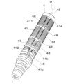
- FIG. 1 is a longitudinal sectional view showing an embodiment of the writing instrument of the present invention.
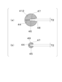
- FIG. 2 is a longitudinal sectional view showing an enlarged main part of FIG. 3(a) is a sectional view taken along the line AA in FIG. 2
- FIG. 3(b) is a sectional view taken along the line BB in FIG. 2
- FIG. 3(c) is a sectional view taken along the line CC in FIG.
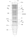
- It is a diagram. 4 is a longitudinal sectional view of the ink reservoir member of FIG. 1.
- FIG. 5(a) is a cross-sectional view taken along line D1-D1 of FIG. 4
- FIG. 5(b) is a cross-sectional view taken along line D2-D2 of FIG.
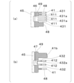
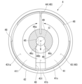
- FIG. 6(a) is a cross-sectional view taken along line E1-E1 of FIG. 4, and FIG. 6(b) is a cross-sectional view taken along line E2-E2 of FIG. 7A is a cross-sectional view taken along line F1-F1 of FIG. 4, and FIG. 7B is a cross-sectional view taken along line F2-F2 of FIG. 8(a) is a cross-sectional view taken along line G1-G1 in FIG. 4, and FIG. 8(b) is a cross-sectional view along line G2-G2 in FIG. 9A is an enlarged view of the H section in FIG. 4, and FIG. 9B is an enlarged view of the I section in FIG. FIG. 10 is a side view of the ink reservoir member of FIG.
- FIG. 11(a) is an enlarged view of part J in FIG. 10
- FIG. 11(b) is an enlarged view of part K in FIG. 12
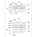
- FIG. 13 is a cross-sectional view taken along line MM of FIG. 10, including an enlarged view of FIG. 6(b).
- FIG. 14 is a cross-sectional view taken along line NN of FIG. 10, and includes an enlarged view of FIG. 8(b).
- FIG. 15 is a cross-sectional view showing the ink reservoir member of the writing instrument of the first modified example of the present embodiment, specifically showing a cross-sectional view corresponding to FIG.
- FIG. 16 is a cross-sectional view showing the ink reservoir member of the writing instrument of the first modified example of the present embodiment, specifically showing a cross-sectional view corresponding to FIG.
- FIG. 17(a) is a side view showing a part of the ink reservoir member of the writing instrument of the second modified example of the present embodiment, and specifically shows a side view corresponding to FIG. 11(a).
- FIG. 17(b) is a side view showing another part of the ink reservoir member of the writing instrument of the second modified example of the present embodiment. Specifically, the side view corresponding to FIG. 11(b) is shown.
- FIG. 18(a) is a cross-sectional view showing a part of the ink reservoir member of the writing instrument of the second modified example of the present embodiment, and specifically shows a vertical cross-sectional view corresponding to FIG. 9(a).
- FIG. 18(b) is a cross-sectional view showing another part of the ink reservoir member of the writing instrument of the second modified example of the present embodiment, and more specifically, a vertical cross-sectional view corresponding to FIG. 9(b). indicates
- FIGS. 1 to 14 A writing instrument 1 according to an embodiment of the present invention is shown in FIGS. 1 to 14.
- FIG. 1 the writing instrument 1 of the present embodiment has a substantially cylindrical shape or a substantially columnar shape centering on the central axis O.
- the writing instrument 1 has a substantially cylindrical shape or a substantially columnar shape.
- illustration of the central axis O may be omitted in arbitrary drawings.
- a writing instrument 1 includes a pen tip 3, an ink reservoir member 4 having the pen tip 3 at its front end, and a shaft having the ink reservoir member 4 provided inside the front portion. It comprises a cylinder 2 , an ink tank 21 provided behind the ink reservoir member 4 inside the shaft cylinder 2 , and an ink guide member 5 provided inside the ink reservoir member 4 .
- the pen tip 3, the ink reservoir member 4, the barrel 2, the ink tank 21, and the ink guide member 5 are coaxially arranged with the central axis O as a common axis.
- the front-rear direction the direction in which the central axis O of the writing instrument 1 extends, that is, the direction along the central axis O is called the front-rear direction.
- the front-rear direction may be referred to as an axial direction or a longitudinal direction.
- the ink tank 21 and the pen tip 3 are arranged at different positions in the front-rear direction (axial direction, longitudinal direction).
- the front side the direction from the ink tank 21 to the pen tip 3
- the rear side the direction from the pen tip 3 to the ink tank 21
- the front side may also be referred to as one side in the axial direction or one side in the longitudinal direction.
- the rear side may also be referred to as the other axial side or the other longitudinal side.
- a direction orthogonal to the central axis O is called a radial direction.
- a direction approaching the central axis O is called radially inward, and a direction away from the central axis O is called radial outward.
- the direction of rotation around the central axis O is called the circumferential direction.
- the pen tip 3 is arranged at the front end of the writing instrument 1 .
- the pen tip 3 extends in the front-rear direction.
- the pen tip 3 is, for example, a ball-point pen tip with a rotatable ball at the front end, a pen body made of fiber or porous material, a metal plate pen body with a slit at the front end like a fountain pen, or an axial and a pen body made of a synthetic resin extruded body having a capillary gap of .
- the pen tip 3 of this embodiment includes a ball-point pen tip 31 and a tip holder 32 that holds the ball-point pen tip 31 .
- a first relay core 31 a is provided inside the ballpoint pen tip 31
- a second relay core 32 a is provided inside the tip holder 32 .
- the rear end of the first relay core 31a and the front end of the second relay core 32a are connected, and the rear end of the second relay core 32a and the front end of the ink guide member 5 are connected.
- the first relay core 31a and the second relay core 32a are members having a capillary gap in the axial direction, and are made of, for example, a synthetic resin extruded body, a fiber processed body, or a porous body.
- the barrel 2 is arranged in a portion of the writing instrument 1 other than the front end portion.
- the shaft cylinder 2 extends in the front-rear direction.
- the barrel 2 is a bottomed cylindrical body with an open front end and a closed rear end, and is obtained by injection molding of a synthetic resin (eg, polypropylene).
- An ink reservoir member 4 is arranged inside the front portion of the barrel 2 .
- An ink tank 21 is formed inside the barrel 2 behind the ink reservoir member 4 . Liquid ink is directly stored in the ink tank 21 .
- the ink is, for example, water-based ink, and has the property of freezing when the temperature drops to a predetermined temperature.
- the ink retention member 4 is arranged between the pen tip 3 and the ink tank 21 in the front-rear direction. Specifically, the ink reservoir member 4 is provided behind the pen tip 3 and in front of the ink tank 21 .
- the ink reservoir member 4 has a substantially tubular shape and extends in the front-rear direction.
- the ink retaining member 4 is a member that can temporarily store and retain the ink overflowing from the ink tank 21 . In this embodiment, the ink overflowing from the ink tank 21 may be referred to as spilled ink.
- the ink reservoir member 4 includes a pen tip holding portion 42 arranged at the front end portion of the ink reservoir member 4, a plurality of substantially disk-shaped comb teeth 41 arranged behind the pen tip holding portion 42, An inner hole 45 formed in the axial center of the ink reservoir member 4 and penetrating the ink reservoir member 4 in the axial direction, a cylindrical portion 49 to which a plurality of comb teeth 41 are connected, and temporarily retaining ink. an ink guide groove 44 communicating with the ink tank 21; an ink reservoir 40; and horizontal holes 46 and 47.
- the ink reservoir member 4 has a plurality of horizontal holes 46,47.
- the plurality of horizontal holes 46 , 47 include a first horizontal hole 46 and a second horizontal hole 47 spaced forward from the first horizontal hole 46 .
- the pen tip 3 is fixed to the pen tip holding portion 42 .
- the pen tip holding portion 42 has a mounting hole communicating with the inner hole 45, and the pen tip 3 is press-fitted into the mounting hole.
- a chip holder 32 holding a ball-point pen chip 31 is press-fitted into the mounting hole.
- the ink guide member 5 is inserted into the inner hole 45 . That is, the ink guide member 5 is provided inside the inner hole 45 .
- the ink reservoir member 4 is an injection-molded body of synthetic resin (eg, ABS resin), in which the comb teeth 41 and the pen tip holding portion 42 are integrally formed.
- the ink retaining member 4 has a function of temporarily retaining surplus ink (overflow ink) from the ink tank 21 when the pressure in the ink tank 21 is increased. Further, the ink retaining member 4 is a member having a function of returning the temporarily retained ink (overflowing ink) to the ink tank 21 when the pressure in the ink tank 21 is lowered.
- the cylindrical portion 49 has a cylindrical shape centered on the central axis O and extends in the front-rear direction. A front end portion of the cylindrical portion 49 is connected to a rear end portion of the pen tip holding portion 42 . The inner hole 45 extends through the tubular portion 49 in the front-rear direction.
- Each of the plurality of comb teeth 41 has a plate shape extending in a direction perpendicular to the central axis O.
- a pair of plate surfaces of each comb tooth 41 faces the front side and the rear side.
- a plurality of comb teeth 41 are formed on the outer surface of the ink reservoir member 4 at intervals in the front-rear direction.
- the comb teeth 41 have a flange shape extending radially outward from the outer peripheral surface of the cylindrical portion 49 . That is, the radially inner end portion of the comb teeth 41 is connected to the outer peripheral surface of the tubular portion 49 .
- the plurality of comb teeth 41 are arranged at suitable intervals in the front-rear direction, and ink retention grooves 43 are formed between the respective comb teeth 41 .
- Each of the plurality of comb teeth 41 is formed with a slit-shaped ink guide groove 44 that extends axially and opens radially outward.
- the ink guide grooves 44 provided in each comb tooth 41 are arranged side by side in the front-rear direction.
- the overall shape of the plurality of ink guide grooves 44 arranged in the front-rear direction may be referred to as (one) ink guide groove 44 .
- the ink guiding grooves 44 are communicated with the respective ink retaining grooves 43 and extend in the axial direction. As shown in FIGS.
- the radial inner end of the ink guide groove 44 is located radially inward of the outer peripheral surface of the cylindrical portion 49 . That is, the ink guide groove 44 penetrates each of the comb teeth 41 in the front-rear direction, is recessed radially inward from the outer peripheral surface of the cylindrical portion 49, and extends in the front-rear direction.
- an ink reservoir portion 40 consisting of an ink reservoir groove 43 and an ink guide groove 44 is formed on the outer surface of the ink reservoir member 4 .
- the ink reservoir 40 is formed on the outer surface of the ink reservoir member 4 in the front-rear direction. Specifically, the ink reservoir 40 is arranged in a portion of the outer surface of the ink reservoir member 4 other than the pen tip holder 42 positioned at the front end. In other words, the ink reservoir 40 is arranged in a portion of the outer surface of the ink reservoir member 4 that is covered by the shaft tube 2 .
- the ink guide groove 44 does not communicate with the inner hole 45 . That is, the ink guide groove 44 is out of communication with the inner hole 45 .
- “non-communication” may have the same meaning as above.
- an air exchange groove 48 is formed at an axially symmetrical position (180 degrees opposite side) from the ink guide groove 44.
- the air exchange groove 48 axially penetrates each comb tooth 41 and opens radially outward.
- the air exchange grooves 48 of the plurality of comb teeth 41 are arranged side by side in the front-rear direction.
- the “axially symmetrical position (180 degrees opposite side)” means that a pair of components (for example, the air exchange groove 48 and the ink guide groove 44 described above) are located 180 degrees from each other around the central axis O. It means that they are arranged at positions that are rotationally symmetrical.
- a substantially disk-shaped rear end flange 41a is formed at the rear end of the group of comb teeth 41 of the ink reservoir member 4.
- the rear end collar portion 41a is in the shape of a flange extending radially outward from the outer peripheral surface of the tubular portion 49 .
- the rear end collar portion 41a has an ink guide groove 44 that communicates with the ink retention groove 43 on the front side and the ink tank 21 on the rear side.
- the ink guide groove 44 of the rear end collar portion 41 a extends axially and opens radially outward, and is not in communication with the inner hole 45 .
- gaps are provided between the outer ends of the plurality of comb teeth 41 and the inner peripheral surface of the barrel 2 so that fluid such as ink and air can flow. Due to the fitting between the outer peripheral surface of the rear end flange portion 41a and the front inner peripheral surface of the barrel 2, the rear end flange portion 41a is contracted and deformed radially inward. Along with this, the width of the ink guide groove 44 of the rear end collar portion 41a, that is, the circumferential dimension, is formed smaller than the groove width of the ink guide grooves 44 of the plurality of comb teeth 41 in front of the rear end collar portion 41a.
- a substantially disk-shaped intermediate brim portion 41b is formed in the intermediate portion of the group of comb teeth 41 of the ink reservoir member 4.
- the intermediate portion of the group of comb teeth 41 specifically refers to the intermediate portion of the group of comb teeth 41 in the front-rear direction. It refers to the part located between the part.
- the intermediate brim portion 41 b has a flange shape extending radially outward from the outer peripheral surface of the cylindrical portion 49 . At least a part of the outer peripheral surface of the intermediate brim portion 41 b is positioned radially outward from the outer end portions of the comb teeth 41 .
- the outer diameter dimension of the intermediate brim portion 41 b is larger than the outer diameter dimension of each comb tooth 41 .
- the intermediate collar portion 41b includes an ink guide groove 44 and two air exchange grooves 48 formed on both sides of the ink guide groove 44 in the circumferential direction so as to straddle the ink guide groove 44.
- the ink guide groove 44 is axially penetrated through the intermediate collar portion 41b, is open radially outward, and is not in communication with the inner hole 45.
- the two air exchange grooves 48 are provided axially through the intermediate collar portion 41b and open radially outward.
- the two air exchange grooves 48 of the intermediate collar portion 41b are different in position in the circumferential direction from the air exchange grooves 48 of each comb tooth 41 .
- the outer surface of the intermediate collar portion 41b is fitted to the inner surface of the barrel 2. As shown in FIG.
- a substantially disk-shaped front end flange 41c is formed at the front end of the group of comb teeth 41 of the ink reservoir member 4. As shown in FIG. At least a portion of the outer peripheral surface of the front end collar portion 41 c is positioned radially outward from the outer end portions of the comb teeth 41 . In this embodiment, the outer diameter dimension of the front end collar portion 41 c is larger than the outer diameter dimension of each comb tooth 41 .
- An air exchange groove 48 is formed in the front end collar portion 41c so as to penetrate in the axial direction and open radially outward.
- the air exchange grooves 48 of the front end collar portion 41c are formed on the same side as the air exchange grooves 48 of the comb teeth 41 other than the intermediate collar portion 41b. Specifically, the air exchange grooves 48 of the front end collar portion 41c and the air exchange grooves 48 of the comb teeth 41 overlap each other when viewed in the front-rear direction.
- the air exchange grooves 48 of the front end collar portion 41c and the air exchange grooves 48 of the comb teeth 41 are located at the same position in the circumferential direction.
- the ink guide groove 44 is not formed in the front end collar portion 41c.
- the ink guide member 5 is a member that has a capillary gap in the axial direction and guides the ink from the ink tank 21 to the pen tip 3 . That is, the ink guide member 5 supplies ink from the ink tank 21 to the pen tip 3 .
- the ink guide member 5 is made of, for example, a synthetic resin extruded body, a fiber processed body, or a porous body.
- the ink guide member 5 connects the inside of the ink tank 21 and the pen tip 3 .
- the ink guide member 5 may be constructed of a single member or may be constructed of a plurality of members.
- the ink guide member 5 may protrude rearward into the ink tank 21 .
- the ink guide member 5 may protrude rearward from the rear end surface of the ink reservoir member 4 , and a part (rear end portion) thereof may be disposed inside the ink tank 21 . Also, a separate ink guide member connected to the ink guide member 5 in the inner hole 45 may be arranged in the ink tank 21 .
- the outer surface of the ink reservoir member 4 is provided with a first horizontal hole 46 which opens radially outward and communicates with the inner hole 45. It is formed.
- the first horizontal hole 46 radially penetrates at least the peripheral wall of the cylindrical portion 49 .
- the first horizontal hole 46 is formed axially symmetrical with the ink guide groove 44 (that is, on the opposite side by 180 degrees).
- the first horizontal hole 46 and the ink guide groove 44 are formed so as not to communicate with each other in cross section.
- the first horizontal hole 46 is formed in the rear half of the ink reservoir 40.
- the longitudinal distance L1 from the rear end of the ink reservoir 40 to the rear end of the first horizontal hole 46 is set within a range of 5% to 45% of the total longitudinal dimension L of the ink reservoir 40. be done.
- the overall length L corresponds to the longitudinal distance from the front end of the ink guide groove 44 to the rear end of the ink guide groove 44 .
- the distance L1 is preferably set in the range of 15% to 30% of the total hand dimension L.
- the first horizontal hole 46 extends in the longitudinal direction from the rear end of the ink reservoir 40 to the rear end of the first horizontal hole 46. is set in the range of 1.5 mm to 13.5 mm (preferably 4.5 mm to 9 mm).
- the rear half of the ink reservoir 40 refers to the rear of the midpoint of the overall length L of the ink reservoir 40 .
- the rear half of the ink reservoir 40 refers to a portion of the ink reservoir 40 located behind the center (midpoint) in the front-rear direction.
- the first horizontal hole 46 is axially aligned with a plurality of (specifically, three) comb teeth 411 arranged axially. and is open radially outwardly.
- the first horizontal hole 46 communicates with a plurality of (specifically, four) ink retaining grooves 431, 431a adjacent to each other in front and behind each comb tooth 411 in which the first horizontal hole 46 is formed.
- the shape of the opening of the first horizontal hole 46 has a rectangular shape when the first horizontal hole 46 is viewed from the outside in the radial direction, as shown in FIG. 11(a).
- the opening of the first horizontal hole 46 has, for example, a length S1 in the longitudinal direction of 1 mm to 2 mm and a length T1 in the width direction (anti-longitudinal direction) of 1 mm to 2 mm.
- the width direction may be rephrased as the lateral direction or the circumferential direction.
- the lengths S1 and T1 correspond to the opening dimensions of a portion of the first horizontal hole 46 that opens into the inner hole 45 (first inner opening 46a, which will be described later).
- the length S1 in the longitudinal direction of the opening of the first horizontal hole 46 is the plate thickness of the three comb teeth 411 forming the first horizontal hole 46 and the thickness of the three comb teeth 411. It is the sum of the groove widths (axial dimensions) of the two ink reservoir grooves 431a.
- the area of the opening of the first horizontal hole 46 is set to 1 mm 2 to 4 mm 2 , for example.
- the widthwise length T1 of the opening of the first horizontal hole 46 is set, for example, in the range of 60% to 85% (preferably 65% to 80%) of the inner diameter of the inner hole 45 .
- the shape of the opening of the first horizontal hole 46 may be other quadrangular shapes such as a circular shape, an elliptical shape, a square shape, or a polygonal shape other than the quadrangular shape, in addition to the rectangular shape.
- the first horizontal hole 46 may be configured so as to penetrate at least one comb tooth 411 in the axial direction and open radially outward. Also, the first horizontal hole 46 may be configured to communicate with the ink retention grooves 431 and 431a adjacent to the front or rear of at least one comb tooth 411 having the first horizontal hole 46 . Preferably, the first horizontal hole 46 communicates with a plurality of ink retention grooves 431, 431a adjacent to the front and rear of at least one comb tooth 411 having the first horizontal hole 46. . That is, the first horizontal hole 46 axially penetrates through at least one comb tooth 411 (41) and communicates with the ink retention grooves 431, 431a (43) adjacent to the comb tooth 411. As shown in FIG.
- the radial depth of the ink reservoir groove 43 gradually becomes shallower toward the rear.
- a shallow trench region 43a is formed.
- the area of the inner wall of the ink guiding groove 44 near the ink tank 21 is increased, and smooth ink circulation with the ink tank 21 is made possible.
- a first horizontal hole 46 is formed in front of the shallow groove region 43a of the ink reservoir groove 43.
- each of the comb teeth 41, 411, 412 is formed with an air exchange groove 48 penetrating in the axial direction.
- the air exchange grooves 48 are formed in the portions of the comb teeth 41, 411, 412 excluding the ink guide grooves 44 (specifically, the axially symmetrical positions of the ink guide grooves 44).
- the first horizontal hole 46 communicates with the air exchange groove 48 in the radial direction.
- the air exchange grooves 48 radially communicating with the first horizontal holes 46 are formed in the comb teeth 41 adjacent to the comb teeth 411 having the first horizontal holes 46 . It is formed at the same position in the circumferential direction as the air exchange groove 48 (i.e., axially symmetrical with the ink guide groove 44). This makes it easy to manufacture the mold for molding the ink reservoir member 4 .
- the outer surface of the ink reservoir member 4 in front of the first horizontal hole 46 communicates with the inner hole 45 and extends radially outward.
- An open second lateral hole 47 is formed.
- the second horizontal hole 47 radially penetrates at least the peripheral wall of the cylindrical portion 49 .
- the second horizontal hole 47 is formed axially symmetrical with the ink guide groove 44 (that is, on the opposite side by 180 degrees).
- the second horizontal hole 47 and the ink guide groove 44 are formed so as not to communicate with each other in cross section.
- the second horizontal hole 47 communicates with the air exchange groove 48 in the radial direction.
- the air exchange groove 48 radially communicating with the second horizontal hole 47 is formed in the comb tooth 41 adjacent to the comb tooth 412 having the second horizontal hole 47. It is formed at the same position in the circumferential direction as the air exchange groove 48 (i.e., axially symmetrical with the ink guide groove 44). This makes it easy to manufacture the mold for molding the ink reservoir member 4 .
- the second horizontal hole 47 is formed in the front half of the ink reservoir 40 .
- the longitudinal distance L2 from the rear end of the first horizontal hole 46 to the rear end of the second horizontal hole 47 is 30% or more (preferably 40% or more) of the total length L of the ink reservoir 40. set.
- the front half of the ink reservoir 40 refers to the front of the midpoint of the overall length L of the ink reservoir 40 .
- the front half of the ink reservoir 40 refers to a portion of the ink reservoir 40 located forward of the center (midpoint) in the front-rear direction.
- the second horizontal hole 47 is axially aligned with a plurality of (specifically, two) comb teeth 412 arranged in the axial direction. and is open radially outwardly.
- the second horizontal hole 47 communicates with a plurality (specifically, three) of ink retaining grooves 432, 432a adjacent to each other in front and behind each comb tooth 412 in which the second horizontal hole 47 is formed.
- the shape of the opening of the second horizontal hole 47 has a rectangular shape when the second horizontal hole 47 is viewed from the outside in the radial direction.
- the opening of the second horizontal hole 47 has a length S2 of 1 mm to 2 mm in the longitudinal direction and a length T2 of 1 mm to 2 mm in the width direction (anti-longitudinal direction), for example.
- the lengths S2 and T2 correspond to the opening dimensions of a portion of the second horizontal hole 47 that opens into the inner hole 45 (second inner opening 47a to be described later).
- the length S2 in the longitudinal direction of the opening of the second horizontal hole 47 is 1.5 times the thickness of the two comb teeth 412 forming the second horizontal hole 47 and the thickness of the two comb teeth 412 .
- the longitudinal length S2 of the opening of the second horizontal hole 47 is formed larger than the groove width of the ink reservoir groove 432a in which the second horizontal hole 47 is formed.
- the area of the opening of the second horizontal hole 47 is set to 1 mm 2 to 4 mm 2 , for example.
- the widthwise length T2 of the opening of the second horizontal hole 47 is set, for example, in the range of 60% to 85% (preferably 65% to 80%) of the inner diameter of the inner hole 45 .
- the shape of the opening of the second horizontal hole 47 may be other quadrangular shapes such as a circular shape, an elliptical shape, a square shape, or a polygonal shape other than the quadrangular shape, in addition to the rectangular shape.
- the second horizontal hole 47 may be configured to axially penetrate through at least one comb tooth 412 and open radially outward. Also, the second horizontal hole 47 may be configured to communicate with the ink reservoir grooves 432 and 432a adjacent to the front or rear of at least one comb tooth 412 having the second horizontal hole 47 . Preferably, the second horizontal hole 47 communicates with a plurality of ink retention grooves 432, 432a adjacent to the front and rear of at least one comb tooth 412 having the second horizontal hole 47. . That is, the second horizontal hole 47 is axially penetrated through at least one comb tooth 412 (41) and communicates with the ink retaining grooves 432, 432a (43) adjacent to the comb tooth 412. As shown in FIG.
- the horizontal holes 46 and 47 include inner openings 46a and 47a opening into the inner hole 45, outer openings 46b and 47b opening radially outward, Stepped portions 46c and 47c arranged between the inner opening portions 46a and 47a and the outer opening portions 46b and 47b and directed radially outward.
- the first horizontal hole 46 has a first inner opening 46a that opens into the inner hole 45 and a first outer opening 46b that opens radially outward. , and a first stepped portion 46c disposed between the first inner opening 46a and the first outer opening 46b and facing radially outward.
- the first inner opening 46 a is arranged at the radially inner end of the first horizontal hole 46 and connected to the inner hole 45 .
- the first outer opening 46b is arranged radially outside the first inner opening 46a and communicates with the air exchange groove 48 and the ink retention grooves 431, 431a.
- the widthwise (circumferential) dimension of the first outer opening 46b is larger than the widthwise dimension (length T1) of the first inner opening 46a.
- the longitudinal dimension (front-rear direction) of the first outer opening 46b is the same as the longitudinal dimension (length S1) of the first inner opening 46a.
- the first stepped portion 46c connects the first inner opening 46a and the first outer opening 46b.
- a pair of first stepped portions 46c are provided at both ends in the width direction (circumferential direction) of the inner wall of the first horizontal hole 46 .
- the pair of first stepped portions 46c are arranged on a pair of long sides of the four sides of the rectangular opening of the first horizontal hole 46 and extend in the axial direction (see FIG. 11A).
- Each of the pair of first stepped portions 46c has a planar shape extending in a direction perpendicular to the predetermined radial direction in which the first horizontal hole 46 extends.
- the pair of first stepped portions 46c are flat surfaces that are inclined with respect to the predetermined radial direction and extend outward in the radial direction as they separate from each other in the width direction.
- the pair of first stepped portions 46c may have planar shapes that are inclined with respect to the predetermined radial direction and extend radially inward as they are separated from each other in the width direction.
- the first stepped portion 46c is not limited to a planar shape, and may have a convex curved surface shape, a concave curved surface shape, or the like.
- the second horizontal hole 47 includes a second inner opening 47a that opens into the inner hole 45, a second outer opening 47b that opens radially outward, and a second lateral opening 47b. and a second stepped portion 47c disposed between the inner opening portion 47a and the second outer opening portion 47b and facing radially outward.
- the second inner opening 47 a is arranged at the radially inner end of the second horizontal hole 47 and connected to the inner hole 45 .
- the second outer opening 47b is arranged radially outward of the second inner opening 47a and communicates with the air exchange groove 48 and the ink retention grooves 432, 432a.
- the dimension in the width direction (circumferential direction) of the second outer opening 47b is larger than the dimension in the width direction (length T2) of the second inner opening 47a.
- the longitudinal dimension (front-rear direction) of the second outer opening 47b is the same as the longitudinal dimension (length S2) of the second inner opening 47a.
- the second stepped portion 47c connects the second inner opening 47a and the second outer opening 47b.
- a pair of second stepped portions 47c are provided at both ends in the width direction (circumferential direction) of the inner wall of the second horizontal hole 47 .
- the pair of second stepped portions 47c are arranged on a pair of long sides of the four sides of the second horizontal hole 47 having a rectangular opening shape and extend in the axial direction (see FIG. 11B).
- Each of the pair of second stepped portions 47c has a planar shape extending in a direction perpendicular to the predetermined radial direction in which the second horizontal hole 47 extends.
- the pair of second stepped portions 47c are flat surfaces that are inclined with respect to the predetermined radial direction and extend outward in the radial direction as they separate from each other in the width direction.
- the pair of second stepped portions 47c may have planar shapes that are inclined with respect to the predetermined radial direction and extend radially inward as they are separated from each other in the width direction.
- the second stepped portion 47c is not limited to a planar shape, and may have a convex curved surface shape, a concave curved surface shape, or the like.
- the writing instrument 1 of the present embodiment includes the pen tip 3, the ink tank 21 for directly storing ink, and the pen tip 3 provided at the front end and in front of the ink tank 21. , an ink reservoir member 4 for temporarily holding spilled ink due to an increase in pressure in the ink tank 21; and an ink guide member 5, wherein the ink reservoir member 4 includes a plurality of plate-like comb teeth 41 formed on the outer surface at intervals, and the comb teeth 41 A plurality of ink retaining grooves 43 for temporarily retaining ink formed therebetween, and axially extending slit-like grooves communicating with the ink tank 21 and each of the ink retaining grooves 43 .
- the ink reservoir member 4 includes a first horizontal hole 46 that opens radially outward and communicates with the internal hole 45, and the first horizontal hole 46 communicates with the internal hole 45.
- 46 and the ink guide groove 44 are formed non-communicatingly in the cross section, and the first horizontal hole 46 is provided in the rear half of the ink reservoir 40.
- the writing instrument 1 can freeze the ink pushed out from the ink tank 21 before it reaches the vicinity of the pen tip 3.
- the ink can be quickly and reliably discharged from the first horizontal hole 46 near the ink tank 21 to the outside (ink reservoir 40).
- the ink reservoir member 4 is disposed in front of the first horizontal hole 46 and has a second horizontal hole that opens radially outward and communicates with the inner hole 45 . 47, and the second horizontal hole 47 and the ink guide groove 44 are formed non-communicatingly in the cross section.
- the writing instrument 1 of the present embodiment when the ink is frozen, the amount of volumetric expansion of the frozen ink in the ink tank 21 is discharged to the outside mainly through the first horizontal hole 46, and is discharged through the second horizontal hole.
- the volume expansion of the frozen ink inside the inner hole 45 is discharged to the outside through 47 .
- the ink in the ink tank 21 is first discharged to the pen tip 3 (that is, at the time of initial ink discharge)
- the residual air inside the inner hole 45 is discharged through the second horizontal hole 47.
- the ink can be reliably discharged from the ink tank 21 to the outside, and the ink can be rapidly led out to the pen tip 3 from the ink tank 21.
- the writing instrument 1 of the present embodiment may be configured to have only the first horizontal hole 46 , but it is preferable to provide the second horizontal hole 47 .
- the first horizontal hole 46 is axially penetrated through at least one comb tooth 411 and communicates with the ink retaining grooves 431 and 431 a adjacent to the comb tooth 411 .
- the first horizontal hole 46 axially penetrates the plurality of comb teeth 411 and communicates with the plurality of ink retention grooves 431 and 431a adjacent to the front and back of each of the comb teeth 411. be.
- the writing instrument 1 of the present embodiment can secure a sufficient opening area for the first horizontal hole 46, and when the ink freezes, the overflowing ink from the first horizontal hole 46 can be reliably discharged to the outside. Furthermore, the writing instrument 1 of the present embodiment discharges the overflowing ink from the first horizontal hole 46 to the ink retaining grooves 431, 431a (specifically, the plurality of ink retaining grooves 431, 431a) when the ink is frozen. can do.
- the second horizontal hole 47 is axially penetrated through at least one comb tooth 412 and communicates with the ink retaining grooves 432 and 432 a adjacent to the comb tooth 412 .
- the second horizontal hole 47 axially penetrates the plurality of comb teeth 412 and communicates with a plurality of ink retention grooves 432, 432a adjacent to the front and rear of each of the comb teeth 412. be.
- the writing instrument 1 of the present embodiment can secure a sufficient opening area for the second horizontal hole 47, and when the ink freezes, the overflowing ink from the second horizontal hole 47 can be reliably discharged to the outside. Furthermore, the writing instrument 1 of the present embodiment discharges the overflowing ink from the second horizontal hole 47 to the ink retaining grooves 432, 432a (specifically, the plurality of ink retaining grooves 432, 432a) when the ink is frozen. can do.
- the first horizontal hole 46 and the second horizontal hole 47 are axially penetrating through at least one comb tooth 41 and adjacent to the comb tooth 41 . It communicates with the reservoir groove 43 .
- the overflowing ink inside the inner hole 45 can be reliably discharged to the outside. can be avoided.
- the first horizontal hole 46 includes a first inner opening 46a that opens into the inner hole 45 and a first outer opening 46b that opens radially outward. and a first step portion 46c arranged between the first inner opening portion 46a and the first outer opening portion 46b and directed radially outward.
- the ink discharged from the inner hole 45 to the outside through the first horizontal hole 46 is prevented from being returned to the inside of the inner hole 45 by the first step portion 46c. be able to.
- the second horizontal hole 47 includes a second inner opening 47a that opens into the inner hole 45 and a second outer opening 47b that opens radially outward. and a second stepped portion 47c arranged between the second inner opening portion 47a and the second outer opening portion 47b and directed radially outward.
- the ink discharged from the inner hole 45 to the outside through the second horizontal hole 47 is prevented from being returned to the inside of the inner hole 45 by the second step portion 47c. be able to.
- the writing instrument 1 of the present embodiment includes a pen tip 3, an ink tank 21 for directly storing ink, and the pen tip 3 at the front end thereof and provided in front of the ink tank 21. and an ink guide member 5 provided inside the ink reservoir member 4 for supplying the ink from the ink tank 21 to the pen tip 3.
- the ink reservoir member 4 includes a plurality of plate-shaped comb teeth 41 formed on the outer surface at intervals, and formed between the comb teeth 41, a plurality of ink retaining grooves 43 for temporarily retaining ink; axially extending slit-like ink guiding grooves 44 communicating with the ink tank 21 and each of the ink retaining grooves 43; an inner hole 45 extending axially through which the ink guide member 5 is provided; the ink reservoir member 4 is a horizontal hole that opens radially outward and communicates with the inner hole 45; (the first horizontal hole 46 and/or the second horizontal hole 47), the horizontal holes 46, 47 and the ink guide groove 44 are formed in a non-communicating manner in the cross section, and the horizontal holes 46, 47 are A writing instrument 1 characterized in that it is axially penetrating through at least one comb tooth 41 and communicates with an ink retaining groove 43 adjacent to the comb tooth 41 . Specifically, the horizontal holes 46 and 47 are axially penetrated
- the writing instrument 1 of the present embodiment can secure a sufficient opening area for the horizontal holes 46 and 47, and can reliably discharge the ink overflowing from the horizontal holes 46 and 47 to the outside when the ink is frozen. Furthermore, when the ink is frozen, the writing instrument 1 of the present embodiment can discharge ink overflowing from the lateral holes 46 and 47 to the ink retaining grooves 43 (specifically, a plurality of ink retaining grooves 43). As a result, when the pressure in the ink tank 21 is reduced after the ink is thawed, the ink in the ink retention groove 43 is rapidly collected in the ink tank 21 through the ink guide groove 44. - ⁇ As a result, ink residue in the vicinity of the lateral holes 46 and 47 can be avoided.
- the number of lateral holes 46 and 47 provided and the position of the lateral holes 47 are not limited to the form described above. That is, the number and positions of the horizontal holes 46 and 47 axially penetrating through at least one comb tooth 41 and communicating with the ink retaining groove 43 adjacent to the comb tooth 41 are different from those of the present embodiment. Not limited. For example, a configuration in which two lateral holes are provided in the front and rear portions, a configuration in which only one lateral hole is provided in the rear half of the ink reservoir 40, and only one lateral hole is provided in the central portion of the ink reservoir 40. , or a configuration in which only one horizontal hole is provided in the front half of the ink reservoir portion 40, or the like.
- the horizontal holes 46 and 47 have inner openings 46a and 47a opening into the inner hole 45 and outer openings 46b and 47b opening radially outward. , and stepped portions 46c, 47c disposed between the inner openings 46a, 47a and the outer openings 46b, 47b and facing radially outward.
- the writing instrument 1 of the present embodiment includes a pen tip 3, an ink tank 21 for directly storing ink, the pen tip 3 provided at the front end portion and in front of the ink tank 21, and the ink tank an ink reservoir member 4 for temporarily holding ink overflowing due to an increase in pressure in the ink reservoir 21; and a guide member 5, wherein the ink reservoir member 4 includes a plurality of plate-like comb teeth 41 formed on the outer surface at intervals from each other and between the comb teeth 41.
- a plurality of ink retaining grooves 43 formed to temporarily retain ink, and axially extending slit-shaped ink guides communicating with the ink tank 21 and communicating with each of the ink retaining grooves 43.
- Communicating horizontal holes (first horizontal hole 46 and/or second horizontal hole 47) are provided.
- 46 and 47 are composed of inner openings 46a and 47a opening into the inner hole 45, outer openings 46b and 47b opening radially outward, the inner openings 46a and 47a and the outer openings 46a and 47b.
- the writing instrument 1 is characterized by having stepped portions 46c and 47c arranged between the side openings 46b and 47b and facing radially outward.
- the ink discharged from the inner hole 45 to the outside through the lateral holes 46 and 47 is prevented from being returned to the inside of the inner hole 45 by the stepped portions 46c and 47c. can be done. According to this embodiment, it is possible to prevent the ink from leaking from the nib 3 due to unintentional return of the spilled ink from the lateral holes 46 and 47 to the inner hole 45 .
- the overflowed ink discharged from the lateral holes 46 and 47 can be efficiently returned to the ink tank 21 . Therefore, it is possible to solve the above another problem.
- FIG. 15 is a cross-sectional view showing the ink reservoir member 4 of the writing instrument 1 of the first modified example, specifically showing a cross-sectional view corresponding to FIG. 16 is a cross-sectional view showing the ink reservoir member 4 of the writing instrument 1 of the first modified example, and specifically shows a cross-sectional view corresponding to FIG. 14.
- FIG. 14 shows that in the drawings of the respective modifications described below, the same reference numerals are given to the same configurations as in the above-described embodiment, and mainly different points will be described below.
- the radially inner end of the first stepped portion 46c of the first horizontal hole 46 is connected to the inner peripheral surface of the inner hole 45, as shown in FIG. Therefore, the first inner opening 46a is located at the ridge line where the inner peripheral surface of the inner hole 45 and the first stepped portion 46c are connected. Further, as shown in FIG. 16 , the radially inner end of the second stepped portion 47 c of the second horizontal hole 47 is connected to the inner peripheral surface of the inner hole 45 . Therefore, the second inner opening 47a is positioned at the ridge line where the inner peripheral surface of the inner hole 45 and the second stepped portion 47c are connected.
- FIG. 17(a) is a side view showing a part of the ink reservoir member 4 of the writing instrument 1 of the second modified example, specifically showing a side view corresponding to FIG. 11(a).
- FIG. 17(b) is a side view showing a part of the ink reservoir member 4 of the writing instrument 1 of the second modified example, specifically showing a side view corresponding to FIG. 11(b).
- FIG. 18(a) is a cross-sectional view showing a part of the ink reservoir member 4 of the writing instrument 1 of the second modified example, and specifically shows a vertical cross-sectional view corresponding to FIG. 9(a).
- FIG. 18(b) is a cross-sectional view showing a part of the ink reservoir member 4 of the writing instrument 1 of the second modified example, and specifically shows a vertical cross-sectional view corresponding to FIG. 9(b).
- the first step portion 46c of the first horizontal hole 46 is the width direction of the inner wall of the first horizontal hole 46.
- a pair are provided at both ends in the circumferential direction and a pair are provided at both ends in the axial direction (front-rear direction).
- the four first stepped portions 46c are arranged on all four sides of the first horizontal hole 46 having a rectangular opening shape.
- the second step portion 47c of the second horizontal hole 47 is formed in the width direction (circumferential direction) of the inner wall of the second horizontal hole 47.
- a pair at both end portions and a pair at both end portions in the axial direction (front-rear direction) are provided for a total of four.
- the four second stepped portions 47c are arranged on all four sides of the second horizontal hole 47 having a rectangular opening shape.
- the present invention may combine the configurations described in the above-described embodiments and modifications without departing from the gist of the present invention, and addition, omission, replacement, and other modifications of the configuration are possible. be. Moreover, the present invention is not limited by the above-described embodiments and the like, but is limited only by the scope of the claims.
- the writing instrument of the present invention even if the ink inside freezes, it is possible to reliably prevent ink leakage from the nib. Therefore, it has industrial applicability.
Landscapes
- Engineering & Computer Science (AREA)
- Mechanical Engineering (AREA)
- Pens And Brushes (AREA)
Priority Applications (5)
| Application Number | Priority Date | Filing Date | Title |
|---|---|---|---|
| EP22904180.1A EP4446123A1 (en) | 2021-12-08 | 2022-12-05 | Writing implement |
| KR1020247020629A KR20240112896A (ko) | 2021-12-08 | 2022-12-05 | 필기구 |
| US18/716,302 US20250033402A1 (en) | 2021-12-08 | 2022-12-05 | Writing implement |
| JP2023566304A JPWO2023106251A1 (en, 2012) | 2021-12-08 | 2022-12-05 | |
| CN202280081318.XA CN118369216A (zh) | 2021-12-08 | 2022-12-05 | 书写工具 |
Applications Claiming Priority (2)
| Application Number | Priority Date | Filing Date | Title |
|---|---|---|---|
| JP2021-198947 | 2021-12-08 | ||
| JP2021198947 | 2021-12-08 |
Publications (1)
| Publication Number | Publication Date |
|---|---|
| WO2023106251A1 true WO2023106251A1 (ja) | 2023-06-15 |
Family
ID=86730350
Family Applications (1)
| Application Number | Title | Priority Date | Filing Date |
|---|---|---|---|
| PCT/JP2022/044669 WO2023106251A1 (ja) | 2021-12-08 | 2022-12-05 | 筆記具 |
Country Status (7)
| Country | Link |
|---|---|
| US (1) | US20250033402A1 (en, 2012) |
| EP (1) | EP4446123A1 (en, 2012) |
| JP (1) | JPWO2023106251A1 (en, 2012) |
| KR (1) | KR20240112896A (en, 2012) |
| CN (1) | CN118369216A (en, 2012) |
| TW (1) | TW202339984A (en, 2012) |
| WO (1) | WO2023106251A1 (en, 2012) |
Citations (5)
| Publication number | Priority date | Publication date | Assignee | Title |
|---|---|---|---|---|
| JPS59190584U (ja) * | 1983-06-02 | 1984-12-18 | 三菱鉛筆株式会社 | 筆記具に於けるインク保溜体 |
| JPS63108784U (en, 2012) * | 1986-12-29 | 1988-07-13 | ||
| JPH0273371U (en, 2012) * | 1988-07-30 | 1990-06-05 | ||
| JP4212714B2 (ja) | 1998-03-26 | 2009-01-21 | 三菱鉛筆株式会社 | インク保溜体を備えた筆記具 |
| JP4666872B2 (ja) | 2000-05-18 | 2011-04-06 | 三菱鉛筆株式会社 | コレクター式筆記具 |
Family Cites Families (5)
| Publication number | Priority date | Publication date | Assignee | Title |
|---|---|---|---|---|
| KR960002247B1 (ko) * | 1988-07-30 | 1996-02-14 | 펜텔 가부시기가이샤 | 일시 잉크저장부재와 이것을 사용한 필기도구 |
| DE4243686C2 (de) * | 1992-12-18 | 1996-12-12 | Rotring Int Gmbh | Tinten- oder Tuscheschreibgerät |
| JP6309813B2 (ja) * | 2013-05-21 | 2018-04-11 | 三菱鉛筆株式会社 | コレクター式塗布具 |
| CN105848918B (zh) * | 2013-10-21 | 2017-09-05 | 有限会社V斯帕克 | 压力变动缓冲机构以及涂敷具 |
| JP7100904B2 (ja) * | 2020-01-17 | 2022-07-14 | ケミコスクリエイションズ株式会社 | 直液式ペン型アイライナー |
-
2022
- 2022-12-05 KR KR1020247020629A patent/KR20240112896A/ko active Pending
- 2022-12-05 WO PCT/JP2022/044669 patent/WO2023106251A1/ja active Application Filing
- 2022-12-05 CN CN202280081318.XA patent/CN118369216A/zh active Pending
- 2022-12-05 EP EP22904180.1A patent/EP4446123A1/en active Pending
- 2022-12-05 US US18/716,302 patent/US20250033402A1/en active Pending
- 2022-12-05 JP JP2023566304A patent/JPWO2023106251A1/ja active Pending
- 2022-12-05 TW TW111146548A patent/TW202339984A/zh unknown
Patent Citations (5)
| Publication number | Priority date | Publication date | Assignee | Title |
|---|---|---|---|---|
| JPS59190584U (ja) * | 1983-06-02 | 1984-12-18 | 三菱鉛筆株式会社 | 筆記具に於けるインク保溜体 |
| JPS63108784U (en, 2012) * | 1986-12-29 | 1988-07-13 | ||
| JPH0273371U (en, 2012) * | 1988-07-30 | 1990-06-05 | ||
| JP4212714B2 (ja) | 1998-03-26 | 2009-01-21 | 三菱鉛筆株式会社 | インク保溜体を備えた筆記具 |
| JP4666872B2 (ja) | 2000-05-18 | 2011-04-06 | 三菱鉛筆株式会社 | コレクター式筆記具 |
Also Published As
| Publication number | Publication date |
|---|---|
| KR20240112896A (ko) | 2024-07-19 |
| TW202339984A (zh) | 2023-10-16 |
| JPWO2023106251A1 (en, 2012) | 2023-06-15 |
| CN118369216A (zh) | 2024-07-19 |
| EP4446123A1 (en) | 2024-10-16 |
| US20250033402A1 (en) | 2025-01-30 |
Similar Documents
| Publication | Publication Date | Title |
|---|---|---|
| KR102390052B1 (ko) | 펜 및 펜용 리필 | |
| US9688092B2 (en) | Refill for writing tool and writing tool | |
| US8128304B2 (en) | Direct-fluid-supply writing implement | |
| JP6283349B2 (ja) | 筆記具及びインキカートリッジ | |
| HK1250503A1 (en) | Refill for writing tool and writing tool | |
| US7938592B2 (en) | Writing implement | |
| US6276860B1 (en) | Liquid applicator | |
| WO2023106251A1 (ja) | 筆記具 | |
| JP4820701B2 (ja) | 直液式筆記具 | |
| US6341914B2 (en) | Ballpoint pen tip and ballpoint pen using the same | |
| US20020181997A1 (en) | Writing implement | |
| JP4658259B2 (ja) | 直液式筆記具 | |
| JP4537864B2 (ja) | 直液式筆記具 | |
| JP2005313404A (ja) | 筆記具 | |
| JP4511381B2 (ja) | 直液式筆記具 | |
| JP2020001352A (ja) | ボールペン | |
| JP7118814B2 (ja) | ボールペン | |
| JP5961009B2 (ja) | 直液式筆記具 | |
| JP4080280B2 (ja) | 直液式筆記具 | |
| JP3056959U (ja) | インク・ペン | |
| JP2004330710A (ja) | 液体容器 | |
| JP2012131196A (ja) | ペン先 | |
| HK1212656B (zh) | 笔具以及墨水芯 |
Legal Events
| Date | Code | Title | Description |
|---|---|---|---|
| 121 | Ep: the epo has been informed by wipo that ep was designated in this application |
Ref document number: 22904180 Country of ref document: EP Kind code of ref document: A1 |
|
| WWE | Wipo information: entry into national phase |
Ref document number: 18716302 Country of ref document: US |
|
| WWE | Wipo information: entry into national phase |
Ref document number: 2023566304 Country of ref document: JP |
|
| WWE | Wipo information: entry into national phase |
Ref document number: 202280081318.X Country of ref document: CN Ref document number: P2024-01449 Country of ref document: AE |
|
| WWE | Wipo information: entry into national phase |
Ref document number: 202417046586 Country of ref document: IN |
|
| ENP | Entry into the national phase |
Ref document number: 20247020629 Country of ref document: KR Kind code of ref document: A |
|
| WWE | Wipo information: entry into national phase |
Ref document number: 1020247020629 Country of ref document: KR |
|
| WWE | Wipo information: entry into national phase |
Ref document number: 2022904180 Country of ref document: EP |
|
| NENP | Non-entry into the national phase |
Ref country code: DE |
|
| ENP | Entry into the national phase |
Ref document number: 2022904180 Country of ref document: EP Effective date: 20240708 |