WO2023105836A1 - 光ケーブル構造及び光ケーブル構造の製造方法 - Google Patents
光ケーブル構造及び光ケーブル構造の製造方法 Download PDFInfo
- Publication number
- WO2023105836A1 WO2023105836A1 PCT/JP2022/025859 JP2022025859W WO2023105836A1 WO 2023105836 A1 WO2023105836 A1 WO 2023105836A1 JP 2022025859 W JP2022025859 W JP 2022025859W WO 2023105836 A1 WO2023105836 A1 WO 2023105836A1
- Authority
- WO
- WIPO (PCT)
- Prior art keywords
- optical
- optical fiber
- optical fibers
- connector
- distal
- Prior art date
- Legal status (The legal status is an assumption and is not a legal conclusion. Google has not performed a legal analysis and makes no representation as to the accuracy of the status listed.)
- Ceased
Links
Images




Classifications
-
- G—PHYSICS
- G02—OPTICS
- G02B—OPTICAL ELEMENTS, SYSTEMS OR APPARATUS
- G02B6/00—Light guides; Structural details of arrangements comprising light guides and other optical elements, e.g. couplings
- G02B6/44—Mechanical structures for providing tensile strength and external protection for fibres, e.g. optical transmission cables
- G02B6/4401—Optical cables
- G02B6/4429—Means specially adapted for strengthening or protecting the cables
- G02B6/443—Protective covering
-
- G—PHYSICS
- G02—OPTICS
- G02B—OPTICAL ELEMENTS, SYSTEMS OR APPARATUS
- G02B6/00—Light guides; Structural details of arrangements comprising light guides and other optical elements, e.g. couplings
- G02B6/46—Processes or apparatus adapted for installing or repairing optical fibres or optical cables
- G02B6/50—Underground or underwater installation; Installation through tubing, conduits or ducts
- G02B6/54—Underground or underwater installation; Installation through tubing, conduits or ducts using mechanical means, e.g. pulling or pushing devices
- G02B6/545—Pulling eyes
-
- G—PHYSICS
- G02—OPTICS
- G02B—OPTICAL ELEMENTS, SYSTEMS OR APPARATUS
- G02B6/00—Light guides; Structural details of arrangements comprising light guides and other optical elements, e.g. couplings
- G02B6/44—Mechanical structures for providing tensile strength and external protection for fibres, e.g. optical transmission cables
- G02B6/4479—Manufacturing methods of optical cables
- G02B6/4486—Protective covering
-
- G—PHYSICS
- G02—OPTICS
- G02B—OPTICAL ELEMENTS, SYSTEMS OR APPARATUS
- G02B6/00—Light guides; Structural details of arrangements comprising light guides and other optical elements, e.g. couplings
- G02B6/02—Optical fibres with cladding with or without a coating
- G02B6/02042—Multicore optical fibres
-
- G—PHYSICS
- G02—OPTICS
- G02B—OPTICAL ELEMENTS, SYSTEMS OR APPARATUS
- G02B6/00—Light guides; Structural details of arrangements comprising light guides and other optical elements, e.g. couplings
- G02B6/24—Coupling light guides
- G02B6/255—Splicing of light guides, e.g. by fusion or bonding
- G02B6/2551—Splicing of light guides, e.g. by fusion or bonding using thermal methods, e.g. fusion welding by arc discharge, laser beam, plasma torch
-
- G—PHYSICS
- G02—OPTICS
- G02B—OPTICAL ELEMENTS, SYSTEMS OR APPARATUS
- G02B6/00—Light guides; Structural details of arrangements comprising light guides and other optical elements, e.g. couplings
- G02B6/24—Coupling light guides
- G02B6/36—Mechanical coupling means
- G02B6/38—Mechanical coupling means having fibre to fibre mating means
- G02B6/3807—Dismountable connectors, i.e. comprising plugs
- G02B6/3873—Connectors using guide surfaces for aligning ferrule ends, e.g. tubes, sleeves, V-grooves, rods, pins, balls
- G02B6/3885—Multicore or multichannel optical connectors, i.e. one single ferrule containing more than one fibre, e.g. ribbon type
Definitions
- the present invention relates to an optical cable structure and a method for manufacturing an optical cable structure.
- the tip portion of the optical cable is housed in a tubular member (pulling end) for protection.
- a plurality of optical fibers, each having an optical connector terminated at each tip may be housed inside the tubular member as the tip portion of the optical cable.
- the lengths of a plurality of optical fibers constituting the tip portion of an optical cable are varied, and a plurality of optical connectors terminated to the plurality of optical fibers are shifted in the length direction of the optical fiber (optical cable).
- An arranged optical cable structure is disclosed.
- the plurality of optical connectors can be prevented from becoming bulky in the radial direction of the optical cable, and the diameter of the tubular member that accommodates the plurality of optical connectors can be kept small. Therefore, even if the number of optical fibers having optical connectors at their distal ends is large, the optical cables can be passed through a thin duct.
- the present invention has been made in view of the circumstances described above, and is an optical cable that allows easy termination of an optical connector for a plurality of optical fibers forming the distal end portion of the optical cable housed in a tubular member. It is an object of the present invention to provide a structure and method of manufacturing an optical cable structure.
- An optical cable structure is an optical cable structure having a plurality of optical fibers with connectors led out from an end of a sheath of the optical cable and housed in a tubular member having a predetermined length,
- Each optical fiber with a connector includes a lead-out optical fiber led out from the end of the sheath, and an optical connector provided at the leading end of the lead-out optical fiber in the lead-out direction. At least some of the lead-out optical fibers led out from the end of the sheath have different lengths.
- the plurality of lead-out optical fibers include a proximal side optical fiber positioned on the end side of the sheath, a distal side optical fiber positioned on the optical connector side, the proximal side optical fiber and the distal side optical fiber. and a connecting portion for connecting to the fiber.
- the connecting portions of the plurality of lead-out optical fibers are positioned inside the tubular member.
- a method for manufacturing an optical cable structure according to one aspect of the present invention is a method for manufacturing an optical cable structure having a plurality of optical fibers with connectors led out from the end of a sheath of the optical cable and housed in a tubular member having a predetermined length.
- the lengths of the plurality of tip-side optical fibers are adjusted so that the lengths of at least some of the plurality of lead-out optical fibers led out from the end of the sheath are different. At least one of the length and the length of the plurality of base end optical fibers is set.
- the present invention it is possible to easily perform the termination work of the optical connector for the plurality of lead-out optical fibers that constitute the tip portion of the optical cable and are accommodated in the tubular member.
- FIG. 1 is a cross-sectional view showing an optical cable structure according to a first embodiment of the present invention and a state in which a plurality of optical fibers with connectors constituting the structure are housed in a tubular member;
- FIG. 2 is a perspective view showing a state in which a plurality of optical fibers with connectors are taken out from a tubular member in FIG. 1;
- FIG. 3 is an enlarged perspective view showing the optical fiber with connector of FIGS. 1 and 2;
- 4 is a cross-sectional view taken along line IV-IV of FIG. 3;
- FIG. 4 is a cross-sectional view taken along line VV of FIG. 3;
- FIG. 4 is a cross-sectional view taken along the line VI-VI of FIG. 3; 4 is an exploded perspective view of the optical fiber with connector of FIG. 3; FIG. FIG. 4 is a diagram showing the manufacturing process of the optical cable structure according to the first embodiment of the present invention;
- FIG. 6 is a cross-sectional view showing an optical cable structure according to a second embodiment of the present invention and a state in which a plurality of optical fibers with connectors constituting the optical cable structure are housed in a tubular member;
- 10 is an enlarged plan view showing the optical fiber with connector of FIG. 9;
- FIG. FIG. 11 is a perspective view showing a state in which the optical fiber with connector of FIG. 10 is separated into a proximal side optical fiber, a distal side optical fiber, and a fusion splicing portion;
- FIG. 5 is a diagram showing the manufacturing process of the optical cable structure according to the second embodiment of the present invention;
- FIG. 1 the optical cable structure of the first embodiment has a plurality of connectorized optical fibers 1 that are led out from the end of the sheath S of the optical cable C and constitute the tip portion of the optical cable C.
- the number of optical fibers 1 with connectors in the illustrated example is three, the number is not limited to this.
- a plurality of optical fibers 1 with connectors are accommodated in a tubular member 100 having a predetermined length.
- the tubular member 100 covers a plurality of optical fibers 1 with connectors.
- the tubular member 100 has a role of protecting the plurality of connectorized optical fibers 1 when the optical cable C is passed through a building duct or the like.
- the tubular member 100 also serves as a pulling end that is pulled when the optical cable C is passed through the duct or the like.
- the tubular member 100 is removed from the optical cable C after passing the optical cable C through a duct or the like.
- Tubular member 100 has a tubular body 101 and a head 102 .
- the tubular main body 101 is formed in a tubular shape to accommodate the optical fiber 1 with connector.
- Tubular body 101 may be flexible, for example.
- the head 102 is provided at the distal end of the tubular body 101 and covers the opening on the distal end side of the tubular body 101 .
- a pooling eye 103 is provided at the tip of the head 102 . By tying a rope or the like to the pulling eye 103 and pulling it, the optical cable C can be easily passed through a duct or the like.
- the tubular member 100 accommodates a plurality of connector-equipped optical fibers 1 in a tubular main body 101, and holds the proximal end of the tubular main body 101 with a holder 105 fixed to the end of the sheath S by a screw or the like. , is detachably attached to the optical cable C.
- each connector-equipped optical fiber 1 of the optical cable C includes a lead-out optical fiber 2 led out from the end of the sheath S and a leading end of the lead-out optical fiber 2 in the lead-out direction. and an optical connector 3 .
- the lead-out optical fiber 2 has cores 52, 62 (see FIGS. 4 to 6) for transmitting optical signals.
- the number of cores 52 and 62 in the lead-out optical fiber 2 may be, for example, one, but is plural in this embodiment.
- the lead-out optical fiber 2 has a proximal side optical fiber 5, a distal side optical fiber 6, and a connecting portion 7.
- the proximal side optical fiber 5 is a portion on the proximal side of the lead-out optical fiber 2 located on the end side of the sheath S.
- the proximal end optical fiber 5 in this embodiment is a multi-core fiber 51 having a plurality of (seven in the illustrated example) cores 52 .
- a plurality of cores 52 constituting the multi-core fiber 51 are arranged on the same circumference around the axis C1 of the proximal optical fiber 5 when viewed from the longitudinal direction of the proximal optical fiber 5, and are spaced apart around the axis C1. are lined up.
- one core 52 is arranged on the axis C1 of the proximal end optical fiber 5 .
- the tip-side optical fiber 6 is a part on the tip side of the lead-out optical fiber 2 located on the optical connector 3 side.
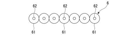
- the distal optical fiber 6 in this embodiment is composed of a plurality of (seven in the illustrated example) single-core fibers 61 each having one core 62 .
- the number of single-core fibers 61 forming the distal optical fiber 6 corresponds to the number of cores 52 (see FIG. 4) of the multi-core fiber 51 forming the proximal optical fiber 5 .
- FIG. 3 at the proximal end (second end) 6B in the longitudinal direction of the distal optical fiber 6 located on the proximal optical fiber 5 side, as shown in FIG. 61 are arranged so as to correspond to the arrangement of the plurality of cores 52 of the proximal end optical fiber 5 shown in FIG. Specifically, as shown in FIG. 5, at the proximal end of the distal end side optical fiber 6, a plurality of single core fibers 61 are arranged on the same circumference around a predetermined axis C2. Also, one single core fiber 61 is arranged so as to be positioned on a predetermined axis C2.
- FIG. 3 at the tip (first end) 6A in the longitudinal direction of the tip-side optical fiber 6 positioned on the optical connector 3 side, as shown in FIG. They are arranged so as to correspond to the optical connector 3 (ferrule). Specifically, as shown in FIG. 6, a plurality of single-core fibers 61 are arranged in a line at the tip of the tip-side optical fiber 6 in a straight line direction (horizontal direction in FIG. 6) perpendicular to its longitudinal direction.
- the connecting portion 7 connects the proximal side optical fiber 5 and the distal side optical fiber 6 .
- the connecting portion 7 has a role of optically coupling the plurality of cores 52 (see FIG. 4) of the proximal side optical fiber 5 and the plurality of cores 62 (see FIG. 5) of the distal side optical fiber 6 individually.
- the connecting portion 7 of this embodiment is a connector connecting portion 71 that mechanically connects the proximal side optical fiber 5 and the distal side optical fiber 6 .
- the connector connecting portion 71 has a proximal side connector 72 , a distal side connector 73 and an adapter 74 .
- the proximal side connector 72 is provided at the distal end portion of the proximal side optical fiber 5 and has a connection surface 721 from which the distal end of the proximal side optical fiber 5 is exposed.
- an insertion hole is formed in the base end connector 72 . The distal end of the proximal-side optical fiber 5 is inserted through this insertion hole and exposed from the connection surface 721 of the proximal-side connector 72 .
- the distal connector 73 is provided at the proximal end of the distal optical fiber 6 and has a connection surface 731 from which the proximal end of the distal optical fiber 6 is exposed. Although not shown, an insertion hole is formed in the distal connector 73 . The proximal end of the distal optical fiber 6 is inserted through this insertion hole and exposed from the connection surface 731 of the distal connector 73 .
- the adapter 74 connects the proximal side connector 72 and the distal side connector 73 to connect the core 52 (see FIG. 4) of the proximal side optical fiber 5 and the core 62 (see FIG. 5) of the distal side optical fiber 6. optically couple.
- the adapter 74 of this embodiment is formed in a tubular shape with both ends in the axial direction open.
- the proximal side connector 72 and the distal side connector 73 are inserted into the openings at both ends of the adapter 74 so that the connection surfaces 721 and 731 of the proximal side connector 72 and the distal side connector 73 face each other.
- the connecting surfaces 721 and 731 of the proximal side connector 72 and the distal side connector 73 are brought into contact with each other, and the core 52 of the proximal side optical fiber 5 and the core 62 of the distal side optical fiber 6 are optically coupled. can be done.
- the lengths of the plurality of lead-out optical fibers 2 lead out from the end of the sheath S are different.
- all lead-out optical fibers 2 have different lengths.
- the lengths of the plurality of base end-side optical fibers 5 constituting the plurality of lead-out optical fibers 2 are different.
- the lengths of the plurality of tip-side optical fibers 6 constituting the plurality of lead-out optical fibers 2 are equal.
- the plurality of connection portions 7 located at the respective distal end portions of the plurality of proximal-side optical fibers 5
- the part 71) is offset in the lead-out direction of the lead-out optical fiber 2 .
- the optical connector 3 is provided at the tip of each lead-out optical fiber 2 in the lead-out direction, that is, at the tip of each tip-side optical fiber 6 .
- the optical connector 3 has a connection end face 31 where the tip of the tip end optical fiber 6 is exposed.
- the optical connector 3 is formed with an insertion hole. The tip of the tip-side optical fiber 6 is inserted through this insertion hole and exposed from the connection end face 31 of the optical connector 3 .
- the insertion hole of the optical connector 3 is arranged such that a plurality of single-core fibers 61 (see FIG. 6) forming the distal end-side optical fiber 6 are arranged in a line in a straight line direction orthogonal to the longitudinal direction thereof.
- the connecting portions 7 of all lead-out optical fibers 2 are positioned inside the tubular member 100.
- the length of all connectorized optical fibers 1 is shorter than the length of the tubular member 100 .
- the optical connector 3 is terminated to the first end (tip) 6A in the longitudinal direction of the tip-side optical fiber 6 (first step ).
- the terminating work of the optical connector 3 in the first step includes the insertion work of inserting the tip end side optical fiber 6 into the optical connector 3, the connection end face 31 of the optical connector 3 and the tip end side optical fiber 6 exposed at this connection end face 31.
- a polishing work for polishing the tip and an inspection work for inspecting the optical loss at the tip of the tip end side optical fiber 6 exposed at the connection end face 31 are included.
- the distal end connector 73 is terminated to the second end portion (base end portion) 6B of the distal end optical fiber 6 .
- the termination work of the distal connector 73 may include insertion work, polishing work, and inspection work similar to the termination work of the optical connector 3 described above.
- a first step is performed for a plurality of distal optical fibers 6 .
- the lengths of the plurality of tip-side optical fibers 6 are set in advance so that the lengths of the plurality of tip-side optical fibers 6 are equal.
- a plurality of base end side optical fibers 5 are led out from the end of the sheath S of the optical cable C (second step).
- the lengths of the plurality of proximal side optical fibers 5 are set so that the plurality of proximal side optical fibers 5 have different lengths.
- the proximal end connector 72 is terminated to the distal end portion of the proximal end optical fiber 5 .
- the termination operation of the proximal connector 72 may include insertion, polishing, and inspection operations similar to those described above.
- the second step may be performed, for example, before or after the first step, or simultaneously with the first step.
- the lead-out optical fiber 2 having the base-side optical fiber 5 and the distal-side optical fiber 6 is constructed. Further, an optical fiber 1 with a connector extending from the end of the sheath S and having a lead-out optical fiber 2 and an optical connector 3 is constructed.
- the proximal side optical fiber 5 and the distal side optical fiber 6 are connected by the connector connecting portion 71 .
- the adapter 74 is used to connect the proximal connector 72 provided at the distal end of the proximal optical fiber 5 and the second end (base end) 6B of the distal optical fiber 6.
- the proximal side optical fiber 5 and the distal side optical fiber 6 are connected by abutting the distal side connector 73 that has been provided.
- the lengths of the plurality of tip-side optical fibers 6 are set so that the lengths of the plurality of tip-side optical fibers 6 are equal.
- the lengths of the plurality of proximal side optical fibers 5 are set so that the plurality of proximal side optical fibers 5 have different lengths. Therefore, in the state after the third step, the plurality of lead-out optical fibers 2 have different lengths. The above completes the manufacturing method of the optical cable structure.
- the lengths of the plurality of lead-out optical fibers 2 lead out from the end of the sheath S are different. Therefore, the plurality of optical connectors 3 provided at the tip portions of the plurality of lead-out optical fibers 2 can be shifted in the lead-out direction of the lead-out optical fibers 2 . Thereby, it is possible to prevent the plurality of optical connectors 3 from being bulky in the radial direction of the optical cable C. FIG. Therefore, it is possible to accommodate a plurality of optical fibers 1 with connectors in the tubular member 100 having a small diameter.
- the distal end side optical fiber 6 is It can be connected to fiber 5 . That is, before connecting the distal optical fiber 6 to the proximal optical fiber 5, the optical connector 3 can be terminated. Therefore, even if the lengths of the lead-out optical fibers 2 in the optical cable structure after manufacture are different, the termination operation of the optical connector 3 for the lead-out optical fibers 2 accommodated in the tubular member 100 can be easily performed. can be done.
- the termination work (especially polishing work) of the optical connector 3 to the tip-side optical fibers 6 and inspection work) can be easily performed.
- the lengths of the plurality of proximal side optical fibers 5 extending from the end of the sheath S are different. Therefore, the plurality of connecting portions 7 provided at the distal end portions of the plurality of base-end-side optical fibers 5 can be shifted in the longitudinal direction of the lead-out optical fiber 2 . Thereby, it is possible to prevent the plurality of connecting portions 7 from being bulky in the radial direction of the optical cable C. As shown in FIG. Therefore, it is possible to easily accommodate a plurality of optical fibers 1 with connectors in the tubular member 100 having a small diameter. In the first embodiment, since the diameter of the connector connection portion 71 is larger than the diameter of the lead-out optical fiber 2, the above effect is particularly useful.
- the lengths of the plurality of front end optical fibers 6 are equal.
- an optical cable structure can be manufactured using a plurality of tip-side optical fibers 6 having the same length. Therefore, it is possible to efficiently manufacture the optical cable structure.
- the proximal side optical fiber 5 and the distal side optical fiber 6 are mechanically connected by the connector connecting portion 71 . This makes it possible to easily connect the proximal side optical fiber 5 and the distal side optical fiber 6 without using a device such as a fusion splicer.
- the optical cable structure of the second embodiment includes a plurality of optical fibers 1B with connectors led out from the end of the sheath S of the optical cable C and accommodated in the tubular member 100, as in the first embodiment.
- the lead-out optical fiber 2B of each connector-equipped optical fiber 1B has a connection portion 7B that connects the proximal-side optical fiber 5 and the distal-side optical fiber 6 .
- the splicing portion 7B of the second embodiment is a fusion splicing portion 71B that splices the proximal side optical fiber 5 and the distal side optical fiber 6 by fusion splicing.
- the fusion splicer 71B of the second embodiment is constructed separately from the proximal side optical fiber 5 and the distal side optical fiber 6.
- FIG. 10 to 11 the fusion splicer 71B of the second embodiment is constructed separately from the proximal side optical fiber 5 and the distal side optical fiber 6.
- the fusion splicing portion 71B has a proximal side portion 72B and a distal side portion 73B.
- the base end portion 72B is composed of a multi-core fiber having multiple cores.
- the cross-sectional shape of the proximal side portion 72B is the same as the cross-sectional shape of the proximal side optical fiber 5 shown in FIG.
- the distal portion 73B is composed of a plurality of single-core fibers having one core.
- the cross-sectional shape of the tip-side portion 73B is the same as the cross-sectional shape of the proximal end portion side of the tip-side optical fiber 6 shown in FIG.
- the proximal side portion 72B and the distal side portion 73B are arranged in the longitudinal direction of these cores (horizontal direction in FIG. 10) and joined by fusion or the like. Thereby, the plurality of cores of the proximal side portion 72B and the plurality of cores of the distal side portion 73B are optically coupled individually.
- an optical connector for example, an MT ferrule
- the rotation direction of the optical fiber optical fiber
- the end of the optical fiber is a single-core fiber, the rotational directionality of the optical fiber is lost, so the above alignment work is not necessary.
- the proximal end portion 72B of the fusion splicing portion 71B is fusion spliced to the distal end portion of the proximal end optical fiber 5 .
- the tip end portion 73B of the fusion splicing portion 71B is fusion spliced to the base end portion of the tip end optical fiber 6 .
- the core 52 (see FIG. 4) of the proximal side optical fiber 5 and the core 62 (see FIG. 5) of the distal side optical fiber 6 are connected to each other by the fusion splicing portion 71B (the proximal side portion 72B and the distal side portion 73B). ) are optically coupled through the core of
- the length of the fusion splicing portion 71B is shorter than the lengths of the proximal side optical fiber 5 and the distal side optical fiber 6 .
- the length of the fusion splicing portion 71B is the same among the plurality of lead-out optical fibers 2B.
- the fusion splicing portion 71B may have a protective sleeve that protects the fusion spliced portions with the proximal side optical fiber 5 and the distal side optical fiber 6, for example.
- the diameter dimension of the fusion splicing portion 71B is larger than the diameter dimension of the derived optical fiber 2 .
- the distal end side optical fiber 6 is not terminated with the distal side connector 73 (see FIGS. 7 and 8) in the first step, and the proximal side optical fiber 5 is terminated in the second step. It differs from the manufacturing method of the first embodiment in that the base-end connector 72 (see FIGS. 7 and 8) is not terminated.
- the second ends (base ends) 6B of the plurality of distal side optical fibers 6 are connected to the distal ends of the plurality of proximal side optical fibers 5, respectively. The method of doing is different from the manufacturing method of the first embodiment.
- the third step in the manufacturing method of the second embodiment will be described below.
- the distal end portion of the proximal side optical fiber 5 and the proximal end portion of the distal side optical fiber 6 are fusion spliced by the fusion splicing portion 71B. do. Specifically, first, as shown in FIGS. 11 and 12, a fusion splicing portion 71B is arranged between the distal end portion of the proximal side optical fiber 5 and the proximal end portion of the distal side optical fiber 6. FIG. After that, as shown in FIG. 10, the tip of the proximal end optical fiber 5 is fusion spliced to the proximal end portion 72B of the fusion splicing portion 71B.
- the proximal end portion of the distal end side optical fiber 6 is fusion spliced to the distal end portion 73B of the fusion splicing portion 71B.
- the manufacturing method of the second embodiment is completed by performing the third step of the second embodiment described above after the first step and the second step.
- the same effects as those of the first embodiment are obtained. Further, according to the second embodiment, the proximal side optical fiber 5 and the distal side optical fiber 6 are fusion-spliced. Thereby, the proximal side optical fiber 5 and the distal side optical fiber 6 can be connected with higher reliability.
- the fusion splicing portion 71B is configured separately from the proximal side optical fiber 5 and the distal side optical fiber 6 .
- the fusion splicing portion 71B includes a proximal portion 72B composed of a multi-core fiber similar to the proximal optical fiber 5 and a distal portion 72B composed of a plurality of single core fibers similar to the distal optical fiber 6. and a portion 73B. Therefore, the proximal side optical fiber 5 and the distal side optical fiber 6 can be connected by fusion splicing between multi-core fibers and fusion splicing between a plurality of single core fibers.
- fusion splicing between optical fibers of the same type can be performed more easily than fusion splicing between optical fibers of different types (that is, fusion splicing between a multi-core fiber and a plurality of single-core fibers).
- fusion splicing between optical fibers of different types that is, fusion splicing between a multi-core fiber and a plurality of single-core fibers.
- a large number of fusion splicing portions 71B having the proximal side portion 72B and the distal side portion 73B should be manufactured in advance. can be done. This makes it possible to efficiently perform fusion splicing between the plurality of proximal side optical fibers 5 and the plurality of distal side optical fibers 6 . From the above, it is possible to efficiently manufacture the optical cable structure.
- the length of the fusion splicing portion 71B may differ among the plurality of lead-out optical fibers 2B.
- the lengths of the plurality of lead-out optical fibers 2B may be varied by varying the lengths of the fusion splicing portions 71B among the plurality of lead-out optical fibers 2B.
- the length of the fusion splicing portion 71B may be equal to or longer than the lengths of the proximal side optical fiber 5 and the distal side optical fiber 6, for example.
- the fusion splicing portion 71B may be composed of, for example, the tip portion of the proximal side optical fiber 5 and the proximal portion of the distal side optical fiber 6. That is, the proximal side optical fiber 5 and the distal side optical fiber 6 may be directly fusion-spliced.
- the lengths of the plurality of proximal end optical fibers 5 may be equal.
- the lengths of the leading optical fibers 2 and 2B may be varied by varying the lengths of the distal optical fibers 6, for example.
- both the proximal side optical fiber 5 and the distal side optical fiber 6 may be, for example, a multi-core fiber 51, or may be composed of a plurality of single-core fibers 61, for example. Also, the proximal side optical fiber 5 and the distal side optical fiber 6 may be one single core fiber 61 .
- the lengths of the plurality of tip-side optical fibers 6 may be set so that the lengths of the plurality of tip-side optical fibers 6 are different.
- the lengths of the plurality of proximal side optical fibers 5 may be set such that the lengths of the plurality of proximal side optical fibers 5 are different, as in the above embodiment.
- the lengths of the plurality of proximal side optical fibers 5 may be set so that the lengths of the plurality of proximal side optical fibers 5 are equal.
- the lengths of the plurality of distal side optical fibers 6 and the plurality of proximal side optical fibers 5 can be set in this way, the lengths of the plurality of lead-out optical fibers 2 and 2B in the optical cable structure after manufacture can be made different.
- the lengths of all lead-out optical fibers 2, 2B extending from the end of the sheath S do not have to be different.
- some of the lead-out optical fibers 2, 2B may have the same length.
- the plurality of lead-out optical fibers 2, 2B extending from the end of the sheath S are divided into a plurality of groups, the lengths of the plurality of lead-out optical fibers 2, 2B constituting the same group are made the same, and different groups are led out.
- the optical fibers 2, 2B may have different lengths.
- the plurality of optical connectors 3 provided at the tips of the plurality of lead-out optical fibers 2, 2B forming the same group are arranged at the same position in the lead-out direction of the lead-out optical fibers 2, 2B. Also, the optical connectors 3 provided at the tips of the lead-out optical fibers 2 and 2B of different groups are shifted in the lead-out direction of the lead-out optical fibers 2 and 2B.
Landscapes
- Physics & Mathematics (AREA)
- General Physics & Mathematics (AREA)
- Optics & Photonics (AREA)
- Engineering & Computer Science (AREA)
- Plasma & Fusion (AREA)
- Manufacturing & Machinery (AREA)
- Mechanical Coupling Of Light Guides (AREA)
Priority Applications (3)
| Application Number | Priority Date | Filing Date | Title |
|---|---|---|---|
| US18/706,601 US20250012992A1 (en) | 2021-12-08 | 2022-06-29 | Optical cable structure and optical cable structure production method |
| CN202280069661.2A CN118140167A (zh) | 2021-12-08 | 2022-06-29 | 光缆构造及光缆构造的制造方法 |
| JP2023566082A JP7637795B2 (ja) | 2021-12-08 | 2022-06-29 | 光ケーブル構造及び光ケーブル構造の製造方法 |
Applications Claiming Priority (2)
| Application Number | Priority Date | Filing Date | Title |
|---|---|---|---|
| JP2021199309 | 2021-12-08 | ||
| JP2021-199309 | 2021-12-08 |
Publications (1)
| Publication Number | Publication Date |
|---|---|
| WO2023105836A1 true WO2023105836A1 (ja) | 2023-06-15 |
Family
ID=86730071
Family Applications (1)
| Application Number | Title | Priority Date | Filing Date |
|---|---|---|---|
| PCT/JP2022/025859 Ceased WO2023105836A1 (ja) | 2021-12-08 | 2022-06-29 | 光ケーブル構造及び光ケーブル構造の製造方法 |
Country Status (4)
| Country | Link |
|---|---|
| US (1) | US20250012992A1 (https=) |
| JP (1) | JP7637795B2 (https=) |
| CN (1) | CN118140167A (https=) |
| WO (1) | WO2023105836A1 (https=) |
Cited By (1)
| Publication number | Priority date | Publication date | Assignee | Title |
|---|---|---|---|---|
| JP2022132153A (ja) * | 2021-02-26 | 2022-09-07 | ティーイー コネクティビティ サービシーズ ゲーエムベーハー | ケーブルアセンブリ |
Citations (6)
| Publication number | Priority date | Publication date | Assignee | Title |
|---|---|---|---|---|
| WO2012121318A1 (ja) * | 2011-03-09 | 2012-09-13 | 古河電気工業株式会社 | 光コネクタ、マルチコアファイバとバンドル構造との調芯方法、ファイバ配列変換部材 |
| JP2015166818A (ja) * | 2014-03-04 | 2015-09-24 | 住友電気工業株式会社 | 光ファイバ用配列変換アダプタ |
| JP2015166757A (ja) * | 2014-03-03 | 2015-09-24 | 住友電気工業株式会社 | 光ファイバ用配列変換アダプタ |
| US20160041356A1 (en) * | 2013-04-07 | 2016-02-11 | Tyco Electronics (Shanghai) Co., Ltd. | Fiber optic connection assembly |
| US20190004273A1 (en) * | 2017-06-28 | 2019-01-03 | Corning Research & Development Corporation | High fiber count pre-terminated optical distribution assembly |
| WO2021199736A1 (ja) * | 2020-04-02 | 2021-10-07 | 株式会社フジクラ | 収容構造体、牽引端付き光ケーブル及び収容構造体の製造方法 |
-
2022
- 2022-06-29 US US18/706,601 patent/US20250012992A1/en active Pending
- 2022-06-29 WO PCT/JP2022/025859 patent/WO2023105836A1/ja not_active Ceased
- 2022-06-29 CN CN202280069661.2A patent/CN118140167A/zh active Pending
- 2022-06-29 JP JP2023566082A patent/JP7637795B2/ja active Active
Patent Citations (6)
| Publication number | Priority date | Publication date | Assignee | Title |
|---|---|---|---|---|
| WO2012121318A1 (ja) * | 2011-03-09 | 2012-09-13 | 古河電気工業株式会社 | 光コネクタ、マルチコアファイバとバンドル構造との調芯方法、ファイバ配列変換部材 |
| US20160041356A1 (en) * | 2013-04-07 | 2016-02-11 | Tyco Electronics (Shanghai) Co., Ltd. | Fiber optic connection assembly |
| JP2015166757A (ja) * | 2014-03-03 | 2015-09-24 | 住友電気工業株式会社 | 光ファイバ用配列変換アダプタ |
| JP2015166818A (ja) * | 2014-03-04 | 2015-09-24 | 住友電気工業株式会社 | 光ファイバ用配列変換アダプタ |
| US20190004273A1 (en) * | 2017-06-28 | 2019-01-03 | Corning Research & Development Corporation | High fiber count pre-terminated optical distribution assembly |
| WO2021199736A1 (ja) * | 2020-04-02 | 2021-10-07 | 株式会社フジクラ | 収容構造体、牽引端付き光ケーブル及び収容構造体の製造方法 |
Cited By (1)
| Publication number | Priority date | Publication date | Assignee | Title |
|---|---|---|---|---|
| JP2022132153A (ja) * | 2021-02-26 | 2022-09-07 | ティーイー コネクティビティ サービシーズ ゲーエムベーハー | ケーブルアセンブリ |
Also Published As
| Publication number | Publication date |
|---|---|
| CN118140167A (zh) | 2024-06-04 |
| JP7637795B2 (ja) | 2025-02-28 |
| US20250012992A1 (en) | 2025-01-09 |
| JPWO2023105836A1 (https=) | 2023-06-15 |
Similar Documents
| Publication | Publication Date | Title |
|---|---|---|
| JP5798177B2 (ja) | マルチコア光ファイバケーブルのための単心コネクタ | |
| JP5759183B2 (ja) | 光コネクタ及びその組立方法 | |
| CN110178063B (zh) | 光纤保持部件、光连接器及光耦合构造 | |
| US10578812B2 (en) | Methods for forming connectorized fiber optic cabling | |
| US8834042B2 (en) | Quick terminated fiber optic termini and fiber optic cable, and method for making | |
| US9110253B2 (en) | Optical connector and method for assembling optical connector | |
| JP7637795B2 (ja) | 光ケーブル構造及び光ケーブル構造の製造方法 | |
| JP7595655B2 (ja) | フォトニック・チップの一次元辺縁部のための2列フェルール・リボン用インターレース・ブーツ | |
| WO2020189772A1 (ja) | 間欠連結型光ファイバテープ心線、光ファイバケーブルおよびコネクタ付き光ファイバコード | |
| CN108431657A (zh) | 用于保持光纤电缆中的选定顺序的光纤束组件 | |
| JP2003329887A (ja) | 多心光ファイバテープ心線付き光コネクタ及び多心光ファイバコード付き光コネクタ | |
| JP4141684B2 (ja) | コネクタ付き光ファイバコード及びコネクタ付き光ファイバケーブル | |
| JP7845195B2 (ja) | コネクタ付きケーブル | |
| CN100592121C (zh) | 光缆、用于光缆的连接系统以及用于连接多个光波导的组件 | |
| JPWO2023105836A5 (https=) | ||
| JP2024106759A (ja) | 光ファイババンドル、光接続構造、及び光ファイババンドルの製造方法 | |
| WO2026074849A1 (ja) | 光ファイバケーブル | |
| JPH01262506A (ja) | 多心光ファイバケーブルの永久接続装置およびその接続方法 | |
| JP2006011254A (ja) | 光コネクタ部品及び該光コネクタ部品付きボード及び該ボードを有した光伝送機器 | |
| US20220163746A1 (en) | Optical fiber connector device | |
| CN118409386A (zh) | 光纤束的制造方法、光纤束、光连接结构及判定方法 | |
| GB2622374A (en) | Optical fibre connector | |
| JP3103834U (ja) | 多心光ファイバ線用コネクタ | |
| JPH0626887Y2 (ja) | 多心―多心光ファイバ接続部 | |
| WO2020144935A1 (ja) | ファンアウトコードおよびその製造方法 |
Legal Events
| Date | Code | Title | Description |
|---|---|---|---|
| 121 | Ep: the epo has been informed by wipo that ep was designated in this application |
Ref document number: 22903772 Country of ref document: EP Kind code of ref document: A1 |
|
| WWE | Wipo information: entry into national phase |
Ref document number: 2023566082 Country of ref document: JP |
|
| WWE | Wipo information: entry into national phase |
Ref document number: 202280069661.2 Country of ref document: CN |
|
| WWE | Wipo information: entry into national phase |
Ref document number: 18706601 Country of ref document: US |
|
| NENP | Non-entry into the national phase |
Ref country code: DE |
|
| 122 | Ep: pct application non-entry in european phase |
Ref document number: 22903772 Country of ref document: EP Kind code of ref document: A1 |