WO2023105836A1 - 光ケーブル構造及び光ケーブル構造の製造方法 - Google Patents
光ケーブル構造及び光ケーブル構造の製造方法 Download PDFInfo
- Publication number
- WO2023105836A1 WO2023105836A1 PCT/JP2022/025859 JP2022025859W WO2023105836A1 WO 2023105836 A1 WO2023105836 A1 WO 2023105836A1 JP 2022025859 W JP2022025859 W JP 2022025859W WO 2023105836 A1 WO2023105836 A1 WO 2023105836A1
- Authority
- WO
- WIPO (PCT)
- Prior art keywords
- optical
- optical fiber
- optical fibers
- connector
- distal
- Prior art date
Links
- 230000003287 optical effect Effects 0.000 title claims abstract description 125
- 238000004519 manufacturing process Methods 0.000 title claims description 33
- 239000013307 optical fiber Substances 0.000 claims abstract description 300
- 239000000835 fiber Substances 0.000 claims description 34
- 238000007526 fusion splicing Methods 0.000 claims description 31
- 238000000034 method Methods 0.000 claims description 9
- 238000003780 insertion Methods 0.000 description 10
- 230000037431 insertion Effects 0.000 description 10
- 230000004927 fusion Effects 0.000 description 9
- 238000005498 polishing Methods 0.000 description 5
- 238000007689 inspection Methods 0.000 description 4
- 238000010586 diagram Methods 0.000 description 2
- 230000000694 effects Effects 0.000 description 2
- 238000005452 bending Methods 0.000 description 1
- 230000008878 coupling Effects 0.000 description 1
- 238000010168 coupling process Methods 0.000 description 1
- 238000005859 coupling reaction Methods 0.000 description 1
- 238000012986 modification Methods 0.000 description 1
- 230000004048 modification Effects 0.000 description 1
- 238000011176 pooling Methods 0.000 description 1
- 230000001681 protective effect Effects 0.000 description 1
Images


Classifications
-
- G—PHYSICS
- G02—OPTICS
- G02B—OPTICAL ELEMENTS, SYSTEMS OR APPARATUS
- G02B6/00—Light guides; Structural details of arrangements comprising light guides and other optical elements, e.g. couplings
- G02B6/02—Optical fibres with cladding with or without a coating
-
- G—PHYSICS
- G02—OPTICS
- G02B—OPTICAL ELEMENTS, SYSTEMS OR APPARATUS
- G02B6/00—Light guides; Structural details of arrangements comprising light guides and other optical elements, e.g. couplings
- G02B6/24—Coupling light guides
- G02B6/255—Splicing of light guides, e.g. by fusion or bonding
-
- G—PHYSICS
- G02—OPTICS
- G02B—OPTICAL ELEMENTS, SYSTEMS OR APPARATUS
- G02B6/00—Light guides; Structural details of arrangements comprising light guides and other optical elements, e.g. couplings
- G02B6/24—Coupling light guides
- G02B6/36—Mechanical coupling means
-
- G—PHYSICS
- G02—OPTICS
- G02B—OPTICAL ELEMENTS, SYSTEMS OR APPARATUS
- G02B6/00—Light guides; Structural details of arrangements comprising light guides and other optical elements, e.g. couplings
- G02B6/44—Mechanical structures for providing tensile strength and external protection for fibres, e.g. optical transmission cables
Definitions
- the present invention relates to an optical cable structure and a method for manufacturing an optical cable structure.
- the tip portion of the optical cable is housed in a tubular member (pulling end) for protection.
- a plurality of optical fibers, each having an optical connector terminated at each tip may be housed inside the tubular member as the tip portion of the optical cable.
- the lengths of a plurality of optical fibers constituting the tip portion of an optical cable are varied, and a plurality of optical connectors terminated to the plurality of optical fibers are shifted in the length direction of the optical fiber (optical cable).
- An arranged optical cable structure is disclosed.
- the plurality of optical connectors can be prevented from becoming bulky in the radial direction of the optical cable, and the diameter of the tubular member that accommodates the plurality of optical connectors can be kept small. Therefore, even if the number of optical fibers having optical connectors at their distal ends is large, the optical cables can be passed through a thin duct.
- the present invention has been made in view of the circumstances described above, and is an optical cable that allows easy termination of an optical connector for a plurality of optical fibers forming the distal end portion of the optical cable housed in a tubular member. It is an object of the present invention to provide a structure and method of manufacturing an optical cable structure.
- An optical cable structure is an optical cable structure having a plurality of optical fibers with connectors led out from an end of a sheath of the optical cable and housed in a tubular member having a predetermined length,
- Each optical fiber with a connector includes a lead-out optical fiber led out from the end of the sheath, and an optical connector provided at the leading end of the lead-out optical fiber in the lead-out direction. At least some of the lead-out optical fibers led out from the end of the sheath have different lengths.
- the plurality of lead-out optical fibers include a proximal side optical fiber positioned on the end side of the sheath, a distal side optical fiber positioned on the optical connector side, the proximal side optical fiber and the distal side optical fiber. and a connecting portion for connecting to the fiber.
- the connecting portions of the plurality of lead-out optical fibers are positioned inside the tubular member.
- a method for manufacturing an optical cable structure according to one aspect of the present invention is a method for manufacturing an optical cable structure having a plurality of optical fibers with connectors led out from the end of a sheath of the optical cable and housed in a tubular member having a predetermined length.
- the lengths of the plurality of tip-side optical fibers are adjusted so that the lengths of at least some of the plurality of lead-out optical fibers led out from the end of the sheath are different. At least one of the length and the length of the plurality of base end optical fibers is set.
- the present invention it is possible to easily perform the termination work of the optical connector for the plurality of lead-out optical fibers that constitute the tip portion of the optical cable and are accommodated in the tubular member.
- FIG. 1 is a cross-sectional view showing an optical cable structure according to a first embodiment of the present invention and a state in which a plurality of optical fibers with connectors constituting the structure are housed in a tubular member;
- FIG. 2 is a perspective view showing a state in which a plurality of optical fibers with connectors are taken out from a tubular member in FIG. 1;
- FIG. 3 is an enlarged perspective view showing the optical fiber with connector of FIGS. 1 and 2;
- 4 is a cross-sectional view taken along line IV-IV of FIG. 3;
- FIG. 4 is a cross-sectional view taken along line VV of FIG. 3;
- FIG. 4 is a cross-sectional view taken along the line VI-VI of FIG. 3; 4 is an exploded perspective view of the optical fiber with connector of FIG. 3; FIG. FIG. 4 is a diagram showing the manufacturing process of the optical cable structure according to the first embodiment of the present invention;
- FIG. 6 is a cross-sectional view showing an optical cable structure according to a second embodiment of the present invention and a state in which a plurality of optical fibers with connectors constituting the optical cable structure are housed in a tubular member;
- 10 is an enlarged plan view showing the optical fiber with connector of FIG. 9;
- FIG. FIG. 11 is a perspective view showing a state in which the optical fiber with connector of FIG. 10 is separated into a proximal side optical fiber, a distal side optical fiber, and a fusion splicing portion;
- FIG. 5 is a diagram showing the manufacturing process of the optical cable structure according to the second embodiment of the present invention;
- FIG. 1 the optical cable structure of the first embodiment has a plurality of connectorized optical fibers 1 that are led out from the end of the sheath S of the optical cable C and constitute the tip portion of the optical cable C.
- the number of optical fibers 1 with connectors in the illustrated example is three, the number is not limited to this.
- a plurality of optical fibers 1 with connectors are accommodated in a tubular member 100 having a predetermined length.
- the tubular member 100 covers a plurality of optical fibers 1 with connectors.
- the tubular member 100 has a role of protecting the plurality of connectorized optical fibers 1 when the optical cable C is passed through a building duct or the like.
- the tubular member 100 also serves as a pulling end that is pulled when the optical cable C is passed through the duct or the like.
- the tubular member 100 is removed from the optical cable C after passing the optical cable C through a duct or the like.
- Tubular member 100 has a tubular body 101 and a head 102 .
- the tubular main body 101 is formed in a tubular shape to accommodate the optical fiber 1 with connector.
- Tubular body 101 may be flexible, for example.
- the head 102 is provided at the distal end of the tubular body 101 and covers the opening on the distal end side of the tubular body 101 .
- a pooling eye 103 is provided at the tip of the head 102 . By tying a rope or the like to the pulling eye 103 and pulling it, the optical cable C can be easily passed through a duct or the like.
- the tubular member 100 accommodates a plurality of connector-equipped optical fibers 1 in a tubular main body 101, and holds the proximal end of the tubular main body 101 with a holder 105 fixed to the end of the sheath S by a screw or the like. , is detachably attached to the optical cable C.
- each connector-equipped optical fiber 1 of the optical cable C includes a lead-out optical fiber 2 led out from the end of the sheath S and a leading end of the lead-out optical fiber 2 in the lead-out direction. and an optical connector 3 .
- the lead-out optical fiber 2 has cores 52, 62 (see FIGS. 4 to 6) for transmitting optical signals.
- the number of cores 52 and 62 in the lead-out optical fiber 2 may be, for example, one, but is plural in this embodiment.
- the lead-out optical fiber 2 has a proximal side optical fiber 5, a distal side optical fiber 6, and a connecting portion 7.
- the proximal side optical fiber 5 is a portion on the proximal side of the lead-out optical fiber 2 located on the end side of the sheath S.
- the proximal end optical fiber 5 in this embodiment is a multi-core fiber 51 having a plurality of (seven in the illustrated example) cores 52 .
- a plurality of cores 52 constituting the multi-core fiber 51 are arranged on the same circumference around the axis C1 of the proximal optical fiber 5 when viewed from the longitudinal direction of the proximal optical fiber 5, and are spaced apart around the axis C1. are lined up.
- one core 52 is arranged on the axis C1 of the proximal end optical fiber 5 .
- the tip-side optical fiber 6 is a part on the tip side of the lead-out optical fiber 2 located on the optical connector 3 side.
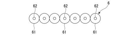
- the distal optical fiber 6 in this embodiment is composed of a plurality of (seven in the illustrated example) single-core fibers 61 each having one core 62 .
- the number of single-core fibers 61 forming the distal optical fiber 6 corresponds to the number of cores 52 (see FIG. 4) of the multi-core fiber 51 forming the proximal optical fiber 5 .
- FIG. 3 at the proximal end (second end) 6B in the longitudinal direction of the distal optical fiber 6 located on the proximal optical fiber 5 side, as shown in FIG. 61 are arranged so as to correspond to the arrangement of the plurality of cores 52 of the proximal end optical fiber 5 shown in FIG. Specifically, as shown in FIG. 5, at the proximal end of the distal end side optical fiber 6, a plurality of single core fibers 61 are arranged on the same circumference around a predetermined axis C2. Also, one single core fiber 61 is arranged so as to be positioned on a predetermined axis C2.
- FIG. 3 at the tip (first end) 6A in the longitudinal direction of the tip-side optical fiber 6 positioned on the optical connector 3 side, as shown in FIG. They are arranged so as to correspond to the optical connector 3 (ferrule). Specifically, as shown in FIG. 6, a plurality of single-core fibers 61 are arranged in a line at the tip of the tip-side optical fiber 6 in a straight line direction (horizontal direction in FIG. 6) perpendicular to its longitudinal direction.
- the connecting portion 7 connects the proximal side optical fiber 5 and the distal side optical fiber 6 .
- the connecting portion 7 has a role of optically coupling the plurality of cores 52 (see FIG. 4) of the proximal side optical fiber 5 and the plurality of cores 62 (see FIG. 5) of the distal side optical fiber 6 individually.
- the connecting portion 7 of this embodiment is a connector connecting portion 71 that mechanically connects the proximal side optical fiber 5 and the distal side optical fiber 6 .
- the connector connecting portion 71 has a proximal side connector 72 , a distal side connector 73 and an adapter 74 .
- the proximal side connector 72 is provided at the distal end portion of the proximal side optical fiber 5 and has a connection surface 721 from which the distal end of the proximal side optical fiber 5 is exposed.
- an insertion hole is formed in the base end connector 72 . The distal end of the proximal-side optical fiber 5 is inserted through this insertion hole and exposed from the connection surface 721 of the proximal-side connector 72 .
- the distal connector 73 is provided at the proximal end of the distal optical fiber 6 and has a connection surface 731 from which the proximal end of the distal optical fiber 6 is exposed. Although not shown, an insertion hole is formed in the distal connector 73 . The proximal end of the distal optical fiber 6 is inserted through this insertion hole and exposed from the connection surface 731 of the distal connector 73 .
- the adapter 74 connects the proximal side connector 72 and the distal side connector 73 to connect the core 52 (see FIG. 4) of the proximal side optical fiber 5 and the core 62 (see FIG. 5) of the distal side optical fiber 6. optically couple.
- the adapter 74 of this embodiment is formed in a tubular shape with both ends in the axial direction open.
- the proximal side connector 72 and the distal side connector 73 are inserted into the openings at both ends of the adapter 74 so that the connection surfaces 721 and 731 of the proximal side connector 72 and the distal side connector 73 face each other.
- the connecting surfaces 721 and 731 of the proximal side connector 72 and the distal side connector 73 are brought into contact with each other, and the core 52 of the proximal side optical fiber 5 and the core 62 of the distal side optical fiber 6 are optically coupled. can be done.
- the lengths of the plurality of lead-out optical fibers 2 lead out from the end of the sheath S are different.
- all lead-out optical fibers 2 have different lengths.
- the lengths of the plurality of base end-side optical fibers 5 constituting the plurality of lead-out optical fibers 2 are different.
- the lengths of the plurality of tip-side optical fibers 6 constituting the plurality of lead-out optical fibers 2 are equal.
- the plurality of connection portions 7 located at the respective distal end portions of the plurality of proximal-side optical fibers 5
- the part 71) is offset in the lead-out direction of the lead-out optical fiber 2 .
- the optical connector 3 is provided at the tip of each lead-out optical fiber 2 in the lead-out direction, that is, at the tip of each tip-side optical fiber 6 .
- the optical connector 3 has a connection end face 31 where the tip of the tip end optical fiber 6 is exposed.
- the optical connector 3 is formed with an insertion hole. The tip of the tip-side optical fiber 6 is inserted through this insertion hole and exposed from the connection end face 31 of the optical connector 3 .
- the insertion hole of the optical connector 3 is arranged such that a plurality of single-core fibers 61 (see FIG. 6) forming the distal end-side optical fiber 6 are arranged in a line in a straight line direction orthogonal to the longitudinal direction thereof.
- the connecting portions 7 of all lead-out optical fibers 2 are positioned inside the tubular member 100.
- the length of all connectorized optical fibers 1 is shorter than the length of the tubular member 100 .
- the optical connector 3 is terminated to the first end (tip) 6A in the longitudinal direction of the tip-side optical fiber 6 (first step ).
- the terminating work of the optical connector 3 in the first step includes the insertion work of inserting the tip end side optical fiber 6 into the optical connector 3, the connection end face 31 of the optical connector 3 and the tip end side optical fiber 6 exposed at this connection end face 31.
- a polishing work for polishing the tip and an inspection work for inspecting the optical loss at the tip of the tip end side optical fiber 6 exposed at the connection end face 31 are included.
- the distal end connector 73 is terminated to the second end portion (base end portion) 6B of the distal end optical fiber 6 .
- the termination work of the distal connector 73 may include insertion work, polishing work, and inspection work similar to the termination work of the optical connector 3 described above.
- a first step is performed for a plurality of distal optical fibers 6 .
- the lengths of the plurality of tip-side optical fibers 6 are set in advance so that the lengths of the plurality of tip-side optical fibers 6 are equal.
- a plurality of base end side optical fibers 5 are led out from the end of the sheath S of the optical cable C (second step).
- the lengths of the plurality of proximal side optical fibers 5 are set so that the plurality of proximal side optical fibers 5 have different lengths.
- the proximal end connector 72 is terminated to the distal end portion of the proximal end optical fiber 5 .
- the termination operation of the proximal connector 72 may include insertion, polishing, and inspection operations similar to those described above.
- the second step may be performed, for example, before or after the first step, or simultaneously with the first step.
- the lead-out optical fiber 2 having the base-side optical fiber 5 and the distal-side optical fiber 6 is constructed. Further, an optical fiber 1 with a connector extending from the end of the sheath S and having a lead-out optical fiber 2 and an optical connector 3 is constructed.
- the proximal side optical fiber 5 and the distal side optical fiber 6 are connected by the connector connecting portion 71 .
- the adapter 74 is used to connect the proximal connector 72 provided at the distal end of the proximal optical fiber 5 and the second end (base end) 6B of the distal optical fiber 6.
- the proximal side optical fiber 5 and the distal side optical fiber 6 are connected by abutting the distal side connector 73 that has been provided.
- the lengths of the plurality of tip-side optical fibers 6 are set so that the lengths of the plurality of tip-side optical fibers 6 are equal.
- the lengths of the plurality of proximal side optical fibers 5 are set so that the plurality of proximal side optical fibers 5 have different lengths. Therefore, in the state after the third step, the plurality of lead-out optical fibers 2 have different lengths. The above completes the manufacturing method of the optical cable structure.
- the lengths of the plurality of lead-out optical fibers 2 lead out from the end of the sheath S are different. Therefore, the plurality of optical connectors 3 provided at the tip portions of the plurality of lead-out optical fibers 2 can be shifted in the lead-out direction of the lead-out optical fibers 2 . Thereby, it is possible to prevent the plurality of optical connectors 3 from being bulky in the radial direction of the optical cable C. FIG. Therefore, it is possible to accommodate a plurality of optical fibers 1 with connectors in the tubular member 100 having a small diameter.
- the distal end side optical fiber 6 is It can be connected to fiber 5 . That is, before connecting the distal optical fiber 6 to the proximal optical fiber 5, the optical connector 3 can be terminated. Therefore, even if the lengths of the lead-out optical fibers 2 in the optical cable structure after manufacture are different, the termination operation of the optical connector 3 for the lead-out optical fibers 2 accommodated in the tubular member 100 can be easily performed. can be done.
- the termination work (especially polishing work) of the optical connector 3 to the tip-side optical fibers 6 and inspection work) can be easily performed.
- the lengths of the plurality of proximal side optical fibers 5 extending from the end of the sheath S are different. Therefore, the plurality of connecting portions 7 provided at the distal end portions of the plurality of base-end-side optical fibers 5 can be shifted in the longitudinal direction of the lead-out optical fiber 2 . Thereby, it is possible to prevent the plurality of connecting portions 7 from being bulky in the radial direction of the optical cable C. As shown in FIG. Therefore, it is possible to easily accommodate a plurality of optical fibers 1 with connectors in the tubular member 100 having a small diameter. In the first embodiment, since the diameter of the connector connection portion 71 is larger than the diameter of the lead-out optical fiber 2, the above effect is particularly useful.
- the lengths of the plurality of front end optical fibers 6 are equal.
- an optical cable structure can be manufactured using a plurality of tip-side optical fibers 6 having the same length. Therefore, it is possible to efficiently manufacture the optical cable structure.
- the proximal side optical fiber 5 and the distal side optical fiber 6 are mechanically connected by the connector connecting portion 71 . This makes it possible to easily connect the proximal side optical fiber 5 and the distal side optical fiber 6 without using a device such as a fusion splicer.
- the optical cable structure of the second embodiment includes a plurality of optical fibers 1B with connectors led out from the end of the sheath S of the optical cable C and accommodated in the tubular member 100, as in the first embodiment.
- the lead-out optical fiber 2B of each connector-equipped optical fiber 1B has a connection portion 7B that connects the proximal-side optical fiber 5 and the distal-side optical fiber 6 .
- the splicing portion 7B of the second embodiment is a fusion splicing portion 71B that splices the proximal side optical fiber 5 and the distal side optical fiber 6 by fusion splicing.
- the fusion splicer 71B of the second embodiment is constructed separately from the proximal side optical fiber 5 and the distal side optical fiber 6.
- FIG. 10 to 11 the fusion splicer 71B of the second embodiment is constructed separately from the proximal side optical fiber 5 and the distal side optical fiber 6.
- the fusion splicing portion 71B has a proximal side portion 72B and a distal side portion 73B.
- the base end portion 72B is composed of a multi-core fiber having multiple cores.
- the cross-sectional shape of the proximal side portion 72B is the same as the cross-sectional shape of the proximal side optical fiber 5 shown in FIG.
- the distal portion 73B is composed of a plurality of single-core fibers having one core.
- the cross-sectional shape of the tip-side portion 73B is the same as the cross-sectional shape of the proximal end portion side of the tip-side optical fiber 6 shown in FIG.
- the proximal side portion 72B and the distal side portion 73B are arranged in the longitudinal direction of these cores (horizontal direction in FIG. 10) and joined by fusion or the like. Thereby, the plurality of cores of the proximal side portion 72B and the plurality of cores of the distal side portion 73B are optically coupled individually.
- an optical connector for example, an MT ferrule
- the rotation direction of the optical fiber optical fiber
- the end of the optical fiber is a single-core fiber, the rotational directionality of the optical fiber is lost, so the above alignment work is not necessary.
- the proximal end portion 72B of the fusion splicing portion 71B is fusion spliced to the distal end portion of the proximal end optical fiber 5 .
- the tip end portion 73B of the fusion splicing portion 71B is fusion spliced to the base end portion of the tip end optical fiber 6 .
- the core 52 (see FIG. 4) of the proximal side optical fiber 5 and the core 62 (see FIG. 5) of the distal side optical fiber 6 are connected to each other by the fusion splicing portion 71B (the proximal side portion 72B and the distal side portion 73B). ) are optically coupled through the core of
- the length of the fusion splicing portion 71B is shorter than the lengths of the proximal side optical fiber 5 and the distal side optical fiber 6 .
- the length of the fusion splicing portion 71B is the same among the plurality of lead-out optical fibers 2B.
- the fusion splicing portion 71B may have a protective sleeve that protects the fusion spliced portions with the proximal side optical fiber 5 and the distal side optical fiber 6, for example.
- the diameter dimension of the fusion splicing portion 71B is larger than the diameter dimension of the derived optical fiber 2 .
- the distal end side optical fiber 6 is not terminated with the distal side connector 73 (see FIGS. 7 and 8) in the first step, and the proximal side optical fiber 5 is terminated in the second step. It differs from the manufacturing method of the first embodiment in that the base-end connector 72 (see FIGS. 7 and 8) is not terminated.
- the second ends (base ends) 6B of the plurality of distal side optical fibers 6 are connected to the distal ends of the plurality of proximal side optical fibers 5, respectively. The method of doing is different from the manufacturing method of the first embodiment.
- the third step in the manufacturing method of the second embodiment will be described below.
- the distal end portion of the proximal side optical fiber 5 and the proximal end portion of the distal side optical fiber 6 are fusion spliced by the fusion splicing portion 71B. do. Specifically, first, as shown in FIGS. 11 and 12, a fusion splicing portion 71B is arranged between the distal end portion of the proximal side optical fiber 5 and the proximal end portion of the distal side optical fiber 6. FIG. After that, as shown in FIG. 10, the tip of the proximal end optical fiber 5 is fusion spliced to the proximal end portion 72B of the fusion splicing portion 71B.
- the proximal end portion of the distal end side optical fiber 6 is fusion spliced to the distal end portion 73B of the fusion splicing portion 71B.
- the manufacturing method of the second embodiment is completed by performing the third step of the second embodiment described above after the first step and the second step.
- the same effects as those of the first embodiment are obtained. Further, according to the second embodiment, the proximal side optical fiber 5 and the distal side optical fiber 6 are fusion-spliced. Thereby, the proximal side optical fiber 5 and the distal side optical fiber 6 can be connected with higher reliability.
- the fusion splicing portion 71B is configured separately from the proximal side optical fiber 5 and the distal side optical fiber 6 .
- the fusion splicing portion 71B includes a proximal portion 72B composed of a multi-core fiber similar to the proximal optical fiber 5 and a distal portion 72B composed of a plurality of single core fibers similar to the distal optical fiber 6. and a portion 73B. Therefore, the proximal side optical fiber 5 and the distal side optical fiber 6 can be connected by fusion splicing between multi-core fibers and fusion splicing between a plurality of single core fibers.
- fusion splicing between optical fibers of the same type can be performed more easily than fusion splicing between optical fibers of different types (that is, fusion splicing between a multi-core fiber and a plurality of single-core fibers).
- fusion splicing between optical fibers of different types that is, fusion splicing between a multi-core fiber and a plurality of single-core fibers.
- a large number of fusion splicing portions 71B having the proximal side portion 72B and the distal side portion 73B should be manufactured in advance. can be done. This makes it possible to efficiently perform fusion splicing between the plurality of proximal side optical fibers 5 and the plurality of distal side optical fibers 6 . From the above, it is possible to efficiently manufacture the optical cable structure.
- the length of the fusion splicing portion 71B may differ among the plurality of lead-out optical fibers 2B.
- the lengths of the plurality of lead-out optical fibers 2B may be varied by varying the lengths of the fusion splicing portions 71B among the plurality of lead-out optical fibers 2B.
- the length of the fusion splicing portion 71B may be equal to or longer than the lengths of the proximal side optical fiber 5 and the distal side optical fiber 6, for example.
- the fusion splicing portion 71B may be composed of, for example, the tip portion of the proximal side optical fiber 5 and the proximal portion of the distal side optical fiber 6. That is, the proximal side optical fiber 5 and the distal side optical fiber 6 may be directly fusion-spliced.
- the lengths of the plurality of proximal end optical fibers 5 may be equal.
- the lengths of the leading optical fibers 2 and 2B may be varied by varying the lengths of the distal optical fibers 6, for example.
- both the proximal side optical fiber 5 and the distal side optical fiber 6 may be, for example, a multi-core fiber 51, or may be composed of a plurality of single-core fibers 61, for example. Also, the proximal side optical fiber 5 and the distal side optical fiber 6 may be one single core fiber 61 .
- the lengths of the plurality of tip-side optical fibers 6 may be set so that the lengths of the plurality of tip-side optical fibers 6 are different.
- the lengths of the plurality of proximal side optical fibers 5 may be set such that the lengths of the plurality of proximal side optical fibers 5 are different, as in the above embodiment.
- the lengths of the plurality of proximal side optical fibers 5 may be set so that the lengths of the plurality of proximal side optical fibers 5 are equal.
- the lengths of the plurality of distal side optical fibers 6 and the plurality of proximal side optical fibers 5 can be set in this way, the lengths of the plurality of lead-out optical fibers 2 and 2B in the optical cable structure after manufacture can be made different.
- the lengths of all lead-out optical fibers 2, 2B extending from the end of the sheath S do not have to be different.
- some of the lead-out optical fibers 2, 2B may have the same length.
- the plurality of lead-out optical fibers 2, 2B extending from the end of the sheath S are divided into a plurality of groups, the lengths of the plurality of lead-out optical fibers 2, 2B constituting the same group are made the same, and different groups are led out.
- the optical fibers 2, 2B may have different lengths.
- the plurality of optical connectors 3 provided at the tips of the plurality of lead-out optical fibers 2, 2B forming the same group are arranged at the same position in the lead-out direction of the lead-out optical fibers 2, 2B. Also, the optical connectors 3 provided at the tips of the lead-out optical fibers 2 and 2B of different groups are shifted in the lead-out direction of the lead-out optical fibers 2 and 2B.
Landscapes
- Physics & Mathematics (AREA)
- General Physics & Mathematics (AREA)
- Optics & Photonics (AREA)
- Engineering & Computer Science (AREA)
- Plasma & Fusion (AREA)
- Mechanical Coupling Of Light Guides (AREA)
Abstract
光ケーブル構造は、光ケーブル(C)のシース(S)の端部から導出されて管状部材(100)に収容される複数のコネクタ付き光ファイバ(1)を備える。複数のコネクタ付き光ファイバ(1)は、それぞれシース(S)の端部から導出される導出光ファイバ(2)と、導出光ファイバ(2)の先端部に設けられた光コネクタ(3)と、を備える。複数の導出光ファイバ(2)の長さは異なる。 複数の導出光ファイバ(2)は、それぞれ、シース(S)の端部側に位置する基端側光ファイバ(5)と、光コネクタ(3)側に位置する先端側光ファイバ(6)と、基端側光ファイバ(5)と先端側光ファイバ(6)とを接続する接続部(7)と、を有する。複数のコネクタ付き光ファイバ(1)を管状部材(100)に収容した状態では、複数の接続部(7)が管状部材(100)の内部に位置する。
Description
本発明は、光ケーブル構造及び光ケーブル構造の製造方法に関する。
本願は、2021年12月8日に日本に出願された特願2021-199309号について優先権を主張し、その内容をここに援用する。
本願は、2021年12月8日に日本に出願された特願2021-199309号について優先権を主張し、その内容をここに援用する。
従来、ダクトの中に光ケーブルを挿通して光配線を敷設する際には、光ケーブルの先端部分を管状部材(牽引端)に収容して保護することが行われている。管状部材の内部には、光ケーブルの先端部分として、各先端部に光コネクタを成端した複数の光ファイバが収容されることがある。
特許文献1には、光ケーブルの先端部分を構成する複数の光ファイバの長さを異ならせて、複数の光ファイバに成端した複数の光コネクタを光ファイバ(光ケーブル)の長さ方向にずらして配置した光ケーブル構造が開示されている。このような光ケーブル構造では、複数の光コネクタが光ケーブルの径方向に嵩張ることを抑制して、これら複数の光コネクタを収容する管状部材の径寸法を小さく維持できる。このため、先端部に光コネクタを有する光ファイバの数が多くても、光ケーブルを細いダクトの中に挿通させることができる。
特許文献1には、光ケーブルの先端部分を構成する複数の光ファイバの長さを異ならせて、複数の光ファイバに成端した複数の光コネクタを光ファイバ(光ケーブル)の長さ方向にずらして配置した光ケーブル構造が開示されている。このような光ケーブル構造では、複数の光コネクタが光ケーブルの径方向に嵩張ることを抑制して、これら複数の光コネクタを収容する管状部材の径寸法を小さく維持できる。このため、先端部に光コネクタを有する光ファイバの数が多くても、光ケーブルを細いダクトの中に挿通させることができる。
しかしながら、特許文献1に開示された光ケーブル構造を製造しようとする場合、複数の光ファイバの各先端部に対する光コネクタの成端作業を効率よく行うことが難しい。例えば、光コネクタの成端作業を効率よく行うためには、複数の光ファイバの先端部の位置を揃えることが好ましいが、複数の光ファイバの長さが異なるため、複数の光ファイバの先端部の位置を揃えることは難しい。
本発明は、上述した事情に鑑みてなされたものであって、管状部材に収容される光ケーブルの先端部分を構成する複数の光ファイバに対する光コネクタの成端作業を簡単に行うことが可能な光ケーブル構造及び光ケーブル構造の製造方法を提供することを目的とする。
本発明の一態様に係る光ケーブル構造は、光ケーブルのシースの端部から導出され、所定の長さを有する管状部材に収容される複数のコネクタ付き光ファイバを有する光ケーブル構造であって、複数の前記コネクタ付き光ファイバは、それぞれ、前記シースの端部から導出される導出光ファイバと、前記導出光ファイバの導出方向の先端部に設けられた光コネクタと、を備える。前記シースの端部から導出される複数の前記導出光ファイバのうち少なくとも一部の前記導出光ファイバの長さは異なる。複数の前記導出光ファイバは、それぞれ、前記シースの端部側に位置する基端側光ファイバと、前記光コネクタ側に位置する先端側光ファイバと、前記基端側光ファイバと前記先端側光ファイバとを接続する接続部と、を有する。複数の前記コネクタ付き光ファイバを前記管状部材に収容した状態では、複数の前記導出光ファイバの接続部が、前記管状部材の内部に位置する。
本発明の一態様に係る光ケーブル構造の製造方法は、光ケーブルのシースの端部から導出され、所定の長さを有する管状部材に収容される複数のコネクタ付き光ファイバを有する光ケーブル構造の製造方法であって、先端側光ファイバの長手方向の第一端部に光コネクタを成端する第一工程と、前記シースの端部から複数の基端側光ファイバを導出させる第二工程と、前記第一工程及び前記第二工程の後に、複数の前記先端側光ファイバの長手方向の第二端部を、複数の前記基端側光ファイバの先端部にそれぞれ接続することで、前記基端側光ファイバ及び先端側光ファイバから構成される導出光ファイバと前記光コネクタとを有し、前記シースの端部から延びる複数の前記コネクタ付き光ファイバを構成する第三工程と、を備える。前記シースの端部から導出される複数の前記導出光ファイバのうち少なくとも一部の前記導出光ファイバの長さが異なるように、前記第三工程の前に、複数の前記先端側光ファイバの長さ及び複数の前記基端側光ファイバの長さのうち少なくとも一方を設定する。
本発明によれば、光ケーブルの先端部分を構成し、管状部材に収容される複数の導出光ファイバに対する光コネクタの成端作業を簡単に行うことができる。
<第一実施形態>
以下、本発明の第一実施形態について図1から図8を参照して説明する。
図1,2に示すように、第一実施形態の光ケーブル構造は、光ケーブルCのシースSの端部から導出され、光ケーブルCの先端部分を構成する複数のコネクタ付き光ファイバ1を有する。図示例におけるコネクタ付き光ファイバ1の数は3つであるが、これに限ることはない。複数のコネクタ付き光ファイバ1は、所定の長さを有する管状部材100に収容される。
以下、本発明の第一実施形態について図1から図8を参照して説明する。
図1,2に示すように、第一実施形態の光ケーブル構造は、光ケーブルCのシースSの端部から導出され、光ケーブルCの先端部分を構成する複数のコネクタ付き光ファイバ1を有する。図示例におけるコネクタ付き光ファイバ1の数は3つであるが、これに限ることはない。複数のコネクタ付き光ファイバ1は、所定の長さを有する管状部材100に収容される。
図1に示すように、管状部材100は、複数のコネクタ付き光ファイバ1を覆う。管状部材100は、光ケーブルCを建物のダクト等に通す際に、複数のコネクタ付き光ファイバ1を保護する役割を有する。また、管状部材100は、光ケーブルCを上記ダクト等に通す際に牽引される牽引端としての役割も有する。管状部材100は、光ケーブルCをダクト等に通した後に光ケーブルCから取り外される。
管状部材100は、管状本体101と、ヘッド102と、を有する。管状本体101は、コネクタ付き光ファイバ1を収容する管状に形成されている。管状本体101は、例えば可撓性を有してよい。ヘッド102は、管状本体101の先端部に設けられ、管状本体101の先端側の開口を覆っている。ヘッド102の先端にはプーリングアイ103が設けられている。プーリングアイ103にロープ等を結んで引っ張ることで、光ケーブルCをダクト等に通しやすくなる。
管状部材100は、管状本体101に複数のコネクタ付き光ファイバ1を収容した上で、管状本体101の基端部をネジ等によってシースSの端部に固定された保持具105に保持させることで、光ケーブルCに対して着脱可能に取り付けられる。
管状部材100は、管状本体101に複数のコネクタ付き光ファイバ1を収容した上で、管状本体101の基端部をネジ等によってシースSの端部に固定された保持具105に保持させることで、光ケーブルCに対して着脱可能に取り付けられる。
図1から図3に示すように、光ケーブルCの各コネクタ付き光ファイバ1は、シースSの端部から導出される導出光ファイバ2と、導出光ファイバ2の導出方向の先端部に設けられた光コネクタ3と、を有する。
導出光ファイバ2は、光信号を伝送するためのコア52,62(図4から図6参照)を有する。導出光ファイバ2におけるコア52,62の数は、例えば1つでもよいが、本実施形態では複数である。
導出光ファイバ2は、光信号を伝送するためのコア52,62(図4から図6参照)を有する。導出光ファイバ2におけるコア52,62の数は、例えば1つでもよいが、本実施形態では複数である。
導出光ファイバ2は、基端側光ファイバ5と、先端側光ファイバ6と、接続部7と、を有する。
基端側光ファイバ5は、シースSの端部側に位置する導出光ファイバ2の基端側の部位である。図4に示すように、本実施形態における基端側光ファイバ5は、複数(図示例では7つ)のコア52を有するマルチコアファイバ51である。マルチコアファイバ51を構成する複数のコア52は、基端側光ファイバ5の長手方向から見て基端側光ファイバ5の軸線C1を中心とする同一円周上に配置され、軸線C1回りに間隔をあけて並んでいる。また、図示例のマルチコアファイバ51では、基端側光ファイバ5の軸線C1上に1つのコア52が配置されている。
図1から図3に示すように、先端側光ファイバ6は、光コネクタ3側に位置する導出光ファイバ2の先端側の部位である。図5及び図6に示すように、本実施形態における先端側光ファイバ6は、1つのコア62を有する複数(図示例では7つ)のシングルコアファイバ61によって構成されている。先端側光ファイバ6を構成するシングルコアファイバ61の数は、基端側光ファイバ5を構成するマルチコアファイバ51のコア52(図4参照)の数に対応している。
図3に示すように、基端側光ファイバ5側に位置する先端側光ファイバ6の長手方向の基端部(第二端部)6Bでは、図5に示すように、複数のシングルコアファイバ61が図4に示した基端側光ファイバ5の複数のコア52の配列に対応するように並べられている。具体的に、先端側光ファイバ6の基端部においては、図5に示すように、複数のシングルコアファイバ61が所定の軸線C2を中心とする同一円周上に配置されている。また、1つのシングルコアファイバ61は、所定の軸線C2上に位置するように配置されている。
一方、図3に示すように、光コネクタ3側に位置する先端側光ファイバ6の長手方向の先端部(第一端部)6Aでは、図6に示すように、複数のシングルコアファイバ61が光コネクタ3(フェルール)に対応するように並べられている。具体的に、先端側光ファイバ6の先端部においては、図6に示すように、複数のシングルコアファイバ61がその長手方向に直交する直線方向(図6において左右方向)に一列に並べられている。
図1から図3に示すように、接続部7は、基端側光ファイバ5と先端側光ファイバ6とを接続する。接続部7は、基端側光ファイバ5の複数のコア52(図4参照)と先端側光ファイバ6の複数のコア62(図5参照)とを個々に光学的に結合する役割を有する。本実施形態の接続部7は、基端側光ファイバ5と先端側光ファイバ6とを機械的に接続するコネクタ接続部71である。
図3及び図7に示すように、コネクタ接続部71は、基端側コネクタ72と、先端側コネクタ73と、アダプタ74と、を有する。
基端側コネクタ72は、基端側光ファイバ5の先端部に設けられ、基端側光ファイバ5の先端が露出する接続面721を有する。図示しないが、基端側コネクタ72には、挿通孔が形成されている。基端側光ファイバ5の先端部が、この挿通孔に挿通され、基端側コネクタ72の接続面721から露出する。
先端側コネクタ73は、先端側光ファイバ6の基端部に設けられ、先端側光ファイバ6の基端が露出する接続面731を有する。図示しないが、先端側コネクタ73には、挿通孔が形成されている。先端側光ファイバ6の基端部が、この挿通孔に挿通され、先端側コネクタ73の接続面731から露出する。
基端側コネクタ72は、基端側光ファイバ5の先端部に設けられ、基端側光ファイバ5の先端が露出する接続面721を有する。図示しないが、基端側コネクタ72には、挿通孔が形成されている。基端側光ファイバ5の先端部が、この挿通孔に挿通され、基端側コネクタ72の接続面721から露出する。
先端側コネクタ73は、先端側光ファイバ6の基端部に設けられ、先端側光ファイバ6の基端が露出する接続面731を有する。図示しないが、先端側コネクタ73には、挿通孔が形成されている。先端側光ファイバ6の基端部が、この挿通孔に挿通され、先端側コネクタ73の接続面731から露出する。
アダプタ74は、基端側コネクタ72と先端側コネクタ73とを接続して、基端側光ファイバ5のコア52(図4参照)と先端側光ファイバ6のコア62(図5参照)とを光学的に結合する。本実施形態のアダプタ74は、軸方向の両端が開口する筒状に形成されている。アダプタ74の両端の開口には、基端側コネクタ72及び先端側コネクタ73の接続面721,731が向かい合うように、基端側コネクタ72及び先端側コネクタ73が挿入される。これにより、基端側コネクタ72及び先端側コネクタ73の接続面721,731を突き合せて、基端側光ファイバ5のコア52と先端側光ファイバ6のコア62とを光学的に結合することができる。
図1及び図2に示すように、シースSの端部から導出される複数の導出光ファイバ2の長さは異なっている。本実施形態では、全ての導出光ファイバ2の長さが異なっている。また、複数の導出光ファイバ2を構成する複数の基端側光ファイバ5の長さが異なっている。
さらに、複数の導出光ファイバ2を構成する複数の先端側光ファイバ6の長さが等しい。
複数の導出光ファイバ2を構成する複数の基端側光ファイバ5の長さが異なっていることで、複数の基端側光ファイバ5の各先端部に位置する複数の接続部7(コネクタ接続部71)は、導出光ファイバ2の導出方向においてずれて位置する。
さらに、複数の導出光ファイバ2を構成する複数の先端側光ファイバ6の長さが等しい。
複数の導出光ファイバ2を構成する複数の基端側光ファイバ5の長さが異なっていることで、複数の基端側光ファイバ5の各先端部に位置する複数の接続部7(コネクタ接続部71)は、導出光ファイバ2の導出方向においてずれて位置する。
光コネクタ3は、各導出光ファイバ2の導出方向の先端部に設けられる、すなわち、各先端側光ファイバ6の先端部に設けられる。図3に示すように、光コネクタ3は、先端側光ファイバ6の先端が露出する接続端面31を有する。図示しないが、光コネクタ3には、挿通孔が形成されている。先端側光ファイバ6の先端部が、この挿通孔に挿通され、光コネクタ3の接続端面31から露出する。本実施形態において、光コネクタ3の挿通孔は、先端側光ファイバ6を構成する複数のシングルコアファイバ61(図6参照)がその長手方向に直交する直線方向に一列に並んだ状態で、これら複数のシングルコアファイバ61を挿通させるように形成されている。
前述したように、シースSの端部から導出した複数の導出光ファイバ2の長さが異なっている。このため、複数の導出光ファイバ2の各先端部に設けられた複数の光コネクタ3は、導出光ファイバ2の導出方向においてずれて位置する。
前述したように、シースSの端部から導出した複数の導出光ファイバ2の長さが異なっている。このため、複数の導出光ファイバ2の各先端部に設けられた複数の光コネクタ3は、導出光ファイバ2の導出方向においてずれて位置する。
図1に示すように、構成される光ケーブルCの複数のコネクタ付き光ファイバ1が管状部材100に収容された状態では、全ての導出光ファイバ2の接続部7が管状部材100の内部に位置する。
また、全てのコネクタ付き光ファイバ1の長さは、管状部材100の長さよりも短い。
これにより、全ての導出光ファイバ2を湾曲などさせなくても、コネクタ付き光ファイバ1を管状部材100に収容することができる。
また、全てのコネクタ付き光ファイバ1の長さは、管状部材100の長さよりも短い。
これにより、全ての導出光ファイバ2を湾曲などさせなくても、コネクタ付き光ファイバ1を管状部材100に収容することができる。
次に、本実施形態の光ケーブル構造の製造方法について説明する。
光ケーブル構造を製造する際には、はじめに図7及び図8に示すように、先端側光ファイバ6の長手方向の第一端部(先端部)6Aに光コネクタ3を成端する(第一工程)。第一工程における光コネクタ3の成端作業には、先端側光ファイバ6を光コネクタ3に挿通させる挿通作業、光コネクタ3の接続端面31及びこの接続端面31に露出する先端側光ファイバ6の先端を研磨する研磨作業、及び、接続端面31に露出する先端側光ファイバ6の先端の光学的損失を検査する検査作業が含まれる。また、本実施形態の第一工程では、先端側光ファイバ6の第二端部(基端部)6Bに先端側コネクタ73を成端する。先端側コネクタ73の成端作業は、前述した光コネクタ3の成端作業と同様の挿通作業、研磨作業、検査作業を含んでよい。
第一工程は、複数の先端側光ファイバ6に対して実施される。なお、本実施形態では、第一工程の前に、複数の先端側光ファイバ6の長さが等しくなるように、複数の先端側光ファイバ6の長さを予め設定しておく。
また、光ケーブル構造を製造する際には、光ケーブルCのシースSの端部から複数の基端側光ファイバ5を導出させる(第二工程)。本実施形態の第二工程では、複数の基端側光ファイバ5の長さが異なるように、複数の基端側光ファイバ5の長さを設定する。また、本実施形態の第二工程では、基端側光ファイバ5の先端部に基端側コネクタ72を成端する。基端側コネクタ72の成端作業は、前述と同様の挿通作業、研磨作業、検査作業を含んでよい。
第二工程は、例えば第一工程の前又は後、あるいは、第一工程と同時に行われてもよい。
第二工程は、例えば第一工程の前又は後、あるいは、第一工程と同時に行われてもよい。
第一工程及び第二工程の後には、図2及び図3に示すように、複数の先端側光ファイバ6の第二端部(基端部)6Bを、複数の基端側光ファイバ5の先端部にそれぞれ接続する(第三工程)。この第三工程を実施することで、基端側光ファイバ5及び先端側光ファイバ6を有する導出光ファイバ2が構成される。また、導出光ファイバ2と光コネクタ3とを有し、シースSの端部から延びるコネクタ付き光ファイバ1が構成される。
本実施形態の第三工程では、コネクタ接続部71によって基端側光ファイバ5と先端側光ファイバ6とを接続する。具体的には、アダプタ74を利用して、基端側光ファイバ5の先端部に設けられた基端側コネクタ72と、先端側光ファイバ6の第二端部(基端部)6Bに設けられた先端側コネクタ73とを突き合せることで、基端側光ファイバ5と先端側光ファイバ6とが接続される。
本実施形態の第三工程では、コネクタ接続部71によって基端側光ファイバ5と先端側光ファイバ6とを接続する。具体的には、アダプタ74を利用して、基端側光ファイバ5の先端部に設けられた基端側コネクタ72と、先端側光ファイバ6の第二端部(基端部)6Bに設けられた先端側コネクタ73とを突き合せることで、基端側光ファイバ5と先端側光ファイバ6とが接続される。
本実施形態の製造方法では、前述したように、第一工程の前に、複数の先端側光ファイバ6の長さが等しくなるように、複数の先端側光ファイバ6の長さが設定される。また、第二工程では、複数の基端側光ファイバ5の長さが異なるように、複数の基端側光ファイバ5の長さが設定される。このため、第三工程後の状態では、複数の導出光ファイバ2の長さが異なる。
以上により、光ケーブル構造の製造方法が完了する。
以上により、光ケーブル構造の製造方法が完了する。
以上説明したように、第一実施形態の光ケーブル構造及びその製造方法では、シースSの端部から導出された複数の導出光ファイバ2の長さが異なる。このため、複数の導出光ファイバ2の各先端部に設けられた複数の光コネクタ3を、導出光ファイバ2の導出方向においてずらして位置させることができる。これにより、複数の光コネクタ3が光ケーブルCの径方向に嵩張ることを抑制できる。しがって、複数のコネクタ付き光ファイバ1を径寸法が小さい管状部材100に収容することが可能となる。
また、第一実施形態の光ケーブル構造及びその製造方法では、先端側光ファイバ6の先端部(第一端部)6Aに光コネクタ3を成端した後に、先端側光ファイバ6を基端側光ファイバ5に接続することができる。すなわち、先端側光ファイバ6を基端側光ファイバ5に接続する前に、光コネクタ3の成端作業を実施することができる。このため、製造後の光ケーブル構造における複数の導出光ファイバ2の長さが異なっていても、管状部材100に収容される複数の導出光ファイバ2に対する光コネクタ3の成端作業を簡単に行うことができる。具体的には、複数の先端側光ファイバ6の先端部(第一端部)6Aの位置を簡単に揃えることができるため、先端側光ファイバ6に対する光コネクタ3の成端作業(特に研磨作業や検査作業)を簡単に行うことができる。
また、第一実施形態の光ケーブル構造及びその製造方法では、シースSの端部から延びる複数の基端側光ファイバ5の長さが異なる。このため、複数の基端側光ファイバ5の各先端部に設けられた複数の接続部7を、導出光ファイバ2の長手方向においてにずらして位置させることができる。これにより、複数の接続部7が光ケーブルCの径方向に嵩張ることを抑制できる。したがって、複数のコネクタ付き光ファイバ1を径寸法が小さい管状部材100に簡単に収容することが可能となる。第一実施形態では、コネクタ接続部71の径寸法が導出光ファイバ2の径寸法よりも大きいため、上記効果は特に有用である。
また、第一実施形態の光ケーブル構造及びその製造方法では、複数の先端側光ファイバ6の長さが等しい。これにより、同一長さの複数の先端側光ファイバ6を用いて光ケーブル構造を製造することができる。したがって、光ケーブル構造を効率よく製造することが可能となる。
また、第一実施形態の光ケーブル構造及びその製造方法では、基端側光ファイバ5と先端側光ファイバ6とが、コネクタ接続部71によって機械的に接続される。これにより、融着接続機等の装置を用いることなく、基端側光ファイバ5と先端側光ファイバ6とを簡単に接続することができる。
<第二実施形態>
次に、本発明の第二実施形態に係る光ケーブル構造及びその製造方法について、図9から図12を参照して説明する。以降の説明において、既に説明したものと共通する構成については、同一の符号を付して重複する説明を省略する。
次に、本発明の第二実施形態に係る光ケーブル構造及びその製造方法について、図9から図12を参照して説明する。以降の説明において、既に説明したものと共通する構成については、同一の符号を付して重複する説明を省略する。
図9に示すように、第二実施形態の光ケーブル構造は、第一実施形態と同様に、光ケーブルCのシースSの端部から導出され、管状部材100に収容される複数のコネクタ付き光ファイバ1Bを有する。また、各コネクタ付き光ファイバ1Bの導出光ファイバ2Bは、基端側光ファイバ5と先端側光ファイバ6とを接続する接続部7Bを有する。
第二実施形態の接続部7Bは、基端側光ファイバ5と先端側光ファイバ6とを融着接続する融着接続部71Bである。図10から図11に示すように、第二実施形態の融着接続部71Bは、基端側光ファイバ5及び先端側光ファイバ6とは別個に構成されている。
第二実施形態の接続部7Bは、基端側光ファイバ5と先端側光ファイバ6とを融着接続する融着接続部71Bである。図10から図11に示すように、第二実施形態の融着接続部71Bは、基端側光ファイバ5及び先端側光ファイバ6とは別個に構成されている。
融着接続部71Bは、基端側部位72Bと、先端側部位73Bと、を有する。基端側部位72Bは、複数のコアを有するマルチコアファイバから構成される。基端側部位72Bの断面形状は、図4に示した基端側光ファイバ5の断面形状と同様である。先端側部位73Bは、1つのコアを有する複数のシングルコアファイバから構成される。先端側部位73Bの断面形状は、図5に示した先端側光ファイバ6の基端部側の断面形状と同様である。基端側部位72Bと先端側部位73Bとは、これらのコアの長手方向(図10において左右方向)に並べられ、融着等によって接合されている。これにより、基端側部位72Bの複数のコアと先端側部位73Bの複数のコアとが個々に光学的に結合されている。このような構成によれば、光ファイバの端末に光コネクタ(例えばMTフェルール)を結線する際、光コネクタ側に位置する光ファイバの終端がマルチコアファイバである場合は光ファイバの回転方向(光ファイバの軸線回りの方向)への調心作業が必要となるところ、光ファイバの終端がシングルコアファイバである場合は光ファイバの回転方向性が無くなるため、上記の調心作業が不要になる。
融着接続部71Bの基端側部位72Bは、基端側光ファイバ5の先端部に融着接続される。また、融着接続部71Bの先端側部位73Bは、先端側光ファイバ6の基端部に融着接続される。これにより、基端側光ファイバ5のコア52(図4参照)と先端側光ファイバ6のコア62(図5参照)とが、融着接続部71B(基端側部位72B及び先端側部位73B)のコアを介して光学的に結合される。
第二実施形態において、融着接続部71Bの長さは、基端側光ファイバ5及び先端側光ファイバ6の長さよりも短い。また、第二実施形態において、融着接続部71Bの長さは複数の導出光ファイバ2Bの間で等しい。
図示しないが、融着接続部71Bは、例えば基端側光ファイバ5及び先端側光ファイバ6との融着部分を保護する保護スリーブを有してよい。この場合、融着接続部71Bの径寸法は、導出光ファイバ2の径寸法よりも大きくなる。
図示しないが、融着接続部71Bは、例えば基端側光ファイバ5及び先端側光ファイバ6との融着部分を保護する保護スリーブを有してよい。この場合、融着接続部71Bの径寸法は、導出光ファイバ2の径寸法よりも大きくなる。
次に、第二実施形態の光ケーブル構造の製造方法について説明する。
第二実施形態の製造方法では、第一工程において先端側光ファイバ6に先端側コネクタ73(図7及び図8参照)を成端せず、さらに、第二工程において基端側光ファイバ5に基端側コネクタ72(図7,8参照)を成端しない点が、第一実施形態の製造方法と異なる。
また、第二実施形態の製造方法では、第三工程において、複数の先端側光ファイバ6の第二端部(基端部)6Bを、複数の基端側光ファイバ5の先端部にそれぞれ接続する方法が、第一実施形態の製造方法と異なる。
以下、第二実施形態の製造方法における第三工程について説明する。
第二実施形態の製造方法では、第一工程において先端側光ファイバ6に先端側コネクタ73(図7及び図8参照)を成端せず、さらに、第二工程において基端側光ファイバ5に基端側コネクタ72(図7,8参照)を成端しない点が、第一実施形態の製造方法と異なる。
また、第二実施形態の製造方法では、第三工程において、複数の先端側光ファイバ6の第二端部(基端部)6Bを、複数の基端側光ファイバ5の先端部にそれぞれ接続する方法が、第一実施形態の製造方法と異なる。
以下、第二実施形態の製造方法における第三工程について説明する。
図10から図12に示すように、第二実施形態の第三工程では、融着接続部71Bによって基端側光ファイバ5の先端部と先端側光ファイバ6の基端部とを融着接続する。具体的には、はじめに図11及び図12に示すように、基端側光ファイバ5の先端部と先端側光ファイバ6の基端部との間に、融着接続部71Bを配置する。その後、図10に示すように、基端側光ファイバ5の先端部を融着接続部71Bの基端側部位72Bに融着接続する。また、先端側光ファイバ6の基端部を融着接続部71Bの先端側部位73Bに融着接続する。
第一工程及び第二工程の後に、上記した第二実施形態の第三工程を実施することで、第二実施形態の製造方法が完了する。
第一工程及び第二工程の後に、上記した第二実施形態の第三工程を実施することで、第二実施形態の製造方法が完了する。
第二実施形態によれば、第一実施形態と同様の効果を奏する。
また、第二実施形態によれば、基端側光ファイバ5と先端側光ファイバ6とが融着接続される。これにより、基端側光ファイバ5と先端側光ファイバ6とをより高い信頼性で接続することができる。
また、第二実施形態によれば、基端側光ファイバ5と先端側光ファイバ6とが融着接続される。これにより、基端側光ファイバ5と先端側光ファイバ6とをより高い信頼性で接続することができる。
また、第二実施形態では、融着接続部71Bが、基端側光ファイバ5及び先端側光ファイバ6と別個に構成されている。また、融着接続部71Bは、基端側光ファイバ5と同様のマルチコアファイバから構成される基端側部位72Bと、先端側光ファイバ6と同様の複数のシングルコアファイバから構成される先端側部位73Bと、を有する。
このため、マルチコアファイバ同士の融着接続、及び、複数のシングルコアファイバ同士の融着接続によって、基端側光ファイバ5と先端側光ファイバ6とを接続することができる。ここで、同種類の光ファイバ同士の融着接続は、異なる種類の光ファイバ同士の融着接続(すなわちマルチコアファイバと複数のシングルコアファイバとの融着接続)と比較して簡単に行うことができる。これにより、基端側光ファイバ5と先端側光ファイバ6とを簡単に融着接続することができる。
このため、マルチコアファイバ同士の融着接続、及び、複数のシングルコアファイバ同士の融着接続によって、基端側光ファイバ5と先端側光ファイバ6とを接続することができる。ここで、同種類の光ファイバ同士の融着接続は、異なる種類の光ファイバ同士の融着接続(すなわちマルチコアファイバと複数のシングルコアファイバとの融着接続)と比較して簡単に行うことができる。これにより、基端側光ファイバ5と先端側光ファイバ6とを簡単に融着接続することができる。
また、基端側部位72Bと先端側部位73Bとを有する融着接続部71Bは、基端側光ファイバ5と先端側光ファイバ6とを融着接続する前に、予め多数製造しておくことができる。これにより、複数の基端側光ファイバ5と複数の先端側光ファイバ6との融着接続を効率よく行うことが可能となる。
以上のことから、光ケーブル構造を効率よく製造することが可能となる。
以上のことから、光ケーブル構造を効率よく製造することが可能となる。
第二実施形態においては、例えば融着接続部71Bの長さが複数の導出光ファイバ2Bの間で異なっていてもよい。例えば、融着接続部71Bの長さを複数の導出光ファイバ2Bの間で異ならせることで、複数の導出光ファイバ2Bの長さを異ならせてもよい。
第二実施形態において、融着接続部71Bの長さは、例えば基端側光ファイバ5及び先端側光ファイバ6の長さ以上であってもよい。
第二実施形態において、融着接続部71Bは、例えば基端側光ファイバ5の先端部と、先端側光ファイバ6の基端部と、によって構成されてもよい。すなわち、基端側光ファイバ5と先端側光ファイバ6とが直接融着接続されてもよい。
以上、本発明の詳細について説明したが、本発明は上述した実施形態に限定されず、本発明の主旨を逸脱しない範囲において種々の変更を加えることができる。
本発明では、例えば複数の基端側光ファイバ5の長さが等しくてもよい。この場合には、例えば複数の先端側光ファイバ6の長さを異ならせることで、複数の導出光ファイバ2,2Bの長さを異ならせてもよい。
本発明においては、基端側光ファイバ5及び先端側光ファイバ6の両方が、例えばマルチコアファイバ51であってもよいし、例えば複数のシングルコアファイバ61によって構成されてもよい。また、基端側光ファイバ5及び先端側光ファイバ6は、1つのシングルコアファイバ61であってもよい。
本発明の光ケーブル構造の製造方法では、例えば第一工程において、複数の先端側光ファイバ6の長さが異なるように、複数の先端側光ファイバ6の長さを設定してもよい。この場合、第二工程においては、例えば上記実施形態と同様に、複数の基端側光ファイバ5の長さが異なるように、複数の基端側光ファイバ5の長さを設定してもよいし、例えば複数の基端側光ファイバ5の長さが等しくなるように、複数の基端側光ファイバ5の長さを設定してもよい。このように複数の先端側光ファイバ6の長さや複数の基端側光ファイバ5の長さを設定することでも、製造後の光ケーブル構造における、複数の導出光ファイバ2,2Bの長さを異ならせることができる。
本発明では、シースSの端部から延びる全ての導出光ファイバ2,2Bの長さが異なっていなくてもよい。例えば、シースSの端部から延びる全ての導出光ファイバ2,2Bのうち、一部の導出光ファイバ2,2Bの長さは同じであってもよい。例えば、シースSの端部から延びる複数の導出光ファイバ2,2Bを複数のグループに分けて、同一のグループを構成する複数の導出光ファイバ2,2Bの長さを同じとし、異なるグループの導出光ファイバ2,2Bの長さを異ならせてもよい。この場合、同一のグループを構成する複数の導出光ファイバ2,2Bの先端に設けられた複数の光コネクタ3は、導出光ファイバ2,2Bの導出方向において同じ位置に配置される。また、異なるグループの導出光ファイバ2,2Bの先端に設けられた光コネクタ3は、導出光ファイバ2,2Bの導出方向にずれて位置する。
1,1B…コネクタ付き光ファイバ、2,2B…導出光ファイバ、3…光コネクタ、5…基端側光ファイバ、6…先端側光ファイバ、7,7B…接続部、51…マルチコアファイバ、52…コア、61…シングルコアファイバ、62…コア、71…コネクタ接続部、71B…融着接続部、100…管状部材、C…光ケーブル、S…シース
Claims (7)
- 光ケーブルのシースの端部から導出され、所定の長さを有する管状部材に収容される複数のコネクタ付き光ファイバを有する光ケーブル構造であって、
複数の前記コネクタ付き光ファイバは、それぞれ、前記シースの端部から導出される導出光ファイバと、前記導出光ファイバの導出方向の先端部に設けられた光コネクタと、を備え、
前記シースの端部から導出される複数の前記導出光ファイバのうち少なくとも一部の前記導出光ファイバの長さは異なり、
複数の前記導出光ファイバは、それぞれ、前記シースの端部側に位置する基端側光ファイバと、前記光コネクタ側に位置する先端側光ファイバと、前記基端側光ファイバと前記先端側光ファイバとを接続する接続部と、を有し、
複数の前記コネクタ付き光ファイバを前記管状部材に収容した状態では、複数の前記導出光ファイバの接続部が、前記管状部材の内部に位置する光ケーブル構造。 - 前記シースの端部から延びる複数の前記基端側光ファイバの長さが異なる請求項1に記載の光ケーブル構造。
- 複数の前記先端側光ファイバの長さが等しい請求項2に記載の光ケーブル構造。
- 前記接続部が、前記基端側光ファイバと前記先端側光ファイバとを融着接続する融着接続部である請求項1から請求項3のいずれか一項に記載の光ケーブル構造。
- 前記接続部が、前記基端側光ファイバと前記先端側光ファイバとを機械的に接続するコネクタ接続部である請求項1から請求項3のいずれか一項に記載の光ケーブル構造。
- 前記基端側光ファイバが、複数のコアを有するマルチコアファイバであり、
前記先端側光ファイバが、それぞれ1つのコアを有する複数のシングルコアファイバから構成され、
前記接続部は、マルチコアファイバの複数のコアと、複数のシングルコアファイバのコアとを個々に光学的に結合する請求項1から請求項5のいずれか一項に記載の光ケーブル構造。 - 光ケーブルのシースの端部から導出され、所定の長さを有する管状部材に収容される複数のコネクタ付き光ファイバを有する光ケーブル構造の製造方法であって、
先端側光ファイバの長手方向の第一端部に光コネクタを成端する第一工程と、
前記シースの端部から複数の基端側光ファイバを導出させる第二工程と、
前記第一工程及び前記第二工程の後に、複数の前記先端側光ファイバの長手方向の第二端部を、複数の前記基端側光ファイバの先端部にそれぞれ接続することで、前記基端側光ファイバ及び先端側光ファイバから構成される導出光ファイバと前記光コネクタとを有し、前記シースの端部から延びる複数の前記コネクタ付き光ファイバを構成する第三工程と、を備え、
前記シースの端部から導出される複数の前記導出光ファイバのうち少なくとも一部の前記導出光ファイバの長さが異なるように、前記第三工程の前に、複数の前記先端側光ファイバの長さ及び複数の前記基端側光ファイバの長さのうち少なくとも一方を設定する光ケーブル構造の製造方法。
Priority Applications (1)
| Application Number | Priority Date | Filing Date | Title |
|---|---|---|---|
| JP2023566082A JPWO2023105836A1 (ja) | 2021-12-08 | 2022-06-29 |
Applications Claiming Priority (2)
| Application Number | Priority Date | Filing Date | Title |
|---|---|---|---|
| JP2021199309 | 2021-12-08 | ||
| JP2021-199309 | 2021-12-08 |
Publications (1)
| Publication Number | Publication Date |
|---|---|
| WO2023105836A1 true WO2023105836A1 (ja) | 2023-06-15 |
Family
ID=86730071
Family Applications (1)
| Application Number | Title | Priority Date | Filing Date |
|---|---|---|---|
| PCT/JP2022/025859 WO2023105836A1 (ja) | 2021-12-08 | 2022-06-29 | 光ケーブル構造及び光ケーブル構造の製造方法 |
Country Status (2)
| Country | Link |
|---|---|
| JP (1) | JPWO2023105836A1 (ja) |
| WO (1) | WO2023105836A1 (ja) |
Citations (6)
| Publication number | Priority date | Publication date | Assignee | Title |
|---|---|---|---|---|
| WO2012121318A1 (ja) * | 2011-03-09 | 2012-09-13 | 古河電気工業株式会社 | 光コネクタ、マルチコアファイバとバンドル構造との調芯方法、ファイバ配列変換部材 |
| JP2015166757A (ja) * | 2014-03-03 | 2015-09-24 | 住友電気工業株式会社 | 光ファイバ用配列変換アダプタ |
| JP2015166818A (ja) * | 2014-03-04 | 2015-09-24 | 住友電気工業株式会社 | 光ファイバ用配列変換アダプタ |
| US20160041356A1 (en) * | 2013-04-07 | 2016-02-11 | Tyco Electronics (Shanghai) Co., Ltd. | Fiber optic connection assembly |
| US20190004273A1 (en) * | 2017-06-28 | 2019-01-03 | Corning Research & Development Corporation | High fiber count pre-terminated optical distribution assembly |
| WO2021199736A1 (ja) * | 2020-04-02 | 2021-10-07 | 株式会社フジクラ | 収容構造体、牽引端付き光ケーブル及び収容構造体の製造方法 |
-
2022
- 2022-06-29 JP JP2023566082A patent/JPWO2023105836A1/ja active Pending
- 2022-06-29 WO PCT/JP2022/025859 patent/WO2023105836A1/ja active Application Filing
Patent Citations (6)
| Publication number | Priority date | Publication date | Assignee | Title |
|---|---|---|---|---|
| WO2012121318A1 (ja) * | 2011-03-09 | 2012-09-13 | 古河電気工業株式会社 | 光コネクタ、マルチコアファイバとバンドル構造との調芯方法、ファイバ配列変換部材 |
| US20160041356A1 (en) * | 2013-04-07 | 2016-02-11 | Tyco Electronics (Shanghai) Co., Ltd. | Fiber optic connection assembly |
| JP2015166757A (ja) * | 2014-03-03 | 2015-09-24 | 住友電気工業株式会社 | 光ファイバ用配列変換アダプタ |
| JP2015166818A (ja) * | 2014-03-04 | 2015-09-24 | 住友電気工業株式会社 | 光ファイバ用配列変換アダプタ |
| US20190004273A1 (en) * | 2017-06-28 | 2019-01-03 | Corning Research & Development Corporation | High fiber count pre-terminated optical distribution assembly |
| WO2021199736A1 (ja) * | 2020-04-02 | 2021-10-07 | 株式会社フジクラ | 収容構造体、牽引端付き光ケーブル及び収容構造体の製造方法 |
Also Published As
| Publication number | Publication date |
|---|---|
| JPWO2023105836A1 (ja) | 2023-06-15 |
Similar Documents
| Publication | Publication Date | Title |
|---|---|---|
| JP5798177B2 (ja) | マルチコア光ファイバケーブルのための単心コネクタ | |
| JP5759183B2 (ja) | 光コネクタ及びその組立方法 | |
| US7758257B2 (en) | Methods for forming connectorized fiber optic cabling | |
| US8834042B2 (en) | Quick terminated fiber optic termini and fiber optic cable, and method for making | |
| JPS61117511A (ja) | 光フアイバ用コネクタおよび接続方法 | |
| CN110178063B (zh) | 光纤保持部件、光连接器及光耦合构造 | |
| JPH01223404A (ja) | 光ファイバコネクタ、光ファイバとその結合方法及び終端方法とプラグの製造方法 | |
| US20130230284A1 (en) | Optical connector and method for assembling optical connector | |
| US11112568B2 (en) | Connectorized fiber optic cabling assembly | |
| US20240176062A1 (en) | Method of manufacturing optical connector | |
| WO2020189772A1 (ja) | 間欠連結型光ファイバテープ心線、光ファイバケーブルおよびコネクタ付き光ファイバコード | |
| WO2023105836A1 (ja) | 光ケーブル構造及び光ケーブル構造の製造方法 | |
| JP2008527451A (ja) | 光ケーブル、多数の光導波路を接続するための装置、及び光ケーブルを製造する方法 | |
| JP2003329887A (ja) | 多心光ファイバテープ心線付き光コネクタ及び多心光ファイバコード付き光コネクタ | |
| JP4141684B2 (ja) | コネクタ付き光ファイバコード及びコネクタ付き光ファイバケーブル | |
| CN118140167A (zh) | 光缆构造及光缆构造的制造方法 | |
| JP5344624B2 (ja) | 光接続器およびこれを用いた光ケーブルの接続方法 | |
| JPH08122577A (ja) | 多心細径ファイバコネクタおよびその作製に使用されるファイバ挿入用補助具および多心細径ファイバコネクタの作製方法 | |
| JP2896860B2 (ja) | 光多芯コネクタ | |
| JP2819954B2 (ja) | 多心テープファイバとフェルールとの結合方法および結合構造 | |
| JPH01262506A (ja) | 多心光ファイバケーブルの永久接続装置およびその接続方法 | |
| JP2003344731A (ja) | 偏波保持光ファイバ伝送部材およびその製造方法 | |
| US20220163746A1 (en) | Optical fiber connector device | |
| JP2006011254A (ja) | 光コネクタ部品及び該光コネクタ部品付きボード及び該ボードを有した光伝送機器 | |
| WO2020144935A1 (ja) | ファンアウトコードおよびその製造方法 |
Legal Events
| Date | Code | Title | Description |
|---|---|---|---|
| 121 | Ep: the epo has been informed by wipo that ep was designated in this application |
Ref document number: 22903772 Country of ref document: EP Kind code of ref document: A1 |
|
| WWE | Wipo information: entry into national phase |
Ref document number: 2023566082 Country of ref document: JP |