WO2023100738A1 - インクジェット記録装置 - Google Patents
インクジェット記録装置 Download PDFInfo
- Publication number
- WO2023100738A1 WO2023100738A1 PCT/JP2022/043342 JP2022043342W WO2023100738A1 WO 2023100738 A1 WO2023100738 A1 WO 2023100738A1 JP 2022043342 W JP2022043342 W JP 2022043342W WO 2023100738 A1 WO2023100738 A1 WO 2023100738A1
- Authority
- WO
- WIPO (PCT)
- Prior art keywords
- cap
- unit
- movement
- ink
- paper
- Prior art date
- Legal status (The legal status is an assumption and is not a legal conclusion. Google has not performed a legal analysis and makes no representation as to the accuracy of the status listed.)
- Ceased
Links
Images







Classifications
-
- B—PERFORMING OPERATIONS; TRANSPORTING
- B41—PRINTING; LINING MACHINES; TYPEWRITERS; STAMPS
- B41J—TYPEWRITERS; SELECTIVE PRINTING MECHANISMS, i.e. MECHANISMS PRINTING OTHERWISE THAN FROM A FORME; CORRECTION OF TYPOGRAPHICAL ERRORS
- B41J2/00—Typewriters or selective printing mechanisms characterised by the printing or marking process for which they are designed
- B41J2/005—Typewriters or selective printing mechanisms characterised by the printing or marking process for which they are designed characterised by bringing liquid or particles selectively into contact with a printing material
- B41J2/01—Ink jet
- B41J2/135—Nozzles
- B41J2/165—Prevention or detection of nozzle clogging, e.g. cleaning, capping or moistening for nozzles
- B41J2/16505—Caps, spittoons or covers for cleaning or preventing drying out
- B41J2/16508—Caps, spittoons or covers for cleaning or preventing drying out connected with the printer frame
- B41J2/16511—Constructions for cap positioning
-
- B—PERFORMING OPERATIONS; TRANSPORTING
- B41—PRINTING; LINING MACHINES; TYPEWRITERS; STAMPS
- B41J—TYPEWRITERS; SELECTIVE PRINTING MECHANISMS, i.e. MECHANISMS PRINTING OTHERWISE THAN FROM A FORME; CORRECTION OF TYPOGRAPHICAL ERRORS
- B41J11/00—Devices or arrangements of selective printing mechanisms, e.g. ink-jet printers or thermal printers, for supporting or handling copy material in sheet or web form
- B41J11/0095—Detecting means for copy material, e.g. for detecting or sensing presence of copy material or its leading or trailing end
-
- B—PERFORMING OPERATIONS; TRANSPORTING
- B41—PRINTING; LINING MACHINES; TYPEWRITERS; STAMPS
- B41J—TYPEWRITERS; SELECTIVE PRINTING MECHANISMS, i.e. MECHANISMS PRINTING OTHERWISE THAN FROM A FORME; CORRECTION OF TYPOGRAPHICAL ERRORS
- B41J2/00—Typewriters or selective printing mechanisms characterised by the printing or marking process for which they are designed
- B41J2/005—Typewriters or selective printing mechanisms characterised by the printing or marking process for which they are designed characterised by bringing liquid or particles selectively into contact with a printing material
- B41J2/01—Ink jet
-
- B—PERFORMING OPERATIONS; TRANSPORTING
- B41—PRINTING; LINING MACHINES; TYPEWRITERS; STAMPS
- B41J—TYPEWRITERS; SELECTIVE PRINTING MECHANISMS, i.e. MECHANISMS PRINTING OTHERWISE THAN FROM A FORME; CORRECTION OF TYPOGRAPHICAL ERRORS
- B41J2/00—Typewriters or selective printing mechanisms characterised by the printing or marking process for which they are designed
- B41J2/005—Typewriters or selective printing mechanisms characterised by the printing or marking process for which they are designed characterised by bringing liquid or particles selectively into contact with a printing material
- B41J2/01—Ink jet
- B41J2/135—Nozzles
- B41J2/165—Prevention or detection of nozzle clogging, e.g. cleaning, capping or moistening for nozzles
-
- B—PERFORMING OPERATIONS; TRANSPORTING
- B41—PRINTING; LINING MACHINES; TYPEWRITERS; STAMPS
- B41J—TYPEWRITERS; SELECTIVE PRINTING MECHANISMS, i.e. MECHANISMS PRINTING OTHERWISE THAN FROM A FORME; CORRECTION OF TYPOGRAPHICAL ERRORS
- B41J2/00—Typewriters or selective printing mechanisms characterised by the printing or marking process for which they are designed
- B41J2/005—Typewriters or selective printing mechanisms characterised by the printing or marking process for which they are designed characterised by bringing liquid or particles selectively into contact with a printing material
- B41J2/01—Ink jet
- B41J2/135—Nozzles
- B41J2/165—Prevention or detection of nozzle clogging, e.g. cleaning, capping or moistening for nozzles
- B41J2/16502—Printhead constructions to prevent nozzle clogging or facilitate nozzle cleaning
-
- B—PERFORMING OPERATIONS; TRANSPORTING
- B41—PRINTING; LINING MACHINES; TYPEWRITERS; STAMPS
- B41J—TYPEWRITERS; SELECTIVE PRINTING MECHANISMS, i.e. MECHANISMS PRINTING OTHERWISE THAN FROM A FORME; CORRECTION OF TYPOGRAPHICAL ERRORS
- B41J2/00—Typewriters or selective printing mechanisms characterised by the printing or marking process for which they are designed
- B41J2/005—Typewriters or selective printing mechanisms characterised by the printing or marking process for which they are designed characterised by bringing liquid or particles selectively into contact with a printing material
- B41J2/01—Ink jet
- B41J2/135—Nozzles
- B41J2/165—Prevention or detection of nozzle clogging, e.g. cleaning, capping or moistening for nozzles
- B41J2/16505—Caps, spittoons or covers for cleaning or preventing drying out
-
- B—PERFORMING OPERATIONS; TRANSPORTING
- B41—PRINTING; LINING MACHINES; TYPEWRITERS; STAMPS
- B41J—TYPEWRITERS; SELECTIVE PRINTING MECHANISMS, i.e. MECHANISMS PRINTING OTHERWISE THAN FROM A FORME; CORRECTION OF TYPOGRAPHICAL ERRORS
- B41J2/00—Typewriters or selective printing mechanisms characterised by the printing or marking process for which they are designed
- B41J2/005—Typewriters or selective printing mechanisms characterised by the printing or marking process for which they are designed characterised by bringing liquid or particles selectively into contact with a printing material
- B41J2/01—Ink jet
- B41J2/135—Nozzles
- B41J2/165—Prevention or detection of nozzle clogging, e.g. cleaning, capping or moistening for nozzles
- B41J2/16505—Caps, spittoons or covers for cleaning or preventing drying out
- B41J2/16508—Caps, spittoons or covers for cleaning or preventing drying out connected with the printer frame
-
- B—PERFORMING OPERATIONS; TRANSPORTING
- B41—PRINTING; LINING MACHINES; TYPEWRITERS; STAMPS
- B41J—TYPEWRITERS; SELECTIVE PRINTING MECHANISMS, i.e. MECHANISMS PRINTING OTHERWISE THAN FROM A FORME; CORRECTION OF TYPOGRAPHICAL ERRORS
- B41J29/00—Details of, or accessories for, typewriters or selective printing mechanisms not otherwise provided for
- B41J29/12—Guards, shields or dust excluders
- B41J29/13—Cases or covers
-
- B—PERFORMING OPERATIONS; TRANSPORTING
- B41—PRINTING; LINING MACHINES; TYPEWRITERS; STAMPS
- B41J—TYPEWRITERS; SELECTIVE PRINTING MECHANISMS, i.e. MECHANISMS PRINTING OTHERWISE THAN FROM A FORME; CORRECTION OF TYPOGRAPHICAL ERRORS
- B41J29/00—Details of, or accessories for, typewriters or selective printing mechanisms not otherwise provided for
- B41J29/38—Drives, motors, controls or automatic cut-off devices for the entire printing mechanism
-
- B—PERFORMING OPERATIONS; TRANSPORTING
- B41—PRINTING; LINING MACHINES; TYPEWRITERS; STAMPS
- B41J—TYPEWRITERS; SELECTIVE PRINTING MECHANISMS, i.e. MECHANISMS PRINTING OTHERWISE THAN FROM A FORME; CORRECTION OF TYPOGRAPHICAL ERRORS
- B41J2/00—Typewriters or selective printing mechanisms characterised by the printing or marking process for which they are designed
- B41J2/005—Typewriters or selective printing mechanisms characterised by the printing or marking process for which they are designed characterised by bringing liquid or particles selectively into contact with a printing material
- B41J2/01—Ink jet
- B41J2/135—Nozzles
- B41J2/165—Prevention or detection of nozzle clogging, e.g. cleaning, capping or moistening for nozzles
- B41J2/16505—Caps, spittoons or covers for cleaning or preventing drying out
- B41J2/16508—Caps, spittoons or covers for cleaning or preventing drying out connected with the printer frame
- B41J2/16511—Constructions for cap positioning
- B41J2/16514—Constructions for cap positioning creating a distance between cap and printhead, e.g. for suction or pressurising
Definitions
- the present invention relates to an inkjet recording apparatus.
- Inkjet recording apparatuses that form images by ejecting ink onto recording media such as paper and OHP sheets are widely used as recording apparatuses such as facsimiles, copiers, and printers because they can form high-definition images.
- the inkjet recording apparatus of Patent Document 1 includes a rubber cap, a cap moving mechanism for moving the cap, and a control section for controlling the cap moving mechanism.
- the cap has an annular rib projecting from the periphery of the body.
- the cap moving mechanism can move the cap between a first position away from the ink ejection surface and a second position attached to the ink ejection surface.
- the cap moving mechanism presses the annular rib of the cap against the ink ejection surface of the recording head, thereby suppressing drying of the ink ejection openings positioned inside the annular rib.
- the controller moves the cap from the first position to the second position when a predetermined time elapses after the ink is ejected from the ink ejection port and until the next ink is ejected. control the mechanism.
- an object of the present invention is to provide an inkjet recording apparatus capable of suppressing a decrease in productivity.
- a first configuration of the present invention is an inkjet recording apparatus including a conveying section, a recording head, a cap member, a cap moving mechanism, and a control section.
- the transport unit transports the recording medium.
- the recording head has an ink ejection surface for ejecting ink, and performs print processing by ejecting ink from the ink ejection surface onto a recording medium conveyed by the conveying unit.
- the cap member is detachable from the ink ejection surface and protects the ink ejection surface.
- the cap moving mechanism can move the cap member between a first position separated from the ink ejection surface and a second position attached to the ink ejection surface.
- the controller moves the cap member from the first position to the second position at the cap closing timing when a predetermined time elapses after the ink is ejected from the ink ejection surface and before the next ink is ejected. to control the cap movement mechanism.
- the inkjet recording apparatus includes a defect detection unit capable of detecting occurrence of a movement obstruction factor that obstructs movement of the cap member to the second position, and a storage part capable of storing defect information including the movement obstruction factor.
- the control section can execute a measurement mode in which defect information is stored in the storage section based on the detection result of the defect detection section.
- the first configuration of the present invention it is possible to detect the occurrence of a factor that hinders movement of the cap member and store the defect information in the storage unit. Then, based on the trouble information stored in the storage unit, the user can perform maintenance of the inkjet recording apparatus, or review the operation method of the inkjet recording apparatus, print processing settings, and the like. As a result, it is possible to suppress the occurrence of factors that hinder the movement of the cap member, and it is possible to reduce the frequency of purging. Therefore, it is possible to provide an inkjet recording apparatus capable of suppressing a decrease in productivity.
- FIG. 2 is a diagram showing the structure of recording heads 17a to 17c constituting line heads 11C to 11K of the recording unit 9 of the printer 100;
- FIG. 4 is a diagram showing the structure of the cap unit 30 of the printer 100;
- FIG. 4 is a perspective view showing the structure of the carriage 71 of the printer 100, showing a state in which the support arm 74 is laid down;
- FIG. 4 is a perspective view showing the structure of the carriage 71 of the printer 100, showing a state in which the support arm 74 is upright;
- FIG. 4 shows a state in which the first belt conveying section 5 of the printer 100 is lowered;
- FIG. 4 shows a state in which the maintenance unit 19 of the printer 100 has moved to the facing position;
- FIG. 4 is a diagram showing a state in which the cap unit 30 and the maintenance unit 19 of the printer 100 have moved to opposing positions;
- 1 is a block diagram showing an example of a control path of the printer 100 of this embodiment;
- FIG. Flowchart showing an example of control flow in measurement mode
- FIG. 1 is a diagram showing a schematic configuration of an inkjet recording printer 100 (inkjet recording apparatus) according to one embodiment of the present invention.
- the printer 100 includes paper feed cassettes 2a and 2b and a manual paper feed tray 2c.
- the paper feed cassettes 2a and 2b can accommodate paper P (recording media including printing paper, envelopes, etc.) inside.
- the paper feed cassettes 2a and 2b are provided in the lower part of the printer body 1 (apparatus body). Paper P can be stacked on the upper surface of the manual paper feed tray 2c.
- the manual feed tray 2c is provided outside the right side of the printer main body 1. As shown in FIG.
- paper transport direction the direction in which the paper P is transported from the paper feed cassettes 2a and 2b or the manual paper feed tray 2c (direction of arrow A in each drawing) is referred to as "paper transport direction.”
- paper width direction the direction in which the paper P is transported from the paper feed cassettes 2a and 2b or the manual paper feed tray 2c
- Paper feeders 3a and 3b are arranged on the downstream side of the paper feed cassettes 2a and 2b in the paper transport direction, that is, above the respective right sides of the paper feed cassettes 2a and 2b in FIG. Further, a paper feeding device 3c is arranged on the downstream side of the manual paper feed tray 2c in the paper transport direction, that is, on the left side of the manual paper feed tray 2c in FIG. Sheets (recording media) P are separated one by one and sent out by the sheet feeding devices 3a to 3c.
- a body cover 51 is provided on the side of the printer body 1 .
- the main body cover 51 is supported by the printer main body 1 so as to be rotatable around a rotating shaft 52 provided at one end (here, the lower end) in the vertical or horizontal direction.
- a rotating shaft 52 provided at one end (here, the lower end) in the vertical or horizontal direction.
- the body cover 51 can be provided at a plurality of locations on the printer body 1 .
- a cover open/close detection sensor 53 is provided around the body cover 51 .
- the cover open/close detection sensor 53 is a sensor capable of detecting the open/close state of the body cover 51 .
- the cover open/close detection sensor 53 can employ an optical photosensor.
- the cover open/close detection sensor 53 has a light receiving portion and a light emitting portion (not shown).
- the cover open/close detection sensor 53 receives the light beam emitted from the light emitting portion with the light receiving portion, and can detect the open/closed state of the body cover 51 from the light receiving state.
- a first paper transport path 4a (transport section) is provided inside the printer 100 .
- the upstream end of the first paper transport path 4a in the paper transport direction is connected to the paper feed cassettes 2a and 2b via the paper feeders 3a and 3b.
- the first paper transport path 4a extends upward along the side surface of the printer main body 1 from the upstream end in the paper transport direction.
- the manual paper feed tray 2c is connected to the first paper transport path 4a via the paper feeder 3c.
- the paper feeders 3a and 3b feed the paper P from the paper feed cassettes 2a and 2b to the first paper transport path 4a.
- the paper feed device 3c feeds the paper P from the manual paper feed tray 2c to the first paper transport path 4a.
- a registration roller pair 13 is provided at the downstream end of the first paper transport path 4a with respect to the paper transport direction. Furthermore, a first belt conveying section (conveying section) 5 and a recording section 9 are arranged in the vicinity of the registration roller pair 13 on the downstream side.
- the pair of registration rollers 13 corrects the oblique feeding of the paper P, measures the timing with the ink ejection operation executed by the recording unit 9 , and sends the paper P toward the first belt conveying unit 5 .
- a pre-registration sensor 20 for detecting the paper P sent out from the paper feed cassette 2a or the manual paper feed tray 2c is arranged in the immediate vicinity of the registration roller pair 13 on the upstream side. Also, between the registration roller pair 13 and the first belt conveying unit 5, a CIS (Contact Image Sensor) for detecting the position of the edge of the sheet P in the width direction (perpendicular to the sheet conveying direction) 21 are arranged.
- CIS Contact Image Sensor
- the first belt conveying section 5 includes a first conveying belt 8, a driving roller 6, and a driven roller 7.
- the first transport belt 8 is an endless belt.
- the driving roller 6 and the driven roller 7 are arranged side by side in the paper transport direction inside the first transport belt 8 .
- the first transport belt 8 is wound around the drive roller 6 and the driven roller 7 .
- the inner peripheral surface of the first transport belt 8 is in contact with the outer peripheral surface of the driving roller 6 . As the drive roller 6 rotates, the first transport belt 8 rotates so as to follow the rotation of the drive roller 6 .
- a paper suction unit 22 is provided inside the first transport belt 8 and facing the back side of the transport surface of the first transport belt 8 .
- the paper suction unit 22 has a large number of air suction holes (not shown) on its upper surface, and is equipped with a fan inside so that air can be sucked downward from the upper surface.
- the first conveying belt 8 is also provided with a large number of ventilation holes for air suction (not shown).
- a paper detection sensor 50 (recording medium detection sensor) is arranged around the recording unit 9 .
- the paper detection sensor 50 can detect the presence or absence of the paper P between the recording unit 9 and the first transport belt 8 (the position where the paper P faces the recording unit 9 vertically). When the printing process is interrupted, based on the detection result of the paper detection sensor 50, it can be determined whether or not the paper P is jammed between the recording unit 9 and the first transport belt 8.
- a second belt conveying unit 12 (conveying unit) is arranged downstream of the first belt conveying unit 5 (left side in FIG. 1) with respect to the paper conveying direction.
- the paper P on which the image is recorded in the recording unit 9 is sent to the second belt conveying unit 12, and the ink ejected onto the surface of the paper P is dried while passing through the second belt conveying unit 12.
- FIG. The configuration of the second belt conveying section 12 is the same as that of the first belt conveying section 5 .
- a second paper conveying path 4b (conveying section) is provided on the downstream side of the second belt conveying section 12 with respect to the paper conveying direction.
- a discharge roller pair 31 for discharging the paper P from the printer main body 1 is provided at the downstream end of the second paper transport path 4b with respect to the paper transport direction.
- the paper P that has passed through the second belt conveying unit 12 is discharged from the second paper conveying path 4b via the pair of discharge rollers 31 to the paper discharge tray 15 provided outside the left side of the printer 100 when double-sided recording is not performed. be done.
- the paper P that has finished recording on one side and has passed through the second belt conveying section 12 is conveyed to the reversing conveying path 16 through the second paper conveying path 4b.
- the paper P sent to the reversing conveying path 16 has its conveying direction switched in order to reverse its front and back sides, passes through the upper part of the printer 100 and is conveyed to the registration roller pair 13 . After that, the sheet is conveyed again to the first belt conveying section 5 with the surface on which no image is recorded facing upward.
- a maintenance unit 19 and a cap unit 30 are arranged below the second belt conveying section 12 .
- the maintenance unit 19 moves horizontally below the recording unit 9 when performing a purge described later, and wipes off the ink pushed out from ejection nozzles (see FIG. 2) of the recording heads 17a to 17c described later. Collect ink.
- the cap unit 30 moves horizontally below the recording section 9 when capping the ink ejection surfaces F (see FIG. 4) of the recording heads 17a to 17c, and then moves upward to be mounted on the lower surfaces of the recording heads 17a to 17c. be done.
- FIG. 2 is a top view of the first belt conveying unit 5 and the recording unit 9 of the printer 100.
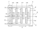
- FIG. FIG. 3 is a diagram showing the structure of the recording unit 9 of the printer 100.
- FIG. 4 is a diagram showing the structure of the recording heads 17a to 17c constituting the line heads 11C to 11K of the recording section 9 of the printer 100. As shown in FIG.
- the recording unit 9 includes a head housing 10 and line heads 11C, 11M, 11Y, and 11K held by the head housing 10, as shown in FIGS.
- the line heads 11C to 11K have a height such that a predetermined interval (eg, 1 mm) is formed with respect to the conveying surface of the first conveying belt 8 stretched over a plurality of rollers including the driving roller 6 and the driven roller 7. , and a plurality of (here, three) recording heads 17a to 17c are arranged in a zigzag pattern along the paper width direction (vertical direction in FIG. 2).
- the line heads 11C to 11K have a recording area wider than the width of the paper P to be conveyed. (hereinafter simply referred to as ink) is ejected.
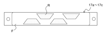
- FIG. 5 is a diagram of the recording heads 17a to 17c of the printer 100 viewed from the ink ejection surface F side.
- nozzle regions R are provided on the ink ejection surfaces F of the recording heads 17a to 17c.
- a large number of openings (not shown) are arranged at the ends of the discharge nozzles 18 (see FIG. 2).
- a water-repellent film (not shown) is formed on the ink ejection surface F.
- the recording heads 17a to 17c have the same shape and configuration, the recording heads 17a to 17c are shown as one figure in FIGS.
- the recording heads 17a to 17c constituting the line heads 11C to 11K four colors (cyan, magenta, yellow and black) of ink stored in ink tanks (not shown) are supplied to the line heads 11C to 11K. Supplied per color.
- Each of the recording heads 17a to 17c ejects ink from the ejection nozzles 18 (see FIG. 2) toward the paper P that is transported while being adsorbed and held on the transport surface of the first transport belt 8, according to the image data received from the external computer. to dispense.
- a color image is formed on the paper P on the first conveying belt 8 by superimposing the four colors of cyan, magenta, yellow, and black inks.
- the ejection nozzles 18 (see FIG. 2) of all the recording heads 17a to 17c are turned off. In between operations, purging is executed to push out the ink with high viscosity from the ejection nozzles 18 of the recording heads 17a to 17c whose ink ejection amount is equal to or less than the specified value, to prepare for the next printing operation.
- cap units 30 can be attached to the recording heads 17a to 17c.
- the cap unit 30 is connected to a unit horizontal movement mechanism 65 (cap movement mechanism) and a unit lifting mechanism 66 (cap movement mechanism).
- the unit horizontal movement mechanism 65 and the unit elevating mechanism 66 move the cap unit 30 in the horizontal direction (in this case, along the paper transport direction) and in the vertical direction, so that the cap portion 30b, which will be described later, moves between the recording heads 17a to 17c.
- the cap unit 30 can be moved between a first position separated from the ink ejection surface F and a second position attached to the ink ejection surface F. As shown in FIG.
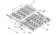
- FIG. 6 is a diagram showing the structures of the recording unit 9, cap unit 30, maintenance unit 19, etc. of the printer 100.
- FIG. 7 is a diagram showing the structure of the cap unit 30 of the printer 100.
- FIG. 8 and 9 are perspective views showing the structure of the carriage 71 of the printer 100.
- FIG. 8 shows a state in which the support arm 74 is laid down
- FIG. 9 shows a state in which the support arm 74 is raised.
- the cap unit 30 includes a cap tray 30a, a cap portion 30b, and height direction positioning projections 30c.
- the cap tray 30a is a rectangular plate made of sheet metal.
- the cap portion 30b is arranged on the upper surface of the cap tray 30a at a position corresponding to the arrangement (staggered arrangement) of the recording heads 17a to 17c.
- the cap portion 30b is formed in a concave shape so that the ink ejection surface F enters the inside of the cap portion 30b when it is attached to the recording heads 17a to 17c.
- the ink ejection surface F and the bottom surface of the cap portion 30b are brought into contact with each other.
- Four height direction positioning projections 30c are provided on the upper surface of the cap tray 30a.
- the cap unit 30 is moved by the unit horizontal movement mechanism 65 to a position (position shown in FIG. 12) directly below the recording section 9 and facing the recording section 9 in the vertical direction, and horizontally (in the direction of the arrow A) from the facing position. It is possible to reciprocate between the retracted retracted position (the position in FIG. 6).
- the cap unit 30 is moved by the unit elevating mechanism 66 to the facing position (first position) and the contact position (first position) where the bottom surface of each cap portion 30b contacts the ink ejection surfaces F of the recording heads 17a to 17c. 2 position).
- the cap portion 30b is mounted in contact with the recording heads 17a to 17c to cap (seal) the recording heads 17a to 17c.
- the height direction positioning protrusion 30c is positioned at a predetermined height.
- the tip comes into contact with the head housing 10 of the recording section 9 .
- the upward movement of the cap unit 30 is restricted by the contact between the height direction positioning projection 30c and the head housing 10, and the contact state between the cap portion 30b and the ink ejection surface F is maintained constant.
- the unit horizontal movement mechanism 65 is provided below the recording section 9 .
- the unit horizontal movement mechanism 65 includes guide rails 60 a and 60 b, guide plates 61 a and 61 b, and a drive motor 72 .
- the guide rails 60a and 60b are arranged below the recording section 9 along both ends of the recording section 9 in the paper width direction (arrow CC' direction) so as to be parallel to the paper transport direction (arrow A direction). ing.
- the guide plates 61a, 61b are fixed to the lower ends of the guide rails 60a, 60b.
- the side edges of the cap unit 30 are supported by the lower ends of the guide plates 61a and 61b.
- a carriage 71 is slidably supported by the guide rails 60a and 60b in the paper transport direction.
- the carriage 71 is a box-shaped body composed of a bottom surface 77 and a pair of side walls 78.
- a pair of side wall portions 78 are formed to rise upward from both edges of the bottom surface 77 in the paper width direction.
- the pair of side wall portions 78 are opposed to each other in the paper width direction.
- the maintenance unit 19 is mounted on the bottom surface 77 of the carriage 71 (see FIG. 6).
- a rack tooth 71a extending in the sheet conveying direction is formed at the upper end of one side (here, the arrow C side) of the pair of side walls 78 .
- the drive motor 72 is arranged outside the guide rail 60b (arrow C side) with respect to the paper width direction.
- the drive motor 72 has a cover member 73 and a gear train (not shown).
- a cover member 73 is provided to cover the drive motor 72 .
- the gear train consists of an output shaft (not shown) of the drive motor 72 and a plurality of gears (not shown) engaged with the output shaft.
- the gear train is arranged so as to mesh with the rack teeth 71a.
- the gear train transmits the rotational driving force of the drive motor 72 to the carriage 71 via the rack teeth 71a.
- the rotational drive force of the drive motor 72 is transmitted to the carriage 71 as a drive force along the paper transport direction by a cam mechanism of a gear train and rack teeth 71a. That is, when the drive motor 72 rotates forward, the gear train rotates, and the maintenance unit 19 together with the carriage 71 moves in one of the paper transport directions (the arrow A' direction here). Conversely, when the driving motor 72 rotates in the reverse direction, the maintenance unit 19 moves along with the carriage 71 in the other paper transport direction (here, the arrow A direction).
- the maintenance unit 19 (carriage 71) has a position directly below the recording section 9 and facing the recording section 9 in the vertical direction (position in FIG. 12, first position), and a horizontal direction from the facing position (here, paper It is possible to reciprocate between the retracted position (the position in FIG. 6) retracted in the transport direction).
- the maintenance unit 19 is configured to move upward at the facing position to perform a wiping operation (an operation of wiping off the ink discharged onto the ink ejection surface F).
- the maintenance unit 19 (carriage 71) can reciprocate integrally with the cap unit 30, or can separate from the cap unit 30 and reciprocate separately.
- the carriage 71 and the cap unit 30 are provided with an engagement mechanism (not shown) that engages each other when they move together and separates each other when they move separately. can.
- the unit elevating mechanism 66 includes a support arm 74, a wipe elevating motor 76, a rotating shaft 75, and a guide groove 71b.
- the support arms 74 are provided at four corners of the carriage 71 .
- the support arm 74 supports the maintenance unit 19 from the bottom side and can swing (stand up or lie down).
- Support arms 74 adjacent to each other in the paper transport direction (arrow A-A' direction) are connected via a rotating shaft 75 .
- the support arm 74 swings between an upright state and a laid-down state as the rotating shaft 75 rotates.
- the wipe lift motor 76 is provided outside the carriage 71 (here, downstream in the paper transport direction).
- the wipe lift motor 76 has an output shaft and a gear train (not shown) composed of a plurality of gears.
- a gear train of the wipe lift motor 76 is engaged with the rotating shaft 75 (not shown).
- the rotating shaft 75 rotates forward from the state in which the support arm 74 is laid down (the state shown in FIG. 8), the support arm 74 swings to the upright state (the state shown in FIG. 9).
- the maintenance unit 19 is raised and lowered by the ups and downs of the support arm 74 .
- the guide groove 71b extends along the vertical direction on the inner surface (paper width direction) of the other of the pair of side wall portions 78 of the carriage 71 (here, on the arrow C' side). is formed on the inner surface of the At both ends of the maintenance unit 19 in the paper width direction, guide projections (not shown) projecting toward the inside of the guide groove 71b are provided.
- the guide protrusion abuts against the inner surface of the guide groove 71b, thereby guiding the maintenance unit 19 in the vertical direction while restricting movement in the paper transport direction.
- the first belt conveying section 5 When attaching the cap unit 30 to the recording heads 17a to 17c, first, as indicated by the white arrow in FIG. 10, the first belt conveying section 5 is lowered. Then, as shown in FIG. 12, with the cap unit 30 placed on the maintenance unit 19, the unit horizontal movement mechanism 65 moves the maintenance unit 19 and the cap unit 30 from the retracted position to the opposing position. After that, the maintenance unit 19 and the cap unit 30 are lifted by the unit elevating mechanism 66, and the cap unit 30 (cap portion 30b) is attached to the recording heads 17a to 17c.
- FIG. 13 is a block diagram showing an example of the control path of the printer 100 of this embodiment.
- the printer 100 further includes a control device 110 (control unit), an operation panel 27 (input unit, display unit), a storage unit 28, and a communication unit 29 in addition to the above configuration.
- the control device 110 includes, for example, a CPU (Central Processing Unit) and a memory. Specifically, the control device 110 includes a main control section 110a, a print completion time setting section 110b, a paper supply control section 110c, a maintenance control section 110d, and a defect detection section 110e.
- a CPU Central Processing Unit
- the control device 110 includes a main control section 110a, a print completion time setting section 110b, a paper supply control section 110c, a maintenance control section 110d, and a defect detection section 110e.
- the main control unit 110 a controls the operation of each unit of the printer 100 .
- the main control unit 110 a also has a counting unit that counts time and a time setting unit that sets the time (neither of which is shown), and stores time and time settings in the storage unit 28 .
- the main controller 110a counts the time between ink ejections after the ink is ejected until the next ink ejection.
- the print completion time setting unit 110b sets the theoretical print completion time at the start of printing.
- the theoretical print completion time is the printing time based on the size information of the paper P and the number of printed sheets input from the operation panel 27 (to be described later), calibration for performing density correction, and suppression of ink discharge failures of the line heads 11C to 11K. , maintenance time required for purging by the maintenance unit 19, etc., and user response time required for replenishment of paper P, switching of paper feed trays, and the like.
- the paper supply control unit 110c controls the registration roller pair 13 and the paper feeders 3a-3b. For example, the paper supply control unit 110c controls the transport timing of the succeeding paper P by controlling the registration roller pair 13 based on the detection timing of the trailing edge of the paper P by the CIS 21 .
- the maintenance control unit 110d performs control to forcibly push out the ink from the ink ejection nozzles 18 of the recording heads constituting each of the line heads 11C to 11K to execute the above-described purge.
- the maintenance control section 110d also controls driving of the unit horizontal movement mechanism 65 and the unit lifting mechanism 66 described above.
- the maintenance control section 110d performs an operation of attaching the cap unit 30 to the recording heads 17a to 17c (hereinafter referred to as a "cap operation").
- the timing at which the time between ink ejections reaches a predetermined time is referred to as the cap closing timing.
- the maintenance control unit 110d determines that the paper P is staying around the recording unit 9 based on the detection result of the paper detection sensor 50 when it is time to close the cap, the maintenance control unit 110d stops performing the capping operation. do.
- the unit horizontal movement mechanism 65 and the unit lifting mechanism 66 are cut off from the power supply. Therefore, when the body cover 51 is in the open state, the maintenance control unit 110d stops performing the capping operation even when the closing timing comes.
- the defect detection unit 110e can detect a movement hindrance factor from the state of each device and each sensor of the printer 100.
- a movement-inhibiting factor is a factor that inhibits movement of the cap unit 30 to the second position.
- movement obstruction factors include a paper jam of the paper P around the recording unit 9 described above, the main body cover 51 being in an open state, and the like.
- the main control unit 110a determines whether to suspend the capping operation based on the status of each device of the printer 100. including cases where
- the operation panel 27 is an operation unit (input unit) for receiving various setting inputs.
- the user can operate the operation panel 27 to input the size information of the paper P to be set in the paper feed cassettes 2a and 2b or the manual paper feed tray 2c.
- the user can also operate the operation panel 27 to input the number of sheets of paper P to be printed and to instruct the start of a print job.
- the operation panel 27 also functions as a notification device (display unit) that notifies the operation status of the printer 100 .
- the storage unit 28 is a memory that stores the operation program of the control device 110 and various information, and includes ROM (Read Only Memory), RAM (Random Access Memory), nonvolatile memory, and the like. There is Information set by the operation panel 27 is stored in the storage unit 28 .
- the storage unit 28 has a cap time storage unit 26 and a defect storage unit 24.
- the cap closing time is stored in the cap time storage unit 26 .
- the cap closing time is the accumulated time during which the cap unit 30 is attached to the recording heads 17a to 17c. More specifically, the cumulative time from when the cap unit 30 is attached to the recording heads 17a to 17c at the cap closing timing to when the cap unit 30 is separated from the recording heads 17a to 17c for the next ink ejection. is.
- the defect storage unit 24 stores information about various defects that have occurred in the printer 100 (hereinafter referred to as "defect information").
- the defect information includes the above-described movement hindrance factor, the occurrence time and number of occurrences of the movement hindrance factor, the cap-unmovable time, which will be described later, and the difference value between the cap closed and the cap-unmovable time.
- the cap-movable time is the time from the occurrence of the movement-obstructing factor to the removal of the movement-obstructing factor when the above-mentioned movement-obstructing factor occurs at the cap closing timing.
- An example of cap movement disabled time is as follows. As described above, when the main body cover 51 is opened, the defect detection unit 110 e detects the occurrence of a movement hindrance factor based on the detection result of the cover opening/closing detection sensor 53 . When the body cover 51 is closed, based on the detection result of the cover open/close detection sensor 53, the defect detection unit 110e detects that the movement hindrance factor has been eliminated.
- the time from the timing when the generation of the movement hindrance factor is detected (the timing when the opening of the body cover 51 is detected) to the timing when the removal of the movement hindrance factor is detected (the timing when the body cover 51 is closed). , which is an example of cap-movable time.
- the defect detection unit 110e detects a movement hindrance factor based on the detection result of the paper detection sensor 50. to detect the occurrence of The time from the timing at which the generation of the cause of movement obstruction is detected (the timing at which paper jam of paper P is detected) to the timing at which the removal of the movement obstruction factor is detected (the timing at which the paper P is removed) is the cap movement. This is an example of unavailable time.
- the main control unit 110a calculates a difference value by subtracting the cap-movable time from the cap closing time. This difference value is stored in the defect storage unit 24 as defect information. This difference value means the time during which the cap unit 30 could not be attached due to the generation of the movement hindrance factor with respect to the time during which the cap unit 30 was originally attached to the recording heads 17a to 17c.
- the main control unit 110a can execute the measurement mode.
- the user directly inputs an instruction to start and end the measurement mode from the operation panel 27 .
- the main control unit 110a stores defect information including the movement obstruction factor in the defect storage unit 24 when the movement obstruction factor occurs during execution of the measurement mode.
- the trouble information stored in the storage section 28 is displayed on the operation panel 27 .
- the measurement mode can be started when the printing process is started or midway, and can be ended when the printing process is halfway or when the printing process ends. It is also possible to set in advance so that the measurement mode is executed in a predetermined section. Details of an example of control in the measurement mode will be described later.
- the communication unit 29 is a communication interface for transmitting and receiving information with an external device (for example, a personal computer (PC)).
- an external device for example, a personal computer (PC)
- PC personal computer
- the image data and print command are input to the printer 100 via the communication unit 29 .
- an image can be recorded on the paper P by controlling the recording heads 17a to 17c to eject ink based on the image data by the main controller 110a.
- FIG. 14 is a flow chart showing an example of a control flow in measurement mode.
- the main control unit 110a determines whether or not an image forming command has been input from a host device such as a personal computer (step S1). If the image forming command is not input (No in step S1), the image forming standby state is continued until the image forming command is input.
- step S1 When an image formation command is input (Yes in step S1), the main control unit 110a starts image formation and determines whether execution of the measurement mode is input (step S2). If execution of the measurement mode is not input (No in step S2), image formation is continued, and the standby state of the measurement mode continues until execution of the measurement mode is input.
- step S4 When execution of the measurement mode is input (Yes in step S2), the defect information stored in the defect storage unit 24 is deleted (step S3). Next, it is determined whether or not a movement hindrance factor has occurred during image formation (step S4). If a movement-obstructing factor occurs (Yes in step S4), defect information on the movement-obstructing factor (information including the movement-obstructing factor, the time when the cap-moving-obstructing factor occurred, and the difference value between the cap-closed time and the cap-immovable time) is stored in the defect storage unit 24 (step S5). If no movement hindering factor has occurred (No in step S4), step S5 is skipped and the process proceeds to step S6.
- step S6 it is determined whether or not the termination of the measurement mode has been input.
- the defect information stored in the defect storage unit 24 is displayed on the operation panel 27 (step S7), and control of the measurement mode is terminated. If the end of the measurement mode has not been input (No in step S6), the process returns to step S4, and steps S4 to S6 are repeated until the end of the measurement mode is input.
- the cap-movable time and the difference value are accumulated and stored in the time that has already been stored. Specifically, after storing the cap-movable time in step S5, the end of the measurement mode is not input (No in step S6), and the cap-movable time due to another movement hindrance factor is stored again in step S5. In this case, the main control unit 110a calculates an accumulated time by adding the previously stored cap movement time to the later cap movement disabled time, and stores the accumulated time in the defect storage unit 24. FIG. Further, the main control unit 110a calculates the difference value as the accumulated time of the cap movement prohibited time, and stores it in the defect storage unit 24. FIG.
- the printer 100 can detect the occurrence of movement-obstructing factors and store defect information in the defect storage unit 24 . Then, the user can perform maintenance of the printer 100 based on the trouble information stored in the trouble storage unit 24, or review the operation method of the printer 100, the print processing settings, and the like. As a result, it is possible to suppress the occurrence of movement hindrance factors, and to reduce the frequency of purging. Therefore, it is possible to provide the printer 100 capable of suppressing a decrease in productivity.
- the printer 100 when the printer 100 is used for so-called business use in which thousands of sheets are printed in one printing process, the user who operates the printer 100 should be a skilled person who has extensive knowledge of the printing process. There are many. If the user is a skilled user, he/she may want to know whether or not movement obstruction factors occur in the print process during a part of the time period of the long print process. On the other hand, the printer 100 according to the above embodiment can execute and end the measurement mode by operating the operation panel 27 as described above. Therefore, the user can grasp the defect information related to the movement hindrance factor that occurred in an arbitrary section (time period).
- the defect information stored in the defect storage unit 24 includes the cap-movable time.
- the printer 100 stores the cap closing time in the storage unit 28, calculates the difference value between the cap closing time and the cap unmovable time, and stores it as defect information in the defect storage unit. 24.
- the user can grasp the time during which the cap unit 30 could not be attached due to movement impeding factors, compared to the time during which the cap unit 30 was originally attached to the recording heads 17a to 17c.
- the user can perform maintenance of the printer 100, etc., by assuming the dryness of the ejection nozzles 18 and the timing of purging, thereby suppressing a decrease in productivity.
- the defect information includes the number of occurrences of factors that impede movement. For this reason, the user needs to know the number of occurrences of factors that impede movement, and take appropriate measures (such as revising the operating method and print settings of the printer 100 and performing maintenance on the printer 100) to suppress the occurrence of factors that impede movement. It can be carried out. Further, as described above, the defect information includes the time when the movement hindering factor occurred. Therefore, it is possible to grasp the timing of occurrence of the movement hindrance factor.
- the present invention is not limited to the above embodiments, and various modifications are possible without departing from the scope of the present invention.
- the movement hindrance factor may be pre-stored in the storage unit 28, which will be described later, or may be determined by the defect detection unit 110e or the main control unit 110a based on the operating state of the printer 100.
- an optical photosensor can be used as the cover open/close detection sensor 53
- a mechanical button or switch capable of detecting the open/closed state of the main body cover 51 for example, may be used.
- the paper detection sensor 50 detects the presence or absence of the paper P between the recording unit 9 and the first transport belt 8, but instead of the paper detection sensor 50, the CIS 21 detects the recording unit 9 and the first transport belt. It is also possible to employ a configuration for detecting the presence or absence of the paper P between the rollers 8 and 8 .
- the present invention can be used for an image forming apparatus that forms an image on a recording medium by an inkjet recording method, and that attaches a cap to the recording head between printing processes.
- the user can grasp the information (defect information) about the factor (movement hindrance factor) that prevents the cap from being attached to the print head when the frequency of purging or the amount of ink used for purging increases. be able to.
- the factor movement hindrance factor
Landscapes
- Ink Jet (AREA)
Abstract
Description
Claims (8)
- 記録媒体を搬送する搬送部と、
インクを吐出するインク吐出面を有し、前記搬送部によって搬送される前記記録媒体に前記インク吐出面から前記インクを吐出して印刷処理を行う記録ヘッドと、
前記インク吐出面に対し着脱可能であり、前記インク吐出面を保護するキャップ部材と、
前記キャップ部材を、前記インク吐出面から離間した第1の位置と前記インク吐出面に装着された第2の位置とに移動可能なキャップ移動機構と、
前記インク吐出面から前記インクが吐出された後、次に前記インクが吐出されるまでの間に所定時間経過したキャップ閉鎖タイミングで、前記キャップ部材を前記第1の位置から前記第2の位置に移動させるように前記キャップ移動機構を制御する制御部と、
を備えるインクジェット記録装置において、
前記キャップ部材の前記第2の位置への移動を阻害する移動阻害要因の発生を検出可能な不具合検出部と、
前記移動阻害要因を含む不具合情報を記憶可能な記憶部と、
を備え、
前記制御部は、前記不具合検出部の検出結果に基づいて前記不具合情報を前記記憶部に記憶する測定モードを実行可能であることを特徴とするインクジェット記録装置。 - 前記測定モードの実行および終了を入力する入力部と、
前記不具合情報を表示する表示部と、
を備え、
前記制御部は、前記測定モードの実行が入力されると、前記記憶部に記憶された前記不具合情報を削除し、その後の前記印刷処理中に生じた前記不具合情報を前記記憶部に記憶し、前記測定モードの終了が入力されると、前記記憶部に記憶された前記不具合情報を表示することを特徴とする請求項1に記載のインクジェット記録装置。 - 前記搬送部の、前記記録媒体が前記インク吐出面と対向する対向位置に、前記記録媒体が存在するか否かを検知可能な記録媒体検知センサーを備え、
前記キャップ閉鎖タイミングで前記記録媒体が前記対向位置に存在する場合、前記不具合検出部は前記記録媒体検知センサーの検知結果を前記移動阻害要因として検出することを特徴とする請求項1に記載のインクジェット記録装置。 - 前記記録ヘッドおよび前記キャップ移動機構が内部に設けられた装置本体と、
前記装置本体に設けられ、前記装置本体の内部を開放または閉鎖する開閉カバーと、
前記開閉カバーが開放した状態を検知可能なカバー開閉検知センサーと、
を備え、
前記不具合検出部は、前記閉鎖タイミングで前記カバー開閉検知センサーが前記開閉カバーの開放状態を検知した場合、前記カバー開閉検知センサーの検知結果を前記移動阻害要因として検出することを特徴とする請求項1に記載のインクジェット記録装置。 - 前記制御部は、前記キャップ閉鎖タイミングにおいて前記移動阻害要因が発生した場合、前記移動阻害要因発生から前記移動阻害要因が解消されるまでの時間をキャップ移動不可時間として前記記憶部に記憶し、
前記不具合情報は、前記キャップ移動不可時間を含むことを特徴とする請求項1に記載のインクジェット記録装置。 - 前記制御部は、前記キャップ閉鎖タイミングからその後の前記インク吐出面から前記インクを吐出するタイミングまでのキャップ閉鎖時間を前記記憶部に記憶し、前記キャップ閉鎖時間と前記キャップ移動不可時間との差分値を算出して前記記憶部に記憶し、
前記不具合情報は、前記差分値を含むことを特徴とする請求項5に記載のインクジェット記録装置。 - 前記制御部は、前記キャップ閉鎖タイミングにおいて前記移動阻害要因が発生した回数であるキャップ移動不可回数を記憶し、
前記不具合情報は、前記キャップ移動不可回数を含むことを特徴とする請求項1に記載のインクジェット記録装置。 - 前記制御部は、前記移動阻害要因の発生時刻である不具合発生時刻を前記記憶部に記憶し、
前記不具合情報は、前記不具合発生時刻を含むことを特徴とする請求項1に記載のインクジェット記録装置。
Priority Applications (2)
| Application Number | Priority Date | Filing Date | Title |
|---|---|---|---|
| US18/713,855 US20240351336A1 (en) | 2021-11-30 | 2022-11-24 | Ink-jet recording apparatus |
| JP2023564917A JP7690998B2 (ja) | 2021-11-30 | 2022-11-24 | インクジェット記録装置 |
Applications Claiming Priority (2)
| Application Number | Priority Date | Filing Date | Title |
|---|---|---|---|
| JP2021193973 | 2021-11-30 | ||
| JP2021-193973 | 2021-11-30 |
Publications (1)
| Publication Number | Publication Date |
|---|---|
| WO2023100738A1 true WO2023100738A1 (ja) | 2023-06-08 |
Family
ID=86612088
Family Applications (1)
| Application Number | Title | Priority Date | Filing Date |
|---|---|---|---|
| PCT/JP2022/043342 Ceased WO2023100738A1 (ja) | 2021-11-30 | 2022-11-24 | インクジェット記録装置 |
Country Status (3)
| Country | Link |
|---|---|
| US (1) | US20240351336A1 (ja) |
| JP (1) | JP7690998B2 (ja) |
| WO (1) | WO2023100738A1 (ja) |
Citations (6)
| Publication number | Priority date | Publication date | Assignee | Title |
|---|---|---|---|---|
| WO1996015908A1 (en) * | 1994-11-21 | 1996-05-30 | Techniku B.V. | Cleaning and sealing station for a printing head |
| JP2011136468A (ja) * | 2009-12-28 | 2011-07-14 | Kyocera Mita Corp | インクジェット記録装置 |
| JP2014144585A (ja) * | 2013-01-29 | 2014-08-14 | Kyocera Document Solutions Inc | キャップ及びインクジェット記録装置 |
| JP2018001477A (ja) * | 2016-06-29 | 2018-01-11 | セイコーエプソン株式会社 | 印刷装置、及び印刷方法 |
| JP2020066126A (ja) * | 2018-10-22 | 2020-04-30 | 京セラドキュメントソリューションズ株式会社 | 記録ヘッドのメンテナンス装置およびそれを備えたインクジェット記録装置 |
| JP2020142485A (ja) * | 2019-03-08 | 2020-09-10 | 京セラドキュメントソリューションズ株式会社 | 記録ヘッドのメンテナンス装置およびそれを備えたインクジェット記録装置 |
Family Cites Families (4)
| Publication number | Priority date | Publication date | Assignee | Title |
|---|---|---|---|---|
| JP2942031B2 (ja) * | 1991-09-30 | 1999-08-30 | キヤノン株式会社 | インクジェット記録装置 |
| JP2014000679A (ja) * | 2012-06-15 | 2014-01-09 | Seiko Epson Corp | プリンターおよびその制御方法 |
| EP3496949B1 (en) * | 2016-10-05 | 2022-11-30 | Hewlett-Packard Development Company, L.P. | Fluid ejection device capping |
| JP7107097B2 (ja) * | 2018-08-29 | 2022-07-27 | セイコーエプソン株式会社 | 液滴吐出装置及び液滴吐出装置のメンテナンス方法 |
-
2022
- 2022-11-24 US US18/713,855 patent/US20240351336A1/en active Pending
- 2022-11-24 WO PCT/JP2022/043342 patent/WO2023100738A1/ja not_active Ceased
- 2022-11-24 JP JP2023564917A patent/JP7690998B2/ja active Active
Patent Citations (6)
| Publication number | Priority date | Publication date | Assignee | Title |
|---|---|---|---|---|
| WO1996015908A1 (en) * | 1994-11-21 | 1996-05-30 | Techniku B.V. | Cleaning and sealing station for a printing head |
| JP2011136468A (ja) * | 2009-12-28 | 2011-07-14 | Kyocera Mita Corp | インクジェット記録装置 |
| JP2014144585A (ja) * | 2013-01-29 | 2014-08-14 | Kyocera Document Solutions Inc | キャップ及びインクジェット記録装置 |
| JP2018001477A (ja) * | 2016-06-29 | 2018-01-11 | セイコーエプソン株式会社 | 印刷装置、及び印刷方法 |
| JP2020066126A (ja) * | 2018-10-22 | 2020-04-30 | 京セラドキュメントソリューションズ株式会社 | 記録ヘッドのメンテナンス装置およびそれを備えたインクジェット記録装置 |
| JP2020142485A (ja) * | 2019-03-08 | 2020-09-10 | 京セラドキュメントソリューションズ株式会社 | 記録ヘッドのメンテナンス装置およびそれを備えたインクジェット記録装置 |
Also Published As
| Publication number | Publication date |
|---|---|
| JPWO2023100738A1 (ja) | 2023-06-08 |
| US20240351336A1 (en) | 2024-10-24 |
| JP7690998B2 (ja) | 2025-06-11 |
Similar Documents
| Publication | Publication Date | Title |
|---|---|---|
| JP6938252B2 (ja) | 液体吐出装置 | |
| JP2012166449A (ja) | 画像形成装置および防塵用カバー | |
| JP2002103638A (ja) | インクジェットプリンタのラインヘッドクリーニング装置 | |
| JP5570052B2 (ja) | インクジェット記録装置 | |
| JP5703267B2 (ja) | インクジェット記録装置 | |
| JP2010221644A (ja) | 画像記録装置 | |
| JP7396012B2 (ja) | インクジェット記録装置 | |
| JP2009096099A (ja) | 画像記録装置 | |
| US11945237B2 (en) | Inkjet recording device | |
| JP2015048181A (ja) | インクジェット記録装置 | |
| JP5040506B2 (ja) | インクジェット記録装置 | |
| US20210331497A1 (en) | Inkjet recording device | |
| JP7690998B2 (ja) | インクジェット記録装置 | |
| JP7319138B2 (ja) | インクジェット印刷装置 | |
| JP7163738B2 (ja) | 記録装置及び記録装置の制御方法 | |
| JP5031289B2 (ja) | 画像記録装置 | |
| US20060197983A1 (en) | Method of controlling liquid ejection | |
| JP7484358B2 (ja) | インクジェット記録装置 | |
| JP2011005735A (ja) | 画像記録装置及び画像記録装置の初期化制御方法 | |
| JP2022148027A (ja) | インクジェット記録装置 | |
| JP4497013B2 (ja) | 被記録媒体の媒体給送装置及び該媒体給送装置を備えた記録装置と液体噴射装置 | |
| JP2006076079A (ja) | インクジェット式プリンタ | |
| US11789391B2 (en) | Image forming apparatus | |
| JP2017109364A (ja) | 印刷装置の制御方法および印刷装置 | |
| JP2017121705A (ja) | 印刷装置の制御方法および印刷装置 |
Legal Events
| Date | Code | Title | Description |
|---|---|---|---|
| 121 | Ep: the epo has been informed by wipo that ep was designated in this application |
Ref document number: 22901171 Country of ref document: EP Kind code of ref document: A1 |
|
| ENP | Entry into the national phase |
Ref document number: 2023564917 Country of ref document: JP Kind code of ref document: A |
|
| WWE | Wipo information: entry into national phase |
Ref document number: 18713855 Country of ref document: US |
|
| NENP | Non-entry into the national phase |
Ref country code: DE |
|
| 122 | Ep: pct application non-entry in european phase |
Ref document number: 22901171 Country of ref document: EP Kind code of ref document: A1 |