WO2023100647A1 - 二次電池 - Google Patents
二次電池 Download PDFInfo
- Publication number
- WO2023100647A1 WO2023100647A1 PCT/JP2022/042444 JP2022042444W WO2023100647A1 WO 2023100647 A1 WO2023100647 A1 WO 2023100647A1 JP 2022042444 W JP2022042444 W JP 2022042444W WO 2023100647 A1 WO2023100647 A1 WO 2023100647A1
- Authority
- WO
- WIPO (PCT)
- Prior art keywords
- resistant layer
- heat
- separator
- width direction
- outermost peripheral
- Prior art date
- Legal status (The legal status is an assumption and is not a legal conclusion. Google has not performed a legal analysis and makes no representation as to the accuracy of the status listed.)
- Ceased
Links
Images



Classifications
-
- H—ELECTRICITY
- H01—ELECTRIC ELEMENTS
- H01M—PROCESSES OR MEANS, e.g. BATTERIES, FOR THE DIRECT CONVERSION OF CHEMICAL ENERGY INTO ELECTRICAL ENERGY
- H01M10/00—Secondary cells; Manufacture thereof
- H01M10/05—Accumulators with non-aqueous electrolyte
- H01M10/058—Construction or manufacture
- H01M10/0587—Construction or manufacture of accumulators having only wound construction elements, i.e. wound positive electrodes, wound negative electrodes and wound separators
-
- H—ELECTRICITY
- H01—ELECTRIC ELEMENTS
- H01M—PROCESSES OR MEANS, e.g. BATTERIES, FOR THE DIRECT CONVERSION OF CHEMICAL ENERGY INTO ELECTRICAL ENERGY
- H01M50/00—Constructional details or processes of manufacture of the non-active parts of electrochemical cells other than fuel cells, e.g. hybrid cells
- H01M50/40—Separators; Membranes; Diaphragms; Spacing elements inside cells
- H01M50/489—Separators, membranes, diaphragms or spacing elements inside the cells, characterised by their physical properties, e.g. swelling degree, hydrophilicity or shut down properties
-
- H—ELECTRICITY
- H01—ELECTRIC ELEMENTS
- H01M—PROCESSES OR MEANS, e.g. BATTERIES, FOR THE DIRECT CONVERSION OF CHEMICAL ENERGY INTO ELECTRICAL ENERGY
- H01M10/00—Secondary cells; Manufacture thereof
- H01M10/04—Construction or manufacture in general
- H01M10/0431—Cells with wound or folded electrodes
-
- H—ELECTRICITY
- H01—ELECTRIC ELEMENTS
- H01M—PROCESSES OR MEANS, e.g. BATTERIES, FOR THE DIRECT CONVERSION OF CHEMICAL ENERGY INTO ELECTRICAL ENERGY
- H01M10/00—Secondary cells; Manufacture thereof
- H01M10/05—Accumulators with non-aqueous electrolyte
- H01M10/052—Li-accumulators
-
- H—ELECTRICITY
- H01—ELECTRIC ELEMENTS
- H01M—PROCESSES OR MEANS, e.g. BATTERIES, FOR THE DIRECT CONVERSION OF CHEMICAL ENERGY INTO ELECTRICAL ENERGY
- H01M50/00—Constructional details or processes of manufacture of the non-active parts of electrochemical cells other than fuel cells, e.g. hybrid cells
- H01M50/40—Separators; Membranes; Diaphragms; Spacing elements inside cells
- H01M50/409—Separators, membranes or diaphragms characterised by the material
-
- H—ELECTRICITY
- H01—ELECTRIC ELEMENTS
- H01M—PROCESSES OR MEANS, e.g. BATTERIES, FOR THE DIRECT CONVERSION OF CHEMICAL ENERGY INTO ELECTRICAL ENERGY
- H01M50/00—Constructional details or processes of manufacture of the non-active parts of electrochemical cells other than fuel cells, e.g. hybrid cells
- H01M50/40—Separators; Membranes; Diaphragms; Spacing elements inside cells
- H01M50/409—Separators, membranes or diaphragms characterised by the material
- H01M50/449—Separators, membranes or diaphragms characterised by the material having a layered structure
-
- H—ELECTRICITY
- H01—ELECTRIC ELEMENTS
- H01M—PROCESSES OR MEANS, e.g. BATTERIES, FOR THE DIRECT CONVERSION OF CHEMICAL ENERGY INTO ELECTRICAL ENERGY
- H01M50/00—Constructional details or processes of manufacture of the non-active parts of electrochemical cells other than fuel cells, e.g. hybrid cells
- H01M50/40—Separators; Membranes; Diaphragms; Spacing elements inside cells
- H01M50/409—Separators, membranes or diaphragms characterised by the material
- H01M50/449—Separators, membranes or diaphragms characterised by the material having a layered structure
- H01M50/451—Separators, membranes or diaphragms characterised by the material having a layered structure comprising layers of only organic material and layers containing inorganic material
-
- H—ELECTRICITY
- H01—ELECTRIC ELEMENTS
- H01M—PROCESSES OR MEANS, e.g. BATTERIES, FOR THE DIRECT CONVERSION OF CHEMICAL ENERGY INTO ELECTRICAL ENERGY
- H01M50/00—Constructional details or processes of manufacture of the non-active parts of electrochemical cells other than fuel cells, e.g. hybrid cells
- H01M50/40—Separators; Membranes; Diaphragms; Spacing elements inside cells
- H01M50/463—Separators, membranes or diaphragms characterised by their shape
-
- H—ELECTRICITY
- H01—ELECTRIC ELEMENTS
- H01M—PROCESSES OR MEANS, e.g. BATTERIES, FOR THE DIRECT CONVERSION OF CHEMICAL ENERGY INTO ELECTRICAL ENERGY
- H01M50/00—Constructional details or processes of manufacture of the non-active parts of electrochemical cells other than fuel cells, e.g. hybrid cells
- H01M50/50—Current conducting connections for cells or batteries
- H01M50/572—Means for preventing undesired use or discharge
- H01M50/584—Means for preventing undesired use or discharge for preventing incorrect connections inside or outside the batteries
- H01M50/59—Means for preventing undesired use or discharge for preventing incorrect connections inside or outside the batteries characterised by the protection means
- H01M50/595—Tapes
-
- H—ELECTRICITY
- H01—ELECTRIC ELEMENTS
- H01M—PROCESSES OR MEANS, e.g. BATTERIES, FOR THE DIRECT CONVERSION OF CHEMICAL ENERGY INTO ELECTRICAL ENERGY
- H01M4/00—Electrodes
- H01M4/02—Electrodes composed of, or comprising, active material
- H01M2004/026—Electrodes composed of, or comprising, active material characterised by the polarity
- H01M2004/027—Negative electrodes
-
- H—ELECTRICITY
- H01—ELECTRIC ELEMENTS
- H01M—PROCESSES OR MEANS, e.g. BATTERIES, FOR THE DIRECT CONVERSION OF CHEMICAL ENERGY INTO ELECTRICAL ENERGY
- H01M4/00—Electrodes
- H01M4/02—Electrodes composed of, or comprising, active material
- H01M2004/026—Electrodes composed of, or comprising, active material characterised by the polarity
- H01M2004/028—Positive electrodes
-
- Y—GENERAL TAGGING OF NEW TECHNOLOGICAL DEVELOPMENTS; GENERAL TAGGING OF CROSS-SECTIONAL TECHNOLOGIES SPANNING OVER SEVERAL SECTIONS OF THE IPC; TECHNICAL SUBJECTS COVERED BY FORMER USPC CROSS-REFERENCE ART COLLECTIONS [XRACs] AND DIGESTS
- Y02—TECHNOLOGIES OR APPLICATIONS FOR MITIGATION OR ADAPTATION AGAINST CLIMATE CHANGE
- Y02E—REDUCTION OF GREENHOUSE GAS [GHG] EMISSIONS, RELATED TO ENERGY GENERATION, TRANSMISSION OR DISTRIBUTION
- Y02E60/00—Enabling technologies; Technologies with a potential or indirect contribution to GHG emissions mitigation
- Y02E60/10—Energy storage using batteries
-
- Y—GENERAL TAGGING OF NEW TECHNOLOGICAL DEVELOPMENTS; GENERAL TAGGING OF CROSS-SECTIONAL TECHNOLOGIES SPANNING OVER SEVERAL SECTIONS OF THE IPC; TECHNICAL SUBJECTS COVERED BY FORMER USPC CROSS-REFERENCE ART COLLECTIONS [XRACs] AND DIGESTS
- Y02—TECHNOLOGIES OR APPLICATIONS FOR MITIGATION OR ADAPTATION AGAINST CLIMATE CHANGE
- Y02P—CLIMATE CHANGE MITIGATION TECHNOLOGIES IN THE PRODUCTION OR PROCESSING OF GOODS
- Y02P70/00—Climate change mitigation technologies in the production process for final industrial or consumer products
- Y02P70/50—Manufacturing or production processes characterised by the final manufactured product
Definitions
- the present disclosure relates to secondary batteries.
- a non-aqueous electrolyte secondary battery having a wound electrode assembly in which a positive electrode and a negative electrode are wound with a separator interposed has been widely used.
- Patent Literatures 1 and 2 disclose a non-aqueous electrolyte secondary battery using a separator having a heat-resistant layer.
- a tape is wound around the outermost peripheral surface of the electrode body in order to fix the members constituting the electrode body.
- the member (negative electrode, positive electrode, or separator) forming the outermost peripheral surface of the electrode body may be cut at the edge of the tape.
- a cut member on the outermost peripheral surface of the electrode assembly poses a risk of short circuit. Even if the member forming the outermost peripheral surface of the electrode body is not cut, for example, the risk of short circuit may increase due to expansion of the negative electrode at the center of the electrode body due to uneven reaction of the electrode body.
- an object of the present disclosure is to provide a secondary battery that can suppress member breakage on the outermost peripheral surface of the electrode body due to repeated charging and discharging and further reduce the risk of short circuit.
- a secondary battery includes a wound electrode body in which a positive electrode and a negative electrode are wound with a separator interposed therebetween;
- a non-aqueous electrolyte secondary battery comprising an outermost peripheral tape attached so as to straddle the separator, wherein the separator has a base material layer and a heat-resistant layer disposed on at least one surface of the base material layer.
- the heat-resistant layer includes a first end heat-resistant layer having a predetermined width from one end in the width direction of the separator along the winding axis direction of the electrode body to the center side, and a heat-resistant layer extending along the winding axis direction of the electrode body.
- a second end heat-resistant layer having a predetermined width on the center side from the other end in the width direction of the separator, and a central heat-resistant layer sandwiched between the first heat-resistant layer and the second heat-resistant layer,
- the outermost tape has a first outermost tape arranged on one end side in the winding axial direction of the electrode assembly and a second outermost circumference tape arranged on the other end side in the winding axial direction of the electrode assembly.
- At least part of the first outermost peripheral tape faces the first end heat resistant layer
- at least part of the second outermost peripheral tape faces the second end heat resistant layer
- the thickness (Y1) of one end heat-resistant layer and the thickness (Y2) of the second end heat-resistant layer are thinner than the thickness (Z) of the central heat-resistant layer and thicker than 0.001 mm
- the separator The ratio (A1/W) of the length (A1) from one end in the width direction of the separator to the center side end in the width direction of the first outermost peripheral tape with respect to the length (W) in the width direction of the separator, and the separator
- the ratio (A2/W) of the length (A2) from the other end in the width direction of the separator to the center side end in the width direction of the second outermost peripheral tape with respect to the length (W) in the width direction of It is characterized by being 0.25 or less.
- FIG. 1 is a schematic cross-sectional view of a non-aqueous electrolyte secondary battery that is an example of an embodiment
- FIG. 1 is a schematic perspective view showing an example of a wound electrode body
- FIG. 3 is a schematic plan view showing an example of a separator before being wound around an electrode body
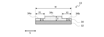
- 4 is a schematic cross-sectional view of the separator taken along line L1-L1 in FIG. 3
- FIG. 3 is a partial schematic cross-sectional view for explaining a state in which the separator of the wound electrode assembly shown in FIG. 2 and the outermost peripheral tape face each other;
- a non-aqueous electrolyte secondary battery will be described below as an example of the secondary battery of the present disclosure.
- the secondary battery of the present disclosure is not limited to the following non-aqueous electrolyte secondary batteries, and can be applied to various secondary batteries without departing from the technical idea of the present disclosure.
- FIG. 1 is a schematic cross-sectional view of a non-aqueous electrolyte secondary battery that is an example of an embodiment.
- the non-aqueous electrolyte secondary battery 10 shown in FIG. It has insulating plates 18 and 19 arranged and a battery case 15 that accommodates the above members.
- the battery case 15 is composed of a bottomed cylindrical case body 16 and a sealing member 17 that closes the opening of the case body 16 .
- Examples of the battery case 15 include a cylindrical or rectangular metal case, a resin case formed by laminating resin sheets (so-called laminate type), and the like.
- the case body 16 is, for example, a bottomed cylindrical metal container.
- a gasket 28 is provided between the case body 16 and the sealing member 17 to ensure hermeticity inside the battery.
- the case main body 16 has an overhanging portion 22 that supports the sealing member 17, for example, a portion of the side surface overhanging inward.
- the protruding portion 22 is preferably annularly formed along the circumferential direction of the case body 16 and supports the sealing member 17 on the upper surface thereof.
- the sealing body 17 has a structure in which a filter 23, a lower valve body 24, an insulating member 25, an upper valve body 26, and a cap 27 are layered in order from the electrode body 14 side.
- Each member constituting the sealing member 17 has, for example, a disk shape or a ring shape, and each member except for the insulating member 25 is electrically connected to each other.
- the lower valve body 24 and the upper valve body 26 are connected to each other at their central portions, and an insulating member 25 is interposed between their peripheral edge portions.
- the lower valve body 24 deforms and breaks so as to push the upper valve body 26 upward toward the cap 27, thereby breaking the lower valve body 24 and the upper valve.
- the current path between bodies 26 is interrupted.
- the upper valve body 26 is broken and the gas is discharged from the opening of the cap 27 .
- the positive electrode lead 20 attached to the positive electrode 11 extends through the through hole of the insulating plate 18 toward the sealing member 17, and the negative electrode lead 21 attached to the negative electrode 12 is insulated. It extends to the bottom side of the case body 16 through the outside of the plate 19 .
- the positive electrode lead 20 is connected to the lower surface of the filter 23, which is the bottom plate of the sealing member 17, by welding or the like, and the cap 27, which is the top plate of the sealing member 17 electrically connected to the filter 23, serves as a positive electrode terminal.
- the negative lead 21 is connected to the inner surface of the bottom of the case body 16 by welding or the like, and the case body 16 serves as a negative terminal.
- FIG. 2 is a schematic perspective view showing an example of a wound electrode body.
- the electrode body 14 is formed by interposing the separator 13 between the positive electrode 11 and the negative electrode 12 and winding these members.
- a winding end portion 14 a of the electrode body 14 is present on the outermost peripheral surface of the electrode body 14 .
- a winding end portion 14a of the electrode body 14 is a winding end portion of the members (positive electrode 11, negative electrode 12, separator 13) of the electrode body 14 on the outermost peripheral surface of the electrode body 14.
- FIG. For example, in order to bring the negative electrode current collector that constitutes the negative electrode 12 into contact with the case body 16, the negative electrode 12 (substantially the negative electrode current collector) is extended by one turn or more from the winding end portion of the positive electrode 11 and the separator 13.
- the outermost peripheral surface of the electrode body 14 is wound and used as the negative electrode 12 . Further, for example, when the winding end portions of the positive electrode 11, the negative electrode 12, and the separator 13 are located at different positions on the outermost peripheral surface of the electrode body 14, the respective winding end portions are located at the winding end portion 14a of the electrode body 14. (That is, there are three winding end portions 14a on the outermost peripheral surface of the electrode body 14).
- a first outermost tape 30a and a second outermost tape 30b are attached to the outermost peripheral surface of the electrode body 14 so as to straddle the winding end portion 14a of the electrode body 14. have.
- the first outermost peripheral tape 30a is arranged on one end side of the electrode body 14 in the winding axial direction (arrow S shown in FIG. 2).
- the first outermost peripheral tape 30a may be arranged with a predetermined gap from one end of the electrode assembly 14 in the winding axial direction, or may be arranged at one end of the electrode assembly 14 in the winding axial direction. They may be arranged close to each other without leaving a gap.
- the second outermost tape 30b is arranged on the other end side of the electrode body 14 in the winding axial direction. As shown in FIG. 2, the second outermost peripheral tape 30b may be arranged with a predetermined gap from the other end of the electrode assembly 14 in the winding axial direction, or may be arranged at one end of the electrode assembly 14 in the winding axial direction. , and may be arranged without leaving a gap.
- the outermost peripheral tapes (30a, 30b) are referred to, both the first outermost peripheral tape 30a and the second outermost peripheral tape 30b are referred to.
- the members constituting the electrode body 14 are fixed. That is, the wound state of the positive electrode 11, the negative electrode 12, and the separator 13 is maintained without unraveling.
- the outermost peripheral tapes (30a, 30b) wrap around the outermost peripheral surface of the electrode assembly 14 one or more times.
- conventionally known tapes used for wound electrode bodies are applied for the outermost peripheral tapes (30a, 30b).
- FIG. 3 is a schematic plan view of the separator before it is wound around the electrode body
- FIG. 4 is a schematic cross-sectional view of the separator taken along line L1-L1 in FIG.
- An arrow S shown in the drawing indicates the winding axial direction of the electrode assembly 14, and an arrow R orthogonal to the arrow S indicates the winding direction of the separator 13 (that is, the winding direction of the members constituting the electrode assembly 14).
- the separator 13 has a base layer 32 and a heat-resistant layer 34 arranged on one side of the base layer 32 .
- the heat-resistant layer 34 is not limited to being arranged on one side of the base layer 32 , and may be arranged on both sides of the base layer 32 .
- the heat-resistant layer 34 is used as the positive electrode from the viewpoint of improving the charge-discharge cycle characteristics and safety of the battery. It is preferable to stack the separator 13 and the positive electrode 11 so as to face the separator 11 .
- the separator 13 may be designed to be larger in width and length than the positive electrode 11 and the negative electrode 12 in order to prevent short-circuiting between the positive and negative electrodes. In this case, when the positive electrode 11 and the negative electrode 12 are stacked on the separator 13 when the electrode body 14 is manufactured, the separator 13 protrudes from the positive electrode 11 and the negative electrode 12 .
- the heat-resistant layer 34 includes a first end heat-resistant layer 34a having a predetermined width from one end of the heat-resistant layer 34 in the width direction along the winding axis direction of the electrode body 14 toward the center, A second end heat-resistant layer 34b having a predetermined width from the other end of the heat-resistant layer 34 in the width direction along the winding axis direction of the electrode body 14 to the center side, a first end heat-resistant layer 34a, and a second end heat-resistant layer 34a. It has a central heat-resistant layer 34c sandwiched between it and the layer 34b.
- FIG. 5 is a partial schematic cross-sectional view for explaining the opposing state of the separator of the wound electrode body shown in FIG. 2 and the outermost peripheral tape.
- the wound-type electrode body 14 is in a state in which the positive electrode 11, the negative electrode 12, and the separator 13 are stacked in a direction perpendicular to the winding axial direction (arrow S) of the electrode body 14.
- FIG. Only one of the laminated separators 13 and the outermost tapes (30a, 30b) adhered to the outermost outer surface of the electrode assembly 14 are shown for illustration.
- At least part of the first outermost peripheral tape 30 a faces the first end heat-resistant layer 34 a of the separator 13
- at least part of the second outermost peripheral tape 30 b faces the second edge of the separator 13 . It faces the edge heat-resistant layer 34b.
- at least part of the outermost tapes (30a, 30b) faces the first end heat-resistant layer 34a or the second end heat-resistant layer 34b means that the first outermost tape 30a is projected onto the separator 13.
- At least part of the projection area overlaps at least part of the first end heat-resistant layer 34a, and at least part of the projection area when the second outermost peripheral tape 30b is projected onto the separator 13 is the second end heat-resistant layer 34b. It means a state that overlaps with at least part of
- the thickness (Y1) of the first end heat-resistant layer 34a and the thickness (Y2) of the second end heat-resistant layer 34b are each equal to the thickness (Z) of the central heat-resistant layer 34c. Thinner and thicker than 0.001 mm. Further, referring to FIG. 5, the length (W) of the separator 13 in the width direction along the winding axis direction (arrow S) of the electrode assembly 14 is extended from one end of the separator 13 in the width direction to the first outermost peripheral tape 30a.
- the ratio (A2/W) of the length (A2) from the other end of the second outermost peripheral tape 30b to the center side end in the width direction is 0.25 or less.
- the members (the positive electrode 11, the negative electrode 12, or the separator 13) forming the outermost peripheral surface of the electrode body 14 are suppressed from breaking at the ends of the outermost peripheral tapes (30a, 30b). . Further, expansion of the negative electrode at the central portion of the electrode body due to uneven reaction of the electrode body 14 is suppressed. And from these things, a short-circuit risk is reduced.
- the thickness (Y1) of the first end heat-resistant layer 34a and the thickness (Y2) of the second end heat-resistant layer 34b are set to 0.001 mm or less, for example, separator shrinkage due to deterioration in heat resistance of the separator 13 may cause an internal short circuit.
- the ratio (Z/Y2) of the thickness (Z) of the heat-resistant layer 34c is preferably 1.4 or more.
- the thickness (Z) of the central heat-resistant layer 34c is preferably 0.0045 mm or more.
- the heat resistance of the separator 13 can be improved more than when it is less than 0.0045 mm. Further, if the expansion of the negative electrode in the central portion of the electrode assembly increases due to uneven electrode reaction, the risk of short circuit may increase. , leading to a reduction in the risk of a short circuit due to expansion of the negative electrode at the center of the electrode body.
- At least part of the first outermost peripheral tape 30a faces the first end heat resistant layer 34a, and at least part of the second outermost peripheral tape 30b faces the second end heat resistant layer 34b.
- the entire first outermost peripheral tape 30a faces the first end heat-resistant layer 34a, and the entire second outermost peripheral tape 30b faces the second end heat-resistant layer 34b.
- the entirety of the outermost peripheral tapes (30a, 30b) facing the first end heat-resistant layer 34a or the second end heat-resistant layer 34b means that the projection area of the first outermost peripheral tape 30a projected onto the separator 13 is A state in which the entire area overlaps at least a portion of the first end heat-resistant layer 34a, and a state in which the entire projection area when the second outermost peripheral tape 30b is projected onto the separator 13 overlaps at least a portion of the second end heat-resistant layer 34b.
- the ratio (X2/W) of the predetermined width (X2) of the second end heat-resistant layer 34b to the length (W) in the width direction is preferably 0.25 or less, and 0.10 or more. It is more preferably 0.25 or less.
- the heat resistance of the separator 13 may be improved, for example, compared to when it exceeds 0.25.
- the base material layer 32 is composed of, for example, a porous base material, specifically a microporous thin film, a woven fabric, a nonwoven fabric, or the like.
- the material of the base material layer 32 is not particularly limited, but examples thereof include polyolefins such as polyethylene, polypropylene, copolymers of polyethylene and ⁇ -olefin, acrylic resins, polystyrene, polyesters, and cellulose.
- the base material layer 32 may have a single layer structure or a laminated structure. Although the thickness of the base layer 32 is not particularly limited, it is preferably in the range of 3 ⁇ m to 20 ⁇ m, for example.
- the average pore size of the base material layer 32 is, for example, preferably in the range of 0.02 ⁇ m to 0.5 ⁇ m, more preferably in the range of 0.03 ⁇ m to 0.3 ⁇ m.
- the average pore diameter of the base material layer 32 is measured using a perm porometer (manufactured by Seika Sangyo Co., Ltd.) capable of measuring pore diameters by the bubble point method (JIS K3832, ASTM F316-86).
- the heat-resistant layer 34 contains, for example, filler and resin. By including the filler in the heat-resistant layer 34, for example, the heat-resistant layer 34 can be given an effect of suppressing thermal shrinkage.
- the melting point or thermal softening point of the filler is, for example, preferably 150° C. or higher, more preferably 200° C. or higher.
- fillers include metal oxide particles, metal nitride particles, metal fluoride particles and metal carbide particles.
- metal oxide particles include aluminum oxide, titanium oxide, magnesium oxide, zirconium oxide, nickel oxide, silicon oxide, and manganese oxide.
- metal nitride particles include titanium nitride, boron nitride, aluminum nitride, magnesium nitride, and silicon nitride.
- metal fluoride particles include aluminum fluoride, lithium fluoride, sodium fluoride, magnesium fluoride, calcium fluoride, barium fluoride, and the like.
- metal carbide particles include silicon carbide, boron carbide, titanium carbide, and tungsten carbide.
- the fillers include porous aluminosilicates such as zeolite (M2 /nO.Al2O3.xSiO2.yH2O , M is a metal element, x ⁇ 2 , y ⁇ 0 ) , talc ( Mg3 Layered silicates such as Si 4 O 10 (OH) 2 ), minerals such as barium titanate (BaTiO 3 ), strontium titanate (SrTiO 3 ), and the like may also be used. In addition, these may be used individually by 1 type, and may use 2 or more types together.
- the BET specific surface area of the filler is not particularly limited, but is preferably in the range of 1 m 2 /g to 20 m 2 /g, more preferably in the range of 3 m 2 /g to 15 m 2 /g.
- the average particle size of the filler is not particularly limited, it is preferably in the range of 0.1 ⁇ m to 5 ⁇ m, more preferably in the range of 0.2 ⁇ m to 1 ⁇ m.
- the content of the filler is, for example, preferably in the range of 70% by mass or more and 95% by mass or less with respect to the total mass of the heat-resistant layer 34.
- the resin preferably has a function as a binder that bonds the fillers together and the fillers and the base material layer.
- the resin include fluorine-based resins such as polyvinylidene fluoride (PVDF) and polytetrafluoroethylene (PTFE), polyimide-based resins, acrylic resins, and polyolefin-based resins. These may be used alone or in combination of two or more.
- the content of the resin is preferably, for example, in the range of 5% by mass to 15% by mass with respect to the total mass of the heat-resistant layer 34.
- a heat-resistant layer slurry containing a filler and a resin is prepared. After applying the slurry to the entire surface of the substrate layer 32 , the slurry is dried to form the heat-resistant layer 34 on the entire surface of the substrate layer 32 . Further, the above slurry is applied to the central portion of the heat-resistant layer 34 in the width direction along the longitudinal direction of the heat-resistant layer 34, and then dried.
- a central heat-resistant layer 34c having a thickness at the central portion in the width direction of the heat-resistant layer 34, and a first end heat-resistant layer 34a and a second end heat-resistant layer having thin thickness at both ends of the heat-resistant layer 34 in the width direction are formed.
- a separator 13 having 34b formed on the substrate layer 32 is obtained.
- the positive electrode 11 has, for example, a positive electrode current collector and a positive electrode active material layer provided on the positive electrode current collector.
- a positive electrode current collector for example, a foil of a metal such as aluminum that is stable in the potential range of the positive electrode, a film in which the metal is arranged on the surface layer, or the like can be used.
- the positive electrode active material layer contains a positive electrode active material, and also contains a conductive material and a binder.
- Examples of the positive electrode active material include lithium transition metal composite oxides, and specific examples include lithium cobalt oxide, lithium manganate, lithium nickel oxide, lithium nickel manganese composite oxide, lithium nickel cobalt composite oxide, and the like. Al, Ti, Zr, Nb, B, W, Mg, Mo, etc. may be added to these lithium transition metal composite oxides.
- carbon powder such as carbon black, acetylene black, ketjen black, and graphite may be used singly or in combination of two or more.
- binders include fluorine-based resins such as polytetrafluoroethylene (PTFE) and polyvinylidene fluoride (PVdF), polyacrylonitrile (PAN), polyimide-based resins, acrylic-based resins, and polyolefin-based resins. These may be used alone or in combination of two or more.
- fluorine-based resins such as polytetrafluoroethylene (PTFE) and polyvinylidene fluoride (PVdF), polyacrylonitrile (PAN), polyimide-based resins, acrylic-based resins, and polyolefin-based resins. These may be used alone or in combination of two or more.
- the negative electrode 12 has, for example, a negative electrode current collector and a negative electrode active material layer provided on the negative electrode current collector.
- a negative electrode current collector for example, a foil of a metal such as copper that is stable in the potential range of the negative electrode, a film having the metal on the surface layer, or the like can be used.
- the negative electrode active material layer contains a negative electrode active material and also contains a binder and the like.
- a carbon material capable of intercalating and deintercalating lithium ions can be used, and in addition to graphite, non-graphitizable carbon, graphitizable carbon, fibrous carbon, coke, carbon black, etc. can be used. can be done. Furthermore, as non-carbon materials, silicon, tin, and alloys and oxides based on these can be used.
- binders include fluorine-based resins, PAN, polyimide-based resins, acrylic resins, polyolefin-based resins, styrene-butadiene rubber (SBR), nitrile-butadiene rubber (NBR), carboxymethylcellulose (CMC) or salts thereof, poly Acrylic acid (PAA) or its salt, polyvinyl alcohol (PVA), etc. are mentioned. These may be used alone or in combination of two or more.
- a non-aqueous electrolyte includes a non-aqueous solvent and an electrolyte salt dissolved in the non-aqueous solvent.
- non-aqueous solvents examples include esters, ethers, nitriles such as acetonitrile, amides such as dimethylformamide, and mixed solvents of two or more thereof.
- the non-aqueous solvent may contain a halogen-substituted product obtained by substituting at least part of the hydrogen atoms of these solvents with halogen atoms such as fluorine.
- esters examples include cyclic carbonates such as ethylene carbonate (EC), propylene carbonate (PC) and butylene carbonate, dimethyl carbonate (DMC), ethyl methyl carbonate (EMC), diethyl carbonate (DEC), methyl propyl carbonate. , Ethyl propyl carbonate, methyl isopropyl carbonate and other chain carbonates, ⁇ -butyrolactone, ⁇ -valerolactone and other cyclic carboxylic acid esters, methyl acetate, ethyl acetate, propyl acetate, methyl propionate (MP), ethyl propionate, etc. and chain carboxylic acid esters of.
- cyclic carbonates such as ethylene carbonate (EC), propylene carbonate (PC) and butylene carbonate, dimethyl carbonate (DMC), ethyl methyl carbonate (EMC), diethyl carbonate (DEC), methyl propyl carbonate.
- ethers examples include 1,3-dioxolane, 4-methyl-1,3-dioxolane, tetrahydrofuran, 2-methyltetrahydrofuran, propylene oxide, 1,2-butylene oxide, 1,3-dioxane, 1,4 -dioxane, 1,3,5-trioxane, furan, 2-methylfuran, 1,8-cineol, cyclic ethers such as crown ether, 1,2-dimethoxyethane, diethyl ether, dipropyl ether, diisopropyl ether, dibutyl ether , dihexyl ether, ethyl vinyl ether, butyl vinyl ether, methyl phenyl ether, ethyl phenyl ether, butyl phenyl ether, pentyl phenyl ether, methoxytoluene, benzyl ethyl ether, diphenyl ether, cycl
- a fluorinated cyclic carbonate such as fluoroethylene carbonate (FEC), a fluorinated chain carbonate, a fluorinated chain carboxylate such as methyl fluoropropionate (FMP), and the like.
- FEC fluoroethylene carbonate
- FMP fluorinated chain carboxylate
- FEC fluoroethylene carbonate
- FMP fluorinated chain carboxylate
- the electrolyte salt is a lithium salt.
- lithium salts include LiBF4 , LiClO4 , LiPF6 , LiAsF6 , LiSbF6 , LiAlCl4 , LiSCN, LiCF3SO3 , LiCF3CO2 , Li(P( C2O4 ) F4 ) , LiPF 6-x (C n F 2n+1 ) x (1 ⁇ x ⁇ 6, n is 1 or 2), LiB 10 Cl 10 , LiCl, LiBr, LiI, lithium chloroborane, lithium lower aliphatic carboxylate, Li 2 B 4O7 , borates such as Li (B( C2O4 ) F2 ), LiN( SO2CF3 ) 2 , LiN( C1F2l + 1SO2 )( CmF2m + 1SO2 ) ⁇ l , where m is an integer of 1 or more ⁇ .
- Lithium salts may be used singly or in combination. Of these, it is preferable to use LiPF 6 from the viewpoint of ion conductivity, electrochemical stability, and the like.
- the lithium salt concentration is preferably 0.8 to 1.8 mol per 1 L of solvent.
- ⁇ Example 1> 100 parts by mass of a positive electrode active material represented by LiNi 0.91 Co 0.04 Al 0.05 O 2 , 1.0 parts by mass of acetylene black as a conductive material, and 0.9 parts by mass of polyvinylidene fluoride as a binder Parts by mass were mixed in a solvent of N-methyl-2-pyrrolidone to prepare a positive electrode mixture slurry.
- the positive electrode mixture slurry was applied to both sides of an aluminum foil having a thickness of 20 ⁇ m, dried, and then rolled by a roll press. After that, it was cut to a predetermined size. Thus, a positive electrode was obtained in which positive electrode active material layers were formed on both surfaces of the positive electrode current collector.
- a negative electrode 80 parts by mass of graphite powder, 20 parts by mass of Si oxide, 1 part by mass of carboxymethyl cellulose (CMC), and 1 part by mass of styrene-butadiene rubber are mixed, and the mixture is dispersed in water to prepare a negative electrode mixture slurry. prepared.
- the negative electrode mixture slurry was applied to both sides of a copper foil having a thickness of 10 ⁇ m, dried, and then rolled by a roll press. The obtained member was cut into a predetermined size. Thus, a negative electrode having negative electrode active material layers formed on both sides of the negative electrode current collector was obtained.
- the sheet of the polyolefin resin composition was washed with water, dried, and stretched by a tenter stretching machine to obtain a porous polyolefin resin composition sheet. This was used as a substrate layer.
- the thickness of the base material layer was 0.014 mm.
- a predetermined amount of heat-resistant layer slurry was applied to the entire surface of the substrate layer, and the aramid resin was precipitated in an atmosphere of 60°C temperature and 70% humidity. After that, the precipitated aramid resin was washed with water and dried. As a result, a heat-resistant layer containing aramid resin and alumina was formed on the entire surface of the substrate layer.
- the heat-resistant layer slurry was applied onto the heat-resistant layer in a predetermined width along the longitudinal direction of the heat-resistant layer at the central portion in the width direction of the heat-resistant layer. After that, the aramid resin was precipitated, washed with water, and dried in the same manner as described above. The obtained member was slit at a width of 62 mm.
- the end heat-resistant layers (the first end heat-resistant layer and the second end heat-resistant layer) formed at both ends in the width direction of the heat-resistant layer, the first end heat-resistant layer and the second end heat-resistant layer A separator was obtained in which a central heat-resistant layer sandwiched between the layers was formed on the base material layer.
- Example 1 the thickness (Y1) of the first end heat-resistant layer and the thickness (Y2) of the second end heat-resistant layer were each set to 0.0030 mm. Further, in Example 1, the thickness (Z) of the central heat-resistant layer was set to 0.0050 mm. In each example and each comparative example, (Y1) and (Y2) are designed to be the same. (Y).
- the ratio (X1/W) of the width length (X1) of the first end heat-resistant layer to the width length (W) of the separator and the second end heat-resistant layer to the width length (W) of the separator The ratio (X2/W) of the width to the length (X2) of each was set to 0.19.
- (X1/W) and (X2/W) are designed to be the same in both Examples and Comparative Examples, (X1/W) and (X2/W) ) is described as the ratio (X/W) of the width (X) of the edge heat-resistant layer to the width (W) of the separator.
- a positive electrode lead was attached to the positive electrode current collector, and a negative electrode lead was attached to the negative electrode current collector. Then, the separator was arranged between the positive electrode and the negative electrode so that the heat-resistant layer of the separator faced the positive electrode. After that, these were wound to produce a wound electrode body having the outermost peripheral surface of the electrode body as a negative electrode current collector. Then, a first outermost tape and a second outermost tape having a width of 9 mm were wrapped around one end side and the other end side of the outermost circumferential surface of the electrode body in the winding axial direction and attached to the electrode body.
- Example 1 the ratio (A1/W) of the length (A1) from one end in the width direction of the separator to the central end in the width direction of the first outermost peripheral tape with respect to the length (W) of the width of the separator was set to 0.19, and the entire first outermost peripheral tape was opposed to the first end heat-resistant layer.
- the ratio (A2/W) of the length (A2) from the other end of the separator in the width direction to the central end of the second outermost peripheral tape in the width direction with respect to the length (W) of the width of the separator is set to 0. .19, and the entire second outermost peripheral tape was opposed to the second end heat-resistant layer.
- (A1/W) and (A2/W) are designed to be the same in each example and each comparative example, (A1/W) and (A2/W) ) is described as the ratio (A/W) of the length (A) from the widthwise end of the separator to the widthwise central end of the outermost peripheral tape with respect to the widthwise length (W) of the separator.
- Example 2 a separator was produced in the same manner as in Example 1, except that the thickness (Y) of the edge heat-resistant layer was 0.0033 mm and the thickness (Z) of the central heat-resistant layer was 0.0047 mm. A water electrolyte secondary battery was produced.
- Example 3 the ratio (X/W) of the width length (X) of the edge heat-resistant layer to the width length (W) of the separator was set to 0.15, and part of the outermost peripheral tape was A non-aqueous electrolyte secondary battery was produced in the same manner as in Example 1, except that the separator was made to face the heat-resistant layer.
- Example 4 In Example 3, except that the ratio (X/W) of the width (X) of the edge heat-resistant layer to the width (W) of the separator was 0.29, A non-aqueous electrolyte secondary battery was produced in the same manner as in Example 1.
- Comparative Example 1 a predetermined amount of heat-resistant layer slurry was applied to the entire surface of the substrate layer in one step, and the thickness (Y) of the end heat-resistant layer was set to 0.0040 mm, and the thickness of the center heat-resistant layer was set to 0.0040 mm.
- a non-aqueous electrolyte secondary battery was produced in the same manner as in Example 1, except that the separator was produced with (Z) set to 0.0040 mm.
- Comparative Example 2 a predetermined amount of heat-resistant layer slurry was applied to the entire surface of the substrate layer in one step, and the thickness (Y) of the end heat-resistant layer was set to 0.0050 mm, and the thickness of the center heat-resistant layer was set to 0.0050 mm.
- a non-aqueous electrolyte secondary battery was produced in the same manner as in Example 1, except that the separator was produced with (Z) set to 0.0050 mm.
- Comparative Example 3 a predetermined amount of heat-resistant layer slurry was applied to the entire surface of the substrate layer in one step, and the thickness (Y) of the edge heat-resistant layer was set to 0.0030 mm, and the thickness of the center heat-resistant layer was set to 0.0030 mm.
- a non-aqueous electrolyte secondary battery was produced in the same manner as in Example 1, except that the separator was produced with (Z) set to 0.0030 mm.
- Comparative Example 4 a non-aqueous electrolyte secondary battery was produced in the same manner as in Example 1, except that a separator was produced in which the thickness (Y) of the edge heat-resistant layer was 0.0010 mm.
- Comparative Example 5 In Comparative Example 5, the positions of the first outermost peripheral tape and the second outermost peripheral tape were set to the central side in the winding axial direction of the electrode body, and from the end in the width direction of the separator with respect to the width (W) of the separator, A separator was produced in which the ratio (A/W) of the distance (A) to the central edge in the width direction of the outermost peripheral tape was set to 0.29. A non-aqueous electrolyte secondary battery was produced in the same manner as in Example 1, except that such a separator was used.
- the ratio (A/W) of the distance (A) from the widthwise end of the separator to the widthwise center side end of the outermost peripheral tape to the widthwise length (W) of the separator is 0.25 or less.
Landscapes
- Chemical & Material Sciences (AREA)
- Chemical Kinetics & Catalysis (AREA)
- Electrochemistry (AREA)
- General Chemical & Material Sciences (AREA)
- Engineering & Computer Science (AREA)
- Manufacturing & Machinery (AREA)
- Inorganic Chemistry (AREA)
- Secondary Cells (AREA)
- Cell Separators (AREA)
Priority Applications (3)
| Application Number | Priority Date | Filing Date | Title |
|---|---|---|---|
| CN202280077607.2A CN118285013A (zh) | 2021-11-30 | 2022-11-15 | 二次电池 |
| US18/708,470 US20250055140A1 (en) | 2021-11-30 | 2022-11-15 | Secondary battery |
| JP2023564856A JPWO2023100647A1 (https=) | 2021-11-30 | 2022-11-15 |
Applications Claiming Priority (2)
| Application Number | Priority Date | Filing Date | Title |
|---|---|---|---|
| JP2021194184 | 2021-11-30 | ||
| JP2021-194184 | 2021-11-30 |
Publications (1)
| Publication Number | Publication Date |
|---|---|
| WO2023100647A1 true WO2023100647A1 (ja) | 2023-06-08 |
Family
ID=86612033
Family Applications (1)
| Application Number | Title | Priority Date | Filing Date |
|---|---|---|---|
| PCT/JP2022/042444 Ceased WO2023100647A1 (ja) | 2021-11-30 | 2022-11-15 | 二次電池 |
Country Status (4)
| Country | Link |
|---|---|
| US (1) | US20250055140A1 (https=) |
| JP (1) | JPWO2023100647A1 (https=) |
| CN (1) | CN118285013A (https=) |
| WO (1) | WO2023100647A1 (https=) |
Citations (3)
| Publication number | Priority date | Publication date | Assignee | Title |
|---|---|---|---|---|
| JP2011034859A (ja) * | 2009-08-04 | 2011-02-17 | Hitachi Maxell Ltd | 電池用巻回電極体、電池およびその製造方法 |
| WO2019187755A1 (ja) * | 2018-03-27 | 2019-10-03 | 三洋電機株式会社 | 非水電解質二次電池 |
| WO2019244817A1 (ja) * | 2018-06-20 | 2019-12-26 | 三洋電機株式会社 | 非水電解質二次電池 |
-
2022
- 2022-11-15 JP JP2023564856A patent/JPWO2023100647A1/ja active Pending
- 2022-11-15 CN CN202280077607.2A patent/CN118285013A/zh active Pending
- 2022-11-15 US US18/708,470 patent/US20250055140A1/en active Pending
- 2022-11-15 WO PCT/JP2022/042444 patent/WO2023100647A1/ja not_active Ceased
Patent Citations (3)
| Publication number | Priority date | Publication date | Assignee | Title |
|---|---|---|---|---|
| JP2011034859A (ja) * | 2009-08-04 | 2011-02-17 | Hitachi Maxell Ltd | 電池用巻回電極体、電池およびその製造方法 |
| WO2019187755A1 (ja) * | 2018-03-27 | 2019-10-03 | 三洋電機株式会社 | 非水電解質二次電池 |
| WO2019244817A1 (ja) * | 2018-06-20 | 2019-12-26 | 三洋電機株式会社 | 非水電解質二次電池 |
Also Published As
| Publication number | Publication date |
|---|---|
| US20250055140A1 (en) | 2025-02-13 |
| JPWO2023100647A1 (https=) | 2023-06-08 |
| CN118285013A (zh) | 2024-07-02 |
Similar Documents
| Publication | Publication Date | Title |
|---|---|---|
| JP7212629B2 (ja) | リチウムイオン二次電池 | |
| CN111226340B (zh) | 非水电解质二次电池及其制造方法 | |
| WO2022209601A1 (ja) | リチウム二次電池 | |
| JP2016127000A (ja) | 非水電解質二次電池用正極及び非水電解質二次電池 | |
| WO2018221024A1 (ja) | 二次電池用正極、及び二次電池 | |
| KR20230047068A (ko) | 비수전해질 이차전지 | |
| JPWO2019107068A1 (ja) | 非水電解質二次電池 | |
| JP7361340B2 (ja) | 非水電解質二次電池用負極及び非水電解質二次電池 | |
| WO2023053626A1 (ja) | 非水電解質二次電池 | |
| JP7821191B2 (ja) | 非水電解質二次電池 | |
| JP7665440B2 (ja) | 非水電解質二次電池 | |
| CN112913049B (zh) | 非水电解质二次电池用正极及非水电解质二次电池 | |
| WO2023100647A1 (ja) | 二次電池 | |
| WO2023145506A1 (ja) | 非水電解質二次電池 | |
| CN119156738A (zh) | 非水电解质二次电池 | |
| JP7432850B2 (ja) | 正極及び二次電池 | |
| WO2023032490A1 (ja) | 非水電解質二次電池 | |
| WO2022158375A1 (ja) | 非水電解質二次電池 | |
| CN116601786A (zh) | 非水电解质二次电池用正极活性物质和非水电解质二次电池 | |
| JP7721526B2 (ja) | 非水電解質二次電池用セパレータ及び非水電解質二次電池 | |
| US20240055731A1 (en) | Non-aqueous electrolyte secondary battery | |
| US20240339727A1 (en) | Non-aqueous electrolyte secondary battery | |
| WO2025105319A1 (ja) | 非水電解質二次電池 | |
| WO2023276660A1 (ja) | 非水電解質二次電池 | |
| WO2023234099A1 (ja) | 非水電解質二次電池 |
Legal Events
| Date | Code | Title | Description |
|---|---|---|---|
| 121 | Ep: the epo has been informed by wipo that ep was designated in this application |
Ref document number: 22901080 Country of ref document: EP Kind code of ref document: A1 |
|
| WWE | Wipo information: entry into national phase |
Ref document number: 2023564856 Country of ref document: JP |
|
| WWE | Wipo information: entry into national phase |
Ref document number: 18708470 Country of ref document: US |
|
| WWE | Wipo information: entry into national phase |
Ref document number: 202280077607.2 Country of ref document: CN |
|
| NENP | Non-entry into the national phase |
Ref country code: DE |
|
| 122 | Ep: pct application non-entry in european phase |
Ref document number: 22901080 Country of ref document: EP Kind code of ref document: A1 |