WO2023100647A1 - Secondary battery - Google Patents
Secondary battery Download PDFInfo
- Publication number
- WO2023100647A1 WO2023100647A1 PCT/JP2022/042444 JP2022042444W WO2023100647A1 WO 2023100647 A1 WO2023100647 A1 WO 2023100647A1 JP 2022042444 W JP2022042444 W JP 2022042444W WO 2023100647 A1 WO2023100647 A1 WO 2023100647A1
- Authority
- WO
- WIPO (PCT)
- Prior art keywords
- resistant layer
- heat
- separator
- width direction
- outermost peripheral
- Prior art date
Links
- 230000002093 peripheral effect Effects 0.000 claims abstract description 76
- 238000004804 winding Methods 0.000 claims description 36
- 239000011255 nonaqueous electrolyte Substances 0.000 claims description 28
- 238000000034 method Methods 0.000 claims description 3
- 239000010410 layer Substances 0.000 description 157
- 230000000052 comparative effect Effects 0.000 description 17
- 239000000758 substrate Substances 0.000 description 17
- 229920005989 resin Polymers 0.000 description 16
- 239000011347 resin Substances 0.000 description 16
- -1 polyethylene Polymers 0.000 description 15
- 239000000463 material Substances 0.000 description 14
- 239000002002 slurry Substances 0.000 description 14
- 238000007789 sealing Methods 0.000 description 12
- 239000000945 filler Substances 0.000 description 11
- 229910052751 metal Inorganic materials 0.000 description 11
- 239000002184 metal Substances 0.000 description 11
- 239000002245 particle Substances 0.000 description 11
- 229920005672 polyolefin resin Polymers 0.000 description 8
- OKTJSMMVPCPJKN-UHFFFAOYSA-N Carbon Chemical compound [C] OKTJSMMVPCPJKN-UHFFFAOYSA-N 0.000 description 7
- 229920003235 aromatic polyamide Polymers 0.000 description 7
- SECXISVLQFMRJM-UHFFFAOYSA-N N-Methylpyrrolidone Chemical compound CN1CCCC1=O SECXISVLQFMRJM-UHFFFAOYSA-N 0.000 description 6
- 239000011230 binding agent Substances 0.000 description 6
- 238000007599 discharging Methods 0.000 description 6
- 239000000203 mixture Substances 0.000 description 6
- 239000007774 positive electrode material Substances 0.000 description 6
- SBLRHMKNNHXPHG-UHFFFAOYSA-N 4-fluoro-1,3-dioxolan-2-one Chemical compound FC1COC(=O)O1 SBLRHMKNNHXPHG-UHFFFAOYSA-N 0.000 description 5
- 239000002033 PVDF binder Substances 0.000 description 5
- 238000007600 charging Methods 0.000 description 5
- 239000007773 negative electrode material Substances 0.000 description 5
- 229920002981 polyvinylidene fluoride Polymers 0.000 description 5
- 239000011342 resin composition Substances 0.000 description 5
- XLYOFNOQVPJJNP-UHFFFAOYSA-N water Substances O XLYOFNOQVPJJNP-UHFFFAOYSA-N 0.000 description 5
- VTYYLEPIZMXCLO-UHFFFAOYSA-L Calcium carbonate Chemical compound [Ca+2].[O-]C([O-])=O VTYYLEPIZMXCLO-UHFFFAOYSA-L 0.000 description 4
- YCKRFDGAMUMZLT-UHFFFAOYSA-N Fluorine atom Chemical compound [F] YCKRFDGAMUMZLT-UHFFFAOYSA-N 0.000 description 4
- 239000003125 aqueous solvent Substances 0.000 description 4
- 239000004760 aramid Substances 0.000 description 4
- 229910052731 fluorine Inorganic materials 0.000 description 4
- 239000011737 fluorine Substances 0.000 description 4
- 229910003002 lithium salt Inorganic materials 0.000 description 4
- 159000000002 lithium salts Chemical group 0.000 description 4
- 229920001343 polytetrafluoroethylene Polymers 0.000 description 4
- 239000004810 polytetrafluoroethylene Substances 0.000 description 4
- 238000002360 preparation method Methods 0.000 description 4
- 150000003839 salts Chemical class 0.000 description 4
- UZKWTJUDCOPSNM-UHFFFAOYSA-N 1-ethenoxybutane Chemical compound CCCCOC=C UZKWTJUDCOPSNM-UHFFFAOYSA-N 0.000 description 3
- WEVYAHXRMPXWCK-UHFFFAOYSA-N Acetonitrile Chemical compound CC#N WEVYAHXRMPXWCK-UHFFFAOYSA-N 0.000 description 3
- 229920000178 Acrylic resin Polymers 0.000 description 3
- 239000004925 Acrylic resin Substances 0.000 description 3
- RTZKZFJDLAIYFH-UHFFFAOYSA-N Diethyl ether Chemical compound CCOCC RTZKZFJDLAIYFH-UHFFFAOYSA-N 0.000 description 3
- XEKOWRVHYACXOJ-UHFFFAOYSA-N Ethyl acetate Chemical compound CCOC(C)=O XEKOWRVHYACXOJ-UHFFFAOYSA-N 0.000 description 3
- ZMXDDKWLCZADIW-UHFFFAOYSA-N N,N-Dimethylformamide Chemical compound CN(C)C=O ZMXDDKWLCZADIW-UHFFFAOYSA-N 0.000 description 3
- 239000004642 Polyimide Substances 0.000 description 3
- 229910052782 aluminium Inorganic materials 0.000 description 3
- PNEYBMLMFCGWSK-UHFFFAOYSA-N aluminium oxide Inorganic materials [O-2].[O-2].[O-2].[Al+3].[Al+3] PNEYBMLMFCGWSK-UHFFFAOYSA-N 0.000 description 3
- QHIWVLPBUQWDMQ-UHFFFAOYSA-N butyl prop-2-enoate;methyl 2-methylprop-2-enoate;prop-2-enoic acid Chemical compound OC(=O)C=C.COC(=O)C(C)=C.CCCCOC(=O)C=C QHIWVLPBUQWDMQ-UHFFFAOYSA-N 0.000 description 3
- 239000004020 conductor Substances 0.000 description 3
- IEJIGPNLZYLLBP-UHFFFAOYSA-N dimethyl carbonate Chemical compound COC(=O)OC IEJIGPNLZYLLBP-UHFFFAOYSA-N 0.000 description 3
- 239000003792 electrolyte Substances 0.000 description 3
- 150000002170 ethers Chemical class 0.000 description 3
- 239000011888 foil Substances 0.000 description 3
- 229910052744 lithium Inorganic materials 0.000 description 3
- 229920002239 polyacrylonitrile Polymers 0.000 description 3
- 229920001721 polyimide Polymers 0.000 description 3
- 239000011148 porous material Substances 0.000 description 3
- 239000000243 solution Substances 0.000 description 3
- 239000002904 solvent Substances 0.000 description 3
- YLQBMQCUIZJEEH-UHFFFAOYSA-N tetrahydrofuran Natural products C=1C=COC=1 YLQBMQCUIZJEEH-UHFFFAOYSA-N 0.000 description 3
- DHKHKXVYLBGOIT-UHFFFAOYSA-N 1,1-Diethoxyethane Chemical compound CCOC(C)OCC DHKHKXVYLBGOIT-UHFFFAOYSA-N 0.000 description 2
- VQKFNUFAXTZWDK-UHFFFAOYSA-N 2-Methylfuran Chemical compound CC1=CC=CO1 VQKFNUFAXTZWDK-UHFFFAOYSA-N 0.000 description 2
- YEJRWHAVMIAJKC-UHFFFAOYSA-N 4-Butyrolactone Chemical compound O=C1CCCO1 YEJRWHAVMIAJKC-UHFFFAOYSA-N 0.000 description 2
- 229920002134 Carboxymethyl cellulose Polymers 0.000 description 2
- RYGMFSIKBFXOCR-UHFFFAOYSA-N Copper Chemical compound [Cu] RYGMFSIKBFXOCR-UHFFFAOYSA-N 0.000 description 2
- OIFBSDVPJOWBCH-UHFFFAOYSA-N Diethyl carbonate Chemical compound CCOC(=O)OCC OIFBSDVPJOWBCH-UHFFFAOYSA-N 0.000 description 2
- XTHFKEDIFFGKHM-UHFFFAOYSA-N Dimethoxyethane Chemical compound COCCOC XTHFKEDIFFGKHM-UHFFFAOYSA-N 0.000 description 2
- KMTRUDSVKNLOMY-UHFFFAOYSA-N Ethylene carbonate Chemical compound O=C1OCCO1 KMTRUDSVKNLOMY-UHFFFAOYSA-N 0.000 description 2
- VEXZGXHMUGYJMC-UHFFFAOYSA-N Hydrochloric acid Chemical compound Cl VEXZGXHMUGYJMC-UHFFFAOYSA-N 0.000 description 2
- 229910013870 LiPF 6 Inorganic materials 0.000 description 2
- RJUFJBKOKNCXHH-UHFFFAOYSA-N Methyl propionate Chemical compound CCC(=O)OC RJUFJBKOKNCXHH-UHFFFAOYSA-N 0.000 description 2
- 229920000459 Nitrile rubber Polymers 0.000 description 2
- 239000004698 Polyethylene Substances 0.000 description 2
- 239000004372 Polyvinyl alcohol Substances 0.000 description 2
- WYURNTSHIVDZCO-UHFFFAOYSA-N Tetrahydrofuran Chemical compound C1CCOC1 WYURNTSHIVDZCO-UHFFFAOYSA-N 0.000 description 2
- 239000006230 acetylene black Substances 0.000 description 2
- XAGFODPZIPBFFR-UHFFFAOYSA-N aluminium Chemical compound [Al] XAGFODPZIPBFFR-UHFFFAOYSA-N 0.000 description 2
- RDOXTESZEPMUJZ-UHFFFAOYSA-N anisole Chemical compound COC1=CC=CC=C1 RDOXTESZEPMUJZ-UHFFFAOYSA-N 0.000 description 2
- 229910000019 calcium carbonate Inorganic materials 0.000 description 2
- 239000003575 carbonaceous material Substances 0.000 description 2
- 150000005678 chain carbonates Chemical class 0.000 description 2
- 238000006243 chemical reaction Methods 0.000 description 2
- 239000002131 composite material Substances 0.000 description 2
- 150000005676 cyclic carbonates Chemical class 0.000 description 2
- MHDVGSVTJDSBDK-UHFFFAOYSA-N dibenzyl ether Chemical compound C=1C=CC=CC=1COCC1=CC=CC=C1 MHDVGSVTJDSBDK-UHFFFAOYSA-N 0.000 description 2
- USIUVYZYUHIAEV-UHFFFAOYSA-N diphenyl ether Chemical compound C=1C=CC=CC=1OC1=CC=CC=C1 USIUVYZYUHIAEV-UHFFFAOYSA-N 0.000 description 2
- 150000002148 esters Chemical class 0.000 description 2
- FJKIXWOMBXYWOQ-UHFFFAOYSA-N ethenoxyethane Chemical compound CCOC=C FJKIXWOMBXYWOQ-UHFFFAOYSA-N 0.000 description 2
- JBTWLSYIZRCDFO-UHFFFAOYSA-N ethyl methyl carbonate Chemical compound CCOC(=O)OC JBTWLSYIZRCDFO-UHFFFAOYSA-N 0.000 description 2
- FKRCODPIKNYEAC-UHFFFAOYSA-N ethyl propionate Chemical compound CCOC(=O)CC FKRCODPIKNYEAC-UHFFFAOYSA-N 0.000 description 2
- 239000010408 film Substances 0.000 description 2
- GAEKPEKOJKCEMS-UHFFFAOYSA-N gamma-valerolactone Chemical compound CC1CCC(=O)O1 GAEKPEKOJKCEMS-UHFFFAOYSA-N 0.000 description 2
- 239000010439 graphite Substances 0.000 description 2
- 229910002804 graphite Inorganic materials 0.000 description 2
- AMWRITDGCCNYAT-UHFFFAOYSA-L hydroxy(oxo)manganese;manganese Chemical compound [Mn].O[Mn]=O.O[Mn]=O AMWRITDGCCNYAT-UHFFFAOYSA-L 0.000 description 2
- AMXOYNBUYSYVKV-UHFFFAOYSA-M lithium bromide Chemical compound [Li+].[Br-] AMXOYNBUYSYVKV-UHFFFAOYSA-M 0.000 description 2
- KWGKDLIKAYFUFQ-UHFFFAOYSA-M lithium chloride Chemical compound [Li+].[Cl-] KWGKDLIKAYFUFQ-UHFFFAOYSA-M 0.000 description 2
- PQXKHYXIUOZZFA-UHFFFAOYSA-M lithium fluoride Chemical compound [Li+].[F-] PQXKHYXIUOZZFA-UHFFFAOYSA-M 0.000 description 2
- 238000004519 manufacturing process Methods 0.000 description 2
- 238000002844 melting Methods 0.000 description 2
- 230000008018 melting Effects 0.000 description 2
- 239000002905 metal composite material Substances 0.000 description 2
- 229910001512 metal fluoride Inorganic materials 0.000 description 2
- 229910044991 metal oxide Inorganic materials 0.000 description 2
- 150000004706 metal oxides Chemical class 0.000 description 2
- 229940017219 methyl propionate Drugs 0.000 description 2
- 239000012046 mixed solvent Substances 0.000 description 2
- 150000004767 nitrides Chemical class 0.000 description 2
- 229920000573 polyethylene Polymers 0.000 description 2
- 229920002451 polyvinyl alcohol Polymers 0.000 description 2
- 239000000843 powder Substances 0.000 description 2
- RUOJZAUFBMNUDX-UHFFFAOYSA-N propylene carbonate Chemical compound CC1COC(=O)O1 RUOJZAUFBMNUDX-UHFFFAOYSA-N 0.000 description 2
- PUZPDOWCWNUUKD-UHFFFAOYSA-M sodium fluoride Chemical compound [F-].[Na+] PUZPDOWCWNUUKD-UHFFFAOYSA-M 0.000 description 2
- 229920003048 styrene butadiene rubber Polymers 0.000 description 2
- 239000002344 surface layer Substances 0.000 description 2
- ZUHZGEOKBKGPSW-UHFFFAOYSA-N tetraglyme Chemical compound COCCOCCOCCOCCOC ZUHZGEOKBKGPSW-UHFFFAOYSA-N 0.000 description 2
- 229910052723 transition metal Inorganic materials 0.000 description 2
- ABDKAPXRBAPSQN-UHFFFAOYSA-N veratrole Chemical compound COC1=CC=CC=C1OC ABDKAPXRBAPSQN-UHFFFAOYSA-N 0.000 description 2
- 238000003466 welding Methods 0.000 description 2
- RBACIKXCRWGCBB-UHFFFAOYSA-N 1,2-Epoxybutane Chemical compound CCC1CO1 RBACIKXCRWGCBB-UHFFFAOYSA-N 0.000 description 1
- ZZXUZKXVROWEIF-UHFFFAOYSA-N 1,2-butylene carbonate Chemical compound CCC1COC(=O)O1 ZZXUZKXVROWEIF-UHFFFAOYSA-N 0.000 description 1
- BGJSXRVXTHVRSN-UHFFFAOYSA-N 1,3,5-trioxane Chemical compound C1OCOCO1 BGJSXRVXTHVRSN-UHFFFAOYSA-N 0.000 description 1
- VDFVNEFVBPFDSB-UHFFFAOYSA-N 1,3-dioxane Chemical compound C1COCOC1 VDFVNEFVBPFDSB-UHFFFAOYSA-N 0.000 description 1
- WNXJIVFYUVYPPR-UHFFFAOYSA-N 1,3-dioxolane Chemical compound C1COCO1 WNXJIVFYUVYPPR-UHFFFAOYSA-N 0.000 description 1
- RYHBNJHYFVUHQT-UHFFFAOYSA-N 1,4-Dioxane Chemical compound C1COCCO1 RYHBNJHYFVUHQT-UHFFFAOYSA-N 0.000 description 1
- CBCKQZAAMUWICA-UHFFFAOYSA-N 1,4-phenylenediamine Chemical compound NC1=CC=C(N)C=C1 CBCKQZAAMUWICA-UHFFFAOYSA-N 0.000 description 1
- WEEGYLXZBRQIMU-UHFFFAOYSA-N 1,8-cineole Natural products C1CC2CCC1(C)OC2(C)C WEEGYLXZBRQIMU-UHFFFAOYSA-N 0.000 description 1
- GDXHBFHOEYVPED-UHFFFAOYSA-N 1-(2-butoxyethoxy)butane Chemical compound CCCCOCCOCCCC GDXHBFHOEYVPED-UHFFFAOYSA-N 0.000 description 1
- DURPTKYDGMDSBL-UHFFFAOYSA-N 1-butoxybutane Chemical compound CCCCOCCCC DURPTKYDGMDSBL-UHFFFAOYSA-N 0.000 description 1
- RRQYJINTUHWNHW-UHFFFAOYSA-N 1-ethoxy-2-(2-ethoxyethoxy)ethane Chemical compound CCOCCOCCOCC RRQYJINTUHWNHW-UHFFFAOYSA-N 0.000 description 1
- UALKQROXOHJHFG-UHFFFAOYSA-N 1-ethoxy-3-methylbenzene Chemical compound CCOC1=CC=CC(C)=C1 UALKQROXOHJHFG-UHFFFAOYSA-N 0.000 description 1
- BPIUIOXAFBGMNB-UHFFFAOYSA-N 1-hexoxyhexane Chemical compound CCCCCCOCCCCCC BPIUIOXAFBGMNB-UHFFFAOYSA-N 0.000 description 1
- IRPGOXJVTQTAAN-UHFFFAOYSA-N 2,2,3,3,3-pentafluoropropanal Chemical compound FC(F)(F)C(F)(F)C=O IRPGOXJVTQTAAN-UHFFFAOYSA-N 0.000 description 1
- CRWNQZTZTZWPOF-UHFFFAOYSA-N 2-methyl-4-phenylpyridine Chemical compound C1=NC(C)=CC(C=2C=CC=CC=2)=C1 CRWNQZTZTZWPOF-UHFFFAOYSA-N 0.000 description 1
- JWUJQDFVADABEY-UHFFFAOYSA-N 2-methyltetrahydrofuran Chemical compound CC1CCCO1 JWUJQDFVADABEY-UHFFFAOYSA-N 0.000 description 1
- UNDXPKDBFOOQFC-UHFFFAOYSA-N 4-[2-nitro-4-(trifluoromethyl)phenyl]morpholine Chemical compound [O-][N+](=O)C1=CC(C(F)(F)F)=CC=C1N1CCOCC1 UNDXPKDBFOOQFC-UHFFFAOYSA-N 0.000 description 1
- SBUOHGKIOVRDKY-UHFFFAOYSA-N 4-methyl-1,3-dioxolane Chemical compound CC1COCO1 SBUOHGKIOVRDKY-UHFFFAOYSA-N 0.000 description 1
- KLZUFWVZNOTSEM-UHFFFAOYSA-K Aluminum fluoride Inorganic materials F[Al](F)F KLZUFWVZNOTSEM-UHFFFAOYSA-K 0.000 description 1
- 229910052580 B4C Inorganic materials 0.000 description 1
- 229910052582 BN Inorganic materials 0.000 description 1
- PZNSFCLAULLKQX-UHFFFAOYSA-N Boron nitride Chemical compound N#B PZNSFCLAULLKQX-UHFFFAOYSA-N 0.000 description 1
- UXVMQQNJUSDDNG-UHFFFAOYSA-L Calcium chloride Chemical compound [Cl-].[Cl-].[Ca+2] UXVMQQNJUSDDNG-UHFFFAOYSA-L 0.000 description 1
- ZAFNJMIOTHYJRJ-UHFFFAOYSA-N Diisopropyl ether Chemical compound CC(C)OC(C)C ZAFNJMIOTHYJRJ-UHFFFAOYSA-N 0.000 description 1
- OTMSDBZUPAUEDD-UHFFFAOYSA-N Ethane Chemical compound CC OTMSDBZUPAUEDD-UHFFFAOYSA-N 0.000 description 1
- WEEGYLXZBRQIMU-WAAGHKOSSA-N Eucalyptol Chemical compound C1C[C@H]2CC[C@]1(C)OC2(C)C WEEGYLXZBRQIMU-WAAGHKOSSA-N 0.000 description 1
- PSMFFFUWSMZAPB-UHFFFAOYSA-N Eukalyptol Natural products C1CC2CCC1(C)COCC2(C)C PSMFFFUWSMZAPB-UHFFFAOYSA-N 0.000 description 1
- 229910000552 LiCF3SO3 Inorganic materials 0.000 description 1
- 229910013528 LiN(SO2 CF3)2 Inorganic materials 0.000 description 1
- 229910013716 LiNi Inorganic materials 0.000 description 1
- 229910013872 LiPF Inorganic materials 0.000 description 1
- 229910001290 LiPF6 Inorganic materials 0.000 description 1
- 101150058243 Lipf gene Proteins 0.000 description 1
- WHXSMMKQMYFTQS-UHFFFAOYSA-N Lithium Chemical compound [Li] WHXSMMKQMYFTQS-UHFFFAOYSA-N 0.000 description 1
- HBBGRARXTFLTSG-UHFFFAOYSA-N Lithium ion Chemical compound [Li+] HBBGRARXTFLTSG-UHFFFAOYSA-N 0.000 description 1
- 239000004743 Polypropylene Substances 0.000 description 1
- 239000004793 Polystyrene Substances 0.000 description 1
- XBDQKXXYIPTUBI-UHFFFAOYSA-M Propionate Chemical compound CCC([O-])=O XBDQKXXYIPTUBI-UHFFFAOYSA-M 0.000 description 1
- GOOHAUXETOMSMM-UHFFFAOYSA-N Propylene oxide Chemical compound CC1CO1 GOOHAUXETOMSMM-UHFFFAOYSA-N 0.000 description 1
- 229910052581 Si3N4 Inorganic materials 0.000 description 1
- VYPSYNLAJGMNEJ-UHFFFAOYSA-N Silicium dioxide Chemical compound O=[Si]=O VYPSYNLAJGMNEJ-UHFFFAOYSA-N 0.000 description 1
- 229920002125 Sokalan® Polymers 0.000 description 1
- ATJFFYVFTNAWJD-UHFFFAOYSA-N Tin Chemical compound [Sn] ATJFFYVFTNAWJD-UHFFFAOYSA-N 0.000 description 1
- GWEVSGVZZGPLCZ-UHFFFAOYSA-N Titan oxide Chemical compound O=[Ti]=O GWEVSGVZZGPLCZ-UHFFFAOYSA-N 0.000 description 1
- NRTOMJZYCJJWKI-UHFFFAOYSA-N Titanium nitride Chemical compound [Ti]#N NRTOMJZYCJJWKI-UHFFFAOYSA-N 0.000 description 1
- 239000004699 Ultra-high molecular weight polyethylene Substances 0.000 description 1
- 229910021536 Zeolite Inorganic materials 0.000 description 1
- PFYQFCKUASLJLL-UHFFFAOYSA-N [Co].[Ni].[Li] Chemical compound [Co].[Ni].[Li] PFYQFCKUASLJLL-UHFFFAOYSA-N 0.000 description 1
- BEKPOUATRPPTLV-UHFFFAOYSA-N [Li].BCl Chemical compound [Li].BCl BEKPOUATRPPTLV-UHFFFAOYSA-N 0.000 description 1
- ZYXUQEDFWHDILZ-UHFFFAOYSA-N [Ni].[Mn].[Li] Chemical compound [Ni].[Mn].[Li] ZYXUQEDFWHDILZ-UHFFFAOYSA-N 0.000 description 1
- KXKVLQRXCPHEJC-UHFFFAOYSA-N acetic acid trimethyl ester Natural products COC(C)=O KXKVLQRXCPHEJC-UHFFFAOYSA-N 0.000 description 1
- 229910045601 alloy Inorganic materials 0.000 description 1
- 239000000956 alloy Substances 0.000 description 1
- 229910000323 aluminium silicate Inorganic materials 0.000 description 1
- 150000001408 amides Chemical class 0.000 description 1
- 239000007864 aqueous solution Substances 0.000 description 1
- OYLGJCQECKOTOL-UHFFFAOYSA-L barium fluoride Chemical compound [F-].[F-].[Ba+2] OYLGJCQECKOTOL-UHFFFAOYSA-L 0.000 description 1
- 229910001632 barium fluoride Inorganic materials 0.000 description 1
- JRPBQTZRNDNNOP-UHFFFAOYSA-N barium titanate Chemical compound [Ba+2].[Ba+2].[O-][Ti]([O-])([O-])[O-] JRPBQTZRNDNNOP-UHFFFAOYSA-N 0.000 description 1
- 229910002113 barium titanate Inorganic materials 0.000 description 1
- 229910052796 boron Inorganic materials 0.000 description 1
- INAHAJYZKVIDIZ-UHFFFAOYSA-N boron carbide Chemical compound B12B3B4C32B41 INAHAJYZKVIDIZ-UHFFFAOYSA-N 0.000 description 1
- 150000001642 boronic acid derivatives Chemical class 0.000 description 1
- YFNONBGXNFCTMM-UHFFFAOYSA-N butoxybenzene Chemical compound CCCCOC1=CC=CC=C1 YFNONBGXNFCTMM-UHFFFAOYSA-N 0.000 description 1
- 239000001110 calcium chloride Substances 0.000 description 1
- 229910001628 calcium chloride Inorganic materials 0.000 description 1
- WUKWITHWXAAZEY-UHFFFAOYSA-L calcium difluoride Chemical compound [F-].[F-].[Ca+2] WUKWITHWXAAZEY-UHFFFAOYSA-L 0.000 description 1
- 229910001634 calcium fluoride Inorganic materials 0.000 description 1
- 229910052799 carbon Inorganic materials 0.000 description 1
- 239000006229 carbon black Substances 0.000 description 1
- 150000007942 carboxylates Chemical class 0.000 description 1
- 150000001733 carboxylic acid esters Chemical class 0.000 description 1
- 239000001913 cellulose Substances 0.000 description 1
- 229920002678 cellulose Polymers 0.000 description 1
- RFFOTVCVTJUTAD-UHFFFAOYSA-N cineole Natural products C1CC2(C)CCC1(C(C)C)O2 RFFOTVCVTJUTAD-UHFFFAOYSA-N 0.000 description 1
- 239000000571 coke Substances 0.000 description 1
- 150000001875 compounds Chemical class 0.000 description 1
- 238000010280 constant potential charging Methods 0.000 description 1
- 238000010277 constant-current charging Methods 0.000 description 1
- 229920001577 copolymer Polymers 0.000 description 1
- 229910052802 copper Inorganic materials 0.000 description 1
- 239000010949 copper Substances 0.000 description 1
- 239000011889 copper foil Substances 0.000 description 1
- PMHQVHHXPFUNSP-UHFFFAOYSA-M copper(1+);methylsulfanylmethane;bromide Chemical compound Br[Cu].CSC PMHQVHHXPFUNSP-UHFFFAOYSA-M 0.000 description 1
- 229910052593 corundum Inorganic materials 0.000 description 1
- 150000003983 crown ethers Chemical class 0.000 description 1
- 150000004292 cyclic ethers Chemical class 0.000 description 1
- 238000009831 deintercalation Methods 0.000 description 1
- 230000006866 deterioration Effects 0.000 description 1
- 229940019778 diethylene glycol diethyl ether Drugs 0.000 description 1
- SBZXBUIDTXKZTM-UHFFFAOYSA-N diglyme Chemical compound COCCOCCOC SBZXBUIDTXKZTM-UHFFFAOYSA-N 0.000 description 1
- QHGJSLXSVXVKHZ-UHFFFAOYSA-N dilithium;dioxido(dioxo)manganese Chemical compound [Li+].[Li+].[O-][Mn]([O-])(=O)=O QHGJSLXSVXVKHZ-UHFFFAOYSA-N 0.000 description 1
- NKDDWNXOKDWJAK-UHFFFAOYSA-N dimethoxymethane Chemical compound COCOC NKDDWNXOKDWJAK-UHFFFAOYSA-N 0.000 description 1
- HNPSIPDUKPIQMN-UHFFFAOYSA-N dioxosilane;oxo(oxoalumanyloxy)alumane Chemical compound O=[Si]=O.O=[Al]O[Al]=O HNPSIPDUKPIQMN-UHFFFAOYSA-N 0.000 description 1
- POLCUAVZOMRGSN-UHFFFAOYSA-N dipropyl ether Chemical compound CCCOCCC POLCUAVZOMRGSN-UHFFFAOYSA-N 0.000 description 1
- 230000000694 effects Effects 0.000 description 1
- 238000003411 electrode reaction Methods 0.000 description 1
- 229940093499 ethyl acetate Drugs 0.000 description 1
- CYEDOLFRAIXARV-UHFFFAOYSA-N ethyl propyl carbonate Chemical compound CCCOC(=O)OCC CYEDOLFRAIXARV-UHFFFAOYSA-N 0.000 description 1
- 239000007789 gas Substances 0.000 description 1
- 229910021469 graphitizable carbon Inorganic materials 0.000 description 1
- 125000005843 halogen group Chemical group 0.000 description 1
- 230000020169 heat generation Effects 0.000 description 1
- 125000004435 hydrogen atom Chemical group [H]* 0.000 description 1
- 229910052500 inorganic mineral Inorganic materials 0.000 description 1
- 238000009830 intercalation Methods 0.000 description 1
- 230000010220 ion permeability Effects 0.000 description 1
- 150000002500 ions Chemical class 0.000 description 1
- 239000003273 ketjen black Substances 0.000 description 1
- 238000010030 laminating Methods 0.000 description 1
- 229910000625 lithium cobalt oxide Inorganic materials 0.000 description 1
- 229910001547 lithium hexafluoroantimonate(V) Inorganic materials 0.000 description 1
- 229910001540 lithium hexafluoroarsenate(V) Inorganic materials 0.000 description 1
- HSZCZNFXUDYRKD-UHFFFAOYSA-M lithium iodide Inorganic materials [Li+].[I-] HSZCZNFXUDYRKD-UHFFFAOYSA-M 0.000 description 1
- 229910001416 lithium ion Inorganic materials 0.000 description 1
- MHCFAGZWMAWTNR-UHFFFAOYSA-M lithium perchlorate Chemical compound [Li+].[O-]Cl(=O)(=O)=O MHCFAGZWMAWTNR-UHFFFAOYSA-M 0.000 description 1
- 229910001486 lithium perchlorate Inorganic materials 0.000 description 1
- 229910001537 lithium tetrachloroaluminate Inorganic materials 0.000 description 1
- 229910001496 lithium tetrafluoroborate Inorganic materials 0.000 description 1
- HSFDLPWPRRSVSM-UHFFFAOYSA-M lithium;2,2,2-trifluoroacetate Chemical compound [Li+].[O-]C(=O)C(F)(F)F HSFDLPWPRRSVSM-UHFFFAOYSA-M 0.000 description 1
- BFZPBUKRYWOWDV-UHFFFAOYSA-N lithium;oxido(oxo)cobalt Chemical compound [Li+].[O-][Co]=O BFZPBUKRYWOWDV-UHFFFAOYSA-N 0.000 description 1
- URIIGZKXFBNRAU-UHFFFAOYSA-N lithium;oxonickel Chemical compound [Li].[Ni]=O URIIGZKXFBNRAU-UHFFFAOYSA-N 0.000 description 1
- 229910052749 magnesium Inorganic materials 0.000 description 1
- 239000011777 magnesium Substances 0.000 description 1
- ORUIBWPALBXDOA-UHFFFAOYSA-L magnesium fluoride Chemical compound [F-].[F-].[Mg+2] ORUIBWPALBXDOA-UHFFFAOYSA-L 0.000 description 1
- 229910001635 magnesium fluoride Inorganic materials 0.000 description 1
- 239000000395 magnesium oxide Substances 0.000 description 1
- CPLXHLVBOLITMK-UHFFFAOYSA-N magnesium oxide Inorganic materials [Mg]=O CPLXHLVBOLITMK-UHFFFAOYSA-N 0.000 description 1
- AXZKOIWUVFPNLO-UHFFFAOYSA-N magnesium;oxygen(2-) Chemical compound [O-2].[Mg+2] AXZKOIWUVFPNLO-UHFFFAOYSA-N 0.000 description 1
- MHAIQPNJLRLFLO-UHFFFAOYSA-N methyl 2-fluoropropanoate Chemical compound COC(=O)C(C)F MHAIQPNJLRLFLO-UHFFFAOYSA-N 0.000 description 1
- RCIJMMSZBQEWKW-UHFFFAOYSA-N methyl propan-2-yl carbonate Chemical compound COC(=O)OC(C)C RCIJMMSZBQEWKW-UHFFFAOYSA-N 0.000 description 1
- KKQAVHGECIBFRQ-UHFFFAOYSA-N methyl propyl carbonate Chemical compound CCCOC(=O)OC KKQAVHGECIBFRQ-UHFFFAOYSA-N 0.000 description 1
- 239000011707 mineral Substances 0.000 description 1
- 235000010755 mineral Nutrition 0.000 description 1
- 238000002156 mixing Methods 0.000 description 1
- YKYONYBAUNKHLG-UHFFFAOYSA-N n-Propyl acetate Natural products CCCOC(C)=O YKYONYBAUNKHLG-UHFFFAOYSA-N 0.000 description 1
- 229910000480 nickel oxide Inorganic materials 0.000 description 1
- 229910052758 niobium Inorganic materials 0.000 description 1
- 150000002825 nitriles Chemical class 0.000 description 1
- 229910021470 non-graphitizable carbon Inorganic materials 0.000 description 1
- 239000004745 nonwoven fabric Substances 0.000 description 1
- TWNQGVIAIRXVLR-UHFFFAOYSA-N oxo(oxoalumanyloxy)alumane Chemical compound O=[Al]O[Al]=O TWNQGVIAIRXVLR-UHFFFAOYSA-N 0.000 description 1
- GNRSAWUEBMWBQH-UHFFFAOYSA-N oxonickel Chemical compound [Ni]=O GNRSAWUEBMWBQH-UHFFFAOYSA-N 0.000 description 1
- RVTZCBVAJQQJTK-UHFFFAOYSA-N oxygen(2-);zirconium(4+) Chemical compound [O-2].[O-2].[Zr+4] RVTZCBVAJQQJTK-UHFFFAOYSA-N 0.000 description 1
- HPUOAJPGWQQRNT-UHFFFAOYSA-N pentoxybenzene Chemical compound CCCCCOC1=CC=CC=C1 HPUOAJPGWQQRNT-UHFFFAOYSA-N 0.000 description 1
- DLRJIFUOBPOJNS-UHFFFAOYSA-N phenetole Chemical compound CCOC1=CC=CC=C1 DLRJIFUOBPOJNS-UHFFFAOYSA-N 0.000 description 1
- 229920000728 polyester Polymers 0.000 description 1
- 229920000098 polyolefin Polymers 0.000 description 1
- 229920001155 polypropylene Polymers 0.000 description 1
- 229920002223 polystyrene Polymers 0.000 description 1
- 229940090181 propyl acetate Drugs 0.000 description 1
- 150000004760 silicates Chemical class 0.000 description 1
- 229910052710 silicon Inorganic materials 0.000 description 1
- 239000010703 silicon Substances 0.000 description 1
- HBMJWWWQQXIZIP-UHFFFAOYSA-N silicon carbide Chemical compound [Si+]#[C-] HBMJWWWQQXIZIP-UHFFFAOYSA-N 0.000 description 1
- 229910010271 silicon carbide Inorganic materials 0.000 description 1
- HQVNEWCFYHHQES-UHFFFAOYSA-N silicon nitride Chemical compound N12[Si]34N5[Si]62N3[Si]51N64 HQVNEWCFYHHQES-UHFFFAOYSA-N 0.000 description 1
- 229910052814 silicon oxide Inorganic materials 0.000 description 1
- 239000002356 single layer Substances 0.000 description 1
- 239000011775 sodium fluoride Substances 0.000 description 1
- 235000013024 sodium fluoride Nutrition 0.000 description 1
- VEALVRVVWBQVSL-UHFFFAOYSA-N strontium titanate Chemical compound [Sr+2].[O-][Ti]([O-])=O VEALVRVVWBQVSL-UHFFFAOYSA-N 0.000 description 1
- 239000000454 talc Substances 0.000 description 1
- 229910052623 talc Inorganic materials 0.000 description 1
- LXEJRKJRKIFVNY-UHFFFAOYSA-N terephthaloyl chloride Chemical compound ClC(=O)C1=CC=C(C(Cl)=O)C=C1 LXEJRKJRKIFVNY-UHFFFAOYSA-N 0.000 description 1
- 229920005992 thermoplastic resin Polymers 0.000 description 1
- 239000010409 thin film Substances 0.000 description 1
- 229910052718 tin Inorganic materials 0.000 description 1
- 239000011135 tin Substances 0.000 description 1
- 239000010936 titanium Substances 0.000 description 1
- 229910052719 titanium Inorganic materials 0.000 description 1
- OGIDPMRJRNCKJF-UHFFFAOYSA-N titanium oxide Inorganic materials [Ti]=O OGIDPMRJRNCKJF-UHFFFAOYSA-N 0.000 description 1
- YFNKIDBQEZZDLK-UHFFFAOYSA-N triglyme Chemical compound COCCOCCOCCOC YFNKIDBQEZZDLK-UHFFFAOYSA-N 0.000 description 1
- MTPVUVINMAGMJL-UHFFFAOYSA-N trimethyl(1,1,2,2,2-pentafluoroethyl)silane Chemical compound C[Si](C)(C)C(F)(F)C(F)(F)F MTPVUVINMAGMJL-UHFFFAOYSA-N 0.000 description 1
- 229910052721 tungsten Inorganic materials 0.000 description 1
- UONOETXJSWQNOL-UHFFFAOYSA-N tungsten carbide Chemical compound [W+]#[C-] UONOETXJSWQNOL-UHFFFAOYSA-N 0.000 description 1
- 229920000785 ultra high molecular weight polyethylene Polymers 0.000 description 1
- NQPDZGIKBAWPEJ-UHFFFAOYSA-N valeric acid Chemical compound CCCCC(O)=O NQPDZGIKBAWPEJ-UHFFFAOYSA-N 0.000 description 1
- 239000002759 woven fabric Substances 0.000 description 1
- 229910001845 yogo sapphire Inorganic materials 0.000 description 1
- 239000010457 zeolite Substances 0.000 description 1
- 229910052726 zirconium Inorganic materials 0.000 description 1
- 229910001928 zirconium oxide Inorganic materials 0.000 description 1
- 239000004711 α-olefin Substances 0.000 description 1
Images


Classifications
-
- H—ELECTRICITY
- H01—ELECTRIC ELEMENTS
- H01M—PROCESSES OR MEANS, e.g. BATTERIES, FOR THE DIRECT CONVERSION OF CHEMICAL ENERGY INTO ELECTRICAL ENERGY
- H01M10/00—Secondary cells; Manufacture thereof
- H01M10/05—Accumulators with non-aqueous electrolyte
- H01M10/052—Li-accumulators
-
- H—ELECTRICITY
- H01—ELECTRIC ELEMENTS
- H01M—PROCESSES OR MEANS, e.g. BATTERIES, FOR THE DIRECT CONVERSION OF CHEMICAL ENERGY INTO ELECTRICAL ENERGY
- H01M10/00—Secondary cells; Manufacture thereof
- H01M10/05—Accumulators with non-aqueous electrolyte
- H01M10/058—Construction or manufacture
- H01M10/0587—Construction or manufacture of accumulators having only wound construction elements, i.e. wound positive electrodes, wound negative electrodes and wound separators
-
- H—ELECTRICITY
- H01—ELECTRIC ELEMENTS
- H01M—PROCESSES OR MEANS, e.g. BATTERIES, FOR THE DIRECT CONVERSION OF CHEMICAL ENERGY INTO ELECTRICAL ENERGY
- H01M50/00—Constructional details or processes of manufacture of the non-active parts of electrochemical cells other than fuel cells, e.g. hybrid cells
- H01M50/40—Separators; Membranes; Diaphragms; Spacing elements inside cells
- H01M50/409—Separators, membranes or diaphragms characterised by the material
- H01M50/449—Separators, membranes or diaphragms characterised by the material having a layered structure
- H01M50/451—Separators, membranes or diaphragms characterised by the material having a layered structure comprising layers of only organic material and layers containing inorganic material
-
- H—ELECTRICITY
- H01—ELECTRIC ELEMENTS
- H01M—PROCESSES OR MEANS, e.g. BATTERIES, FOR THE DIRECT CONVERSION OF CHEMICAL ENERGY INTO ELECTRICAL ENERGY
- H01M50/00—Constructional details or processes of manufacture of the non-active parts of electrochemical cells other than fuel cells, e.g. hybrid cells
- H01M50/40—Separators; Membranes; Diaphragms; Spacing elements inside cells
- H01M50/463—Separators, membranes or diaphragms characterised by their shape
-
- H—ELECTRICITY
- H01—ELECTRIC ELEMENTS
- H01M—PROCESSES OR MEANS, e.g. BATTERIES, FOR THE DIRECT CONVERSION OF CHEMICAL ENERGY INTO ELECTRICAL ENERGY
- H01M50/00—Constructional details or processes of manufacture of the non-active parts of electrochemical cells other than fuel cells, e.g. hybrid cells
- H01M50/40—Separators; Membranes; Diaphragms; Spacing elements inside cells
- H01M50/489—Separators, membranes, diaphragms or spacing elements inside the cells, characterised by their physical properties, e.g. swelling degree, hydrophilicity or shut down properties
-
- Y—GENERAL TAGGING OF NEW TECHNOLOGICAL DEVELOPMENTS; GENERAL TAGGING OF CROSS-SECTIONAL TECHNOLOGIES SPANNING OVER SEVERAL SECTIONS OF THE IPC; TECHNICAL SUBJECTS COVERED BY FORMER USPC CROSS-REFERENCE ART COLLECTIONS [XRACs] AND DIGESTS
- Y02—TECHNOLOGIES OR APPLICATIONS FOR MITIGATION OR ADAPTATION AGAINST CLIMATE CHANGE
- Y02E—REDUCTION OF GREENHOUSE GAS [GHG] EMISSIONS, RELATED TO ENERGY GENERATION, TRANSMISSION OR DISTRIBUTION
- Y02E60/00—Enabling technologies; Technologies with a potential or indirect contribution to GHG emissions mitigation
- Y02E60/10—Energy storage using batteries
-
- Y—GENERAL TAGGING OF NEW TECHNOLOGICAL DEVELOPMENTS; GENERAL TAGGING OF CROSS-SECTIONAL TECHNOLOGIES SPANNING OVER SEVERAL SECTIONS OF THE IPC; TECHNICAL SUBJECTS COVERED BY FORMER USPC CROSS-REFERENCE ART COLLECTIONS [XRACs] AND DIGESTS
- Y02—TECHNOLOGIES OR APPLICATIONS FOR MITIGATION OR ADAPTATION AGAINST CLIMATE CHANGE
- Y02P—CLIMATE CHANGE MITIGATION TECHNOLOGIES IN THE PRODUCTION OR PROCESSING OF GOODS
- Y02P70/00—Climate change mitigation technologies in the production process for final industrial or consumer products
- Y02P70/50—Manufacturing or production processes characterised by the final manufactured product
Definitions
- the present disclosure relates to secondary batteries.
- a non-aqueous electrolyte secondary battery having a wound electrode assembly in which a positive electrode and a negative electrode are wound with a separator interposed has been widely used.
- Patent Literatures 1 and 2 disclose a non-aqueous electrolyte secondary battery using a separator having a heat-resistant layer.
- a tape is wound around the outermost peripheral surface of the electrode body in order to fix the members constituting the electrode body.
- the member (negative electrode, positive electrode, or separator) forming the outermost peripheral surface of the electrode body may be cut at the edge of the tape.
- a cut member on the outermost peripheral surface of the electrode assembly poses a risk of short circuit. Even if the member forming the outermost peripheral surface of the electrode body is not cut, for example, the risk of short circuit may increase due to expansion of the negative electrode at the center of the electrode body due to uneven reaction of the electrode body.
- an object of the present disclosure is to provide a secondary battery that can suppress member breakage on the outermost peripheral surface of the electrode body due to repeated charging and discharging and further reduce the risk of short circuit.
- a secondary battery includes a wound electrode body in which a positive electrode and a negative electrode are wound with a separator interposed therebetween;
- a non-aqueous electrolyte secondary battery comprising an outermost peripheral tape attached so as to straddle the separator, wherein the separator has a base material layer and a heat-resistant layer disposed on at least one surface of the base material layer.
- the heat-resistant layer includes a first end heat-resistant layer having a predetermined width from one end in the width direction of the separator along the winding axis direction of the electrode body to the center side, and a heat-resistant layer extending along the winding axis direction of the electrode body.
- a second end heat-resistant layer having a predetermined width on the center side from the other end in the width direction of the separator, and a central heat-resistant layer sandwiched between the first heat-resistant layer and the second heat-resistant layer,
- the outermost tape has a first outermost tape arranged on one end side in the winding axial direction of the electrode assembly and a second outermost circumference tape arranged on the other end side in the winding axial direction of the electrode assembly.
- At least part of the first outermost peripheral tape faces the first end heat resistant layer
- at least part of the second outermost peripheral tape faces the second end heat resistant layer
- the thickness (Y1) of one end heat-resistant layer and the thickness (Y2) of the second end heat-resistant layer are thinner than the thickness (Z) of the central heat-resistant layer and thicker than 0.001 mm
- the separator The ratio (A1/W) of the length (A1) from one end in the width direction of the separator to the center side end in the width direction of the first outermost peripheral tape with respect to the length (W) in the width direction of the separator, and the separator
- the ratio (A2/W) of the length (A2) from the other end in the width direction of the separator to the center side end in the width direction of the second outermost peripheral tape with respect to the length (W) in the width direction of It is characterized by being 0.25 or less.
- FIG. 1 is a schematic cross-sectional view of a non-aqueous electrolyte secondary battery that is an example of an embodiment
- FIG. 1 is a schematic perspective view showing an example of a wound electrode body
- FIG. 3 is a schematic plan view showing an example of a separator before being wound around an electrode body
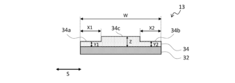
- 4 is a schematic cross-sectional view of the separator taken along line L1-L1 in FIG. 3
- FIG. 3 is a partial schematic cross-sectional view for explaining a state in which the separator of the wound electrode assembly shown in FIG. 2 and the outermost peripheral tape face each other;
- a non-aqueous electrolyte secondary battery will be described below as an example of the secondary battery of the present disclosure.
- the secondary battery of the present disclosure is not limited to the following non-aqueous electrolyte secondary batteries, and can be applied to various secondary batteries without departing from the technical idea of the present disclosure.
- FIG. 1 is a schematic cross-sectional view of a non-aqueous electrolyte secondary battery that is an example of an embodiment.
- the non-aqueous electrolyte secondary battery 10 shown in FIG. It has insulating plates 18 and 19 arranged and a battery case 15 that accommodates the above members.
- the battery case 15 is composed of a bottomed cylindrical case body 16 and a sealing member 17 that closes the opening of the case body 16 .
- Examples of the battery case 15 include a cylindrical or rectangular metal case, a resin case formed by laminating resin sheets (so-called laminate type), and the like.
- the case body 16 is, for example, a bottomed cylindrical metal container.
- a gasket 28 is provided between the case body 16 and the sealing member 17 to ensure hermeticity inside the battery.
- the case main body 16 has an overhanging portion 22 that supports the sealing member 17, for example, a portion of the side surface overhanging inward.
- the protruding portion 22 is preferably annularly formed along the circumferential direction of the case body 16 and supports the sealing member 17 on the upper surface thereof.
- the sealing body 17 has a structure in which a filter 23, a lower valve body 24, an insulating member 25, an upper valve body 26, and a cap 27 are layered in order from the electrode body 14 side.
- Each member constituting the sealing member 17 has, for example, a disk shape or a ring shape, and each member except for the insulating member 25 is electrically connected to each other.
- the lower valve body 24 and the upper valve body 26 are connected to each other at their central portions, and an insulating member 25 is interposed between their peripheral edge portions.
- the lower valve body 24 deforms and breaks so as to push the upper valve body 26 upward toward the cap 27, thereby breaking the lower valve body 24 and the upper valve.
- the current path between bodies 26 is interrupted.
- the upper valve body 26 is broken and the gas is discharged from the opening of the cap 27 .
- the positive electrode lead 20 attached to the positive electrode 11 extends through the through hole of the insulating plate 18 toward the sealing member 17, and the negative electrode lead 21 attached to the negative electrode 12 is insulated. It extends to the bottom side of the case body 16 through the outside of the plate 19 .
- the positive electrode lead 20 is connected to the lower surface of the filter 23, which is the bottom plate of the sealing member 17, by welding or the like, and the cap 27, which is the top plate of the sealing member 17 electrically connected to the filter 23, serves as a positive electrode terminal.
- the negative lead 21 is connected to the inner surface of the bottom of the case body 16 by welding or the like, and the case body 16 serves as a negative terminal.
- FIG. 2 is a schematic perspective view showing an example of a wound electrode body.
- the electrode body 14 is formed by interposing the separator 13 between the positive electrode 11 and the negative electrode 12 and winding these members.
- a winding end portion 14 a of the electrode body 14 is present on the outermost peripheral surface of the electrode body 14 .
- a winding end portion 14a of the electrode body 14 is a winding end portion of the members (positive electrode 11, negative electrode 12, separator 13) of the electrode body 14 on the outermost peripheral surface of the electrode body 14.
- FIG. For example, in order to bring the negative electrode current collector that constitutes the negative electrode 12 into contact with the case body 16, the negative electrode 12 (substantially the negative electrode current collector) is extended by one turn or more from the winding end portion of the positive electrode 11 and the separator 13.
- the outermost peripheral surface of the electrode body 14 is wound and used as the negative electrode 12 . Further, for example, when the winding end portions of the positive electrode 11, the negative electrode 12, and the separator 13 are located at different positions on the outermost peripheral surface of the electrode body 14, the respective winding end portions are located at the winding end portion 14a of the electrode body 14. (That is, there are three winding end portions 14a on the outermost peripheral surface of the electrode body 14).
- a first outermost tape 30a and a second outermost tape 30b are attached to the outermost peripheral surface of the electrode body 14 so as to straddle the winding end portion 14a of the electrode body 14. have.
- the first outermost peripheral tape 30a is arranged on one end side of the electrode body 14 in the winding axial direction (arrow S shown in FIG. 2).
- the first outermost peripheral tape 30a may be arranged with a predetermined gap from one end of the electrode assembly 14 in the winding axial direction, or may be arranged at one end of the electrode assembly 14 in the winding axial direction. They may be arranged close to each other without leaving a gap.
- the second outermost tape 30b is arranged on the other end side of the electrode body 14 in the winding axial direction. As shown in FIG. 2, the second outermost peripheral tape 30b may be arranged with a predetermined gap from the other end of the electrode assembly 14 in the winding axial direction, or may be arranged at one end of the electrode assembly 14 in the winding axial direction. , and may be arranged without leaving a gap.
- the outermost peripheral tapes (30a, 30b) are referred to, both the first outermost peripheral tape 30a and the second outermost peripheral tape 30b are referred to.
- the members constituting the electrode body 14 are fixed. That is, the wound state of the positive electrode 11, the negative electrode 12, and the separator 13 is maintained without unraveling.
- the outermost peripheral tapes (30a, 30b) wrap around the outermost peripheral surface of the electrode assembly 14 one or more times.
- conventionally known tapes used for wound electrode bodies are applied for the outermost peripheral tapes (30a, 30b).
- FIG. 3 is a schematic plan view of the separator before it is wound around the electrode body
- FIG. 4 is a schematic cross-sectional view of the separator taken along line L1-L1 in FIG.
- An arrow S shown in the drawing indicates the winding axial direction of the electrode assembly 14, and an arrow R orthogonal to the arrow S indicates the winding direction of the separator 13 (that is, the winding direction of the members constituting the electrode assembly 14).
- the separator 13 has a base layer 32 and a heat-resistant layer 34 arranged on one side of the base layer 32 .
- the heat-resistant layer 34 is not limited to being arranged on one side of the base layer 32 , and may be arranged on both sides of the base layer 32 .
- the heat-resistant layer 34 is used as the positive electrode from the viewpoint of improving the charge-discharge cycle characteristics and safety of the battery. It is preferable to stack the separator 13 and the positive electrode 11 so as to face the separator 11 .
- the separator 13 may be designed to be larger in width and length than the positive electrode 11 and the negative electrode 12 in order to prevent short-circuiting between the positive and negative electrodes. In this case, when the positive electrode 11 and the negative electrode 12 are stacked on the separator 13 when the electrode body 14 is manufactured, the separator 13 protrudes from the positive electrode 11 and the negative electrode 12 .
- the heat-resistant layer 34 includes a first end heat-resistant layer 34a having a predetermined width from one end of the heat-resistant layer 34 in the width direction along the winding axis direction of the electrode body 14 toward the center, A second end heat-resistant layer 34b having a predetermined width from the other end of the heat-resistant layer 34 in the width direction along the winding axis direction of the electrode body 14 to the center side, a first end heat-resistant layer 34a, and a second end heat-resistant layer 34a. It has a central heat-resistant layer 34c sandwiched between it and the layer 34b.
- FIG. 5 is a partial schematic cross-sectional view for explaining the opposing state of the separator of the wound electrode body shown in FIG. 2 and the outermost peripheral tape.
- the wound-type electrode body 14 is in a state in which the positive electrode 11, the negative electrode 12, and the separator 13 are stacked in a direction perpendicular to the winding axial direction (arrow S) of the electrode body 14.
- FIG. Only one of the laminated separators 13 and the outermost tapes (30a, 30b) adhered to the outermost outer surface of the electrode assembly 14 are shown for illustration.
- At least part of the first outermost peripheral tape 30 a faces the first end heat-resistant layer 34 a of the separator 13
- at least part of the second outermost peripheral tape 30 b faces the second edge of the separator 13 . It faces the edge heat-resistant layer 34b.
- at least part of the outermost tapes (30a, 30b) faces the first end heat-resistant layer 34a or the second end heat-resistant layer 34b means that the first outermost tape 30a is projected onto the separator 13.
- At least part of the projection area overlaps at least part of the first end heat-resistant layer 34a, and at least part of the projection area when the second outermost peripheral tape 30b is projected onto the separator 13 is the second end heat-resistant layer 34b. It means a state that overlaps with at least part of
- the thickness (Y1) of the first end heat-resistant layer 34a and the thickness (Y2) of the second end heat-resistant layer 34b are each equal to the thickness (Z) of the central heat-resistant layer 34c. Thinner and thicker than 0.001 mm. Further, referring to FIG. 5, the length (W) of the separator 13 in the width direction along the winding axis direction (arrow S) of the electrode assembly 14 is extended from one end of the separator 13 in the width direction to the first outermost peripheral tape 30a.
- the ratio (A2/W) of the length (A2) from the other end of the second outermost peripheral tape 30b to the center side end in the width direction is 0.25 or less.
- the members (the positive electrode 11, the negative electrode 12, or the separator 13) forming the outermost peripheral surface of the electrode body 14 are suppressed from breaking at the ends of the outermost peripheral tapes (30a, 30b). . Further, expansion of the negative electrode at the central portion of the electrode body due to uneven reaction of the electrode body 14 is suppressed. And from these things, a short-circuit risk is reduced.
- the thickness (Y1) of the first end heat-resistant layer 34a and the thickness (Y2) of the second end heat-resistant layer 34b are set to 0.001 mm or less, for example, separator shrinkage due to deterioration in heat resistance of the separator 13 may cause an internal short circuit.
- the ratio (Z/Y2) of the thickness (Z) of the heat-resistant layer 34c is preferably 1.4 or more.
- the thickness (Z) of the central heat-resistant layer 34c is preferably 0.0045 mm or more.
- the heat resistance of the separator 13 can be improved more than when it is less than 0.0045 mm. Further, if the expansion of the negative electrode in the central portion of the electrode assembly increases due to uneven electrode reaction, the risk of short circuit may increase. , leading to a reduction in the risk of a short circuit due to expansion of the negative electrode at the center of the electrode body.
- At least part of the first outermost peripheral tape 30a faces the first end heat resistant layer 34a, and at least part of the second outermost peripheral tape 30b faces the second end heat resistant layer 34b.
- the entire first outermost peripheral tape 30a faces the first end heat-resistant layer 34a, and the entire second outermost peripheral tape 30b faces the second end heat-resistant layer 34b.
- the entirety of the outermost peripheral tapes (30a, 30b) facing the first end heat-resistant layer 34a or the second end heat-resistant layer 34b means that the projection area of the first outermost peripheral tape 30a projected onto the separator 13 is A state in which the entire area overlaps at least a portion of the first end heat-resistant layer 34a, and a state in which the entire projection area when the second outermost peripheral tape 30b is projected onto the separator 13 overlaps at least a portion of the second end heat-resistant layer 34b.
- the ratio (X2/W) of the predetermined width (X2) of the second end heat-resistant layer 34b to the length (W) in the width direction is preferably 0.25 or less, and 0.10 or more. It is more preferably 0.25 or less.
- the heat resistance of the separator 13 may be improved, for example, compared to when it exceeds 0.25.
- the base material layer 32 is composed of, for example, a porous base material, specifically a microporous thin film, a woven fabric, a nonwoven fabric, or the like.
- the material of the base material layer 32 is not particularly limited, but examples thereof include polyolefins such as polyethylene, polypropylene, copolymers of polyethylene and ⁇ -olefin, acrylic resins, polystyrene, polyesters, and cellulose.
- the base material layer 32 may have a single layer structure or a laminated structure. Although the thickness of the base layer 32 is not particularly limited, it is preferably in the range of 3 ⁇ m to 20 ⁇ m, for example.
- the average pore size of the base material layer 32 is, for example, preferably in the range of 0.02 ⁇ m to 0.5 ⁇ m, more preferably in the range of 0.03 ⁇ m to 0.3 ⁇ m.
- the average pore diameter of the base material layer 32 is measured using a perm porometer (manufactured by Seika Sangyo Co., Ltd.) capable of measuring pore diameters by the bubble point method (JIS K3832, ASTM F316-86).
- the heat-resistant layer 34 contains, for example, filler and resin. By including the filler in the heat-resistant layer 34, for example, the heat-resistant layer 34 can be given an effect of suppressing thermal shrinkage.
- the melting point or thermal softening point of the filler is, for example, preferably 150° C. or higher, more preferably 200° C. or higher.
- fillers include metal oxide particles, metal nitride particles, metal fluoride particles and metal carbide particles.
- metal oxide particles include aluminum oxide, titanium oxide, magnesium oxide, zirconium oxide, nickel oxide, silicon oxide, and manganese oxide.
- metal nitride particles include titanium nitride, boron nitride, aluminum nitride, magnesium nitride, and silicon nitride.
- metal fluoride particles include aluminum fluoride, lithium fluoride, sodium fluoride, magnesium fluoride, calcium fluoride, barium fluoride, and the like.
- metal carbide particles include silicon carbide, boron carbide, titanium carbide, and tungsten carbide.
- the fillers include porous aluminosilicates such as zeolite (M2 /nO.Al2O3.xSiO2.yH2O , M is a metal element, x ⁇ 2 , y ⁇ 0 ) , talc ( Mg3 Layered silicates such as Si 4 O 10 (OH) 2 ), minerals such as barium titanate (BaTiO 3 ), strontium titanate (SrTiO 3 ), and the like may also be used. In addition, these may be used individually by 1 type, and may use 2 or more types together.
- the BET specific surface area of the filler is not particularly limited, but is preferably in the range of 1 m 2 /g to 20 m 2 /g, more preferably in the range of 3 m 2 /g to 15 m 2 /g.
- the average particle size of the filler is not particularly limited, it is preferably in the range of 0.1 ⁇ m to 5 ⁇ m, more preferably in the range of 0.2 ⁇ m to 1 ⁇ m.
- the content of the filler is, for example, preferably in the range of 70% by mass or more and 95% by mass or less with respect to the total mass of the heat-resistant layer 34.
- the resin preferably has a function as a binder that bonds the fillers together and the fillers and the base material layer.
- the resin include fluorine-based resins such as polyvinylidene fluoride (PVDF) and polytetrafluoroethylene (PTFE), polyimide-based resins, acrylic resins, and polyolefin-based resins. These may be used alone or in combination of two or more.
- the content of the resin is preferably, for example, in the range of 5% by mass to 15% by mass with respect to the total mass of the heat-resistant layer 34.
- a heat-resistant layer slurry containing a filler and a resin is prepared. After applying the slurry to the entire surface of the substrate layer 32 , the slurry is dried to form the heat-resistant layer 34 on the entire surface of the substrate layer 32 . Further, the above slurry is applied to the central portion of the heat-resistant layer 34 in the width direction along the longitudinal direction of the heat-resistant layer 34, and then dried.
- a central heat-resistant layer 34c having a thickness at the central portion in the width direction of the heat-resistant layer 34, and a first end heat-resistant layer 34a and a second end heat-resistant layer having thin thickness at both ends of the heat-resistant layer 34 in the width direction are formed.
- a separator 13 having 34b formed on the substrate layer 32 is obtained.
- the positive electrode 11 has, for example, a positive electrode current collector and a positive electrode active material layer provided on the positive electrode current collector.
- a positive electrode current collector for example, a foil of a metal such as aluminum that is stable in the potential range of the positive electrode, a film in which the metal is arranged on the surface layer, or the like can be used.
- the positive electrode active material layer contains a positive electrode active material, and also contains a conductive material and a binder.
- Examples of the positive electrode active material include lithium transition metal composite oxides, and specific examples include lithium cobalt oxide, lithium manganate, lithium nickel oxide, lithium nickel manganese composite oxide, lithium nickel cobalt composite oxide, and the like. Al, Ti, Zr, Nb, B, W, Mg, Mo, etc. may be added to these lithium transition metal composite oxides.
- carbon powder such as carbon black, acetylene black, ketjen black, and graphite may be used singly or in combination of two or more.
- binders include fluorine-based resins such as polytetrafluoroethylene (PTFE) and polyvinylidene fluoride (PVdF), polyacrylonitrile (PAN), polyimide-based resins, acrylic-based resins, and polyolefin-based resins. These may be used alone or in combination of two or more.
- fluorine-based resins such as polytetrafluoroethylene (PTFE) and polyvinylidene fluoride (PVdF), polyacrylonitrile (PAN), polyimide-based resins, acrylic-based resins, and polyolefin-based resins. These may be used alone or in combination of two or more.
- the negative electrode 12 has, for example, a negative electrode current collector and a negative electrode active material layer provided on the negative electrode current collector.
- a negative electrode current collector for example, a foil of a metal such as copper that is stable in the potential range of the negative electrode, a film having the metal on the surface layer, or the like can be used.
- the negative electrode active material layer contains a negative electrode active material and also contains a binder and the like.
- a carbon material capable of intercalating and deintercalating lithium ions can be used, and in addition to graphite, non-graphitizable carbon, graphitizable carbon, fibrous carbon, coke, carbon black, etc. can be used. can be done. Furthermore, as non-carbon materials, silicon, tin, and alloys and oxides based on these can be used.
- binders include fluorine-based resins, PAN, polyimide-based resins, acrylic resins, polyolefin-based resins, styrene-butadiene rubber (SBR), nitrile-butadiene rubber (NBR), carboxymethylcellulose (CMC) or salts thereof, poly Acrylic acid (PAA) or its salt, polyvinyl alcohol (PVA), etc. are mentioned. These may be used alone or in combination of two or more.
- a non-aqueous electrolyte includes a non-aqueous solvent and an electrolyte salt dissolved in the non-aqueous solvent.
- non-aqueous solvents examples include esters, ethers, nitriles such as acetonitrile, amides such as dimethylformamide, and mixed solvents of two or more thereof.
- the non-aqueous solvent may contain a halogen-substituted product obtained by substituting at least part of the hydrogen atoms of these solvents with halogen atoms such as fluorine.
- esters examples include cyclic carbonates such as ethylene carbonate (EC), propylene carbonate (PC) and butylene carbonate, dimethyl carbonate (DMC), ethyl methyl carbonate (EMC), diethyl carbonate (DEC), methyl propyl carbonate. , Ethyl propyl carbonate, methyl isopropyl carbonate and other chain carbonates, ⁇ -butyrolactone, ⁇ -valerolactone and other cyclic carboxylic acid esters, methyl acetate, ethyl acetate, propyl acetate, methyl propionate (MP), ethyl propionate, etc. and chain carboxylic acid esters of.
- cyclic carbonates such as ethylene carbonate (EC), propylene carbonate (PC) and butylene carbonate, dimethyl carbonate (DMC), ethyl methyl carbonate (EMC), diethyl carbonate (DEC), methyl propyl carbonate.
- ethers examples include 1,3-dioxolane, 4-methyl-1,3-dioxolane, tetrahydrofuran, 2-methyltetrahydrofuran, propylene oxide, 1,2-butylene oxide, 1,3-dioxane, 1,4 -dioxane, 1,3,5-trioxane, furan, 2-methylfuran, 1,8-cineol, cyclic ethers such as crown ether, 1,2-dimethoxyethane, diethyl ether, dipropyl ether, diisopropyl ether, dibutyl ether , dihexyl ether, ethyl vinyl ether, butyl vinyl ether, methyl phenyl ether, ethyl phenyl ether, butyl phenyl ether, pentyl phenyl ether, methoxytoluene, benzyl ethyl ether, diphenyl ether, cycl
- a fluorinated cyclic carbonate such as fluoroethylene carbonate (FEC), a fluorinated chain carbonate, a fluorinated chain carboxylate such as methyl fluoropropionate (FMP), and the like.
- FEC fluoroethylene carbonate
- FMP fluorinated chain carboxylate
- FEC fluoroethylene carbonate
- FMP fluorinated chain carboxylate
- the electrolyte salt is a lithium salt.
- lithium salts include LiBF4 , LiClO4 , LiPF6 , LiAsF6 , LiSbF6 , LiAlCl4 , LiSCN, LiCF3SO3 , LiCF3CO2 , Li(P( C2O4 ) F4 ) , LiPF 6-x (C n F 2n+1 ) x (1 ⁇ x ⁇ 6, n is 1 or 2), LiB 10 Cl 10 , LiCl, LiBr, LiI, lithium chloroborane, lithium lower aliphatic carboxylate, Li 2 B 4O7 , borates such as Li (B( C2O4 ) F2 ), LiN( SO2CF3 ) 2 , LiN( C1F2l + 1SO2 )( CmF2m + 1SO2 ) ⁇ l , where m is an integer of 1 or more ⁇ .
- Lithium salts may be used singly or in combination. Of these, it is preferable to use LiPF 6 from the viewpoint of ion conductivity, electrochemical stability, and the like.
- the lithium salt concentration is preferably 0.8 to 1.8 mol per 1 L of solvent.
- ⁇ Example 1> 100 parts by mass of a positive electrode active material represented by LiNi 0.91 Co 0.04 Al 0.05 O 2 , 1.0 parts by mass of acetylene black as a conductive material, and 0.9 parts by mass of polyvinylidene fluoride as a binder Parts by mass were mixed in a solvent of N-methyl-2-pyrrolidone to prepare a positive electrode mixture slurry.
- the positive electrode mixture slurry was applied to both sides of an aluminum foil having a thickness of 20 ⁇ m, dried, and then rolled by a roll press. After that, it was cut to a predetermined size. Thus, a positive electrode was obtained in which positive electrode active material layers were formed on both surfaces of the positive electrode current collector.
- a negative electrode 80 parts by mass of graphite powder, 20 parts by mass of Si oxide, 1 part by mass of carboxymethyl cellulose (CMC), and 1 part by mass of styrene-butadiene rubber are mixed, and the mixture is dispersed in water to prepare a negative electrode mixture slurry. prepared.
- the negative electrode mixture slurry was applied to both sides of a copper foil having a thickness of 10 ⁇ m, dried, and then rolled by a roll press. The obtained member was cut into a predetermined size. Thus, a negative electrode having negative electrode active material layers formed on both sides of the negative electrode current collector was obtained.
- the sheet of the polyolefin resin composition was washed with water, dried, and stretched by a tenter stretching machine to obtain a porous polyolefin resin composition sheet. This was used as a substrate layer.
- the thickness of the base material layer was 0.014 mm.
- a predetermined amount of heat-resistant layer slurry was applied to the entire surface of the substrate layer, and the aramid resin was precipitated in an atmosphere of 60°C temperature and 70% humidity. After that, the precipitated aramid resin was washed with water and dried. As a result, a heat-resistant layer containing aramid resin and alumina was formed on the entire surface of the substrate layer.
- the heat-resistant layer slurry was applied onto the heat-resistant layer in a predetermined width along the longitudinal direction of the heat-resistant layer at the central portion in the width direction of the heat-resistant layer. After that, the aramid resin was precipitated, washed with water, and dried in the same manner as described above. The obtained member was slit at a width of 62 mm.
- the end heat-resistant layers (the first end heat-resistant layer and the second end heat-resistant layer) formed at both ends in the width direction of the heat-resistant layer, the first end heat-resistant layer and the second end heat-resistant layer A separator was obtained in which a central heat-resistant layer sandwiched between the layers was formed on the base material layer.
- Example 1 the thickness (Y1) of the first end heat-resistant layer and the thickness (Y2) of the second end heat-resistant layer were each set to 0.0030 mm. Further, in Example 1, the thickness (Z) of the central heat-resistant layer was set to 0.0050 mm. In each example and each comparative example, (Y1) and (Y2) are designed to be the same. (Y).
- the ratio (X1/W) of the width length (X1) of the first end heat-resistant layer to the width length (W) of the separator and the second end heat-resistant layer to the width length (W) of the separator The ratio (X2/W) of the width to the length (X2) of each was set to 0.19.
- (X1/W) and (X2/W) are designed to be the same in both Examples and Comparative Examples, (X1/W) and (X2/W) ) is described as the ratio (X/W) of the width (X) of the edge heat-resistant layer to the width (W) of the separator.
- a positive electrode lead was attached to the positive electrode current collector, and a negative electrode lead was attached to the negative electrode current collector. Then, the separator was arranged between the positive electrode and the negative electrode so that the heat-resistant layer of the separator faced the positive electrode. After that, these were wound to produce a wound electrode body having the outermost peripheral surface of the electrode body as a negative electrode current collector. Then, a first outermost tape and a second outermost tape having a width of 9 mm were wrapped around one end side and the other end side of the outermost circumferential surface of the electrode body in the winding axial direction and attached to the electrode body.
- Example 1 the ratio (A1/W) of the length (A1) from one end in the width direction of the separator to the central end in the width direction of the first outermost peripheral tape with respect to the length (W) of the width of the separator was set to 0.19, and the entire first outermost peripheral tape was opposed to the first end heat-resistant layer.
- the ratio (A2/W) of the length (A2) from the other end of the separator in the width direction to the central end of the second outermost peripheral tape in the width direction with respect to the length (W) of the width of the separator is set to 0. .19, and the entire second outermost peripheral tape was opposed to the second end heat-resistant layer.
- (A1/W) and (A2/W) are designed to be the same in each example and each comparative example, (A1/W) and (A2/W) ) is described as the ratio (A/W) of the length (A) from the widthwise end of the separator to the widthwise central end of the outermost peripheral tape with respect to the widthwise length (W) of the separator.
- Example 2 a separator was produced in the same manner as in Example 1, except that the thickness (Y) of the edge heat-resistant layer was 0.0033 mm and the thickness (Z) of the central heat-resistant layer was 0.0047 mm. A water electrolyte secondary battery was produced.
- Example 3 the ratio (X/W) of the width length (X) of the edge heat-resistant layer to the width length (W) of the separator was set to 0.15, and part of the outermost peripheral tape was A non-aqueous electrolyte secondary battery was produced in the same manner as in Example 1, except that the separator was made to face the heat-resistant layer.
- Example 4 In Example 3, except that the ratio (X/W) of the width (X) of the edge heat-resistant layer to the width (W) of the separator was 0.29, A non-aqueous electrolyte secondary battery was produced in the same manner as in Example 1.
- Comparative Example 1 a predetermined amount of heat-resistant layer slurry was applied to the entire surface of the substrate layer in one step, and the thickness (Y) of the end heat-resistant layer was set to 0.0040 mm, and the thickness of the center heat-resistant layer was set to 0.0040 mm.
- a non-aqueous electrolyte secondary battery was produced in the same manner as in Example 1, except that the separator was produced with (Z) set to 0.0040 mm.
- Comparative Example 2 a predetermined amount of heat-resistant layer slurry was applied to the entire surface of the substrate layer in one step, and the thickness (Y) of the end heat-resistant layer was set to 0.0050 mm, and the thickness of the center heat-resistant layer was set to 0.0050 mm.
- a non-aqueous electrolyte secondary battery was produced in the same manner as in Example 1, except that the separator was produced with (Z) set to 0.0050 mm.
- Comparative Example 3 a predetermined amount of heat-resistant layer slurry was applied to the entire surface of the substrate layer in one step, and the thickness (Y) of the edge heat-resistant layer was set to 0.0030 mm, and the thickness of the center heat-resistant layer was set to 0.0030 mm.
- a non-aqueous electrolyte secondary battery was produced in the same manner as in Example 1, except that the separator was produced with (Z) set to 0.0030 mm.
- Comparative Example 4 a non-aqueous electrolyte secondary battery was produced in the same manner as in Example 1, except that a separator was produced in which the thickness (Y) of the edge heat-resistant layer was 0.0010 mm.
- Comparative Example 5 In Comparative Example 5, the positions of the first outermost peripheral tape and the second outermost peripheral tape were set to the central side in the winding axial direction of the electrode body, and from the end in the width direction of the separator with respect to the width (W) of the separator, A separator was produced in which the ratio (A/W) of the distance (A) to the central edge in the width direction of the outermost peripheral tape was set to 0.29. A non-aqueous electrolyte secondary battery was produced in the same manner as in Example 1, except that such a separator was used.
- the ratio (A/W) of the distance (A) from the widthwise end of the separator to the widthwise center side end of the outermost peripheral tape to the widthwise length (W) of the separator is 0.25 or less.
Landscapes
- Chemical & Material Sciences (AREA)
- Chemical Kinetics & Catalysis (AREA)
- Electrochemistry (AREA)
- General Chemical & Material Sciences (AREA)
- Engineering & Computer Science (AREA)
- Manufacturing & Machinery (AREA)
- Inorganic Chemistry (AREA)
- Secondary Cells (AREA)
- Cell Separators (AREA)
Abstract
Provided is a secondary battery in which: at least a portion of a first outermost peripheral tape (30a) opposes a first end portion heat resistant layer (34a); at least a portion of a second outermost peripheral tape (30b) opposes a second end portion heat resistant layer (34b); a thickness of the first end portion heat resistant layer (34a) and a thickness of the second end portion heat resistant layer (34b) are less than a thickness of a central portion heat resistant layer (34c) and are greater than 0.001 mm; and a ratio (A1/W) of a length (A1) from one end, in a width direction, of a separator (13) to a central side end portion, in the width direction, of the first outermost peripheral tape (30a) to a length (W), in the width direction, of the separator (13), and a ratio (A2/W) of a length (A2) from the other end, in the width direction, of the separator (13) to a central side end portion, in the width direction, of the second outermost peripheral tape (30b) to the length (W), in the width direction, of the separator (13), are each at most equal to 0.25.
Description
本開示は、二次電池に関する。
The present disclosure relates to secondary batteries.
近年、高出力、高エネルギー密度の二次電池として、正極と負極とがセパレータを介して巻回された巻回型の電極体を備える非水電解質二次電池が広く利用されている。
In recent years, as a secondary battery with high output and high energy density, a non-aqueous electrolyte secondary battery having a wound electrode assembly in which a positive electrode and a negative electrode are wound with a separator interposed has been widely used.
例えば、特許文献1及び2には、耐熱層を有するセパレータを使用した非水電解質二次電池について開示されている。
For example, Patent Literatures 1 and 2 disclose a non-aqueous electrolyte secondary battery using a separator having a heat-resistant layer.
ところで、巻回型の電極体を使用した二次電池では、例えば、電極体を構成する部材を固定するために、電極体の最外周面にテープを巻き付けている。しかし、二次電池の充放電を繰り返すと、テープの端部(エッジ)にて、電極体の最外周面をなす部材(負極、正極、又はセパレータ)が切れる場合がある。そして、電極体の最外周面において切れた部材は短絡リスクとなる。また、電極体の最外周面をなす部材が切れなくても、例えば、電極体の反応ムラによる電極体中心部での負極膨張により、短絡リスクが大きくなる場合がある。
By the way, in a secondary battery using a wound electrode body, for example, a tape is wound around the outermost peripheral surface of the electrode body in order to fix the members constituting the electrode body. However, when the secondary battery is repeatedly charged and discharged, the member (negative electrode, positive electrode, or separator) forming the outermost peripheral surface of the electrode body may be cut at the edge of the tape. A cut member on the outermost peripheral surface of the electrode assembly poses a risk of short circuit. Even if the member forming the outermost peripheral surface of the electrode body is not cut, for example, the risk of short circuit may increase due to expansion of the negative electrode at the center of the electrode body due to uneven reaction of the electrode body.
そこで、本開示の目的は、充放電の繰り返しによる電極体最外周面の部材切れを抑制すること、更には短絡リスクを低減することを可能とする二次電池を提供することである。
Therefore, an object of the present disclosure is to provide a secondary battery that can suppress member breakage on the outermost peripheral surface of the electrode body due to repeated charging and discharging and further reduce the risk of short circuit.
本開示の一態様に係る二次電池は、正極と負極がセパレータを介して巻回された巻回型の電極体と、前記電極体の最外周面に、前記電極体の巻回終端部を跨ぐように貼着された最外周テープとを備える非水電解質二次電池であって、前記セパレータは、基材層と、前記基材層の少なくとも一方の面に配置される耐熱層とを有し、前記耐熱層は、前記電極体の巻回軸方向に沿うセパレータの幅方向の一端から中央側に所定の幅を有する第1端部耐熱層と、前記電極体の巻回軸方向に沿うセパレータの幅方向の他端から中央側に所定の幅を有する第2端部耐熱層と、前記第1耐熱層と前記第2耐熱層との間に挟まれる中央部耐熱層とを有し、前記最外周テープは、前記電極体の巻回軸方向の一端側に配置された第1最外周テープ及び前記電極体の巻回軸方向の他端側に配置された第2最外周テープを有し、前記第1最外周テープの少なくとも一部は、前記第1端部耐熱層と対向し、前記第2最外周テープの少なくとも一部は、前記第2端部耐熱層と対向し、前記第1端部耐熱層の厚さ(Y1)及び前記第2端部耐熱層の厚さ(Y2)は、前記中央部耐熱層の厚さ(Z)より薄く、且つ0.001mmより厚く、前記セパレータの幅方向の長さ(W)に対する前記セパレータの幅方向の一端から前記第1最外周テープの幅方向の中央側端部までの長さ(A1)の比(A1/W)、及び前記セパレータの幅方向の長さ(W)に対する前記セパレータの幅方向の他端から前記第2最外周テープの幅方向の中央側端部までの長さ(A2)の比(A2/W)はそれぞれ、0.25以下であることを特徴とする。
A secondary battery according to an aspect of the present disclosure includes a wound electrode body in which a positive electrode and a negative electrode are wound with a separator interposed therebetween; A non-aqueous electrolyte secondary battery comprising an outermost peripheral tape attached so as to straddle the separator, wherein the separator has a base material layer and a heat-resistant layer disposed on at least one surface of the base material layer. The heat-resistant layer includes a first end heat-resistant layer having a predetermined width from one end in the width direction of the separator along the winding axis direction of the electrode body to the center side, and a heat-resistant layer extending along the winding axis direction of the electrode body. A second end heat-resistant layer having a predetermined width on the center side from the other end in the width direction of the separator, and a central heat-resistant layer sandwiched between the first heat-resistant layer and the second heat-resistant layer, The outermost tape has a first outermost tape arranged on one end side in the winding axial direction of the electrode assembly and a second outermost circumference tape arranged on the other end side in the winding axial direction of the electrode assembly. At least part of the first outermost peripheral tape faces the first end heat resistant layer, at least part of the second outermost peripheral tape faces the second end heat resistant layer, The thickness (Y1) of one end heat-resistant layer and the thickness (Y2) of the second end heat-resistant layer are thinner than the thickness (Z) of the central heat-resistant layer and thicker than 0.001 mm, and the separator The ratio (A1/W) of the length (A1) from one end in the width direction of the separator to the center side end in the width direction of the first outermost peripheral tape with respect to the length (W) in the width direction of the separator, and the separator The ratio (A2/W) of the length (A2) from the other end in the width direction of the separator to the center side end in the width direction of the second outermost peripheral tape with respect to the length (W) in the width direction of It is characterized by being 0.25 or less.
本開示によれば、充放電の繰り返しによる電極体最外周面の部材切れを抑制し、更には短絡リスクを低減することが可能となる。
According to the present disclosure, it is possible to suppress breakage of members on the outermost peripheral surface of the electrode body due to repeated charging and discharging, and further reduce the risk of short circuits.
以下に、本開示の二次電池の一例として、非水電解質二次電池を例に説明する。しかし、本開示の二次電池は以下の非水電解質二次電池に特定されるものではなく、本開示の技術思想を逸脱しない範囲において種々の二次電池に適用される。
A non-aqueous electrolyte secondary battery will be described below as an example of the secondary battery of the present disclosure. However, the secondary battery of the present disclosure is not limited to the following non-aqueous electrolyte secondary batteries, and can be applied to various secondary batteries without departing from the technical idea of the present disclosure.
図1は、実施形態の一例である非水電解質二次電池の模式断面図である。図1に示す非水電解質二次電池10は、正極11及び負極12がセパレータ13を介して巻回されてなる巻回型の電極体14と、非水電解質と、電極体14の上下にそれぞれ配置された絶縁板18,19と、上記部材を収容する電池ケース15と、を備える。電池ケース15は、有底円筒形状のケース本体16と、ケース本体16の開口部を塞ぐ封口体17とにより構成されている。電池ケース15としては、円筒形、角形等の金属製ケース、樹脂シートをラミネートして形成された樹脂製ケース(所謂ラミネート型)などが例示できる。
FIG. 1 is a schematic cross-sectional view of a non-aqueous electrolyte secondary battery that is an example of an embodiment. The non-aqueous electrolyte secondary battery 10 shown in FIG. It has insulating plates 18 and 19 arranged and a battery case 15 that accommodates the above members. The battery case 15 is composed of a bottomed cylindrical case body 16 and a sealing member 17 that closes the opening of the case body 16 . Examples of the battery case 15 include a cylindrical or rectangular metal case, a resin case formed by laminating resin sheets (so-called laminate type), and the like.
ケース本体16は、例えば有底円筒形状の金属製容器である。ケース本体16と封口体17との間にはガスケット28が設けられ、電池内部の密閉性が確保される。ケース本体16は、例えば側面部の一部が内側に張出した、封口体17を支持する張り出し部22を有する。張り出し部22は、ケース本体16の周方向に沿って環状に形成されることが好ましく、その上面で封口体17を支持する。
The case body 16 is, for example, a bottomed cylindrical metal container. A gasket 28 is provided between the case body 16 and the sealing member 17 to ensure hermeticity inside the battery. The case main body 16 has an overhanging portion 22 that supports the sealing member 17, for example, a portion of the side surface overhanging inward. The protruding portion 22 is preferably annularly formed along the circumferential direction of the case body 16 and supports the sealing member 17 on the upper surface thereof.
封口体17は、電極体14側から順に、フィルタ23、下弁体24、絶縁部材25、上弁体26、及びキャップ27が積層された構造を有する。封口体17を構成する各部材は、例えば円板形状又はリング形状を有し、絶縁部材25を除く各部材は互いに電気的に接続されている。下弁体24と上弁体26は各々の中央部で互いに接続され、各々の周縁部の間には絶縁部材25が介在している。内部短絡等による発熱で非水電解質二次電池10の内圧が上昇すると、例えば下弁体24が上弁体26をキャップ27側に押し上げるように変形して破断し、下弁体24と上弁体26の間の電流経路が遮断される。さらに内圧が上昇すると、上弁体26が破断し、キャップ27の開口部からガスが排出される。
The sealing body 17 has a structure in which a filter 23, a lower valve body 24, an insulating member 25, an upper valve body 26, and a cap 27 are layered in order from the electrode body 14 side. Each member constituting the sealing member 17 has, for example, a disk shape or a ring shape, and each member except for the insulating member 25 is electrically connected to each other. The lower valve body 24 and the upper valve body 26 are connected to each other at their central portions, and an insulating member 25 is interposed between their peripheral edge portions. When the internal pressure of the non-aqueous electrolyte secondary battery 10 rises due to heat generation due to an internal short circuit or the like, for example, the lower valve body 24 deforms and breaks so as to push the upper valve body 26 upward toward the cap 27, thereby breaking the lower valve body 24 and the upper valve. The current path between bodies 26 is interrupted. When the internal pressure further increases, the upper valve body 26 is broken and the gas is discharged from the opening of the cap 27 .
図1に示す非水電解質二次電池10では、正極11に取り付けられた正極リード20が絶縁板18の貫通孔を通って封口体17側に延び、負極12に取り付けられた負極リード21が絶縁板19の外側を通ってケース本体16の底部側に延びている。正極リード20は封口体17の底板であるフィルタ23の下面に溶接等で接続され、フィルタ23と電気的に接続された封口体17の天板であるキャップ27が正極端子となる。負極リード21はケース本体16の底部内面に溶接等で接続され、ケース本体16が負極端子となる。
In the non-aqueous electrolyte secondary battery 10 shown in FIG. 1, the positive electrode lead 20 attached to the positive electrode 11 extends through the through hole of the insulating plate 18 toward the sealing member 17, and the negative electrode lead 21 attached to the negative electrode 12 is insulated. It extends to the bottom side of the case body 16 through the outside of the plate 19 . The positive electrode lead 20 is connected to the lower surface of the filter 23, which is the bottom plate of the sealing member 17, by welding or the like, and the cap 27, which is the top plate of the sealing member 17 electrically connected to the filter 23, serves as a positive electrode terminal. The negative lead 21 is connected to the inner surface of the bottom of the case body 16 by welding or the like, and the case body 16 serves as a negative terminal.
図2は、巻回型の電極体の一例を示す模式斜視図である。電極体14は、正極11と負極12との間にセパレータ13を介在させて、これら部材を巻回することにより形成される。電極体14の最外周面には、電極体14の巻回終端部14aが存在する。電極体14の巻回終端部14aは、電極体14の最外周面における電極体14の部材(正極11、負極12、セパレータ13)の巻き終わり端部である。例えば、負極12を構成する負極集電体をケース本体16に接触させるために、負極12(実質的には負極集電体)を、正極11及びセパレータ13の巻き終わり端部から1周以上長く巻回して、電極体14の最外周面を負極12にする場合があるが、その場合、負極12の巻き終わり端部が電極体14の巻回終端部14aとなる。また、例えば、正極11、負極12、セパレータ13それぞれの巻き終わり端部が、電極体14の最外周面の異なる位置にある場合、それぞれの巻き終わり端部が電極体14の巻回終端部14aとなる(すなわち、電極体14の最外周面には、巻回終端部14aが3つ存在する)。
FIG. 2 is a schematic perspective view showing an example of a wound electrode body. The electrode body 14 is formed by interposing the separator 13 between the positive electrode 11 and the negative electrode 12 and winding these members. A winding end portion 14 a of the electrode body 14 is present on the outermost peripheral surface of the electrode body 14 . A winding end portion 14a of the electrode body 14 is a winding end portion of the members (positive electrode 11, negative electrode 12, separator 13) of the electrode body 14 on the outermost peripheral surface of the electrode body 14. FIG. For example, in order to bring the negative electrode current collector that constitutes the negative electrode 12 into contact with the case body 16, the negative electrode 12 (substantially the negative electrode current collector) is extended by one turn or more from the winding end portion of the positive electrode 11 and the separator 13. In some cases, the outermost peripheral surface of the electrode body 14 is wound and used as the negative electrode 12 . Further, for example, when the winding end portions of the positive electrode 11, the negative electrode 12, and the separator 13 are located at different positions on the outermost peripheral surface of the electrode body 14, the respective winding end portions are located at the winding end portion 14a of the electrode body 14. (That is, there are three winding end portions 14a on the outermost peripheral surface of the electrode body 14).
非水電解質二次電池10は、電極体14の最外周面に、電極体14の巻回終端部14aを跨ぐように貼着されている第1最外周テープ30a及び第2最外周テープ30bを有する。第1最外周テープ30aは、電極体14の巻回軸方向(図2に示す矢印S)の一端側に配置されている。第1最外周テープ30aは、図2に示すように、電極体14の巻回軸方向の一端から所定の隙間を空けて配置されてもよいし、電極体14の巻回軸方向の一端に寄せて、隙間を空けずに配置されてもよい。第2最外周テープ30bは、電極体14の巻回軸方向の他端側に配置されている。第2最外周テープ30bは、図2に示すように、電極体14の巻回軸方向の他端から所定の隙間を空けて配置されてもよいし、電極体14の巻回軸方向の一端に寄せて、隙間を空けずに配置されてもよい。以下、最外周テープ(30a,30b)と称する場合、第1最外周テープ30a及び第2最外周テープ30bの両方を指している。
In the non-aqueous electrolyte secondary battery 10, a first outermost tape 30a and a second outermost tape 30b are attached to the outermost peripheral surface of the electrode body 14 so as to straddle the winding end portion 14a of the electrode body 14. have. The first outermost peripheral tape 30a is arranged on one end side of the electrode body 14 in the winding axial direction (arrow S shown in FIG. 2). As shown in FIG. 2, the first outermost peripheral tape 30a may be arranged with a predetermined gap from one end of the electrode assembly 14 in the winding axial direction, or may be arranged at one end of the electrode assembly 14 in the winding axial direction. They may be arranged close to each other without leaving a gap. The second outermost tape 30b is arranged on the other end side of the electrode body 14 in the winding axial direction. As shown in FIG. 2, the second outermost peripheral tape 30b may be arranged with a predetermined gap from the other end of the electrode assembly 14 in the winding axial direction, or may be arranged at one end of the electrode assembly 14 in the winding axial direction. , and may be arranged without leaving a gap. Hereinafter, when the outermost peripheral tapes (30a, 30b) are referred to, both the first outermost peripheral tape 30a and the second outermost peripheral tape 30b are referred to.
最外周テープ(30a,30b)を電極体14の巻回終端部14aを跨ぐように貼着することにより、電極体14を構成する部材が固定される。すなわち、巻回された正極11、負極12、セパレータ13がほどけずに、巻回された状態が保たれる。電極体14を構成する部材をより強く固定するために、最外周テープ(30a,30b)は電極体14の最外周面を1周以上周回していることが望ましい。最外周テープ(30a,30b)は、例えば、巻回型の電極体に使用される従来公知のテープが適用される。
By attaching the outermost peripheral tapes (30a, 30b) so as to straddle the winding end portion 14a of the electrode body 14, the members constituting the electrode body 14 are fixed. That is, the wound state of the positive electrode 11, the negative electrode 12, and the separator 13 is maintained without unraveling. In order to fix the members constituting the electrode assembly 14 more strongly, it is desirable that the outermost peripheral tapes (30a, 30b) wrap around the outermost peripheral surface of the electrode assembly 14 one or more times. For the outermost peripheral tapes (30a, 30b), for example, conventionally known tapes used for wound electrode bodies are applied.
図3は、電極体に巻回される前の状態のセパレータの模式平面図であり、図4は、図3の線L1-L1に沿ったセパレータの模式断面図である。図に示す矢印Sは電極体14の巻回軸方向を示し、矢印Sに直交する矢印Rは、セパレータ13の巻回方向(すなわち、電極体14を構成する部材の巻回方向)を示している。
3 is a schematic plan view of the separator before it is wound around the electrode body, and FIG. 4 is a schematic cross-sectional view of the separator taken along line L1-L1 in FIG. An arrow S shown in the drawing indicates the winding axial direction of the electrode assembly 14, and an arrow R orthogonal to the arrow S indicates the winding direction of the separator 13 (that is, the winding direction of the members constituting the electrode assembly 14). there is
図4に示すように、セパレータ13は、基材層32と、基材層32の一方の面に配置される耐熱層34を有する。耐熱層34は、基材層32の片面に配置される場合に限定されず、基材層32の両面に配置されていてもよい。基材層32の一方の面に耐熱層34が配置されたセパレータを用いて電極体14を作製する場合には、電池の充放電サイクル特性や安全性向上等の点で、耐熱層34が正極11と向き合うように、セパレータ13と正極11とを重ねることが好ましい。なお、セパレータ13は、正負極間ショートを防止するため、正極11や負極12より幅・長さともに大きく設計されてもよい。この場合、電極体14を作製する際に、正極11及び負極12とセパレータ13とを重ねると、正極11や負極12からセパレータ13がはみ出る形態になる。
As shown in FIG. 4 , the separator 13 has a base layer 32 and a heat-resistant layer 34 arranged on one side of the base layer 32 . The heat-resistant layer 34 is not limited to being arranged on one side of the base layer 32 , and may be arranged on both sides of the base layer 32 . When the electrode body 14 is produced using a separator in which the heat-resistant layer 34 is arranged on one side of the base material layer 32, the heat-resistant layer 34 is used as the positive electrode from the viewpoint of improving the charge-discharge cycle characteristics and safety of the battery. It is preferable to stack the separator 13 and the positive electrode 11 so as to face the separator 11 . The separator 13 may be designed to be larger in width and length than the positive electrode 11 and the negative electrode 12 in order to prevent short-circuiting between the positive and negative electrodes. In this case, when the positive electrode 11 and the negative electrode 12 are stacked on the separator 13 when the electrode body 14 is manufactured, the separator 13 protrudes from the positive electrode 11 and the negative electrode 12 .
図3及び4に示すように、耐熱層34は、電極体14の巻回軸方向に沿う耐熱層34の幅方向の一端から中央側に所定の幅を有する第1端部耐熱層34aと、電極体14の巻回軸方向に沿う耐熱層34の幅方向の他端から中央側に所定の幅を有する第2端部耐熱層34bと、第1端部耐熱層34aと第2端部耐熱層34bとの間に挟まれる中央部耐熱層34cとを有する。
As shown in FIGS. 3 and 4, the heat-resistant layer 34 includes a first end heat-resistant layer 34a having a predetermined width from one end of the heat-resistant layer 34 in the width direction along the winding axis direction of the electrode body 14 toward the center, A second end heat-resistant layer 34b having a predetermined width from the other end of the heat-resistant layer 34 in the width direction along the winding axis direction of the electrode body 14 to the center side, a first end heat-resistant layer 34a, and a second end heat-resistant layer 34a. It has a central heat-resistant layer 34c sandwiched between it and the layer 34b.
図5は、図2に示す巻回型の電極体のセパレータと最外周テープの対向状態を説明するための一部模式断面図である。巻回型の電極体14は、電極体14の巻回軸方向(矢印S)に直交する方向に正極11、負極12、セパレータ13が積層された状態となるが、図5では、便宜上それらを省略し、積層されたセパレータ13のうちの1つと、電極体14の最外周面に貼着された最外周テープ(30a,30b)のみを示している。
FIG. 5 is a partial schematic cross-sectional view for explaining the opposing state of the separator of the wound electrode body shown in FIG. 2 and the outermost peripheral tape. The wound-type electrode body 14 is in a state in which the positive electrode 11, the negative electrode 12, and the separator 13 are stacked in a direction perpendicular to the winding axial direction (arrow S) of the electrode body 14. In FIG. Only one of the laminated separators 13 and the outermost tapes (30a, 30b) adhered to the outermost outer surface of the electrode assembly 14 are shown for illustration.
図5に示すように、第1最外周テープ30aの少なくとも一部は、セパレータ13の第1端部耐熱層34aと対向し、第2最外周テープ30bの少なくとも一部は、セパレータ13の第2端部耐熱層34bと対向している。ここで、最外周テープ(30a,30b)の少なくとも一部が第1端部耐熱層34a又は第2端部耐熱層34bと対向するとは、第1最外周テープ30aをセパレータ13に投影したときの投影領域の少なくとも一部が第1端部耐熱層34aの少なくとも一部と重なる状態、第2最外周テープ30bをセパレータ13に投影したときの投影領域の少なくとも一部が第2端部耐熱層34bの少なくとも一部と重なる状態を言う。
As shown in FIG. 5 , at least part of the first outermost peripheral tape 30 a faces the first end heat-resistant layer 34 a of the separator 13 , and at least part of the second outermost peripheral tape 30 b faces the second edge of the separator 13 . It faces the edge heat-resistant layer 34b. Here, at least part of the outermost tapes (30a, 30b) faces the first end heat-resistant layer 34a or the second end heat-resistant layer 34b means that the first outermost tape 30a is projected onto the separator 13. At least part of the projection area overlaps at least part of the first end heat-resistant layer 34a, and at least part of the projection area when the second outermost peripheral tape 30b is projected onto the separator 13 is the second end heat-resistant layer 34b. It means a state that overlaps with at least part of
図3及び4を参照して、第1端部耐熱層34aの厚さ(Y1)及び第2端部耐熱層34bの厚さ(Y2)はそれぞれ、中央部耐熱層34cの厚さ(Z)より薄く、且つ0.001mmより厚い。また、図5を参照して、電極体14の巻回軸方向(矢印S)に沿うセパレータ13の幅方向の長さ(W)に対するセパレータ13の幅方向の一端から第1最外周テープ30aの幅方向の中央側端部までの長さ(A1)の比(A1/W)、及び電極体14の巻回軸方向に沿うセパレータ13の幅方向の長さ(W)に対するセパレータ13の幅方向の他端から第2最外周テープ30bの幅方向の中央側端部までの長さ(A2)の比(A2/W)はそれぞれ、0.25以下である。このように構成することで、第1端部耐熱層34aに対向する第1最外周テープ30a及び第2端部耐熱層34bに対向する第2最外周テープ30bの端部(エッジ)の圧力が緩和される。その結果、充放電を繰り返しても、最外周テープ(30a,30b)の端部において、電極体14の最外周面をなす部材(正極11、負極12、又はセパレータ13)の切れが抑制される。また、電極体14の反応ムラによる電極体中心部での負極膨張が抑制される。そして、これらのことから、短絡リスクが低減される。なお、第1端部耐熱層34aの厚さ(Y1)及び第2端部耐熱層34bの厚さ(Y2)をそれぞれ0.001mm以下にした場合、例えば、セパレータ13の耐熱性低下によるセパレータ収縮により、内部短絡が発生する場合がある。
3 and 4, the thickness (Y1) of the first end heat-resistant layer 34a and the thickness (Y2) of the second end heat-resistant layer 34b are each equal to the thickness (Z) of the central heat-resistant layer 34c. Thinner and thicker than 0.001 mm. Further, referring to FIG. 5, the length (W) of the separator 13 in the width direction along the winding axis direction (arrow S) of the electrode assembly 14 is extended from one end of the separator 13 in the width direction to the first outermost peripheral tape 30a. The ratio (A1/W) of the length (A1) to the central end in the width direction, and the width direction of the separator 13 relative to the width direction length (W) of the separator 13 along the winding axial direction of the electrode body 14 The ratio (A2/W) of the length (A2) from the other end of the second outermost peripheral tape 30b to the center side end in the width direction is 0.25 or less. By configuring in this way, the pressure on the edges of the first outermost peripheral tape 30a facing the first end heat resistant layer 34a and the second outermost peripheral tape 30b facing the second end heat resistant layer 34b is mitigated. As a result, even if charging and discharging are repeated, the members (the positive electrode 11, the negative electrode 12, or the separator 13) forming the outermost peripheral surface of the electrode body 14 are suppressed from breaking at the ends of the outermost peripheral tapes (30a, 30b). . Further, expansion of the negative electrode at the central portion of the electrode body due to uneven reaction of the electrode body 14 is suppressed. And from these things, a short-circuit risk is reduced. When the thickness (Y1) of the first end heat-resistant layer 34a and the thickness (Y2) of the second end heat-resistant layer 34b are set to 0.001 mm or less, for example, separator shrinkage due to deterioration in heat resistance of the separator 13 may cause an internal short circuit.
第1端部耐熱層34aの厚さ(Y1)に対する中央部耐熱層34cの厚さ(Z)の比(Z/Y1)、及び第2端部耐熱層34bの厚さ(Y2)に対する中央部耐熱層34cの厚さ(Z)の比(Z/Y2)はそれぞれ、1.4以上であることが好ましい。Z/Y1及びZ/Y2がそれぞれ1.4以上である方が、1.4未満の場合と比較して、最外周テープ(30a,30b)の端部において、電極体14の最外周面をなす部材の切れがより抑制され、短絡リスクがより低減される場合がある。
The ratio (Z/Y1) of the thickness (Z) of the central heat-resistant layer 34c to the thickness (Y1) of the first end heat-resistant layer 34a, and the central portion to the thickness (Y2) of the second end heat-resistant layer 34b The ratio (Z/Y2) of the thickness (Z) of the heat-resistant layer 34c is preferably 1.4 or more. When Z/Y1 and Z/Y2 are respectively 1.4 or more, the outermost peripheral surface of the electrode body 14 is pushed away at the ends of the outermost peripheral tapes (30a, 30b) compared to the case where Z/Y2 is less than 1.4. Breakage of the member to be formed is further suppressed, and the risk of short circuit may be further reduced.
中央部耐熱層34cの厚さ(Z)は、0.0045mm以上であることが好ましい。中央部耐熱層34cの厚さ(Z)が0.0045mm以上の方が、0.0045mm未満の場合と比べて、セパレータ13の耐熱性を向上させることができる。また、電極反応ムラによって、電極体中心部の負極膨張が大きくなると、短絡リスクが大きくなる場合があるが、中央部耐熱層34cの厚さを厚くすること、好ましくは0.0045mm以上とするにより、電極体中心部の負極膨張による短絡リスクの低減に繋がる。
The thickness (Z) of the central heat-resistant layer 34c is preferably 0.0045 mm or more. When the thickness (Z) of the central heat-resistant layer 34c is 0.0045 mm or more, the heat resistance of the separator 13 can be improved more than when it is less than 0.0045 mm. Further, if the expansion of the negative electrode in the central portion of the electrode assembly increases due to uneven electrode reaction, the risk of short circuit may increase. , leading to a reduction in the risk of a short circuit due to expansion of the negative electrode at the center of the electrode body.
第1最外周テープ30aの少なくとも一部が、第1端部耐熱層34aと対向し、第2最外周テープ30bの少なくとも一部が、第2端部耐熱層34bと対向していればよいが、第1最外周テープ30aの全体が、第1端部耐熱層34aと対向し、第2最外周テープ30bの全体が、第2端部耐熱層34bと対向していることが好ましい。これにより、最外周テープ(30a,30b)の端部において、電極体14の最外周面をなす部材の切れがより抑制され、短絡リスクがより低減される場合がある。ここで、最外周テープ(30a,30b)の全体が第1端部耐熱層34a又は第2端部耐熱層34bに対向するとは、第1最外周テープ30aをセパレータ13に投影したときの投影領域全体が第1端部耐熱層34aの少なくとも一部と重なる状態、第2最外周テープ30bをセパレータ13に投影したときの投影領域全体が第2端部耐熱層34bの少なくとも一部と重なる状態を言う。
At least part of the first outermost peripheral tape 30a faces the first end heat resistant layer 34a, and at least part of the second outermost peripheral tape 30b faces the second end heat resistant layer 34b. Preferably, the entire first outermost peripheral tape 30a faces the first end heat-resistant layer 34a, and the entire second outermost peripheral tape 30b faces the second end heat-resistant layer 34b. As a result, at the ends of the outermost tapes (30a, 30b), breakage of the members forming the outermost surface of the electrode body 14 is further suppressed, and the risk of short circuits may be further reduced. Here, the entirety of the outermost peripheral tapes (30a, 30b) facing the first end heat-resistant layer 34a or the second end heat-resistant layer 34b means that the projection area of the first outermost peripheral tape 30a projected onto the separator 13 is A state in which the entire area overlaps at least a portion of the first end heat-resistant layer 34a, and a state in which the entire projection area when the second outermost peripheral tape 30b is projected onto the separator 13 overlaps at least a portion of the second end heat-resistant layer 34b. To tell.
図3及び4を参照して、セパレータ13の幅方向の長さ(W)に対する第1端部耐熱層34aの所定の幅の長さ(X1)の比(X1/W)、及びセパレータ13の幅方向の長さ(W)に対する第2端部耐熱層34bの所定の幅の長さ(X2)の比(X2/W)はそれぞれ、0.25以下であることが好ましく、0.10以上0.25以下であることがより好ましい。X1/W及びX2/Wがそれぞれ、0.10以上0.25以下の方が、0.25超の場合と比較し、例えば、セパレータ13の耐熱性が向上する場合がある。また、X1/W及びX2/Wがそれぞれ0.10以上0.25以下の方が、0.10未満の場合と比較して、充放電を繰り返しても、最外周テープ(30a,30b)の端部において、電極体14の最外周面をなす部材の切れがより抑制され、短絡リスクがより低減される場合がある。
3 and 4, the ratio (X1/W) of the predetermined width length (X1) of the first end heat-resistant layer 34a to the width direction length (W) of the separator 13, and the ratio (X1/W) of the separator 13 The ratio (X2/W) of the predetermined width (X2) of the second end heat-resistant layer 34b to the length (W) in the width direction is preferably 0.25 or less, and 0.10 or more. It is more preferably 0.25 or less. When each of X1/W and X2/W is 0.10 or more and 0.25 or less, the heat resistance of the separator 13 may be improved, for example, compared to when it exceeds 0.25. In addition, when X1/W and X2/W are each 0.10 or more and 0.25 or less, even if charging and discharging are repeated, the outermost tapes (30a, 30b) At the ends, the members forming the outermost peripheral surface of the electrode body 14 are more suppressed, and the risk of short circuits may be further reduced.
基材層32は、例えば、多孔性基材で構成され、具体的には微多孔薄膜、織布、不織布等で構成される。基材層32の材料は特に限定されないが、例えば、ポリエチレン、ポリプロピレン、ポリエチレンとαオレフィンとの共重合体等のポリオレフィン、アクリル樹脂、ポリスチレン、ポリエステル、セルロースなどが例示できる。基材層32は、単層構造であってもよく、積層構造であってもよい。基材層32の厚みは、特に限定されないが、例えば、3μm~20μmの範囲であることが好ましい。
The base material layer 32 is composed of, for example, a porous base material, specifically a microporous thin film, a woven fabric, a nonwoven fabric, or the like. The material of the base material layer 32 is not particularly limited, but examples thereof include polyolefins such as polyethylene, polypropylene, copolymers of polyethylene and α-olefin, acrylic resins, polystyrene, polyesters, and cellulose. The base material layer 32 may have a single layer structure or a laminated structure. Although the thickness of the base layer 32 is not particularly limited, it is preferably in the range of 3 μm to 20 μm, for example.
基材層32の平均孔径は、例えば0.02μm~0.5μmの範囲であることが好ましく、0.03μm~0.3μmの範囲であることがより好ましい。基材層32の平均孔径は、バブルポイント法(JIS K3832、ASTM F316-86)による細孔径測定ができるパームポロメーター(西華産業製)を用いて測定される。
The average pore size of the base material layer 32 is, for example, preferably in the range of 0.02 μm to 0.5 μm, more preferably in the range of 0.03 μm to 0.3 μm. The average pore diameter of the base material layer 32 is measured using a perm porometer (manufactured by Seika Sangyo Co., Ltd.) capable of measuring pore diameters by the bubble point method (JIS K3832, ASTM F316-86).
基材層32の空隙率は、例えば、イオン透過性等の点で、30%~80%の範囲であることが好ましい。基材層32の空隙率の算出は、以下の式により求められる。
空隙率(%)={(基材層の見かけの体積-基材層の成分の実体積)÷(基材層の見かけの体積)}×100
基材層の見かけの体積=基材層の実測厚み×面積
基材層の実体積=基材層に含まれる成分の質量÷真密度 The porosity of thesubstrate layer 32 is preferably in the range of 30% to 80%, for example, from the viewpoint of ion permeability. Calculation of the porosity of the base material layer 32 is obtained by the following formula.
Porosity (%) = {(Apparent volume of substrate layer - Actual volume of components of substrate layer) ÷ (Apparent volume of substrate layer)} × 100
Apparent volume of substrate layer = measured thickness of substrate layer × area Actual volume of substrate layer = mass of components contained in substrate layer ÷ true density
空隙率(%)={(基材層の見かけの体積-基材層の成分の実体積)÷(基材層の見かけの体積)}×100
基材層の見かけの体積=基材層の実測厚み×面積
基材層の実体積=基材層に含まれる成分の質量÷真密度 The porosity of the
Porosity (%) = {(Apparent volume of substrate layer - Actual volume of components of substrate layer) ÷ (Apparent volume of substrate layer)} × 100
Apparent volume of substrate layer = measured thickness of substrate layer × area Actual volume of substrate layer = mass of components contained in substrate layer ÷ true density
耐熱層34は、例えば、フィラーと樹脂とを含む。耐熱層34にフィラーが含まれることで、例えば、耐熱層34に熱収縮抑制効果を付与することができる。フィラーの融点または熱軟化点は、例えば、150℃以上であることが好ましく、200℃以上であることがより好ましい。フィラーは、例えば、金属酸化物粒子、金属窒化物粒子、金属フッ化物粒子及び金属炭化物粒子等が挙げられる。金属酸化物粒子としては、例えば、酸化アルミニウム、酸化チタン、酸化マグネシウム、酸化ジルコニウム、酸化ニッケル、酸化珪素、酸化マンガン等が挙げられる。金属窒化物粒子としては、例えば、窒化チタン、窒化ホウ素、窒化アルミニウム、窒化マグネシウム、窒化ケイ素等が挙げられる。金属フッ化物粒子としては、例えば、フッ化アルミニウム、フッ化リチウム、フッ化ナトリウム、フッ化マグネシウム、フッ化カルシウム、フッ化バリウム等が挙げられる。金属炭化物粒子としては、例えば、炭化ケイ素、炭化ホウ素、炭化チタン、炭化タングステン等が挙げられる。また、フィラーは、ゼオライト(M2/nO・Al2O3・xSiO2・yH2O、Mは金属元素、x≧2、y≧0)等の多孔質アルミノケイ酸塩、タルク(Mg3Si4O10(OH)2)等の層状ケイ酸塩、チタン酸バリウム(BaTiO3)、チタン酸ストロンチウム(SrTiO3)等の鉱物等でもよい。なお、これらは、1種単独でもよいし、2種以上を併用してもよい。
The heat-resistant layer 34 contains, for example, filler and resin. By including the filler in the heat-resistant layer 34, for example, the heat-resistant layer 34 can be given an effect of suppressing thermal shrinkage. The melting point or thermal softening point of the filler is, for example, preferably 150° C. or higher, more preferably 200° C. or higher. Examples of fillers include metal oxide particles, metal nitride particles, metal fluoride particles and metal carbide particles. Examples of metal oxide particles include aluminum oxide, titanium oxide, magnesium oxide, zirconium oxide, nickel oxide, silicon oxide, and manganese oxide. Examples of metal nitride particles include titanium nitride, boron nitride, aluminum nitride, magnesium nitride, and silicon nitride. Examples of metal fluoride particles include aluminum fluoride, lithium fluoride, sodium fluoride, magnesium fluoride, calcium fluoride, barium fluoride, and the like. Examples of metal carbide particles include silicon carbide, boron carbide, titanium carbide, and tungsten carbide. The fillers include porous aluminosilicates such as zeolite (M2 /nO.Al2O3.xSiO2.yH2O , M is a metal element, x≧ 2 , y≧0 ) , talc ( Mg3 Layered silicates such as Si 4 O 10 (OH) 2 ), minerals such as barium titanate (BaTiO 3 ), strontium titanate (SrTiO 3 ), and the like may also be used. In addition, these may be used individually by 1 type, and may use 2 or more types together.
フィラーのBET比表面積は、特に限定されないが、例えば、1m2/g~20m2/gの範囲が好ましく、3m2/g~15m2/gの範囲がより好ましい。フィラーの平均粒径は、特に限定されないが、例えば、0.1μm~5μmであることが好ましく、0.2μm~1μmの範囲であることがより好ましい。
The BET specific surface area of the filler is not particularly limited, but is preferably in the range of 1 m 2 /g to 20 m 2 /g, more preferably in the range of 3 m 2 /g to 15 m 2 /g. Although the average particle size of the filler is not particularly limited, it is preferably in the range of 0.1 μm to 5 μm, more preferably in the range of 0.2 μm to 1 μm.
フィラーの含有量は、例えば、耐熱層34の総質量に対して、70質量%以上、95質量以下の範囲であることが好ましい。
The content of the filler is, for example, preferably in the range of 70% by mass or more and 95% by mass or less with respect to the total mass of the heat-resistant layer 34.
樹脂は、フィラー同士、およびフィラーと基材層とを接着するバインダーとしての機能を有することが好ましい。樹脂は、例えば、ポリフッ化ビニリデン(PVDF)やポリテトラフルオロエチレン(PTFE)等のフッ素系樹脂、ポリイミド系樹脂、アクリル系樹脂、ポリオレフィン系樹脂等が挙げられる。これらは、単独で用いてもよく、2種類以上を組み合わせて用いてもよい。
The resin preferably has a function as a binder that bonds the fillers together and the fillers and the base material layer. Examples of the resin include fluorine-based resins such as polyvinylidene fluoride (PVDF) and polytetrafluoroethylene (PTFE), polyimide-based resins, acrylic resins, and polyolefin-based resins. These may be used alone or in combination of two or more.
樹脂の含有量は、例えば、耐熱層34の総質量に対して、5質量%~15質量%の範囲であることが好ましい。
The content of the resin is preferably, for example, in the range of 5% by mass to 15% by mass with respect to the total mass of the heat-resistant layer 34.
セパレータ13の作製方法の一例を説明する。例えば、フィラー、樹脂を含む耐熱層用スラリーを準備する。そして、当該スラリーを基材層32の表面全体に塗布した後、乾燥し、基材層32の表面全体に耐熱層34を形成する。さらに、上記スラリーを耐熱層34の幅方向の中央部に、耐熱層34の長手方向に沿って塗布した後、乾燥する。これにより、耐熱層34の幅方向の中央部に厚みのある中央部耐熱層34cと、耐熱層34の幅方向の両端部に厚みの薄い第1端部耐熱層34a及び第2端部耐熱層34bが基材層32上に形成されたセパレータ13が得られる。
An example of a method for manufacturing the separator 13 will be described. For example, a heat-resistant layer slurry containing a filler and a resin is prepared. After applying the slurry to the entire surface of the substrate layer 32 , the slurry is dried to form the heat-resistant layer 34 on the entire surface of the substrate layer 32 . Further, the above slurry is applied to the central portion of the heat-resistant layer 34 in the width direction along the longitudinal direction of the heat-resistant layer 34, and then dried. As a result, a central heat-resistant layer 34c having a thickness at the central portion in the width direction of the heat-resistant layer 34, and a first end heat-resistant layer 34a and a second end heat-resistant layer having thin thickness at both ends of the heat-resistant layer 34 in the width direction are formed. A separator 13 having 34b formed on the substrate layer 32 is obtained.
正極11は、例えば、正極集電体と、正極集電体上に設けられる正極活物質層とを有する。正極集電体は、例えば、アルミニウムなどの正極の電位範囲で安定な金属の箔、当該金属を表層に配置したフィルム等を用いることができる。また、正極活物質層は、正極活物質を含み、また、導電材やバインダーを含むことが好適である。
The positive electrode 11 has, for example, a positive electrode current collector and a positive electrode active material layer provided on the positive electrode current collector. For the positive electrode current collector, for example, a foil of a metal such as aluminum that is stable in the potential range of the positive electrode, a film in which the metal is arranged on the surface layer, or the like can be used. Moreover, it is preferable that the positive electrode active material layer contains a positive electrode active material, and also contains a conductive material and a binder.
正極活物質としては、リチウム遷移金属複合酸化物等が挙げられ、具体的にはコバルト酸リチウム、マンガン酸リチウム、ニッケル酸リチウム、リチウムニッケルマンガン複合酸化物、リチウムニッケルコバルト複合酸化物等を用いることができ、これらのリチウム遷移金属複合酸化物にAl、Ti、Zr、Nb、B、W、Mg、Mo等を添加してもよい。
Examples of the positive electrode active material include lithium transition metal composite oxides, and specific examples include lithium cobalt oxide, lithium manganate, lithium nickel oxide, lithium nickel manganese composite oxide, lithium nickel cobalt composite oxide, and the like. Al, Ti, Zr, Nb, B, W, Mg, Mo, etc. may be added to these lithium transition metal composite oxides.
導電材としては、カーボンブラック、アセチレンブラック、ケッチェンブラック、黒鉛等の炭素粉末を単独で、あるいは2種以上組み合わせて用いてもよい。
As the conductive material, carbon powder such as carbon black, acetylene black, ketjen black, and graphite may be used singly or in combination of two or more.
バインダーとしては、例えば、ポリテトラフルオロエチレン(PTFE)、ポリフッ化ビニリデン(PVdF)等のフッ素系樹脂、ポリアクリロニトリル(PAN)、ポリイミド系樹脂、アクリル系樹脂、ポリオレフィン系樹脂などが挙げられる。これらは、単独で用いてもよく、2種類以上を組み合わせて用いてもよい。
Examples of binders include fluorine-based resins such as polytetrafluoroethylene (PTFE) and polyvinylidene fluoride (PVdF), polyacrylonitrile (PAN), polyimide-based resins, acrylic-based resins, and polyolefin-based resins. These may be used alone or in combination of two or more.
負極12は、例えば、負極集電体と、負極集電体上に設けられる負極活物質層とを有する。負極集電体は、例えば、銅などの負極の電位範囲で安定な金属の箔、当該金属を表層に配置したフィルム等を用いることができる。また、負極活物質層は、負極活物質を含み、また、バインダー等を含むことが好適である。
The negative electrode 12 has, for example, a negative electrode current collector and a negative electrode active material layer provided on the negative electrode current collector. For the negative electrode current collector, for example, a foil of a metal such as copper that is stable in the potential range of the negative electrode, a film having the metal on the surface layer, or the like can be used. Moreover, it is preferable that the negative electrode active material layer contains a negative electrode active material and also contains a binder and the like.
負極活物質としては、リチウムイオンの吸蔵・放出が可能な炭素材料を用いることができ、黒鉛の他に、難黒鉛性炭素、易黒鉛性炭素、繊維状炭素、コークス及びカーボンブラック等を用いることができる。さらに、非炭素系材料として、シリコン、スズ及びこれらを主とする合金や酸化物を用いることができる。
As the negative electrode active material, a carbon material capable of intercalating and deintercalating lithium ions can be used, and in addition to graphite, non-graphitizable carbon, graphitizable carbon, fibrous carbon, coke, carbon black, etc. can be used. can be done. Furthermore, as non-carbon materials, silicon, tin, and alloys and oxides based on these can be used.
バインダーとしては、例えば、フッ素系樹脂、PAN、ポリイミド系樹脂、アクリル系樹脂、ポリオレフィン系樹脂、スチレン-ブタジエンゴム(SBR)、ニトリル-ブタジエンゴム(NBR)、カルボキシメチルセルロース(CMC)又はその塩、ポリアクリル酸(PAA)又はその塩、ポリビニルアルコール(PVA)等が挙げられる。これらは、単独で用いてもよく、2種類以上を組み合わせて用いてもよい。
Examples of binders include fluorine-based resins, PAN, polyimide-based resins, acrylic resins, polyolefin-based resins, styrene-butadiene rubber (SBR), nitrile-butadiene rubber (NBR), carboxymethylcellulose (CMC) or salts thereof, poly Acrylic acid (PAA) or its salt, polyvinyl alcohol (PVA), etc. are mentioned. These may be used alone or in combination of two or more.
非水電解質は、非水溶媒と、非水溶媒に溶解した電解質塩とを含む。非水溶媒には、例えばエステル類、エーテル類、アセトニトリル等のニトリル類、ジメチルホルムアミド等のアミド類、及びこれらの2種以上の混合溶媒等を用いることができる。非水溶媒は、これら溶媒の水素の少なくとも一部をフッ素等のハロゲン原子で置換したハロゲン置換体を含有していてもよい。
A non-aqueous electrolyte includes a non-aqueous solvent and an electrolyte salt dissolved in the non-aqueous solvent. Examples of non-aqueous solvents that can be used include esters, ethers, nitriles such as acetonitrile, amides such as dimethylformamide, and mixed solvents of two or more thereof. The non-aqueous solvent may contain a halogen-substituted product obtained by substituting at least part of the hydrogen atoms of these solvents with halogen atoms such as fluorine.
上記エステル類の例としては、エチレンカーボネート(EC)、プロピレンカーボネート(PC)、ブチレンカーボネート等の環状炭酸エステル、ジメチルカーボネート(DMC)、エチルメチルカーボネート(EMC)、ジエチルカーボネート(DEC)、メチルプロピルカーボネート、エチルプロピルカーボネート、メチルイソプロピルカーボネート等の鎖状炭酸エステル、γ-ブチロラクトン、γ-バレロラクトン等の環状カルボン酸エステル、酢酸メチル、酢酸エチル、酢酸プロピル、プロピオン酸メチル(MP)、プロピオン酸エチル等の鎖状カルボン酸エステルなどが挙げられる。
Examples of the esters include cyclic carbonates such as ethylene carbonate (EC), propylene carbonate (PC) and butylene carbonate, dimethyl carbonate (DMC), ethyl methyl carbonate (EMC), diethyl carbonate (DEC), methyl propyl carbonate. , Ethyl propyl carbonate, methyl isopropyl carbonate and other chain carbonates, γ-butyrolactone, γ-valerolactone and other cyclic carboxylic acid esters, methyl acetate, ethyl acetate, propyl acetate, methyl propionate (MP), ethyl propionate, etc. and chain carboxylic acid esters of.
上記エーテル類の例としては、1,3-ジオキソラン、4-メチル-1,3-ジオキソラン、テトラヒドロフラン、2-メチルテトラヒドロフラン、プロピレンオキシド、1,2-ブチレンオキシド、1,3-ジオキサン、1,4-ジオキサン、1,3,5-トリオキサン、フラン、2-メチルフラン、1,8-シネオール、クラウンエーテル等の環状エーテル、1,2-ジメトキシエタン、ジエチルエーテル、ジプロピルエーテル、ジイソプロピルエーテル、ジブチルエーテル、ジヘキシルエーテル、エチルビニルエーテル、ブチルビニルエーテル、メチルフェニルエーテル、エチルフェニルエーテル、ブチルフェニルエーテル、ペンチルフェニルエーテル、メトキシトルエン、ベンジルエチルエーテル、ジフェニルエーテル、ジベンジルエーテル、o-ジメトキシベンゼン、1,2-ジエトキシエタン、1,2-ジブトキシエタン、ジエチレングリコールジメチルエーテル、ジエチレングリコールジエチルエーテル、ジエチレングリコールジブチルエーテル、1,1-ジメトキシメタン、1,1-ジエトキシエタン、トリエチレングリコールジメチルエーテル、テトラエチレングリコールジメチルエーテル等の鎖状エーテル類などが挙げられる。
Examples of the above ethers include 1,3-dioxolane, 4-methyl-1,3-dioxolane, tetrahydrofuran, 2-methyltetrahydrofuran, propylene oxide, 1,2-butylene oxide, 1,3-dioxane, 1,4 -dioxane, 1,3,5-trioxane, furan, 2-methylfuran, 1,8-cineol, cyclic ethers such as crown ether, 1,2-dimethoxyethane, diethyl ether, dipropyl ether, diisopropyl ether, dibutyl ether , dihexyl ether, ethyl vinyl ether, butyl vinyl ether, methyl phenyl ether, ethyl phenyl ether, butyl phenyl ether, pentyl phenyl ether, methoxytoluene, benzyl ethyl ether, diphenyl ether, dibenzyl ether, o-dimethoxybenzene, 1,2-diethoxy Chain ethers such as ethane, 1,2-dibutoxyethane, diethylene glycol dimethyl ether, diethylene glycol diethyl ether, diethylene glycol dibutyl ether, 1,1-dimethoxymethane, 1,1-diethoxyethane, triethylene glycol dimethyl ether, tetraethylene glycol dimethyl ether and the like.
上記ハロゲン置換体としては、フルオロエチレンカーボネート(FEC)等のフッ素化環状炭酸エステル、フッ素化鎖状炭酸エステル、フルオロプロピオン酸メチル(FMP)等のフッ素化鎖状カルボン酸エステル等を用いることが好ましい。
As the halogen-substituted compound, it is preferable to use a fluorinated cyclic carbonate such as fluoroethylene carbonate (FEC), a fluorinated chain carbonate, a fluorinated chain carboxylate such as methyl fluoropropionate (FMP), and the like. .
電解質塩は、リチウム塩であることが好ましい。リチウム塩の例としては、LiBF4、LiClO4、LiPF6、LiAsF6、LiSbF6、LiAlCl4、LiSCN、LiCF3SO3、LiCF3CO2、Li(P(C2O4)F4)、LiPF6-x(CnF2n+1)x(1<x<6,nは1又は2)、LiB10Cl10、LiCl、LiBr、LiI、クロロボランリチウム、低級脂肪族カルボン酸リチウム、Li2B4O7、Li(B(C2O4)F2)等のホウ酸塩類、LiN(SO2CF3)2、LiN(C1F2l+1SO2)(CmF2m+1SO2){l,mは1以上の整数}等のイミド塩類などが挙げられる。リチウム塩は、これらを1種単独で用いてもよいし、複数種を混合して用いてもよい。これらのうち、イオン伝導性、電気化学的安定性等の観点から、LiPF6を用いることが好ましい。リチウム塩の濃度は、溶媒1L当り0.8~1.8molとすることが好ましい。
Preferably, the electrolyte salt is a lithium salt. Examples of lithium salts include LiBF4 , LiClO4 , LiPF6 , LiAsF6 , LiSbF6 , LiAlCl4 , LiSCN, LiCF3SO3 , LiCF3CO2 , Li(P( C2O4 ) F4 ) , LiPF 6-x (C n F 2n+1 ) x (1<x<6, n is 1 or 2), LiB 10 Cl 10 , LiCl, LiBr, LiI, lithium chloroborane, lithium lower aliphatic carboxylate, Li 2 B 4O7 , borates such as Li (B( C2O4 ) F2 ), LiN( SO2CF3 ) 2 , LiN( C1F2l + 1SO2 )( CmF2m + 1SO2 ) {l , where m is an integer of 1 or more}. Lithium salts may be used singly or in combination. Of these, it is preferable to use LiPF 6 from the viewpoint of ion conductivity, electrochemical stability, and the like. The lithium salt concentration is preferably 0.8 to 1.8 mol per 1 L of solvent.
次に、実施例について説明するが、本開示は下記実施例に限定されない。
Examples will be described next, but the present disclosure is not limited to the following examples.
<実施例1>
[正極の作製]
LiNi0.91Co0.04Al0.05O2で表される正極活物質100質量部と、導電材としてのアセチレンブラック1.0質量部と、結着材としてのポリフッ化ビニリデン0.9質量部とを、N-メチル-2-ピロリドンの溶剤中で混合し、正極合材スラリーを調製した。当該正極合材スラリーを厚さ20μmのアルミニウム箔の両面に塗布し、乾燥した後、ロールプレス機により圧延した。その後、所定のサイズに裁断した。このようにして、正極集電体の両面に正極活物質層が形成された正極を得た。 <Example 1>
[Preparation of positive electrode]
100 parts by mass of a positive electrode active material represented by LiNi 0.91 Co 0.04 Al 0.05 O 2 , 1.0 parts by mass of acetylene black as a conductive material, and 0.9 parts by mass of polyvinylidene fluoride as a binder Parts by mass were mixed in a solvent of N-methyl-2-pyrrolidone to prepare a positive electrode mixture slurry. The positive electrode mixture slurry was applied to both sides of an aluminum foil having a thickness of 20 μm, dried, and then rolled by a roll press. After that, it was cut to a predetermined size. Thus, a positive electrode was obtained in which positive electrode active material layers were formed on both surfaces of the positive electrode current collector.
[負極の作製]
黒鉛粉末80質量部と、Si酸化物20質量部と、カルボキシメチルセルロース(CMC)1質量部と、スチレンブタジエンゴム1質量部とを混合し、当該混合物を水に分散させて、負極合材スラリーを調製した。当該負極合材スラリーを厚さ10μmの銅箔の両面に塗布し、乾燥した後、ロールプレス機により圧延した。得られた部材を所定のサイズに裁断した。このようにして、負極集電体の両面に負極活物質層が形成された負極を得た。 [Preparation of negative electrode]
80 parts by mass of graphite powder, 20 parts by mass of Si oxide, 1 part by mass of carboxymethyl cellulose (CMC), and 1 part by mass of styrene-butadiene rubber are mixed, and the mixture is dispersed in water to prepare a negative electrode mixture slurry. prepared. The negative electrode mixture slurry was applied to both sides of a copper foil having a thickness of 10 μm, dried, and then rolled by a roll press. The obtained member was cut into a predetermined size. Thus, a negative electrode having negative electrode active material layers formed on both sides of the negative electrode current collector was obtained.
[セパレータの作製]
熱可塑性樹脂である超高分子量ポリエチレン樹脂(重量平均分子量300万、融点136℃)100質量部と、熱可塑性樹脂であるオレフィン系ワックス粉末(重量平均分子量1000、融点110℃)44質量部と、炭酸カルシウム粉末(平均粒径0.2μm)256質量部とを、ヘンシェルミキサで混合した後、2軸混練機で混練して、ポリオレフィン系樹脂組成物を得た。得られたポリオレフィン系樹脂組成物を、ロールで圧延し、シート状に成形した。得られたポリオレフィン系樹脂組成物のシートを、塩酸水溶液で満たされた浴槽に浸漬して、炭酸カルシウムを溶解させて除去した。その後、ポリオレフィン系樹脂組成物のシートを水洗、乾燥させた後、テンター延伸機で延伸して、多孔質なポリオレフィン系樹脂組成物のシートを得た。これを基材層とした。基材層の厚みは0.014mmであった。 [Preparation of separator]
100 parts by mass of an ultra-high molecular weight polyethylene resin (weight average molecular weight: 3 million, melting point: 136°C), which is a thermoplastic resin; After mixing 256 parts by mass of calcium carbonate powder (average particle size 0.2 μm) with a Henschel mixer, the mixture was kneaded with a twin-screw kneader to obtain a polyolefin resin composition. The obtained polyolefin-based resin composition was rolled with rolls and formed into a sheet. The sheet of the obtained polyolefin resin composition was immersed in a bath filled with an aqueous solution of hydrochloric acid to dissolve and remove calcium carbonate. Thereafter, the sheet of the polyolefin resin composition was washed with water, dried, and stretched by a tenter stretching machine to obtain a porous polyolefin resin composition sheet. This was used as a substrate layer. The thickness of the base material layer was 0.014 mm.
N-メチル-2-ピロリドン4200質量部に塩化カルシウム272.65質量部を溶解した後、パラフェニレンジアミン132.91質量部を添加して、完全に溶解させた。得られた溶液に、テレフタル酸ジクロライド43.32質量部を徐々に添加してパラアラミドを重合させ、さらにN-メチル-2-ピロリドンで希釈して、濃度2.0質量%のパラアラミド溶液を得た。得られたパラアラミド溶液に、アルミナ粉末(平均粒子径0.16μm)を分散させ、耐熱層用スラリーを得た。
After dissolving 272.65 parts by mass of calcium chloride in 4200 parts by mass of N-methyl-2-pyrrolidone, 132.91 parts by mass of paraphenylenediamine was added and completely dissolved. To the resulting solution, 43.32 parts by mass of terephthalic acid dichloride was gradually added to polymerize para-aramid, which was further diluted with N-methyl-2-pyrrolidone to obtain a para-aramid solution with a concentration of 2.0% by mass. . Alumina powder (average particle size: 0.16 μm) was dispersed in the obtained para-aramid solution to obtain a heat-resistant layer slurry.
基材層の片面全体に、所定量の耐熱層用スラリーを塗布し、温度60℃、湿度70%の雰囲気で、アラミド樹脂を析出させた。その後、析出したアラミド樹脂を水洗し、乾燥させた。これにより、基材層の片面全体に、アラミド樹脂及びアルミナを含む耐熱層を形成した。また、耐熱層の幅方向の中央部において、耐熱層の長手方向に沿って、所定の幅で耐熱層用スラリーを耐熱層の上に塗布した。その後、前述と同様にアラミド樹脂を析出させ、水洗、乾燥させた。得られた部材を62mmの幅でスリットした。このようにして、耐熱層の幅方向の両端部に形成された端部耐熱層(第1端部耐熱層及び第2端部耐熱層)と、第1端部耐熱層及び第2端部耐熱層の間に挟まれた中央部耐熱層と、が基材層上に形成されたセパレータを得た。
A predetermined amount of heat-resistant layer slurry was applied to the entire surface of the substrate layer, and the aramid resin was precipitated in an atmosphere of 60°C temperature and 70% humidity. After that, the precipitated aramid resin was washed with water and dried. As a result, a heat-resistant layer containing aramid resin and alumina was formed on the entire surface of the substrate layer. In addition, the heat-resistant layer slurry was applied onto the heat-resistant layer in a predetermined width along the longitudinal direction of the heat-resistant layer at the central portion in the width direction of the heat-resistant layer. After that, the aramid resin was precipitated, washed with water, and dried in the same manner as described above. The obtained member was slit at a width of 62 mm. In this way, the end heat-resistant layers (the first end heat-resistant layer and the second end heat-resistant layer) formed at both ends in the width direction of the heat-resistant layer, the first end heat-resistant layer and the second end heat-resistant layer A separator was obtained in which a central heat-resistant layer sandwiched between the layers was formed on the base material layer.
実施例1では、第1端部耐熱層の厚み(Y1)及び第2端部耐熱層の厚み(Y2)をそれぞれ0.0030mmとした。また、実施例1では、中央部耐熱層の厚み(Z)を0.0050mmとした。なお、各実施例及び各比較例のいずれにおいても、(Y1)及び(Y2)が同じになるように設計しているので、以下では、(Y1)、(Y2)を端部耐熱層の厚み(Y)として説明する。
In Example 1, the thickness (Y1) of the first end heat-resistant layer and the thickness (Y2) of the second end heat-resistant layer were each set to 0.0030 mm. Further, in Example 1, the thickness (Z) of the central heat-resistant layer was set to 0.0050 mm. In each example and each comparative example, (Y1) and (Y2) are designed to be the same. (Y).
また、セパレータの幅の長さ(W)に対する第1端部耐熱層の幅の長さ(X1)の比(X1/W)及びセパレータの幅の長さ(W)に対する第2端部耐熱層の幅の長さ(X2)の比(X2/W)それぞれを0.19とした。なお、各実施例及び各比較例のいずれにおいても、(X1/W)及び(X2/W)が同じになるように設計しているので、以下では、(X1/W)及び(X2/W)を、セパレータの幅の長さ(W)に対する端部耐熱層の幅の長さ(X)の比(X/W)として説明する。
In addition, the ratio (X1/W) of the width length (X1) of the first end heat-resistant layer to the width length (W) of the separator and the second end heat-resistant layer to the width length (W) of the separator The ratio (X2/W) of the width to the length (X2) of each was set to 0.19. In addition, since (X1/W) and (X2/W) are designed to be the same in both Examples and Comparative Examples, (X1/W) and (X2/W) ) is described as the ratio (X/W) of the width (X) of the edge heat-resistant layer to the width (W) of the separator.
[非水電解液の調製]
フルオロエチレンカーボネート(FEC)とジメチルカーボネート(DMC)とからなる混合溶媒(体積比でFEC:DMC=1:3)に、LiPF6を1.5モル/リットル溶解することにより、非水電解液を調製した。 [Preparation of non-aqueous electrolyte]
A non-aqueous electrolyte was prepared by dissolving 1.5 mol/liter of LiPF 6 in a mixed solvent of fluoroethylene carbonate (FEC) and dimethyl carbonate (DMC) (FEC:DMC=1:3 by volume). prepared.
[円筒型の非水電解質二次電池の作製]
正極集電体に正極リードを取り付け、負極集電体に負極リードを取り付けた。そして、セパレータの耐熱層が正極と向き合うように、セパレータを正極と負極の間に配置した。その後、これらを巻回して、電極体の最外周面を負極集電体とした巻回型の電極体を作製した。そして、電極体の最外周面の巻回軸方向の一端側及び他端側に、幅9mmの第1最外周テープ及び第2最外周テープを1周巻き付けて、電極体に貼着した。 [Production of Cylindrical Nonaqueous Electrolyte Secondary Battery]
A positive electrode lead was attached to the positive electrode current collector, and a negative electrode lead was attached to the negative electrode current collector. Then, the separator was arranged between the positive electrode and the negative electrode so that the heat-resistant layer of the separator faced the positive electrode. After that, these were wound to produce a wound electrode body having the outermost peripheral surface of the electrode body as a negative electrode current collector. Then, a first outermost tape and a second outermost tape having a width of 9 mm were wrapped around one end side and the other end side of the outermost circumferential surface of the electrode body in the winding axial direction and attached to the electrode body.
実施例1では、セパレータの幅の長さ(W)に対するセパレータの幅方向の一端部から第1最外周テープの幅方向の中央側端部までの長さ(A1)の比(A1/W)を0.19とし、第1最外周テープの全体を、第1端部耐熱層と対向させた。また、セパレータの幅の長さ(W)に対するセパレータの幅方向の他端部から第2最外周テープの幅方向の中央側端部までの長さ(A2)の比(A2/W)を0.19とし、第2最外周テープの全体を、第2端部耐熱層と対向させた。なお、各実施例及び各比較例のいずれにおいても、(A1/W)及び(A2/W)が同じになるように設計しているので、以下では、(A1/W)及び(A2/W)を、セパレータの幅の長さ(W)に対するセパレータの幅方向の端部から最外周テープの幅方向の中央側端部までの長さ(A)の比(A/W)として説明する。
In Example 1, the ratio (A1/W) of the length (A1) from one end in the width direction of the separator to the central end in the width direction of the first outermost peripheral tape with respect to the length (W) of the width of the separator was set to 0.19, and the entire first outermost peripheral tape was opposed to the first end heat-resistant layer. In addition, the ratio (A2/W) of the length (A2) from the other end of the separator in the width direction to the central end of the second outermost peripheral tape in the width direction with respect to the length (W) of the width of the separator is set to 0. .19, and the entire second outermost peripheral tape was opposed to the second end heat-resistant layer. In addition, since (A1/W) and (A2/W) are designed to be the same in each example and each comparative example, (A1/W) and (A2/W) ) is described as the ratio (A/W) of the length (A) from the widthwise end of the separator to the widthwise central end of the outermost peripheral tape with respect to the widthwise length (W) of the separator.
次に、電極体の上下に絶縁板をそれぞれ配置し、負極リードをケース本体に溶接し、正極リードを封口体に溶接して、電極体をケース本体内に収容した。そして、ケース本体内に非水電解質を注入した後、ケース本体の開口端部を、ガスケットを介して封口体で封止した。これを非水電解質二次電池とした。
Next, insulating plates were placed above and below the electrode body, the negative electrode lead was welded to the case body, the positive electrode lead was welded to the sealing body, and the electrode body was housed in the case body. After the non-aqueous electrolyte was injected into the case main body, the open end of the case main body was sealed with a sealing member via a gasket. This was used as a non-aqueous electrolyte secondary battery.
<実施例2>
実施例2では、端部耐熱層の厚み(Y)を0.0033mm、中央部耐熱層の厚み(Z)を0.0047mmにしたセパレータを作製したこと以外は、実施例1と同様にして非水電解質二次電池を作製した。 <Example 2>
In Example 2, a separator was produced in the same manner as in Example 1, except that the thickness (Y) of the edge heat-resistant layer was 0.0033 mm and the thickness (Z) of the central heat-resistant layer was 0.0047 mm. A water electrolyte secondary battery was produced.
<実施例3>
実施例3では、セパレータの幅の長さ(W)に対する端部耐熱層の幅の長さ(X)の比(X/W)を0.15にして、最外周テープの一部を端部耐熱層と対向させたセパレータを作製したこと以外は、実施例1と同様にして非水電解質二次電池を作製した。 <Example 3>
In Example 3, the ratio (X/W) of the width length (X) of the edge heat-resistant layer to the width length (W) of the separator was set to 0.15, and part of the outermost peripheral tape was A non-aqueous electrolyte secondary battery was produced in the same manner as in Example 1, except that the separator was made to face the heat-resistant layer.
<実施例4>
実施例3では、セパレータの幅の長さ(W)に対する端部耐熱層の幅の長さ(X)の比(X/W)を0.29にしたセパレータを作製したこと以外は、実施例1と同様にして非水電解質二次電池を作製した。 <Example 4>
In Example 3, except that the ratio (X/W) of the width (X) of the edge heat-resistant layer to the width (W) of the separator was 0.29, A non-aqueous electrolyte secondary battery was produced in the same manner as in Example 1.
<比較例1>
比較例1では、基材層の片面全体に、所定量の耐熱層用スラリーを塗布する1段階の塗布を行い、端部耐熱層の厚み(Y)を0.0040mm、中央部耐熱層の厚み(Z)を0.0040mmにしたセパレータを作製したこと以外は、実施例1と同様にして非水電解質二次電池を作製した。 <Comparative Example 1>
In Comparative Example 1, a predetermined amount of heat-resistant layer slurry was applied to the entire surface of the substrate layer in one step, and the thickness (Y) of the end heat-resistant layer was set to 0.0040 mm, and the thickness of the center heat-resistant layer was set to 0.0040 mm. A non-aqueous electrolyte secondary battery was produced in the same manner as in Example 1, except that the separator was produced with (Z) set to 0.0040 mm.
<比較例2>
比較例2では、基材層の片面全体に、所定量の耐熱層用スラリーを塗布する1段階の塗布を行い、端部耐熱層の厚み(Y)を0.0050mm、中央部耐熱層の厚み(Z)を0.0050mmにしたセパレータを作製したこと以外は、実施例1と同様にして非水電解質二次電池を作製した。 <Comparative Example 2>
In Comparative Example 2, a predetermined amount of heat-resistant layer slurry was applied to the entire surface of the substrate layer in one step, and the thickness (Y) of the end heat-resistant layer was set to 0.0050 mm, and the thickness of the center heat-resistant layer was set to 0.0050 mm. A non-aqueous electrolyte secondary battery was produced in the same manner as in Example 1, except that the separator was produced with (Z) set to 0.0050 mm.
<比較例3>
比較例2では、基材層の片面全体に、所定量の耐熱層用スラリーを塗布する1段階の塗布を行い、端部耐熱層の厚み(Y)を0.0030mm、中央部耐熱層の厚み(Z)を0.0030mmにしたセパレータを作製したこと以外は、実施例1と同様にして非水電解質二次電池を作製した。 <Comparative Example 3>
In Comparative Example 2, a predetermined amount of heat-resistant layer slurry was applied to the entire surface of the substrate layer in one step, and the thickness (Y) of the edge heat-resistant layer was set to 0.0030 mm, and the thickness of the center heat-resistant layer was set to 0.0030 mm. A non-aqueous electrolyte secondary battery was produced in the same manner as in Example 1, except that the separator was produced with (Z) set to 0.0030 mm.
<比較例4>
比較例4では、端部耐熱層の厚み(Y)を0.0010mmにしたセパレータを作製したこと以外は、実施例1と同様にして非水電解質二次電池を作製した。 <Comparative Example 4>
In Comparative Example 4, a non-aqueous electrolyte secondary battery was produced in the same manner as in Example 1, except that a separator was produced in which the thickness (Y) of the edge heat-resistant layer was 0.0010 mm.
<比較例5>
比較例5では、第1最外周テープ及び第2最外周テープの位置を電極体の巻回軸方向の中央側にして、セパレータの幅の長さ(W)に対するセパレータの幅方向の端部から最外周テープの幅方向の中央側端部までの距離(A)の比(A/W)を0.29にしたセパレータを作製した。このようなセパレータを用いたこと以外は、実施例1と同様にして非水電解質二次電池を作製した。 <Comparative Example 5>
In Comparative Example 5, the positions of the first outermost peripheral tape and the second outermost peripheral tape were set to the central side in the winding axial direction of the electrode body, and from the end in the width direction of the separator with respect to the width (W) of the separator, A separator was produced in which the ratio (A/W) of the distance (A) to the central edge in the width direction of the outermost peripheral tape was set to 0.29. A non-aqueous electrolyte secondary battery was produced in the same manner as in Example 1, except that such a separator was used.
[充放電サイクル試験]
実施例及び各比較例の非水電解質二次電池を、45℃の温度環境下で、定電流充電(0.3C、終止電圧4.2V)-定電圧充電(電圧4.2V、0.02Cカット)を行い、20分休止後、定電流放電(0.2C、終止電圧2.5V)を行い、20分休止した。この充放電サイクルをライフエンド(1サイクル目の放電容量に対する放電容量が50%以下となるサイクル数)まで行った。 [Charge-discharge cycle test]
The non-aqueous electrolyte secondary batteries of Examples and Comparative Examples were subjected to constant current charging (0.3 C, final voltage 4.2 V)-constant voltage charging (voltage 4.2 V, 0.02 C) in a temperature environment of 45 ° C. After 20 minutes of rest, constant current discharge (0.2 C, final voltage 2.5 V) was performed, followed by 20 minutes of rest. This charge/discharge cycle was continued until the life end (the number of cycles at which the discharge capacity becomes 50% or less of the discharge capacity in the first cycle).
充放電サイクル試験中の電池の放電休止後のOCVを測定し、OCVが急激に低下した場合、内部短絡が発生したとみなした。その結果を表1にまとめた。
The OCV was measured after the battery had stopped discharging during the charge-discharge cycle test, and if the OCV dropped sharply, it was considered that an internal short circuit had occurred. The results are summarized in Table 1.
また、ライフエンドまで充放電した非水電解質電池を解体し、目視により、最外周テープ端部における電極体の部材切れを確認した。電極体の部材切れの有無を表1にまとめた。
In addition, the non-aqueous electrolyte battery that had been charged and discharged to the end of its life was disassembled, and it was visually confirmed that the electrode member at the edge of the outermost peripheral tape was broken. Table 1 summarizes the presence or absence of breakage of the electrode body.

表1に示すように、実施例1~4は、いずれも、最外周テープ端部における電極体の部材切れはなく、また、内部短絡の発生もなかった。一方、比較例1~3、及び比較例5は、最外周テープ端部における電極体の部材切れが発生し、比較例1、3~4は、内部短絡が発生した。これらの結果から、最外周テープの少なくとも一部を端部耐熱層と対向させ、端部耐熱層の厚さ(Y)を中央部耐熱層の厚さ(Z)より薄く、且つ0.001mmより厚くし、セパレータの幅の長さ(W)に対するセパレータの幅方向の端部から最外周テープの幅方向の中央側端部までの距離(A)の比(A/W)を0.25以下にすることで、充放電の繰り返しによる電極体最外周面の部材切れを抑制し、ひいては短絡リスクを低減することができる。
As shown in Table 1, in all of Examples 1 to 4, there was no breakage of the electrode member at the end of the outermost tape, and no internal short circuit occurred. On the other hand, in Comparative Examples 1 to 3 and Comparative Example 5, breakage of the electrode member occurred at the edge of the outermost peripheral tape, and in Comparative Examples 1 and 3 to 4, an internal short circuit occurred. From these results, at least part of the outermost peripheral tape is opposed to the end heat-resistant layer, and the thickness (Y) of the end heat-resistant layer is thinner than the thickness (Z) of the central heat-resistant layer and more than 0.001 mm. The ratio (A/W) of the distance (A) from the widthwise end of the separator to the widthwise center side end of the outermost peripheral tape to the widthwise length (W) of the separator is 0.25 or less. By doing so, it is possible to suppress member breakage of the outermost peripheral surface of the electrode body due to repeated charging and discharging, and eventually reduce the risk of short circuit.
10 非水電解質二次電池、11 正極、12 負極、13 セパレータ、14 電極体、14a 巻回終端部、15 電池ケース、16 ケース本体、17 封口体、18,19 絶縁板、20 正極リード、21 負極リード、22 張り出し部、23 フィルタ、24 下弁体、25 絶縁部材、26 上弁体、27 キャップ、28 ガスケット、30a 第1最外周テープ、30b 第2最外周テープ、32 基材層、34 耐熱層、34a 第1端部耐熱層、34b 第2端部耐熱層、34c 中央部耐熱層。
REFERENCE SIGNSLIST 10 non-aqueous electrolyte secondary battery 11 positive electrode 12 negative electrode 13 separator 14 electrode body 14a winding end portion 15 battery case 16 case main body 17 sealing body 18, 19 insulating plate 20 positive electrode lead 21 negative electrode lead 22 projecting portion 23 filter 24 lower valve body 25 insulating member 26 upper valve body 27 cap 28 gasket 30a first outermost tape 30b second outermost tape 32 base layer 34 heat-resistant layer 34a first end heat-resistant layer 34b second end heat-resistant layer 34c central heat-resistant layer;
REFERENCE SIGNS
Claims (6)
- 正極と負極がセパレータを介して巻回された巻回型の電極体と、前記電極体の最外周面に、前記電極体の巻回終端部を跨ぐように貼着された最外周テープとを備える非水電解質二次電池であって、
前記セパレータは、基材層と、前記基材層の少なくとも一方の面に配置される耐熱層とを有し、
前記耐熱層は、前記電極体の巻回軸方向に沿うセパレータの幅方向の一端から中央側に所定の幅を有する第1端部耐熱層と、前記電極体の巻回軸方向に沿うセパレータの幅方向の他端から中央側に所定の幅を有する第2端部耐熱層と、前記第1耐熱層と前記第2耐熱層との間に挟まれる中央部耐熱層とを有し、
前記最外周テープは、前記電極体の巻回軸方向の一端側に配置された第1最外周テープ及び前記電極体の巻回軸方向の他端側に配置された第2最外周テープを有し、
前記第1最外周テープの少なくとも一部は、前記第1端部耐熱層と対向し、前記第2最外周テープの少なくとも一部は、前記第2端部耐熱層と対向し、
前記第1端部耐熱層の厚さ(Y1)及び前記第2端部耐熱層の厚さ(Y2)は、前記中央部耐熱層の厚さ(Z)より薄く、且つ0.001mmより厚く、
前記セパレータの幅方向の長さ(W)に対する前記セパレータの幅方向の一端から前記第1最外周テープの幅方向の中央側端部までの長さ(A1)の比(A1/W)、及び前記セパレータの幅方向の長さ(W)に対する前記セパレータの幅方向の他端から前記第2最外周テープの幅方向の中央側端部までの長さ(A2)の比(A2/W)はそれぞれ、0.25以下である、二次電池。 A wound electrode body in which a positive electrode and a negative electrode are wound with a separator interposed therebetween; A non-aqueous electrolyte secondary battery comprising
The separator has a base layer and a heat-resistant layer disposed on at least one surface of the base layer,
The heat-resistant layer includes a first end heat-resistant layer having a predetermined width from one end in the width direction of the separator along the winding axis direction of the electrode body to the center side, and a separator along the winding axis direction of the electrode body. A second end heat-resistant layer having a predetermined width from the other end in the width direction to the center side, and a center heat-resistant layer sandwiched between the first heat-resistant layer and the second heat-resistant layer,
The outermost tape has a first outermost tape arranged on one end side in the winding axial direction of the electrode assembly and a second outermost circumference tape arranged on the other end side in the winding axial direction of the electrode assembly. death,
At least part of the first outermost peripheral tape faces the first end heat resistant layer, at least part of the second outermost peripheral tape faces the second end heat resistant layer,
The thickness (Y1) of the first end heat-resistant layer and the thickness (Y2) of the second end heat-resistant layer are thinner than the thickness (Z) of the central heat-resistant layer and thicker than 0.001 mm,
The ratio (A1/W) of the length (A1) from one end of the separator in the width direction to the center side end in the width direction of the first outermost peripheral tape with respect to the length (W) of the separator in the width direction, and The ratio (A2/W) of the length (A2) from the other end in the width direction of the separator to the center side end in the width direction of the second outermost peripheral tape with respect to the length (W) in the width direction of the separator is A secondary battery, each of which is 0.25 or less. - 前記第1最外周テープの全体が、前記第1端部耐熱層と対向し、前記第2最外周テープの全体が、前記第2端部耐熱層と対向している、請求項1に記載の二次電池。 2. The method according to claim 1, wherein the entire first outermost peripheral tape faces the first end heat resistant layer, and the entire second outermost peripheral tape faces the second end heat resistant layer. secondary battery.
- 前記第1端部耐熱層の厚さ(Y1)に対する前記中央部耐熱層の厚さ(Z)の比(Z/Y1)、及び前記第2端部耐熱層の厚さ(Y2)に対する前記中央部耐熱層の厚さ(Z)の比(Z/Y2)はそれぞれ、1.4以上である、請求項1又は2に記載の二次電池。 The ratio (Z/Y1) of the thickness (Z) of the center heat-resistant layer to the thickness (Y1) of the first end heat-resistant layer, and the center to the thickness (Y2) of the second end heat-resistant layer 3. The secondary battery according to claim 1, wherein the ratio (Z/Y2) of the thickness (Z) of each heat-resistant layer is 1.4 or more.
- 前記セパレータの幅方向の長さ(W)に対する前記セパレータの幅方向の一端から前記第1最外周テープの幅方向の中央側端部までの長さ(A1)の比(A1/W)、及び前記セパレータの幅方向の長さ(W)に対する前記セパレータの幅方向の他端から前記第2最外周テープの幅方向の中央側端部までの長さ(A2)の比(A2/W)はそれぞれ、0.10以上0.25以下である、請求項1~3のいずれか1項に記載の二次電池。 The ratio (A1/W) of the length (A1) from one end of the separator in the width direction to the center side end in the width direction of the first outermost peripheral tape with respect to the length (W) of the separator in the width direction, and The ratio (A2/W) of the length (A2) from the other end in the width direction of the separator to the center side end in the width direction of the second outermost peripheral tape with respect to the length (W) in the width direction of the separator is The secondary battery according to any one of claims 1 to 3, wherein each is 0.10 or more and 0.25 or less.
- 前記中央部耐熱層の厚さ(Z)は、0.0045mm以上である、請求項1~4のいずれか1項に記載の二次電池。 The secondary battery according to any one of claims 1 to 4, wherein the central heat-resistant layer has a thickness (Z) of 0.0045 mm or more.
- 前記セパレータの幅方向の長さ(W)に対する前記第1端部耐熱層の前記所定の幅の長さ(X1)の比(X1/W)、及び前記セパレータの幅方向の長さ(W)に対する前記第2端部耐熱層の前記所定の幅の長さ(X2)の比(X2/W)はそれぞれ、0.10以上0.25以下である、請求項1~4のいずれか1項に記載の二次電池。
The ratio (X1/W) of the predetermined width length (X1) of the first end heat-resistant layer to the width direction length (W) of the separator, and the width direction length (W) of the separator The ratio (X2/W) of the length (X2) of the predetermined width of the second end heat-resistant layer to the The secondary battery described in .
Priority Applications (2)
| Application Number | Priority Date | Filing Date | Title |
|---|---|---|---|
| CN202280077607.2A CN118285013A (en) | 2021-11-30 | 2022-11-15 | Secondary battery |
| JP2023564856A JPWO2023100647A1 (en) | 2021-11-30 | 2022-11-15 |
Applications Claiming Priority (2)
| Application Number | Priority Date | Filing Date | Title |
|---|---|---|---|
| JP2021194184 | 2021-11-30 | ||
| JP2021-194184 | 2021-11-30 |
Publications (1)
| Publication Number | Publication Date |
|---|---|
| WO2023100647A1 true WO2023100647A1 (en) | 2023-06-08 |
Family
ID=86612033
Family Applications (1)
| Application Number | Title | Priority Date | Filing Date |
|---|---|---|---|
| PCT/JP2022/042444 WO2023100647A1 (en) | 2021-11-30 | 2022-11-15 | Secondary battery |
Country Status (3)
| Country | Link |
|---|---|
| JP (1) | JPWO2023100647A1 (en) |
| CN (1) | CN118285013A (en) |
| WO (1) | WO2023100647A1 (en) |
Citations (3)
| Publication number | Priority date | Publication date | Assignee | Title |
|---|---|---|---|---|
| JP2011034859A (en) * | 2009-08-04 | 2011-02-17 | Hitachi Maxell Ltd | Wound electrode body for battery, battery, and its manufacturing method |
| WO2019187755A1 (en) * | 2018-03-27 | 2019-10-03 | 三洋電機株式会社 | Nonaqueous electrolyte secondary battery |
| WO2019244817A1 (en) * | 2018-06-20 | 2019-12-26 | 三洋電機株式会社 | Nonaqueous electrolyte secondary battery |
-
2022
- 2022-11-15 JP JP2023564856A patent/JPWO2023100647A1/ja active Pending
- 2022-11-15 CN CN202280077607.2A patent/CN118285013A/en active Pending
- 2022-11-15 WO PCT/JP2022/042444 patent/WO2023100647A1/en active Application Filing
Patent Citations (3)
| Publication number | Priority date | Publication date | Assignee | Title |
|---|---|---|---|---|
| JP2011034859A (en) * | 2009-08-04 | 2011-02-17 | Hitachi Maxell Ltd | Wound electrode body for battery, battery, and its manufacturing method |
| WO2019187755A1 (en) * | 2018-03-27 | 2019-10-03 | 三洋電機株式会社 | Nonaqueous electrolyte secondary battery |
| WO2019244817A1 (en) * | 2018-06-20 | 2019-12-26 | 三洋電機株式会社 | Nonaqueous electrolyte secondary battery |
Also Published As
| Publication number | Publication date |
|---|---|
| CN118285013A (en) | 2024-07-02 |
| JPWO2023100647A1 (en) | 2023-06-08 |
Similar Documents
| Publication | Publication Date | Title |
|---|---|---|
| JP6602130B2 (en) | Positive electrode for non-aqueous electrolyte secondary battery and non-aqueous electrolyte secondary battery | |
| JP7320738B2 (en) | Cylindrical secondary battery | |
| WO2022209601A1 (en) | Lithium secondary battery | |
| WO2018221024A1 (en) | Positive electrode for secondary battery, and secondary battery | |
| JP7212629B2 (en) | lithium ion secondary battery | |
| US20230187629A1 (en) | Positive electrode active material for non-aqueous electrolyte secondary battery, and non-aqueous electrolyte secondary battery | |
| JPWO2019107068A1 (en) | Non-aqueous electrolyte secondary battery | |
| JP7361340B2 (en) | Negative electrode for non-aqueous electrolyte secondary batteries and non-aqueous electrolyte secondary batteries | |
| WO2023053625A1 (en) | Nonaqueous electrolyte secondary battery | |
| WO2023032490A1 (en) | Non-aqueous electrolyte secondary battery | |
| WO2022158375A1 (en) | Non-aqueous electrolyte secondary battery | |
| WO2023100647A1 (en) | Secondary battery | |
| US20230290941A1 (en) | Positive-electrode active material for nonaqueous-electrolyte secondary cell, and nonaqueous-electrolyte secondary cell | |
| JP7300658B2 (en) | Positive electrode active material for non-aqueous electrolyte secondary battery, and non-aqueous electrolyte secondary battery | |
| WO2020110690A1 (en) | Negative electrode for nonaqueous electrolyte secondary battery, and nonaqueous electrolyte secondary battery | |
| JP2012174412A (en) | Nonaqueous electrolyte secondary battery | |
| WO2022124142A1 (en) | Non-aqueous electrolyte secondary battery | |
| CN111033820A (en) | Positive electrode for nonaqueous electrolyte secondary battery and nonaqueous electrolyte secondary battery | |
| WO2023008011A1 (en) | Non-aqueous electrolyte secondary battery | |
| WO2023053626A1 (en) | Non-aqueous electrolyte secondary battery | |
| WO2022004396A1 (en) | Separator for nonaqueous electrolyte secondary batteries, and nonaqueous electrolyte secondary battery | |
| JP7432850B2 (en) | Positive electrode and secondary battery | |
| CN112913049B (en) | Positive electrode for nonaqueous electrolyte secondary battery and nonaqueous electrolyte secondary battery | |
| WO2023276660A1 (en) | Non-aqueous electrolyte secondary battery | |
| WO2023234099A1 (en) | Nonaqueous electrolyte secondary battery |
Legal Events
| Date | Code | Title | Description |
|---|---|---|---|
| 121 | Ep: the epo has been informed by wipo that ep was designated in this application |
Ref document number: 22901080 Country of ref document: EP Kind code of ref document: A1 |
|
| WWE | Wipo information: entry into national phase |
Ref document number: 2023564856 Country of ref document: JP |
|
| WWE | Wipo information: entry into national phase |
Ref document number: 202280077607.2 Country of ref document: CN |
|
| NENP | Non-entry into the national phase |
Ref country code: DE |