WO2023100557A1 - 送風機 - Google Patents
送風機 Download PDFInfo
- Publication number
- WO2023100557A1 WO2023100557A1 PCT/JP2022/040174 JP2022040174W WO2023100557A1 WO 2023100557 A1 WO2023100557 A1 WO 2023100557A1 JP 2022040174 W JP2022040174 W JP 2022040174W WO 2023100557 A1 WO2023100557 A1 WO 2023100557A1
- Authority
- WO
- WIPO (PCT)
- Prior art keywords
- gap
- sleeve
- cap
- distance
- housing
- Prior art date
Links
Images


Classifications
-
- F—MECHANICAL ENGINEERING; LIGHTING; HEATING; WEAPONS; BLASTING
- F04—POSITIVE - DISPLACEMENT MACHINES FOR LIQUIDS; PUMPS FOR LIQUIDS OR ELASTIC FLUIDS
- F04D—NON-POSITIVE-DISPLACEMENT PUMPS
- F04D29/00—Details, component parts, or accessories
- F04D29/05—Shafts or bearings, or assemblies thereof, specially adapted for elastic fluid pumps
- F04D29/056—Bearings
Definitions
- the present disclosure relates to blowers.
- the air bubbles may cause direct contact between the shaft and the sleeve, resulting in seizure.
- an object of the present disclosure is to provide a fan that can suppress the occurrence of burn-in.
- An air blower includes a housing having a recess opening upward, a sleeve having a first through-hole and arranged in the recess, and a second through-hole above the sleeve.
- a cap arranged in the a first clearance between the outer surface of the shaft and the inner surface of the sleeve; and a second clearance between the outer surface of the sleeve and the inner surface of the housing. is formed between the lower surface of the cap and the upper surface of the sleeve, and a third gap connected to the first gap and the second gap is formed between the outer surface of the cap and the sleeve.
- the first distance of the third gap which is the distance between or the distance between the outer surface of the sleeve and the cap, is the distance between the inner surface of the cap and the sleeve or the inner surface of the sleeve.
- the lubricating oil is accommodated in the first gap, the second gap, and the third gap, which are smaller than the second distance of the third gap, which is the distance between the cap and the cap.
- blower According to the blower according to one aspect of the present disclosure, it is possible to suppress the occurrence of burn-in.
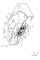
- FIG. 1 is a perspective view showing an appearance of an air blower according to an embodiment;
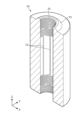
- FIG. It is a cross-sectional perspective view of the air blower which concerns on embodiment.
- 3 is an exploded perspective view of a bearing portion and a shaft according to the embodiment;
- FIG. It is a top view of the housing concerning an embodiment.
- FIG. 4 is a top view showing a state in which the sleeve according to the embodiment is accommodated in the recess of the housing; It is the perspective view which looked at the cap which concerns on embodiment from upper direction. It is the perspective view which looked at the cap which concerns on embodiment from the downward direction.
- It is a sectional view showing a bearing part concerning an embodiment.
- FIG. 5 is a cross-sectional view showing a bearing portion according to Modification 1;
- FIG. 11 is a cross-sectional view showing a bearing portion according to Modification 2;
- An air blower includes a housing having a recess opening upward, a sleeve having a first through-hole and arranged in the recess, and a second through-hole above the sleeve.
- a cap arranged in the a first clearance between the outer surface of the shaft and the inner surface of the sleeve; and a second clearance between the outer surface of the sleeve and the inner surface of the housing. is formed between the lower surface of the cap and the upper surface of the sleeve, and a third gap connected to the first gap and the second gap is formed between the outer surface of the cap and the sleeve.
- the first distance of the third gap which is the distance between or the distance between the outer surface of the sleeve and the cap, is the distance between the inner surface of the cap and the sleeve or the inner surface of the sleeve.
- the lubricating oil is accommodated in the first gap, the second gap, and the third gap, which are smaller than the second distance of the third gap, which is the distance between the cap and the cap.
- the first distance is narrower than the second distance. from to the first distance. Since the third gap is connected to the first gap and the second gap, the lubricating oil flows from the first gap to the second gap via the third gap due to the flow described above. This flow can prevent air bubbles in the lubricating oil from staying at a predetermined location, so it is possible to prevent the shaft and sleeve from being seized due to the air bubbles.
- the cap has a third through hole at a position facing the third gap.
- the lubricating oil in the third gap is connected to the outside by the third through hole provided in the cap.
- the air bubbles in the lubricating oil can be released from the third through hole to the outside of the cap. Therefore, it is possible to suppress clogging of the third gap with air bubbles, and it is possible to realize a stable flow of lubricating oil.
- the propeller has a cover portion that covers the third through hole from above, and blades that extend from the cover portion.
- the third through-hole is covered with the cover portion, it is possible to suppress the entry of dust or the like from the third through-hole.
- the outer surface of the sleeve or the inner surface of the housing has a cylindrical surface that forms the second gap.
- the outer surface of the sleeve or the inner surface of the housing also include a groove that forms the second gap.
- the second gap since the second gap includes a groove formed on the outer surface of the sleeve or a groove formed on the inner surface of the housing, these grooves can form a lubricating oil flow path. . This flow path allows the lubricating oil to flow smoothly.
- the lower end of the shaft is located below the lower surface of the sleeve, and a fourth gap connecting the first gap and the second gap is formed between the bottom surface of the recess and the lower surface of the sleeve. is preferably formed.
- the fourth gap connecting to the first gap and the second gap is formed between the bottom surface of the recess of the housing and the lower surface of the sleeve.
- Lubricating oil can be circulated in the order of the second gap and the third gap. This circulation facilitates the release of air bubbles in the lubricating oil to the outside, thereby further suppressing seizure.
- a third distance between the bottom surface of the recess and the lower surface of the sleeve in the fourth gap is a fourth distance between the outer surface of the sleeve and the inner surface of the housing in the second gap. It is preferable to make it larger than the distance.
- the third distance of the fourth gap is greater than the fourth distance of the second gap, so lubricating oil can flow smoothly from the fourth gap to the second gap. As a result, the lubricating oil flows smoothly in the circulation path, making it easier to release air bubbles to the outside.
- the cap protrudes upward from the housing.
- the cap protrudes upward from the housing, leakage of lubricating oil can be suppressed at the protruding portion. Therefore, it is possible to stably flow the lubricating oil for a long period of time.
- the outer surface of the shaft or the inner surface of the sleeve is formed with a guide groove for propelling the lubricating oil downward when the shaft rotates.
- the guide groove for propelling the lubricating oil downward when the shaft rotates is formed on the outer surface of the shaft or the inner surface of the sleeve, the lubricating oil flows from the first gap to the fourth gap. , or can be forced to flow from the third gap to the first gap. This allows the lubricating oil to flow more smoothly, making it easier to release air bubbles to the outside.
- the housing has a fixing portion for fixing the cap.
- the cap since the cap is fixed by the fixing portion of the housing, it is possible to prevent the cap from coming off and prevent leakage of lubricating oil. Moreover, if the cap is fixed, it is possible to suppress fluctuations in the first distance and the second distance of the third gap. Therefore, it is possible to stably flow the lubricating oil for a long period of time.
- the sleeve is cylindrical and fixed to the housing.
- the air bubbles can be released smoothly to the outside, and it is possible to suppress the seizure.
- the axial direction of the shaft provided in the blower is defined as the Z-axis direction
- the directions orthogonal to each other in a plane orthogonal to the Z-axis direction are defined as the X-axis direction and the Y-axis direction.
- the Z-axis direction may not be the vertical direction depending on the mode of use, the Z-axis direction will be described below for convenience of explanation.
- expressions that indicate relative directions or postures such as parallel and orthogonal also include cases where they are not strictly the directions or postures.
- two directions being parallel not only means that the two directions are completely parallel, but also being substantially parallel, that is, including a difference of about several percent, for example. means.
- FIG. 1 is a perspective view showing the appearance of fan 10 according to the embodiment.
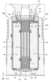
- FIG. 2 is a cross-sectional perspective view of the blower 10 according to the embodiment. Specifically, FIG. 2 is a cross-sectional perspective view of a cut plane including the II-II line in FIG.
- the blower 10 has a frame 20, a rotor portion 30, a stator portion 40, and a bearing portion 50.
- the frame 20 is a member that accommodates the rotor portion 30, the stator portion 40, and the bearing portion 50, and has a columnar opening 21 that opens vertically.
- a plurality of beams 22 (only one is shown in FIG. 2) extending from the inner edge of the opening 21 toward the center are radially arranged at the lower end of the opening 21 .
- a base 23 that holds the rotor portion 30 , the stator portion 40 and the bearing portion 50 is connected to the distal end portions of the plurality of beam portions 22 . That is, the base 23 is arranged in the central portion of the opening 21 .
- the rotor section 30 has a propeller 31 , a yoke 32 and magnets 33 .
- the propeller 31 has a bottomed cylindrical body portion 311 and a plurality of blades 312 extending outward from the periphery of the body portion 311 .
- the body part 311 has a bottom part 313 on the top and is formed in a cylindrical shape with an open bottom.
- a cylindrical yoke 32 is attached to the inner peripheral surface of the body portion 311 , and a cylindrical magnet 33 is attached to the inner peripheral surface of the yoke 32 .
- a columnar shaft 314 whose axial direction is the Z-axis direction is fixed to the central portion of the bottom portion 313 in plan view (viewed in the Z-axis direction).
- the stator section 40 is a section that generates a speed per hour according to the drive current.
- the stator section 40 has a stator core 41 , a plurality of coils 42 attached to the stator core 41 , and a circuit board 43 for supplying power to each coil 42 .
- the stator core 41 is made of, for example, laminated steel sheets in which electromagnetic steel sheets such as silicon steel sheets are laminated in the axial direction.
- the stator core 41 is directly or indirectly fixed to the base 23 .
- the stator core 41 has a plurality of teeth 411 projecting outward, and each coil 42 is attached to each tooth 411 . Thereby, the plurality of coils 42 are arranged at regular intervals in the circumferential direction around the stator core 41 .
- the plurality of coils 42 are a collection of wound conductor wires, and are electrically connected to a circuit board 43 arranged directly below each coil 42 .
- Each coil 42 is arranged inside the yoke 32 and the magnet 33 .
- the bearing portion 50 is a portion that rotatably supports the shaft 314 of the propeller 31 .
- FIG. 3 is an exploded perspective view of the bearing portion 50 and the shaft 314 according to the embodiment. As shown in FIG. 3, the bearing portion 50 has a housing 60, a sleeve 70 and a cap 80. As shown in FIG. 3, the bearing portion 50 has a housing 60, a sleeve 70 and a cap 80. As shown in FIG.
- the housing 60 is a member that houses a portion of the shaft 314, the sleeve 70 and the cap 80.
- FIG. 4 is a top view of the housing 60 according to the embodiment. As shown in FIGS. 3 and 4 , the housing 60 has a base portion 61 shaped like an elongated disk in a plan view, and a cylindrical portion 62 projecting upward from the base portion 61 .
- the cylindrical portion 62 is open at the top and has a bottom at the bottom end. Therefore, the inside of the cylindrical portion 62 is a columnar concave portion 63 having an opening upward.
- a pair of first housing grooves 64 extending from the top end to the bottom along the Z-axis direction are formed in the inner peripheral surface of the recess 63 at positions facing each other in the X-axis direction.
- a circular recess 631 is formed in the center of the bottom surface of the recess 63, and a receiving plate 632 (see FIG. 9) for receiving the tip of the shaft 314 is placed in this recess 631. are placed.
- a pair of second housing grooves 65 extending along the X-axis direction are formed in the bottom surface of the recess 63 to connect the first housing grooves 64 and the depression 631 .
- FIG. 5 is a cross-sectional perspective view of the sleeve 70 according to the embodiment. Specifically, FIG. 5 is a cross-sectional perspective view of a cut plane including line VV in FIG.
- the sleeve 70 is a cylindrical member, and a first through hole 71 extending in the Z-axis direction is formed in the center when viewed in the Z-axis direction.
- a shaft 314 is arranged in the first through hole 71 so as to pass through the first through hole 71 .
- a plurality of guide grooves 72 are formed on the inner peripheral surface (inner surface) of the sleeve 70 , that is, the inner peripheral surface forming the first through hole 71 .
- the plurality of guide grooves 72 are arranged at predetermined intervals in the circumferential direction.
- the upper and lower portions of each guide groove 72 are bent, and the intermediate portion is linear along the Z-axis direction.
- the upper and lower portions of each guide groove 72 have a refraction shape that tapers forward in the direction of rotation of the shaft 314.
- It's becoming Lubricating oil 90 (see FIG. 9) is filled between the shaft 314 and the sleeve 70, and when the shaft 314 rotates, the lubricating oil 90 is propelled downward by the shape of each guide groove 72 described above. be able to.
- the number or shape of the guide grooves 72 may be any as long as the lubricating oil 90 can be propelled downward.
- the outer peripheral surface (outer surface) of the sleeve 70 is a cylindrical surface.
- a protruding portion 73 protruding upward is formed around the first through hole 71 on the upper surface of the sleeve 70 .
- the outer peripheral surface of the projecting portion 73 is a tapered surface that tapers upward.
- a portion of the upper surface of the sleeve 70 other than the projecting portion 73 and the tip surface (upper surface) of the projecting portion 73 are flat surfaces.
- FIG. 6 is a top view showing a state in which the sleeve 70 according to the embodiment is accommodated in the recess 63 of the housing 60.
- FIG. 6 a plurality of crimped portions 74 are formed on the periphery of the upper surface of the sleeve 70 .
- a portion of the outer peripheral surface of the sleeve 70 is spread outward by each crimping portion 74 and is joined to the inner peripheral surface of the housing 60, and the first housing grooves 64 are not closed to such an extent that the first housing grooves 64 are not blocked. It is fitted inside.
- the sleeve 70 is thereby fixed within the recess 63 of the housing 60 .
- FIG. 7 is a perspective view of the cap 80 according to the embodiment viewed from above.
- FIG. 8 is a perspective view of the cap 80 according to the embodiment as seen from below.
- the cap 80 is a member formed in a cylindrical shape and has a second through hole 81 inside.
- the upper surface of the cap 80 is formed flat.
- a cap concave portion 82 is formed which is concave upward in the shape of a truncated cone.
- a pair of cap grooves 83 extending in the X-axis direction are formed in the lower surface of the cap 80 and the inner peripheral surface of the cap recess 82 at positions sandwiching the second through hole 81 .
- Each cap groove 83 is formed with a third through hole 84 penetrating to the upper surface of the cap 80 (see FIGS. 7 and 9).
- FIG. 9 is a cross-sectional view showing the bearing portion 50 according to the embodiment.
- FIG. 9 is a cross-sectional view of the shaft 314 along the axial direction.
- FIG. 9 shows a state in which a portion of shaft 314 , sleeve 70 and cap 80 are accommodated within housing 60 .
- the shaft 314 is illustrated with a two-dot chain line.
- a receiving plate 632, a sleeve 70, and a cap 80 are accommodated in this order from below.
- a disk-shaped receiving plate 632 is arranged in a recess 631 on the bottom surface of the recess 63 .
- This receiving plate 632 receives the lower end portion of the shaft 314 that has passed through the first through hole 71 of the sleeve 70 and the second through hole 81 of the cap 80 .
- the lower end of the shaft 314 is positioned below the lower surface of the sleeve 70 and contacts the receiving plate 632 . Since the lower end portion of the shaft 314 is formed in a spherical shape, the lower end portion and the receiving plate 632 are in contact with each other in a form close to point contact. Therefore, the shaft 314 can rotate smoothly.
- the sleeve 70 is arranged above the receiving plate 632 and fixed within the recess 63 by the crimped portions 74 described above.
- the cap 80 has its lower end housed in the recess 63 and its upper end protruding from the housing 60 . Specifically, the lower end of the cap 80 is fixed by being press-fitted into the recess 63 of the housing 60 .
- a portion of the housing 60 into which the lower end of the cap 80 is press-fitted is a fixing portion 67 (see FIG. 4) that fixes the cap 80 .
- the lower end of the cap 80 is press-fitted and fixed to a portion other than the first housing grooves 64 on the entire circumference of the upper end of the recess 63 of the housing 60 , so that the portion becomes the fixing portion 67 .
- the fixing portion 67 may take any form as long as it can fix the cap 80 .
- it may be a fixing portion that employs caulking or a fixing portion that fixes the cap 80 with another member.
- the portions of the lower end of the cap 80 corresponding to the first housing grooves 64 are separated from the housing 60, so that the first housing grooves 64 are connected to the external space (see circle C in FIG. 9).
- a first gap S1 is formed between the outer peripheral surface (outer surface) of the shaft 314 and the inner peripheral surface (inner surface) of the sleeve 70 . Specifically, a pair of first gaps S1 are provided with the shaft 314 interposed therebetween.
- a second gap S2 is formed between the outer peripheral surface (outer surface) of the sleeve 70 and the inner peripheral surface (inner surface) of the recess 63 of the housing 60 . Specifically, a pair of second gaps S2 are provided with the sleeve 70 interposed therebetween. Each second gap S2 includes a first housing groove 64 formed in the inner peripheral surface of the recess 63. As shown in FIG. The second gap S2 extends in the Z-axis direction in a generally uniform shape in a cross-sectional view.
- a third gap S3 is formed between the lower surface of the cap 80 and the upper surface of the sleeve 70 to connect the first gap S1 and the second gap S2. Specifically, a pair of third gaps S3 are provided with the shaft 314 interposed therebetween. Each third gap S3 includes a cap groove 83 formed in the bottom surface of the cap 80. As shown in FIG.
- a fourth gap S4 is formed which is connected to the first gap S1 and the second gap S2. Specifically, a pair of fourth gaps S4 are provided with the shaft 314 interposed therebetween.
- Each fourth gap S4 includes a second housing groove 65 formed in the bottom surface of the recess 63. As shown in FIG.
- a lubricating oil 90 is contained in the concave portion 63 of the housing 60 .
- the lubricating oil 90 is illustrated by dot hatching.
- the lubricating oil 90 is also contained in the first gap S1, the second gap S2, the third gap S3 and the fourth gap S4.
- the lubricating oil 90 is also contained in the second through hole 81 and each third through hole 84 of the cap 80 .
- a connecting portion 315 protruding downward is formed in the central portion of the lower surface of the main body portion 311 of the propeller 31 .
- the connecting portion 315 is a portion to which the upper end portion of the shaft 314 is fitted and connected.
- the body portion 311 is arranged above each third through hole 84 and covers each third through hole 84 from above. That is, the body portion 311 is an example of a cover portion that covers the third through holes 84 from above.
- the rotation of the shaft 314 causes the lubricating oil 90 in the recess 63 of the housing 60 to flow through the first gap S1, the fourth gap S4, the second gap S2 and the third gap S3.
- a propulsive force caused by the guide grooves 72 of the sleeve 70 acts on the lubricating oil 90 within the first gap S1.
- a downward flow is generated in the lubricating oil 90 within the first gap S1.
- the lubricating oil 90 flowing downward in the first gap S1 enters the fourth gap S4.
- the lubricating oil 90 flows radially outward of the recess 63 in the second housing groove 65 included in the fourth gap S4 and enters the second gap S2.
- the lubricating oil 90 flows upward in the first housing groove 64 included in the second gap S2 and enters the third gap S3.
- the lubricating oil 90 flows radially inward of the recess 63 through the cap groove 83 included in the third gap S3 and enters the first gap S1.
- the lubricating oil 90 circulates through the first gap S1, the fourth gap S4, the second gap S2, and the third gap S3.
- the first gap S1, the second housing groove 65, the first housing groove 64 and the cap groove 83 form a circulation path.
- the lubricating oil 90 circulates in the recess 63 of the housing 60 in this way, it is possible to prevent the air bubbles B contained in the lubricating oil 90 from remaining in each gap.
- the air bubbles B are discharged outward from the third through holes 84 of the cap 80 and the first housing grooves 64 .
- the third through hole 84 is formed to have a cross-sectional shape that maintains the surface tension of the lubricating oil 90 .
- each first housing groove 64 is also formed to have a cross-sectional shape that maintains the surface tension. This suppresses leakage of the lubricating oil 90 from the third through-hole 84 and the first housing grooves 64 .
- the first distance t1 is the distance between the tip end surface of the projecting portion 73 of the sleeve 70 and the inner top surface of the cap recessed portion 82 of the cap 80 .
- the second distance t2 is the distance between the upper surface of the sleeve 70 other than the protrusion 73 and the lower surface of the cap 80 other than the cap recess 82 . If the distance between the inner peripheral surface of the protrusion 73 of the sleeve 70 and the inner peripheral surface of the cap recess 82 of the cap 80 is between the first distance t1 and the second distance t2, smoother circulation can be achieved. It is preferable to realize
- a third distance t3 between the bottom surface of the recess 63 and the bottom surface of the sleeve 70 in the fourth gap S4 is greater than a fourth distance t4 between the outer peripheral surface of the sleeve 70 and the inner peripheral surface of the recess 63 in the second gap S2. is preferable for achieving smoother circulation. Furthermore, if the first distance t1 ⁇ the second distance t2 ⁇ the fourth distance t4 ⁇ the third distance t3, it is preferable to achieve even smoother circulation.
- the blower 10 includes the housing 60 having the recess 63 opening upward, the sleeve 70 having the first through-hole 71 and arranged in the recess 63, and the second through-hole A cap 80 having a hole 81 and disposed above the sleeve 70, a shaft 314 passing through the first through hole 71 and the second through hole 81, a propeller 31 connected to the upper end of the shaft 314, and lubricating oil. 90.
- a lower end portion of the cap 80 is accommodated within the recess 63 .
- a first gap S1 is formed between the outer peripheral surface (outer surface) of the shaft 314 and the inner peripheral surface (inner surface) of the sleeve 70 .
- a second gap S2 is formed between the outer peripheral surface (outer surface) of the sleeve 70 and the inner peripheral surface (inner surface) of the housing 60 .
- a third gap S3 is formed between the lower surface of the cap 80 and the upper surface of the sleeve 70 to connect the first gap S1 and the second gap S2.
- Lubricating oil 90 is accommodated in the first gap S1, the second gap S2 and the third gap S3.
- the lubricating oil 90 easily flows from the second distance t2 toward the first distance t1 within the third gap S3, thereby enabling smooth circulation as a whole. If the lubricating oil 90 circulates smoothly, the air bubbles B in the lubricating oil 90 can be suppressed from remaining at a predetermined location, and the burning between the shaft 314 and the sleeve 70 caused by the air bubbles B can be suppressed. is possible.
- the cap 80 also has a third through hole 84 at a position facing the third gap S3.
- the lubricating oil 90 in the third gap S3 is connected to the outside through the third through hole 84 provided in the cap 80.
- the air bubbles B in the lubricating oil 90 can be released from the third through-hole 84 to the outside of the cap 80 . Therefore, it is possible to prevent the air bubbles B from clogging the third gap S3, and realize stable circulation.
- the air bubbles B since the air bubbles B are released to the outside, the air bubbles B mixed in the lubricating oil 90 can be reduced, and as a result, it is possible to further suppress the occurrence of seizure between the shaft 314 and the sleeve 70. .
- the propeller 31 also has a body portion 311 (cover portion) that covers the third through hole 84 from above, and blades 312 that extend from the body portion 311 .
- the third through-hole 84 is covered with the main body portion 311, it is possible to suppress the entry of dust or the like from the third through-hole 84.
- the outer surface of the sleeve 70 has a cylindrical surface that forms the second gap S2.
- the outer surface of the sleeve 70 has a cylindrical surface that forms the second gap S2, so that the step in the second gap S2 can be reduced and the retention of the air bubbles B can be suppressed. This allows the air bubbles B to flow smoothly together with the lubricating oil 90 in the second gap S2.
- the inner peripheral surface of the housing 60 includes a first housing groove 64 (groove) that forms the second gap S2.
- the second gap S2 includes the first housing groove 64 formed in the inner peripheral surface of the housing 60, the first housing groove 64 can form a flow path for the lubricating oil 90. .
- This flow path allows the lubricating oil 90 to flow smoothly.
- the lower end of the shaft 314 is located below the lower surface of the sleeve 70, and a fourth gap connecting the first gap S1 and the second gap S2 is formed between the bottom surface of the recess 63 and the lower surface of the sleeve 70. S4 is formed.
- the fourth gap S4 connected to the first gap S1 and the second gap S2 is formed between the bottom surface of the recess 63 of the housing 60 and the lower surface of the sleeve 70, the first gap S1 is formed.
- the lubricating oil 90 can be circulated in the order of the fourth gap S4, the second gap S2 and the third gap S3. This circulation facilitates the release of air bubbles in the lubricating oil 90 to the outside, thereby further suppressing seizure.
- the third distance t3 between the bottom surface of the recess 63 and the bottom surface of the sleeve 70 in the fourth gap S4 is the fourth distance between the outer peripheral surface of the sleeve 70 and the inner peripheral surface of the housing 60 in the second gap S2. larger than t4.
- the lubricating oil 90 can flow smoothly from the fourth gap S4 to the second gap S2. can. As a result, the lubricating oil 90 flows smoothly in the circulation path, making it easier to release the air bubbles B to the outside.
- the cap 80 protrudes upward from the housing 60 .
- the cap 80 protrudes upward from the housing 60, leakage of the lubricating oil 90 can be suppressed at the protruding portion. Therefore, it is possible to stably flow the lubricating oil 90 for a long period of time.
- a guide groove 72 is formed on the inner peripheral surface of the sleeve 70 to propel the lubricating oil 90 downward when the shaft 314 rotates.
- the guide groove 72 for propelling the lubricating oil 90 downward when the shaft 314 rotates is formed in the inner peripheral surface of the sleeve 70, the lubricating oil 90 flows from the first gap S1 to the fourth gap. It can be forced to flow into the gap S4 or from the third gap S3 to the first gap S1. This allows the lubricating oil 90 to flow more smoothly, making it easier to release the air bubbles B to the outside.
- the housing 60 has a fixing portion 67 for fixing the cap 80 .
- the cap 80 since the cap 80 is fixed by the fixing portion 67 of the housing 60, it is possible to prevent the cap 80 from coming off and to prevent the leakage of the lubricating oil 90. In addition, if the cap 80 is fixed, it is possible to suppress fluctuations in the first distance t1 and the second distance t2 of the third gap S3. Therefore, it is possible to stably flow the lubricating oil 90 for a long period of time.
- the sleeve 70 is cylindrical and fixed to the housing 60 .
- the air bubbles B can be smoothly released to the outside, and burning can be suppressed.
- blower 10 according to the present embodiment has been described above, the present invention is not limited to the above embodiment.
- the embodiments disclosed this time are illustrative in all respects and are not restrictive, and the scope of the present invention includes all modifications within the meaning and range of equivalents to the claims. .
- parts equivalent to those in the above-described embodiment may be denoted by the same reference numerals, and the description thereof may be omitted.
- FIG. 10 is a cross-sectional view showing a bearing portion 50a according to Modification 1.
- FIG. 10 is a diagram corresponding to FIG.
- the lower surface of the sleeve 70a provided in the bearing portion 50a is in contact with the bottom surface of the housing 60, and the fourth gap (second housing groove) is not provided.
- a pair of through-holes 79 for circulation extending through the inner peripheral surface and the outer peripheral surface of the sleeve 70a are provided in the lower portion of the sleeve 70a in the radial direction.
- the pair of through-holes 79 for circulation are arranged in a straight line and are connected to the first gap S1 and the second gap S2, respectively.
- Each circulation through-hole 79 forms a part of the circulation path of the lubricating oil 90 .
- the bearing portion may be provided with neither the fourth gap S4 nor the through hole 79 for circulation.
- the second distance t2 may be set to a size that causes capillary action.
- air bubbles B may enter the lubricating oil 90 .
- the lubricating oil 90 flows from the second distance t2 toward the first distance t1 within the third gap S3.
- the lubricating oil 90 flows from the first gap S1 to the second gap S2 through the third gap S3 due to the flow described above. and flow.
- This flow can prevent the air bubbles B in the lubricating oil 90 from remaining at a predetermined location. Therefore, it is possible to suppress seizure between the shaft 314 and the sleeve 70 caused by the bubble B.
- FIG. 11 is a cross-sectional view showing a bearing portion 50b according to Modification 2. As shown in FIG. Specifically, FIG. 11 is a diagram corresponding to FIG. As shown in FIG. 11, the recessed portion 63b of the housing 60b has a rectangular shape, and the inner peripheral surface thereof is a cylindrical surface. That is, no first housing groove is formed in the recess 63b.
- a pair of sleeve grooves 75 (grooves) extending axially from the upper end to the lower end of the sleeve 70b are formed on the outer peripheral surface of the sleeve 70b.
- Each sleeve groove 75 is included in the second gap S2 and forms a part of the circulation path.
- the cap 80 is press-fitted and fixed to the entire periphery of the upper end of the recess 63b. That is, in this case, the entire periphery of the upper end portion of the concave portion 63b becomes the fixing portion 67b.
- the first housing groove may be provided on the inner peripheral surface of the concave portion of the housing, and the sleeve groove may be provided on the outer peripheral surface of the sleeve.
- the guide groove 72 is formed on the inner peripheral surface of the sleeve 70 as an example, but the guide groove may be formed on the outer peripheral surface of the shaft 314 .
- the cap 80 formed in a cylindrical shape was exemplified, but the cap may have a flange portion in which the upper end portion projects radially outward from the lower end portion.
- the flange portion can cover the concave portion of the housing from above, it is possible to suppress the leakage of lubricating oil.
- the distance between the outer surface of the cap 80 and the sleeve 70 and the distance between the outer surface of the sleeve 70 and the cap 80 are the same.
- the distance between the outer surface of cap 80 and sleeve 70 and the distance between the outer surface of sleeve 70 and cap 80 may be different.
- an appropriate distance may be selected as the first distance t1 through experiments, simulations, or the like.
- the case where the distance between the inner surface of the cap 80 and the sleeve 70 and the distance between the inner surface of the sleeve 70 and the cap 80 are the same is exemplified.
- the distance between the inner surface of cap 80 and sleeve 70 and the distance between the inner surface of sleeve 70 and cap 80 may be different.
- an appropriate distance may be selected as the second distance t2 through experiments, simulations, or the like.
- the present disclosure is useful, for example, for blowers built into electronic devices.
Landscapes
- Engineering & Computer Science (AREA)
- Mechanical Engineering (AREA)
- General Engineering & Computer Science (AREA)
- Sliding-Contact Bearings (AREA)
- Structures Of Non-Positive Displacement Pumps (AREA)
Abstract
送風機は、凹部を有するハウジングと、第一貫通孔を有し、凹部内に配置されたスリーブと、第二貫通孔を有し、スリーブの上方に配置されたキャップと、第一貫通孔及び第二貫通孔を貫通するシャフトと、シャフトに接続されたプロペラと、凹部内に収容された潤滑油とを備えている。シャフトの外側面とスリーブの内側面との間に第一隙間が形成されている。スリーブの外側面とハウジングの内側面との間に第二隙間が形成されている。キャップの下面とスリーブの上面との間に第三隙間が形成されている。キャップの外側面とスリーブとの間の距離である第三隙間の第一距離は、キャップの内側面とスリーブとの間の距離である第三隙間の第二距離よりも小さい。
Description
本開示は、送風機に関する。
従来、ノートパソコンなどの電子機器に搭載される送風機においては、シャフトと、当該シャフトを回転自在に保持するスリーブとの間に潤滑油が充填されている(例えば特許文献1参照)。
潤滑油内に気泡が含まれていると、その気泡を起因としてシャフトとスリーブとが直接的に接触してしまい、焼き付けを発生させるおそれがある。
そこで、本開示の目的は、焼き付けの発生を抑制することができる送風機を提供することである。
本開示の一態様に係る送風機は、上方に開口する凹部を有するハウジングと、第一貫通孔を有し、前記凹部内に配置されたスリーブと、第二貫通孔を有し、前記スリーブの上方に配置されたキャップと、前記第一貫通孔及び前記第二貫通孔を貫通するシャフトと、前記シャフトの上端に接続されたプロペラと、潤滑油と、を備え、前記キャップの下端部は、前記凹部内に収容されており、前記シャフトの外側面と前記スリーブの内側面との間に第一隙間が形成されており、前記スリーブの外側面と前記ハウジングの内側面との間に第二隙間が形成されており、前記キャップの下面と前記スリーブの上面との間に、前記第一隙間及び前記第二隙間に繋がる第三隙間が形成されており、前記キャップの外側面と前記スリーブとの間の距離または前記スリーブの前記外側面と前記キャップとの間の距離である前記第三隙間の第一距離は、前記キャップの内側面と前記スリーブとの間の距離または前記スリーブの前記内側面と前記キャップとの間の距離である前記第三隙間の第二距離よりも小さく、前記第一隙間、前記第二隙間及び前記第三隙間には、前記潤滑油が収容されている。
本開示の一態様に係る送風機によれば、焼き付けの発生を抑制することができる。
本開示の一態様に係る送風機は、上方に開口する凹部を有するハウジングと、第一貫通孔を有し、前記凹部内に配置されたスリーブと、第二貫通孔を有し、前記スリーブの上方に配置されたキャップと、前記第一貫通孔及び前記第二貫通孔を貫通するシャフトと、前記シャフトの上端に接続されたプロペラと、潤滑油と、を備え、前記キャップにおける下端部は、前記凹部内に収容されており、前記シャフトの外側面と前記スリーブの内側面との間に第一隙間が形成されており、前記スリーブの外側面と前記ハウジングの内側面との間に第二隙間が形成されており、前記キャップの下面と前記スリーブの上面との間に、前記第一隙間及び前記第二隙間に繋がる第三隙間が形成されており、前記キャップの外側面と前記スリーブとの間の距離または前記スリーブの前記外側面と前記キャップとの間の距離である前記第三隙間の第一距離は、前記キャップの内側面と前記スリーブとの間の距離または前記スリーブの前記内側面と前記キャップとの間の距離である前記第三隙間の第二距離よりも小さく、前記第一隙間、前記第二隙間及び前記第三隙間には、前記潤滑油が収容されている。
これによれば、潤滑油が収容されている第三隙間では、第一距離が第二距離よりも狭いために、この大きさの差を起因として、第三隙間内では潤滑油が第二距離から第一距離へと向かってスムーズに流れることとなる。第三隙間は第一隙間及び第二隙間に繋がっているので、これらの中では前述した流れにより、潤滑油が第一隙間から第三隙間を介して第二隙間へと流れることになる。この流れにより潤滑油内の気泡が所定の箇所で留まることを抑制できるので、気泡を起因としたシャフトとスリーブとの焼き付けの発生を抑制することが可能である。
また、前記キャップは、前記第三隙間に対向する位置に第三貫通孔を有すると好ましい。
これによれば、キャップに備わる第三貫通孔により、第三隙間内の潤滑油が外部に繋がることになる。これにより、潤滑油内の気泡を第三貫通孔からキャップ外へと放出することができる。したがって、気泡が第三隙間をつまらせることを抑制でき、安定した潤滑油の流れを実現することができる。
また、前記プロペラは、前記第三貫通孔を上方から覆うカバー部と、前記カバー部から延びる羽根と、を有すると好ましい。
これによれば、第三貫通孔がカバー部により覆われているので、第三貫通孔から埃等が侵入することを抑制できる。
また、前記スリーブの前記外側面または前記ハウジングの前記内側面は、前記第二隙間を形成する円筒面を有すると好ましい。
シャフトの軸方向に沿う断面視において、第二隙間に段差等があると、その段差部に気泡が滞留してしまうおそれがある。本態様では、スリーブの外側面またはハウジングの内側面が、第二隙間を形成する円筒面を有しているので、第二隙間内の段差を低減することができ、気泡の滞留を抑制できる。これにより、第二隙間においては潤滑油とともに気泡をスムーズに流すことができる。
また、前記スリーブの前記外側面または前記ハウジングの前記内側面は、前記第二隙間を形成する溝を含んでもいると好ましい。
これによれば、第二隙間は、スリーブの外側面に形成された溝またはハウジングの内側面に形成された溝を含んでいるので、これらの溝により潤滑油の流路を形成することができる。この流路によって潤滑油の流れをスムーズにすることができる。
また、前記シャフトの下端部は、前記スリーブの下面よりも下方に位置しており、前記凹部の底面と前記スリーブの下面との間に、前記第一隙間及び前記第二隙間に繋がる第四隙間が形成されていていると好ましい。
これによれば、ハウジングの凹部の底面とスリーブの下面との間に、第一隙間及び第二隙間に繋がる第四隙間が形成されているので、第一隙間を起点とすると、第四隙間、第二隙間及び第三隙間という順に潤滑油を循環させることができる。この循環により潤滑油内の気泡が外方へと放出させやすくなるので、より焼き付けを抑制することができる。
また、前記第四隙間において前記凹部の底面と前記スリーブの前記下面との間の第三距離は、前記第二隙間において前記スリーブの前記外側面と前記ハウジングの前記内側面との間の第四距離よりも大きくすると好ましい。
これによれば、第四隙間の第三距離は、第二隙間の第四距離よりも大きいので、第四隙間から第二隙間へとスムーズに潤滑油を流すことができる。結果的に、循環路中での潤滑油の流れがスムーズとなり、より気泡を外方に放出させやすくなる。
また、前記キャップは、前記ハウジングから上方に突出していると好ましい。
これによれば、キャップがハウジングから上方に突出しているので、当該突出部分で潤滑油の漏れを抑制することができる。したがって、潤滑油を長期的に安定して流すことが可能である。
また、前記シャフトの前記外側面または前記スリーブの前記内側面には、前記シャフトの回転時に前記潤滑油を下方へと推進させるガイド溝が形成されていていると好ましい。
これによれば、シャフトの回転時に潤滑油を下方へと推進させるためのガイド溝が、シャフトの外側面またはスリーブの内側面に形成されているので、潤滑油を第一隙間から第四隙間へ、または第三隙間から第一隙間へと強制的に流すことができる。これによって、よりスムーズに潤滑油を流すことができ、気泡を外方へと放出させやすくなる。
また、前記ハウジングは、前記キャップを固定する固定部を有していると好ましい。
これによれば、ハウジングの固定部によりキャップが固定されているので、キャップの抜けを抑制でき、潤滑油の漏れも抑制できる。また、キャップが固定されていれば、第三隙間の第一距離及び第二距離が変動してしまうことを抑制できる。したがって、潤滑油を長期的に安定して流すことが可能である。
また、前記スリーブは円筒状であり、前記ハウジングに固定されていていると好ましい。
これによれば、円筒状のスリーブがハウジングに固定された送風機においても、気泡をスムーズに外方へと放出でき、焼き付けを抑制することが可能である。
(実施の形態)
以下、図面を参照しながら、本発明の実施の形態(その変形例も含む)に係る送風機について説明する。なお、以下で説明する実施の形態は、いずれも包括的または具体的な例を示すものである。以下の実施の形態で示される数値、形状、材料、構成要素、構成要素の配置位置及び接続形態等は、一例であり、本発明を限定する主旨ではない。各図において、寸法等は厳密に図示したものではない。各図において、同一または同様な構成要素については同じ符号を付している。
以下、図面を参照しながら、本発明の実施の形態(その変形例も含む)に係る送風機について説明する。なお、以下で説明する実施の形態は、いずれも包括的または具体的な例を示すものである。以下の実施の形態で示される数値、形状、材料、構成要素、構成要素の配置位置及び接続形態等は、一例であり、本発明を限定する主旨ではない。各図において、寸法等は厳密に図示したものではない。各図において、同一または同様な構成要素については同じ符号を付している。
以下の説明及び図面中において、送風機に備わるシャフトの軸方向をZ軸方向と定義し、Z軸方向に直交する平面内において互いに直交する各方向を、X軸方向及びY軸方向と定義する。なお、使用態様によってはZ軸方向が上下方向にならない場合も考えられるが、以下では説明の便宜のため、Z軸方向を上下方向として説明する。
以下の説明において、平行及び直交などの、相対的な方向または姿勢を示す表現は、厳密には、その方向または姿勢ではない場合も含む。例えば、2つの方向が平行であるとは、当該2つの方向が完全に平行であることを意味するだけでなく、実質的に平行であること、すなわち、例えば数%程度の差異を含むことも意味する。
[送風機の構成]
まず、実施の形態に係る送風機10の概要について説明する。図1は、実施の形態に係る送風機10の外観を示す斜視図である。図2は、実施の形態に係る送風機10の断面斜視図である。具体的には、図2は、図1におけるII-II線を含む切断面を見た断面斜視図である。
まず、実施の形態に係る送風機10の概要について説明する。図1は、実施の形態に係る送風機10の外観を示す斜視図である。図2は、実施の形態に係る送風機10の断面斜視図である。具体的には、図2は、図1におけるII-II線を含む切断面を見た断面斜視図である。
図1~図2に示すように、実施の形態に係る送風機10は、フレーム20と、ロータ部30と、ステータ部40と、軸受部50とを有している。
フレーム20は、ロータ部30と、ステータ部40と、軸受部50と収容する部材であり、上下方向に開放した円柱状の開口部21を有している。開口部21内における下端部は、開口部21の内縁から中央に向けて延びる複数の梁部22(図2では1つのみ図示)が放射状に配置されている。複数の梁部22の先端部には、ロータ部30、ステータ部40及び軸受部50を保持する基台23が連結されている。つまり、基台23は、開口部21の中央部に配置されている。
ロータ部30は、プロペラ31と、ヨーク32と、マグネット33とを有している。プロペラ31は、有底円筒状の本体部311と、本体部311の周囲から外方に延びる複数の羽根312とを有している。
本体部311は、上方に底部313を有し、下方が開放された円筒状に形成されている。本体部311の内周面には、円筒状のヨーク32が取り付けられており、このヨーク32の内周面には、円筒状のマグネット33が取り付けられている。底部313において平面視(Z軸方向視)の中央部には、Z軸方向を軸方向とする円柱状のシャフト314が固定されている。
ステータ部40は、駆動電流に応じて時速を発生される部位である。ステータ部40は、ステータコア41と、当該ステータコア41に取り付けられた複数のコイル42と、各コイル42に電力を供給するための回路基板43とを有している。ステータコア41は、例えば、珪素鋼板等の電磁鋼板が軸方向に積層された積層鋼板からなる。ステータコア41は、基台23に直接的あるいは間接的に固定されている。ステータコア41は、外方に向けて突出した複数のティース411を有しており、この各ティース411に対して各コイル42が取り付けられている。これにより、複数のコイル42は、ステータコア41を中心にした周方向に等間隔で配置されている。複数のコイル42は、巻回された導線の集合体であり、各コイル42の直下に配置された回路基板43に対して電気的に接続されている。各コイル42は、ヨーク32及びマグネット33の内方に配置されている。
次に軸受部50について詳細に説明する。軸受部50は、プロペラ31のシャフト314を回転自在に支持する部位である。図3は、実施の形態に係る軸受部50及びシャフト314の分解斜視図である。図3に示すように、軸受部50は、ハウジング60と、スリーブ70と、キャップ80とを有している。
ハウジング60は、シャフト314の一部とスリーブ70とキャップ80とを収容する部材である。図4は、実施の形態に係るハウジング60の上面図である。図3及び図4に示すように、ハウジング60は、平面視長円板状の基部61と、基部61から上方に突出した円筒状の筒部62とを有している。筒部62は、上方が開放され、下方の端部が底となっている。このため、筒部62の内部が、上方に開口を有した円柱状の凹部63である。凹部63の内周面には、X軸方向で対向する位置に、上端部から底までZ軸方向に沿って延びる一対の第一ハウジング溝64が形成されている。
図4に示すように、凹部63の底面の中央部には円形状の窪み631が形成されており、この窪み631内には、シャフト314の先端部を受ける受け板632(図9参照)が配置されている。凹部63の底面には、各第一ハウジング溝64と窪み631とを繋ぐため、X軸方向に沿って延びる一対の第二ハウジング溝65が形成されている。
図5は、実施の形態に係るスリーブ70の断面斜視図である。具体的には図5は、図3におけるV-V線を含む切断面を見た断面斜視図である。図3及び図5に示すように、スリーブ70は、円筒状の部材であり、Z軸方向視の中心部に、Z軸方向に延びる第一貫通孔71が形成されている。この第一貫通孔71内にはシャフト314が当該第一貫通孔71を貫通するように配置される。スリーブ70の内周面(内側面)、つまり第一貫通孔71をなす内周面には、複数のガイド溝72が形成されている。複数のガイド溝72は、周方向に所定の間隔をあけて配置されている。各ガイド溝72における上部及び下部は、屈折した形状となっており、その中間部ではZ軸方向に沿う直線状となっている。例えばシャフト314が、Z軸プラス方向視(上面視)において反時計回りで回転する場合には、各ガイド溝72の上部及び下部では、シャフト314の回転方向の先方に向かうほど先細る屈折形状となっている。シャフト314とスリーブ70との間には、潤滑油90(図9参照)が、充填されるが、シャフト314が回転すると、前述した各ガイド溝72の形状によって潤滑油90が下方へと推進させることができる。なお、ガイド溝72の設置個数またはその形状は、潤滑油90を下方へ推進させることができるのであれば、如何様でもよい。
スリーブ70の外周面(外側面)は寸胴であり円筒面となっている。スリーブ70の上面において第一貫通孔71の周囲には、上方に突出した突出部73が形成されている。突出部73の外周面は、上方に向けて先細るテーパ面となっている。スリーブ70の上面において突出部73以外の部分と、突出部73の先端面(上面)は平坦面となっている。
図6は、実施の形態に係るスリーブ70がハウジング60の凹部63に収容された状態を示す上面図である。図6に示すように、スリーブ70の上面の周縁部には、複数のカシメ部74が形成されている。各カシメ部74によって、スリーブ70の外周面の一部が外方に広げられて、ハウジング60の内周面に接合されたり、各第一ハウジング溝64を閉塞しない程度に当該第一ハウジング溝64内に嵌合されたりしている。これにより、スリーブ70がハウジング60の凹部63内で固定されている。
図7は、実施の形態に係るキャップ80を上方から見た斜視図である。図8は、実施の形態に係るキャップ80を下方から見た斜視図である。図7及び図8に示すように、キャップ80は、円筒状に形成された部材であり、その内部が第二貫通孔81となっている。キャップ80の上面は平坦状に形成されている。一方、キャップ80の下面において、第二貫通孔81の周囲には、上方に向けて円錐台状に凹んだキャップ凹部82が形成されている。また、キャップ80の下面及びキャップ凹部82の内周面には、第二貫通孔81を挟む位置にX軸方向に沿う一対のキャップ溝83が形成されている。各キャップ溝83には、キャップ80の上面まで貫通する第三貫通孔84が形成されている(図7及び図9参照)。
図9は、実施の形態に係る軸受部50を示す断面図である。図9は、シャフト314の軸方向に沿う断面を見た図である。図9では、ハウジング60内に、シャフト314の一部と、スリーブ70と、キャップ80とを収容した状態を示している。図9では、シャフト314を二点鎖線で図示している。図9に示すように、ハウジング60の凹部63内には、下方から順に受け板632、スリーブ70、キャップ80が収容されている。具体的には、凹部63の底面の窪み631内には、円板状の受け板632が配置されている。この受け板632は、スリーブ70の第一貫通孔71及びキャップ80の第二貫通孔81を貫通したシャフト314の下端部を受けている。シャフト314の下端部は、スリーブ70の下面よりも下方に位置しており、受け板632に接触している。シャフト314の下端部は球面状に形成されているため、当該下端部と受け板632とは点接触に近い形態で接触している。したがって、シャフト314がスムーズに回転できるようになっている。
スリーブ70は、受け板632の上方に配置されており、上述した各カシメ部74によって凹部63内で固定されている。キャップ80は、その下端部が凹部63内に収容されていて、上端部がハウジング60から突出している。具体的には、キャップ80の下端部は、ハウジング60の凹部63内に圧入されることで固定されている。ハウジング60において、キャップ80の下端部が圧入される箇所が、キャップ80を固定する固定部67(図4参照)である。具体的には、ハウジング60の凹部63の上端部全周において、各第一ハウジング溝64以外の箇所に対してキャップ80の下端部が圧入され固定されるので、当該箇所が固定部67となる。なお、固定部67は、キャップ80を固定できるのであればその態様は如何様でもよい。例えば、カシメを採用した固定部や、他の部材でキャップ80を固定する固定部であってもよい。キャップ80の下端部において各第一ハウジング溝64に対応する箇所は、ハウジング60から離間しているので、各第一ハウジング溝64は外部空間と繋がっている(図9の円C参照)。
シャフト314の外周面(外側面)と、スリーブ70の内周面(内側面)との間には、第一隙間S1が形成されている。具体的には、第一隙間S1は、シャフト314を挟んで一対設けられている。
スリーブ70の外周面(外側面)と、ハウジング60の凹部63の内周面(内側面)との間には、第二隙間S2が形成されている。具体的には、第二隙間S2は、スリーブ70を挟んで一対設けられている。各第二隙間S2は、凹部63の内周面に形成された第一ハウジング溝64を含んでいる。第二隙間S2は、断面視において全体として一様な形状でZ軸方向に延びている。
キャップ80の下面と、スリーブ70の上面との間には、第一隙間S1及び第二隙間S2に繋がる第三隙間S3が形成されている。具体的には、第三隙間S3は、シャフト314を挟んで一対設けられている。各第三隙間S3は、キャップ80の下面に形成されたキャップ溝83を含んでいる。
スリーブ70の下面と、ハウジング60の凹部63の底面との間には、第一隙間S1及び第二隙間S2に繋がる第四隙間S4が形成されている。具体的には、第四隙間S4は、シャフト314を挟んで一対設けられている。各第四隙間S4は、凹部63の底面に形成された第二ハウジング溝65を含んでいる。
ハウジング60の凹部63内には、潤滑油90が収容されている。図9において潤滑油90はドットハッチングで図示している。潤滑油90は、第一隙間S1、第二隙間S2、第三隙間S3及び第四隙間S4内にも収容されている。潤滑油90は、キャップ80の第二貫通孔81及び各第三貫通孔84内にも収容されている。
プロペラ31の本体部311において下面中央部には、下方に向けて突出した接続部315が形成されている。接続部315は、シャフト314の上端部が嵌め込まれ接続される部位である。本体部311は、各第三貫通孔84の上方に配置されており、各第三貫通孔84を上方から覆っている。つまり、本体部311は、各第三貫通孔84を上方から覆うカバー部の一例である。
[動作]
次に、送風機10の動作について説明する。送風機10の各コイル42に電流が供給されると、各ティース411に磁束が発生する。そして、ティース411とマグネット33との間の磁束の作用により、ステータ部40とロータ部30との間に周方向のトルクが生じる。その結果、プロペラ31がシャフト314を中心にして回転し、各羽根312によって気流が発生することになる。軸受部50においては、回転するシャフト314を安定的に支持している。
次に、送風機10の動作について説明する。送風機10の各コイル42に電流が供給されると、各ティース411に磁束が発生する。そして、ティース411とマグネット33との間の磁束の作用により、ステータ部40とロータ部30との間に周方向のトルクが生じる。その結果、プロペラ31がシャフト314を中心にして回転し、各羽根312によって気流が発生することになる。軸受部50においては、回転するシャフト314を安定的に支持している。
シャフト314の回転により、ハウジング60の凹部63内の潤滑油90には、第一隙間S1、第四隙間S4、第二隙間S2及び第三隙間S3を循環する流れが生じる。具体的には、シャフト314の回転によって、第一隙間S1内では、スリーブ70の各ガイド溝72を起因とした推進力が潤滑油90に作用する。これにより第一隙間S1内では下方に向かう流れが潤滑油90に生じる。第一隙間S1内で下方に向かって流れた潤滑油90は、第四隙間S4に進入する。潤滑油90は、第四隙間S4に含まれる第二ハウジング溝65内を、凹部63の径方向外方に向けて流れて第二隙間S2に進入する。潤滑油90は、第二隙間S2に含まれる第一ハウジング溝64内を、上方に向けて流れて第三隙間S3に進入する。潤滑油90は、第三隙間S3に含まれるキャップ溝83内を凹部63の径方向内方に向けて流れて第一隙間S1に進入する。この流れが繰り返されることで、潤滑油90が第一隙間S1、第四隙間S4、第二隙間S2及び第三隙間S3を循環する。本実施の形態では、第一隙間S1、第二ハウジング溝65、第一ハウジング溝64及びキャップ溝83が循環路となっている。
このように潤滑油90がハウジング60の凹部63内で循環するので、潤滑油90に含まれる気泡Bが、各隙間内で留まることを抑制できる。循環時においては、気泡Bはキャップ80の各第三貫通孔84及び各第一ハウジング溝64から外方へと放出される。なお、第三貫通孔84においては、潤滑油90の表面張力が維持される程度の断面形状に形成されている。同様に、各第一ハウジング溝64においても、表面張力が維持される程度の断面形状に形成されている。これにより、第三貫通孔84及び各第一ハウジング溝64からの潤滑油90の漏れが抑制されている。
キャップ80の外側面とスリーブ70との間の距離またはスリーブ70の外側面とキャップ80との間の距離である第三隙間S3の第一距離t1は、キャップ80の内側面とスリーブ70との間の距離またはスリーブ70の内側面とキャップ80との間の距離である第三隙間S3の第二距離t2よりも小さく形成されているので、第二距離t2では流れを早くすることができる。したがって、第三隙間S3内では潤滑油90が第二距離t2から第一距離t1へと向かって流れやすくなり、全体としてスムーズな循環が可能となる。具体的には、第一距離t1は、スリーブ70の突出部73の先端面と、キャップ80のキャップ凹部82の内天面との間隔の距離である。第二距離t2は、スリーブ70の上面において突出部73以外の部分と、キャップ80の下面においてキャップ凹部82以外の部分との間隔の距離である。スリーブ70の突出部73の内周面と、キャップ80のキャップ凹部82の内周面とがなす間隔は、第一距離t1と第二距離t2との間の値であれば、よりスムーズな循環を実現するうえで好ましい。
さらに、第四隙間S4において凹部63の底面とスリーブ70の下面との第三距離t3は、第二隙間S2においてスリーブ70の外周面と凹部63の内周面との第四距離t4よりも大きいことが、よりスムーズな循環を実現するうえで好ましい。さらには、第一距離t1<第二距離t2<第四距離t4<第三距離t3であれば、より一層スムーズな循環を実現するうえで好ましい。
[効果等]
以上のように、本実施の形態に係る送風機10は、上方に開口する凹部63を有するハウジング60と、第一貫通孔71を有し、凹部63内に配置されたスリーブ70と、第二貫通孔81を有し、スリーブ70の上方に配置されたキャップ80と、第一貫通孔71及び第二貫通孔81を貫通するシャフト314と、シャフト314の上端に接続されたプロペラ31と、潤滑油90とを備えている。キャップ80における下端部は、凹部63内に収容されている。シャフト314の外周面(外側面)とスリーブ70の内周面(内側面)との間に第一隙間S1が形成されている。スリーブ70の外周面(外側面)とハウジング60の内周面(内側面)との間に第二隙間S2が形成されている。キャップ80の下面とスリーブ70の上面との間に、第一隙間S1及び第二隙間S2に繋がる第三隙間S3が形成されている。キャップ80の外側面とスリーブ70との間の距離またはスリーブ70の外側面とキャップ80との間の距離である第三隙間S3の第一距離t1は、キャップ80の内側面とスリーブ70との間の距離またはスリーブ70の内側面とキャップ80との間の距離である第三隙間S3の第二距離t2よりも小さい。第一隙間S1、第二隙間S2及び第三隙間S3には、潤滑油90が収容されている。
以上のように、本実施の形態に係る送風機10は、上方に開口する凹部63を有するハウジング60と、第一貫通孔71を有し、凹部63内に配置されたスリーブ70と、第二貫通孔81を有し、スリーブ70の上方に配置されたキャップ80と、第一貫通孔71及び第二貫通孔81を貫通するシャフト314と、シャフト314の上端に接続されたプロペラ31と、潤滑油90とを備えている。キャップ80における下端部は、凹部63内に収容されている。シャフト314の外周面(外側面)とスリーブ70の内周面(内側面)との間に第一隙間S1が形成されている。スリーブ70の外周面(外側面)とハウジング60の内周面(内側面)との間に第二隙間S2が形成されている。キャップ80の下面とスリーブ70の上面との間に、第一隙間S1及び第二隙間S2に繋がる第三隙間S3が形成されている。キャップ80の外側面とスリーブ70との間の距離またはスリーブ70の外側面とキャップ80との間の距離である第三隙間S3の第一距離t1は、キャップ80の内側面とスリーブ70との間の距離またはスリーブ70の内側面とキャップ80との間の距離である第三隙間S3の第二距離t2よりも小さい。第一隙間S1、第二隙間S2及び第三隙間S3には、潤滑油90が収容されている。
これによれば、第三隙間S3において第一距離t1が第二距離t2よりも狭く形成されているので、第二距離t2では流れを早くすることができる。したがって、第三隙間S3内では潤滑油90が第二距離t2から第一距離t1へと向かって流れやすくなり、全体としてスムーズな循環が可能となる。潤滑油90がスムーズに循環するのであれば、潤滑油90内の気泡Bが所定の箇所で留まることを抑制でき、気泡Bを起因としたシャフト314とスリーブ70との焼き付けの発生を抑制することが可能である。
また、キャップ80は、第三隙間S3に対向する位置に第三貫通孔84を有している。
これによれば、キャップ80に備わる第三貫通孔84により、第三隙間S3内の潤滑油90が外部に繋がることになる。これにより、潤滑油90内の気泡Bを第三貫通孔84からキャップ80外へと放出することができる。したがって、気泡Bが第三隙間S3をつまらせることを抑制でき、安定した循環を実現できる。また、気泡Bが外部へ放出されるので、潤滑油90内に混入する気泡Bを低減することもでき、結果的にシャフト314とスリーブ70との焼き付けの発生をより抑制することが可能である。
また、プロペラ31は、第三貫通孔84を上方から覆う本体部311(カバー部)と、本体部311から延びる羽根312とを有している。
これによれば、第三貫通孔84が本体部311により覆われているので、第三貫通孔84から埃等が侵入することを抑制できる。
また、スリーブ70の外側面が第二隙間S2を形成する円筒面を有している。
シャフト314の軸方向に沿う断面を見た場合において、第二隙間S2に段差等があると、その段差部に気泡Bが滞留してしまうおそれがある。本実施の形態では、スリーブ70の外側面が第二隙間S2を形成する円筒面を有しているので、第二隙間S2内の段差を低減することができ、気泡Bの滞留を抑制できる。これにより、第二隙間S2においては潤滑油90とともに気泡Bをスムーズに流すことができる。
また、ハウジング60の内周面は、第二隙間S2を形成する第一ハウジング溝64(溝)を含んでいる。
これによれば、第二隙間S2は、ハウジング60の内周面に形成された第一ハウジング溝64を含んでいるので、第一ハウジング溝64により潤滑油90の流路を形成することができる。この流路によって潤滑油90の流れをスムーズにすることができる。
また、シャフト314の下端部は、スリーブ70の下面よりも下方に位置しており、凹部63の底面とスリーブ70の下面との間に、第一隙間S1及び第二隙間S2に繋がる第四隙間S4が形成されている。
これによれば、ハウジング60の凹部63の底面と、スリーブ70の下面との間に、第一隙間S1及び第二隙間S2に繋がる第四隙間S4が形成されているので、第一隙間S1を起点とすると、第四隙間S4、第二隙間S2及び第三隙間S3という順に潤滑油90を循環させることができる。この循環により潤滑油90内の気泡が外方へと放出させやすくなるので、より焼き付けを抑制することができる。
また、第四隙間S4において凹部63の底面とスリーブ70の下面との間の第三距離t3は、第二隙間S2においてスリーブ70の外周面とハウジング60の内周面との間の第四距離t4よりも大きい。
これによれば、第四隙間S4の第三距離t3は、第二隙間S2の第四距離t4よりも大きいので、第四隙間S4から第二隙間S2へとスムーズに潤滑油90を流すことができる。結果的に、循環路中での潤滑油90の流れがスムーズとなり、より気泡Bを外方に放出させやすくなる。
また、キャップ80は、ハウジング60から上方に突出している。
これによれば、キャップ80がハウジング60から上方に突出しているので、当該突出部分で潤滑油90の漏れを抑制することができる。したがって、潤滑油90を長期的に安定して流すことが可能である。
また、スリーブ70の内周面には、シャフト314の回転時に潤滑油90を下方へと推進させるガイド溝72が形成されている。
これによれば、シャフト314の回転時に潤滑油90を下方へと推進させるためのガイド溝72が、スリーブ70の内周面に形成されているので、潤滑油90を第一隙間S1から第四隙間S4へ、または第三隙間S3から第一隙間S1へと強制的に流すことができる。これによって、よりスムーズに潤滑油90を流すことができ、気泡Bを外方へと放出させやすくなる。
また、ハウジング60は、キャップ80を固定する固定部67を有する。
これによれば、ハウジング60の固定部67によりキャップ80が固定されているので、キャップ80の抜けを抑制でき、潤滑油90の漏れも抑制できる。また、キャップ80が固定されていれば、第三隙間S3の第一距離t1及び第二距離t2が変動してしまうことを抑制できる。したがって、潤滑油90を長期的に安定して流すことが可能である。
また、スリーブ70は円筒状であり、ハウジング60に固定されている。
これによれば、円筒状のスリーブ70がハウジング60に固定された送風機10においても、気泡Bをスムーズに外方へと放出でき、焼き付けを抑制することが可能である。
[その他]
以上、本実施の形態に係る送風機10について説明したが、本発明は、上記実施の形態には限定されない。今回開示された実施の形態は、全ての点で例示であって制限的なものではなく、本発明の範囲には、特許請求の範囲と均等の意味及び範囲内での全ての変更が含まれる。また、以下の説明において上記実施の形態と同等の部位においては、同一の符号を付してその説明を省略する場合がある。
以上、本実施の形態に係る送風機10について説明したが、本発明は、上記実施の形態には限定されない。今回開示された実施の形態は、全ての点で例示であって制限的なものではなく、本発明の範囲には、特許請求の範囲と均等の意味及び範囲内での全ての変更が含まれる。また、以下の説明において上記実施の形態と同等の部位においては、同一の符号を付してその説明を省略する場合がある。
例えば、上記実施の形態では、第四隙間S4が循環路の一部をなす場合を例示した。しかしながら、第四隙間S4を設けなくとも潤滑油90を循環させることは可能である。図10は、変形例1に係る軸受部50aを示す断面図である。具体的には図10は図9に対応する図である。図10に示すように、軸受部50aに備わるスリーブ70aは下面がハウジング60の底面に接触しており、第四隙間(第二ハウジング溝)が設けられていない。スリーブ70aの下部には、スリーブ70aの内周面と外周面とを貫通する一対の循環用貫通孔79が径方向に延設されている。一対の循環用貫通孔79は、直線状に並んでおり、それぞれ第一隙間S1と第二隙間S2と繋がっている。各循環用貫通孔79は、潤滑油90の循環路の一部をなす。
さらに、第四隙間S4や、循環用貫通孔79が設けられていない軸受部であってもよい。この場合、第二距離t2を毛細管現象が発現する大きさとしておけばよい。例えば、ハウジング60の凹部63内にスリーブ70、キャップ80及びシャフト314を組み立てた直後に、潤滑油90内に気泡Bが混入することがある。この場合、第二距離t2では毛細管現象が発現するので、第三隙間S3内では潤滑油90が第二距離t2から第一距離t1へと向かって流れることとなる。第三隙間S3は第一隙間S1及び第二隙間S2に繋がっているので、これらの中では前述した流れにより、潤滑油90が第一隙間S1から第三隙間S3を介して第二隙間S2へと流れることになる。この流れにより潤滑油90内の気泡Bが所定の箇所で留まることを抑制できる。したがって、気泡Bを起因としたシャフト314とスリーブ70との焼き付けを抑制することが可能である。
また、上記実施の形態では、第一ハウジング溝64が循環路の一部をなす場合を例示した。しかしながら、第一ハウジング溝64とは異なる部位が循環路の一部をなしてもよい。図11は、変形例2に係る軸受部50bを示す断面図である。具体的には、図11は、図9に対応する図である。図11に示すように、ハウジング60bの凹部63bは、寸胴な形状であり、内周面が円筒面となっている。つまり、凹部63bには第一ハウジング溝が形成されていない。一方、スリーブ70bの外周面には、当該スリーブ70bの上端から下端まで軸方向に延びる一対のスリーブ溝75(溝)が形成されている。この各スリーブ溝75は、第二隙間S2に含まれ循環路の一部をなす。前述したように、ハウジング60bの凹部63bには第一ハウジング溝が形成されていないために、キャップ80は、凹部63bの上端部全周に対して圧入され固定されている。つまり、この場合には、凹部63bの上端部全周が固定部67bとなる。なお、ハウジングの凹部の内周面に第一ハウジング溝が設けられるとともに、スリーブの外周面にスリーブ溝が設けられた形態であってもよい。
また、上記実施の形態では、スリーブ70の内周面にガイド溝72が形成されている場合を例示したが、シャフト314の外周面にガイド溝が形成されていてもよい。
また、上記実施の形態では、円筒状に形成されたキャップ80を例示したが、上端部が下端部よりも径方向外方に張り出した鍔部を有するキャップであってもよい。この場合、鍔部が、ハウジングの凹部を上方から覆うことができるので、潤滑油の漏れを抑制する音が可能である。
上記実施の形態では、キャップ80の外側面とスリーブ70との間の距離と、スリーブ70の外側面とキャップ80との間の距離とが同一である場合を例示した。しかしながら、キャップ80の外側面とスリーブ70との間の距離と、スリーブ70の外側面とキャップ80との間の距離とが異なる場合もある。この場合においては、実験、シミュレーション等により適切な距離を選択して第一距離t1とすればよい。
上記実施の形態では、キャップ80の内側面とスリーブ70との間の距離と、スリーブ70の内側面とキャップ80との間の距離とが同一である場合を例示した。しかしながら、キャップ80の内側面とスリーブ70との間の距離と、スリーブ70の内側面とキャップ80との間の距離とが異なる場合もある。この場合においては、実験、シミュレーション等により適切な距離を選択して第二距離t2とすればよい。
上記実施の形態及びその変形例に含まれる構成要素を任意に組み合わせて構築される形態も、本発明の範囲内に含まれる。
本開示は、例えば電子機器に内蔵される送風機に有用である。
10 送風機
20 フレーム
21 開口部
22 梁部
23 基台
30 ロータ部
31 プロペラ
32 ヨーク
33 マグネット
40 ステータ部
41 ステータコア
42 コイル
43 回路基板
50、50a、50b 軸受部
60、60b ハウジング
61 基部
62 筒部
63、63b 凹部
64 第一ハウジング溝(溝)
65 第二ハウジング溝
67、67b 固定部
70、70a、70b スリーブ
71 第一貫通孔
72 ガイド溝
73 突出部
74 カシメ部
75 スリーブ溝(溝)
79 循環用貫通孔
80 キャップ
81 第二貫通孔
82 キャップ凹部
83 キャップ溝
84 第三貫通孔
90 潤滑油
311 本体部(カバー部)
312 羽根
313 底部
314 シャフト
315 接続部
411 ティース
631 窪み
632 受け板
B 気泡
C 円
S1 第一隙間
S2 第二隙間
S3 第三隙間
S4 第四隙間
t1 第一距離
t2 第二距離
t3 第三距離
t4 第四距離
Claims (11)
- 上方に開口する凹部を有するハウジングと、
第一貫通孔を有し、前記凹部内に配置されたスリーブと、
第二貫通孔を有し、前記スリーブの上方に配置されたキャップと、
前記第一貫通孔及び前記第二貫通孔を貫通するシャフトと、
前記シャフトの上端に接続されたプロペラと、
潤滑油と、
を備え、
前記キャップの下端部は、前記凹部内に収容されており、
前記シャフトの外側面と前記スリーブの内側面との間に第一隙間が形成されており、
前記スリーブの外側面と前記ハウジングの内側面との間に第二隙間が形成されており、
前記キャップの下面と前記スリーブの上面との間に、前記第一隙間及び前記第二隙間に繋がる第三隙間が形成されており、
前記キャップの外側面と前記スリーブとの間の距離または前記スリーブの前記外側面と前記キャップとの間の距離である前記第三隙間の第一距離は、前記キャップの内側面と前記スリーブとの間の距離または前記スリーブの前記内側面と前記キャップとの間の距離である前記第三隙間の第二距離よりも小さく、
前記第一隙間、前記第二隙間及び前記第三隙間には、前記潤滑油が収容されている
送風機。 - 前記キャップは、前記第三隙間に対向する位置に第三貫通孔を有する
請求項1に記載の送風機。 - 前記プロペラは、
前記第三貫通孔を上方から覆うカバー部と、
前記カバー部から延びる羽根と、
を有する
請求項2に記載の送風機。 - 前記スリーブの前記外側面または前記ハウジングの前記内側面は、前記第二隙間を形成する円筒面を有する
請求項1~3のいずれか一項に記載の送風機。 - 前記スリーブの前記外側面または前記ハウジングの前記内側面は、前記第二隙間を形成する溝を含む、
請求項4に記載の送風機。 - 前記シャフトの下端部は、前記スリーブの下面よりも下方に位置しており、
前記凹部の底面と前記スリーブの前記下面との間に、前記第一隙間及び前記第二隙間に繋がる第四隙間が形成されている
請求項1~5のいずれか一項に記載の送風機。 - 前記第四隙間において前記凹部の底面と前記スリーブの前記下面との間の第三距離は、前記第二隙間において前記スリーブの前記外側面と前記ハウジングの前記内側面との間の第四距離よりも大きい
請求項6に記載の送風機。 - 前記キャップは、前記ハウジングから上方に突出している
請求項1~7のいずれか一項に記載の送風機。 - 前記シャフトの前記外側面または前記スリーブの前記内側面には、前記シャフトの回転時に前記潤滑油を下方へと推進させるガイド溝が形成されている
請求項1~8のいずれか一項に記載の送風機。 - 前記ハウジングは、前記キャップを固定する固定部を有する
請求項1~9のいずれか一項に記載の送風機。 - 前記スリーブは円筒状であり、前記ハウジングに固定されている
請求項1~10のいずれか一項に記載の送風機。
Applications Claiming Priority (2)
| Application Number | Priority Date | Filing Date | Title |
|---|---|---|---|
| JP2021196608A JP2023082736A (ja) | 2021-12-03 | 2021-12-03 | 送風機 |
| JP2021-196608 | 2021-12-03 |
Publications (1)
| Publication Number | Publication Date |
|---|---|
| WO2023100557A1 true WO2023100557A1 (ja) | 2023-06-08 |
Family
ID=86611949
Family Applications (1)
| Application Number | Title | Priority Date | Filing Date |
|---|---|---|---|
| PCT/JP2022/040174 WO2023100557A1 (ja) | 2021-12-03 | 2022-10-27 | 送風機 |
Country Status (2)
| Country | Link |
|---|---|
| JP (1) | JP2023082736A (ja) |
| WO (1) | WO2023100557A1 (ja) |
Citations (4)
| Publication number | Priority date | Publication date | Assignee | Title |
|---|---|---|---|---|
| JP2005027431A (ja) * | 2003-07-02 | 2005-01-27 | Nippon Densan Corp | モータ |
| JP2005114165A (ja) * | 2003-10-02 | 2005-04-28 | Minebea Co Ltd | 流体動圧軸受、スピンドルモータ及びハードディスクドライブ装置 |
| WO2008139797A1 (ja) * | 2007-05-09 | 2008-11-20 | Ntn Corporation | 流体軸受装置 |
| KR20130123049A (ko) * | 2012-05-02 | 2013-11-12 | 주식회사 서울금속 | 유체동압베어링 |
-
2021
- 2021-12-03 JP JP2021196608A patent/JP2023082736A/ja active Pending
-
2022
- 2022-10-27 WO PCT/JP2022/040174 patent/WO2023100557A1/ja unknown
Patent Citations (4)
| Publication number | Priority date | Publication date | Assignee | Title |
|---|---|---|---|---|
| JP2005027431A (ja) * | 2003-07-02 | 2005-01-27 | Nippon Densan Corp | モータ |
| JP2005114165A (ja) * | 2003-10-02 | 2005-04-28 | Minebea Co Ltd | 流体動圧軸受、スピンドルモータ及びハードディスクドライブ装置 |
| WO2008139797A1 (ja) * | 2007-05-09 | 2008-11-20 | Ntn Corporation | 流体軸受装置 |
| KR20130123049A (ko) * | 2012-05-02 | 2013-11-12 | 주식회사 서울금속 | 유체동압베어링 |
Also Published As
| Publication number | Publication date |
|---|---|
| JP2023082736A (ja) | 2023-06-15 |
Similar Documents
| Publication | Publication Date | Title |
|---|---|---|
| JP4904894B2 (ja) | 軸流ファン | |
| JP2008245427A (ja) | モータ | |
| WO2023100557A1 (ja) | 送風機 | |
| WO2018008356A1 (ja) | 回転機 | |
| US7868493B2 (en) | Motor having rotation balancing member | |
| JP2002034205A (ja) | 含油軸受を用いたファンモータ | |
| JP2023100759A (ja) | 気体動圧軸受、モータおよびファンモータ | |
| JP6696855B2 (ja) | 磁気軸受 | |
| JP4173430B2 (ja) | 回転電機の電機子、及び回転電機 | |
| WO2017203877A1 (ja) | 回転電機 | |
| WO2017169077A1 (ja) | モータ | |
| JP2018021573A (ja) | ディスクレススラスト磁気軸受及び3軸能動制御磁気軸受 | |
| JP3856973B2 (ja) | ファン装置 | |
| JP6843627B2 (ja) | ファン装置およびその製造方法 | |
| JP5294017B2 (ja) | モータおよびそれを用いた送風ファン、並びに、モータのステータ部の組立方法 | |
| KR102323852B1 (ko) | 임펠러 및 이를 구비하는 모터 | |
| JP7363287B2 (ja) | モータおよび送風装置 | |
| JP7400249B2 (ja) | 気体動圧軸受、モータ、ファンモータおよび直列式ファンモータ | |
| JP2023151204A (ja) | モータ及びそれを備える送風装置 | |
| JP2002233120A (ja) | 電磁回転機 | |
| JP2005341653A (ja) | 電動機 | |
| JP2023151205A (ja) | モータ及びそれを備える送風装置 | |
| JP2023151202A (ja) | モータ及びそれを備える送風装置 | |
| US20190199171A1 (en) | Motor | |
| CN110943594A (zh) | 混合型步进马达 |
Legal Events
| Date | Code | Title | Description |
|---|---|---|---|
| 121 | Ep: the epo has been informed by wipo that ep was designated in this application |
Ref document number: 22900990 Country of ref document: EP Kind code of ref document: A1 |