WO2023095899A1 - 表示制御装置、表示装置、及び表示制御方法 - Google Patents
表示制御装置、表示装置、及び表示制御方法 Download PDFInfo
- Publication number
- WO2023095899A1 WO2023095899A1 PCT/JP2022/043695 JP2022043695W WO2023095899A1 WO 2023095899 A1 WO2023095899 A1 WO 2023095899A1 JP 2022043695 W JP2022043695 W JP 2022043695W WO 2023095899 A1 WO2023095899 A1 WO 2023095899A1
- Authority
- WO
- WIPO (PCT)
- Prior art keywords
- display
- steering wheel
- driver
- vehicle
- driving
- Prior art date
- Legal status (The legal status is an assumption and is not a legal conclusion. Google has not performed a legal analysis and makes no representation as to the accuracy of the status listed.)
- Ceased
Links
Images









Classifications
-
- B—PERFORMING OPERATIONS; TRANSPORTING
- B60—VEHICLES IN GENERAL
- B60K—ARRANGEMENT OR MOUNTING OF PROPULSION UNITS OR OF TRANSMISSIONS IN VEHICLES; ARRANGEMENT OR MOUNTING OF PLURAL DIVERSE PRIME-MOVERS IN VEHICLES; AUXILIARY DRIVES FOR VEHICLES; INSTRUMENTATION OR DASHBOARDS FOR VEHICLES; ARRANGEMENTS IN CONNECTION WITH COOLING, AIR INTAKE, GAS EXHAUST OR FUEL SUPPLY OF PROPULSION UNITS IN VEHICLES
- B60K35/00—Instruments specially adapted for vehicles; Arrangement of instruments in or on vehicles
- B60K35/65—Instruments specially adapted for specific vehicle types or users, e.g. for left- or right-hand drive
- B60K35/654—Instruments specially adapted for specific vehicle types or users, e.g. for left- or right-hand drive the user being the driver
-
- B—PERFORMING OPERATIONS; TRANSPORTING
- B60—VEHICLES IN GENERAL
- B60K—ARRANGEMENT OR MOUNTING OF PROPULSION UNITS OR OF TRANSMISSIONS IN VEHICLES; ARRANGEMENT OR MOUNTING OF PLURAL DIVERSE PRIME-MOVERS IN VEHICLES; AUXILIARY DRIVES FOR VEHICLES; INSTRUMENTATION OR DASHBOARDS FOR VEHICLES; ARRANGEMENTS IN CONNECTION WITH COOLING, AIR INTAKE, GAS EXHAUST OR FUEL SUPPLY OF PROPULSION UNITS IN VEHICLES
- B60K35/00—Instruments specially adapted for vehicles; Arrangement of instruments in or on vehicles
- B60K35/10—Input arrangements, i.e. from user to vehicle, associated with vehicle functions or specially adapted therefor
-
- B—PERFORMING OPERATIONS; TRANSPORTING
- B60—VEHICLES IN GENERAL
- B60K—ARRANGEMENT OR MOUNTING OF PROPULSION UNITS OR OF TRANSMISSIONS IN VEHICLES; ARRANGEMENT OR MOUNTING OF PLURAL DIVERSE PRIME-MOVERS IN VEHICLES; AUXILIARY DRIVES FOR VEHICLES; INSTRUMENTATION OR DASHBOARDS FOR VEHICLES; ARRANGEMENTS IN CONNECTION WITH COOLING, AIR INTAKE, GAS EXHAUST OR FUEL SUPPLY OF PROPULSION UNITS IN VEHICLES
- B60K35/00—Instruments specially adapted for vehicles; Arrangement of instruments in or on vehicles
- B60K35/20—Output arrangements, i.e. from vehicle to user, associated with vehicle functions or specially adapted therefor
- B60K35/21—Output arrangements, i.e. from vehicle to user, associated with vehicle functions or specially adapted therefor using visual output, e.g. blinking lights or matrix displays
- B60K35/22—Display screens
-
- B—PERFORMING OPERATIONS; TRANSPORTING
- B60—VEHICLES IN GENERAL
- B60K—ARRANGEMENT OR MOUNTING OF PROPULSION UNITS OR OF TRANSMISSIONS IN VEHICLES; ARRANGEMENT OR MOUNTING OF PLURAL DIVERSE PRIME-MOVERS IN VEHICLES; AUXILIARY DRIVES FOR VEHICLES; INSTRUMENTATION OR DASHBOARDS FOR VEHICLES; ARRANGEMENTS IN CONNECTION WITH COOLING, AIR INTAKE, GAS EXHAUST OR FUEL SUPPLY OF PROPULSION UNITS IN VEHICLES
- B60K35/00—Instruments specially adapted for vehicles; Arrangement of instruments in or on vehicles
- B60K35/20—Output arrangements, i.e. from vehicle to user, associated with vehicle functions or specially adapted therefor
- B60K35/28—Output arrangements, i.e. from vehicle to user, associated with vehicle functions or specially adapted therefor characterised by the type of the output information, e.g. video entertainment or vehicle dynamics information; characterised by the purpose of the output information, e.g. for attracting the attention of the driver
-
- B—PERFORMING OPERATIONS; TRANSPORTING
- B60—VEHICLES IN GENERAL
- B60K—ARRANGEMENT OR MOUNTING OF PROPULSION UNITS OR OF TRANSMISSIONS IN VEHICLES; ARRANGEMENT OR MOUNTING OF PLURAL DIVERSE PRIME-MOVERS IN VEHICLES; AUXILIARY DRIVES FOR VEHICLES; INSTRUMENTATION OR DASHBOARDS FOR VEHICLES; ARRANGEMENTS IN CONNECTION WITH COOLING, AIR INTAKE, GAS EXHAUST OR FUEL SUPPLY OF PROPULSION UNITS IN VEHICLES
- B60K35/00—Instruments specially adapted for vehicles; Arrangement of instruments in or on vehicles
- B60K35/20—Output arrangements, i.e. from vehicle to user, associated with vehicle functions or specially adapted therefor
- B60K35/29—Instruments characterised by the way in which information is handled, e.g. showing information on plural displays or prioritising information according to driving conditions
-
- B—PERFORMING OPERATIONS; TRANSPORTING
- B60—VEHICLES IN GENERAL
- B60K—ARRANGEMENT OR MOUNTING OF PROPULSION UNITS OR OF TRANSMISSIONS IN VEHICLES; ARRANGEMENT OR MOUNTING OF PLURAL DIVERSE PRIME-MOVERS IN VEHICLES; AUXILIARY DRIVES FOR VEHICLES; INSTRUMENTATION OR DASHBOARDS FOR VEHICLES; ARRANGEMENTS IN CONNECTION WITH COOLING, AIR INTAKE, GAS EXHAUST OR FUEL SUPPLY OF PROPULSION UNITS IN VEHICLES
- B60K35/00—Instruments specially adapted for vehicles; Arrangement of instruments in or on vehicles
- B60K35/60—Instruments characterised by their location or relative disposition in or on vehicles
-
- B—PERFORMING OPERATIONS; TRANSPORTING
- B60—VEHICLES IN GENERAL
- B60K—ARRANGEMENT OR MOUNTING OF PROPULSION UNITS OR OF TRANSMISSIONS IN VEHICLES; ARRANGEMENT OR MOUNTING OF PLURAL DIVERSE PRIME-MOVERS IN VEHICLES; AUXILIARY DRIVES FOR VEHICLES; INSTRUMENTATION OR DASHBOARDS FOR VEHICLES; ARRANGEMENTS IN CONNECTION WITH COOLING, AIR INTAKE, GAS EXHAUST OR FUEL SUPPLY OF PROPULSION UNITS IN VEHICLES
- B60K35/00—Instruments specially adapted for vehicles; Arrangement of instruments in or on vehicles
- B60K35/80—Arrangements for controlling instruments
- B60K35/81—Arrangements for controlling instruments for controlling displays
-
- B—PERFORMING OPERATIONS; TRANSPORTING
- B62—LAND VEHICLES FOR TRAVELLING OTHERWISE THAN ON RAILS
- B62D—MOTOR VEHICLES; TRAILERS
- B62D1/00—Steering controls, i.e. means for initiating a change of direction of the vehicle
- B62D1/24—Steering controls, i.e. means for initiating a change of direction of the vehicle not vehicle-mounted
- B62D1/28—Steering controls, i.e. means for initiating a change of direction of the vehicle not vehicle-mounted non-mechanical, e.g. following a line or other known markers
- B62D1/286—Systems for interrupting non-mechanical steering due to driver intervention
-
- B—PERFORMING OPERATIONS; TRANSPORTING
- B62—LAND VEHICLES FOR TRAVELLING OTHERWISE THAN ON RAILS
- B62D—MOTOR VEHICLES; TRAILERS
- B62D15/00—Steering not otherwise provided for
- B62D15/02—Steering position indicators ; Steering position determination; Steering aids
- B62D15/025—Active steering aids, e.g. helping the driver by actively influencing the steering system after environment evaluation
-
- B—PERFORMING OPERATIONS; TRANSPORTING
- B62—LAND VEHICLES FOR TRAVELLING OTHERWISE THAN ON RAILS
- B62D—MOTOR VEHICLES; TRAILERS
- B62D15/00—Steering not otherwise provided for
- B62D15/02—Steering position indicators ; Steering position determination; Steering aids
- B62D15/029—Steering assistants using warnings or proposing actions to the driver without influencing the steering system
-
- G—PHYSICS
- G09—EDUCATION; CRYPTOGRAPHY; DISPLAY; ADVERTISING; SEALS
- G09G—ARRANGEMENTS OR CIRCUITS FOR CONTROL OF INDICATING DEVICES USING STATIC MEANS TO PRESENT VARIABLE INFORMATION
- G09G3/00—Control arrangements or circuits, of interest only in connection with visual indicators other than cathode-ray tubes
- G09G3/001—Control arrangements or circuits, of interest only in connection with visual indicators other than cathode-ray tubes using specific devices not provided for in groups G09G3/02 - G09G3/36, e.g. using an intermediate record carrier such as a film slide; Projection systems; Display of non-alphanumerical information, solely or in combination with alphanumerical information, e.g. digital display on projected diapositive as background
- G09G3/003—Control arrangements or circuits, of interest only in connection with visual indicators other than cathode-ray tubes using specific devices not provided for in groups G09G3/02 - G09G3/36, e.g. using an intermediate record carrier such as a film slide; Projection systems; Display of non-alphanumerical information, solely or in combination with alphanumerical information, e.g. digital display on projected diapositive as background to produce spatial visual effects
-
- G—PHYSICS
- G09—EDUCATION; CRYPTOGRAPHY; DISPLAY; ADVERTISING; SEALS
- G09G—ARRANGEMENTS OR CIRCUITS FOR CONTROL OF INDICATING DEVICES USING STATIC MEANS TO PRESENT VARIABLE INFORMATION
- G09G3/00—Control arrangements or circuits, of interest only in connection with visual indicators other than cathode-ray tubes
- G09G3/004—Control arrangements or circuits, of interest only in connection with visual indicators other than cathode-ray tubes to give the appearance of moving signs
-
- B—PERFORMING OPERATIONS; TRANSPORTING
- B60—VEHICLES IN GENERAL
- B60K—ARRANGEMENT OR MOUNTING OF PROPULSION UNITS OR OF TRANSMISSIONS IN VEHICLES; ARRANGEMENT OR MOUNTING OF PLURAL DIVERSE PRIME-MOVERS IN VEHICLES; AUXILIARY DRIVES FOR VEHICLES; INSTRUMENTATION OR DASHBOARDS FOR VEHICLES; ARRANGEMENTS IN CONNECTION WITH COOLING, AIR INTAKE, GAS EXHAUST OR FUEL SUPPLY OF PROPULSION UNITS IN VEHICLES
- B60K2360/00—Indexing scheme associated with groups B60K35/00 or B60K37/00 relating to details of instruments or dashboards
- B60K2360/16—Type of output information
-
- B—PERFORMING OPERATIONS; TRANSPORTING
- B60—VEHICLES IN GENERAL
- B60K—ARRANGEMENT OR MOUNTING OF PROPULSION UNITS OR OF TRANSMISSIONS IN VEHICLES; ARRANGEMENT OR MOUNTING OF PLURAL DIVERSE PRIME-MOVERS IN VEHICLES; AUXILIARY DRIVES FOR VEHICLES; INSTRUMENTATION OR DASHBOARDS FOR VEHICLES; ARRANGEMENTS IN CONNECTION WITH COOLING, AIR INTAKE, GAS EXHAUST OR FUEL SUPPLY OF PROPULSION UNITS IN VEHICLES
- B60K2360/00—Indexing scheme associated with groups B60K35/00 or B60K37/00 relating to details of instruments or dashboards
- B60K2360/16—Type of output information
- B60K2360/161—Explanation of functions, e.g. instructions
-
- B—PERFORMING OPERATIONS; TRANSPORTING
- B60—VEHICLES IN GENERAL
- B60K—ARRANGEMENT OR MOUNTING OF PROPULSION UNITS OR OF TRANSMISSIONS IN VEHICLES; ARRANGEMENT OR MOUNTING OF PLURAL DIVERSE PRIME-MOVERS IN VEHICLES; AUXILIARY DRIVES FOR VEHICLES; INSTRUMENTATION OR DASHBOARDS FOR VEHICLES; ARRANGEMENTS IN CONNECTION WITH COOLING, AIR INTAKE, GAS EXHAUST OR FUEL SUPPLY OF PROPULSION UNITS IN VEHICLES
- B60K2360/00—Indexing scheme associated with groups B60K35/00 or B60K37/00 relating to details of instruments or dashboards
- B60K2360/16—Type of output information
- B60K2360/172—Driving mode indication
-
- B—PERFORMING OPERATIONS; TRANSPORTING
- B60—VEHICLES IN GENERAL
- B60K—ARRANGEMENT OR MOUNTING OF PROPULSION UNITS OR OF TRANSMISSIONS IN VEHICLES; ARRANGEMENT OR MOUNTING OF PLURAL DIVERSE PRIME-MOVERS IN VEHICLES; AUXILIARY DRIVES FOR VEHICLES; INSTRUMENTATION OR DASHBOARDS FOR VEHICLES; ARRANGEMENTS IN CONNECTION WITH COOLING, AIR INTAKE, GAS EXHAUST OR FUEL SUPPLY OF PROPULSION UNITS IN VEHICLES
- B60K2360/00—Indexing scheme associated with groups B60K35/00 or B60K37/00 relating to details of instruments or dashboards
- B60K2360/16—Type of output information
- B60K2360/175—Autonomous driving
-
- B—PERFORMING OPERATIONS; TRANSPORTING
- B60—VEHICLES IN GENERAL
- B60K—ARRANGEMENT OR MOUNTING OF PROPULSION UNITS OR OF TRANSMISSIONS IN VEHICLES; ARRANGEMENT OR MOUNTING OF PLURAL DIVERSE PRIME-MOVERS IN VEHICLES; AUXILIARY DRIVES FOR VEHICLES; INSTRUMENTATION OR DASHBOARDS FOR VEHICLES; ARRANGEMENTS IN CONNECTION WITH COOLING, AIR INTAKE, GAS EXHAUST OR FUEL SUPPLY OF PROPULSION UNITS IN VEHICLES
- B60K2360/00—Indexing scheme associated with groups B60K35/00 or B60K37/00 relating to details of instruments or dashboards
- B60K2360/18—Information management
- B60K2360/186—Displaying information according to relevancy
-
- B—PERFORMING OPERATIONS; TRANSPORTING
- B60—VEHICLES IN GENERAL
- B60K—ARRANGEMENT OR MOUNTING OF PROPULSION UNITS OR OF TRANSMISSIONS IN VEHICLES; ARRANGEMENT OR MOUNTING OF PLURAL DIVERSE PRIME-MOVERS IN VEHICLES; AUXILIARY DRIVES FOR VEHICLES; INSTRUMENTATION OR DASHBOARDS FOR VEHICLES; ARRANGEMENTS IN CONNECTION WITH COOLING, AIR INTAKE, GAS EXHAUST OR FUEL SUPPLY OF PROPULSION UNITS IN VEHICLES
- B60K2360/00—Indexing scheme associated with groups B60K35/00 or B60K37/00 relating to details of instruments or dashboards
- B60K2360/18—Information management
- B60K2360/186—Displaying information according to relevancy
- B60K2360/1876—Displaying information according to relevancy according to vehicle situations
-
- B—PERFORMING OPERATIONS; TRANSPORTING
- B60—VEHICLES IN GENERAL
- B60K—ARRANGEMENT OR MOUNTING OF PROPULSION UNITS OR OF TRANSMISSIONS IN VEHICLES; ARRANGEMENT OR MOUNTING OF PLURAL DIVERSE PRIME-MOVERS IN VEHICLES; AUXILIARY DRIVES FOR VEHICLES; INSTRUMENTATION OR DASHBOARDS FOR VEHICLES; ARRANGEMENTS IN CONNECTION WITH COOLING, AIR INTAKE, GAS EXHAUST OR FUEL SUPPLY OF PROPULSION UNITS IN VEHICLES
- B60K2360/00—Indexing scheme associated with groups B60K35/00 or B60K37/00 relating to details of instruments or dashboards
- B60K2360/20—Optical features of instruments
- B60K2360/31—Virtual images
-
- B—PERFORMING OPERATIONS; TRANSPORTING
- B60—VEHICLES IN GENERAL
- B60K—ARRANGEMENT OR MOUNTING OF PROPULSION UNITS OR OF TRANSMISSIONS IN VEHICLES; ARRANGEMENT OR MOUNTING OF PLURAL DIVERSE PRIME-MOVERS IN VEHICLES; AUXILIARY DRIVES FOR VEHICLES; INSTRUMENTATION OR DASHBOARDS FOR VEHICLES; ARRANGEMENTS IN CONNECTION WITH COOLING, AIR INTAKE, GAS EXHAUST OR FUEL SUPPLY OF PROPULSION UNITS IN VEHICLES
- B60K2360/00—Indexing scheme associated with groups B60K35/00 or B60K37/00 relating to details of instruments or dashboards
- B60K2360/20—Optical features of instruments
- B60K2360/33—Illumination features
- B60K2360/334—Projection means
-
- B—PERFORMING OPERATIONS; TRANSPORTING
- B60—VEHICLES IN GENERAL
- B60K—ARRANGEMENT OR MOUNTING OF PROPULSION UNITS OR OF TRANSMISSIONS IN VEHICLES; ARRANGEMENT OR MOUNTING OF PLURAL DIVERSE PRIME-MOVERS IN VEHICLES; AUXILIARY DRIVES FOR VEHICLES; INSTRUMENTATION OR DASHBOARDS FOR VEHICLES; ARRANGEMENTS IN CONNECTION WITH COOLING, AIR INTAKE, GAS EXHAUST OR FUEL SUPPLY OF PROPULSION UNITS IN VEHICLES
- B60K2360/00—Indexing scheme associated with groups B60K35/00 or B60K37/00 relating to details of instruments or dashboards
- B60K2360/20—Optical features of instruments
- B60K2360/33—Illumination features
- B60K2360/349—Adjustment of brightness
-
- B—PERFORMING OPERATIONS; TRANSPORTING
- B60—VEHICLES IN GENERAL
- B60K—ARRANGEMENT OR MOUNTING OF PROPULSION UNITS OR OF TRANSMISSIONS IN VEHICLES; ARRANGEMENT OR MOUNTING OF PLURAL DIVERSE PRIME-MOVERS IN VEHICLES; AUXILIARY DRIVES FOR VEHICLES; INSTRUMENTATION OR DASHBOARDS FOR VEHICLES; ARRANGEMENTS IN CONNECTION WITH COOLING, AIR INTAKE, GAS EXHAUST OR FUEL SUPPLY OF PROPULSION UNITS IN VEHICLES
- B60K2360/00—Indexing scheme associated with groups B60K35/00 or B60K37/00 relating to details of instruments or dashboards
- B60K2360/77—Instrument locations other than the dashboard
- B60K2360/782—Instrument locations other than the dashboard on the steering wheel
-
- B—PERFORMING OPERATIONS; TRANSPORTING
- B60—VEHICLES IN GENERAL
- B60K—ARRANGEMENT OR MOUNTING OF PROPULSION UNITS OR OF TRANSMISSIONS IN VEHICLES; ARRANGEMENT OR MOUNTING OF PLURAL DIVERSE PRIME-MOVERS IN VEHICLES; AUXILIARY DRIVES FOR VEHICLES; INSTRUMENTATION OR DASHBOARDS FOR VEHICLES; ARRANGEMENTS IN CONNECTION WITH COOLING, AIR INTAKE, GAS EXHAUST OR FUEL SUPPLY OF PROPULSION UNITS IN VEHICLES
- B60K35/00—Instruments specially adapted for vehicles; Arrangement of instruments in or on vehicles
- B60K35/20—Output arrangements, i.e. from vehicle to user, associated with vehicle functions or specially adapted therefor
- B60K35/26—Output arrangements, i.e. from vehicle to user, associated with vehicle functions or specially adapted therefor using acoustic output
- B60K35/265—Voice
-
- B—PERFORMING OPERATIONS; TRANSPORTING
- B60—VEHICLES IN GENERAL
- B60Q—ARRANGEMENT OF SIGNALLING OR LIGHTING DEVICES, THE MOUNTING OR SUPPORTING THEREOF OR CIRCUITS THEREFOR, FOR VEHICLES IN GENERAL
- B60Q3/00—Arrangement of lighting devices for vehicle interiors; Lighting devices specially adapted for vehicle interiors
- B60Q3/20—Arrangement of lighting devices for vehicle interiors; Lighting devices specially adapted for vehicle interiors for lighting specific fittings of passenger or driving compartments; mounted on specific fittings of passenger or driving compartments
- B60Q3/283—Steering wheels; Gear levers
-
- B—PERFORMING OPERATIONS; TRANSPORTING
- B62—LAND VEHICLES FOR TRAVELLING OTHERWISE THAN ON RAILS
- B62D—MOTOR VEHICLES; TRAILERS
- B62D1/00—Steering controls, i.e. means for initiating a change of direction of the vehicle
- B62D1/02—Steering controls, i.e. means for initiating a change of direction of the vehicle vehicle-mounted
- B62D1/04—Hand wheels
- B62D1/046—Adaptations on rotatable parts of the steering wheel for accommodation of switches
-
- G—PHYSICS
- G09—EDUCATION; CRYPTOGRAPHY; DISPLAY; ADVERTISING; SEALS
- G09G—ARRANGEMENTS OR CIRCUITS FOR CONTROL OF INDICATING DEVICES USING STATIC MEANS TO PRESENT VARIABLE INFORMATION
- G09G2320/00—Control of display operating conditions
- G09G2320/06—Adjustment of display parameters
- G09G2320/0666—Adjustment of display parameters for control of colour parameters, e.g. colour temperature
-
- G—PHYSICS
- G09—EDUCATION; CRYPTOGRAPHY; DISPLAY; ADVERTISING; SEALS
- G09G—ARRANGEMENTS OR CIRCUITS FOR CONTROL OF INDICATING DEVICES USING STATIC MEANS TO PRESENT VARIABLE INFORMATION
- G09G2320/00—Control of display operating conditions
- G09G2320/06—Adjustment of display parameters
- G09G2320/0686—Adjustment of display parameters with two or more screen areas displaying information with different brightness or colours
-
- G—PHYSICS
- G09—EDUCATION; CRYPTOGRAPHY; DISPLAY; ADVERTISING; SEALS
- G09G—ARRANGEMENTS OR CIRCUITS FOR CONTROL OF INDICATING DEVICES USING STATIC MEANS TO PRESENT VARIABLE INFORMATION
- G09G2340/00—Aspects of display data processing
- G09G2340/04—Changes in size, position or resolution of an image
- G09G2340/045—Zooming at least part of an image, i.e. enlarging it or shrinking it
-
- G—PHYSICS
- G09—EDUCATION; CRYPTOGRAPHY; DISPLAY; ADVERTISING; SEALS
- G09G—ARRANGEMENTS OR CIRCUITS FOR CONTROL OF INDICATING DEVICES USING STATIC MEANS TO PRESENT VARIABLE INFORMATION
- G09G2380/00—Specific applications
- G09G2380/10—Automotive applications
Definitions
- the present invention relates to, for example, a display control device, a display device, a display control method, and the like provided in a vehicle such as an automobile.
- Patent Document 1 a projector (lighting unit) is provided in the vehicle, local lighting is performed on the circular rim that is the outer peripheral part of the steering wheel, and the driving mode of the vehicle is changed from automatic driving mode to manual driving mode.
- the lighting position closer to the driver's hand holding the rim and when switching from automatic driving mode to manual driving mode, move the lighting position away from the driver's hand. have been disclosed (eg, [0047], [0050], Figures 1, 3, 4).
- a first lighting unit having a bar light (strip-shaped light) such as an LED is provided on the upper half of a circular rim, which is the outer periphery of the steering wheel, and a dashboard located in front of the steering wheel.
- a second elongated lighting unit is provided at a position below the windshield.
- the first and second lighting units are actually separated in the front-rear direction, but from the driver's perspective, the first and second lighting units are connected to form a single common lighting unit.
- moving light is generated that moves from the first lighting unit toward the second lighting unit, and when shifting from manual operation to automatic operation, the second lighting unit moves to the second lighting unit.
- a moving light is generated that moves towards one lighting unit (eg [0035], [0038], [0042], FIG. 2).
- JP 2019-142271 A Japanese Patent No. 6244460
- Patent Document 1 for example, a substantially triangular light symbol is displayed on the rim of the steering wheel, and the light symbol is moved, but the size of the light symbol is considerably smaller than the size of the entire steering wheel.
- the path for moving the light symbol to bring it closer to or away from the driver's hand is also limited to the upper half of the rim.
- the first and second lighting units are used to form an elongated optical path, so the path of the moving light can be long.
- the first lighting unit is mounted on the rim of the steering wheel
- the second lighting unit is mounted on the dashboard located in front of the steering wheel
- the units are spatially separated.
- One object of the present invention is, for example, to realize a display that allows the driver to intuitively recognize the content of the change without any discomfort when changing the driving mode.
- the display control device forms a light display on a steering wheel provided with a central portion, an outer edge portion, and a connection portion connecting the central portion and the outer edge portion in a vehicle having a driving support function.
- a display control device that controls a possible lighting unit, A control unit for controlling effects by a first display element formed in the central portion of the steering wheel, a second display element formed in the connecting portion, and a third display element formed in the outer edge portion.
- the control unit When there is a change in the driving support level, By rendering the steering wheel with the first, second and third display elements, the driver of the vehicle can a first sensation in which the driving responsibility of the vehicle moves from a front portion of the vehicle forward of the steering wheel toward the steering wheel; as well as, Driving responsibility of the vehicle causes at least one of a second sensation moving from the steering wheel toward the front of the vehicle to present information about changing the level of driving assistance.
- the steering wheel is composed of a central portion, an outer edge portion, and a connecting portion that connects the central portion and the outer edge portion, and has a two-dimensional spread when viewed from the driver.
- Each of the above portions is used as a display area for display elements (patterns, marks, etc.).
- the outer shape of the steering wheel is generally a symmetrical shape that is well-proportioned to the left and right.
- the driver perceives an image with a sense of depth (three-dimensional effect) by the production of each of the above patterns (for example, a devised expression method that produces a predetermined effect), and the image , it is also possible to give a motion by the above-mentioned production effect.
- the steering wheel can be regarded as a structure that spatially separates (partitions) the front part (tip part) of the vehicle and the driver.
- the driver can It can create a feeling (first feeling) as if the responsibility (subject of driving responsibility) has moved (transferred) from the vehicle to the driver himself.
- a sensation second sensation
- the driver can also give a sensation (second sensation) as if the driver had moved (transitioned) from the steering wheel to the front of the vehicle. can.
- the driver can intuitively understand the change without feeling uncomfortable by performing the effect using the above display elements. recognizable. Instead of following the movement of display elements with the eyes and confirming the direction of movement, as in the conventional case, the driver intuitively understands the changes, so instantaneous understanding is realized. . Therefore, it is possible to shorten the time required for the driver to understand that the driving mode has been changed. This also contributes to safe driving and the like.
- the connecting portion may not be used as a region for forming display elements.
- the display element is not formed in the connecting portion, which is an expressive effect. Therefore, such examples are also included in the technical scope of the present invention.
- a virtual first steering wheel is located on the front side of the vehicle with that plane as a boundary.
- a ward is set, a virtual second responsibility ward is set on the driver's side,
- the control unit causing the driver to recognize the transition from the first area of responsibility to the second area of responsibility by causing the first sensation;
- the driver may be made aware of movement from the second area of responsibility to the first area of responsibility by causing the second sense.
- the steering wheel viewed from the driver is a virtual plane having a two-dimensional spread in real space, and in front of and behind the plane are a virtual first responsibility area and a second virtual area. Establish areas of responsibility.
- control unit if driving assistance is reduced, causing the driver to experience the first sensation; If driving assistance is enhanced, the second sensation may be induced in the driver.
- the third aspect it is possible to accurately inform the driver whether the driving assistance has been reduced or increased.
- reducing driving assistance means lowering the level of automated driving
- expanding driving assistance means increasing the level of automated driving
- the present invention even when there is a change in driving subject, it is possible to instantly and accurately inform which driver is responsible for driving the vehicle. Therefore, the driver can feel secure while driving the vehicle.
- the control unit When performing the effects of the first, second, and third display elements on the steering wheel, Based on the first, second, and third display elements, the first, second, and third display elements are arranged so that one image perceived by the driver becomes a three-dimensional image with a sense of depth.
- Each display element of is expressed using perspective, displaying the first, second and third display elements at different times, or changing the display states of the first, second and third display elements at different times may be caused to cause the driver to feel the movement.
- visual effects such as those shown in the first to third aspects are realized by rendering using perspective and dynamic expressions.
- each display element is expressed using perspective, so that the driver
- the one image can be perceived as a three-dimensional image with a sense of depth.
- first, second, and third displays themselves are displayed simultaneously on the time axis, but there is a change in the display state that occurs in each display (for example, a display state in which the luminance or brightness rises instantaneously).
- the driver can also be made to feel that there is movement by causing the change) to occur at different times.
- the control unit When performing the effects of the first, second, and third display elements on the steering wheel, Based on the first, second, and third display elements, the first, second, and third display elements are arranged so that one image perceived by the driver becomes a three-dimensional image with a sense of depth.
- Each display element of is expressed using perspective, When causing the first sensation to the driver, Displaying the first, second and third display elements in order at different times to make the driver feel movement from the back side to the front side, or The first, second and third display elements are displayed at the same time, and the display states of the first, second and third display elements are changed in order at different times so that the driver can see and make you feel the movement from the back side to the front side, When causing the second sensation, Displaying the third, second and first display elements at different times in order to make the driver feel the movement from the front side to the back side, or The first, second and third display elements are displayed at the same time, and the display states are changed in the order of the third, second and first display elements at different times so that the driver can see It is also possible to make the player feel a movement from the near side to the far side.
- the fifth aspect describes in more detail the effects on the display elements shown in the fourth aspect. Also in the fifth aspect, the visual effects shown in the first to third aspects are realized by rendering using perspective and dynamic expression.
- the first and second sensations are effectively generated.
- the control unit When expressing the first, second, and third display elements using perspective, By increasing the size of the display elements in the order of the first, second, and third display elements, a sense of perspective is generated by linear perspective, or By increasing the size of the display elements in order of the first, second, and third display elements, a first perspective is generated by linear perspective, and the first, second, and third display elements are displayed. may be represented by an aerial perspective to produce a second perspective directionally matching the first perspective.
- the driver perceives a three-dimensional image with a sense of depth by linear perspective or a combination of linear and aerial perspective.
- Linear perspective is an expression method that expresses perspective, in which objects in the foreground appear smaller as they go further away, using line drawings.
- air perspective was originally defined as "the light that enters the eye is actually affected by the air (atmosphere), so the farther the object is from the point of view, the more air there is between the point of view and the object. It is a perspective expression method that utilizes the fact that it is sandwiched, and as a result, it becomes more bluish or the outline becomes more unclear and appears hazy.” It is a method of expressing a sense of perspective by drawing, and it can also be said to be a method of perspective using colors and tone of color (tone, outline, shadow, etc.).
- the driver can see the third display element. It can be envisioned that the display element is located near itself, the second display element is located further away, and the first display is located further away. As a result, an image with a three-dimensional effect (perceived depth) can be displayed to the driver.
- Each of the first and third display elements has a circular or toric shape
- the second display element is a linear or strip-shaped display piece formed in a part of the connecting portion.
- Each of the first, second, and third display elements has a pair of separated linear or strip-shaped display pieces
- Each of the first, second, and third display elements has a pair of separated linear or strip-shaped display pieces, and each of the display pieces is set in the central portion of the steering wheel. It may be arranged on a virtual concentric circle centered on one point, and on a virtual straight line that passes through the point and intersects with each concentric circle.
- the seventh aspect exemplifies the shape (and arrangement thereof) of each display light.
- each display element may display a pattern based on concentric circles (concentric rings).
- a pair of linear or belt-like display pieces separated from each other such as arcs along the outer circumference of each concentric circle (concentric ring), may be displayed.
- a linear or strip-shaped display piece such as an arc, it is possible to convey not only the change in the driving support level but also other useful information to the driver in an easy-to-understand manner.
- the display piece indicates the area gripped by the driver on the outer edge of the steering wheel, or the display position of the display piece is changed.
- the display piece can prompt the user to step on the brake or to check the front.
- the driver can easily know that automatic driving is being carried out smoothly by changing the position of the display piece corresponding to the automatic rotation of the steering wheel. can give you peace of mind.
- a straight line (in other words, By displaying (arranging) each of the pair of display pieces on the straight line forming the diameter of the maximum circle, for example, while maintaining left-right balance, etc. image can be displayed.
- each display element is displayed with a time delay, or the display state of each display element is changed with a time delay, so that the driver can see the When the movement (first sensation) is felt, the third display element is emphasized at the timing of displaying the third display element on the outer edge of the steering wheel or after the timing. implement.
- “Emphasis processing” can be realized, for example, by temporarily increasing the brightness or brightness of the third display piece or by temporarily blinking the third display piece.
- the "enhancement process” can be said to be “a process of temporarily changing the display state to improve the attractiveness”.
- the control unit In the enhancement process, Temporarily improving the brightness and brightness of the third display element, or temporarily changing the color, tone, or saturation, or when the third display element is a pair of separated linear or strip-shaped display pieces, temporarily extending the length of the display pieces; or When the third display element is a pair of separated linear or band-shaped display pieces, the display pieces may be swung along the outer edge of the steering wheel.
- the ninth aspect exemplifies a specific example of the emphasis processing. Attractiveness is temporarily improved by temporarily changing the color, etc., of the third display element, temporarily changing the length, or by controlling the position of the third display element, such as by moving the third display element as if it were shaking. can be made
- the control unit Displaying a linear or band-shaped display piece on the outer edge of the steering wheel that indicates the area to be gripped by the driver with each of the left hand and the right hand; or displaying a linear or strip-shaped display piece at a position corresponding to the next action that the driver should take on the outer edge of the steering wheel; or In the central part of the steering wheel, or the central part and the connecting part, a linear or strip-shaped display piece is moved in a direction according to the next action that the driver should take, or by automatic driving A linear or strip-shaped display piece may be moved in correspondence with the automatic rotation of the steering wheel.
- the tenth aspect shows a display example when displaying other useful information (information other than the driving level change information) in relation to the notification of the driving level change.
- the driver when the subject of driving shifts from the vehicle to the driver, by displaying linear or strip-shaped display pieces on the left and right of the outer edge of the steering wheel during or after the transition, the driver can The gripping position of the steering wheel can be indicated.
- the driver is made to recognize in advance what he/she should do and is prepared. be able to. For example, if an operation to step on the brake is required, a linear or strip-shaped display piece may be displayed below the outer edge of the steering wheel.
- a display piece in a broad sense, a predetermined light pattern or light mark
- the driver can be made to recognize in advance what to do and be prepared. For example, when prompting the user to pay attention diagonally forward, the display piece (light pattern or light mark in a broad sense) may be moved diagonally upward at the central portion.
- the control unit Displaying a light mark including at least one of letters, graphics, and symbols indicating information about the driving state, the driving situation, or the next action to be taken by the driver, on the central portion of the steering wheel; or Displaying a light mark including at least one of characters, figures, and symbols indicating information on the driving state, the driving situation, or the next action to be taken by the driver, on the central portion of the steering wheel;
- the information may be notified by voice.
- a light mark capable of presenting useful information to the driver is displayed at the center of the steering wheel. This makes it possible to display useful information to the driver in an easy-to-see or easy-to-understand manner.
- voice guidance in combination to convey the above useful information to the driver by voice. This makes it possible to convey information more accurately.
- the driving situation can be recognized through sight and hearing, the understanding of information is promoted.
- a display process that enhances eye-catchingness may be performed on the outer edge of the steering wheel.
- the driver when informing the driver of an increase in the driving assistance level, by displaying on the steering wheel in advance a display that enhances the attractiveness, for example, the driver is notified that the driving level has been changed. It is possible to instantly understand that the display indicating that the Therefore, it is possible to make them prepare in advance. Therefore, for example, it is possible to obtain an effect such as reducing a sense of incongruity caused by the abrupt start of the lighting effect.
- the control unit displaying a first circle or annulus at the central portion of the steering wheel; displaying a portion of a second circle or torus that is concentric with the first circle or torus at the connecting portion;
- displaying a third circle or ring concentric with the first and second circles or rings on the outer edge The line width or band width of the second circle or ring may be set larger than the line width or band width of the first and third circles or rings.
- the diameter of the third ring is gradually reduced and moved to the second ring, and the diameter of the second ring is gradually reduced and moved to the first ring. (However, the movement may be reversed).
- the band width of the band of light is made larger (broader) than the band width of the ring at the central portion and the outer edge portion, so that the connecting portion is I made it move quickly so that I could pass in a short time. Thereby, discomfort can be reduced.
- the display device comprises: a display control device according to any one of the first to thirteenth modes provided in a vehicle; and an illumination unit provided in the vehicle and whose light emission is controlled by the display control device.
- the fourteenth aspect realizes a vehicle display device (specifically, for example, an in-vehicle projector) capable of displaying the details of the change to the driver in a way that the driver can intuitively recognize the change without any sense of incompatibility when the driving mode is changed. can do.
- a vehicle display device specifically, for example, an in-vehicle projector
- the illumination unit Having a projector that projects and illuminates the steering wheel of the vehicle, or A projector that projects and illuminates a steering wheel of the vehicle, and a light-emitting element provided on the steering wheel, or You may have a light emitting element provided in the said steering wheel.
- the fifteenth aspect shows a configuration example of the lighting unit.
- the illumination unit may be a projector that projects light for illumination, or may have a projector and a light-emitting element (at least one light-emitting element) provided on the steering wheel. It may be composed only of a light emitting element (a plurality of light emitting elements) provided in the .
- the projector and light-emitting element are used together, or only the light-emitting element is used.
- the display control method comprises: A display control method for forming a display with light on a steering wheel provided with a central portion, an outer edge portion, and a connection portion connecting the central portion and the outer edge portion in a vehicle equipped with a driving support function, When there is a change in the driving support level, By controlling the presentation by the first display element formed in the central portion of the steering wheel, the second display element formed in the connecting portion, and the third display element formed in the outer edge portion, to the driver of said vehicle, a first sensation in which the driving responsibility of the vehicle moves from a front portion of the vehicle forward of the steering wheel toward the steering wheel; as well as, Driving responsibility of the vehicle causes at least one of a second sensation moving from the steering wheel toward the front of the vehicle to present information about changing the level of driving assistance.
- the driver when the driving support level is changed, the driver can intuitively recognize the content of the change without any sense of incongruity by performing an effect using the display elements. Instead of following the movement of display elements with the eyes and confirming the direction of movement, as in the conventional case, the driver intuitively understands the changes, so instantaneous understanding is realized. . Therefore, it is possible to shorten the time required for the driver to understand that the driving mode has been changed. This also contributes to safe driving and the like.
- the above display control method can be easily and easily realized if there is a computer system having a basic configuration such as a processor and a memory.
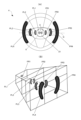
- FIG. 1 is a diagram showing a configuration example of a driving support system and a vehicle display device.
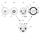
- FIG. 2(A) is a diagram showing an arrangement example in the vehicle of the projection device that constitutes the illumination unit
- FIG. 2(B) is a front view of the steering wheel
- FIG. 2(C) is a projection on the steering wheel.
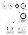
- FIGS. 3(A) to 3(E) are diagrams showing examples in which driving responsibility is transferred from the vehicle to the driver (first sensation)
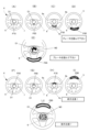
- FIG. 10 is a diagram showing an example of creating a feeling that driving responsibility is transferred from the driver to the vehicle (second feeling).
- FIGS. 1 is a diagram showing a configuration example of a driving support system and a vehicle display device.
- FIG. 2(A) is a diagram showing an arrangement example in the vehicle of the projection device that constitutes the illumination unit
- FIG. 4A and 4B show an example in which the first to third display elements are expressed using perspective so that the driver perceives an image with a sense of depth (three-dimensional effect).
- FIG. 4 is a diagram showing;
- FIG. 5 is a diagram showing another example of expressing each of the first to third display elements using the perspective method so that the driver perceives an image with a sense of depth (three-dimensional effect).
- FIG. 6A is a diagram showing a display example of a pair of separated linear or band-shaped patterns (first, second, and third display elements) displayed on the steering wheel; ) shows an example of expressing the first to third display elements shown in FIG.
- FIG. 4 is a diagram showing;
- FIG. 7 expresses each of the first to third display elements shown in FIG.
- FIGS. 8A to 8G are display examples when driving responsibility shifts from the vehicle to the driver (including display indicating change in driving support level by annular pattern, highlight display, and display of gripping position). , and an example of voice guidance.
- FIG. 9 is a diagram showing an example of displaying an icon indicating a driving state (driving mode) at the center of the steering wheel.
- FIGS. 10A to 10I show display examples when driving responsibility shifts from the vehicle to the driver (display, highlighting, and grasping indicating a change in the driving support level by a separated linear or strip pattern).
- FIGS. 11A to 11E are diagrams showing an example of changing the display position and display movement direction on the steering wheel in correspondence with the action that the driver should take next
- FIGS. (J) is a diagram showing another example
- FIGS. 12(A) to 12(F) are diagrams showing an example in which the display showing the change in the driving support level and the display showing the action that the driver should take next are performed simultaneously.
- FIGS. 13A to 13E are diagrams showing display examples (modifications) in which display using an annular pattern and a pair of separated linear or band-like patterns are used together.
- FIG. 14A to 14E show that when the annular pattern is moved from the inside to the outside of the steering wheel, the width of the band-shaped pattern at the connecting portion is larger than the width of the annular pattern at the central portion and the outer edge.
- FIG. 10 is a diagram showing an example (application example) in which the value of is set to be large (wide).
- FIGS. 15A to 15H are diagrams showing display examples (including advance notification processing) when driving assistance is expanded.
- FIG. 16 is a diagram showing another example of displaying an icon indicating the driving state (driving mode) in the central portion of the steering wheel.
- FIG. 17A is a diagram showing a display example (including a mark (light mark) displayed at the center of the steering wheel) in the automatic driving state, and FIGS.
- FIG. 17B and 17C are the center of the steering wheel.
- FIG. 10 is a diagram showing another example of a mark (optical mark) displayed on the part;
- FIG. 18 is a flowchart illustrating an example of a display control procedure.
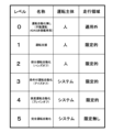
- FIG. 19 is a diagram for explaining the driving support level (automatic driving level).
- FIG. 20 is a diagram showing an example of a caution period when the driving support level (automatic driving level) is changed.
- FIG. 19 is a diagram for explaining the driving support level (automatic driving level).
- the driving support level (automatic driving level) can be divided into levels “0" to "5" as shown.
- the driving subject is a person (driver). In other words, the driver has greater driving responsibility.
- the main driver is the vehicle (vehicle system). In other words, the vehicle has more driving responsibility.
- an increase in the driving assistance level (automatic driving level) may be referred to as “expansion of the driving assistance level”, and a decrease may be referred to as “reduction in the driving assistance level”.
- FIG. 20 is a diagram showing an example of a caution period when the driving support level (automatic driving level) is changed.
- the automatic driving level is changed during the automatic driving level change period TM1 (time t1 to t2).
- the period from time t2 to t3 immediately after that is the period TM2 immediately after the automatic driving level change.
- the period from time t3 to t4 is the operation period TM3 based on the post-change level.
- FIG. 1 is a diagram showing a configuration example of a driving support system and a vehicle display device.
- the width direction of the vehicle (horizontal direction as seen from the driver) is the X direction
- the height direction of the vehicle is the Y direction
- the forward direction as seen from the driver is the Z direction.
- a driving support system (automatic driving system) 10 has an information collection unit 12 that collects various types of information from an ECU or the like, an AI module 14, a speed control module 16, and a steering control module 18.
- the display device (vehicle display device) 100 can be mounted on the vehicle (self-vehicle) 1 as an in-vehicle projector, for example.
- the display device (vehicle display device) 100 can be called a display system, a vehicle display system, an information presentation system, or a vehicle information presentation system. Hereinafter, it is written as "vehicle display device”.
- the vehicle display device 100 includes a display control device 102 having a function of controlling display in the vehicle, a voice guidance unit 105, a motion detection unit 108 for detecting motions of the driver and passengers by image processing and the like, A display control unit 110 that controls display by display devices 122 and 123 such as a liquid crystal display device provided on an instrument panel 120, a projector (projection device) 112 that can be a component of an illumination unit, and a driver and a passenger. and a motion detection camera 114 for detecting the motion of the camera.
- the display control device 102 is composed of, for example, one or more processors.
- the control unit 104 as a functional block is configured by the processor operating according to the computer program stored in the memory.
- an effective display control method can be realized simply and easily as long as there is a computer system with a basic configuration such as a processor and memory.
- the control unit 104 is supplied with, for example, various information related to the driving assistance level from the AI module 14 of the driving assistance system (automatic driving system) 10 .
- the controller 104 of the display control device 102 is notified in advance of the change in the driving assistance level. This notification is supplied to the control unit 104 as change prediction information, for example.
- control unit 104 When the change prediction information is supplied, the control unit 104 performs display control processing (first display control processing) for informing the driver of the change in the driving support level.
- the control unit 104 controls the operation of a projector (projection device) 112, which is a component of the lighting unit, to project an image onto the steering wheel (steering wheel) 4 of the vehicle 1, thereby displaying a display element having a two-dimensional spread. Displayable. In the lower part of FIG. 1, patterns P1 to P4 of concentric circles or rings are displayed.
- the pattern P3 displayed on the connecting portions of the steering wheel 4 (spokes: reference numerals 9a, 9b, and 9c in FIG. 2(B)) is only partially displayed as a circular or annular pattern.
- the pattern P3 is an arcuate "line pattern” when a circular pattern is projected, and an arcuate “strip pattern” when an annular pattern is projected.
- the “illumination unit” is configured by the projector (projection device) 112 alone, or by the projector 112 and a light emitting unit (having at least one light emitting element 116) provided on the steering wheel 4 of the vehicle 1. It can be assumed that it is configured, or that it is configured solely by the light-emitting portion (having a plurality of (multiple) light-emitting elements 116) provided on the steering wheel 4.
- FIG. 1 is configured by the projector (projection device) 112 alone, or by the projector 112 and a light emitting unit (having at least one light emitting element 116) provided on the steering wheel 4 of the vehicle 1. It can be assumed that it is configured, or that it is configured solely by the light-emitting portion (having a plurality of (multiple) light-emitting elements 116) provided on the steering wheel 4.
- the projector 112 is used at night, and in an environment where the intensity of outside light is strong during the day, the projector 112 and a light emitting unit including at least one light emitting element 116 are used together, or a plurality of light emitting elements are used. Applied use cases can also be envisioned, such as using only the light-emitting portion consisting of 116 .
- the projector 112 has a light source and an optical system for projection (not shown). Further, the control unit 104 can control the operation of the voice guide unit 105 to output voice (guide voice) through the speaker 107 .
- the control unit 104 can prompt the driver to grip the steering wheel by outputting, for example, a guidance voice saying, "Please hold the steering wheel.” For example, it can be displayed by a linear or band-shaped display piece (light strip) (see FIG. 9, which will be described later).
- the motion detection unit 108 analyzes the image captured by the motion detection camera 114 to detect the gripping motion, and the control unit 104 detects the gripping motion based on the detection information. to stop the output of the guide voice and the display of the display strip.
- a concave portion 6 having a circular outer shape (a circle indicating the outer shape is indicated by a broken line in FIG. 1) is provided.
- This circular concave portion 6 can be used as a central display area (symbol D1 in FIG. 2(B)) for displaying an optical mark composed of characters, figures, symbols, and the like.
- the motion detection unit 108 detects the steps (edges) of the circular concave portion 6 by image analysis, so that, for example, it is easy to accurately identify the center position of the concentric circles. can get.
- Each of the annular patterns P1 to P4 formed on the steering wheel 4 is preferably drawn by a perspective method (including linear perspective method and aerial perspective method), so that the driver can have a sense of depth.
- a perspective method including linear perspective method and aerial perspective method
- One stereoscopic image can be perceived (see FIGS. 4A, 4B, and 5; details will be described later).
- dynamic display control such as displaying the patterns P1 to P4 at different times, the driver is instructed to move from the front of the vehicle 1 toward the steering wheel 4, or from the steering wheel 4. It is also possible to give a sense of movement toward the front of the vehicle 1 (this point will also be described later).
- FIG. 2(A) is a diagram showing an arrangement example in the vehicle of the projection device that constitutes the illumination unit
- FIG. 2(B) is a front view of the steering wheel
- FIG. 2(C) is a projection on the steering wheel.
- annular pattern first and third display elements
- second display element second display element
- FIG. 2 the same reference numerals are given to the parts that are common to those in FIG. This point also applies to subsequent figures. Also, FIG. 2C is the same as the diagram shown on the lower side of FIG.
- the projector 112 is installed near the ceiling of the vehicle 1 .
- the driver 3 sits on the seat 132 and looks at the front.
- the projector 112 can project an image onto the surface of the steering wheel 4 facing the driver 3 to form a light display.
- the steering wheel 4 includes a central portion (hub or boss) 7, an outer edge portion (rim) 5, a connecting portion 9a connecting the central portion 7 and the outer edge portion 5, 9b and 9c, and has a two-dimensional structure when viewed from the driver 3.
- FIG. 2B By using each of the above portions as a display area for display elements (patterns, marks, etc.), it is possible to display an image with a two-dimensional spread.
- the external shape of the steering wheel 4 is generally a symmetrical shape that is well-proportioned to the left and right.
- the driver perceives an image with a sense of depth (three-dimensional effect) by the production of each of the above patterns (for example, a devised expression method that produces a predetermined effect), and the image , it is also possible to give a motion by the above-mentioned production effect. In other words, it is possible to make the driver 3 feel the movement toward a predetermined direction through dynamic display effects.
- FIGS. 3(A) to 3(E) are diagrams showing examples of generating a sense (first sense) that driving responsibility shifts from the vehicle to the driver
- FIGS. 3(F) to 3(J) FIG. 10 is a diagram showing an example of creating a feeling that driving responsibility is transferred from the driver to the vehicle (second feeling).
- control unit 104 of the display control device 102 provides an illumination unit (here, , the projector 112) to control the effect of display by light.
- a first display element formed in the central portion 7 of the steering wheel 4 (patterns P1 and P2 in FIGS. 3A and 3B), and a second display element formed in the connecting portions 9a to 9c (FIG. 3 (C) pattern P3) and the effect by the third display element (pattern P5 in FIG. 3(D)) formed on the outer edge portion 5 are controlled.
- the driver 3 can be made to feel a three-dimensional image with a sense of depth. 3(A) to 3(D), the patterns are displayed at different times so that the driver 3 can see the vehicle as indicated by the arrow A1 in FIG. 3(E). The movement from the front part (tip part) of 1 toward the steering wheel 4 can be felt.
- FIGS. 3A to 3D show examples in which the patterns P1 to P4 are displayed at different times, but are not limited to this.
- the patterns P1 to P4 are displayed at the same time.
- the brightness and brightness of the pattern P1 are instantaneously increased.
- a similar motion sensation can be given to the driver by causing it.
- the driving of the vehicle 1 can be improved by, for example, performing display effects using lights as shown in FIGS.
- the driver is responsible for the first sense of moving from the front portion of the vehicle 1 forward of the steering wheel 4 toward the steering wheel 4 (the sense of movement indicated by arrow A1 in FIG. 2(E)). 3 can be generated.
- the steering wheel 4 can be regarded as a structure that spatially separates (partitions) the front portion (tip portion) of the vehicle 1 and the driver 3 .
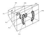
- one virtual plane (indicated by a dashed line in the figure) having a two-dimensional spread in real space is assumed to be in contact with the surface of the steering wheel 4.
- a virtual first responsibility area (vehicle responsibility area) AR1 is set on the front side of the vehicle 1
- a virtual second responsibility area (driving area) is set on the driver 3 side.
- Responsibility area) AR2 is set.
- the concept of the responsibility area is instantly recalled by the learning, and the person moves from the first responsibility area AR1 to the second responsibility area AR2. can be instantly recognized (understood). Therefore, the driver 3 can quickly, clearly and reliably understand that the driving assistance level has been reduced.
- the display patterns P4 to P1 are displayed in the order shown in FIGS. 3(F) to (I).
- the driver 3 can feel the movement (second sensation) of moving from the steering wheel 4 to the front of the vehicle 1, as indicated by the arrow A2 in FIG. 3(J). .
- the driver 3 can instantly recognize the transition from the second responsibility area AR2 to the first responsibility area AR1.
- the driver when the driving support level (which can be rephrased as an automatic driving level, a driving mode, etc.) is changed, the driver is given a first sense of moving from the back side to the front side as seen from the driver, and The driver can intuitively recognize the content of the change without a sense of incompatibility by performing display control (effect by a display element) that causes at least one of the second feeling of moving from the rear to the rear.
- display control effect by a display element
- the driver 3 does not follow the movement of the display element with his eyes and confirm the direction of movement to understand the change, as in the conventional art. be. Therefore, it is possible to shorten the time required for the driver to understand that the driving mode has been changed. This also contributes to safe driving and the like.
- connecting portions 9a to 9c, and outer edge portion 5 of the steering wheel 4 may not be used as areas forming display elements.
- the display elements are not formed in the connecting portions 9a to 9c. Therefore, such examples are also included in the technical scope of the present invention.
- FIGS. 4A and 4B show an example in which the first to third display elements are expressed using perspective so that the driver perceives an image with a sense of depth (three-dimensional effect).
- FIG. 4 is a diagram showing;
- Linear perspective is an expression method that expresses perspective, in which objects in the foreground appear smaller as they go further away, using line drawings.
- air perspective was originally defined as "the light that enters the eye is actually affected by the air (atmosphere), so the farther the object is from the point of view, the more air there is between the point of view and the object. It is a perspective expression method that utilizes the fact that it is sandwiched, and as a result, it becomes more bluish or the outline becomes more unclear and appears hazy.” It is a method of expressing a sense of perspective by drawing, and it can also be said to be a method of perspective using colors and tone of color (tone, outline, shadow, etc.).
- the driver can see the third display element. It can be envisioned that the display element is located near itself, the second display element is located further away, and the first display is located further away. As a result, an image with a three-dimensional effect (perceived depth) can be displayed to the driver.
- annular patterns P1 to P4 are not colored.
- FIG. 4A since the size of the annular patterns P1 to P4 increases in order, it can be said that the annular patterns P1 to P4 are represented by the method of linear perspective. Therefore, it is possible to make the driver perceive a three-dimensional image (stereoscopic image) with a sense of depth.
- the annular patterns P1 to P4 are colored blue, for example. However, the shade is different. As the density increases in the order of the patterns P1 to P4, the pattern P1 appears hazy to the driver 3, and the patterns P2 to P4 appear to improve in definition in the order. Therefore, the driver 3 can be made to perceive a clearer three-dimensional image.
- FIG. 5 is a diagram showing another example of expressing each of the first to third display elements using the perspective method so that the driver perceives an image with a sense of depth (three-dimensional effect).
- the annular patterns P1 to P4 are colored and have different colors.
- the pattern P1 is light blue
- the pattern P2 is blue
- the pattern P3 is yellow
- the pattern P4 is red.
- FIG. 6A is a diagram showing a display example of a pair of separated linear or band-shaped patterns (first, second, and third display elements) displayed on the steering wheel; ) shows an example of expressing the first to third display elements shown in FIG.
- FIG. 4 is a diagram showing;
- the display element is composed of a pair of separated linear or band-shaped display strips (light strips).
- a pair of arc-shaped display pieces PL1 and PR1, and PL2 and PR2, which are separated left and right and displayed, are the first display elements formed in the central portion 7 of the steering wheel 4.
- a pair of display pieces PL3 and PR3 are second display elements formed on the left and right connecting portions 9a and 9b of the steering wheel 4.
- a pair of display pieces PL4 and PR4 is a third display element formed on the outer edge portion 5 of the steering wheel 4. As shown in FIG.
- each display piece (PL1 to PL4, PR1 to PL4) is a virtual concentric circle (for example, 3 (A) to (D) (see patterns P1 to P4 in 3 (A) to (D)) and is arranged on a virtual straight line (mark Q in FIG. 6 (A)) that passes through the point U and intersects each concentric circle is preferred.
- the display piece can prompt the driver to step on the brake or to check the front.
- the driver can easily know that automatic driving is being carried out smoothly by changing the position of the display piece corresponding to the automatic rotation of the steering wheel. can give you peace of mind.
- a straight line in other words, By displaying (arranging) each of the pair of display pieces on the straight line forming the diameter of the maximum circle, for example, while maintaining left-right balance, etc. image can be displayed.
- a specific display example will be described later.
- FIG. 6(B) is a diagram corresponding to FIG. 4(B) shown above.
- a combination of linear perspective and aerial perspective is used to create an image with a sense of depth.
- Each display element is colored blue, for example. However, the shading is different, and the closer the display elements are to the front, the higher the definition.
- FIG. 7 expresses each of the first to third display elements shown in FIG. 6(A) using perspective in order to make the driver perceive an image with a sense of depth (three-dimensional effect). It is a figure which shows the example of.
- FIG. 7 is a diagram corresponding to FIG. 5 shown above.
- a combination of linear perspective and aerial perspective is used to create an image with a sense of depth.
- Each display element (display pattern) is colored and has a different color. Cool colors (shrinking colors) such as light blue and blue are used for patterns that are felt far from the driver 3, and warm colors (expanding colors) such as yellow and red are used for patterns that are felt close. , the sense of depth can be produced more vividly.
- FIGS. 8A to 8G are display examples when driving responsibility shifts from the vehicle to the driver (including display indicating change in driving support level by annular pattern, highlight display, and display of gripping position). , and an example of voice guidance.
- the display element when the driver 3 is made to feel a movement from the back side to the front side (first sensation), the display element is displayed at the outer edge portion 5 of the steering wheel 4, or at the timing. After the timing, an enhancement process is performed on the display element.
- FIGS. 8(A) to (D) are the same as FIGS. 3(A) to (D) shown above. After performing the display of FIG. 8(C) or FIG. 8(D), the display shifts to the display of FIG. 8(E).
- FIG. 8(E) the pattern P4 displayed on the outer edge 5 of the steering wheel 4 is emphasized.
- the pattern after the enhancement process is denoted by P4'.
- Endancement processing can be realized, for example, by temporarily increasing the luminance and brightness of the annular pattern or display piece, or by temporarily blinking the pattern or display piece.
- the "enhancement process” can be said to be “a process of temporarily changing the display state to improve the attractiveness”.
- the driver's vision to the display by directing the driver's vision to the display, it is possible to impress the driver that the driving support level has been changed and prevent the driver from overlooking it, or to make sure that the driver recognizes the change in the driving support level. be able to. Also, when the driving responsibility shifts from the vehicle 1 to the driver 3, the driver 2 is clearly informed of the driving responsibility and prepared to grip the steering wheel 4 (prepared in advance). Such a preparation effect can also be obtained.
- FIG. 8(E) a guide voice saying "Automatic driving section has ended” is output from the speaker 107 (see FIG. 1).
- FIG. 8F linear or strip-shaped display pieces PL4 and PR4 are displayed on the left and right sides of the outer edge 5 of the steering wheel 4 to show the driver 3 where to hold the steering wheel 4. . Also, a guide voice saying "please hold the steering wheel” is output from the speaker 107.
- FIG. 8F linear or strip-shaped display pieces PL4 and PR4 are displayed on the left and right sides of the outer edge 5 of the steering wheel 4 to show the driver 3 where to hold the steering wheel 4. .
- a guide voice saying "please hold the steering wheel” is output from the speaker 107.
- FIG. 8(G) After the display of FIG. 8(F), shift to FIG. 8(G).
- FIG. 8(G) a guide voice saying “Transition to manual operation” is output from the speaker 107.
- FIG. 8(G) a guide voice saying "Transition to manual operation" is output from the speaker 107.
- FIG. 9 is a diagram showing an example of displaying an icon indicating a driving state (driving mode) at the center of the steering wheel.
- FIG. 9 is a diagram corresponding to FIG. 8(F) shown above.
- an icon M1 is also displayed in the central display area D1 of the central portion 7 of the steering wheel 4 to prompt the user to grip the steering wheel.
- a light mark including at least one of characters, graphics, and symbols is displayed to indicate information about the driving state, the driving situation, or the next action to be taken by the driver.
- useful information can be displayed in an easy-to-see or easy-to-understand manner for the driver.
- FIGS. 10A to 10I show display examples when driving responsibility shifts from the vehicle to the driver (display, highlighting, and grasping indicating a change in the driving support level by a separated linear or strip pattern). (including display of position) and an example of voice guidance.
- FIG. 10 is a diagram corresponding to FIG. 8 shown above.
- emphasis processing is performed on linear or band-shaped display elements (patterns) (FIGS. 8(E) to (G)).
- FIGS. 10(A) to (D) are the same as FIGS. 8(A) to (D).
- FIGS. 10(H) and (I) are the same as FIGS. 8(F) and (G).
- FIG. 10 instead of FIG. 8(E), one of FIGS. 10(E) to 10(H) is highlighted.
- the emphasis processing may be performed after the display of FIG. 10(D), or after FIG. 10(C), omitting FIG. You may shift to the display of any of
- the brightness and brightness of a pair of separated linear or band-shaped (arc-shaped here) display strips (light strips) PL4′ and PR4′ are temporarily improved or temporarily
- the color, tone, or saturation is changed to enhance the attractiveness.
- FIG. 10(F) the display pieces PL5 and PR5 are temporarily extended. Comparing FIGS. 10(E) and (F), in FIG. 10(F), the display piece extends upward by L1 and downward by L2.
- FIG. 10(G) a pair of display pieces PL6 and PR6 are swung along the outer edge portion 5 of the steering wheel 4.
- FIG. 10(G) a pair of display pieces PL6 and PR6 are swung along the outer edge portion 5 of the steering wheel 4.
- the driver 3 can be prepared in advance for the action to be taken next. This contributes to safe and secure driving.
- FIGS. 11A to 11E are diagrams showing an example of changing the display position and display movement direction on the steering wheel in correspondence with the action that the driver should take next
- FIGS. (J) is a diagram showing another example.
- FIG. 11 shows a display example when other useful information (information other than the driving level change information) is displayed in relation to the notification of the driving level change.
- FIGS. 11A to 11D display pieces P10 to P40 of different sizes are attached to the center portion 7 of the steering wheel 4, the connection portion 9c extending downward from the center portion 7, and the outer edge portion 5 at different times. are displayed.
- the driver 3 moves the linear or strip-shaped display pieces P10 to P40 in a direction (here, downward) according to the next action (here, stepping on the brake).
- FIG. 11(D) a guide voice saying "Please step on the brake” is output from the speaker 107.
- the driver 3 can be made to recognize in advance what to do and be prepared. can.
- FIG. 11(E) a linear or strip-shaped display piece P40 is displayed below the outer edge of the steering wheel 4, and further, in the central display area D1 in the central portion 7 of the steering wheel 4, the brake is displayed. An icon M2 prompting stepping is displayed. This allows the driver 3 to reliably and quickly understand that the operation of stepping on the brake is necessary. Also in FIG. 11(E), the speaker 107 outputs a guide voice saying "please step on the brake".
- FIGS. 11(F) to (I) display pieces P50 to P80 of different sizes are displayed on the central portion 7 and the outer edge portion 5 of the steering wheel 4 at different times.
- the driver 3 moves the linear or strip-shaped display pieces P50 to P80 in a direction (upward in this case) according to the action to be taken next (here, an action of paying attention to the front).
- a guide voice of “Caution ahead” is output from the speaker 107 .
- an icon M3 is further displayed in the central display area D1 in the central portion 7 of the steering wheel 4 to prompt the driver to pay attention to the front.
- FIGS. 12(A) to 12(F) are diagrams showing an example in which the display showing the change in the driving support level and the display showing the action that the driver should take next are performed simultaneously.
- the example in FIG. 12 is also basically the same as the example in FIG. However, in FIG. 12, the display control shown in FIG. 6A (display control for moving a pair of display pieces left and right) and the display control shown in FIGS. ) are simultaneously performed. In this respect, it differs from FIG.
- the speaker 107 outputs a guide voice saying "Hold the steering wheel and step on the brake.”
- the speaker 107 outputs a guidance voice saying "Please hold the steering wheel and step on the brake".
- the display piece P40 that prompts him to step on the brake continues to be displayed, as shown in FIG. 12(F). Also, a guide voice saying "Please step on the brake" is repeatedly output from the speaker 107 .
- FIGS. 13A to 13E are diagrams showing display examples (modifications) in which display using an annular pattern and a pair of separated linear or band-like patterns are used together.
- annular patterns P1, P2, P3, and P4 are displayed at different times.
- FIG. 13(C) a pair of linear or strip-shaped display pieces (patterns) PL3 and PR3 are displayed on the central portion (hub) 7 of the steering wheel 4.
- FIG. 13D the pair of linear or strip-shaped display pieces (patterns) PL4 and PR4 are displayed on the left and right connecting portions (spokes) 9a and 9b of the steering wheel 4.
- spokes spokes
- FIG. 13(E) a pair of linear or strip-shaped display pieces (patterns) PL5 and PR5 are displayed at the left and right positions of the outer edge (rim) 5 of the steering wheel 4.
- the speaker 107 outputs a guidance voice saying, "The automatic driving section has ended. Please hold the steering wheel.”
- FIGS. 14A to 14E show that when the annular pattern is moved from the inside to the outside of the steering wheel, the width of the band-shaped pattern at the connecting portion is larger than the width of the annular pattern at the central portion and the outer edge.
- FIG. 10 is a diagram showing an example (application example) in which the value of is set to be large (wide).
- first circle or ring patterns P1 and P2 are sequentially displayed on the central portion 7 of the steering wheel, and in FIG. In 9c, a part (linear or strip-shaped display piece) P3 of the pattern of the second circle or ring concentric with the first circle or ring is displayed, and in FIG. , a pattern P4 of a third circle or torus that is concentric with the first and second circles or tori rings is displayed.
- FIG. 14(C) it is undeniable that the inability to display the entire circle or ring on the connecting portions 9a and 9b of the steering wheel 4 is likely to cause discomfort. Therefore, as shown in FIG. 14(E), display control is performed to suppress the discomfort.
- the line width or band width D2 of the second circle or ring is set larger than the line width or band width D1 of the first and third circles or rings.
- the display element when the display element is moved from the inside to the outside (or may be moved from the outside to the inside), the display element , 9b, the period during which a sense of discomfort occurs becomes longer.
- the band width of the light band is made larger than the band width of the rings of the central portion 7 and the outer edge portion 5. are also made large (wide) so that the connecting portions 9a and 9b can be moved quickly so that they can pass through in a short period of time. Thereby, discomfort can be reduced.
- FIGS. 15A to 15H are diagrams showing display examples (including advance notification processing) when driving assistance is expanded.
- FIGS. 15(A) to (D) are the same as FIGS. 3(F) to (I) shown above.
- the driver 3 is given a sense of motion (movement) from the near side to the far side (second sense). Is possible.
- FIGS. 15(E) and (F) before the second sensation is caused to the driver (before the display of FIG. 15(A)) in order to notify the driver 3 of the expansion of the driving assistance.
- the outer edge portion 5 of the steering wheel 4 is subjected to a display process that enhances the attractiveness.
- HL and HR indicate the left and right hands of the driver 3 who are holding the steering wheel.
- FIG. 15(E) shows an intermittent light band PQ4.
- the emphasis processing shown in FIG. 8(E) is performed first.
- FIG. 15(E), FIG. 15(F), or FIG. 15(A) a guide voice saying "Transition to automatic driving” is output from the speaker 107. After FIG. 15(E) or (F), it shifts to FIG. 15(A) or FIG. 15(B).
- FIG. 15G strip-shaped (arc-shaped) display pieces P90 to P93 are displayed on the central portion 7 of the steering wheel 4.
- FIG. 15G strip-shaped (arc-shaped) display pieces P90 to P93 are displayed on the central portion 7 of the steering wheel 4.
- strip-shaped (arc-shaped) display pieces P94 to P97 are displayed in the central display area D1 in the central portion 7 of the steering wheel 4.
- FIG. 15(H) strip-shaped (arc-shaped) display pieces P94 to P97 are displayed in the central display area D1 in the central portion 7 of the steering wheel 4.
- a guide voice saying "automatic operation has started” is output from the speaker 107.
- FIG. 16 is a diagram showing another example of displaying an icon indicating the driving state (driving mode) in the central portion of the steering wheel.
- FIG. 16 is a diagram corresponding to FIG. 9 shown above.
- an icon M4 is displayed in the central display area D1 in the central portion 7 of the steering wheel 4 to prompt the driver 3 to release the gripped steering wheel.
- the speaker 107 outputs a guidance voice saying, "Automatic driving has started. Please take your hands off the steering wheel.”
- FIG. 17A is a diagram showing a display example (including a mark (light mark) displayed at the center of the steering wheel) in the automatic driving state, and FIGS. 17B and 17C are the center of the steering wheel.
- FIG. 10 is a diagram showing another example of a mark (optical mark) displayed on the part;
- Fig. 17 shows a display example during automatic operation.
- control is performed to move strip-shaped display elements (arc-shaped display pieces) P100 and P102 in correspondence with automatic rotation of the steering wheel 4 by automatic driving control.
- the driver can visually confirm that the automatic driving is being carried out smoothly, and can obtain a sense of security.
- FIG. 17(A) in the central display area D1 of the steering wheel 4, a plurality of circles are combined to display a figure (or pattern) with a decorative effect.
- the figure (or pattern) may be given movement.
- the driver's sense of security during automatic driving can be increased, and a comfortable driving environment can be provided.
- a mark M6 indicating the manufacturer of the vehicle display device, etc. is displayed, and as shown in FIG. It is also possible to display characters indicating Further, in FIG. 17(C), the speaker 107 outputs a guidance voice saying "An ambulance is approaching.” Through such display control, it is possible to inform the driver of various types of information without causing discomfort during automatic driving.
- FIG. 18 is a flowchart illustrating an example of a display control procedure.
- step S1 change information of the autonomous driving level (prediction information of change of the driving level) is acquired from the AI module of the autonomous driving system.
- step S2 it is determined whether there is a change in the automatic driving level. If Y, the process proceeds to step S3, and it is determined whether the driving support level is reduced (whether the driving level is lowered). If Y in step S3, the process proceeds to step S4, and if N, the process proceeds to step S7.
- step S4 display control is performed to cause the driver to feel the sensation of moving from the back side to the front side (first sensation).
- step S5 an emphasizing process for emphasizing changes in the driving support level is performed.
- step S6 a display showing what the driver should do next is displayed.
- step S7 display control is performed to cause the driver to feel the sensation of moving from the near side to the far side (second sensation). Subsequently, in step S8, display processing after transition to automatic operation is performed.
- step S9 it is determined whether or not to end the display. If it is Y, the display is terminated, and if it is N, the process returns to step S1.
- the above display control method can be implemented simply and easily with a computer system having a basic configuration such as a processor and a memory. can.
- an area on the steering wheel that the driver should grip is indicated by a light mark, but if the driver does not grip the steering wheel, the light mark can be flashed or changed to a warning color and flashed. is also possible. Such changes can be made as appropriate.
- display elements, display pieces, etc. can also be rephrased as “display by light (light display)” or “light mark (light mark)”.
- display control display effect in which display elements are displayed on the steering wheel using a projector or a light-emitting element can also be referred to as "light marking.”
- vehicle can be broadly interpreted as a vehicle.
- terms related to driving assistance are also interpreted in a broad sense, taking into consideration, for example, the viewpoint of information in a broad sense that is useful for driving a vehicle.
- display devices and display devices for vehicles include those used as simulators (for example, aircraft simulators, simulators as game devices, etc.).
- Speed control module 18 Steering control module 100 Display device (vehicle display device, in-vehicle display device, or in-vehicle projector) 102 Display control device (processor) 104 Control Section 105 Audio guide section 107 Speaker 108 Action detection section 110 Display control section 112 Projector (projection section, projection light source section) for action detection Camera (occupant imaging camera) 116 Light-emitting element (or illumination element) such as LED 120 Instrument panel 122, 123 Display device (display unit) such as liquid crystal display device P1 ⁇ P4 ... Display elements formed on the steering wheel (pattern, light display, light pattern, or light mark), PL1 to PL4, ⁇ PR1 to PR4 ...
- Display pieces strip lights, arc-shaped lines, etc. or band-shaped light pattern or light mark
- D1 Central display area in the center of the steering wheel
- M1 to M7 Marks such as letters, figures, symbols displayed in the central display area (icons, including patterns, etc.).
Landscapes
- Engineering & Computer Science (AREA)
- Chemical & Material Sciences (AREA)
- Combustion & Propulsion (AREA)
- Transportation (AREA)
- Mechanical Engineering (AREA)
- Physics & Mathematics (AREA)
- Computer Hardware Design (AREA)
- General Physics & Mathematics (AREA)
- Theoretical Computer Science (AREA)
- Steering Controls (AREA)
Priority Applications (4)
| Application Number | Priority Date | Filing Date | Title |
|---|---|---|---|
| DE112022005688.6T DE112022005688T5 (de) | 2021-11-29 | 2022-11-28 | Anzeigesteuervorrichtung, Anzeigevorrichtung und Anzeigesteuerverfahren |
| CN202280078357.4A CN118339049A (zh) | 2021-11-29 | 2022-11-28 | 显示控制装置、显示装置及显示控制方法 |
| JP2023563769A JPWO2023095899A1 (https=) | 2021-11-29 | 2022-11-28 | |
| US18/713,787 US12397644B2 (en) | 2021-11-29 | 2022-11-28 | Display control device, display device, and display control method |
Applications Claiming Priority (2)
| Application Number | Priority Date | Filing Date | Title |
|---|---|---|---|
| JP2021-193452 | 2021-11-29 | ||
| JP2021193452 | 2021-11-29 |
Publications (1)
| Publication Number | Publication Date |
|---|---|
| WO2023095899A1 true WO2023095899A1 (ja) | 2023-06-01 |
Family
ID=86539649
Family Applications (1)
| Application Number | Title | Priority Date | Filing Date |
|---|---|---|---|
| PCT/JP2022/043695 Ceased WO2023095899A1 (ja) | 2021-11-29 | 2022-11-28 | 表示制御装置、表示装置、及び表示制御方法 |
Country Status (5)
| Country | Link |
|---|---|
| US (1) | US12397644B2 (https=) |
| JP (1) | JPWO2023095899A1 (https=) |
| CN (1) | CN118339049A (https=) |
| DE (1) | DE112022005688T5 (https=) |
| WO (1) | WO2023095899A1 (https=) |
Families Citing this family (1)
| Publication number | Priority date | Publication date | Assignee | Title |
|---|---|---|---|---|
| KR20240084339A (ko) * | 2022-12-06 | 2024-06-13 | 현대모비스 주식회사 | 모빌리티의 메시지 전달 시스템 |
Citations (5)
| Publication number | Priority date | Publication date | Assignee | Title |
|---|---|---|---|---|
| WO2015145605A1 (ja) * | 2014-03-26 | 2015-10-01 | 日産自動車株式会社 | 車両用情報呈示装置 |
| JP2018203012A (ja) * | 2017-06-02 | 2018-12-27 | 本田技研工業株式会社 | 車両制御システム、車両制御方法、およびプログラム |
| JP2019010929A (ja) * | 2017-06-29 | 2019-01-24 | 株式会社デンソーテン | 運転支援装置および運転支援方法 |
| US20200089226A1 (en) * | 2017-05-23 | 2020-03-19 | Bayerische Motoren Werke Aktiengesellschaft | Driving System for an Automated Drive with Means for Marking Regions on the Steering Wheel, and Corresponding Method |
| JP2021046033A (ja) * | 2019-09-17 | 2021-03-25 | 本田技研工業株式会社 | 操作子 |
Family Cites Families (7)
| Publication number | Priority date | Publication date | Assignee | Title |
|---|---|---|---|---|
| JP5495355B2 (ja) * | 2006-12-15 | 2014-05-21 | 現代自動車株式会社 | 自動車用ステアリングホイール用ディスプレイシステム |
| DE102013012779A1 (de) | 2013-07-31 | 2015-02-05 | Valeo Schalter Und Sensoren Gmbh | Verfahren zum Betreiben einer Fahrerassistenzeinrichtung zum autonomen Führen eines Kraftfahrzeugs und Kraftfahrzeug |
| US9840279B2 (en) * | 2016-03-21 | 2017-12-12 | Ford Global Technologies, Llc | Removable steering-wheel assembly for an autonomous vehicle |
| US20180281856A1 (en) * | 2017-03-31 | 2018-10-04 | Ford Global Technologies, Llc | Real time lane change display |
| KR102429959B1 (ko) * | 2017-12-11 | 2022-08-09 | 현대자동차주식회사 | 차량용 주행 제어시스템 및 방법 |
| JP2019142271A (ja) | 2018-02-16 | 2019-08-29 | 株式会社東海理化電機製作所 | ステアリング装置 |
| JP2022146537A (ja) * | 2021-03-22 | 2022-10-05 | 本田技研工業株式会社 | 操舵装置 |
-
2022
- 2022-11-28 JP JP2023563769A patent/JPWO2023095899A1/ja active Pending
- 2022-11-28 CN CN202280078357.4A patent/CN118339049A/zh active Pending
- 2022-11-28 WO PCT/JP2022/043695 patent/WO2023095899A1/ja not_active Ceased
- 2022-11-28 DE DE112022005688.6T patent/DE112022005688T5/de active Pending
- 2022-11-28 US US18/713,787 patent/US12397644B2/en active Active
Patent Citations (5)
| Publication number | Priority date | Publication date | Assignee | Title |
|---|---|---|---|---|
| WO2015145605A1 (ja) * | 2014-03-26 | 2015-10-01 | 日産自動車株式会社 | 車両用情報呈示装置 |
| US20200089226A1 (en) * | 2017-05-23 | 2020-03-19 | Bayerische Motoren Werke Aktiengesellschaft | Driving System for an Automated Drive with Means for Marking Regions on the Steering Wheel, and Corresponding Method |
| JP2018203012A (ja) * | 2017-06-02 | 2018-12-27 | 本田技研工業株式会社 | 車両制御システム、車両制御方法、およびプログラム |
| JP2019010929A (ja) * | 2017-06-29 | 2019-01-24 | 株式会社デンソーテン | 運転支援装置および運転支援方法 |
| JP2021046033A (ja) * | 2019-09-17 | 2021-03-25 | 本田技研工業株式会社 | 操作子 |
Also Published As
| Publication number | Publication date |
|---|---|
| DE112022005688T5 (de) | 2024-12-24 |
| JPWO2023095899A1 (https=) | 2023-06-01 |
| US12397644B2 (en) | 2025-08-26 |
| US20250042254A1 (en) | 2025-02-06 |
| CN118339049A (zh) | 2024-07-12 |
Similar Documents
| Publication | Publication Date | Title |
|---|---|---|
| CN107428299A (zh) | 信息提示装置 | |
| JP2012064096A (ja) | 車両用画像表示装置 | |
| WO2014017055A1 (ja) | 車両用視界支援装置 | |
| JPWO2017072953A1 (ja) | 車両情報表示制御装置および自動運転情報の表示方法 | |
| JP2004535971A (ja) | ヘッドアップディスプレイシステム及び方法 | |
| CN103359118A (zh) | 车辆瞥视光设备和用于控制该车辆瞥视光设备的方法 | |
| WO2023095899A1 (ja) | 表示制御装置、表示装置、及び表示制御方法 | |
| JP2019034610A (ja) | 車載システム及びヘッドアップディスプレイ装置 | |
| JP2017174091A (ja) | 覚醒維持装置及び覚醒維持方法 | |
| WO2018051734A1 (ja) | 投写型表示装置及びその制御方法 | |
| WO2023210684A1 (ja) | 表示制御装置、表示システム、及び表示制御方法 | |
| KR101763775B1 (ko) | Avm시스템 정보와 avn시스템 정보의 표시 방법 | |
| JP2021133804A (ja) | 車載表示装置、車載表示装置を制御する方法、及びコンピュータプログラム | |
| JP3923747B2 (ja) | 二輪車用ヘルメットマウントディスプレイシステム及びその表示制御方法 | |
| KR101416401B1 (ko) | 차량의 후방 영상 디스플레이장치 및 방법 | |
| JP6613616B2 (ja) | 車両用表示装置 | |
| JP6653184B2 (ja) | 車両用表示装置 | |
| CN119898190A (zh) | 显示控制装置、显示装置及显示控制方法 | |
| CN119511540A (zh) | 显示方法、显示设备、存储介质及交通工具 | |
| US20240227559A9 (en) | Improved Visualization with an AR HUD | |
| KR20170065739A (ko) | 헤드업 디스플레이 제어 장치 및 방법 | |
| JP7518598B2 (ja) | 表示制御装置 | |
| JP2020111079A (ja) | 制御装置、制御システム、および、制御方法 | |
| WO2025088992A1 (ja) | 虚像表示装置及び虚像表示方法 | |
| JP7012271B2 (ja) | 運転支援装置 |
Legal Events
| Date | Code | Title | Description |
|---|---|---|---|
| 121 | Ep: the epo has been informed by wipo that ep was designated in this application |
Ref document number: 22898681 Country of ref document: EP Kind code of ref document: A1 |
|
| ENP | Entry into the national phase |
Ref document number: 2023563769 Country of ref document: JP Kind code of ref document: A |
|
| WWE | Wipo information: entry into national phase |
Ref document number: 202280078357.4 Country of ref document: CN |
|
| WWE | Wipo information: entry into national phase |
Ref document number: 18713787 Country of ref document: US |
|
| WWE | Wipo information: entry into national phase |
Ref document number: 112022005688 Country of ref document: DE |
|
| 122 | Ep: pct application non-entry in european phase |
Ref document number: 22898681 Country of ref document: EP Kind code of ref document: A1 |
|
| WWG | Wipo information: grant in national office |
Ref document number: 18713787 Country of ref document: US |